US6058106A - Network protocol method, access point device and peripheral devices for providing for an efficient centrally coordinated peer-to-peer wireless communications network - Google Patents
Network protocol method, access point device and peripheral devices for providing for an efficient centrally coordinated peer-to-peer wireless communications networkDownload PDFInfo
- Publication number
- US6058106A US6058106AUS08/953,948US95394897AUS6058106AUS 6058106 AUS6058106 AUS 6058106AUS 95394897 AUS95394897 AUS 95394897AUS 6058106 AUS6058106 AUS 6058106A
- Authority
- US
- United States
- Prior art keywords
- peripheral
- block
- wireless
- access point
- acknowledgment
- Prior art date
- Legal status (The legal status is an assumption and is not a legal conclusion. Google has not performed a legal analysis and makes no representation as to the accuracy of the status listed.)
- Expired - Lifetime
Links
- 230000002093peripheral effectEffects0.000titleabstractdescription342
- 238000000034methodMethods0.000titleabstractdescription72
- 238000004891communicationMethods0.000titleabstractdescription24
- 238000012546transferMethods0.000description94
- 230000008569processEffects0.000description35
- 102100036409Activated CDC42 kinase 1Human genes0.000description30
- 230000005540biological transmissionEffects0.000description23
- 230000004044responseEffects0.000description23
- 206010009944Colon cancerDiseases0.000description20
- 238000010586diagramMethods0.000description14
- 230000002688persistenceEffects0.000description9
- 101710140250Activated CDC42 kinase 1Proteins0.000description8
- 230000006870functionEffects0.000description8
- 230000000977initiatory effectEffects0.000description8
- 230000000737periodic effectEffects0.000description8
- 230000000875corresponding effectEffects0.000description5
- 230000032258transportEffects0.000description5
- 230000008901benefitEffects0.000description4
- 238000013461designMethods0.000description4
- 238000001514detection methodMethods0.000description4
- 230000007246mechanismEffects0.000description4
- 230000001360synchronised effectEffects0.000description4
- 238000013519translationMethods0.000description4
- 230000014616translationEffects0.000description4
- 230000015572biosynthetic processEffects0.000description3
- 230000008859changeEffects0.000description3
- 238000012937correctionMethods0.000description3
- 125000004122cyclic groupChemical group0.000description3
- 238000007726management methodMethods0.000description3
- 238000005259measurementMethods0.000description3
- 238000012545processingMethods0.000description3
- 238000001228spectrumMethods0.000description3
- 239000004606Fillers/ExtendersSubstances0.000description2
- 235000008694Humulus lupulusNutrition0.000description2
- 230000003139buffering effectEffects0.000description2
- 230000015556catabolic processEffects0.000description2
- 230000006835compressionEffects0.000description2
- 238000007906compressionMethods0.000description2
- 238000006731degradation reactionMethods0.000description2
- 230000002452interceptive effectEffects0.000description2
- 238000004519manufacturing processMethods0.000description2
- 230000000116mitigating effectEffects0.000description2
- 238000010295mobile communicationMethods0.000description2
- 238000012544monitoring processMethods0.000description2
- 238000007493shaping processMethods0.000description2
- 230000011664signalingEffects0.000description2
- 230000003595spectral effectEffects0.000description2
- 238000003786synthesis reactionMethods0.000description2
- 241000950638Symphysodon discusSpecies0.000description1
- 241000289674VombatidaeSpecies0.000description1
- 230000001594aberrant effectEffects0.000description1
- 238000013459approachMethods0.000description1
- 230000006399behaviorEffects0.000description1
- 230000001413cellular effectEffects0.000description1
- 230000000295complement effectEffects0.000description1
- 239000002131composite materialSubstances0.000description1
- 230000001276controlling effectEffects0.000description1
- 238000010411cookingMethods0.000description1
- 230000003247decreasing effectEffects0.000description1
- 238000009826distributionMethods0.000description1
- 238000002592echocardiographyMethods0.000description1
- 238000005538encapsulationMethods0.000description1
- 239000012634fragmentSubstances0.000description1
- 230000010354integrationEffects0.000description1
- HOQADATXFBOEGG-UHFFFAOYSA-NisofenphosChemical compoundCCOP(=S)(NC(C)C)OC1=CC=CC=C1C(=O)OC(C)CHOQADATXFBOEGG-UHFFFAOYSA-N0.000description1
- 230000007774longtermEffects0.000description1
- 238000013507mappingMethods0.000description1
- 238000005457optimizationMethods0.000description1
- 230000010363phase shiftEffects0.000description1
- 238000012913prioritisationMethods0.000description1
- 230000001105regulatory effectEffects0.000description1
- 238000012552reviewMethods0.000description1
- 230000035945sensitivityEffects0.000description1
- 229910052710siliconInorganic materials0.000description1
- 239000010703siliconSubstances0.000description1
- 230000005236sound signalEffects0.000description1
- 241000894007speciesSpecies0.000description1
- 230000000153supplemental effectEffects0.000description1
- 230000002459sustained effectEffects0.000description1
- 238000012360testing methodMethods0.000description1
- 230000007704transitionEffects0.000description1
Images


Classifications
- H—ELECTRICITY
- H04—ELECTRIC COMMUNICATION TECHNIQUE
- H04W—WIRELESS COMMUNICATION NETWORKS
- H04W52/00—Power management, e.g. Transmission Power Control [TPC] or power classes
- H04W52/04—Transmission power control [TPC]
- H04W52/38—TPC being performed in particular situations
- H04W52/383—TPC being performed in particular situations power control in peer-to-peer links
Definitions
- DECTDigital European Cordless Telephone
- PHSPersonal Handyphone System
- micro-cellular systemshave been suggested for in-home application and, at first glance, seem suitable with respect to the systems' integral cordless telephone function.
- the current frequency plans for DECT and PHSare only available regionally.
- rules governing the 24 GHz ISMthe only band with worldwide availability, is not conducive to PHS or DECT protocols.
- PHS and DECTcannot withstand the bursted interference.
- these micro-cellular systemscontain significant additional complexity to handle community or campus deployment providing for intercell hand-off and roaming capability.
- the systemsare designed to tolerate multipath distortion present even in the systems' small micro-cell environment which is significantly larger than an in-home pico-cell.
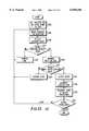
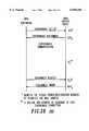
- FIG. 10is a flow chart illustrating one embodiment of steps for a network protocol method in accordance with the present invention.
- the initiation requestrequests a predetermined number of blocks to be transferred from the WSPD to the WDPD.
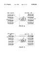
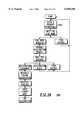
- FIG. 7, numeral 700is a block diagram of a WSPD in accordance with the present invention.
- the low complexity WSPDUpon sending or receiving an initiation request, initializing, and preparing N blocks of data, N a predetermined integer, for transmission, the low complexity WSPD efficiently accesses a radio resource in a wireless communication system and transmits the N blocks of data.
- the low complexity WSPD(702) includes a block assignment receiver unit (704) and an acknowledgment interpreter (706).
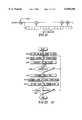
- the microwave oven interferencewill limit the achievable throughput in this system. Careful examination of the interference waveforms indicates that the microwave is not radiating power all of the time. Since the klystron is active only when the voltage of a half-wave rectified AC power input is greater than some value, interference is only present in a given 1 MHz channel for 40% or less of the time, with a periodic 60/50 Hz cycle. Depending on the center frequency of the channel, some interference patterns appear as two short spikes (1102) at the turn on or off points of the klystron. A spectrum analyzer screen capture shown in FIG. 11, numeral 1100, illustrates the interference modes that are commonly seen.
- the architecture of the In-Home RF Bus protocolis defined in terms of interfaces, devices, applications, and connections.
- the interfacesrefer to the physical media over which the data is communicated.
- Devicesdefine the end-points of the various interfaces.
- the applicationsfurnish the services provided to registered peripherals. Connections carry the data between a registered peripheral and the serving application.
- Legacy peripheralscover all devices that have traditionally been wired to a computer such as printers, scanners, and laptops. These devices may be connected by an emulated wired interface carried over the A-Interface to the personal computer. This emulated interface is referred to a the L-Interface or Legacy-Interface.
- the L-interfacemay be a PCI, RS-232, ISA, or Parallel Port.
- the wired voice & data networkrepresents a connection to the Public Switched Telephone Network, the Internet, a cable provider, or satellite network.
- Peripherals that wish to connect to the wired voice and data networkmust always go through an intermediate application. Two default applications are defined for this purpose, the POTS application and the PPP application.
- w cis the RF carrier frequency.
- the channel bit rate of 1.544 megabits per secondcorresponds to a symbol rate of 772 kilosymbols per second.
- the BA burstenables the dynamic allocation and duplexing features of the DTDMA/TDD channel, assigning the both the source and destination device at the beginning of each block transaction.
- the source and destination address fieldsmay either specify an access point or peripheral enabling downlink (access point to peripheral), uplink (peripheral to access point), or peer-to-peer (peripheral to peripheral) transfers.
- the BA fieldcontains general broadcast information to identify the system, the current transaction block, the current frame, and the RF channel of the next frame.
- the acknowledgment value, received from the destination peripheral in the previous frameis repeated as part of the BA field.
- the addresses, broadcast information, and acknowledgment fieldsare all protected by a 24-bit CRC. Furthermore these protected fields are preceded by differential encoding reference symbol (2-bits) and a synchronization word (32-bits). Table 2 defines the order and the content of the fields within the BA burst.
- Frequency hopping informationis communicated through the 8 bit "FH Word" data element contained in every BA.
- a unitcan read the current BA's FH Word to know which channel to hop to at the end of the current frame. This is essential before and during the registration process, because the unit is not synchronized with the base's FHP.
- the baseuses the data packet that accompanies the Registration Acknowledge packet to download the entire FHP into the unit.
- the unitthen does not have to read the BA field every frame to know where to hop to next, and can weather long periods of interference, such as might be expected as the unit goes in and out of range from the base.
- the unitcan now power down and "sleep" for long periods of time, awakening on the correct frequency channel by advancing the index into the FHP by the number of frames of sleep.
- This descriptionprovides specifications necessary to the design of the RF and IF transceiver sections of the access point and peripheral. First, requirements of the access point and peripheral receivers are specified.
- the input third order intercept point of both the access point and peripheral receivershall be greater than -16 dBm.
- the DA-TDMA systemassigns each block on an individual basis and allows all blocks to be immediately acknowledged. Assignments are based on connections to applications where each connection corresponds to a unique physical layer address. Within these connections, acknowledgements are used to mitigate the interference caused by microwave ovens and other impediments.
- the individual blocksmay be combined to form isochronous data streams from 1 to 992 kbps or asynchronous data packet up to 6141 octets long. Individual connections can be aggregated to form a full-duplex communications link which may be asymmetrical.
- a control connectionis used to manage the origination and termination of both types of transfers. The control connection is used to manage system parameters such as hopping patterns, devices IDs, etc.
- a peripheral contending on the systemwill monitor the BA bursts until a control block is detected.
- An asynchronous connectiontransfer an a periodic data packet between a peripheral device and application.
- the most common data type transferredare PPP encapsulated IP datagrams.
- Each asynchronous connectionis established during the registration process and is maintained for the duration a device is registered.
- the data packetis segmented by the source device into native payload blocks called asynchronous segments.
- the first segmentis a control segment followed by the requisite number of data segment.
- Ninety-two octets of a data packetmay be included in the control segment.
- Each subsequent data segmentmay carry 96 octets of the data.
- the final data segmentwill be padded will fill bits to form one complete block.
- the end of the data in the final segmentis specified in the initial control segment's Pad-Octets and Pad-Bits fields. See the information on Control Connection Extended Header for the form at of the initial control segment.
- a peripheral in the isochronous modemay support multiple number of isochronous connections differentiated by unique sub-addresses.
- Each isochronous connectionwill specify a fixed number blocks to transfer per IW and the direction of the transfer. The number of blocks determines the data rate for the transfer with one block per IW forming the fundamental data rate 32 kbps.
- Super-rate and sub-rate connectionsare also possible.
- a super-rate connectionis formed by transferring multiple blocks per IW giving a N ⁇ 32 kbps data-rate.
- Sub-ratesare formed by transferring one block every M IWs giving a 32/M kbps data-rate.
- the access pointshould assign a block to the peripheral's control connection in the next IW.
- An access point with control datasimply sends the information prior to the isochronous blocks.
- the connectionmay be terminated by either the peripheral or access point.
- the peripheralWhen terminated by the peripheral, the peripheral sends an asynchronous disconnect request to the access point.
- the access pointresponds with a disconnect order.
- the access pointWhen terminated by the access point, the access point simply sends an unsolicited disconnect order.
- the access pointis responsible for managing the systems resources and must enforce an admittance policy reserving bandwidth for retransmission's. When the capacity is exceeded, isochronous connections will be denied. The system's isochronous capacity is shared.
- Peripherals in either modemay receive messages, referred to as pages, during their scheduled IWs, referred to as both paging or polling intervals. All uplink and downlink messages during standby mode are addressed to the control connection.
- the DRX modeis intended to complement the asynchronous protocol by supporting units with varying data load and low delay requirements.
- the polled modemay be used to alleviate congestion by relegating all delay insensitive devices to infrequent polling.
- the polled modemay also be selected if the maximum delay must be bounded since a peripheral will have an opportunity to access the system every polling interval.
- the access pointdetermines whether a peripheral is assigned to a DRX or polled mode in order to balance the system's performance for all peripherals.
- the access pointmay send data to other peripherals at its discretion.
- the peripheralwill demodulate one block assignment, determine the message is for another user and return to low-power mode until the next paging interval.
- Control messagesare carried within the 96-octet data field of the payload burst. Every block within a control message will use the 32-bit Control Connection Extended Header reducing the available octets in the data field to 92. The coding of these remaining octets are defined below:
- Application Initialization Requestis used during service negotiation to initialize an application.
- the peripheralspecifies which application it would like to connect to and identifies it capabilities to the application server.
- the format of the information elementis in Table 31.
- the peripheralIn order for a peripheral to acquire a new system and access service the peripheral must be able to synchronize to an access point, reject access points that are not its own, and finally identify the purchaser's access point as its own.
- the purchaser's access point and peripheralare assumed to share a PIN which is unique to the new peripheral.
- the access point and peripheralare assumed to also share a PSK.
- the method for inserting the PIN and PSK into the access pointis left to the manufacturer's desecration.
- the peripheralIf the peripheral is dissatisfied with any Application Assignment, it make send up a subsequent Service Set-Up containing alternative application settings. This process will continue until the peripheral receives a set of parameters it is satisfied with or chooses not subscribe to the services of an application. Having reached that point, the peripheral ends the negotiation process by sending a Service Negotiation Complete containing the Application IDs of the application it has chosen to subscribe too. Omitted Application IDs are assumed to have been rejected and therefore the access point may release any previously negotiated resources associated with the rejected applications.
Landscapes
- Engineering & Computer Science (AREA)
- Computer Networks & Wireless Communication (AREA)
- Signal Processing (AREA)
- Mobile Radio Communication Systems (AREA)
Abstract
Description
I.sub.k =I.sub.k-1 cos[Δφ(X.sub.k,Y.sub.k)]-Q.sub.k-1 sin[Δφ(X.sub.k,Y.sub.k)]
Q.sub.k =I.sub.k-1 sin[Δφ(X.sub.k,Y.sub.k)]-Q.sub.k-1 cos[Δφ(X.sub.k,Y.sub.k)]
TABLE 1 ______________________________________ Modulator phase transitions for all input patterns. X.sub.k Y.sub.k DF(X.sub.k,Y.sub.k) ______________________________________ 0 0 +p/4 0 1 +3p/4 1 1 -3p/4 1 0 -p/4 ______________________________________
s(t)=i(t)*cos(ω.sub.c t)-q(t)*sin(ω.sub.c t)
TABLE 2 __________________________________________________________________________Block Assignment Burst Fields Bit Indices Fields Description (begin/end) Length __________________________________________________________________________Differential Encoding Provides a reference for the differential modulation. 0 1 2 bits Reference Symbol Synchronization The sync word is the followingbinary value 2 33 32 bit Word %00000101111101011100100111000110..sup.1 Block Count Specifies the number of the current block. It 34 34 5 bits incremented sequentially for each new frame taking on thevalues 0 through 31. Frame Count Specifies the number of the current frame. It 35 46 19 bits incremented sequentially for each new frame taking on thevalues 0 through 524287. It will not repeat for at least 35 hours. Acknowledgment Status of the transfer in the previous transaction 47 58 1 bit block. Set to 1 if it was successful and set to 0 if it was not. Next Frequency Specifies the channel of the next frame. 59 66 7 bits System ID A short ID, selected by the access point upon 67wer- 85 8 bits up, used to distinguish the system from it's neighbors. Source Address The address of the source device and respective 86 90 12 bits connection. Destination The address of the destination device and respective 91 97 12 bits Address connection. Reserved Reserved field must be encoded as 0. 98 107 10 bits CRC See Section 3.2.2.2 Error Detection 108 131 24 bits __________________________________________________________________________ .sup.1 The maximum sidelobe of the outof-phase autocorrelation and the merit factor, a function of the sum of the squares of the outof-phase autocorrelation, are commonly used to determine good synchronization words. The binary sequence %00000101111101011100100111000110 minimizes th maximum sidelobe and maximizes the merit factor over all 32bit sequences, #where only even (symbol) phase autocorrelation are considered.
TABLE 3 __________________________________________________________________________Payload Burst Fields Bit Indices Fields Description (begin/end) Length __________________________________________________________________________Differential Encoding Provides a reference for the differential modulation. 0 1 .sup. 2 bits Reference Symbol Synchronization The sync word is the followingbinary value 2 33 32 bit Word %00000101111101011100100111000110. System ID A short ID idential to the field in the previous BA 34rst. 41 .sup. 8 bits Scramble Mode Specifies whether the remaining fields in the 42rst 42 1 bit are scrambled by a pseudo random sequence. A value of 1 indicates that the fields are scrambled. Control Specifies whether the source peripheral requires 43 43 1 bit Connection control block. A value of 1 indicates a control Status message is pending. This field is not valid when the source device is an access point. Reserved Bits Must be encoded as 0. 44 44 .sup. 4 bits SBSN Sub-address Block Sequence Number 45 48 1 bit Extended Header Indicates that the header is extended into the 49yload 49 1 bit using the 3-octet control connection extended header format. A value of one indicates the header is extended. See section 3.3.1.2 Control Connection Extended Header. Data 96 octets of user data on dedicated connection. 502 817 768 bits octets on a control connection.) CRC See Error Detection 818 841 24 bits __________________________________________________________________________
TABLE 4 ______________________________________ ACKSEQ Codewords Color Code ACKSEQ ______________________________________ 0 SEQ-0 11000000110100001010011011111101 SEQ-1 10000000100111110011101101010110 NAK 01000000010011111001110110101011 1 SEQ-0 10101110101101111000001100000001 SEQ-1 11101110111110000001111010101010 NAK 00101110001010001011100001010111 2 SEQ-0 00011100000111101110110100000101 SEQ-1 01011100010100010111000010101110 NAK 10011100100000011101011001010011 3 SEQ-0 01110010011110011100100011111001 SEQ-1 00110010001101100101010101010010 NAK 11110010111001101111001110101111 4 SEQ-0 01111000011100100100011110100001 SEQ-1 00111000001111011101101000001010 NAK 11111000111011010111110011110111 5 SEQ-0 00010110000101010110001001011101 SEQ-1 01010110010110101111111111110110 NAK 10010110100010100101100100001011 6 SEQ-0 10100100101111000000110001011001 SEQ-1 11100100111100111001000111110010 NAK 00100100001000110011011100001111 7 SEQ-0 11001010110110110010100110100101 SEQ-1 10001010100101001011010000001110 NAK 01001010010001000001001011110011 8 SEQ-0 10110000101010110001001011101001 SEQ-1 11110000111001001000111101000010 NAK 00110000001101000010100110111111 9 SEQ-0 11011110110011000011011100010101 SEQ-1 10011110100000111010101010111110 NAK 01011110010100110000110001000011 10 SEQ-0 01101100011001010101100100010001 SEQ-1 00101100001010101100010010111010 NAK 11101100111110100110001001000111 11 SEQ-0 00000010000000100111110011101101 SEQ-1 01000010010011011110000101000110 NAK 10000010100111010100011110111011 12 SEQ-0 00001000000010011111001110110101 SEQ-1 01001000010001100110111000011110 NAK 10001000100101101100100011100011 13 SEQ-0 01100110011011101101011001001001 SEQ-1 00100110001000010100101111100010 NAK 11100110111100011110110100011111 14 SEQ-0 11010100110001111011100001001101 SEQ-1 10010100100010000010010111100110 NAK 01010100010110001000001100011011 15 SEQ-0 10111010101000001001110110110001 SEQ-1 11111010111011110000000000011010 NAK 00111010001111111010011011100111 16 SEQ-0 00100000001001111100111011010101 SEQ-1 01100000011010000101001101111110 NAK 10100000101110001111010110000011 17 SEQ-0 01001110010000001110101100101001 SEQ-1 00001110000011110111011010000010 NAK 11001110110111111101000001111111 18 SEQ-0 11111100111010011000010100101101 SEQ-1 10111100101001100001100010000110 NAK 01111100011101101011111001111011 19 SEQ-0 10010010100011101010000011010001 SEQ-1 11010010110000010011110101111010 NAK 00010010000100011001101110000111 20 SEQ-0 10011000100001010010111110001001 SEQ-1 11011000110010101011001000100010 NAK 00011000000110100001010011011111 21 SEQ-0 11110110111000100000101001110101 SEQ-1 10110110101011011001011111011110 NAK 01110110011111010011000100100011 22 SEQ-0 01000100010010110110010001110001 SEQ-1 00000100000001001111100111011010 NAK 11000100110101000101111100100111 23 SEQ-0 00101010001011000100000110001101 SEQ-1 01101010011000111101110000100110 NAK 10101010101100110111101011011011 24 SEQ-0 01010000010111000111101011000001 SEQ-1 00010000000100111110011101101010 NAK 11010000110000110100000110010111 25 SEQ-0 00111110001110110101111100111101 SEQ-1 01111110011101001100001010010110 NAK 10111110101001000110010001101011 26 SEQ-0 10001100100100100011000100111001 SEQ-1 11001100110111011010110010010010 NAK 00001100000011010000101001101111 27 SEQ-0 11100010111101010001010011000101 SEQ-1 10100010101110101000100101101110 NAK 01100010011010100010111110010011 28 SEQ-0 11101000111111101001101110011101 SEQ-1 10101000101100010000011000110110 NAK 01101000011000011010000011001011 29 SEQ-0 10000110100110011011111001100001 SEQ-1 11000110110101100010001111001010 NAK 00000110000001101000010100110111 30 SEQ-0 00110100001100001101000001100101 SEQ-1 01110100011111110100110111001110 NAK 10110100101011111110101100110011 31 SEQ-0 01011010010101111111010110011001 SEQ-1 00011010000110000110100000110010 NAK 11011010110010001100111011001111 ______________________________________
TABLE 5 ______________________________________ Information bits that are systematically encoded to form the ACKSEQ. Bit Source ______________________________________ 0SYSTEM ID bit0 1SYSTEM ID bit1 2SYSTEM ID bit2 3SYSTEM ID bit3 4SYSTEM ID bit4 5 1 for NAK, 1 for SEQ-0, 0 for SEQ-1 6 1 for NAK, 0 for SEQ-0, 1 for SEQ-1 ______________________________________
TABLE 6 ______________________________________ ACKSEQ generation table. ACKSEQ Bit XCR of Information Bits ______________________________________ 0 5 1 6 2 6+5+3+2+0 3 5+5+2+1+0 4 6+5+3+2+1+0 5 5+4+1+0 6 6+5+2+1+0 7 5+1+0 8 6+2+1+0 9 6+5+1 10 5+3+0 11 6+4+1 12 6+3 13 6+5+4+3+2+0 14 4+2+1 15 5+3+2 16 6+4+3+0 17 6+4+3+2+1+0 18 6+4+1+0 19 6+3+1 20 6+5+4+3 21 4+3+2+0 22 5+4+3+1+0 23 6+5+4+2+1 24 none (always equals zero).sup.1 25 0 26 1+0 27 2+1+0 28 3+2+1 29 4+3+2+0 30 5+4+3+1+0 31 6+5+4+2+1 ______________________________________ .sup.1 While this bit may be removed without affecting the minimum distance of the code, it is left as is to have an even number of bits for the QPSK modulation. It is not made a function of the information bits because the cydic nature of the code would be lost.
TABLE 7 ______________________________________ Frequency Hopping Parameters Parameter/Field Description Value (typical U.S.) ______________________________________ q # of frequency channels max 128 (79) N max 128 (79) K # of patterns max 128 (78) FH Word frequency channel, 0..q-1 8 bits FHP list of frequency channels, N * 8 bits indexed 0..N-1 ______________________________________
TABLE 8 ______________________________________ Reserved Addresses Address (Binary) Purpose ______________________________________ %000000000000 The "null" address indicates that the source or destination device is the access point %1111111XXXXX Reserved for contention access. The 5 sub-addresses associated with this address specify the various persistence modes and priority levels. %1010101XXXXX Reserved for pre-registration. The sub-address field will be selected at random by the registering peripheral providing 32 independent pre-registration addresses. ______________________________________
TABLE 9 __________________________________________________________________________Control Connection Extended Header Extender Header Bit Indices Fields Description (begin/end) Length __________________________________________________________________________Multiple Indicates that this is a single block transmission 50 50 1 bit Block and does not require any additional blocks to complete the transmission. A value of 0 indicates a single block. PPP Indicates that the true destination is 51sed 51 1 bit within the encapsulated Point-to-Point Protocol Packet Reservation Used to distinguish between retried reservation 52 52 1 bit Sequence requests from a single device Number Reserved Reserved. Encoded as 1 53 1 bit Source Source address to used for subsequent blocks 54 65 12 bits Address of asynchronous packet. The source address uniquely identifies the corresponding service and format of the enclosed data. Remaining Number of remaining blocks. A value of N implies 66 71 6 bits Blocks a packet length of (93+96·N) octets. May take on thevalue 0 throught 63. A maximum of packet length of 6141 octets The single block bit must be set for one block packets. Pad Bits Specifies the number of padding bits in the final 72 74 3 bits octet. (The final octet precedes the first pad octet) May take on thevalues 0 through 7. Pad Octets Specifies the number of padding octets in the 81 7 bits final block. May take on thevalues 0 through 95. Data Format of the data is determined by the Source 82 817 93 octets Address above. __________________________________________________________________________
TABLE 10 ______________________________________ Contention Address Format Fields Description Length ______________________________________ Fundamental Fundamental portion of the contention address. 7 bits Address Must be encoding as binary 51010101. Restricted A value of 1 indicates that only registering 1 bit Status terminals may access this connection block. Reserved Must be encoded as 0. 1 bits Persistence Species the persistence level used by the 3 bits Level peripheral in the current block. Value Level %000 => 1 %001 => 1/2 %010 => 1/4 %011 => 1/8 %100 => 1/16 %101 => 1/32 %110 => 1/64 %111 => 1/128 ______________________________________
TABLE 11 ______________________________________ Octet field Description Length ______________________________________ Protocol Marks the revision of the In-Home RF Bus 1 octet Version control message protocol.Version 0 is defined by this document. Messasge Identifies the control message which 1 octet Type defines the purpose as well as the required and optional information elements contained. The available message types and their cor- responding code-points are defined in section 3.3.5.3. Message Length of the control message in blocks. 1 octet Length This field may take on thevalue 1 to 255. The value in this field is repeated in every block of a multi-block control message. Message Index of the current message block. This 1 octet Block field may take on thevalues 1 through 255. The first block in a multi-block control message is numbered 1. Information Information elements are defined by the 88 octets Elements message type above. Messages may specify both mandatory and optional elements. Section 3.3.5.4 Control Message Formats defines the mandatory and optional elements per message. ______________________________________
TABLE 12 ______________________________________ Value Message Direction Reference ______________________________________ 0 Registration Request Uplink 3.3.5.4.1 1Registration Assignment Downlink 0 2 Registration Reject Uplink 3.3.5.4.3 3 Authenticity Challenge Bi-directional 0 4 Authenticity Response Bi-directional 0 5 Service Set-up Uplink 3.3.5.4.6 6 Service Assignment Downlink 3.3.5.4.7 7 ServiceNegotiation Complete Uplink 0 8 Isochronous Set-up Uplink 3.3.5.4.9 9Isochronous Downlink 0 Assignment/Announcement 10Isochronous Reject Downlink 0 11Disconnect Request Uplink 0 12Disconnect Order Downlink 0 14 Application Information Bi-directional 3.3.5.4.14 15 Null Bi-directional 3.3.5.4.15 ______________________________________
TABLE 13 ______________________________________ Information Element Reference Type Length ______________________________________Random M 4 Number ofConnections M 1PIN M 12 ControlSegment Pace M 1Language Identifier M 1 Fill Pattern M 69 ______________________________________
TABLE 14 ______________________________________ Information Element Reference Type Length ______________________________________Random M 4Fundamental Address M 2 ScrambleCode Index M 2 Frequency Hopping Pattern M 80 SystemSpecific ID O 14 Peripheral ID O 6 ControlChannel Access O 1 Fill Pattern M 81 ______________________________________
TABLE 15 ______________________________________ Information Element Reference Type Length ______________________________________Random M 4Cause M 4Language Identifier M 1 Fill Pattern M 79 ______________________________________
TABLE 16 ______________________________________ Information Element Reference Type Length ______________________________________ Random Challenge M 8 Fill Pattern M 80 ______________________________________
TABLE 17 ______________________________________ Information Element Reference Type Length ______________________________________ Random Challenge M 8 Challenge Response M 8 Fill Pattern M 72 ______________________________________
TABLE 18 ______________________________________ Information Element Reference Type Length ______________________________________ Applications Initialization Request O * (multiple instances) ______________________________________
TABLE 19 ______________________________________ Information Element Reference Type Length ______________________________________Standby Mode M 9 SystemSpecific ID M 12Peripheral ID M 4 Application Assignment (multiple O * instances) ______________________________________
TABLE 20 ______________________________________ Information Element Reference Type Length ______________________________________ SystemSpecific ID M 12Peripheral ID M 4 Application Identifier (Multiple)O 3 Fill Pattern M * ______________________________________
TABLE 21 ______________________________________ Information Element Reference Type Length ______________________________________Application Identifier M 1 IsochronousConnection Request M 1 Isochronous Connection Request O 3 (Multiple) Application Information O * Fill Pattern M * ______________________________________
TABLE 22 ______________________________________ Information Element Reference Type Length ______________________________________Application Identifier M 1Frame M 3 Frame OffsetM 1Connection M 2 Connection (Multiple)M 4 Application Information O * Fill Pattern M * ______________________________________
TABLE 23 ______________________________________ Information Element Reference Type Length ______________________________________Application Identifier M 1 IsochronousConnection Request M 1 Isochronous Connection Request O 3 (Multiple) Fill Pattern M * ______________________________________
TABLE 24 ______________________________________ Information Element Reference Type Length ______________________________________Application Identifier M 1Connection M 2 Connection (multiple)O 4 Application Information O * Fill Pattern M * ______________________________________
TABLE 25 ______________________________________ Information Element Reference Type Length ______________________________________Application Identifier M 1Isochronous Frame M 2Connection M 2 Connection (multiple)O 4 Application Information O * Fill Pattern M * ______________________________________
TABLE 26 ______________________________________ Information Element Reference Type Length ______________________________________Application Identifier M 1 Application Information O * Fill Pattern M * ______________________________________
TABLE 27 ______________________________________ Information Element Reference Type Length ______________________________________ SystemSpecific ID M 12Peripheral ID M 4 Fill Pattern M 73 ______________________________________
TABLE 28 ______________________________________ Value Message Direction Reference ______________________________________ 0 Random 3.3.5.5.1 1 Number of Connections 3.3.5.5.2 2 PIN 3.3.5.5.3 3 Control Segment Pace 3.3.5.5.4 4 Null Field 3.3.5.5.5 5 Fundamental Address 3.3.5.5.6 6 System ID 3.3.5.5.7 7 Scramble Code Index 3.3.5.5.8 8 Control Channel Access 3.3.5.5.9 9 Frequency Hopping Pattern 3.3.5.5.10 10 Fill Pattern 3.3.5.5.11 11 System Specific ID 3.3.5.5.12 12 Peripheral ID 3.3.5.5.13 13 Application Initialization 3.3.5.5.14Request 14 Standby Mode 3.3.5.5.15 15 Application Assignment 3.3.5.5.16 16 Application Identifier 3.3.5.5.17 17 Isochronous Connection 3.3.5.5.18 Request 18 Application Information 3.3.5.5.19 19 Frame 3.3.5.5.20 20 Frame Offset 3.3.5.5.21 21 Isochronous Connection 3.3.5.5.22 22 Cause 3.3.5.5.23 ______________________________________
TABLE 29 ______________________________________ Value Interpretation ______________________________________ 0 The peripheral supports the full-rate pace. 1 The peripheral supports the medium-rate pace. 2 Ther peripheral supports the low-rate pace. ______________________________________
TABLE 30 ______________________________________ Fundamental Address Assignment Extended Header Fields Description Length ______________________________________ Sub-Address Number of LSBs in the address that 3 bit Depth represent sub-address space. A value may range from 0 to 5. Reserved Encoded as one. 1bit Address A 12 bit value between 0 and 4095. 12 bit ______________________________________
TABLE 31 ______________________________________ Application Initialization Request Format Fields Description Length ______________________________________ Application Uniquely defines the application to 4 octets Specific Identifier connect too. Application As required by theapplication 0 to 82 octets Information definition. ______________________________________
TABLE 32 ______________________________________ Standby Mode Format Fields Description Length ______________________________________ Mode Sets the standby mode to either polled or 1 octet discontinuous reception. A value of 1 indicates a poll a value of 0 indicates discontinuous reception. Period Number of frames between pages or polls. 3 octets May take on thevalues 0 through 524287. Allows for a maximum standby of 3.5 hours and a minimum of 24 milliseconds. Frame Offset Specifies the block in the frame of the .1 octets paging interval. May take on thevalues 0 to 30. Start Frame The frame at which thefirst paging interval 3 octets will begin. May take on thevalues 0 through 524287. Equivalent to the 19 bit frame number in the block assignment burst. Re-registration Specifies the multiple ofpaging periods 1 octet Period after which the peripheral must re-register with the system. A value of 0 indicates that re-registrations are not required. ______________________________________
TABLE 33 ______________________________________ Application Assignment Format Fields Description Length ______________________________________ Application Assigns a short 8-bit identifier to the 1 octet Identifier application for further reference. The shorten 8-bit identifier is used for a subsequent reference and is unique to a particular access point. Application Uniquely defines the application. 4 octets Specific Identifier Application As required by the application definition. 0 to 82 octets Information ______________________________________
TABLE 34 ______________________________________ Isochronous Connection Request Fields Description Length ______________________________________ Direction A value of 0 indicates an uplink connection is 1 bit required, from peripheral to access point. A value of 1 indicates a downlink connection is required, from access point to peripheral. Mode A value of 0 indicates a sub-rate connection is 1 bit requested while a value of 1 denotes a super-rate connection is Reserved Reserved. Must be encoded as 0. 1 bit Rate For sub-rate traffic, the field specifies thenumber 5 bits of frames between blocks and may take on thevalues 1 through 5 providing a 1 to 16 Kbps data-rate. For super-rate traffic, the field specifies the number of blocks per frame and may take on thevalues 1 through 31 providing a 32 to 992 Kbps data rate. ______________________________________
TABLE 35 ______________________________________ Application Information Format Fields Description Length ______________________________________ Application Assigns a short 8-bit identifier to the 1 octet Identifier application for further reference. The shorten 8-bit identifier is used for subsequent reference and is unique to a particular access point. Application As required by the application definition. 0 to 82 octets Information ______________________________________
TABLE 36 ______________________________________ Cause Values Value Interpretation ______________________________________ 0 "Peripheral has not been registered with this access point." 1 "Bandwidth is unavailable." Others Reserved. ______________________________________
Claims (15)
Priority Applications (4)
| Application Number | Priority Date | Filing Date | Title |
|---|---|---|---|
| US08/953,948US6058106A (en) | 1997-10-20 | 1997-10-20 | Network protocol method, access point device and peripheral devices for providing for an efficient centrally coordinated peer-to-peer wireless communications network |
| PCT/US1998/014015WO1999021095A1 (en) | 1997-10-20 | 1998-07-07 | Network protocol method for providing a centrally coordinated peer-to-peer wireless communications network |
| TW087113745ATW432851B (en) | 1997-10-20 | 1998-08-20 | Network protocol method, access point device and peripheral devices for providing for an efficient centrally coordinated peer-to-peer wireless communications network |
| FR9812648AFR2770068A1 (en) | 1997-10-20 | 1998-10-09 | Network protocol for centrally coordinated point-to-point wireless telecommunications network |
Applications Claiming Priority (1)
| Application Number | Priority Date | Filing Date | Title |
|---|---|---|---|
| US08/953,948US6058106A (en) | 1997-10-20 | 1997-10-20 | Network protocol method, access point device and peripheral devices for providing for an efficient centrally coordinated peer-to-peer wireless communications network |
Publications (1)
| Publication Number | Publication Date |
|---|---|
| US6058106Atrue US6058106A (en) | 2000-05-02 |
Family
ID=25494758
Family Applications (1)
| Application Number | Title | Priority Date | Filing Date |
|---|---|---|---|
| US08/953,948Expired - LifetimeUS6058106A (en) | 1997-10-20 | 1997-10-20 | Network protocol method, access point device and peripheral devices for providing for an efficient centrally coordinated peer-to-peer wireless communications network |
Country Status (4)
| Country | Link |
|---|---|
| US (1) | US6058106A (en) |
| FR (1) | FR2770068A1 (en) |
| TW (1) | TW432851B (en) |
| WO (1) | WO1999021095A1 (en) |
Cited By (187)
| Publication number | Priority date | Publication date | Assignee | Title |
|---|---|---|---|---|
| US6229807B1 (en)* | 1998-02-04 | 2001-05-08 | Frederic Bauchot | Process of monitoring the activity status of terminals in a digital communication system |
| US20010033550A1 (en)* | 2000-01-28 | 2001-10-25 | Banwell Thomas Clyde | Physical layer auto-discovery for management of network elements |
| US20010043615A1 (en)* | 2000-02-26 | 2001-11-22 | Park Jeong-Hoon | Apparatus for transmitting/receiving a bit stream in a network and method therefor |
| US20020009053A1 (en)* | 1999-01-19 | 2002-01-24 | Kai Sjoblom | Controlled data network error recovery |
| US20020022483A1 (en)* | 2000-04-18 | 2002-02-21 | Wayport, Inc. | Distributed network communication system which allows multiple wireless service providers to share a common network infrastructure |
| US6374082B1 (en)* | 1998-06-02 | 2002-04-16 | Eastman Kodak Company | RF wireless communication system operating in periodic noise environments |
| US20020058499A1 (en)* | 2000-06-27 | 2002-05-16 | Ortiz Luis M. | Systems, methods and apparatuses for brokering data between wireless devices and data rendering devices |
| US20020058502A1 (en)* | 2000-11-13 | 2002-05-16 | Peter Stanforth | Ad hoc peer-to-peer mobile radio access system interfaced to the PSTN and cellular networks |
| US20020085526A1 (en)* | 2000-11-08 | 2002-07-04 | Belcea John M. | Time division protocol for an ad-hoc, peer-to-peer radio network having coordinating channel access to shared parallel data channels with separate reservation channel |
| US20020085631A1 (en)* | 2000-08-18 | 2002-07-04 | Engwer Darwin A. | Method, apparatus, and system for managing data compression in a wireless network |
| US20020091795A1 (en)* | 2001-01-05 | 2002-07-11 | Michael Yip | Method and system of aggregate multiple VLANs in a metropolitan area network |
| US20020090004A1 (en)* | 2001-01-09 | 2002-07-11 | Motorola, Inc. | Method for scheduling and allocating data transmissions in a broad-band communications system |
| US20020104044A1 (en)* | 2001-01-26 | 2002-08-01 | Penick Matthew W. | Method of optimizing the use of radio devices in a computing system |
| US6430395B2 (en) | 2000-04-07 | 2002-08-06 | Commil Ltd. | Wireless private branch exchange (WPBX) and communicating between mobile units and base stations |
| WO2002063914A1 (en)* | 2001-02-07 | 2002-08-15 | Telefonaktiebolaget Lm Ercisson (Publ) | Methods and systems for improved automatic retransmission query (arq) schemes in radiocommunication systems |
| US20020124066A1 (en)* | 2000-12-15 | 2002-09-05 | International Business Machines Corporation | Method and system for unambiguous addressability in a distributed application framework in which duplicate network addresses exist across multiple customer networks |
| WO2002069654A1 (en)* | 2001-02-27 | 2002-09-06 | Motorola, Inc. | A method and apparatus for peer to peer communication over an inherently master slave interface |
| US20020129165A1 (en)* | 2001-03-12 | 2002-09-12 | Dingsor Andrew D. | Network address translation and port mapping |
| US20020138622A1 (en)* | 2001-03-21 | 2002-09-26 | Motorola, Inc. | Apparatus and method of using long lived addresses in a private network for push messaging to mobile devices |
| US6463475B1 (en)* | 1997-09-26 | 2002-10-08 | 3Com Corporation | Method and device for tunnel switching |
| US6466587B1 (en)* | 1998-02-23 | 2002-10-15 | Sony Corporation | Wireless transmitting method |
| US20020172217A1 (en)* | 2001-05-21 | 2002-11-21 | Kadaba Srinivas R. | Multiple mode data communication system and method and forward and/or reverse link control channel structure |
| US20030031152A1 (en)* | 2000-02-23 | 2003-02-13 | Wataru Gohda | Asynchronous transmission method |
| US20030040316A1 (en)* | 2001-03-22 | 2003-02-27 | Peter Stanforth | Prioritized-routing for an ad-hoc, peer-to-peer, mobile radio access system based on battery-power levels and type of service |
| US6529525B1 (en)* | 2000-05-19 | 2003-03-04 | Motorola, Inc. | Method for supporting acknowledged transport layer protocols in GPRS/edge host application |
| US6535918B1 (en)* | 1998-09-22 | 2003-03-18 | Qualcomm Incorporated | Interface between standard terminal equipment unit and high speed wireless link |
| US20030060231A1 (en)* | 2000-09-19 | 2003-03-27 | Bruno Bozionek | Method for operating a communications system |
| US20030069003A1 (en)* | 2001-10-10 | 2003-04-10 | Anne Morgan | Sequence number calculation and authentication in a communications system |
| US6567396B1 (en)* | 1999-12-13 | 2003-05-20 | Telefonaktiebolaget Lm Ericsson (Publ) | Adaptive throughput in packet data communication systems using idle time slot scheduling |
| US20030099221A1 (en)* | 2001-11-28 | 2003-05-29 | Sokwoo Rhee | Network protocol |
| US20030103460A1 (en)* | 2001-12-05 | 2003-06-05 | Sanjay Kamath | Method and system for flow control between a base station controller and a base transceiver station |
| US20030110126A1 (en)* | 2001-12-10 | 2003-06-12 | Dunkeld Bryan C. | System & method for unique digital asset identification and transaction management |
| US20030131299A1 (en)* | 2002-01-05 | 2003-07-10 | Lg Electronics Inc. | Method and apparatus for transmitting acknowledgement signals |
| US20030135552A1 (en)* | 2002-01-14 | 2003-07-17 | Blackstock Michael A. | Method for discovering and discriminating devices on local collaborative networks to facilitate collaboration among users |
| US20030133422A1 (en)* | 2002-01-11 | 2003-07-17 | Harry Bims | Mobility support via routing |
| US20030145064A1 (en)* | 2002-01-28 | 2003-07-31 | Hsu Raymond T. | Method and apparatus for negotiation of transmission parameters for broadcast/multicast services |
| US6603737B1 (en)* | 1997-02-14 | 2003-08-05 | Canon Kabushiki Kaisha | Data transmission apparatus, system and method, and image processing apparatus |
| US6615161B1 (en)* | 1998-07-08 | 2003-09-02 | International Business Machines Corporation | Method and apparatus for adjusting an interval of polling a peripheral device in response to changes in the status and/or reliability of receiving traps |
| US20030167319A1 (en)* | 2001-08-08 | 2003-09-04 | Prema Venkatesulu | Performance of lifetest using CMTS as a proxy |
| WO2003075168A1 (en)* | 2002-03-01 | 2003-09-12 | Net2Printer, Inc. | A system for peer-to-peer transport of documents |
| US20030190958A1 (en)* | 2002-04-08 | 2003-10-09 | Paulsen Craig A. | Gaming apparatus with an optical wireless system |
| US20030189908A1 (en)* | 2002-04-08 | 2003-10-09 | Chia-Chee Kuan | Determining the state of a station in a local area network |
| US20030193895A1 (en)* | 2000-08-18 | 2003-10-16 | Engwer Darwin A. | Seamless roaming options in an IEEE 802.11 compliant network |
| US20030198184A1 (en)* | 2001-08-31 | 2003-10-23 | Joe Huang | Method of dynamically determining real-time multimedia streaming rate over a communications networks |
| US6640325B1 (en)* | 1999-06-04 | 2003-10-28 | Advanced Micro Devices, Inc. | Immediate negative acknowledgement for a communication network |
| US6647409B1 (en)* | 1999-07-13 | 2003-11-11 | Microsoft Corporation | Maintaining a sliding view of server based data on a handheld personal computer |
| US20030210796A1 (en)* | 2002-01-25 | 2003-11-13 | Mccarty William A. | Wired, wireless, infrared, and powerline audio entertainment systems |
| US20030227893A1 (en)* | 2002-06-05 | 2003-12-11 | Zeljko Bajic | Virtual switch |
| US20040019641A1 (en)* | 2002-07-25 | 2004-01-29 | Bartram Linda Ruth | Method for context based discovery and filtering of portable collaborative networks |
| US6687735B1 (en) | 2000-05-30 | 2004-02-03 | Tranceive Technologies, Inc. | Method and apparatus for balancing distributed applications |
| US6717949B1 (en)* | 1998-08-31 | 2004-04-06 | International Business Machines Corporation | System and method for IP network address translation using selective masquerade |
| US20040093518A1 (en)* | 2002-11-12 | 2004-05-13 | An Feng | Enforcing data protection legislation in Web data services |
| US20040114534A1 (en)* | 2002-12-16 | 2004-06-17 | Mathilde Benveniste | Traffic specifications for polling requests of periodic sources |
| US20040117635A1 (en)* | 2002-12-11 | 2004-06-17 | Jeyhan Karaoguz | Secure legacy media peripheral association with authentication in a media exchange network |
| US6760318B1 (en) | 2002-01-11 | 2004-07-06 | Airflow Networks | Receiver diversity in a communication system |
| US20040141472A1 (en)* | 2003-01-16 | 2004-07-22 | Wassim Haddad | Wireless LAN |
| US6772331B1 (en)* | 1999-05-21 | 2004-08-03 | International Business Machines Corporation | Method and apparatus for exclusively pairing wireless devices |
| US20040160957A1 (en)* | 2003-02-14 | 2004-08-19 | Coffman Stephen Blaine | Wireless datagram transaction protocol system |
| US20040162076A1 (en)* | 2003-02-14 | 2004-08-19 | Atul Chowdry | System and method for simplified secure universal access and control of remote networked electronic resources for the purposes of assigning and coordinationg complex electronic tasks |
| US20040167958A1 (en)* | 1999-11-03 | 2004-08-26 | Stewart Brett B. | Distributed network communication system which enables multiple network providers to use a common distributed network infrastructure |
| US6788658B1 (en) | 2002-01-11 | 2004-09-07 | Airflow Networks | Wireless communication system architecture having split MAC layer |
| US20040190523A1 (en)* | 2001-08-22 | 2004-09-30 | Christina Gessner | Method and radio sation for transmitting data packets in a radio-communication system |
| US20040254960A1 (en)* | 2003-06-10 | 2004-12-16 | Scaturro Paul E. | System and method for delivering video and music files over network |
| US6839776B2 (en)* | 1998-08-20 | 2005-01-04 | Intel Corporation | Authenticating peripherals based on a predetermined code |
| US6842433B2 (en)* | 2001-04-24 | 2005-01-11 | Wideray Corporation | System and method for communicating information from a computerized distributor to portable computing devices |
| US20050025188A1 (en)* | 2001-11-08 | 2005-02-03 | Keiko Numakura | Wireless communication method and mobile terminal used therefor |
| US20050027892A1 (en)* | 1999-11-11 | 2005-02-03 | Miralink Corporation | Flexible remote data mirroring |
| US20050037787A1 (en)* | 2003-06-27 | 2005-02-17 | Rosett-Wireless Corporation | Wireless intelligent portable-server system (WIPSS) |
| US20050037789A1 (en)* | 2003-06-05 | 2005-02-17 | Sokwoo Rhee | Protocol for configuring a wireless network |
| US6862448B1 (en) | 2002-01-11 | 2005-03-01 | Broadcom Corporation | Token-based receiver diversity |
| US20050058144A1 (en)* | 2000-02-18 | 2005-03-17 | Arun Ayyagari | Extending access to a device in a limited connectivity network to devices residing outside the limited connectivity network |
| US20050063525A1 (en)* | 2000-06-29 | 2005-03-24 | Ching Yi Lin | Phone appliance with display screen and methods of using the same |
| US6873839B2 (en) | 2000-11-13 | 2005-03-29 | Meshnetworks, Inc. | Prioritized-routing for an ad-hoc, peer-to-peer, mobile radio access system |
| US20050090273A1 (en)* | 2003-08-08 | 2005-04-28 | Haipeng Jin | Header compression enhancement for broadcast/multicast services |
| US6891807B2 (en) | 2003-01-13 | 2005-05-10 | America Online, Incorporated | Time based wireless access provisioning |
| US6894988B1 (en)* | 1999-09-29 | 2005-05-17 | Intel Corporation | Wireless apparatus having multiple coordinated transceivers for multiple wireless communication protocols |
| US20050122921A1 (en)* | 2003-12-04 | 2005-06-09 | Cheong-Jeong Seo | Apparatus and method for registering wireless terminals with access point through wireless network |
| US20050132080A1 (en)* | 2000-10-31 | 2005-06-16 | Millennial Net, A Massachusetts Corporation | Coordinating protocol for a multi-processor system |
| US20050130646A1 (en)* | 2001-12-26 | 2005-06-16 | Bellsouth Intellectual Property Corporation | Auto sensing home base station for mobile telephone with remote answering capabilities |
| US6914905B1 (en) | 2000-06-16 | 2005-07-05 | Extreme Networks, Inc. | Method and system for VLAN aggregation |
| US20050184154A1 (en)* | 2004-02-25 | 2005-08-25 | Matsushita Electric Industrial Co., Ltd. | Wireless communication medium processing apparatus and wireless communication medium processing system |
| US20050235112A1 (en)* | 1999-04-06 | 2005-10-20 | Microsoft Corporation | Method and system for handling streaming information |
| USRE38902E1 (en)* | 1998-04-23 | 2005-11-29 | Lucent Technologies Inc. | System and method for network address translation as an external service in the access server of a service provider |
| US20060105718A1 (en)* | 2004-11-12 | 2006-05-18 | Interdigital Technology Corporation | Method and apparatus for detecting and selectively utilizing peripheral devices |
| US20060104253A1 (en)* | 2003-09-30 | 2006-05-18 | Douglas Bretton L | Method and apparatus for cell identification in wireless data networks |
| US20060106933A1 (en)* | 2002-09-16 | 2006-05-18 | Jingnan Huang | Method for connecting devices in dynamic family networking |
| US20060111129A1 (en)* | 2004-10-18 | 2006-05-25 | Lg Electronics Inc. | Method of transmitting feedback information in an orthogononal frequency division multiplexing (OFDM)/ OFDM access (OFDMA) mobile communication system |
| US20060135145A1 (en)* | 2004-12-17 | 2006-06-22 | Bbnt Solutions Llc | Methods and apparatus for reduced energy communication in an ad hoc network |
| US7082114B1 (en)* | 2000-08-18 | 2006-07-25 | Nortel Networks Limited | System and method for a wireless unit acquiring a new internet protocol address when roaming between two subnets |
| US20060203890A1 (en)* | 2001-05-02 | 2006-09-14 | Oki Electric Industry Co., Ltd. | Radio LAN system implementing simultaneous communication with different types of information and communication method for the same |
| US20060229083A1 (en)* | 2004-12-17 | 2006-10-12 | Bbn Technologies Corp. | Methods and apparatus for reduced energy communication in an ad hoc network |
| US7130609B2 (en) | 1999-03-15 | 2006-10-31 | Bellsouth Intellectual Property Corp. | Wireless backup telephone device and associated support system |
| WO2006047339A3 (en)* | 2004-10-22 | 2006-11-02 | Utstarcom Inc | Encoding and error correction system for enhanced performance of legacy communications networks |
| US20060248158A1 (en)* | 2003-05-30 | 2006-11-02 | Sam-Chul Ha | Home network system |
| US20060251086A1 (en)* | 2003-05-30 | 2006-11-09 | Sam-Chul Ha | Home network system |
| WO2006120388A1 (en)* | 2005-05-12 | 2006-11-16 | Nokia Siemens Networks Gmbh & Co. Kg | A method of controlling interference between communication terminals |
| US20060276216A1 (en)* | 2005-06-01 | 2006-12-07 | Jason Tongen | Apparatus and methods for information handling system with dynamic output power |
| US7149514B1 (en) | 1997-07-30 | 2006-12-12 | Bellsouth Intellectual Property Corp. | Cellular docking station |
| US7149511B1 (en) | 2000-08-31 | 2006-12-12 | Rosetta-Wireless Corporation | Wireless intelligent personal server |
| US7149196B1 (en) | 2002-01-11 | 2006-12-12 | Broadcom Corporation | Location tracking in a wireless communication system using power levels of packets received by repeaters |
| US20060285579A1 (en)* | 2005-06-01 | 2006-12-21 | Sokwoo Rhee | Communicating over a wireless network |
| US20070019615A1 (en)* | 2003-05-30 | 2007-01-25 | Seung-Myun Baek | Home network system |
| US20070025368A1 (en)* | 2003-05-30 | 2007-02-01 | Lg Electronics, Inc. | Home network system |
| US20070030838A1 (en)* | 2005-08-05 | 2007-02-08 | Nokia Corporation | Power control for gated uplink control channel |
| US20070041378A1 (en)* | 2004-12-27 | 2007-02-22 | Bin Chul Ihm | Method of transmitting feedback information using an extended subheader |
| US7194083B1 (en) | 2002-07-15 | 2007-03-20 | Bellsouth Intellectual Property Corporation | System and method for interfacing plain old telephone system (POTS) devices with cellular networks |
| US20070070983A1 (en)* | 2005-09-28 | 2007-03-29 | Bbn Technologies Corp. | Methods and apparatus for improved efficiency communication |
| US20070116052A1 (en)* | 2005-10-21 | 2007-05-24 | Yanbin Yu | Encoding and error correction system for enhanced performance of legacy communications networks |
| US20070136476A1 (en)* | 2005-12-12 | 2007-06-14 | Isaac Rubinstein | Controlled peer-to-peer network |
| US20070149204A1 (en)* | 2003-01-31 | 2007-06-28 | Bbn Technologies Corp. | Systems and methods for three dimensional antenna selection and power control in an ad-hoc wireless network |
| US20070195730A1 (en)* | 2004-03-09 | 2007-08-23 | Matsushita Electric Industrial Co., Ltd. | Random Access Method And Radio Communciation Terminal Device |
| US20070223418A1 (en)* | 2003-04-03 | 2007-09-27 | Chia-Chee Kuan | Determining the state of a station in a local area network |
| US20070233879A1 (en)* | 2005-10-07 | 2007-10-04 | Steven Woods | System and method for advertisement identification, selection, and distribution involving a peer-to-peer network |
| US7280495B1 (en) | 2000-08-18 | 2007-10-09 | Nortel Networks Limited | Reliable broadcast protocol in a wireless local area network |
| US20070248052A1 (en)* | 2006-04-21 | 2007-10-25 | Shirish Nagaraj | Method to control the effects of out-of-cell interference in a wireless cellular system using backhaul transmission of decoded data and formats |
| US7290278B2 (en) | 2003-10-02 | 2007-10-30 | Aol Llc, A Delaware Limited Liability Company | Identity based service system |
| US7308279B1 (en) | 2000-08-18 | 2007-12-11 | Nortel Networks Limited | Dynamic power level control on transmitted messages in a wireless LAN |
| US7308233B2 (en) | 2002-10-10 | 2007-12-11 | Aster Wireless | System employing wideband wireless communication with super cycle detection |
| US20080049696A1 (en)* | 1995-06-06 | 2008-02-28 | Stewart Brett B | Method and apparatus for geographic-based communications service |
| US7339892B1 (en) | 2000-08-18 | 2008-03-04 | Nortel Networks Limited | System and method for dynamic control of data packet fragmentation threshold in a wireless network |
| US20080057294A1 (en)* | 2006-09-01 | 2008-03-06 | Fina Technology, Inc. | High impact polystyrene tile |
| US20080123868A1 (en)* | 2002-01-25 | 2008-05-29 | Ksc Industries, Inc. | Wired, wireless, infrared, and powerline audio entertainment systems |
| US20080194251A1 (en)* | 1997-07-30 | 2008-08-14 | Steven Tischer | Apparatus and method for providing communications and connection-oriented services to devices |
| US20080192769A1 (en)* | 1997-07-30 | 2008-08-14 | Steven Tischer | Apparatus and method for prioritizing communications between devices |
| US20080207328A1 (en)* | 2007-02-23 | 2008-08-28 | Neoedge Networks, Inc. | Interstitial advertising in a gaming environment |
| US7420936B2 (en) | 1999-09-29 | 2008-09-02 | Intel Corporation | Multiple wireless communication protocol methods and apparatuses including quality of service considerations |
| US20090010231A1 (en)* | 2007-07-06 | 2009-01-08 | Qualcomm Incorporated | Communications methods and apparatus related to synchronization with respect to a peer to peer timing structure |
| US20090013081A1 (en)* | 2007-07-06 | 2009-01-08 | Qualcomm Incorporated | Methods and apparatus related to peer discovery and/or paging in peer to peer wireless communications |
| US20090010244A1 (en)* | 2007-07-06 | 2009-01-08 | Qualcomm Incorporated | Methods and apparatus supporting multiple timing synchronizations corresponding to different communications peers |
| US20090010179A1 (en)* | 2007-07-05 | 2009-01-08 | Qualcomm Incorporated | Methods and apparatus supporting traffic signaling in peer to peer communications |
| US20090010232A1 (en)* | 2007-07-06 | 2009-01-08 | Qualcomm Incorporated | Methods and apparatus related to peer to peer communications timing structure |
| US20090028123A1 (en)* | 2002-05-10 | 2009-01-29 | Interdigital Technology Corporation | System for permitting control of the purging of a node b by the serving radio network controller |
| US20090067640A1 (en)* | 2004-03-02 | 2009-03-12 | Ksc Industries Incorporated | Wireless and wired speaker hub for a home theater system |
| US7515557B1 (en) | 2002-01-11 | 2009-04-07 | Broadcom Corporation | Reconfiguration of a communication system |
| US20090129316A1 (en)* | 2007-08-20 | 2009-05-21 | Bbn Technologies Corp. | Systems and methods for adaptive routing in mobile ad-hoc networks and disruption tolerant networks |
| US7542437B1 (en) | 2003-10-02 | 2009-06-02 | Bbn Technologies Corp. | Systems and methods for conserving energy in a communications network |
| US7551892B1 (en) | 2004-02-26 | 2009-06-23 | Bbn Technologies Corp | Low-power ad hoc network entry |
| US20090197589A1 (en)* | 2008-02-02 | 2009-08-06 | Qualcomm Incorporated | Radio access network (ran) level keep alive signaling |
| US20090203322A1 (en)* | 2008-02-07 | 2009-08-13 | Qualcomm Incorporated | Asynchronous interference management |
| US20090203320A1 (en)* | 2008-02-07 | 2009-08-13 | Qualcomm Incorporated | Asynchronous interference management based on timeslot overlap |
| US20090203372A1 (en)* | 2008-02-07 | 2009-08-13 | Qualcomm Incorporated | Synchronous and asynchronous interference management |
| US20090222537A1 (en)* | 2003-12-04 | 2009-09-03 | Colligo Newworks, Inc., A Canadian Corporation | System And Method For Interactive Instant Networking |
| US20090239521A1 (en)* | 2006-02-03 | 2009-09-24 | Behzad Mohebbi | Short range booster |
| US7689210B1 (en) | 2002-01-11 | 2010-03-30 | Broadcom Corporation | Plug-n-playable wireless communication system |
| US7876704B1 (en) | 2002-01-11 | 2011-01-25 | Broadcom Corporation | Tunneling protocols for wireless communications |
| US7924728B2 (en) | 2006-08-25 | 2011-04-12 | Raytheon Bbn Technologies Corp | Systems and methods for energy-conscious communication in wireless ad-hoc networks |
| US20110090889A1 (en)* | 2008-06-30 | 2011-04-21 | Makiko Yamada | Communication system |
| US20110142267A1 (en)* | 2002-01-25 | 2011-06-16 | Ksc Industries, Inc. | Wired, wireless, infrared, and powerline audio entertainment systems |
| US8000682B2 (en) | 2002-07-15 | 2011-08-16 | At&T Intellectual Property I, L.P. | Apparatus and method for restricting access to data |
| US8027637B1 (en) | 2002-01-11 | 2011-09-27 | Broadcom Corporation | Single frequency wireless communication system |
| US8150317B2 (en)* | 2007-05-22 | 2012-04-03 | Samsung Electronics Co., Ltd | Method and system for managing mobility of an access terminal in a mobile communication system using mobile IP |
| US8243908B2 (en) | 2002-07-15 | 2012-08-14 | At&T Intellectual Property I, Lp | Systems and methods for restricting the use and movement of telephony devices |
| US8249570B2 (en) | 1997-07-30 | 2012-08-21 | At&T Intellectual Property I, L.P. | Apparatus, method, and computer-readable medium for interfacing devices with communications networks |
| US8275371B2 (en) | 2002-07-15 | 2012-09-25 | At&T Intellectual Property I, L.P. | Apparatus and method for providing communications and connection-oriented services to devices |
| US8416804B2 (en) | 2002-07-15 | 2013-04-09 | At&T Intellectual Property I, L.P. | Apparatus and method for providing a user interface for facilitating communications between devices |
| US8460256B2 (en) | 2009-07-15 | 2013-06-11 | Allegiance Corporation | Collapsible fluid collection and disposal system and related methods |
| US8500706B2 (en) | 2007-03-23 | 2013-08-06 | Allegiance Corporation | Fluid collection and disposal system having interchangeable collection and other features and methods relating thereto |
| US8526466B2 (en) | 2002-07-15 | 2013-09-03 | At&T Intellectual Property I, L.P. | Apparatus and method for prioritizing communications between devices |
| US20130243196A1 (en)* | 2006-03-20 | 2013-09-19 | Canon Kabushiki Kaisha | Communication system, communication device and processing method therefor |
| US8543098B2 (en) | 2002-07-15 | 2013-09-24 | At&T Intellectual Property I, L.P. | Apparatus and method for securely providing communications between devices and networks |
| US8554915B2 (en)* | 2002-05-15 | 2013-10-08 | Telcordia Technologies Inc. | Management of communication among network devices having multiple interfaces |
| US8554187B2 (en) | 2002-07-15 | 2013-10-08 | At&T Intellectual Property I, L.P. | Apparatus and method for routing communications between networks and devices |
| US8566839B2 (en) | 2008-03-14 | 2013-10-22 | William J. Johnson | System and method for automated content presentation objects |
| US8582571B2 (en) | 2000-03-27 | 2013-11-12 | Tri-County Excelsior Foundation | Personal area network apparatus |
| US8600341B2 (en) | 2008-03-14 | 2013-12-03 | William J. Johnson | System and method for location based exchanges of data facilitating distributed locational applications |
| US8606851B2 (en) | 1995-06-06 | 2013-12-10 | Wayport, Inc. | Method and apparatus for geographic-based communications service |
| US20130332687A1 (en)* | 2012-05-30 | 2013-12-12 | Oki Data Corporation | Information processing apparatus and method for processing information |
| US8634796B2 (en) | 2008-03-14 | 2014-01-21 | William J. Johnson | System and method for location based exchanges of data facilitating distributed location applications |
| US8639267B2 (en) | 2008-03-14 | 2014-01-28 | William J. Johnson | System and method for location based exchanges of data facilitating distributed locational applications |
| USRE45131E1 (en) | 1999-11-03 | 2014-09-09 | Wayport, Inc. | Network communication service with an improved subscriber model using digital certificates |
| US8843515B2 (en) | 2012-03-07 | 2014-09-23 | Snap Trends, Inc. | Methods and systems of aggregating information of social networks based on geographical locations via a network |
| WO2014186543A1 (en)* | 2013-05-16 | 2014-11-20 | Universal Electronics Inc. | System and method for rapid configuration of a universal controlling device |
| US8897742B2 (en) | 2009-11-13 | 2014-11-25 | William J. Johnson | System and method for sudden proximal user interface |
| US8942693B2 (en) | 2008-03-14 | 2015-01-27 | William J. Johnson | System and method for targeting data processing system(s) with data |
| US9088403B1 (en) | 2014-03-24 | 2015-07-21 | Applied Micro Circuts Corporation | Identification codewords for a rate-adapted version of a data stream |
| US9106286B2 (en) | 2000-06-13 | 2015-08-11 | Comcast Cable Communications, Llc | Network communication using diversity |
| US9380414B2 (en) | 2000-06-27 | 2016-06-28 | Ortiz & Associates Consulting, Llc | Systems, methods and apparatuses for brokering data between wireless devices, servers and data rendering devices |
| US9398242B2 (en) | 2008-11-17 | 2016-07-19 | Universal Electronics Inc. | System and method for rapid configuration of a universal controlling device |
| US9449428B2 (en) | 2009-12-21 | 2016-09-20 | Thomson Licensing | Method for generating an environment map |
| US9477991B2 (en) | 2013-08-27 | 2016-10-25 | Snap Trends, Inc. | Methods and systems of aggregating information of geographic context regions of social networks based on geographical locations via a network |
| US20160364553A1 (en)* | 2015-06-09 | 2016-12-15 | Intel Corporation | System, Apparatus And Method For Providing Protected Content In An Internet Of Things (IOT) Network |
| US9889239B2 (en) | 2007-03-23 | 2018-02-13 | Allegiance Corporation | Fluid collection and disposal system and related methods |
| US9894489B2 (en) | 2013-09-30 | 2018-02-13 | William J. Johnson | System and method for situational proximity observation alerting privileged recipients |
| US9953519B2 (en) | 2008-11-17 | 2018-04-24 | Universal Electronics Inc. | System and method for rapid configuration of a universal controlling device |
| US20180324876A1 (en)* | 2015-11-19 | 2018-11-08 | Sony Corporation | Device and method |
| CN114915880A (en)* | 2018-12-07 | 2022-08-16 | 华为技术有限公司 | A point-to-multipoint data transmission method and electronic device |
| US20220287117A1 (en)* | 2021-03-08 | 2022-09-08 | Samsung Electronics Co., Ltd. | Electronic device for providing tethering service and method thereof |
Families Citing this family (7)
| Publication number | Priority date | Publication date | Assignee | Title |
|---|---|---|---|---|
| DE19925263C1 (en)* | 1999-06-01 | 2000-10-12 | Siemens Ag | Mobile radio communications system with FDMA/TDMA operation |
| US6748005B1 (en)* | 1999-08-02 | 2004-06-08 | Lucent Technologies Inc. | Methods and apparatus for providing a direct frequency hopping wireless interface with a personal computer |
| US6580704B1 (en)* | 1999-08-26 | 2003-06-17 | Nokia Corporation | Direct mode communication method between two mobile terminals in access point controlled wireless LAN systems |
| US7200130B2 (en) | 2001-02-13 | 2007-04-03 | Nokia Corporation | Short range RF network configuration |
| US6990316B2 (en) | 2001-06-26 | 2006-01-24 | Nokia Corporation | Short range RF network configuration |
| CA2467844C (en) | 2001-11-21 | 2008-04-01 | Interdigital Technology Corporation | Method employed by a base station for transferring data |
| US7069464B2 (en) | 2001-11-21 | 2006-06-27 | Interdigital Technology Corporation | Hybrid parallel/serial bus interface |
Citations (4)
| Publication number | Priority date | Publication date | Assignee | Title |
|---|---|---|---|---|
| US4789983A (en)* | 1987-03-05 | 1988-12-06 | American Telephone And Telegraph Company, At&T Bell Laboratories | Wireless network for wideband indoor communications |
| EP0653865A2 (en)* | 1993-11-15 | 1995-05-17 | International Business Machines Corporation | Medium access control protocol for wireless communication |
| US5640390A (en)* | 1993-07-05 | 1997-06-17 | Victor Compay Of Japan, Ltd. | Wireless communication network system |
| US5815508A (en)* | 1996-10-11 | 1998-09-29 | Motorola, Inc. | Method and apparatus for providing information between communication devices |
Family Cites Families (1)
| Publication number | Priority date | Publication date | Assignee | Title |
|---|---|---|---|---|
| US5696903A (en)* | 1993-05-11 | 1997-12-09 | Norand Corporation | Hierarchical communications system using microlink, data rate switching, frequency hopping and vehicular local area networking |
- 1997
- 1997-10-20USUS08/953,948patent/US6058106A/ennot_activeExpired - Lifetime
- 1998
- 1998-07-07WOPCT/US1998/014015patent/WO1999021095A1/enunknown
- 1998-08-20TWTW087113745Apatent/TW432851B/ennot_activeIP Right Cessation
- 1998-10-09FRFR9812648Apatent/FR2770068A1/ennot_activeWithdrawn
Patent Citations (4)
| Publication number | Priority date | Publication date | Assignee | Title |
|---|---|---|---|---|
| US4789983A (en)* | 1987-03-05 | 1988-12-06 | American Telephone And Telegraph Company, At&T Bell Laboratories | Wireless network for wideband indoor communications |
| US5640390A (en)* | 1993-07-05 | 1997-06-17 | Victor Compay Of Japan, Ltd. | Wireless communication network system |
| EP0653865A2 (en)* | 1993-11-15 | 1995-05-17 | International Business Machines Corporation | Medium access control protocol for wireless communication |
| US5815508A (en)* | 1996-10-11 | 1998-09-29 | Motorola, Inc. | Method and apparatus for providing information between communication devices |
Non-Patent Citations (14)
| Title |
|---|
| A. E. Brouwer and T. Verhoeff, An Updated Table of Minimum Distance Bounds for Binary Linear Codes, IEEE Transactions on Information Theory, vol. IT 39, pp. 662 677, Mar. 1993.* |
| A. E. Brouwer and T. Verhoeff, An Updated Table of Minimum-Distance Bounds for Binary Linear Codes, IEEE Transactions on Information Theory, vol. IT-39, pp. 662-677, Mar. 1993. |
| E. Hyden et al., SWAN: An Indoor Wireless ATM Network, IEEE, pp. 853 857, Apr. 1995.* |
| E. Hyden et al., SWAN: An Indoor Wireless ATM Network, IEEE, pp. 853-857, Apr. 1995. |
| Edward L. Titlebaum, Time Frequency Hop Singles Part I: Coding Based Upon the Theory of Linear Congruences, IEEE Transactions on Aerospace and Electronic Systems, vol. AES 17, No. 4, Jul. 1981, pp. 490 493.* |
| Edward L. Titlebaum, Time-Frequency Hop Singles Part I: Coding Based Upon the Theory of Linear Congruences, IEEE Transactions on Aerospace and Electronic Systems, vol. AES-17, No. 4, Jul. 1981, pp. 490-493. |
| G. Castagnoli, S. Brauer, and M. Hermann, Optimization of Cyclic Redundancy Check Codes with 24 and 32 Parity Bits, IEEE Transactions on Communications, vol. COM 41, pp. 883 892, Jun. 1993.* |
| G. Castagnoli, S. Brauer, and M. Hermann, Optimization of Cyclic Redundancy-Check Codes with 24 and 32 Parity Bits, IEEE Transactions on Communications, vol. COM-41, pp. 883-892, Jun. 1993. |
| Hiroshi Kazama et al., Novel Packer Transmission Scheme for Personal Communicaiton Systems, IEEE, pp. 516 520, Dec. 1994.* |
| Hiroshi Kazama et al., Novel Packer Transmission Scheme for Personal Communicaiton Systems, IEEE, pp. 516-520, Dec. 1994. |
| Prathima Agrawal et al., SWAN: A Mobile Multimedia Wireless Network, IEEE, pp. 18 33, Apr. 1996.* |
| Prathima Agrawal et al., SWAN: A Mobile Multimedia Wireless Network, IEEE, pp. 18-33, Apr. 1996. |
| R.J. McEliece, Finite Fields for Computer Scientists and Engineers. Boston, MA: Kluwer, 1989.* |
| S. Lin and D. J. Costello, Jr. Error Control Coding: Fundamentals and Applications. New Jersey: Prentice Hall, 1983.* |
Cited By (496)
| Publication number | Priority date | Publication date | Assignee | Title |
|---|---|---|---|---|
| US8929915B2 (en) | 1995-06-06 | 2015-01-06 | Wayport, Inc. | Providing information to a computing device based on known location and user information |
| US8509246B2 (en) | 1995-06-06 | 2013-08-13 | Wayport, Inc. | Method and apparatus for geographic-based communications service |
| US8631128B2 (en) | 1995-06-06 | 2014-01-14 | Wayport, Inc. | Method and apparatus for geographic-based communications service |
| US8478887B2 (en) | 1995-06-06 | 2013-07-02 | Wayport, Inc. | Providing advertisements to a computing device based on a predetermined criterion of a wireless access point |
| US8892736B2 (en) | 1995-06-06 | 2014-11-18 | Wayport, Inc. | Providing an advertisement based on a geographic location of a wireless access point |
| US8606851B2 (en) | 1995-06-06 | 2013-12-10 | Wayport, Inc. | Method and apparatus for geographic-based communications service |
| US8417763B2 (en) | 1995-06-06 | 2013-04-09 | Wayport, Inc. | Providing information to a computing device based on known location and user information |
| US8990287B2 (en) | 1995-06-06 | 2015-03-24 | Wayport, Inc. | Providing promotion information to a device based on location |
| US8199733B2 (en) | 1995-06-06 | 2012-06-12 | Wayport, Inc. | Method and apparatus for geographic-based communications service |
| US7840689B2 (en) | 1995-06-06 | 2010-11-23 | Wayport, Inc. | Dynamically modifying the display of a computing device to provide advertisements |
| US20080049696A1 (en)* | 1995-06-06 | 2008-02-28 | Stewart Brett B | Method and apparatus for geographic-based communications service |
| US8095647B2 (en) | 1995-06-06 | 2012-01-10 | Wayport, Inc. | Method and apparatus for geographic-based communications service |
| US8250204B2 (en) | 1995-06-06 | 2012-08-21 | Wayport, Inc. | Method and apparatus for geographic-based communications service |
| US8583723B2 (en) | 1995-06-06 | 2013-11-12 | Wayport, Inc. | Receiving location based advertisements on a wireless communication device |
| US6603737B1 (en)* | 1997-02-14 | 2003-08-05 | Canon Kabushiki Kaisha | Data transmission apparatus, system and method, and image processing apparatus |
| US8249570B2 (en) | 1997-07-30 | 2012-08-21 | At&T Intellectual Property I, L.P. | Apparatus, method, and computer-readable medium for interfacing devices with communications networks |
| US8583106B2 (en) | 1997-07-30 | 2013-11-12 | At&T Intellectual Property I, L.P. | Cellular docking station |
| US20080192769A1 (en)* | 1997-07-30 | 2008-08-14 | Steven Tischer | Apparatus and method for prioritizing communications between devices |
| US9258845B2 (en) | 1997-07-30 | 2016-02-09 | At&T Intellectual Property I, L.P. | Cellular docking station |
| US20080194251A1 (en)* | 1997-07-30 | 2008-08-14 | Steven Tischer | Apparatus and method for providing communications and connection-oriented services to devices |
| US7363034B2 (en) | 1997-07-30 | 2008-04-22 | At&T Delaware Intellectual Property, Inc. | Cellular docking station |
| US7149514B1 (en) | 1997-07-30 | 2006-12-12 | Bellsouth Intellectual Property Corp. | Cellular docking station |
| US6463475B1 (en)* | 1997-09-26 | 2002-10-08 | 3Com Corporation | Method and device for tunnel switching |
| US6229807B1 (en)* | 1998-02-04 | 2001-05-08 | Frederic Bauchot | Process of monitoring the activity status of terminals in a digital communication system |
| US6466587B1 (en)* | 1998-02-23 | 2002-10-15 | Sony Corporation | Wireless transmitting method |
| USRE38902E1 (en)* | 1998-04-23 | 2005-11-29 | Lucent Technologies Inc. | System and method for network address translation as an external service in the access server of a service provider |
| US6374082B1 (en)* | 1998-06-02 | 2002-04-16 | Eastman Kodak Company | RF wireless communication system operating in periodic noise environments |
| US6615161B1 (en)* | 1998-07-08 | 2003-09-02 | International Business Machines Corporation | Method and apparatus for adjusting an interval of polling a peripheral device in response to changes in the status and/or reliability of receiving traps |
| US6839776B2 (en)* | 1998-08-20 | 2005-01-04 | Intel Corporation | Authenticating peripherals based on a predetermined code |
| US6717949B1 (en)* | 1998-08-31 | 2004-04-06 | International Business Machines Corporation | System and method for IP network address translation using selective masquerade |
| US6535918B1 (en)* | 1998-09-22 | 2003-03-18 | Qualcomm Incorporated | Interface between standard terminal equipment unit and high speed wireless link |
| US20020009053A1 (en)* | 1999-01-19 | 2002-01-24 | Kai Sjoblom | Controlled data network error recovery |
| US7417948B2 (en)* | 1999-01-19 | 2008-08-26 | Nokia Corporation | Controlled data network error recovery |
| US9178661B2 (en) | 1999-01-19 | 2015-11-03 | Microsoft Technology Licensing, Llc | Controlled data network error recovery |
| US20080263424A1 (en)* | 1999-01-19 | 2008-10-23 | Nokia Corporation | Controlled data network error recovery |
| US8031593B2 (en) | 1999-01-19 | 2011-10-04 | Nokia Corporation | Controlled data network error recovery |
| US20070054660A1 (en)* | 1999-03-15 | 2007-03-08 | Bellsouth Intellectual Property Corporation | Wireless Backup Telephone Device |
| US7130609B2 (en) | 1999-03-15 | 2006-10-31 | Bellsouth Intellectual Property Corp. | Wireless backup telephone device and associated support system |
| US7558918B2 (en) | 1999-04-06 | 2009-07-07 | Microsoft Corporation | System for handling streaming information using a plurality of reader modules by enumerating output pins and associated streams of information |
| US7334078B2 (en)* | 1999-04-06 | 2008-02-19 | Microsoft Corporation | Method and system for handling streaming information |
| US20050235112A1 (en)* | 1999-04-06 | 2005-10-20 | Microsoft Corporation | Method and system for handling streaming information |
| US20050246457A1 (en)* | 1999-04-06 | 2005-11-03 | Microsoft Corporation | System for handling streaming information using a plurality of reader modules by enumerating output pins and associated streams of information |
| US6772331B1 (en)* | 1999-05-21 | 2004-08-03 | International Business Machines Corporation | Method and apparatus for exclusively pairing wireless devices |
| US6640325B1 (en)* | 1999-06-04 | 2003-10-28 | Advanced Micro Devices, Inc. | Immediate negative acknowledgement for a communication network |
| US20040059791A1 (en)* | 1999-07-13 | 2004-03-25 | Microsoft Corporation | Maintaining a sliding view of server-based data on a handheld personal computer |
| US7194510B2 (en) | 1999-07-13 | 2007-03-20 | Microsoft Corporation | Maintaining a sliding view of server-based data on a handheld personal computer |
| US6647409B1 (en)* | 1999-07-13 | 2003-11-11 | Microsoft Corporation | Maintaining a sliding view of server based data on a handheld personal computer |
| USRE41736E1 (en) | 1999-09-29 | 2010-09-21 | Intel Corporation | Wireless apparatus having multiple coordinated tranceivers for multiple wireless communication protocols |
| US6894988B1 (en)* | 1999-09-29 | 2005-05-17 | Intel Corporation | Wireless apparatus having multiple coordinated transceivers for multiple wireless communication protocols |
| US7420936B2 (en) | 1999-09-29 | 2008-09-02 | Intel Corporation | Multiple wireless communication protocol methods and apparatuses including quality of service considerations |
| US8588130B2 (en) | 1999-11-03 | 2013-11-19 | Wayport, Inc. | Distributed network communication system to provide wireless access to a computing device at a reduced rate |
| US20050157691A1 (en)* | 1999-11-03 | 2005-07-21 | Stewart Brett B. | Distributed network communication system which selectively provides data to different network destinations |
| USRE45131E1 (en) | 1999-11-03 | 2014-09-09 | Wayport, Inc. | Network communication service with an improved subscriber model using digital certificates |
| US7742445B2 (en) | 1999-11-03 | 2010-06-22 | Cisco Technology, Inc. | Distributed network communication system which enables multiple network providers to use a common distributed network infrastructure |
| US8331383B2 (en) | 1999-11-03 | 2012-12-11 | Cisco Technology, Inc. | Distributed network communication system which selectively provides data to different network destinations |
| US20040170153A1 (en)* | 1999-11-03 | 2004-09-02 | Wayport, Inc. | Distributed network communication system which enables multiple network providers to use a common distributed network infrastructure |
| US20040167958A1 (en)* | 1999-11-03 | 2004-08-26 | Stewart Brett B. | Distributed network communication system which enables multiple network providers to use a common distributed network infrastructure |
| US8250167B2 (en) | 1999-11-03 | 2012-08-21 | Cisco Technology, Inc. | Distributed network communication system which enables multiple network providers to use a common distributed network infrastructure |
| US20100049855A1 (en)* | 1999-11-03 | 2010-02-25 | Cisco Technology, Inc. | Distributed Network Communication System Which Selectively Provides Data to Different Network Destinations |
| US9503332B2 (en) | 1999-11-03 | 2016-11-22 | Cisco Technology, Inc. | Distributed network communication system which selectively provides data to different network destinations |
| US20060190586A1 (en)* | 1999-11-03 | 2006-08-24 | Stewart Brett B | Distributed network communication system to provide wireless access to a computing device at a reduced rate |
| US7613196B2 (en) | 1999-11-03 | 2009-11-03 | Cisco Technology, Inc. | Distributed network communication system which selectively provides data to different network destinations |
| US9270752B2 (en) | 1999-11-11 | 2016-02-23 | Intellectual Ventures Ii Llc | Flexible remote data mirroring |
| US10003647B2 (en) | 1999-11-11 | 2018-06-19 | Intellectual Ventures Ii Llc | Flexible remote data mirroring |
| US20100049798A1 (en)* | 1999-11-11 | 2010-02-25 | Miralink Corporation | Flexible remote data mirroring |
| US20050027892A1 (en)* | 1999-11-11 | 2005-02-03 | Miralink Corporation | Flexible remote data mirroring |
| US8762328B2 (en) | 1999-11-11 | 2014-06-24 | Intellectual Ventures Ii Llc | Flexible remote data mirroring |
| US8856202B2 (en)* | 1999-11-11 | 2014-10-07 | Intellectual Ventures Ii Llc | Flexible remote data mirroring |
| US20090313389A1 (en)* | 1999-11-11 | 2009-12-17 | Miralink Corporation | Flexible remote data mirroring |
| US6567396B1 (en)* | 1999-12-13 | 2003-05-20 | Telefonaktiebolaget Lm Ericsson (Publ) | Adaptive throughput in packet data communication systems using idle time slot scheduling |
| US20010033550A1 (en)* | 2000-01-28 | 2001-10-25 | Banwell Thomas Clyde | Physical layer auto-discovery for management of network elements |
| US7733885B2 (en)* | 2000-02-18 | 2010-06-08 | Microsoft Corporation | Extending access to a device in a limited connectivity network to devices residing outside the limited connectivity network |
| US20050058073A1 (en)* | 2000-02-18 | 2005-03-17 | Arun Ayyagari | Managing packet transmissions between a device in a limited connectivity network and a device residing outside the limited connectivity network |
| US20050058144A1 (en)* | 2000-02-18 | 2005-03-17 | Arun Ayyagari | Extending access to a device in a limited connectivity network to devices residing outside the limited connectivity network |
| US7088687B2 (en)* | 2000-02-18 | 2006-08-08 | Microsoft Corporation | Managing packet transmissions between a device in a limited connectivity network and a device residing outside the limited connectivity network |
| US20030031152A1 (en)* | 2000-02-23 | 2003-02-13 | Wataru Gohda | Asynchronous transmission method |
| US7616661B2 (en)* | 2000-02-26 | 2009-11-10 | Samsung Electronics Co., Ltd. | Apparatus for transmitting/receiving a bit stream in a network and method therefor |
| US20010043615A1 (en)* | 2000-02-26 | 2001-11-22 | Park Jeong-Hoon | Apparatus for transmitting/receiving a bit stream in a network and method therefor |
| US8582570B2 (en) | 2000-03-27 | 2013-11-12 | Tri-County Excelsior Foundation | Automatic attachment and detachment for hub and peripheral devices |
| US8588231B2 (en) | 2000-03-27 | 2013-11-19 | Tri-County Excelsior Foundation | Personal area network apparatus |
| US8582571B2 (en) | 2000-03-27 | 2013-11-12 | Tri-County Excelsior Foundation | Personal area network apparatus |
| US8588196B2 (en) | 2000-03-27 | 2013-11-19 | Tri-County Excelsior Foundation | Automatic attachment and detachment for hub and peripheral devices |
| US8675590B2 (en) | 2000-03-27 | 2014-03-18 | Tri-County Excelsior Foundation | Personal area network with automatic attachment and detachment |
| US20020160806A1 (en)* | 2000-04-07 | 2002-10-31 | Commil Ltd | Wireless private branch exchange (WPBX) and communicating between mobile units and base stations |
| US20020132630A1 (en)* | 2000-04-07 | 2002-09-19 | Commil Ltd. | Wireless private branch exchange (WPBX) and communicating between mobile units and base stations |
| US7107057B2 (en) | 2000-04-07 | 2006-09-12 | Commil Ltd. | Wireless private branch exchange (WPBX) and communicating between mobile units and base stations |
| US7274934B2 (en) | 2000-04-07 | 2007-09-25 | Commil Usa Llc | Wireless private branch exchange (WPBX) and communicating between mobile units and base stations |
| US6430395B2 (en) | 2000-04-07 | 2002-08-06 | Commil Ltd. | Wireless private branch exchange (WPBX) and communicating between mobile units and base stations |
| US7231212B2 (en) | 2000-04-07 | 2007-06-12 | Commil Usa, Llc | Wireless private branch exchange (WPBX) and communicating between mobile units and base stations |
| US7215952B2 (en) | 2000-04-07 | 2007-05-08 | Commil Usa, Llc | Wireless private branch exchange (WPBX) and communicating between mobile units and base stations |
| US20020147016A1 (en)* | 2000-04-07 | 2002-10-10 | Commil Ltd Was Filed In Parent Case | Wireless private branch exchange (WPBX) and communicating between mobile units and base stations |
| US20020160779A1 (en)* | 2000-04-07 | 2002-10-31 | Commil Ltd | Wireless private branch exchange (WPBX) and communicating between mobile units and base stations |
| US20020164991A1 (en)* | 2000-04-07 | 2002-11-07 | Commil Ltd | Wireless private branch exchange (WPBX) and communicating between mobile units and base stations |
| US7701912B2 (en) | 2000-04-18 | 2010-04-20 | Cisco Technology, Inc. | System and method for concurrently utilizing multiple system identifiers |
| US20090164643A1 (en)* | 2000-04-18 | 2009-06-25 | Cisco Technology, Inc. | System and Method for Concurrently Utilizing Multiple System Identifiers |
| US20040214572A1 (en)* | 2000-04-18 | 2004-10-28 | Wayport, Inc. | System and method for concurrently utilizing multiple system identifiers |
| US20100202428A1 (en)* | 2000-04-18 | 2010-08-12 | Cisco Technology, Inc. | System and Method for Concurrently Utilizing Multiple System Identifiers |
| US7920518B2 (en) | 2000-04-18 | 2011-04-05 | Cisco Technology, Inc. | System and method for concurrently utilizing multiple system identifiers |
| US8036195B2 (en) | 2000-04-18 | 2011-10-11 | Cisco Technology, Inc. | System and method for concurrently utilizing multiple system identifiers |
| US20020022483A1 (en)* | 2000-04-18 | 2002-02-21 | Wayport, Inc. | Distributed network communication system which allows multiple wireless service providers to share a common network infrastructure |
| US6529525B1 (en)* | 2000-05-19 | 2003-03-04 | Motorola, Inc. | Method for supporting acknowledged transport layer protocols in GPRS/edge host application |
| US6687735B1 (en) | 2000-05-30 | 2004-02-03 | Tranceive Technologies, Inc. | Method and apparatus for balancing distributed applications |
| US9515788B2 (en) | 2000-06-13 | 2016-12-06 | Comcast Cable Communications, Llc | Originator and recipient based transmissions in wireless communications |
| US9356666B1 (en) | 2000-06-13 | 2016-05-31 | Comcast Cable Communications, Llc | Originator and recipient based transmissions in wireless communications |
| USRE45807E1 (en) | 2000-06-13 | 2015-11-17 | Comcast Cable Communications, Llc | Apparatus for transmitting a signal including transmit data to a multiple-input capable node |
| US10257765B2 (en) | 2000-06-13 | 2019-04-09 | Comcast Cable Communications, Llc | Transmission of OFDM symbols |
| US10349332B2 (en) | 2000-06-13 | 2019-07-09 | Comcast Cable Communications, Llc | Network communication using selected resources |
| US9209871B2 (en) | 2000-06-13 | 2015-12-08 | Comcast Cable Communications, Llc | Network communication using diversity |
| US9401783B1 (en) | 2000-06-13 | 2016-07-26 | Comcast Cable Communications, Llc | Transmission of data to multiple nodes |
| US9391745B2 (en) | 2000-06-13 | 2016-07-12 | Comcast Cable Communications, Llc | Multi-user transmissions |
| USRE45775E1 (en) | 2000-06-13 | 2015-10-20 | Comcast Cable Communications, Llc | Method and system for robust, secure, and high-efficiency voice and packet transmission over ad-hoc, mesh, and MIMO communication networks |
| US9654323B2 (en) | 2000-06-13 | 2017-05-16 | Comcast Cable Communications, Llc | Data routing for OFDM transmission based on observed node capacities |
| US9820209B1 (en) | 2000-06-13 | 2017-11-14 | Comcast Cable Communications, Llc | Data routing for OFDM transmissions |
| US9197297B2 (en) | 2000-06-13 | 2015-11-24 | Comcast Cable Communications, Llc | Network communication using diversity |
| US9344233B2 (en) | 2000-06-13 | 2016-05-17 | Comcast Cable Communications, Llc | Originator and recipient based transmissions in wireless communications |
| US9106286B2 (en) | 2000-06-13 | 2015-08-11 | Comcast Cable Communications, Llc | Network communication using diversity |
| US9722842B2 (en) | 2000-06-13 | 2017-08-01 | Comcast Cable Communications, Llc | Transmission of data using a plurality of radio frequency channels |
| US7792058B1 (en) | 2000-06-16 | 2010-09-07 | Extreme Networks, Inc. | Method and system for VLAN aggregation |
| US6914905B1 (en) | 2000-06-16 | 2005-07-05 | Extreme Networks, Inc. | Method and system for VLAN aggregation |
| US9147299B2 (en) | 2000-06-27 | 2015-09-29 | Ortiz & Associates Consulting, Llc | Systems, methods and apparatuses for brokering data between wireless devices, servers and data rendering devices |
| US7630721B2 (en) | 2000-06-27 | 2009-12-08 | Ortiz & Associates Consulting, Llc | Systems, methods and apparatuses for brokering data between wireless devices and data rendering devices |
| US9380414B2 (en) | 2000-06-27 | 2016-06-28 | Ortiz & Associates Consulting, Llc | Systems, methods and apparatuses for brokering data between wireless devices, servers and data rendering devices |
| US9549285B2 (en) | 2000-06-27 | 2017-01-17 | Ortiz & Associates Consulting, Llc | Systems, methods and apparatuses for brokering data between wireless devices, servers and data rendering devices |
| US20020058499A1 (en)* | 2000-06-27 | 2002-05-16 | Ortiz Luis M. | Systems, methods and apparatuses for brokering data between wireless devices and data rendering devices |
| US9646444B2 (en) | 2000-06-27 | 2017-05-09 | Mesa Digital, Llc | Electronic wireless hand held multimedia device |
| US8687781B2 (en) | 2000-06-29 | 2014-04-01 | Ching-Yi Lin | Phone appliance with display screen and methods of using the same |
| US20050063525A1 (en)* | 2000-06-29 | 2005-03-24 | Ching Yi Lin | Phone appliance with display screen and methods of using the same |
| US11563834B2 (en) | 2000-06-29 | 2023-01-24 | Ching-Yi Lin | Phone appliance with display screen and methods for using the same |
| US20080198842A1 (en)* | 2000-06-29 | 2008-08-21 | Ching-Yi Lin | Phone appliance with display screen and methods of using the same |
| US11652914B2 (en) | 2000-06-29 | 2023-05-16 | Ching-Yi Lin | Phone appliance with display screen and methods of using the same |
| US20030193895A1 (en)* | 2000-08-18 | 2003-10-16 | Engwer Darwin A. | Seamless roaming options in an IEEE 802.11 compliant network |
| US7082114B1 (en)* | 2000-08-18 | 2006-07-25 | Nortel Networks Limited | System and method for a wireless unit acquiring a new internet protocol address when roaming between two subnets |
| US7366103B2 (en) | 2000-08-18 | 2008-04-29 | Nortel Networks Limited | Seamless roaming options in an IEEE 802.11 compliant network |
| US20020085631A1 (en)* | 2000-08-18 | 2002-07-04 | Engwer Darwin A. | Method, apparatus, and system for managing data compression in a wireless network |
| US7308279B1 (en) | 2000-08-18 | 2007-12-11 | Nortel Networks Limited | Dynamic power level control on transmitted messages in a wireless LAN |
| US7339892B1 (en) | 2000-08-18 | 2008-03-04 | Nortel Networks Limited | System and method for dynamic control of data packet fragmentation threshold in a wireless network |
| US6947483B2 (en) | 2000-08-18 | 2005-09-20 | Nortel Networks Limited | Method, apparatus, and system for managing data compression in a wireless network |
| US7280495B1 (en) | 2000-08-18 | 2007-10-09 | Nortel Networks Limited | Reliable broadcast protocol in a wireless local area network |
| US7149511B1 (en) | 2000-08-31 | 2006-12-12 | Rosetta-Wireless Corporation | Wireless intelligent personal server |
| US20030060231A1 (en)* | 2000-09-19 | 2003-03-27 | Bruno Bozionek | Method for operating a communications system |
| US20050132080A1 (en)* | 2000-10-31 | 2005-06-16 | Millennial Net, A Massachusetts Corporation | Coordinating protocol for a multi-processor system |
| US7796573B2 (en) | 2000-11-08 | 2010-09-14 | Meshnetworks, Inc. | Terminal operating within an ad-hoc, peer-to-peer radio network |
| US7197016B2 (en) | 2000-11-08 | 2007-03-27 | Meshnetworks, Inc. | Time division protocol for an ad-hoc, peer-to-peer radio network having coordinating channel access to shared parallel data channels with separate reservation channel |
| US7133391B2 (en) | 2000-11-08 | 2006-11-07 | Meshnetworks, Inc. | Time division protocol for an ad-hoc, peer-to-peer radio network having coordinating channel access to shared parallel data channels with separate reservation channel |
| US7212504B2 (en) | 2000-11-08 | 2007-05-01 | Meshnetworks, Inc. | Time division protocol for an ad-hoc, peer-to-peer radio network having coordinating channel access to shared parallel data channels with separate reservation channel |
| US7266104B2 (en) | 2000-11-08 | 2007-09-04 | Meshnetworks, Inc. | Time division protocol for an AD-HOC, peer-to-peer radio network having coordinating channel access to shared parallel data channels with separate reservation channel |
| US20080013497A1 (en)* | 2000-11-08 | 2008-01-17 | Motorola, Inc. | Terminal operating within an ad-hoc, peer-to-peer radio network |
| US7099296B2 (en) | 2000-11-08 | 2006-08-29 | Meshnetworks, Inc. | Time division protocol for an ad-hoc, peer-to-peer radio network having coordinating channel access to shared parallel data channels with separate reservation channel |
| US20020085526A1 (en)* | 2000-11-08 | 2002-07-04 | Belcea John M. | Time division protocol for an ad-hoc, peer-to-peer radio network having coordinating channel access to shared parallel data channels with separate reservation channel |
| US7079509B2 (en) | 2000-11-08 | 2006-07-18 | Meshnetworks, Inc. | Time division protocol for an ad-hoc, peer-to-peer radio network having coordinating channel access to shared parallel data channels with separate reservation channel |
| US6807165B2 (en) | 2000-11-08 | 2004-10-19 | Meshnetworks, Inc. | Time division protocol for an ad-hoc, peer-to-peer radio network having coordinating channel access to shared parallel data channels with separate reservation channel |
| US20020058502A1 (en)* | 2000-11-13 | 2002-05-16 | Peter Stanforth | Ad hoc peer-to-peer mobile radio access system interfaced to the PSTN and cellular networks |
| US7072650B2 (en) | 2000-11-13 | 2006-07-04 | Meshnetworks, Inc. | Ad hoc peer-to-peer mobile radio access system interfaced to the PSTN and cellular networks |
| US6961575B2 (en) | 2000-11-13 | 2005-11-01 | Meshnetworks, Inc. | Ad Hoc peer-to-peer mobile radio access system interfaced to the PSTN and cellular networks |
| US20060233184A1 (en)* | 2000-11-13 | 2006-10-19 | Meshnetworks, Inc. | Ad-hoc peer-to-peer mobile radio access system interfaced to the PSTN and cellular networks |
| US6904275B2 (en) | 2000-11-13 | 2005-06-07 | Meshnetworks, Inc. | Prioritized-routing for an ad-hoc, peer-to-peer, mobile radio access system |
| US8180351B2 (en) | 2000-11-13 | 2012-05-15 | Meshnetworks, Inc. | Ad-hoc peer-to-peer mobile radio access system interfaced to the PSTN and cellular networks |
| US6873839B2 (en) | 2000-11-13 | 2005-03-29 | Meshnetworks, Inc. | Prioritized-routing for an ad-hoc, peer-to-peer, mobile radio access system |
| US20020124066A1 (en)* | 2000-12-15 | 2002-09-05 | International Business Machines Corporation | Method and system for unambiguous addressability in a distributed application framework in which duplicate network addresses exist across multiple customer networks |
| US20020091795A1 (en)* | 2001-01-05 | 2002-07-11 | Michael Yip | Method and system of aggregate multiple VLANs in a metropolitan area network |
| US6912592B2 (en) | 2001-01-05 | 2005-06-28 | Extreme Networks, Inc. | Method and system of aggregate multiple VLANs in a metropolitan area network |
| US20020090004A1 (en)* | 2001-01-09 | 2002-07-11 | Motorola, Inc. | Method for scheduling and allocating data transmissions in a broad-band communications system |
| US6920119B2 (en)* | 2001-01-09 | 2005-07-19 | Motorola, Inc. | Method for scheduling and allocating data transmissions in a broad-band communications system |
| US20020104044A1 (en)* | 2001-01-26 | 2002-08-01 | Penick Matthew W. | Method of optimizing the use of radio devices in a computing system |
| US6763483B2 (en)* | 2001-01-26 | 2004-07-13 | Dell Products L.P. | Method of optimizing the use of radio devices in a computing system |
| US6763491B2 (en) | 2001-02-07 | 2004-07-13 | Telefonaktiebolaget Lm Ericsson (Publ) | Methods and systems for avoiding unnecessary retransmissions associated with automatic retransmission query schemes in radiocommunication systems |
| WO2002063914A1 (en)* | 2001-02-07 | 2002-08-15 | Telefonaktiebolaget Lm Ercisson (Publ) | Methods and systems for improved automatic retransmission query (arq) schemes in radiocommunication systems |
| US20020161844A1 (en)* | 2001-02-27 | 2002-10-31 | Overtoom Eric J. | Method and apparatus for peer to peer communication over a master slave interface |
| WO2002069654A1 (en)* | 2001-02-27 | 2002-09-06 | Motorola, Inc. | A method and apparatus for peer to peer communication over an inherently master slave interface |
| US20020129165A1 (en)* | 2001-03-12 | 2002-09-12 | Dingsor Andrew D. | Network address translation and port mapping |
| US7509435B2 (en)* | 2001-03-12 | 2009-03-24 | International Business Machines Corporation | Network Address Translation and Port Mapping |
| US20020138622A1 (en)* | 2001-03-21 | 2002-09-26 | Motorola, Inc. | Apparatus and method of using long lived addresses in a private network for push messaging to mobile devices |
| WO2002077842A1 (en)* | 2001-03-21 | 2002-10-03 | Motorola, Inc. | Apparatus and method of using long lived addresses in a private network for push messaging to mobile devices |
| US20030040316A1 (en)* | 2001-03-22 | 2003-02-27 | Peter Stanforth | Prioritized-routing for an ad-hoc, peer-to-peer, mobile radio access system based on battery-power levels and type of service |
| US7151769B2 (en) | 2001-03-22 | 2006-12-19 | Meshnetworks, Inc. | Prioritized-routing for an ad-hoc, peer-to-peer, mobile radio access system based on battery-power levels and type of service |
| US6842433B2 (en)* | 2001-04-24 | 2005-01-11 | Wideray Corporation | System and method for communicating information from a computerized distributor to portable computing devices |
| US20060203890A1 (en)* | 2001-05-02 | 2006-09-14 | Oki Electric Industry Co., Ltd. | Radio LAN system implementing simultaneous communication with different types of information and communication method for the same |
| US7634581B2 (en)* | 2001-05-02 | 2009-12-15 | Oki Electric Industry Co., Ltd. | Radio LAN system implementing simultaneous communication with different types of information and communication method for the same |
| US20020172217A1 (en)* | 2001-05-21 | 2002-11-21 | Kadaba Srinivas R. | Multiple mode data communication system and method and forward and/or reverse link control channel structure |
| US7158504B2 (en)* | 2001-05-21 | 2007-01-02 | Lucent Technologies, Inc. | Multiple mode data communication system and method and forward and/or reverse link control channel structure |
| US20070165667A1 (en)* | 2001-05-21 | 2007-07-19 | Kadaba Srinivas R | Multiple mode data communication system and method and forward and/or reverse link control channel structure |
| US7126920B2 (en) | 2001-08-08 | 2006-10-24 | General Instrument Corporation | Performance of lifetest using CMTS as a proxy |
| US20030167319A1 (en)* | 2001-08-08 | 2003-09-04 | Prema Venkatesulu | Performance of lifetest using CMTS as a proxy |
| US7742483B2 (en)* | 2001-08-22 | 2010-06-22 | Siemens Aktiengesellschaft | Method and radio sation for transmitting data packets in a radio-communication system |
| US20040190523A1 (en)* | 2001-08-22 | 2004-09-30 | Christina Gessner | Method and radio sation for transmitting data packets in a radio-communication system |
| US20030198184A1 (en)* | 2001-08-31 | 2003-10-23 | Joe Huang | Method of dynamically determining real-time multimedia streaming rate over a communications networks |
| US20030069003A1 (en)* | 2001-10-10 | 2003-04-10 | Anne Morgan | Sequence number calculation and authentication in a communications system |
| US7570764B2 (en)* | 2001-10-10 | 2009-08-04 | Nortel Networks Limited | Sequence number calculation and authentication in a communications system |
| US20050025188A1 (en)* | 2001-11-08 | 2005-02-03 | Keiko Numakura | Wireless communication method and mobile terminal used therefor |
| US7768978B2 (en)* | 2001-11-08 | 2010-08-03 | Mitsubishi Denki Kabushiki Kaisha | Wireless communication method and mobile terminal used therefor |
| US20030099221A1 (en)* | 2001-11-28 | 2003-05-29 | Sokwoo Rhee | Network protocol |
| US20090092069A1 (en)* | 2001-11-28 | 2009-04-09 | Millennial Net, Inc. | Network protocol |
| US8098615B2 (en)* | 2001-11-28 | 2012-01-17 | Millennial Net, Inc. | Network protocol |
| US7522563B2 (en) | 2001-11-28 | 2009-04-21 | Millennial Net, Inc. | Network protocol |
| WO2003047175A1 (en)* | 2001-11-28 | 2003-06-05 | Millennial Net | Etwork protocol for an ad hoc wireless network |
| US7948930B2 (en) | 2001-11-28 | 2011-05-24 | Millennial Net, Inc. | Network protocol |
| US7237007B2 (en)* | 2001-12-05 | 2007-06-26 | Qualcomm Incorporated | Method and system for flow control between a base station controller and a base transceiver station |
| US9826433B2 (en) | 2001-12-05 | 2017-11-21 | Qualcomm Incorporated | Method and system for flow control between a base station controller and a base transceiver station |
| US20070223383A1 (en)* | 2001-12-05 | 2007-09-27 | Qualcomm Incorporated | Method and system for flow control between a base station controller and a base transceiver station |
| US20030103460A1 (en)* | 2001-12-05 | 2003-06-05 | Sanjay Kamath | Method and system for flow control between a base station controller and a base transceiver station |
| US8706636B2 (en)* | 2001-12-10 | 2014-04-22 | Content Technologies Llc | System and method for unique digital asset identification and transaction management |
| US20110302086A1 (en)* | 2001-12-10 | 2011-12-08 | Dunkeld Bryan C | System & Method for Unique Digital Asset Identification and Transaction Management |
| US8001052B2 (en)* | 2001-12-10 | 2011-08-16 | Dunkeld Bryan C | System and method for unique digital asset identification and transaction management |
| US20030110126A1 (en)* | 2001-12-10 | 2003-06-12 | Dunkeld Bryan C. | System & method for unique digital asset identification and transaction management |
| US8626838B2 (en)* | 2001-12-10 | 2014-01-07 | Content Technologies, Llc | Digital media asset identification system and method |
| US20080215633A1 (en)* | 2001-12-10 | 2008-09-04 | Dunkeld Bryan C | Digital Media Asset Conversion System and Method |
| US20080215632A1 (en)* | 2001-12-10 | 2008-09-04 | Dunkeld Bryan C | Digital Media Asset Identification System and Method |
| US8583556B2 (en) | 2001-12-10 | 2013-11-12 | Content Technologies, Llc | Method of providing a digital asset for distribution |
| US20110302303A1 (en)* | 2001-12-10 | 2011-12-08 | Dunkeld Bryan C | System & Method for Managing Transfers of Digital Assets Over a Network |
| US8200581B2 (en)* | 2001-12-10 | 2012-06-12 | Content Technologies, Llc | Digital media asset conversion system and method |
| US20110302661A1 (en)* | 2001-12-10 | 2011-12-08 | Dunkeld Bryan C | System & Method for Distributing Digital Assets Across a Network |
| US8606856B2 (en)* | 2001-12-10 | 2013-12-10 | Content Technologies, Llc | Digital media asset identification system and method |
| US20110302064A1 (en)* | 2001-12-10 | 2011-12-08 | Dunkeld Bryan C | System & Method for Introducing Digital Assets Into An Electronic Distribution System |
| US8515417B2 (en) | 2001-12-26 | 2013-08-20 | At&T Intellectual Property I, L.P. | Auto sensing home base station for mobile telephone with remote answering capabilities |
| US20050130646A1 (en)* | 2001-12-26 | 2005-06-16 | Bellsouth Intellectual Property Corporation | Auto sensing home base station for mobile telephone with remote answering capabilities |
| US8046007B2 (en) | 2001-12-26 | 2011-10-25 | At&T Intellectual Property I, L.P. | Auto sensing home base station for mobile telephone with remote answering capabilities |
| US7221950B2 (en) | 2001-12-26 | 2007-05-22 | Bellsouth Intellectual Property Corp. | Auto sensing home base station for mobile telephone with remote answering capabilities |
| WO2003058873A1 (en)* | 2002-01-05 | 2003-07-17 | Lg Electronics Inc. | Method and apparatus for transmitting acknowledgement signals |
| US7653856B2 (en) | 2002-01-05 | 2010-01-26 | Lg Electronics Inc. | Method and apparatus for transmitting acknowledgement signals |
| US20070024559A1 (en)* | 2002-01-05 | 2007-02-01 | Lg Electronics Inc. | Method and apparatus for transmitting acknowledgement signals |
| CN100361432C (en)* | 2002-01-05 | 2008-01-09 | Lg电子株式会社 | Method and apparatus for transmitting acknowledgement signals |
| RU2327296C2 (en)* | 2002-01-05 | 2008-06-20 | Эл Джи Электроникс Инк. | Method and device for signalling acknowledgment of receipt |
| US7143330B2 (en) | 2002-01-05 | 2006-11-28 | Lg Electronics Inc. | Method and apparatus for transmitting acknowledgement signals |
| CN101188480B (en)* | 2002-01-05 | 2011-02-09 | Lg电子株式会社 | Method and apparatus for transmitting confirmation signal |
| US20030131299A1 (en)* | 2002-01-05 | 2003-07-10 | Lg Electronics Inc. | Method and apparatus for transmitting acknowledgement signals |
| US7689210B1 (en) | 2002-01-11 | 2010-03-30 | Broadcom Corporation | Plug-n-playable wireless communication system |
| US7668542B2 (en) | 2002-01-11 | 2010-02-23 | Broadcom Corporation | Token-based receiver diversity |
| US8189538B2 (en) | 2002-01-11 | 2012-05-29 | Broadcom Corporation | Reconfiguration of a communication system |
| US8144640B2 (en) | 2002-01-11 | 2012-03-27 | Broadcom Corporation | Location tracking in a wireless communication system using power levels of packets received by repeaters |
| US20030133422A1 (en)* | 2002-01-11 | 2003-07-17 | Harry Bims | Mobility support via routing |
| US7876704B1 (en) | 2002-01-11 | 2011-01-25 | Broadcom Corporation | Tunneling protocols for wireless communications |
| US8027637B1 (en) | 2002-01-11 | 2011-09-27 | Broadcom Corporation | Single frequency wireless communication system |
| US7672274B2 (en) | 2002-01-11 | 2010-03-02 | Broadcom Corporation | Mobility support via routing |
| US20050153719A1 (en)* | 2002-01-11 | 2005-07-14 | Broadcom Corporation | Token-based receiver diversity |
| US7149196B1 (en) | 2002-01-11 | 2006-12-12 | Broadcom Corporation | Location tracking in a wireless communication system using power levels of packets received by repeaters |
| US20090225679A1 (en)* | 2002-01-11 | 2009-09-10 | Broadcom Corporation | Reconfiguration of a communication system |
| US6788658B1 (en) | 2002-01-11 | 2004-09-07 | Airflow Networks | Wireless communication system architecture having split MAC layer |
| US6862448B1 (en) | 2002-01-11 | 2005-03-01 | Broadcom Corporation | Token-based receiver diversity |
| US7957741B2 (en) | 2002-01-11 | 2011-06-07 | Broadcom Corporation | Token-based receiver diversity |
| US6760318B1 (en) | 2002-01-11 | 2004-07-06 | Airflow Networks | Receiver diversity in a communication system |
| US20100002623A1 (en)* | 2002-01-11 | 2010-01-07 | Broadcom Corporation | Token-Based Receiver Diversity |
| US20070047484A1 (en)* | 2002-01-11 | 2007-03-01 | Broadcom Corporation | Location tracking in a wireless communication system using power levels of packets received by repeaters |
| US20100189013A1 (en)* | 2002-01-11 | 2010-07-29 | Broadcom Corporation | Plug-In-Playable Wireless Communication System |
| US7236470B1 (en) | 2002-01-11 | 2007-06-26 | Broadcom Corporation | Tracking multiple interface connections by mobile stations |
| US7515557B1 (en) | 2002-01-11 | 2009-04-07 | Broadcom Corporation | Reconfiguration of a communication system |
| US8064380B2 (en) | 2002-01-11 | 2011-11-22 | Broadcom Corporation | Reconfiguration of a communication system |
| US20080031185A1 (en)* | 2002-01-11 | 2008-02-07 | Broadcom Corporation | Tracking multiple interface connections by mobile stations |
| US20030135552A1 (en)* | 2002-01-14 | 2003-07-17 | Blackstock Michael A. | Method for discovering and discriminating devices on local collaborative networks to facilitate collaboration among users |
| US8909710B2 (en) | 2002-01-14 | 2014-12-09 | Colligo Networks, Inc. | Method for discovering and discriminating devices on local collaborative networks to facilitate collaboration among users |
| US20090187625A1 (en)* | 2002-01-14 | 2009-07-23 | Colligo Networks, Inc., A Canadian Corporation | Method for discovering and discriminating devices on local collaborative networks to facilitate collaboration among users |
| US8103009B2 (en) | 2002-01-25 | 2012-01-24 | Ksc Industries, Inc. | Wired, wireless, infrared, and powerline audio entertainment systems |
| US10298291B2 (en) | 2002-01-25 | 2019-05-21 | Apple Inc. | Wired, wireless, infrared, and powerline audio entertainment systems |
| US9462386B2 (en) | 2002-01-25 | 2016-10-04 | Ksc Industries, Inc. | Wired, wireless, infrared, and powerline audio entertainment systems |
| US20080123868A1 (en)* | 2002-01-25 | 2008-05-29 | Ksc Industries, Inc. | Wired, wireless, infrared, and powerline audio entertainment systems |
| US9819391B2 (en) | 2002-01-25 | 2017-11-14 | Apple Inc. | Wired, wireless, infrared, and powerline audio entertainment systems |
| US20030210796A1 (en)* | 2002-01-25 | 2003-11-13 | Mccarty William A. | Wired, wireless, infrared, and powerline audio entertainment systems |
| US20110216914A1 (en)* | 2002-01-25 | 2011-09-08 | Ksc Industries, Inc. | Wired, wireless, infrared, and powerline audio entertainment systems |
| US20110142267A1 (en)* | 2002-01-25 | 2011-06-16 | Ksc Industries, Inc. | Wired, wireless, infrared, and powerline audio entertainment systems |
| US8959230B2 (en)* | 2002-01-28 | 2015-02-17 | Qualcomm Incorporated | Method and apparatus for negotiation of transmission parameters for broadcast/multicast services |
| US20030145064A1 (en)* | 2002-01-28 | 2003-07-31 | Hsu Raymond T. | Method and apparatus for negotiation of transmission parameters for broadcast/multicast services |
| WO2003075168A1 (en)* | 2002-03-01 | 2003-09-12 | Net2Printer, Inc. | A system for peer-to-peer transport of documents |
| US20030189908A1 (en)* | 2002-04-08 | 2003-10-09 | Chia-Chee Kuan | Determining the state of a station in a local area network |
| US20030190958A1 (en)* | 2002-04-08 | 2003-10-09 | Paulsen Craig A. | Gaming apparatus with an optical wireless system |
| US7867092B2 (en) | 2002-04-08 | 2011-01-11 | Igt | Gaming apparatus with an optical wireless system |
| US7289465B2 (en)* | 2002-04-08 | 2007-10-30 | Airmagnet, Inc. | Determining the state of a station in a local area network |
| US8493865B2 (en) | 2002-05-10 | 2013-07-23 | Interdigital Technology Corporation | System for permitting control of the purging of a Node B by the serving radio network controller |
| US9622066B2 (en) | 2002-05-10 | 2017-04-11 | Interdigital Technology Corporation | System for permitting control of the purging of a node B by the serving radio network controller |
| US9154937B2 (en) | 2002-05-10 | 2015-10-06 | Interdigital Technology Corporation | System for permitting control of the purging of a node B by the serving radio network controller |
| US20090028123A1 (en)* | 2002-05-10 | 2009-01-29 | Interdigital Technology Corporation | System for permitting control of the purging of a node b by the serving radio network controller |
| US8867452B2 (en) | 2002-05-10 | 2014-10-21 | Interdigital Technology Corporation | System for permitting control of the purging of a node B by the serving radio network controller |
| US8199650B2 (en) | 2002-05-10 | 2012-06-12 | Interdigital Technology Corporation | System for permitting control of the purging of a node B by the serving radio network controller |
| US8554915B2 (en)* | 2002-05-15 | 2013-10-08 | Telcordia Technologies Inc. | Management of communication among network devices having multiple interfaces |
| US20070025349A1 (en)* | 2002-06-05 | 2007-02-01 | Broadcom Corporation | Distributed MAC architecture for wireless repeater |
| US7113498B2 (en) | 2002-06-05 | 2006-09-26 | Broadcom Corporation | Virtual switch |
| US20100177677A1 (en)* | 2002-06-05 | 2010-07-15 | Broadcom Corporation | Distributed MAC architecture for wireless repeater |
| US7643460B2 (en) | 2002-06-05 | 2010-01-05 | Broadcom Corporation | Distributed MAC architecture for a wireless repeater |
| US20030227893A1 (en)* | 2002-06-05 | 2003-12-11 | Zeljko Bajic | Virtual switch |
| US8355358B2 (en) | 2002-06-05 | 2013-01-15 | Broadcom Corporation | Distributed MAC architecture for wireless repeater |
| US8885666B2 (en) | 2002-07-15 | 2014-11-11 | At&T Intellectual Property I, L.P. | Apparatus and method for providing a user interface for facilitating communications between devices |
| US8243908B2 (en) | 2002-07-15 | 2012-08-14 | At&T Intellectual Property I, Lp | Systems and methods for restricting the use and movement of telephony devices |
| US8554187B2 (en) | 2002-07-15 | 2013-10-08 | At&T Intellectual Property I, L.P. | Apparatus and method for routing communications between networks and devices |
| US8416804B2 (en) | 2002-07-15 | 2013-04-09 | At&T Intellectual Property I, L.P. | Apparatus and method for providing a user interface for facilitating communications between devices |
| US8543098B2 (en) | 2002-07-15 | 2013-09-24 | At&T Intellectual Property I, L.P. | Apparatus and method for securely providing communications between devices and networks |
| US8526466B2 (en) | 2002-07-15 | 2013-09-03 | At&T Intellectual Property I, L.P. | Apparatus and method for prioritizing communications between devices |
| US8000682B2 (en) | 2002-07-15 | 2011-08-16 | At&T Intellectual Property I, L.P. | Apparatus and method for restricting access to data |
| US7194083B1 (en) | 2002-07-15 | 2007-03-20 | Bellsouth Intellectual Property Corporation | System and method for interfacing plain old telephone system (POTS) devices with cellular networks |
| US8275371B2 (en) | 2002-07-15 | 2012-09-25 | At&T Intellectual Property I, L.P. | Apparatus and method for providing communications and connection-oriented services to devices |
| US8725865B2 (en) | 2002-07-25 | 2014-05-13 | Colligo Networks, Inc. | Method for context based discovery and filtering of portable collaborative networks |
| US20100146106A1 (en)* | 2002-07-25 | 2010-06-10 | Colligo Networks, Inc. | Method For Context Based Discovery And Filtering Of Portable Collaborative Networks |
| US20040019641A1 (en)* | 2002-07-25 | 2004-01-29 | Bartram Linda Ruth | Method for context based discovery and filtering of portable collaborative networks |
| US7613772B2 (en) | 2002-07-25 | 2009-11-03 | Colligo Networks, Inc. | Method for context based discovery and filtering of portable collaborative networks |
| US20060106933A1 (en)* | 2002-09-16 | 2006-05-18 | Jingnan Huang | Method for connecting devices in dynamic family networking |
| US20080057870A1 (en)* | 2002-10-10 | 2008-03-06 | Aster Wireless | System employing wideband wireless communication with super cycle detection |
| US7308233B2 (en) | 2002-10-10 | 2007-12-11 | Aster Wireless | System employing wideband wireless communication with super cycle detection |
| US7207067B2 (en) | 2002-11-12 | 2007-04-17 | Aol Llc | Enforcing data protection legislation in Web data services |
| US20040093518A1 (en)* | 2002-11-12 | 2004-05-13 | An Feng | Enforcing data protection legislation in Web data services |
| US7926094B2 (en) | 2002-12-11 | 2011-04-12 | Broadcom Corporation | Secure legacy media peripheral association with authentication in a media exchange network |
| US7593530B2 (en)* | 2002-12-11 | 2009-09-22 | Broadcom Corporation | Secure legacy media peripheral association with authentication in a media exchange network |
| US8516257B2 (en) | 2002-12-11 | 2013-08-20 | Broadcom Corporation | Secure media peripheral association in a media exchange network |
| US20090320111A1 (en)* | 2002-12-11 | 2009-12-24 | Jeyhan Karaoguz | Secure legacy media peripheral association with authentication in a media exchange network |
| US20040117635A1 (en)* | 2002-12-11 | 2004-06-17 | Jeyhan Karaoguz | Secure legacy media peripheral association with authentication in a media exchange network |
| EP1432176A3 (en)* | 2002-12-16 | 2005-12-21 | Avaya Technology Corp. | Traffic specifications for polling requests of periodic sources |
| US7693085B2 (en)* | 2002-12-16 | 2010-04-06 | Avaya Inc. | Traffic specifications for polling requests of periodic sources |
| US20040114534A1 (en)* | 2002-12-16 | 2004-06-17 | Mathilde Benveniste | Traffic specifications for polling requests of periodic sources |
| US7177285B2 (en) | 2003-01-13 | 2007-02-13 | America Online, Incorporated | Time based wireless access provisioning |
| US7463596B2 (en) | 2003-01-13 | 2008-12-09 | Aol Llc | Time based wireless access provisioning |
| US20090168667A1 (en)* | 2003-01-13 | 2009-07-02 | Roskind James A | Time based access provisioning system and process |
| US7911979B2 (en) | 2003-01-13 | 2011-03-22 | Tarquin Consulting Co., Llc | Time based access provisioning system and process |
| US20070135060A1 (en)* | 2003-01-13 | 2007-06-14 | Roskind James A | Time based wireless access provisioning |
| US6891807B2 (en) | 2003-01-13 | 2005-05-10 | America Online, Incorporated | Time based wireless access provisioning |
| US20040141472A1 (en)* | 2003-01-16 | 2004-07-22 | Wassim Haddad | Wireless LAN |
| US20070149204A1 (en)* | 2003-01-31 | 2007-06-28 | Bbn Technologies Corp. | Systems and methods for three dimensional antenna selection and power control in an ad-hoc wireless network |
| US8026849B2 (en) | 2003-01-31 | 2011-09-27 | Raytheon Bbn Technologies Corp. | Systems and methods for three dimensional antenna selection and power control in an ad-hoc wireless network |
| US7286844B1 (en) | 2003-01-31 | 2007-10-23 | Bbn Technologies Corp. | Systems and methods for three dimensional antenna selection and power control in an Ad-Hoc wireless network |
| US8059654B2 (en) | 2003-02-14 | 2011-11-15 | AOL, Inc. | Wireless datagram transaction protocol system |
| US20050286447A1 (en)* | 2003-02-14 | 2005-12-29 | Coffman Stephen B | Wireless datagram transaction protocol system |
| US6965564B2 (en) | 2003-02-14 | 2005-11-15 | America Online, Inc. | Wireless datagram transaction protocol system |
| US9066293B2 (en) | 2003-02-14 | 2015-06-23 | Facebook, Inc. | Wireless communication system based on power resources |
| US20040162076A1 (en)* | 2003-02-14 | 2004-08-19 | Atul Chowdry | System and method for simplified secure universal access and control of remote networked electronic resources for the purposes of assigning and coordinationg complex electronic tasks |
| US7746787B2 (en) | 2003-02-14 | 2010-06-29 | Aol Inc. | Wireless datagram transaction protocol system |
| US8665878B2 (en) | 2003-02-14 | 2014-03-04 | Facebook, Inc. | Wireless datagram transaction protocol system |
| US20040160957A1 (en)* | 2003-02-14 | 2004-08-19 | Coffman Stephen Blaine | Wireless datagram transaction protocol system |
| WO2004075012A3 (en)* | 2003-02-14 | 2004-09-30 | Rapix | System and method for simplified secure universal access and control of remote network electronic resources |
| US20100220660A1 (en)* | 2003-02-14 | 2010-09-02 | Aol Inc. | Wireless datagram transaction protocol system |
| US7385948B2 (en)* | 2003-04-03 | 2008-06-10 | Airmagnet, Inc. | Determining the state of a station in a local area network |
| US20070223418A1 (en)* | 2003-04-03 | 2007-09-27 | Chia-Chee Kuan | Determining the state of a station in a local area network |
| US7903670B2 (en) | 2003-05-30 | 2011-03-08 | Lg Electronics Inc. | Home network system |
| US20060248158A1 (en)* | 2003-05-30 | 2006-11-02 | Sam-Chul Ha | Home network system |
| US20070019615A1 (en)* | 2003-05-30 | 2007-01-25 | Seung-Myun Baek | Home network system |
| US8031724B2 (en)* | 2003-05-30 | 2011-10-04 | Lg Electronics Inc. | Home network system |
| US20060251086A1 (en)* | 2003-05-30 | 2006-11-09 | Sam-Chul Ha | Home network system |
| US7949786B2 (en) | 2003-05-30 | 2011-05-24 | Lg Electronics Inc. | Method of assigning a node address in a local network |
| US20070025368A1 (en)* | 2003-05-30 | 2007-02-01 | Lg Electronics, Inc. | Home network system |
| US7606572B2 (en) | 2003-06-05 | 2009-10-20 | Millennial Net, Inc. | Protocol for configuring a wireless network |
| US20050037789A1 (en)* | 2003-06-05 | 2005-02-17 | Sokwoo Rhee | Protocol for configuring a wireless network |
| US7313399B2 (en) | 2003-06-05 | 2007-12-25 | Millennial Net, Inc. | Protocol for configuring a wireless network |
| US20080062941A1 (en)* | 2003-06-05 | 2008-03-13 | Millennial Net, Inc. A Delaware Corporation | Protocol for configuring a wireless network |
| US20100128634A1 (en)* | 2003-06-05 | 2010-05-27 | Millennial Net, Inc. | Protocol for configuring a wireless network |
| US20040254960A1 (en)* | 2003-06-10 | 2004-12-16 | Scaturro Paul E. | System and method for delivering video and music files over network |
| US20050037787A1 (en)* | 2003-06-27 | 2005-02-17 | Rosett-Wireless Corporation | Wireless intelligent portable-server system (WIPSS) |
| US9112714B2 (en) | 2003-08-08 | 2015-08-18 | Qualcomm Incorporated | Header compression enhancement for broadcast/multicast services |
| US20050090273A1 (en)* | 2003-08-08 | 2005-04-28 | Haipeng Jin | Header compression enhancement for broadcast/multicast services |
| US20110182226A1 (en)* | 2003-08-08 | 2011-07-28 | Qualcomm Incorporated | Header compression enhancement for broadcast/multicast services |
| US7822067B2 (en)* | 2003-08-08 | 2010-10-26 | Qualcomm Incorporated | Header compression enhancement for broadcast/multicast services |
| CN1849762B (en)* | 2003-09-30 | 2010-10-27 | 思科技术公司 | Method and apparatus for cell identification in wireless data networks |
| US20060104253A1 (en)* | 2003-09-30 | 2006-05-18 | Douglas Bretton L | Method and apparatus for cell identification in wireless data networks |
| US8023452B2 (en)* | 2003-09-30 | 2011-09-20 | Cisco Technology, Inc | Method and apparatus for cell identification in wireless data networks |
| US7542437B1 (en) | 2003-10-02 | 2009-06-02 | Bbn Technologies Corp. | Systems and methods for conserving energy in a communications network |
| US7290278B2 (en) | 2003-10-02 | 2007-10-30 | Aol Llc, A Delaware Limited Liability Company | Identity based service system |
| US20050122921A1 (en)* | 2003-12-04 | 2005-06-09 | Cheong-Jeong Seo | Apparatus and method for registering wireless terminals with access point through wireless network |
| US7561898B2 (en) | 2003-12-04 | 2009-07-14 | Samsung Electronics Co., Ltd. | Apparatus and method for registering wireless terminals with access point through wireless network |
| US20090222537A1 (en)* | 2003-12-04 | 2009-09-03 | Colligo Newworks, Inc., A Canadian Corporation | System And Method For Interactive Instant Networking |
| US20050184154A1 (en)* | 2004-02-25 | 2005-08-25 | Matsushita Electric Industrial Co., Ltd. | Wireless communication medium processing apparatus and wireless communication medium processing system |
| US7072613B2 (en)* | 2004-02-25 | 2006-07-04 | Matsushita Electric Industrial Co., Ltd. | Wireless communication medium processing apparatus and wireless communication medium processing system |
| US7551892B1 (en) | 2004-02-26 | 2009-06-23 | Bbn Technologies Corp | Low-power ad hoc network entry |
| US10575095B2 (en) | 2004-03-02 | 2020-02-25 | Apple Inc. | Wireless and wired speaker hub for a home theater system |
| US20090067640A1 (en)* | 2004-03-02 | 2009-03-12 | Ksc Industries Incorporated | Wireless and wired speaker hub for a home theater system |
| US20070195730A1 (en)* | 2004-03-09 | 2007-08-23 | Matsushita Electric Industrial Co., Ltd. | Random Access Method And Radio Communciation Terminal Device |
| US9615359B2 (en) | 2004-03-09 | 2017-04-04 | Optis Wireless Technology, Llc | Random access method, radio communication terminal device, receiving method, and base station apparatus |
| US9363830B2 (en) | 2004-03-09 | 2016-06-07 | Optis Wireless Technology, Llc | Random access method, radio communication terminal device, receiving method, and base station apparatus |
| US10028262B2 (en) | 2004-03-09 | 2018-07-17 | Optis Wireless Technology, Llc | Radio communication terminal devices and methods for random access |
| US9060356B2 (en) | 2004-03-09 | 2015-06-16 | Optis Wireless Technology, Llc | Random access method, radio communication terminal device, receiving method, and base station apparatus |
| US7873000B2 (en)* | 2004-03-09 | 2011-01-18 | Panasonic Corporation | Random access method and radio communication terminal device |
| US8761131B2 (en) | 2004-03-09 | 2014-06-24 | Optis Wireless Technology, Llc | Random access method, radio communication terminal device, receiving method, and base station apparatus |
| US10667245B2 (en) | 2004-03-09 | 2020-05-26 | Optis Wireless Technology, Llc | Radio communication terminal devices and methods for random access |
| US20110081916A1 (en)* | 2004-03-09 | 2011-04-07 | Panasonic Corporation | Random access method and radio communication terminal device |
| US8000295B2 (en) | 2004-03-09 | 2011-08-16 | Panasonic Corporation | Random access method and radio communication terminal device |
| US7869419B2 (en) | 2004-10-18 | 2011-01-11 | Lg Electronics Inc. | Method of transmitting feedback information in an orthogonal frequency division multiplexing (OFDM)/OFDM access (OFDMA) mobile communication system |
| US20100118822A1 (en)* | 2004-10-18 | 2010-05-13 | Bin Chul Ihm | Method of transmitting feedback information in an orthogonal frequency division multiplexing (ofdm)/ ofdm access (ofdma) mobile communication system |
| US7860078B2 (en) | 2004-10-18 | 2010-12-28 | Lg Electronics Inc. | Method of transmitting feedback information in an orthogonal frequency division multiplexing (OFDM)/ OFDM access (OFDMA) mobile communication system |
| US7860077B2 (en) | 2004-10-18 | 2010-12-28 | Lg Electronics Inc. | Method of transmitting feedback information in an orthogonal frequency division multiplexing (OFDM)/OFDM access (OFDMA) mobile communication system |
| US7864746B2 (en) | 2004-10-18 | 2011-01-04 | Lg Electronics Inc. | Method of transmitting feedback information in an orthogonal frequency division multiplexing (OFDM)/ OFDM access (OFDMA) mobile communication system |
| US20100067475A1 (en)* | 2004-10-18 | 2010-03-18 | Bin Chul Ihm | Method of transmitting feedback information in an orthogonal frequency division multiplexing (ofdm)/ofdm access (ofdma) mobile communication system |
| US7684762B2 (en)* | 2004-10-18 | 2010-03-23 | Lg Electronics Inc. | Method of transmitting feedback information in an orthogonal frequency division multiplexing (OFDM)/OFDM access (OFDMA) mobile communication system |
| US20060111129A1 (en)* | 2004-10-18 | 2006-05-25 | Lg Electronics Inc. | Method of transmitting feedback information in an orthogononal frequency division multiplexing (OFDM)/ OFDM access (OFDMA) mobile communication system |
| US20100118824A1 (en)* | 2004-10-18 | 2010-05-13 | Bin Chul Ihm | Method of transmitting feedback information in an orthogonal frequency division multiplexing (ofdm)/ ofdm access (ofdma) mobile communication system |
| US20100118823A1 (en)* | 2004-10-18 | 2010-05-13 | Bin Chul Ihm | Method of transmitting feedback information in an orthogonal frequency division multiplexing (ofdm)/ ofdm access (ofdma) mobile communication system |
| US7873023B2 (en) | 2004-10-18 | 2011-01-18 | Lg Electronics Inc. | Method of transmitting feedback information in an orthogonal frequency division multiplexing (OFDM)/ OFDM access (OFDMA) mobile communication system |
| US20100118821A1 (en)* | 2004-10-18 | 2010-05-13 | Bin Chul Ihm | Method of transmitting feedback information in an orthogonal frequency division multiplexing (ofdm)/ ofdm access (ofdma) mobile communication system |
| CN101107781B (en)* | 2004-10-22 | 2010-05-12 | 马维尔国际贸易有限公司 | Encoding and error correction system for enhanced performance of legacy communications networks, and method thereof |
| WO2006047339A3 (en)* | 2004-10-22 | 2006-11-02 | Utstarcom Inc | Encoding and error correction system for enhanced performance of legacy communications networks |
| US20060105718A1 (en)* | 2004-11-12 | 2006-05-18 | Interdigital Technology Corporation | Method and apparatus for detecting and selectively utilizing peripheral devices |
| US7904113B2 (en) | 2004-11-12 | 2011-03-08 | Interdigital Technology Corporation | Method and apparatus for detecting and selectively utilizing peripheral devices |
| US20060135145A1 (en)* | 2004-12-17 | 2006-06-22 | Bbnt Solutions Llc | Methods and apparatus for reduced energy communication in an ad hoc network |
| US20060229083A1 (en)* | 2004-12-17 | 2006-10-12 | Bbn Technologies Corp. | Methods and apparatus for reduced energy communication in an ad hoc network |
| US7330736B2 (en)* | 2004-12-17 | 2008-02-12 | Bbn Technologies Corp. | Methods and apparatus for reduced energy communication in an ad hoc network |
| US8145201B2 (en) | 2004-12-17 | 2012-03-27 | Raytheon Bbn Technologies Corp. | Methods and apparatus for reduced energy communication in an ad hoc network |
| US20090207831A1 (en)* | 2004-12-27 | 2009-08-20 | Bin Chul Ihm | Method of transmitting feedback information using an extended subheader |
| US20070041378A1 (en)* | 2004-12-27 | 2007-02-22 | Bin Chul Ihm | Method of transmitting feedback information using an extended subheader |
| US7826439B2 (en) | 2004-12-27 | 2010-11-02 | Lg Electronics Inc. | Method of transmitting feedback information using an extended subheader |
| US7885247B2 (en) | 2004-12-27 | 2011-02-08 | Lg Electronics Inc. | Method of transmitting feedback information using an extended subheader in a MAC PDU structure |
| US20090304047A1 (en)* | 2005-05-12 | 2009-12-10 | Anthony Peter Hulbert | Method of controlling interference between communication terminals |
| WO2006120388A1 (en)* | 2005-05-12 | 2006-11-16 | Nokia Siemens Networks Gmbh & Co. Kg | A method of controlling interference between communication terminals |
| US7844308B2 (en) | 2005-06-01 | 2010-11-30 | Millennial Net, Inc. | Communicating over a wireless network |
| US20060285579A1 (en)* | 2005-06-01 | 2006-12-21 | Sokwoo Rhee | Communicating over a wireless network |
| US20060276216A1 (en)* | 2005-06-01 | 2006-12-07 | Jason Tongen | Apparatus and methods for information handling system with dynamic output power |
| US8271058B2 (en) | 2005-06-01 | 2012-09-18 | Millennial Net, Inc. | Communicating over a wireless network |
| US20110045875A1 (en)* | 2005-06-01 | 2011-02-24 | Sokwoo Rhee | Communicating over a Wireless Network |
| US7787430B2 (en)* | 2005-08-05 | 2010-08-31 | Nokia Corporation | Power control for gated uplink control channel |
| US20070030838A1 (en)* | 2005-08-05 | 2007-02-08 | Nokia Corporation | Power control for gated uplink control channel |
| US20070070983A1 (en)* | 2005-09-28 | 2007-03-29 | Bbn Technologies Corp. | Methods and apparatus for improved efficiency communication |
| US20070237133A1 (en)* | 2005-10-07 | 2007-10-11 | Steven Woods | System and method for providing content, applications, services and digital media to users in a peer-to-peer network |
| US20070239819A1 (en)* | 2005-10-07 | 2007-10-11 | Neoedge Networks, Inc. | Service and messaging infrastructure to support creation of distributed, peer to peer applications with a service oriented architecture |
| US20070233879A1 (en)* | 2005-10-07 | 2007-10-04 | Steven Woods | System and method for advertisement identification, selection, and distribution involving a peer-to-peer network |
| US20070116052A1 (en)* | 2005-10-21 | 2007-05-24 | Yanbin Yu | Encoding and error correction system for enhanced performance of legacy communications networks |
| US8122326B2 (en) | 2005-10-21 | 2012-02-21 | Marvell World Trade Ltd. | Encoding and error correction system for enhanced performance of legacy communications networks |
| US20100229073A1 (en)* | 2005-10-21 | 2010-09-09 | Yanbin Yu | Encoding and error correction system for enhanced performance of legacy communications networks |
| US7712005B2 (en) | 2005-10-21 | 2010-05-04 | Marvell World Trade Ltd. | Encoding and error correction system for enhanced performance of legacy communications networks |
| US20070136476A1 (en)* | 2005-12-12 | 2007-06-14 | Isaac Rubinstein | Controlled peer-to-peer network |
| US20090239521A1 (en)* | 2006-02-03 | 2009-09-24 | Behzad Mohebbi | Short range booster |
| US20130243196A1 (en)* | 2006-03-20 | 2013-09-19 | Canon Kabushiki Kaisha | Communication system, communication device and processing method therefor |
| US8700042B2 (en)* | 2006-04-21 | 2014-04-15 | Alcatel Lucent | Method to control the effects of out-of-cell interference in a wireless cellular system using backhaul transmission of decoded data and formats |
| US20070248052A1 (en)* | 2006-04-21 | 2007-10-25 | Shirish Nagaraj | Method to control the effects of out-of-cell interference in a wireless cellular system using backhaul transmission of decoded data and formats |
| US8149733B2 (en) | 2006-08-25 | 2012-04-03 | Raytheon Bbn Technologies Corp. | Systems and methods for synchronizing communication networks |
| US7924728B2 (en) | 2006-08-25 | 2011-04-12 | Raytheon Bbn Technologies Corp | Systems and methods for energy-conscious communication in wireless ad-hoc networks |
| US20080057294A1 (en)* | 2006-09-01 | 2008-03-06 | Fina Technology, Inc. | High impact polystyrene tile |
| US20080207328A1 (en)* | 2007-02-23 | 2008-08-28 | Neoedge Networks, Inc. | Interstitial advertising in a gaming environment |
| US9889239B2 (en) | 2007-03-23 | 2018-02-13 | Allegiance Corporation | Fluid collection and disposal system and related methods |
| US10252856B2 (en) | 2007-03-23 | 2019-04-09 | Allegiance Corporation | Fluid collection and disposal system having interchangeable collection and other features and methods relating thereof |
| US9604778B2 (en) | 2007-03-23 | 2017-03-28 | Allegiance Corporation | Fluid collection and disposal system having interchangeable collection and other features and methods relating thereto |
| US8500706B2 (en) | 2007-03-23 | 2013-08-06 | Allegiance Corporation | Fluid collection and disposal system having interchangeable collection and other features and methods relating thereto |
| US8150317B2 (en)* | 2007-05-22 | 2012-04-03 | Samsung Electronics Co., Ltd | Method and system for managing mobility of an access terminal in a mobile communication system using mobile IP |
| US20090010179A1 (en)* | 2007-07-05 | 2009-01-08 | Qualcomm Incorporated | Methods and apparatus supporting traffic signaling in peer to peer communications |
| US7898983B2 (en) | 2007-07-05 | 2011-03-01 | Qualcomm Incorporated | Methods and apparatus supporting traffic signaling in peer to peer communications |
| US20090010232A1 (en)* | 2007-07-06 | 2009-01-08 | Qualcomm Incorporated | Methods and apparatus related to peer to peer communications timing structure |
| US20090010244A1 (en)* | 2007-07-06 | 2009-01-08 | Qualcomm Incorporated | Methods and apparatus supporting multiple timing synchronizations corresponding to different communications peers |
| US20090013081A1 (en)* | 2007-07-06 | 2009-01-08 | Qualcomm Incorporated | Methods and apparatus related to peer discovery and/or paging in peer to peer wireless communications |
| US8601156B2 (en) | 2007-07-06 | 2013-12-03 | Qualcomm Incorporated | Methods and apparatus related to peer discovery and/or paging in peer to peer wireless communications |
| US8385317B2 (en) | 2007-07-06 | 2013-02-26 | Qualcomm Incorporated | Methods and apparatus supporting multiple timing synchronizations corresponding to different communications peers |
| US8599823B2 (en) | 2007-07-06 | 2013-12-03 | Qualcomm Incorporated | Communications methods and apparatus related to synchronization with respect to a peer to peer timing structure |
| US8385316B2 (en)* | 2007-07-06 | 2013-02-26 | Qualcomm Incorporated | Methods and apparatus related to peer to peer communications timing structure |
| US20090010231A1 (en)* | 2007-07-06 | 2009-01-08 | Qualcomm Incorporated | Communications methods and apparatus related to synchronization with respect to a peer to peer timing structure |
| US20090129316A1 (en)* | 2007-08-20 | 2009-05-21 | Bbn Technologies Corp. | Systems and methods for adaptive routing in mobile ad-hoc networks and disruption tolerant networks |
| US8149716B2 (en) | 2007-08-20 | 2012-04-03 | Raytheon Bbn Technologies Corp. | Systems and methods for adaptive routing in mobile ad-hoc networks and disruption tolerant networks |
| US20090197589A1 (en)* | 2008-02-02 | 2009-08-06 | Qualcomm Incorporated | Radio access network (ran) level keep alive signaling |
| US8477811B2 (en) | 2008-02-02 | 2013-07-02 | Qualcomm Incorporated | Radio access network (RAN) level keep alive signaling |
| RU2476030C2 (en)* | 2008-02-02 | 2013-02-20 | Квэлкомм Инкорпорейтед | Alarm to confirm activity at radio access network (ran) level |
| US9094986B2 (en) | 2008-02-07 | 2015-07-28 | Qualcomm, Incorporated | Synchronous and asynchronous interference management |
| US20090203372A1 (en)* | 2008-02-07 | 2009-08-13 | Qualcomm Incorporated | Synchronous and asynchronous interference management |
| US20090203320A1 (en)* | 2008-02-07 | 2009-08-13 | Qualcomm Incorporated | Asynchronous interference management based on timeslot overlap |
| US8483620B2 (en)* | 2008-02-07 | 2013-07-09 | Qualcomm Incorporated | Asynchronous interference management |
| US20090203322A1 (en)* | 2008-02-07 | 2009-08-13 | Qualcomm Incorporated | Asynchronous interference management |
| US8600341B2 (en) | 2008-03-14 | 2013-12-03 | William J. Johnson | System and method for location based exchanges of data facilitating distributed locational applications |
| US9055406B2 (en) | 2008-03-14 | 2015-06-09 | William J. Johnson | Server-less synchronized processing across a plurality of interoperating data processing systems |
| US8750823B2 (en) | 2008-03-14 | 2014-06-10 | William J. Johnson | System and method for location based exchanges of data facilitating distributed locational applications |
| US8718598B2 (en) | 2008-03-14 | 2014-05-06 | William J. Johnson | System and method for location based exchange vicinity interest specification |
| US8942693B2 (en) | 2008-03-14 | 2015-01-27 | William J. Johnson | System and method for targeting data processing system(s) with data |
| US8639267B2 (en) | 2008-03-14 | 2014-01-28 | William J. Johnson | System and method for location based exchanges of data facilitating distributed locational applications |
| US9392408B2 (en) | 2008-03-14 | 2016-07-12 | William J. Johnson | System and method for location based exchanges of data facilitating distributed locational applications |
| US10111034B2 (en) | 2008-03-14 | 2018-10-23 | Billjco Llc | System and method for sound wave triggered content |
| US8634796B2 (en) | 2008-03-14 | 2014-01-21 | William J. Johnson | System and method for location based exchanges of data facilitating distributed location applications |
| US9445238B2 (en) | 2008-03-14 | 2016-09-13 | William J. Johnson | System and method for confirming data processing system target(s) |
| US8942732B2 (en) | 2008-03-14 | 2015-01-27 | William J. Johnson | Location based exchange operating system |
| US9456303B2 (en) | 2008-03-14 | 2016-09-27 | William J. Johnson | System and method for service access via hopped wireless mobile device(s) |
| US8942733B2 (en) | 2008-03-14 | 2015-01-27 | William J. Johnson | System and method for location based exchanges of data facilitating distributed location applications |
| US9078095B2 (en) | 2008-03-14 | 2015-07-07 | William J. Johnson | System and method for location based inventory management |
| US9088868B2 (en) | 2008-03-14 | 2015-07-21 | William J. Johnson | Location based exchange permissions |
| US8886226B2 (en) | 2008-03-14 | 2014-11-11 | William J. Johnson | System and method for timely whereabouts determination by a mobile data processing system |
| US9014658B2 (en) | 2008-03-14 | 2015-04-21 | William J. Johnson | System and method for application context location based configuration suggestions |
| US9113295B2 (en) | 2008-03-14 | 2015-08-18 | William J. Johnson | System and method for location based exchange vicinity interest specification |
| US9584993B2 (en) | 2008-03-14 | 2017-02-28 | William J. Johnson | System and method for vector processing on behalf of image aperture aim |
| US8566839B2 (en) | 2008-03-14 | 2013-10-22 | William J. Johnson | System and method for automated content presentation objects |
| US9253597B2 (en) | 2008-03-14 | 2016-02-02 | William J. Johnson | System and method for determining mobile users of interest |
| US8887177B2 (en) | 2008-03-14 | 2014-11-11 | William J. Johnson | System and method for automated content distribution objects |
| US9088869B2 (en) | 2008-03-14 | 2015-07-21 | William J. Johnson | System and method for application search results by locational conditions |
| US8923806B2 (en) | 2008-03-14 | 2014-12-30 | William J. Johnson | System and method for presenting application data by data processing system(s) in a vicinity |
| US9204275B2 (en) | 2008-03-14 | 2015-12-01 | William J. Johnson | System and method for targeting data processing system(s) with data |
| US10477994B2 (en) | 2008-03-14 | 2019-11-19 | William J. Johnson | System and method for location based exchanges of data facilitiating distributed locational applications |
| US8761804B2 (en) | 2008-03-14 | 2014-06-24 | William J. Johnson | System and method for location based exchanges of data facilitating distributed locational applications |
| US9100792B2 (en) | 2008-03-14 | 2015-08-04 | William J. Johnson | System and method for service-free location based applications |
| US20110090889A1 (en)* | 2008-06-30 | 2011-04-21 | Makiko Yamada | Communication system |
| US8687687B2 (en)* | 2008-06-30 | 2014-04-01 | Nec Corporation | Communication system |
| US11335184B2 (en) | 2008-11-17 | 2022-05-17 | Universal Electronics Inc. | System and method for rapid configuration of a universal controlling device |
| US9953519B2 (en) | 2008-11-17 | 2018-04-24 | Universal Electronics Inc. | System and method for rapid configuration of a universal controlling device |
| US11735032B2 (en) | 2008-11-17 | 2023-08-22 | Universal Electronics Inc. | System and method for rapid configuration of a universal controlling device |
| US12322282B2 (en) | 2008-11-17 | 2025-06-03 | Universal Electronics Inc. | System and method for rapid configuration of a universal controlling device |
| US9398242B2 (en) | 2008-11-17 | 2016-07-19 | Universal Electronics Inc. | System and method for rapid configuration of a universal controlling device |
| US8460256B2 (en) | 2009-07-15 | 2013-06-11 | Allegiance Corporation | Collapsible fluid collection and disposal system and related methods |
| US8897742B2 (en) | 2009-11-13 | 2014-11-25 | William J. Johnson | System and method for sudden proximal user interface |
| US8897741B2 (en) | 2009-11-13 | 2014-11-25 | William J. Johnson | System and method for mobile device usability by locational conditions |
| US9449428B2 (en) | 2009-12-21 | 2016-09-20 | Thomson Licensing | Method for generating an environment map |
| US8843515B2 (en) | 2012-03-07 | 2014-09-23 | Snap Trends, Inc. | Methods and systems of aggregating information of social networks based on geographical locations via a network |
| US9626446B2 (en) | 2012-03-07 | 2017-04-18 | Snap Trends, Inc. | Methods and systems of advertising based on aggregated information of social networks within geographical locations via a network |
| US20130332687A1 (en)* | 2012-05-30 | 2013-12-12 | Oki Data Corporation | Information processing apparatus and method for processing information |
| WO2014186543A1 (en)* | 2013-05-16 | 2014-11-20 | Universal Electronics Inc. | System and method for rapid configuration of a universal controlling device |
| US9477991B2 (en) | 2013-08-27 | 2016-10-25 | Snap Trends, Inc. | Methods and systems of aggregating information of geographic context regions of social networks based on geographical locations via a network |
| US10194293B2 (en) | 2013-09-30 | 2019-01-29 | William J. Johnson | System and method for vital signs alerting privileged recipients |
| US9894489B2 (en) | 2013-09-30 | 2018-02-13 | William J. Johnson | System and method for situational proximity observation alerting privileged recipients |
| US9088403B1 (en) | 2014-03-24 | 2015-07-21 | Applied Micro Circuts Corporation | Identification codewords for a rate-adapted version of a data stream |
| US20160364553A1 (en)* | 2015-06-09 | 2016-12-15 | Intel Corporation | System, Apparatus And Method For Providing Protected Content In An Internet Of Things (IOT) Network |
| US10849171B2 (en)* | 2015-11-19 | 2020-11-24 | Sony Corporation | Device and method for maintaining a security level |
| US20180324876A1 (en)* | 2015-11-19 | 2018-11-08 | Sony Corporation | Device and method |
| CN114915880A (en)* | 2018-12-07 | 2022-08-16 | 华为技术有限公司 | A point-to-multipoint data transmission method and electronic device |
| US12245179B2 (en) | 2018-12-07 | 2025-03-04 | Huawei Technologies Co., Ltd. | Point-to-multipoint data transmission method and electronic device |
| US20220287117A1 (en)* | 2021-03-08 | 2022-09-08 | Samsung Electronics Co., Ltd. | Electronic device for providing tethering service and method thereof |
| US12342398B2 (en)* | 2021-03-08 | 2025-06-24 | Samsung Electronics Co., Ltd. | Electronic device for providing tethering service and method thereof |
Also Published As
| Publication number | Publication date |
|---|---|
| FR2770068A1 (en) | 1999-04-23 |
| TW432851B (en) | 2001-05-01 |
| WO1999021095A1 (en) | 1999-04-29 |
Similar Documents
| Publication | Publication Date | Title |
|---|---|---|
| US6058106A (en) | Network protocol method, access point device and peripheral devices for providing for an efficient centrally coordinated peer-to-peer wireless communications network | |
| US5862452A (en) | Method, access point device and peripheral devices for low complexity dynamic persistence mode for random access in a wireless communication system | |
| US6088337A (en) | Method access point device and peripheral for providing space diversity in a time division duplex wireless system | |
| US6928085B2 (en) | System and method for providing quality of service and contention resolution in ad-hoc communication systems | |
| Crow et al. | IEEE 802.11 wireless local area networks | |
| EP1282964B1 (en) | Method for controlling shared access to wireless transmission systems and increasing throughput of the same | |
| EP2503811B1 (en) | Method and network side device for trunking communication | |
| US6668174B1 (en) | Method and system for a micro-channel bank for providing voice, data and multimedia services in a wireless local loop system | |
| US20040141522A1 (en) | Communications protocol for wireless lan harmonizing the ieee 802.11a and etsi hiperla/2 standards | |
| JP2022500908A (en) | Communication technique | |
| MXPA04005727A (en) | Communication channel structure and method. | |
| JP2003500895A (en) | Time and frequency diversity in FH / TDD systems | |
| Simoens et al. | The evolution of 5GHz WLAN toward higher throughputs | |
| Lansford et al. | The design and implementation of HomeRF: A radio frequency wireless networking standard for the connected home | |
| US6434129B1 (en) | Method and system for an air interface for providing voice, data, and multimedia services in a wireless local loop system | |
| JP7314164B2 (en) | Method and Apparatus for Realizing Synchronous Transmission Opportunities in Wireless Local Area Networks | |
| WO2001071981A2 (en) | Multimedia extensions for wireless local area networks | |
| Cordeiro et al. | The last mile: Wireless technologies for broadband and home networks | |
| Myers et al. | Wireless media access control | |
| McFarland et al. | The 5-UP/sup TM/protocol for unified multiservice wireless networks | |
| US6157632A (en) | Low complexity protocol method device and system robust in the presence of bursted | |
| Ozugur et al. | Next-generation indoor infrared LANs: issues and approaches | |
| Nicopolitidis et al. | Design alternatives for wireless local area networks | |
| US20250310989A1 (en) | Frequency resource sharing between access points | |
| JP4059135B2 (en) | Spread spectrum communication system and spread spectrum communication apparatus |
Legal Events
| Date | Code | Title | Description |
|---|---|---|---|
| AS | Assignment | Owner name:MOTOROLA, INC., ILLINOIS Free format text:ASSIGNMENT OF ASSIGNORS INTEREST;ASSIGNORS:CUDAK, MARK CONRAD;MUELLER, BRUCE DALE;KELTON, JAMES ROBERT;AND OTHERS;REEL/FRAME:008791/0741 Effective date:19971020 | |
| STCF | Information on status: patent grant | Free format text:PATENTED CASE | |
| FPAY | Fee payment | Year of fee payment:4 | |
| FPAY | Fee payment | Year of fee payment:8 | |
| AS | Assignment | Owner name:MOTOROLA MOBILITY, INC, ILLINOIS Free format text:ASSIGNMENT OF ASSIGNORS INTEREST;ASSIGNOR:MOTOROLA, INC;REEL/FRAME:025673/0558 Effective date:20100731 | |
| FPAY | Fee payment | Year of fee payment:12 | |
| AS | Assignment | Owner name:MOTOROLA MOBILITY LLC, ILLINOIS Free format text:CHANGE OF NAME;ASSIGNOR:MOTOROLA MOBILITY, INC.;REEL/FRAME:029216/0282 Effective date:20120622 | |
| AS | Assignment | Owner name:GOOGLE TECHNOLOGY HOLDINGS LLC, CALIFORNIA Free format text:ASSIGNMENT OF ASSIGNORS INTEREST;ASSIGNOR:MOTOROLA MOBILITY LLC;REEL/FRAME:034422/0001 Effective date:20141028 |