US6057761A - Security system and method - Google Patents
Security system and methodDownload PDFInfo
- Publication number
- US6057761A US6057761AUS09/010,275US1027598AUS6057761AUS 6057761 AUS6057761 AUS 6057761AUS 1027598 AUS1027598 AUS 1027598AUS 6057761 AUS6057761 AUS 6057761A
- Authority
- US
- United States
- Prior art keywords
- personnel
- subject
- portal
- target
- platform
- Prior art date
- Legal status (The legal status is an assumption and is not a legal conclusion. Google has not performed a legal analysis and makes no representation as to the accuracy of the status listed.)
- Expired - Lifetime
Links
- 238000000034methodMethods0.000titleclaimsabstractdescription16
- 230000004044responseEffects0.000claimsabstractdescription31
- 238000012544monitoring processMethods0.000claimsabstractdescription14
- 238000003491arrayMethods0.000claimsdescription28
- 238000012216screeningMethods0.000claimsdescription19
- 238000001514detection methodMethods0.000claimsdescription13
- 238000005286illuminationMethods0.000claimsdescription11
- 238000005259measurementMethods0.000claimsdescription9
- 230000007246mechanismEffects0.000claimsdescription3
- 230000006461physiological responseEffects0.000claimsdescription2
- 230000037396body weightEffects0.000claims1
- 230000003139buffering effectEffects0.000claims1
- 239000000463materialSubstances0.000description17
- 230000002547anomalous effectEffects0.000description13
- 230000035945sensitivityEffects0.000description8
- 238000010586diagramMethods0.000description5
- 239000002184metalSubstances0.000description4
- 229910052751metalInorganic materials0.000description4
- 238000013459approachMethods0.000description3
- 239000000470constituentSubstances0.000description3
- 230000033001locomotionEffects0.000description3
- 230000003071parasitic effectEffects0.000description3
- 239000004793PolystyreneSubstances0.000description2
- 230000005540biological transmissionEffects0.000description2
- 239000000919ceramicSubstances0.000description2
- ZPUCINDJVBIVPJ-LJISPDSOSA-NcocaineChemical compoundO([C@H]1C[C@@H]2CC[C@@H](N2C)[C@H]1C(=O)OC)C(=O)C1=CC=CC=C1ZPUCINDJVBIVPJ-LJISPDSOSA-N0.000description2
- 230000000295complement effectEffects0.000description2
- 238000010276constructionMethods0.000description2
- 239000002117illicit drugSubstances0.000description2
- 238000003384imaging methodMethods0.000description2
- 230000035515penetrationEffects0.000description2
- 229920002223polystyrenePolymers0.000description2
- 230000005855radiationEffects0.000description2
- 230000000007visual effectEffects0.000description2
- 238000012935AveragingMethods0.000description1
- 206010028980NeoplasmDiseases0.000description1
- 241000544076Whipplea modestaSpecies0.000description1
- 230000002159abnormal effectEffects0.000description1
- 230000005856abnormalityEffects0.000description1
- 230000006978adaptationEffects0.000description1
- 238000004458analytical methodMethods0.000description1
- 210000000988bone and boneAnatomy0.000description1
- 201000011510cancerDiseases0.000description1
- 230000001364causal effectEffects0.000description1
- 230000008859changeEffects0.000description1
- 229960003920cocaineDrugs0.000description1
- 230000006378damageEffects0.000description1
- 238000013500data storageMethods0.000description1
- 238000001739density measurementMethods0.000description1
- 238000013461designMethods0.000description1
- 239000003814drugSubstances0.000description1
- 229940079593drugDrugs0.000description1
- 239000003596drug targetSubstances0.000description1
- 230000009977dual effectEffects0.000description1
- 230000002708enhancing effectEffects0.000description1
- 230000007613environmental effectEffects0.000description1
- 239000002360explosiveSubstances0.000description1
- 239000012530fluidSubstances0.000description1
- 231100000206health hazardToxicity0.000description1
- 239000007943implantSubstances0.000description1
- 230000009545invasionEffects0.000description1
- 230000001678irradiating effectEffects0.000description1
- 210000002414legAnatomy0.000description1
- 239000003562lightweight materialSubstances0.000description1
- 238000000691measurement methodMethods0.000description1
- 150000002739metalsChemical class0.000description1
- 238000010606normalizationMethods0.000description1
- 210000004197pelvisAnatomy0.000description1
- 239000004033plasticSubstances0.000description1
- 229920000642polymerPolymers0.000description1
- 238000012545processingMethods0.000description1
- 230000001105regulatory effectEffects0.000description1
- 230000000246remedial effectEffects0.000description1
- 238000006467substitution reactionMethods0.000description1
- 239000013077target materialSubstances0.000description1
- 238000012360testing methodMethods0.000description1
- 210000001519tissueAnatomy0.000description1
- 230000000451tissue damageEffects0.000description1
- 231100000827tissue damageToxicity0.000description1
- 210000000689upper legAnatomy0.000description1
Images


Classifications
- G—PHYSICS
- G01—MEASURING; TESTING
- G01S—RADIO DIRECTION-FINDING; RADIO NAVIGATION; DETERMINING DISTANCE OR VELOCITY BY USE OF RADIO WAVES; LOCATING OR PRESENCE-DETECTING BY USE OF THE REFLECTION OR RERADIATION OF RADIO WAVES; ANALOGOUS ARRANGEMENTS USING OTHER WAVES
- G01S13/00—Systems using the reflection or reradiation of radio waves, e.g. radar systems; Analogous systems using reflection or reradiation of waves whose nature or wavelength is irrelevant or unspecified
- G01S13/88—Radar or analogous systems specially adapted for specific applications
- G01S13/887—Radar or analogous systems specially adapted for specific applications for detection of concealed objects, e.g. contraband or weapons
- A—HUMAN NECESSITIES
- A61—MEDICAL OR VETERINARY SCIENCE; HYGIENE
- A61B—DIAGNOSIS; SURGERY; IDENTIFICATION
- A61B5/00—Measuring for diagnostic purposes; Identification of persons
- A61B5/05—Detecting, measuring or recording for diagnosis by means of electric currents or magnetic fields; Measuring using microwaves or radio waves
- A61B5/0507—Detecting, measuring or recording for diagnosis by means of electric currents or magnetic fields; Measuring using microwaves or radio waves using microwaves or terahertz waves
- G—PHYSICS
- G01—MEASURING; TESTING
- G01V—GEOPHYSICS; GRAVITATIONAL MEASUREMENTS; DETECTING MASSES OR OBJECTS; TAGS
- G01V3/00—Electric or magnetic prospecting or detecting; Measuring magnetic field characteristics of the earth, e.g. declination, deviation
- G01V3/12—Electric or magnetic prospecting or detecting; Measuring magnetic field characteristics of the earth, e.g. declination, deviation operating with electromagnetic waves
- G—PHYSICS
- G01—MEASURING; TESTING
- G01N—INVESTIGATING OR ANALYSING MATERIALS BY DETERMINING THEIR CHEMICAL OR PHYSICAL PROPERTIES
- G01N1/00—Sampling; Preparing specimens for investigation
- G01N1/02—Devices for withdrawing samples
- G01N2001/022—Devices for withdrawing samples sampling for security purposes, e.g. contraband, warfare agents
- G01N2001/024—Devices for withdrawing samples sampling for security purposes, e.g. contraband, warfare agents passengers or luggage
Definitions
- the present inventionrelates generally to seculity systems and methods. More particularly, it concerns detection of contraband or definedly abnormal objects on persons or personnel and materials or material passing a security checkpoint.
- contraband detectorsThere are two primary kinds of contraband detectors presently in use in existing security system. One is a whole body scanner through which people pass and which detects contraband material, such as weapons. The other is a luggage scanner through which material passes for the purpose of detecting contraband, such as bombs. Most such detectors bombard a target with X rays which are safe with material, but which progressively produce damage in the human body over time, and are known to be linked in a causal way to tissue damage that may lead to cancer. Other detectors look for a magnetic anomaly. All such detectors are useful for detecting metals only. These prior art detectors are singularly discriminate in terms of material density, and are indiscriminate in terms of volume.
- Imaging approaches to personnel screeningtend to be invasive of a person's privacy and modesty.
- screening systemsthat image the person's body penetrate the person's clothes and highlight the person's physical attributes, effectively undressing the person.
- human body image-reproduction systemssuch as X ray systems
- X ray systemsmay be law-enforcement-friendly, they are traveler-unfriendly to the extent that they constitute an invasion of privacy.
- X ray detectingsuch systems constitute a known health hazard.
- the invented systemutilizes an array of microwave transmitter/receivers defining a pail of the perimeter of a portal through which personnel and/or material passes.
- the microwave transmitter/receiversare made in accordance with the teachings of the referenced patents. More specifically, they are preferably made in accordance with the priority provisional patent application referenced herein, which are characterized preferably by being spatially, e.g. radially or range-staggered in dual opposing arrays along spaced parallel, e.g. vertical, axes. Also preferably adjacent ones of the transmitter/receiver structures or microwave elements within each array are energized two or more at a time, or most preferably in pair-wise combination.
- the elements within the arrayare energized, for illumination of the targeted standing personnel or stationary material, by scanning therearound within an arched portal as in an airport or other secure site, by operatively connected electronics.
- the interrogated region or volumewhether a standing person or fixed material or the object of interest therein, will be referred to herein as the subject volume, or more simply, the subject.
- the electronicsalso monitor and preferably record, e.g. in a memory as a representation thereof in digital form, data characterizing the response of the subject volume to such illumination.
- Successive time-slice representations of the dielectric constant (propagation) and loss tangent (dissipation) of the region under interrogation ofmay be derived and may be optionally displayed, as on a display monitor operatively associated with the electronics.
- a 2-D representation of a 3-D time slice of the subject volumealso may be displayed in the form of a modesty-friendly wire-frame image.
- a discriminatorthat may take the form of a suitably programmed digital computer or processor that compares the derived dielectric constants with characteristic or baseline dielectric constant ranges stored in a memory determines whether contraband is present in the subject volume and may notify security personnel engaged in monitoring the secure site.
- Contrabandrefers to any material within the subject volume constituents of which are determined to be outside predetermined characteristic norms.
- normsare physiological norms determined by understanding the normal fluid, tissue and bone constituents of approximately the first two-and-one-half wavelengths (2.5 ⁇ ) of penetration by microwave energy beneath the human subject's skin.
- normsare those determined by assumptions regarding the normal constituents of the material within a volume penetrated by the microwave energy. Once the ⁇ normal ⁇ contents of the subject volume are determined, then anything more than marginally outside such norms may be defined as contraband, within the broad definition of contraband used herein.
- the inventionin accordance with its preferred embodiment features a platform with an ingress and egress ramp wherein the platform represents an arched portal in which a person stands immobile while contraband screening takes place.
- the person's height and weightare measured on the way up the ingress ramp, and the person stands with arms reaching upwardly to grasp a handlebar pre-positioned to the subject's height.
- An array of antennae mounted within an arched structureis rotated once around the person to collect baseline and other information.
- Radially inwardly directed pairs of coupled transmitting and receiving antennas arrayed vertically on either side of the platformpreferably are constructed in accordance with my U.S. Pat. Nos. 4,878,059 and 4,949,094 respectively entitled "Farfield/Nearfield Transmission/Reception Antenna" and "Nearfield/Farfield Antenna With Parasitic Array”.
- Antennae driver/receiver electronicsare operatively coupled with the antennae arrays to energize the antennae and to measure the dielectric response of the person's body to harmless microwave stimuli preferably in the 5.5 gigaHertz (GHz) range, requiring an antenna having a gain of approximately 14 dbi, an efficiency of approximately 80% and a relatively flat, narrow band-pass, e.g. preferably between 5.0 and 6.0 GHz and more preferably between 5.3 and 5.7 GHz.
- GHzgigaHertz
- a small, high-efficiency antennais most desirable for use in the present invention in order to minimize the penetration depth-to-range ratio and thus to maximize resulting contrast or signal-to-noise ratio (SNR).
- SNRsignal-to-noise ratio
- antennae with parasitic arrayswhich are constructed in accordance with above-referenced U.S. Pat. No. 4,949,094 have been found to be most desirable.
- An individual's responseis compared to a databased baseline response representative of a person of such determined height and weight (or so-called body mass index (BMI)), and peak amplitude and duration excesses over the characteristic baseline are determined to be contraband.
- computer-based imaging system operatively coupled with the electronicsuses a generic, wire-frame human body depiction on which anomalous readings that may be indicative of contraband on a human subject standing in the portal is detected, with the contraband being annunciated visually and suitably located on the wire-frame depiction for further manual and/or portable dielectrometer-based searching as is indicated.
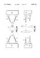
- FIG. 1is a system block diagram of a system made in accordance with the preferred embodiment of the invention.
- FIGS. 2A and 2Bare schematic block diagrams of the transmitter/receiver array and associated electronics in top plan and front elevational views, showing the staggered opposing pairs of microwave antenna elements.
- FIG. 3is a timing diagram illustrating the preferred timing by which the transmitter/receiver structures within the array of FIGS. 1, 2A and 2B are energized.
- FIG. 4shows a front elevation of the platform and rotary, arched antennae portal that form a part of the invention.
- FIG. 5shows a top plan view of the platform illustrated in FIG. 4.
- FIG. 6shows superimposed baseline and instant measurements of dielectric response of the invented system to human bodies standing on the platform.
- FIGS. 7A and 7Bshow two different computer display screens illustrating contraband detection and annunciation in accordance with the preferred embodiment of the invented system, with FIG. 7A showing a wire-frame figure with contraband in a first rotational orientation and with FIG. 7B showing the same figure in a second rotational orientation thereto.
- FIGS. 1 through 3it may be seen how the invented system preferably operates to detect and annunciate the presence of anomalous material, e.g. contraband, within the subject volume.
- anomalous materiale.g. contraband
- any anomalous reading representing a departure from a learned or defined baseline characteristicwill be flagged or annunciated, with identification of the region of the anomalous reading relative to the subject volume, but without identification of the type of contraband.
- a knife or plastic explosive or even a small quantity of cocainewithin, on or about a person may be discovered by searching the person in the identified region.
- baseline density measurementsmay be made of known target materials to profile and characterize their dielectric constant or other pertinent characteristics for positive contraband detection and annunciation. (This approach, which is deemed within the spirit and scope of the invention, is the complement of the preferred approach by which contraband type-undifferentiated readings outside physiological norms are identified as suspect.)
- lossless targetsmay be placed, for example, on a human subject, to assist in the establishment of such baselines as may be used for calibration of the invented system and for parameter storage in a memory device within the system's electronics for use by the discriminator described and illustrated herein.
- This last featureenables the invented system to distinguish, for example, between a metal implant within a person's body and a characteristically sharp blade and handle profile of a knife or the profile of another weapon such as a gun.
- the techniques described and illustrated in detail in my U.S. Pat. No. 4,975,968may be used of those skilled in the art to perform the needed calibrations and measurements for such positive contraband detection as is desired, wherein contraband is intended broadly to cover any material which might otherwise undesirably pass through the portal undetected.
- System 10preferably includes a generally circular platform 12 for a subject S or personnel to stand on while being screened for contraband, an arched portal 14 including one or more antennae arrays such as arrays 16, 18, with portal 14 being rotatable about a central axis A (see particularly FIG. 4) of platform 12, antennae arrays 16, 18 being operatively coupled with associated antennae drive and timing electronics (ANTENNAE DRIVE) indicated at 20 and a processor 22.
- processor 22includes a memory 24 at least a portion of which is non-volatile and a suitable display 26 which is preferably a high-resolution color monitor.
- system 10preferably also includes an ingress region indicated generally at 28, ingress region 28 preferably including a ramp 30 (refer briefly to FIGS. 4 and 5) and a profile station 32 operatively connected with processor 22 for determining the approximate height and weight of the screening subject.
- Profile station 32may profile the subject by any suitable means such as a proximity detector 34 for measuring the subject's height (the measurement technique being conventional, e.g. timing a reflected sonar, infrared (IR) or laser beam off the subject's head and determining height based on such timing) and a digital scales 36 for measuring the subject's weight (the measurement also being conventional).
- system 10also may include an egress region indicated generally at 38.
- system 10categorizes subjects such as subject S into one of thirty-two categories, i.e. four height classes, four weight classes and two sex classes. It is believed that such weight, height and sex criteria adequately establish a suitable body mass index (BMI) profile against which an individual subject S accurately may be compared to establish when the subject's measured dielectric profile exceeds the human population's norm thus indicating a high degree of probability that the subject is carrying contraband.
- BMIbody mass index
- Those skilled in the artswill appreciate that other baseline factors may be considered, or may be otherwise classified or may be classified into more or fewer physiological categories for comparison with a particular subject S undergoing screening, all within the spirit and scope of the invention.
- antennae arrays 16, 18preferably include plural, e.g. thirty-two, transmitter/receiver antennae pairs in a unique radially inwardly extending orientation from either side of arched portal 14 toward a test subject S.
- each antennae pairis made in accordance with the teachings of my above-referenced U.S. Pat. No. 4,949,094, as suggested by schematic FIGS. 2A and 2B.
- Electronics 20are indicated as being operatively and physically relatively closely coupled with each antenna within the plural pairs of antennae 16, 18, as will be understood by those of skill in the arts. From FIG.
- antennae arrays 16, 18generally oppose one another diametrically relative to axis A of circular platform 12.
- electronics 20are driven in timed response to drive signals produced by processor 22 to be in synchronism with rotation of platform 12 by any suitable rotary drive means or mechanism such as a servo motor 40 (FIG. 1) controlled also by processor 22.
- a servo motor 40FIG. 1
- relative rotation between platform 12 and portal 14may be achieved either by rotating platform 12 or portal 14, or both, all within the spirit and scope of the invention.
- alternate antennae within each allay 16, 18are axially, or radially, range-staggered as illustrated thereby to increase the sensitivity of system 10 to anomaly detection.
- This sensitivity increaseis achieved, as will be understood by those of skilled in the arts, by effectively transmitting and receiving two microwave energy fronts approximately 2" apart that confront the surface of the body of subject S.
- adjacent antennae within each of arrays 16, 18are vertically spaced approximately 8" apart such that the opposing allays define therebetween an effective vertical resolution of approximately 4".
- This effective enhancement of the vertical resolution of system 10is due to the complementary and opposing, radially staggered configuration of antennae arrays 16, 18 best illustrated in FIG. 2B.
- one complete rotation of portal 14is performed to screen each subject volume such as human subject S.
- Rotationmay be clockwise or counter-clockwise relative to rotational axis A (as seen by brief reference to FIGS. 7A and 7B).
- Rotation of portal 14 around subject Sis controlled by processor 22, and data correlation preferably is performed by processor 22 effectively to sum or average and otherwise normalize the rotation-produced dielectric profiles as between antennae array 16 and antennae allay 18 for comparison with baseline data representative of an at-large population.
- Counter-rotation between successive screeningseffectively unwinds the ⁇ umbilical ⁇ that extends over the curved arch or arched portal 14, the ⁇ umbilical ⁇ operatively, e.g. electrically, interconnecting antennae arrays 16, 18 on either side thereof and their associated drive and timing electronics 20.
- the transmitting/receiving antennae drive electronics timingis shown. It may be seen that for each transmitter/receiver antenna pair within arrays 16, 18 (timing diagrams for only four adjacent ones of which are shown in FIG. 3), the drive signal preferably has an approximately 3.2 millisecond (ms) period (in accordance with the preferred embodiment described and illustrated herein wherein antennae allays 16, 18 include thirty-two antennae in all) and an approximately 0.1 ms on-time for each vertical scan, thereby producing a relatively low duty cycle on each antenna in the antennae arrays.
- msmillisecond
- the angular sample period in which all thirty-two antennae in arrays 16, 18 are sequentially, preferably pair-wise energized and the dielectric response therein monitoredpreferably represents a 2° arc of the circle through which portal 14 rotates, which period corresponds generally with a human subject of nominal chest size to produce an approximately equilateral cube defining the 3-D spatial resolution of system 10.
- vertically adjacent antennae within each of the antennae arrays 16, 18are driven at once for approximately twice the duration of the drive timing pulses shown in FIG. 3.
- antennae 16 i and 16 jare driven by a stretched version of drive pulse T i
- antennae 16 j and 16 kare driven simultaneously by a stretched version of drive pulse T j
- antennae 16 k and 16 lare driven simultaneously by a stretched version of drive pulse T k
- antennae 16 l and 16 mare driven simultaneously by a stretched version of drive pulse T l
- a foreign object representing contraband on subject Swhich is tilted upwardly or downwardly relative to the radiation plane defined by a transmitter/receiver antennae pair (refer briefly to FIG. 2B) nevertheless is ⁇ seen ⁇ by the antennae array.
- 180 samplesare read by processor 22 per rotation of portal 14.
- processor 22per rotation of portal 14.
- any number of sampleswhether angular or vertical and any suitable timing and timebase resolution may be used in screening a subject for contraband.
- FIGS. 4 and 5show portal 14 and platform 12 in front elevational and cutaway top plan view, respectively.
- FIG. 4illustrates how arched portal 14 extends upwardly in left and right generally vertical columns 14a and 14b on either side of typically fully clothed subject S (indicated only in general outline), and preferably provides a handlebar 44 in an arched, central, overhead region 14c thereof to be grasped by the subject's two hands in order to extend the subject's arms upwardly clear of the subject's torso.
- proximity detector 34may be used by processor 22 to adjust the height of handlebar 44 above platform 12, thereby to ensure that the subject's arms are stretched sufficiently upwardly for relatively unobstructed illumination of the subject's body--including either side of the torso and the underarms--by antennae arrays 16, 18 but without discomfort to subject S.
- FIG. 4illustrates that, for safety and aesthetic reasons, preferably arched portal 14 is encased in any suitably durable and preferably lightweight material, e.g. molded polymer panels, that protect antennae arlays 16, 18 and electronics 20 from subject S and environmental forces such as airborne particulate and that protect subject S from incidental contact therewith.
- platform 12, portal 14 and ramp 30may be of any suitably durable, e.g. conventional, construction and material.
- FIG. 5shows a footprint pattern 42 on platform 12 that guides placement of the feet of subject S for optimal contraband screening. It will be appreciated that staggering the left and right feet by as little as a few inches during rotation of portal 14, a placement suggested by the left and right footprints of pattern 42 better illuminates the insides of the subject's legs and especially the thighs and crotch, thereby reducing the likelihood of undetected contraband hidden therearound. It will also be appreciated that providing footprints on platform 12 for subject S on which to position his or her feet ensures proper central positioning of the subject's body for maximum screening sensitivity and safety as arched portal 14 rotates around the subject.
- FIGS. 6A and 6Beach show superimposed dielectric baseline and response waveforms representative of microwave energy amplitude from antennae arrays 16, 18 incident on a clothed human subject standing on platform 12. All waveforms represent signal amplitude (ELEMENT VOLTS) along the ordinate and rotational angle along the abscissa.
- a trace labeled BASELINE in each of FIGS. 6A and 6Brepresents a human body characteristic amplitude waveform that is effectively learned by the computerized system over time. Preferably, such learning involves selective substitution of a peak amplitude in the waveform upon a higher measurement for a particular individual in a given time slot, although within the spirit and scope of the invention averaging or other methods may be used to establish and maintain the characteristic baseline waveform.
- Another trace labeled SCAN in each of FIGS. 6A and 6Brepresents actual measured amplitudes for a particular fictional individual having a contraband target underneath or within the individual's clothing. It may be seen at P in each of FIGS. 6A and 6B that there is a strong peak in measured amplitude representing an anomalous reading or perhaps indicating the presence of contraband on or near the individual at the height of the illustrated set of antennae. In FIG. 6A, this anomalous reading is at nearly 270° and in FIG. 6B this anomalous reading is at nearly 360° through a rotation of portal 14 the starting point of which is at the subject's right side.
- elevational and timebased location dataare derived from which antennae pair received the high-amplitude and long-duration signal response and when such occurred relative to rotation of platform 12, and may be selected for viewing by security personnel as by clicking on an icon or other push-button provided by processor 22 as part of a preferably graphic user interface (GUI) on display 26.
- GUIgraphic user interface
- nis the number of antennae pairs in one lateral allay, e.g. sixteen in accordance with the preferred embodiment of the invention.
- the computer interfacepermits any and all such waveforms to be displayed by scrolling, although of course it will be appreciated that those waveforms of interest are those in which a peak measured amplitude exceeds a defined threshold determined, preferably, at least in part by characteristic baseline measurements that are learned over time such that they represent the largest possible segment of the population.
- the waveform datais interpreted based upon the individual's height, i.e. the individual measurements are stretched or contracted vertically, effectively, to normalize their spread to the height-differentiated baseline spread.
- an individual height-influenced dielectric responseis comprehended by comparing it to a corresponding one of the stored, weight-categorized ⁇ models ⁇ or characteristic baseline responses. If such normalization were not performed by software in accordance with the preferred embodiment of the invention, a shorter individual's lower spine--which tends to reflect a relatively high response--might be mistaken for an anomalous response at the level of the individual's pelvis, which reflects a relatively low response. In this way, false-positives are largely avoided while sensitivity is maximized.
- vertical spatial resolutionis governed by n as well as by whether there are one or more such lateral arrays, with two arrays being preferably as described above to enhance the vertical spatial resolution.
- the time resolutionwill be understood to be determined by the angular rate of rotation of platform 12, which rate is practically limited by throughput requirements. Throughput of course is the inverse of the maximum allowable scan time per subject volume, which preferably does not exceed 3.5 seconds.
- FIGS. 7A and 7Bwhich correspond respectively with FIGS. 6A and 6B, detection of contraband on a subject is illustrated. It may be seen from FIGS. 7A and 7B that two human subjects each illustrated by a generic wire-frame human figure are shown in elevational views corresponding to the rotational angle at which the depicted anomaly is most ⁇ visible. ⁇ It will be appreciated that the novel use of generic wire-frame depictions of the human figure avoids the privacy-invasive, immodest suggestions of individual physical characteristics of human subjects that are typical of prior art screening systems.
- FIG. 7Aannunciates a detected anomaly preferably by a high-contrast visual graphic such as a distinctive rectilinear block (monochrome in the present drawings due to graphic art constraints but preferably by high-contrast color in accordance with the preferred embodiment of the invention) located at the subject's navel.
- FIG. 7Bsimilarly annunciates a detected anomaly located below the subject's lower right rib. Contrasting FIGS. 7A and 7B, it may be seen that in accordance with the preferred embodiment of the invention anomalous readings that may indicate the presence in the subject volume of contraband are generally centered left to right within a profile of a rotated, generic wire-frame human form. Either of the two illustrated screens selected from various viewing options by clicking on an icon or push-button would inform security personnel monitoring display 26 of the high likelihood of contraband being found in the indicated region within, on or around the subjects' persons, e.g. their attire.
- FIGS. 7A and 7Bmay be appreciated as illustrating other preferred features of the invented method and system 10 whereby the GUI provides security personnel a number of options. These may be seen to include a status window (EMERGENCY STOP), a push-button allay that permits manual scanning, waveform analysis, target location illustration (as is featured in FIGS. 7A and 7B), program exit, clockwise or counter-clockwise scanning, cancellation of a scan and manual moving. They also may be seen to include a number of selectable options including whether a male or female is scanned, whether a particular scan is added to the baseline database, whether moving clip levels are used and which type of scan is used (amplitude modulation (AM) v. phase modulation (PM) or arithmetic combinations thereof). Finally, the GUI preferably permits user selection and/or display of target trigger threshold, moving clip offset, upper and lower clip limits and subject height and weight.
- a status windowEMERGENCY STOP
- a push-button allaythat permits manual scanning
- waveform analysisas
- annunciation or other security measureare envisioned, e.g. an audible or silent alarm may ⁇ sound ⁇ , a surveillance camera may focus on the subject's further movements within the secured area, egress of subject S from platform 12 may be blocked, etc. All such remedial actions, however light- or heavy-handed, are contemplated and are within the spirit and scope of the invention.
- system 10constructed in accordance with the preferred embodiment described and illustrated herein--when adjusted not to exceed a false-positive indication level of only 5%--nevertheless achieves a true-positive detection accuracy of approximately 95% for metal targets, 90% for ceramics, 70% for polystyrene, 60% for synthetic iPod and 55% for synthetic drugs. It is noted that these last four target contraband categories very effectively detected in accordance with the invention heretofore have proven to be virtually undetectable with human subject screening and often have proven to be undetectable even with invasive X ray detection schemes.
- a conveyormay be included as a part of the invented system for moving personnel or material through such a portal as is described. In such a way, material or personnel that are otherwise immobile may be moved into relatively fixed position and screened for contraband within the rotational platform/portal construction, yet with all of the advantages of the invention in its preferred embodiment described herein.
- Such conveyormay be of any suitable design, as by effectively replacing the ingress and egress regions described and illustrated herein of the preferred embodiment, in accordance with the teachings of my above-referenced U.S. Pat. No. 4,975,968.
- the inventionnow may be understood in light of the invented system described above also to involve a dielectrometric method for screening a human subject, whether for contraband in the classic sense of something illicit or illegal or whether simply for a physiological abnormality.
- the invented stepspreferably include 1) providing an interrogation region within which the subject reposes, e.g. platform 12 and portal 14; 2) illuminating the subject within the interrogation region with microwave energy from an allay of plural transmitter/receiver antennae and monitoring the dielectric response therefrom, e.g.
- the methodfurther includes digitizing and storing the result of the monitoring in a memory.
- the irradiating-and-monitoring stepis performed by relatively rotating a generally planar perimetric antennae array, e.g. portal 14 including antennae arrays 16, 18, and a base, e.g. platform 12, supporting the subject in repose about an axis, e.g axis A which need not be vertical within the spirit and scope of the invention, generally aligned with the subject.
Landscapes
- Engineering & Computer Science (AREA)
- Physics & Mathematics (AREA)
- Life Sciences & Earth Sciences (AREA)
- Remote Sensing (AREA)
- Health & Medical Sciences (AREA)
- Radar, Positioning & Navigation (AREA)
- Electromagnetism (AREA)
- General Physics & Mathematics (AREA)
- Pathology (AREA)
- Biomedical Technology (AREA)
- Medical Informatics (AREA)
- Molecular Biology (AREA)
- Surgery (AREA)
- Animal Behavior & Ethology (AREA)
- General Health & Medical Sciences (AREA)
- Public Health (AREA)
- Veterinary Medicine (AREA)
- Heart & Thoracic Surgery (AREA)
- Biophysics (AREA)
- Environmental & Geological Engineering (AREA)
- Geology (AREA)
- General Life Sciences & Earth Sciences (AREA)
- Radiology & Medical Imaging (AREA)
- Geophysics (AREA)
- Nuclear Medicine, Radiotherapy & Molecular Imaging (AREA)
- Computer Networks & Wireless Communication (AREA)
- Radar Systems Or Details Thereof (AREA)
Abstract
Description
This application claims priority from U.S. Provisional Patent Application Ser. No. 60/035,668, filed Jan. 21, 1997 of Tex Yukl for PEOPLE PORTAL SECURITY SYSTEM, the disclosure of which is incorporated herein by reference.
The present invention relates generally to seculity systems and methods. More particularly, it concerns detection of contraband or definedly abnormal objects on persons or personnel and materials or material passing a security checkpoint.
This invention arises from improvements to apparatus which we previously developed, and from the adaptation of such apparatus to incorporate these improvements. The previously-developed apparatus are the subjects of: U.S. Pat. Nos. 4,234,844, issued Nov. 18, 1980 for "Electromagnetic Noncontacting Measuring Apparatus"; 4,318,108, issued Mar. 2, 1982 for "Bidirectionally Focusing Antenna"; 4,878,059 issued Oct. 31, 1989 for "Farfield/Nearfield Transmission/Reception Antenna"; 4,947,848, issued Aug. 14, 1990 for "Dielectric-Constant Change Monitoring"; 4,949,094, issued Aug. 14, 1990 for "Nearfield/Farfield Antenna With Parasitic Array"; and 4,975,968, issued Dec. 4, 1990 for "Timed Dielectrometry Surveillance Method and Apparatus". All of these patents are owned in common with the present application, and all are incorporated herein by reference.
There are two primary kinds of contraband detectors presently in use in existing security system. One is a whole body scanner through which people pass and which detects contraband material, such as weapons. The other is a luggage scanner through which material passes for the purpose of detecting contraband, such as bombs. Most such detectors bombard a target with X rays which are safe with material, but which progressively produce damage in the human body over time, and are known to be linked in a causal way to tissue damage that may lead to cancer. Other detectors look for a magnetic anomaly. All such detectors are useful for detecting metals only. These prior art detectors are singularly discriminate in terms of material density, and are indiscriminate in terms of volume. Thus, while they can detect weapons, they cannot detect plastiques or illicit drugs, and they might false-positively indicate that a ring of keys is a weapon. Time-consuming visual screening of captured X ray images, in the case of luggage, greatly slows down security-checkpoint processing of people and their luggage.
Imaging approaches to personnel screening tend to be invasive of a person's privacy and modesty. In other words, screening systems that image the person's body penetrate the person's clothes and highlight the person's physical attributes, effectively undressing the person. Thus, while human body image-reproduction systems, such as X ray systems, may be law-enforcement-friendly, they are traveler-unfriendly to the extent that they constitute an invasion of privacy. Also, and in the case of X ray detecting, such systems constitute a known health hazard.
Briefly, the invented system utilizes an array of microwave transmitter/receivers defining a pail of the perimeter of a portal through which personnel and/or material passes. Generally, the microwave transmitter/receivers are made in accordance with the teachings of the referenced patents. More specifically, they are preferably made in accordance with the priority provisional patent application referenced herein, which are characterized preferably by being spatially, e.g. radially or range-staggered in dual opposing arrays along spaced parallel, e.g. vertical, axes. Also preferably adjacent ones of the transmitter/receiver structures or microwave elements within each array are energized two or more at a time, or most preferably in pair-wise combination. The elements within the array are energized, for illumination of the targeted standing personnel or stationary material, by scanning therearound within an arched portal as in an airport or other secure site, by operatively connected electronics. The interrogated region or volume, whether a standing person or fixed material or the object of interest therein, will be referred to herein as the subject volume, or more simply, the subject.
Preferably, the electronics also monitor and preferably record, e.g. in a memory as a representation thereof in digital form, data characterizing the response of the subject volume to such illumination. Successive time-slice representations of the dielectric constant (propagation) and loss tangent (dissipation) of the region under interrogation of may be derived and may be optionally displayed, as on a display monitor operatively associated with the electronics. A 2-D representation of a 3-D time slice of the subject volume also may be displayed in the form of a modesty-friendly wire-frame image.
Preferably, a discriminator that may take the form of a suitably programmed digital computer or processor that compares the derived dielectric constants with characteristic or baseline dielectric constant ranges stored in a memory determines whether contraband is present in the subject volume and may notify security personnel engaged in monitoring the secure site. Contraband, as used herein, refers to any material within the subject volume constituents of which are determined to be outside predetermined characteristic norms. For a human subject, such norms are physiological norms determined by understanding the normal fluid, tissue and bone constituents of approximately the first two-and-one-half wavelengths (2.5λ) of penetration by microwave energy beneath the human subject's skin. For a material subject, such norms are those determined by assumptions regarding the normal constituents of the material within a volume penetrated by the microwave energy. Once the `normal` contents of the subject volume are determined, then anything more than marginally outside such norms may be defined as contraband, within the broad definition of contraband used herein.
The invention in accordance with its preferred embodiment features a platform with an ingress and egress ramp wherein the platform represents an arched portal in which a person stands immobile while contraband screening takes place. The person's height and weight are measured on the way up the ingress ramp, and the person stands with arms reaching upwardly to grasp a handlebar pre-positioned to the subject's height. An array of antennae mounted within an arched structure is rotated once around the person to collect baseline and other information. Radially inwardly directed pairs of coupled transmitting and receiving antennas arrayed vertically on either side of the platform preferably are constructed in accordance with my U.S. Pat. Nos. 4,878,059 and 4,949,094 respectively entitled "Farfield/Nearfield Transmission/Reception Antenna" and "Nearfield/Farfield Antenna With Parasitic Array".
Antennae driver/receiver electronics are operatively coupled with the antennae arrays to energize the antennae and to measure the dielectric response of the person's body to harmless microwave stimuli preferably in the 5.5 gigaHertz (GHz) range, requiring an antenna having a gain of approximately 14 dbi, an efficiency of approximately 80% and a relatively flat, narrow band-pass, e.g. preferably between 5.0 and 6.0 GHz and more preferably between 5.3 and 5.7 GHz.
A small, high-efficiency antenna is most desirable for use in the present invention in order to minimize the penetration depth-to-range ratio and thus to maximize resulting contrast or signal-to-noise ratio (SNR). In other words, it is desirable to maintain a minimum range between antenna and subject thereby to reduce the distance through the air-as-dielectric space therebetween and to keep each antenna three-dimensionally compact. For these operational reasons, and also in the interest of lightweight and relatively inexpensive system components, antennae with parasitic arrays which are constructed in accordance with above-referenced U.S. Pat. No. 4,949,094 have been found to be most desirable. Those of skill in the art will appreciate, however, that the use of suitable alternatives is contemplated, and is within the spirit and scope of the invention.
An individual's response is compared to a databased baseline response representative of a person of such determined height and weight (or so-called body mass index (BMI)), and peak amplitude and duration excesses over the characteristic baseline are determined to be contraband. In the illustrated application and in accordance with the preferred embodiment of the invention, computer-based imaging system operatively coupled with the electronics uses a generic, wire-frame human body depiction on which anomalous readings that may be indicative of contraband on a human subject standing in the portal is detected, with the contraband being annunciated visually and suitably located on the wire-frame depiction for further manual and/or portable dielectrometer-based searching as is indicated.
These and additional objects and advantages of the present invention will be more readily understood after consideration of the drawings and the detailed description of the preferred embodiment which follows.
FIG. 1 is a system block diagram of a system made in accordance with the preferred embodiment of the invention.
FIGS. 2A and 2B are schematic block diagrams of the transmitter/receiver array and associated electronics in top plan and front elevational views, showing the staggered opposing pairs of microwave antenna elements.
FIG. 3 is a timing diagram illustrating the preferred timing by which the transmitter/receiver structures within the array of FIGS. 1, 2A and 2B are energized.
FIG. 4 shows a front elevation of the platform and rotary, arched antennae portal that form a part of the invention.
FIG. 5 shows a top plan view of the platform illustrated in FIG. 4.
FIG. 6 shows superimposed baseline and instant measurements of dielectric response of the invented system to human bodies standing on the platform.
FIGS. 7A and 7B show two different computer display screens illustrating contraband detection and annunciation in accordance with the preferred embodiment of the invented system, with FIG. 7A showing a wire-frame figure with contraband in a first rotational orientation and with FIG. 7B showing the same figure in a second rotational orientation thereto.
Referring collectively to FIGS. 1 through 3, it may be seen how the invented system preferably operates to detect and annunciate the presence of anomalous material, e.g. contraband, within the subject volume. It will be understood that any anomalous reading representing a departure from a learned or defined baseline characteristic will be flagged or annunciated, with identification of the region of the anomalous reading relative to the subject volume, but without identification of the type of contraband. Nevertheless, because most weapons and illicit drugs will produce anomalous readings, a knife or plastic explosive or even a small quantity of cocaine, within, on or about a person may be discovered by searching the person in the identified region. Those of skill in the arts will appreciate that FIGS. 1 through 3 are illustrative only of the invented system and are not intended to limit the scope of the present patent in any way.
Those of skill in the arts will appreciate that baseline density measurements may be made of known target materials to profile and characterize their dielectric constant or other pertinent characteristics for positive contraband detection and annunciation. (This approach, which is deemed within the spirit and scope of the invention, is the complement of the preferred approach by which contraband type-undifferentiated readings outside physiological norms are identified as suspect.) Those of skill also will appreciate that lossless targets may be placed, for example, on a human subject, to assist in the establishment of such baselines as may be used for calibration of the invented system and for parameter storage in a memory device within the system's electronics for use by the discriminator described and illustrated herein.
Those of skill in the ails also will appreciate that the use of two or more out-of-phase, elliptically polarized, preferably microwave, transmitters and an interposed receiver ensures constant subject or target illumination that tends to be otherwise obscured by motion artifacts (i.e. the second opposing array is likely to `see` that to which the first array is `blind`). Finally, those of skill in the ails will appreciate that cancellation of phase modulation and use of amplitude modulation may facilitate two- or three-dimensional profiling and modeling for contraband detection and annunciation purposes, as such enhance object and edge surface detection. This last feature enables the invented system to distinguish, for example, between a metal implant within a person's body and a characteristically sharp blade and handle profile of a knife or the profile of another weapon such as a gun. The techniques described and illustrated in detail in my U.S. Pat. No. 4,975,968 may be used of those skilled in the art to perform the needed calibrations and measurements for such positive contraband detection as is desired, wherein contraband is intended broadly to cover any material which might otherwise undesirably pass through the portal undetected.
Turning now to FIG. 1, a system block diagram of the invented system is indicated at 10.System 10 preferably includes a generallycircular platform 12 for a subject S or personnel to stand on while being screened for contraband, anarched portal 14 including one or more antennae arrays such asarrays portal 14 being rotatable about a central axis A (see particularly FIG. 4) ofplatform 12,antennae arrays processor 22. Preferably,processor 22 includes amemory 24 at least a portion of which is non-volatile and asuitable display 26 which is preferably a high-resolution color monitor.
In accordance with the preferred embodiment of the invention,system 10 preferably also includes an ingress region indicated generally at 28,ingress region 28 preferably including a ramp 30 (refer briefly to FIGS. 4 and 5) and aprofile station 32 operatively connected withprocessor 22 for determining the approximate height and weight of the screening subject.Profile station 32 may profile the subject by any suitable means such as a proximity detector 34 for measuring the subject's height (the measurement technique being conventional, e.g. timing a reflected sonar, infrared (IR) or laser beam off the subject's head and determining height based on such timing) and adigital scales 36 for measuring the subject's weight (the measurement also being conventional). Those of skill in the arts will appreciate that an individual subject's height and weight are needed to account for variations thereof from expected human body characteristics or norms stored preferably in the non-volatile portion ofmemory 24. Optionally,system 10 also may include an egress region indicated generally at 38.
In accordance with the preferred embodiment of the invention,system 10 categorizes subjects such as subject S into one of thirty-two categories, i.e. four height classes, four weight classes and two sex classes. It is believed that such weight, height and sex criteria adequately establish a suitable body mass index (BMI) profile against which an individual subject S accurately may be compared to establish when the subject's measured dielectric profile exceeds the human population's norm thus indicating a high degree of probability that the subject is carrying contraband. Those skilled in the arts will appreciate that other baseline factors may be considered, or may be otherwise classified or may be classified into more or fewer physiological categories for comparison with a particular subject S undergoing screening, all within the spirit and scope of the invention.
Turning next to FIGS. 2A and 2B, it may be seen thatantennae arrays Electronics 20 are indicated as being operatively and physically relatively closely coupled with each antenna within the plural pairs ofantennae arrays antennae arrays array system 10. It will be appreciated that an anomaly representing a foreign object on subject S that might be obscured from the `view` ofantennae array 16, nevertheless is more likely to be `seen` by complementarily range staggeredantennae array 18, as will now be described.
It will be appreciated thatantennae arrays circular platform 12. Moreover, it may be seen from FIG. 2 thatelectronics 20 are driven in timed response to drive signals produced byprocessor 22 to be in synchronism with rotation ofplatform 12 by any suitable rotary drive means or mechanism such as a servo motor 40 (FIG. 1) controlled also byprocessor 22. Those skilled in the art will appreciate that relative rotation betweenplatform 12 and portal 14 may be achieved either by rotatingplatform 12 or portal 14, or both, all within the spirit and scope of the invention.
Preferably, alternate antennae within each allay 16, 18 are axially, or radially, range-staggered as illustrated thereby to increase the sensitivity ofsystem 10 to anomaly detection. This sensitivity increase is achieved, as will be understood by those of skilled in the arts, by effectively transmitting and receiving two microwave energy fronts approximately 2" apart that confront the surface of the body of subject S. Preferably, adjacent antennae within each ofarrays system 10 is due to the complementary and opposing, radially staggered configuration ofantennae arrays
In accordance with the preferred method of the invention, one complete rotation ofportal 14 is performed to screen each subject volume such as human subject S. Rotation may be clockwise or counter-clockwise relative to rotational axis A (as seen by brief reference to FIGS. 7A and 7B). Rotation ofportal 14 around subject S is controlled byprocessor 22, and data correlation preferably is performed byprocessor 22 effectively to sum or average and otherwise normalize the rotation-produced dielectric profiles as betweenantennae array 16 and antennae allay 18 for comparison with baseline data representative of an at-large population. Counter-rotation between successive screenings effectively unwinds the `umbilical` that extends over the curved arch orarched portal 14, the `umbilical` operatively, e.g. electrically, interconnectingantennae arrays electronics 20.
Referring very briefly now to FIG. 3, the transmitting/receiving antennae drive electronics timing is shown. It may be seen that for each transmitter/receiver antenna pair withinarrays 16, 18 (timing diagrams for only four adjacent ones of which are shown in FIG. 3), the drive signal preferably has an approximately 3.2 millisecond (ms) period (in accordance with the preferred embodiment described and illustrated herein wherein antennae allays 16, 18 include thirty-two antennae in all) and an approximately 0.1 ms on-time for each vertical scan, thereby producing a relatively low duty cycle on each antenna in the antennae arrays. The angular sample period in which all thirty-two antennae inarrays portal 14 rotates, which period corresponds generally with a human subject of nominal chest size to produce an approximately equilateral cube defining the 3-D spatial resolution ofsystem 10.
Importantly, and in order to optimally illuminate a subject within the interrogation region defined byportal 14 and to detect anomalous readings therefrom, vertically adjacent antennae within each of theantennae arrays adjacent antennae array 16 and continuing on in the same direction through all sixteen antennae withinarray 18. In this way, a foreign object representing contraband on subject S which is tilted upwardly or downwardly relative to the radiation plane defined by a transmitter/receiver antennae pair (refer briefly to FIG. 2B) nevertheless is `seen` by the antennae array.
In accordance with the preferred embodiment of the invention, 180 samples are read byprocessor 22 per rotation ofportal 14. Those of skill in the arts will appreciate that, within the spirit and scope of the invention, any number of samples, whether angular or vertical and any suitable timing and timebase resolution may be used in screening a subject for contraband.
FIGS. 4 and 5show portal 14 andplatform 12 in front elevational and cutaway top plan view, respectively. FIG. 4 illustrates howarched portal 14 extends upwardly in left and right generally vertical columns 14a and 14b on either side of typically fully clothed subject S (indicated only in general outline), and preferably provides ahandlebar 44 in an arched, central, overhead region 14c thereof to be grasped by the subject's two hands in order to extend the subject's arms upwardly clear of the subject's torso. It will be appreciated that the height measurement described above as being made by proximity detector 34 may be used byprocessor 22 to adjust the height ofhandlebar 44 aboveplatform 12, thereby to ensure that the subject's arms are stretched sufficiently upwardly for relatively unobstructed illumination of the subject's body--including either side of the torso and the underarms--byantennae arrays
FIG. 4 illustrates that, for safety and aesthetic reasons, preferably arched portal 14 is encased in any suitably durable and preferably lightweight material, e.g. molded polymer panels, that protectantennae arlays electronics 20 from subject S and environmental forces such as airborne particulate and that protect subject S from incidental contact therewith. Those of skill in the arts will appreciate thatplatform 12,portal 14 andramp 30 may be of any suitably durable, e.g. conventional, construction and material.
FIG. 5 shows afootprint pattern 42 onplatform 12 that guides placement of the feet of subject S for optimal contraband screening. It will be appreciated that staggering the left and right feet by as little as a few inches during rotation ofportal 14, a placement suggested by the left and right footprints ofpattern 42 better illuminates the insides of the subject's legs and especially the thighs and crotch, thereby reducing the likelihood of undetected contraband hidden therearound. It will also be appreciated that providing footprints onplatform 12 for subject S on which to position his or her feet ensures proper central positioning of the subject's body for maximum screening sensitivity and safety asarched portal 14 rotates around the subject.
FIGS. 6A and 6B each show superimposed dielectric baseline and response waveforms representative of microwave energy amplitude fromantennae arrays platform 12. All waveforms represent signal amplitude (ELEMENT VOLTS) along the ordinate and rotational angle along the abscissa. A trace labeled BASELINE in each of FIGS. 6A and 6B represents a human body characteristic amplitude waveform that is effectively learned by the computerized system over time. Preferably, such learning involves selective substitution of a peak amplitude in the waveform upon a higher measurement for a particular individual in a given time slot, although within the spirit and scope of the invention averaging or other methods may be used to establish and maintain the characteristic baseline waveform.
Another trace labeled SCAN in each of FIGS. 6A and 6B represents actual measured amplitudes for a particular fictional individual having a contraband target underneath or within the individual's clothing. It may be seen at P in each of FIGS. 6A and 6B that there is a strong peak in measured amplitude representing an anomalous reading or perhaps indicating the presence of contraband on or near the individual at the height of the illustrated set of antennae. In FIG. 6A, this anomalous reading is at nearly 270° and in FIG. 6B this anomalous reading is at nearly 360° through a rotation of portal 14 the starting point of which is at the subject's right side. These elevational and timebased location data are derived from which antennae pair received the high-amplitude and long-duration signal response and when such occurred relative to rotation ofplatform 12, and may be selected for viewing by security personnel as by clicking on an icon or other push-button provided byprocessor 22 as part of a preferably graphic user interface (GUI) ondisplay 26. Those of skill in the art will appreciate that such peaks P flagged by inventedsystem 10 may be evaluated by determined threshold criteria such as amplitude (labeled H for height in FIG. 6A) and duration (labeled W for width in FIG. 6A), such that only nominal excursions are not flagged while excursions of significance are flagged as indications of anomalous readings.
It will be understood that typically there are stored in memory associated with processor 22 n such waveforms for each tested subject, where n is the number of antennae pairs in one lateral allay, e.g. sixteen in accordance with the preferred embodiment of the invention. The computer interface permits any and all such waveforms to be displayed by scrolling, although of course it will be appreciated that those waveforms of interest are those in which a peak measured amplitude exceeds a defined threshold determined, preferably, at least in part by characteristic baseline measurements that are learned over time such that they represent the largest possible segment of the population.
Finally, it will be appreciated that the waveform data is interpreted based upon the individual's height, i.e. the individual measurements are stretched or contracted vertically, effectively, to normalize their spread to the height-differentiated baseline spread. In this way, an individual height-influenced dielectric response is comprehended by comparing it to a corresponding one of the stored, weight-categorized `models` or characteristic baseline responses. If such normalization were not performed by software in accordance with the preferred embodiment of the invention, a shorter individual's lower spine--which tends to reflect a relatively high response--might be mistaken for an anomalous response at the level of the individual's pelvis, which reflects a relatively low response. In this way, false-positives are largely avoided while sensitivity is maximized.
It also will be understood that vertical spatial resolution is governed by n as well as by whether there are one or more such lateral arrays, with two arrays being preferably as described above to enhance the vertical spatial resolution. The time resolution will be understood to be determined by the angular rate of rotation ofplatform 12, which rate is practically limited by throughput requirements. Throughput of course is the inverse of the maximum allowable scan time per subject volume, which preferably does not exceed 3.5 seconds.
Turning now to FIGS. 7A and 7B, which correspond respectively with FIGS. 6A and 6B, detection of contraband on a subject is illustrated. It may be seen from FIGS. 7A and 7B that two human subjects each illustrated by a generic wire-frame human figure are shown in elevational views corresponding to the rotational angle at which the depicted anomaly is most `visible.` It will be appreciated that the novel use of generic wire-frame depictions of the human figure avoids the privacy-invasive, immodest suggestions of individual physical characteristics of human subjects that are typical of prior art screening systems.
FIG. 7A annunciates a detected anomaly preferably by a high-contrast visual graphic such as a distinctive rectilinear block (monochrome in the present drawings due to graphic art constraints but preferably by high-contrast color in accordance with the preferred embodiment of the invention) located at the subject's navel. FIG. 7B similarly annunciates a detected anomaly located below the subject's lower right rib. Contrasting FIGS. 7A and 7B, it may be seen that in accordance with the preferred embodiment of the invention anomalous readings that may indicate the presence in the subject volume of contraband are generally centered left to right within a profile of a rotated, generic wire-frame human form. Either of the two illustrated screens selected from various viewing options by clicking on an icon or push-button would inform securitypersonnel monitoring display 26 of the high likelihood of contraband being found in the indicated region within, on or around the subjects' persons, e.g. their attire.
FIGS. 7A and 7B may be appreciated as illustrating other preferred features of the invented method andsystem 10 whereby the GUI provides security personnel a number of options. These may be seen to include a status window (EMERGENCY STOP), a push-button allay that permits manual scanning, waveform analysis, target location illustration (as is featured in FIGS. 7A and 7B), program exit, clockwise or counter-clockwise scanning, cancellation of a scan and manual moving. They also may be seen to include a number of selectable options including whether a male or female is scanned, whether a particular scan is added to the baseline database, whether moving clip levels are used and which type of scan is used (amplitude modulation (AM) v. phase modulation (PM) or arithmetic combinations thereof). Finally, the GUI preferably permits user selection and/or display of target trigger threshold, moving clip offset, upper and lower clip limits and subject height and weight.
Those of skill in the art will appreciate that, while a graphic display indicating the actual location of the anomalous reading relative to the subject is desirable, nevertheless alternative forms of annunciation or other security measure are envisioned, e.g. an audible or silent alarm may `sound`, a surveillance camera may focus on the subject's further movements within the secured area, egress of subject S fromplatform 12 may be blocked, etc. All such remedial actions, however light- or heavy-handed, are contemplated and are within the spirit and scope of the invention.
It has been demonstrated by the use of the invention made in accordance with its preferred embodiment that unprecedented versatility and accuracy may be achieved in screening a subject for contraband, yet in keeping with safety and other regulatory, sensitivity, privacy and throughput goals. For example,system 10 constructed in accordance with the preferred embodiment described and illustrated herein--when adjusted not to exceed a false-positive indication level of only 5%--nevertheless achieves a true-positive detection accuracy of approximately 95% for metal targets, 90% for ceramics, 70% for polystyrene, 60% for synthetic plastique and 55% for synthetic drugs. It is noted that these last four target contraband categories very effectively detected in accordance with the invention heretofore have proven to be virtually undetectable with human subject screening and often have proven to be undetectable even with invasive X ray detection schemes.
Importantly, no combination of such metal, ceramic, polystyrene, plastique or drug targets is predictably undetected despite the less-than-perfect sensitivity of inventedsystem 10. Instead, any likelihood of missing the above-listed and other non-physiological objects during a physiological screen of a human subject is so low and unpredictable that it cannot be counted on. In other words, there is believed to be no combination of the above-described contraband contents of subject volume that one may reasonably expect to be screened by inventedsystem 10 without discovery. Accordingly, althoughsystem 10's extremely high sensitivity is not infinite, nevertheless it is sufficiently high to deter even the most careful or ingenious attempt to elude its detection capability.
Those of skill in the art will appreciate that a conveyor may be included as a part of the invented system for moving personnel or material through such a portal as is described. In such a way, material or personnel that are otherwise immobile may be moved into relatively fixed position and screened for contraband within the rotational platform/portal construction, yet with all of the advantages of the invention in its preferred embodiment described herein. Such conveyor may be of any suitable design, as by effectively replacing the ingress and egress regions described and illustrated herein of the preferred embodiment, in accordance with the teachings of my above-referenced U.S. Pat. No. 4,975,968.
The invention now may be understood in light of the invented system described above also to involve a dielectrometric method for screening a human subject, whether for contraband in the classic sense of something illicit or illegal or whether simply for a physiological abnormality. The invented steps preferably include 1) providing an interrogation region within which the subject reposes,e.g. platform 12 and portal 14; 2) illuminating the subject within the interrogation region with microwave energy from an allay of plural transmitter/receiver antennae and monitoring the dielectric response therefrom, e.g. via the use ofantennae arrays processor 22 andmemory 24 being used for digital data storage preferably in a multi-dimensional array. Thus, it may be seen that the method does not require that the human subject be standing, only that the subject preferably be in relatively calm repose so that motion artifacts are avoided. Those of skill in the art will appreciate that myriad physiological screening criteria may be used in such a method.
Preferably, after the irradiating and before the comparing steps, the method further includes digitizing and storing the result of the monitoring in a memory. Also preferably, the irradiating-and-monitoring step is performed by relatively rotating a generally planar perimetric antennae array, e.g. portal 14 includingantennae arrays e.g. platform 12, supporting the subject in repose about an axis, e.g axis A which need not be vertical within the spirit and scope of the invention, generally aligned with the subject.
Accordingly, while the present invention has been shown and described with reference to the foregoing preferred system, it will be apparent to those skilled in the art that other changes in form and detail may be made therein without departing from the spirit and scope of the invention as defined in the appended claims.
Claims (20)
1. A security system for contraband detection comprising:
a portal defining an interrogation region therewithin into which region a screening target may be introduced;
a transmitter/receiver array mounted in a defined at least partial perimeter around said region for illuminating the target by a first microwave beam and for monitoring the dielectric response to said first microwave beam to produce a dielectric response signal representative of the dielectric response of the target to microwave illumination; and
electronics operatively connected with said transmitter/receiver array for energizing said array in accordance with defined microwave energy amplitude and timing characteristics and for monitoring said dielectric response signal, said electronics including a discriminator for comparing said dielectric response signal with a defined characteristic response signal, said electronics producing an indication of a difference therebetween meeting predefined criteria.
2. The system of claim 1, wherein said transmitter/receiver array includes plural transmitter/receiver structures arrayed in an opposing, staggered spatial relationship with one another that defines at least a part of said portal.
3. The system of claim 2, wherein ones of said plural transmitter/receiver structures are energized by said electronics in pair-wise combination for concurrent illumination by said ones of the target for a first defined period of time and wherein other ones of said plural transmitter/receiver structures are energized by said electronics also in pair-wise combination for concurrent illumination by said other ones of the target for a second defined period of time that is substantially different from said first defined period of time.
4. The system of claim 2, wherein said transmitter/receiver array includes an elliptically polarized microwave energy source.
5. The system of claim 1 which further comprises an annunciator operatively connected with said discriminator for notifying security personnel of such indication.
6. The system of claim 5, wherein said annunicator includes a display monitor for indicating within the target the physical location therein corresponding with the indicated difference.
7. The system of claim 6 in which the target is a human subject, wherein said display monitor includes a depiction of a generic human form and wherein the physical location is indicated by a high-contrast graphic feature superimposed on said depiction.
8. The system of claim 1 which further includes a platform beneath said portal for supporting the target within said interrogation region, wherein said portal and said platform are rotatable relative to one another for illumination of said interrogation region from substantially all sides by said transmitter/receiver array.
9. The system of claim 1, wherein said electronics include a digitizer for the monitoring, a digital memory for buffering and a digital processor for the comparing and wherein the dielectric response of the target to the illumination is derived by said electronics, wherein said digital memory includes stored contraband dielectric constant parameters used by said discriminator for comparison thereof with the derived dielectric constant of the target.
10. The system of claim 9 which further comprises an annunciator for indicating the derived dielectric constant of the target, wherein said processor produces an indication of said derived dielectric constant for notifying by said annunciator.
11. A security system for contraband detection comprising:
a platform on which personnel may stand;
a rotary drive mechanism adjacent said platform;
a portal adjacent said platform and extending upwardly therefrom, said portal and said platform being rotatable by said rotary drive mechanism relative to one another, said portal including generally vertical upward extents each having antennae arrays therein operative to illuminate such personnel standing on said platform with microwave energy and to measure the dielectric response of such personnel to said illumination to produce a response signal representative of such dielectric response during relative rotation of said portal and said platform; and
a processor for time-correlating said response signal with the relative rotation of said portal and said platform to produce spatio-temporal data indicative of the dielectric response of such personnel to such illumination, said processor further for comparing such data to previously stored baseline data and for annunciating any differences therebetween which meet predefined criteria indicating the presence of contraband adjacent such personnel.
12. The system of claim 11 which further comprises a display monitor for illustrating the physical location relative such personnel of the presence of contraband.
13. The system of claim 12 which further comprises a personnel body height measurement subsystem operatively connected with said processor for compensating for such personnel's height during such comparing.
14. The system of claim 13 which further comprises a personnel body weight measurement subsystem operatively connected with said processor for compensating for such personnel's weight during such comparing.
15. The system of claim 11, wherein said antennae arrays are operative to illuminate such personnel with microwave energy in a frequency range between approximately 5 and 6 gigaHertz.
16. The system of claim 15, wherein said antennae arrays are operative to illuminate such personnel with microwave energy in a frequency range between approximately 5.3 and 5.7 gigaHertz.
17. The system of claim 16, wherein said antennae arrays are operative to illuminate such personnel with microwave energy at a frequency of approximately 5.5 gigaHertz.
18. A dielectrometric method for screening a human subject comprising:
providing an interrogation region within which the subject reposes;
illuminating the subject within the interrogation region with microwave energy from an array of plural transmitter/receiver antennae and monitoring the dielectric response therefrom;
comparing the dielectric response with baseline physiological response data stored in memory to produce data representative of any difference therebetween; and
evaluating such data by use of defined screening criteria.
19. The method of claim 18 which further comprises, after said illuminating-and-monitoring and before said comparing steps, digitizing and storing such result of said monitoring in a memory.
20. The method of claim 18, wherein said illuminating-and-monitoring step is performed by relatively rotating a generally planar perimetric antennae array and a base supporting the subject in repose about an axis generally aligned with the subject.
Priority Applications (2)
| Application Number | Priority Date | Filing Date | Title |
|---|---|---|---|
| US09/010,275US6057761A (en) | 1997-01-21 | 1998-01-21 | Security system and method |
| IL12817199AIL128171A0 (en) | 1998-01-21 | 1999-01-21 | Security system |
Applications Claiming Priority (2)
| Application Number | Priority Date | Filing Date | Title |
|---|---|---|---|
| US3655897P | 1997-01-21 | 1997-01-21 | |
| US09/010,275US6057761A (en) | 1997-01-21 | 1998-01-21 | Security system and method |
Publications (1)
| Publication Number | Publication Date |
|---|---|
| US6057761Atrue US6057761A (en) | 2000-05-02 |
Family
ID=26680988
Family Applications (1)
| Application Number | Title | Priority Date | Filing Date |
|---|---|---|---|
| US09/010,275Expired - LifetimeUS6057761A (en) | 1997-01-21 | 1998-01-21 | Security system and method |
Country Status (1)
| Country | Link |
|---|---|
| US (1) | US6057761A (en) |
Cited By (119)
| Publication number | Priority date | Publication date | Assignee | Title |
|---|---|---|---|---|
| US6472984B1 (en)* | 1998-10-20 | 2002-10-29 | Georal International Ltd. | Security entrance system |
| US6480141B1 (en) | 2001-03-13 | 2002-11-12 | Sandia Corporation | Detection of contraband using microwave radiation |
| US20040012398A1 (en)* | 1999-12-30 | 2004-01-22 | Bailey Kenneth S. | Human body: scanning, typing and profiling system |
| US6724304B2 (en)* | 1998-10-20 | 2004-04-20 | Georal International Ltd. | Security entrance system |
| US20040080315A1 (en)* | 2002-10-25 | 2004-04-29 | Beevor Simon Peter | Object detection portal with video display overlay |
| US20040090359A1 (en)* | 2001-03-16 | 2004-05-13 | Mcmakin Douglas L. | Detecting concealed objects at a checkpoint |
| US20040104268A1 (en)* | 2002-07-30 | 2004-06-03 | Bailey Kenneth Stephen | Plug in credit card reader module for wireless cellular phone verifications |
| US20040140924A1 (en)* | 2001-03-16 | 2004-07-22 | Keller Paul E. | Detection of a concealed object |
| US6784854B1 (en) | 2002-03-25 | 2004-08-31 | Spatial Dynamics, Ltd. | Dielectric detection through conductive metal |
| US20040189469A1 (en)* | 2003-03-25 | 2004-09-30 | Accenture Global Services Gmbh | Security checkpoint |
| US20040263379A1 (en)* | 2003-06-26 | 2004-12-30 | Keller Paul E. | Concealed object detection |
| US20050074086A1 (en)* | 2003-10-07 | 2005-04-07 | Accenture Global Services Gmbh | Mobile security unit |
| US20050083245A1 (en)* | 2003-10-15 | 2005-04-21 | Spatial Dynamics, Ltd. | Integrated microwave transceiver tile structure |
| US20050122257A1 (en)* | 2003-12-05 | 2005-06-09 | Rowe Richard L. | Millimeter-wave active imaging system with fixed array |
| US20050122249A1 (en)* | 2003-12-05 | 2005-06-09 | Grudkowski Thomas W. | Millimeter-wave active imaging system |
| US20050122258A1 (en)* | 2003-12-05 | 2005-06-09 | Blasing Raymond R. | Millimeter-wave active imaging system with modular array |
| US6927691B2 (en) | 2002-03-25 | 2005-08-09 | Spatial Dynamics, Ltd. | Dielectric personnel scanning |
| WO2005078462A1 (en)* | 2004-01-16 | 2005-08-25 | Kenneth Stephen Bailey | Human body: scanning, typing and profiling system |
| US20050230604A1 (en)* | 2004-04-14 | 2005-10-20 | Rowe Richard L | Multi-sensor surveillance portal |
| US20050231416A1 (en)* | 2004-04-14 | 2005-10-20 | Rowe Richard L | Relational millimeter-wave interrogating |
| US20050231421A1 (en)* | 2004-04-14 | 2005-10-20 | Michael Fleisher | Enhanced surveilled subject imaging |
| US20050232487A1 (en)* | 2004-04-14 | 2005-10-20 | Safeview, Inc. | Active subject privacy imaging |
| US20050231417A1 (en)* | 2004-04-14 | 2005-10-20 | Michael Fleisher | Surveilled subject privacy imaging |
| US20050231415A1 (en)* | 2004-04-14 | 2005-10-20 | Michael Fleisher | Surveilled subject imaging with object identification |
| US20050232459A1 (en)* | 2004-04-14 | 2005-10-20 | Rowe Richard L | Multi-source surveillance portal |
| US6965340B1 (en)* | 2004-11-24 | 2005-11-15 | Agilent Technologies, Inc. | System and method for security inspection using microwave imaging |
| US6967612B1 (en)* | 2004-10-22 | 2005-11-22 | Gorman John D | System and method for standoff detection of human carried explosives |
| US20050264303A1 (en)* | 2004-02-12 | 2005-12-01 | Bailey Kenneth S | Radiation monitoring of body part sizing and use of such sizing for person monitoring |
| US6972714B1 (en) | 2004-06-08 | 2005-12-06 | Agilent Technologies, Inc. | Optically-augmented microwave imaging system and method |
| US20050280533A1 (en)* | 2004-06-16 | 2005-12-22 | Lixin Yao Yao | Apparatus for Automatic Height Measurement |
| US20060066469A1 (en)* | 2004-09-24 | 2006-03-30 | Foote Harlan P | Three-dimensional surface/contour processing based on electromagnetic radiation interrogation |
| WO2005050160A3 (en)* | 2003-10-30 | 2006-04-06 | Battelle Memorial Institute | Detection of a concealed object |
| US20060104480A1 (en)* | 2004-11-12 | 2006-05-18 | Safeview, Inc. | Active subject imaging with body identification |
| US20060104489A1 (en)* | 2004-08-23 | 2006-05-18 | Bailey Kenneth S | Minutia detection from measurement of a human skull and identifying and profiling individuals from the human skull detection |
| US20060109174A1 (en)* | 2004-11-24 | 2006-05-25 | Izhak Baharav | System and method for microwave imaging using programmable transmission array |
| US20060164287A1 (en)* | 2005-01-21 | 2006-07-27 | Safeview, Inc. | Depth-based surveillance image reconstruction |
| US20060164286A1 (en)* | 2005-01-21 | 2006-07-27 | Safeview, Inc. | Frequency-based surveillance imaging |
| US20060164285A1 (en)* | 2005-01-21 | 2006-07-27 | Safeview, Inc. | Depth-based surveillance imaging |
| US20060197836A1 (en)* | 2005-03-04 | 2006-09-07 | The Boeing Company | Airport Security System |
| US20060214832A1 (en)* | 2005-03-24 | 2006-09-28 | Lee Gregory S | System and method for efficient, high-resolution microwave imaging using complementary transmit and receive beam patterns |
| US20060214834A1 (en)* | 2005-03-24 | 2006-09-28 | Izhak Baharav | System and method for minimizing background noise in a microwave image using a programmable reflector array |
| US20060214833A1 (en)* | 2005-03-24 | 2006-09-28 | Izhak Baharav | System and method for microwave imaging using an interleaved pattern in a programmable reflector array |
| US20060214835A1 (en)* | 2005-03-24 | 2006-09-28 | Lee Gregory S | System and method for inspecting transportable items using microwave imaging |
| US20060214836A1 (en)* | 2005-03-24 | 2006-09-28 | Izhak Baharav | System and method for pattern design in microwave programmable arrays |
| US20070001895A1 (en)* | 2003-08-12 | 2007-01-04 | Trex Enterprises | Multi-channel millimeter wave imaging system |
| US20070013575A1 (en)* | 2005-07-14 | 2007-01-18 | Lee Gregory S | System and method for microwave imaging with suppressed sidelobes using a sparse antenna array |
| US20070035437A1 (en)* | 2005-05-31 | 2007-02-15 | L-3 Communications Cyterra Corporation | Computerized Tomography Using Radar |
| US7187281B2 (en) | 2005-02-26 | 2007-03-06 | Emit Technologies, L.L.C. | Microwave transmission/reception element structure with distance-to-subject relative motion, and related methodology |
| US20070102629A1 (en)* | 2003-12-19 | 2007-05-10 | Matthieu Richard | Device for detecting non-metallic objects located on a human subject |
| US20070139248A1 (en)* | 2005-12-16 | 2007-06-21 | Izhak Baharav | System and method for standoff microwave imaging |
| US20070139249A1 (en)* | 2005-12-16 | 2007-06-21 | Izhak Baharav | Handheld microwave imaging device |
| US20070159185A1 (en)* | 2003-06-11 | 2007-07-12 | Wuqiang Yang | Security scanners with capacitance and magnetic sensor arrays |
| US20070257787A1 (en)* | 2006-04-05 | 2007-11-08 | Mcgrath William R | Remote, non-contacting personnel bio-identification using microwave radiation |
| US20070263907A1 (en)* | 2006-05-15 | 2007-11-15 | Battelle Memorial Institute | Imaging systems and methods for obtaining and using biometric information |
| US20070286338A1 (en)* | 2006-03-31 | 2007-12-13 | Sykes Bradley T | Method and system of inspecting baggage |
| US20080062262A1 (en)* | 2005-05-11 | 2008-03-13 | Luc Perron | Apparatus, method and system for screening receptacles and persons |
| DE102006052080A1 (en)* | 2006-11-04 | 2008-05-08 | Hübner GmbH | Safety-critical persons determining device for restaurant and airport, has detectors arranged rotatably in plane around vertical axle in area, where one detector is arranged on ground level, so that detection cone detects area of shoes |
| US20080111536A1 (en)* | 2006-04-28 | 2008-05-15 | Saima Sicurezza S.P.A. | Portable device for the detection of concealed objects |
| US20080170120A1 (en)* | 2007-01-11 | 2008-07-17 | Andrew William Senior | Ambient presentation of surveillance data |
| US20080169961A1 (en)* | 2005-05-31 | 2008-07-17 | L-3 Communications Cyterra Corporation | Computerized Tomography Using Radar |
| US20080174401A1 (en)* | 2004-04-14 | 2008-07-24 | L-3 Communications Security And Detection Systems, Inc | Surveillance of subject-associated items with identifiers |
| US20080211711A1 (en)* | 2006-12-06 | 2008-09-04 | Kirsen Technologies, Inc. | System and Method for Detecting Dangerous Objects and Substances |
| US20090040099A1 (en)* | 2006-10-12 | 2009-02-12 | Young James E | Coaxial bi-modal imaging system for combined microwave and optical imaging |
| US20090167322A1 (en)* | 2007-12-28 | 2009-07-02 | Erik Edmund Magnuson | Systems and method for classifying a substance |
| US20090237092A1 (en)* | 2008-03-20 | 2009-09-24 | The Curators Of The University Of Missouri | Microwave and millimeter wave imaging system |
| US20090322873A1 (en)* | 2004-04-14 | 2009-12-31 | L-3 Communications Security And Detection Systems, Inc | Surveillance systems and methods with subject-related screening |
| US20100104069A1 (en)* | 2004-04-09 | 2010-04-29 | American Science And Engineering, Inc. | Multiple Image Collection and Synthesis for Personnel Screening |
| ITMI20081965A1 (en)* | 2008-11-07 | 2010-05-08 | Andrea Saccani | APPARATUS FOR DETERMINING THE BODY COMPOSITION OF A PERSON IN TERMS OF PROTECTION, LIPID, GLUCID, AND WATER. |
| US7734102B2 (en) | 2005-05-11 | 2010-06-08 | Optosecurity Inc. | Method and system for screening cargo containers |
| US20100282960A1 (en)* | 2007-12-26 | 2010-11-11 | Clark Keith A | Combined imaging and trace-detection inspection system and method |
| DE102009040450A1 (en)* | 2009-05-05 | 2010-11-11 | Rohde & Schwarz Gmbh & Co. Kg | Method for detecting a veiled dielectric object |
| US20100328142A1 (en)* | 2008-03-20 | 2010-12-30 | The Curators Of The University Of Missouri | Microwave and millimeter wave resonant sensor having perpendicular feed, and imaging system |
| US7899232B2 (en) | 2006-05-11 | 2011-03-01 | Optosecurity Inc. | Method and apparatus for providing threat image projection (TIP) in a luggage screening system, and luggage screening system implementing same |
| US20110102235A1 (en)* | 2008-07-01 | 2011-05-05 | Smiths Detection Ireland Limited | Identification of potential threat materials using active electromagnetic waves |
| US20110163231A1 (en)* | 2008-09-17 | 2011-07-07 | Salmon Neil A | Security portal |
| US7991242B2 (en) | 2005-05-11 | 2011-08-02 | Optosecurity Inc. | Apparatus, method and system for screening receptacles and persons, having image distortion correction functionality |
| US20110309910A1 (en)* | 2009-02-05 | 2011-12-22 | Lee Young Bum | Security document control system and control method thereof |
| US20120165647A1 (en)* | 2010-12-23 | 2012-06-28 | Electronics And Telecommunications Research Institute | Apparatus for measuring sizes of human body using millimeter waves |
| US8232866B2 (en)* | 2006-04-05 | 2012-07-31 | California Institute Of Technology | Systems and methods for remote long standoff biometric identification using microwave cardiac signals |
| US20120300067A1 (en)* | 2011-05-25 | 2012-11-29 | Raytheon Company | Method and apparatus for object/material detection |
| US8350747B2 (en) | 2004-04-14 | 2013-01-08 | L-3 Communications Security And Detection Systems, Inc. | Surveillance with subject screening |
| EP2505995A4 (en)* | 2009-11-26 | 2013-06-26 | Apstec Systems Ltd | METHOD FOR DETERMINING THE DIELECTRIC PERMITTIVITY OF A DIELECTRIC OBJECT |
| US8494210B2 (en) | 2007-03-30 | 2013-07-23 | Optosecurity Inc. | User interface for use in security screening providing image enhancement capabilities and apparatus for implementing same |
| US8576989B2 (en) | 2010-03-14 | 2013-11-05 | Rapiscan Systems, Inc. | Beam forming apparatus |
| US8576982B2 (en) | 2008-02-01 | 2013-11-05 | Rapiscan Systems, Inc. | Personnel screening system |
| RU2510036C2 (en)* | 2008-12-23 | 2014-03-20 | Сони Корпорейшн | Adaptive detection system |
| US20140098991A1 (en)* | 2012-10-10 | 2014-04-10 | PixArt Imaging Incorporation, R.O.C. | Game doll recognition system, recognition method and game system using the same |
| EP2749909A3 (en)* | 2012-12-27 | 2014-09-03 | Nuctech Company Limited | Human body security inspection apparatus and method |
| US8995619B2 (en) | 2010-03-14 | 2015-03-31 | Rapiscan Systems, Inc. | Personnel screening system |
| WO2015086524A1 (en)* | 2013-12-09 | 2015-06-18 | Rohde & Schwarz Gmbh & Co. Kg | Method and device for capturing a 360 degree view |
| CN105334540A (en)* | 2015-11-23 | 2016-02-17 | 无锡市雷华科技有限公司 | Active microwave holographic security check instrument system |
| US9285325B2 (en) | 2007-02-01 | 2016-03-15 | Rapiscan Systems, Inc. | Personnel screening system |
| US9330549B2 (en)* | 2014-02-28 | 2016-05-03 | Apstec Systems Usa Llc | Smart screening barrier and system |
| AU2014353259B2 (en)* | 2013-11-19 | 2016-07-07 | Apstec Systems Ltd | Smart screening barrier |
| WO2016126999A1 (en)* | 2015-02-04 | 2016-08-11 | Massachusetts Institute Of Technology | Rf attenuation measurement system and method |
| US20160356886A1 (en)* | 2013-12-06 | 2016-12-08 | Northeastern University | On the move millimeter wave interrogation system with a hallway of multiple transmitters and receivers |
| US9632206B2 (en) | 2011-09-07 | 2017-04-25 | Rapiscan Systems, Inc. | X-ray inspection system that integrates manifest data with imaging/detection processing |
| US20170212059A1 (en)* | 2015-09-16 | 2017-07-27 | Massachusetts Institute Of Technology | Methods and apparatus for imaging of near-field objects with microwave or terahertz radiation |
| US9891314B2 (en) | 2014-03-07 | 2018-02-13 | Rapiscan Systems, Inc. | Ultra wide band detectors |
| GB2552837A (en)* | 2016-08-12 | 2018-02-14 | Micrima Ltd | A medical imaging system and method |
| US9986934B2 (en) | 2014-01-29 | 2018-06-05 | California Institute Of Technology | Microwave radar sensor modules |
| US10120100B2 (en)* | 2016-09-08 | 2018-11-06 | Rohde & Schwarz Gmbh & Co. Kg | Body scanner system and method for scanning a person |
| US10134254B2 (en) | 2014-11-25 | 2018-11-20 | Rapiscan Systems, Inc. | Intelligent security management system |
| US10201278B2 (en) | 2013-04-18 | 2019-02-12 | California Institute Of Technology | Life detecting radars |
| US10209387B2 (en)* | 2014-09-19 | 2019-02-19 | Kabushiki Kaisha Toshiba | Screening device |
| CN109765625A (en)* | 2017-10-13 | 2019-05-17 | 亚历山大·曼内斯基 | Apparatus and method for examining a person's leg to detect the carrying of a fraudulent object |
| US10302807B2 (en) | 2016-02-22 | 2019-05-28 | Rapiscan Systems, Inc. | Systems and methods for detecting threats and contraband in cargo |
| US20190196002A1 (en)* | 2017-10-13 | 2019-06-27 | Alessandro Manneschi | Inspection Of A Shoe With A Thermal Camera |
| US20200166634A1 (en)* | 2018-11-26 | 2020-05-28 | Carmi Toni Peleg | Method and System for Weapon Detection |
| RU2723987C1 (en)* | 2019-07-23 | 2020-06-18 | Роман Евгеньевич Стахно | Method of detection and identification of explosive and narcotic substances and device for its implementation |
| US10720300B2 (en) | 2016-09-30 | 2020-07-21 | American Science And Engineering, Inc. | X-ray source for 2D scanning beam imaging |
| US10977671B2 (en)* | 2018-10-19 | 2021-04-13 | Punchh Inc. | Item level 3D localization and imaging using radio frequency waves |
| US20210149047A1 (en)* | 2018-07-24 | 2021-05-20 | Smiths Interconnect, Inc. | Standoff detection system |
| US11125906B2 (en)* | 2016-08-18 | 2021-09-21 | China Communication Technology Co., Ltd. | Millimeter wave imaging-based omni-directional security detection system |
| US11280898B2 (en) | 2014-03-07 | 2022-03-22 | Rapiscan Systems, Inc. | Radar-based baggage and parcel inspection systems |
| RU2776465C2 (en)* | 2017-10-13 | 2022-07-21 | Алессандро МАННЕСКИ | Footwear inspection by means of thermal imager |
| US11630230B2 (en)* | 2016-11-24 | 2023-04-18 | Sedect Sa | System and method for scanning a person before entry to a restricted access area |
| US20240036192A1 (en)* | 2021-04-15 | 2024-02-01 | Panasonic Intellectual Property Management Co., Ltd. | Imaging apparatus |
| US12127787B2 (en) | 2018-12-31 | 2024-10-29 | Massachusetts Institute Of Technology | Non-invasive skin contact sensor |
Citations (7)
| Publication number | Priority date | Publication date | Assignee | Title |
|---|---|---|---|---|
| US4234844A (en)* | 1977-05-02 | 1980-11-18 | Near Field Technology Co. | Electromagnetic noncontacting measuring apparatus |
| US4318108A (en)* | 1977-05-02 | 1982-03-02 | Near Field Technology Co. | Bidirectionally focusing antenna |
| US4878059A (en)* | 1983-08-19 | 1989-10-31 | Spatial Communications, Inc. | Farfield/nearfield transmission/reception antenna |
| US4947848A (en)* | 1985-01-22 | 1990-08-14 | Spatial Dynamics, Ltd. | Dielectric-constant change monitoring |
| US4949094A (en)* | 1985-01-23 | 1990-08-14 | Spatial Dynamics, Ltd. | Nearfield/farfield antenna with parasitic array |
| US4975968A (en)* | 1989-10-27 | 1990-12-04 | Spatial Dynamics, Ltd. | Timed dielectrometry surveillance method and apparatus |
| US5181234A (en)* | 1990-08-06 | 1993-01-19 | Irt Corporation | X-ray backscatter detection system |
- 1998
- 1998-01-21USUS09/010,275patent/US6057761A/ennot_activeExpired - Lifetime
Patent Citations (8)
| Publication number | Priority date | Publication date | Assignee | Title |
|---|---|---|---|---|
| US4234844A (en)* | 1977-05-02 | 1980-11-18 | Near Field Technology Co. | Electromagnetic noncontacting measuring apparatus |
| US4318108A (en)* | 1977-05-02 | 1982-03-02 | Near Field Technology Co. | Bidirectionally focusing antenna |
| US4878059A (en)* | 1983-08-19 | 1989-10-31 | Spatial Communications, Inc. | Farfield/nearfield transmission/reception antenna |
| US4947848A (en)* | 1985-01-22 | 1990-08-14 | Spatial Dynamics, Ltd. | Dielectric-constant change monitoring |
| US4949094A (en)* | 1985-01-23 | 1990-08-14 | Spatial Dynamics, Ltd. | Nearfield/farfield antenna with parasitic array |
| US4975968A (en)* | 1989-10-27 | 1990-12-04 | Spatial Dynamics, Ltd. | Timed dielectrometry surveillance method and apparatus |
| US5181234A (en)* | 1990-08-06 | 1993-01-19 | Irt Corporation | X-ray backscatter detection system |
| US5181234B1 (en)* | 1990-08-06 | 2000-01-04 | Rapiscan Security Products Inc | X-ray backscatter detection system |
Cited By (220)
| Publication number | Priority date | Publication date | Assignee | Title |
|---|---|---|---|---|
| US6724304B2 (en)* | 1998-10-20 | 2004-04-20 | Georal International Ltd. | Security entrance system |
| US6472984B1 (en)* | 1998-10-20 | 2002-10-29 | Georal International Ltd. | Security entrance system |
| US6891381B2 (en)* | 1999-12-30 | 2005-05-10 | Secure Logistix | Human body: scanning, typing and profiling system |
| US20040012398A1 (en)* | 1999-12-30 | 2004-01-22 | Bailey Kenneth S. | Human body: scanning, typing and profiling system |
| US20060110010A1 (en)* | 1999-12-30 | 2006-05-25 | Bailey Kenneth S | Human body: scanning, typing and profiling system |
| US7239151B2 (en) | 1999-12-30 | 2007-07-03 | Secure Logistix Inc. | Human body: scanning, typing and profiling system |
| US6480141B1 (en) | 2001-03-13 | 2002-11-12 | Sandia Corporation | Detection of contraband using microwave radiation |
| US7405692B2 (en) | 2001-03-16 | 2008-07-29 | Battelle Memorial Institute | Detecting concealed objects at a checkpoint |
| US7834802B2 (en) | 2001-03-16 | 2010-11-16 | Battelle Memorial Institute | Detection of a concealed object |
| US20040090359A1 (en)* | 2001-03-16 | 2004-05-13 | Mcmakin Douglas L. | Detecting concealed objects at a checkpoint |
| US20090140907A1 (en)* | 2001-03-16 | 2009-06-04 | Battelle Memorial Institute | Detection of a concealed object |
| US20040140924A1 (en)* | 2001-03-16 | 2004-07-22 | Keller Paul E. | Detection of a concealed object |
| US7365672B2 (en) | 2001-03-16 | 2008-04-29 | Battelle Memorial Institute | Detection of a concealed object |
| US6784854B1 (en) | 2002-03-25 | 2004-08-31 | Spatial Dynamics, Ltd. | Dielectric detection through conductive metal |
| US6927691B2 (en) | 2002-03-25 | 2005-08-09 | Spatial Dynamics, Ltd. | Dielectric personnel scanning |
| US20040104268A1 (en)* | 2002-07-30 | 2004-06-03 | Bailey Kenneth Stephen | Plug in credit card reader module for wireless cellular phone verifications |
| US20040080315A1 (en)* | 2002-10-25 | 2004-04-29 | Beevor Simon Peter | Object detection portal with video display overlay |
| US7633518B2 (en)* | 2002-10-25 | 2009-12-15 | Quantum Magnetics, Inc. | Object detection portal with video display overlay |
| US7106192B2 (en)* | 2003-03-25 | 2006-09-12 | Accenture Global Services Gmbh | Security checkpoint |
| US20040189469A1 (en)* | 2003-03-25 | 2004-09-30 | Accenture Global Services Gmbh | Security checkpoint |
| US7295019B2 (en)* | 2003-06-11 | 2007-11-13 | Konsulteurope Limited Limited Liability Joint Stock Company United Kingdon | Security scanners with capacitance and magnetic sensor arrays |
| US20070159185A1 (en)* | 2003-06-11 | 2007-07-12 | Wuqiang Yang | Security scanners with capacitance and magnetic sensor arrays |
| US6876322B2 (en) | 2003-06-26 | 2005-04-05 | Battelle Memorial Institute | Concealed object detection |
| US20040263379A1 (en)* | 2003-06-26 | 2004-12-30 | Keller Paul E. | Concealed object detection |
| US7415244B2 (en)* | 2003-08-12 | 2008-08-19 | Trey Enterprises Corp. | Multi-channel millimeter wave imaging system |
| US20070001895A1 (en)* | 2003-08-12 | 2007-01-04 | Trex Enterprises | Multi-channel millimeter wave imaging system |
| US7102512B2 (en)* | 2003-10-07 | 2006-09-05 | Accenture Global Services Gmbh | Mobile security unit |
| US20050074086A1 (en)* | 2003-10-07 | 2005-04-07 | Accenture Global Services Gmbh | Mobile security unit |
| US20050083245A1 (en)* | 2003-10-15 | 2005-04-21 | Spatial Dynamics, Ltd. | Integrated microwave transceiver tile structure |
| US6987491B2 (en) | 2003-10-15 | 2006-01-17 | Spatial Dynamics. Ltd. | Integrated microwave transceiver tile structure |
| EP2148217A1 (en)* | 2003-10-30 | 2010-01-27 | Battelle Memorial Institute | Detection of a concealed object |
| EP2133709B1 (en)* | 2003-10-30 | 2018-03-28 | Battelle Memorial Institute | Detection of a concealed object |
| RU2371735C2 (en)* | 2003-10-30 | 2009-10-27 | Баттелле Мемориал Инститьют | Detection of hidden object |
| JP4751332B2 (en)* | 2003-10-30 | 2011-08-17 | バッテル メモリアル インスティチュート | Hidden object detection |
| AU2004291837B2 (en)* | 2003-10-30 | 2010-10-14 | Battelle Memorial Institute | Detection of a concealed object |
| EP1678521A4 (en)* | 2003-10-30 | 2007-04-11 | Battelle Memorial Institute | DETECTION OF A DISSIMILAR OBJECT |
| WO2005050160A3 (en)* | 2003-10-30 | 2006-04-06 | Battelle Memorial Institute | Detection of a concealed object |
| WO2005124392A3 (en)* | 2003-12-05 | 2006-06-08 | Safeview Inc | Millimeter-wave active imaging system |
| EP1721188A4 (en)* | 2003-12-05 | 2011-06-15 | Safeview Inc | Millimeter-wave active imaging system with fixed array |
| US7212153B2 (en) | 2003-12-05 | 2007-05-01 | Safeview, Inc. | Millimeter-wave active imaging system with fixed array |
| US20050122257A1 (en)* | 2003-12-05 | 2005-06-09 | Rowe Richard L. | Millimeter-wave active imaging system with fixed array |
| US20050122249A1 (en)* | 2003-12-05 | 2005-06-09 | Grudkowski Thomas W. | Millimeter-wave active imaging system |
| US20050122258A1 (en)* | 2003-12-05 | 2005-06-09 | Blasing Raymond R. | Millimeter-wave active imaging system with modular array |
| US6992616B2 (en) | 2003-12-05 | 2006-01-31 | Safeview, Inc. | Millimeter-wave active imaging system |
| RU2357268C2 (en)* | 2003-12-05 | 2009-05-27 | СейфВью, Инк. | Active system with fixed antenna array for image formation in millimetre wave band |
| EP1695111A4 (en)* | 2003-12-05 | 2011-06-15 | Safeview Inc | Millimeter-wave active imaging system |
| WO2006001823A3 (en)* | 2003-12-05 | 2006-07-20 | Safeview Inc | Millimeter-wave active imaging system with fixed array |
| US7119740B2 (en) | 2003-12-05 | 2006-10-10 | Safeview, Inc. | Millimeter-wave active imaging system with modular array |
| US20070102629A1 (en)* | 2003-12-19 | 2007-05-10 | Matthieu Richard | Device for detecting non-metallic objects located on a human subject |
| WO2005078462A1 (en)* | 2004-01-16 | 2005-08-25 | Kenneth Stephen Bailey | Human body: scanning, typing and profiling system |
| US20050264303A1 (en)* | 2004-02-12 | 2005-12-01 | Bailey Kenneth S | Radiation monitoring of body part sizing and use of such sizing for person monitoring |
| US20110017917A1 (en)* | 2004-04-09 | 2011-01-27 | American Science And Engineering, Inc. | Multiple Image Collection and Synthesis for Personnel Screening |
| US7796734B2 (en) | 2004-04-09 | 2010-09-14 | American Science And Engineering, Inc. | Multiple image collection and synthesis for personnel screening |
| US8605859B2 (en) | 2004-04-09 | 2013-12-10 | American Science And Engineering, Inc. | Multiple image collection and synthesis for personnel screening |
| US20100104069A1 (en)* | 2004-04-09 | 2010-04-29 | American Science And Engineering, Inc. | Multiple Image Collection and Synthesis for Personnel Screening |
| US9020100B2 (en) | 2004-04-09 | 2015-04-28 | America Science and Engineering, Inc. | Multiple image collection and synthesis for personnel screening |
| US20110164726A1 (en)* | 2004-04-09 | 2011-07-07 | American Science And Engineering, Inc. | Multiple Image Collection and Synthesis for Personnel Screening |
| US20050231416A1 (en)* | 2004-04-14 | 2005-10-20 | Rowe Richard L | Relational millimeter-wave interrogating |
| US7205926B2 (en) | 2004-04-14 | 2007-04-17 | Safeview, Inc. | Multi-source surveillance system |
| US20080174401A1 (en)* | 2004-04-14 | 2008-07-24 | L-3 Communications Security And Detection Systems, Inc | Surveillance of subject-associated items with identifiers |
| US7123185B2 (en) | 2004-04-14 | 2006-10-17 | Safeview, Inc. | Enhanced surveilled subject imaging |
| WO2005101053A3 (en)* | 2004-04-14 | 2006-10-26 | Safeview Inc | Surveilled subject imaging with object identification |
| US20080043102A1 (en)* | 2004-04-14 | 2008-02-21 | Safeview, Inc. | Multi-source surveillance system |
| US20060279451A1 (en)* | 2004-04-14 | 2006-12-14 | Safeview, Inc. | Millimeter-wave interrogation relating features |
| US20050230604A1 (en)* | 2004-04-14 | 2005-10-20 | Rowe Richard L | Multi-sensor surveillance portal |
| US8350747B2 (en) | 2004-04-14 | 2013-01-08 | L-3 Communications Security And Detection Systems, Inc. | Surveillance with subject screening |
| US8345918B2 (en) | 2004-04-14 | 2013-01-01 | L-3 Communications Corporation | Active subject privacy imaging |
| US7180441B2 (en) | 2004-04-14 | 2007-02-20 | Safeview, Inc. | Multi-sensor surveillance portal |
| EP1756617A4 (en)* | 2004-04-14 | 2012-06-06 | Safeview Inc | Surveilled subject privacy imaging |
| US20050231421A1 (en)* | 2004-04-14 | 2005-10-20 | Michael Fleisher | Enhanced surveilled subject imaging |
| US7202808B2 (en) | 2004-04-14 | 2007-04-10 | Safeview, Inc. | Surveilled subject privacy imaging |
| WO2005106529A3 (en)* | 2004-04-14 | 2005-12-22 | Safeview Inc | Relational millimeter-wave interrogating |
| US20090322873A1 (en)* | 2004-04-14 | 2009-12-31 | L-3 Communications Security And Detection Systems, Inc | Surveillance systems and methods with subject-related screening |
| US20050232487A1 (en)* | 2004-04-14 | 2005-10-20 | Safeview, Inc. | Active subject privacy imaging |
| US7265709B2 (en) | 2004-04-14 | 2007-09-04 | Safeview, Inc. | Surveilled subject imaging with object identification |
| US20050231417A1 (en)* | 2004-04-14 | 2005-10-20 | Michael Fleisher | Surveilled subject privacy imaging |
| US20050231415A1 (en)* | 2004-04-14 | 2005-10-20 | Michael Fleisher | Surveilled subject imaging with object identification |
| US7973697B2 (en) | 2004-04-14 | 2011-07-05 | L-3 Communications Security And Detection Systems, Inc. | Surveillance systems and methods with subject-related screening |
| US7528763B2 (en) | 2004-04-14 | 2009-05-05 | Safeview, Inc. | Millimeter-wave interrogation relating features |
| US20050232459A1 (en)* | 2004-04-14 | 2005-10-20 | Rowe Richard L | Multi-source surveillance portal |
| US6972714B1 (en) | 2004-06-08 | 2005-12-06 | Agilent Technologies, Inc. | Optically-augmented microwave imaging system and method |
| US20050270220A1 (en)* | 2004-06-08 | 2005-12-08 | Izhak Baharav | Optically-augmented microwave imaging system and method |
| US20050270223A1 (en)* | 2004-06-08 | 2005-12-08 | Izhak Baharav | Optically-augmented microwave imaging system and method |
| US7940208B2 (en)* | 2004-06-08 | 2011-05-10 | Agilent Technologies, Inc. | Optically-augmented microwave imaging system and method |
| US20050280533A1 (en)* | 2004-06-16 | 2005-12-22 | Lixin Yao Yao | Apparatus for Automatic Height Measurement |
| US7616797B2 (en)* | 2004-08-23 | 2009-11-10 | Bailey Kenneth S | Minutia detection from measurement of a human skull and identifying and profiling individuals from the human skull detection |
| US20060104489A1 (en)* | 2004-08-23 | 2006-05-18 | Bailey Kenneth S | Minutia detection from measurement of a human skull and identifying and profiling individuals from the human skull detection |
| US7253766B2 (en) | 2004-09-24 | 2007-08-07 | Battelle Memorial Institute | Three-dimensional surface/contour processing based on electromagnetic radiation interrogation |
| US20060066469A1 (en)* | 2004-09-24 | 2006-03-30 | Foote Harlan P | Three-dimensional surface/contour processing based on electromagnetic radiation interrogation |
| US20080129581A1 (en)* | 2004-10-22 | 2008-06-05 | Douglass Robert J | System and Method For Standoff Detection of Human Carried Explosives |
| US6967612B1 (en)* | 2004-10-22 | 2005-11-22 | Gorman John D | System and method for standoff detection of human carried explosives |
| US7800527B2 (en)* | 2004-10-22 | 2010-09-21 | Douglass Robert J | System and method for standoff detection of human carried explosives |
| US20060104480A1 (en)* | 2004-11-12 | 2006-05-18 | Safeview, Inc. | Active subject imaging with body identification |
| US7386150B2 (en) | 2004-11-12 | 2008-06-10 | Safeview, Inc. | Active subject imaging with body identification |
| US20060109174A1 (en)* | 2004-11-24 | 2006-05-25 | Izhak Baharav | System and method for microwave imaging using programmable transmission array |
| GB2422261A (en)* | 2004-11-24 | 2006-07-19 | Agilent Technologies Inc | System and method for microwave imaging using a programmable transmission array |
| US6965340B1 (en)* | 2004-11-24 | 2005-11-15 | Agilent Technologies, Inc. | System and method for security inspection using microwave imaging |
| GB2422261B (en)* | 2004-11-24 | 2007-08-22 | Agilent Technologies Inc | System and method for microwave imaging using programmable transmission array |
| US8681035B2 (en) | 2004-11-24 | 2014-03-25 | Agilent Technologies, Inc. | System and method for security inspection using microwave imaging |
| US20060109160A1 (en)* | 2004-11-24 | 2006-05-25 | Izhak Baharav | System and method for security inspection using microwave imaging |
| US7298318B2 (en) | 2004-11-24 | 2007-11-20 | Agilent Technologies, Inc. | System and method for microwave imaging using programmable transmission array |
| US7119731B2 (en) | 2005-01-21 | 2006-10-10 | Safeview, Inc. | Depth-based surveillance imaging |
| US20060164287A1 (en)* | 2005-01-21 | 2006-07-27 | Safeview, Inc. | Depth-based surveillance image reconstruction |
| US20060164286A1 (en)* | 2005-01-21 | 2006-07-27 | Safeview, Inc. | Frequency-based surveillance imaging |
| US7145506B2 (en) | 2005-01-21 | 2006-12-05 | Safeview, Inc. | Depth-based surveillance image reconstruction |
| US20060164285A1 (en)* | 2005-01-21 | 2006-07-27 | Safeview, Inc. | Depth-based surveillance imaging |
| US7187281B2 (en) | 2005-02-26 | 2007-03-06 | Emit Technologies, L.L.C. | Microwave transmission/reception element structure with distance-to-subject relative motion, and related methodology |
| US7965313B2 (en) | 2005-03-04 | 2011-06-21 | The Boeing Company | Airport security system |
| US20060197836A1 (en)* | 2005-03-04 | 2006-09-07 | The Boeing Company | Airport Security System |
| US20060214833A1 (en)* | 2005-03-24 | 2006-09-28 | Izhak Baharav | System and method for microwave imaging using an interleaved pattern in a programmable reflector array |
| US20060214835A1 (en)* | 2005-03-24 | 2006-09-28 | Lee Gregory S | System and method for inspecting transportable items using microwave imaging |
| US20060214832A1 (en)* | 2005-03-24 | 2006-09-28 | Lee Gregory S | System and method for efficient, high-resolution microwave imaging using complementary transmit and receive beam patterns |
| US20060214834A1 (en)* | 2005-03-24 | 2006-09-28 | Izhak Baharav | System and method for minimizing background noise in a microwave image using a programmable reflector array |
| US7283085B2 (en) | 2005-03-24 | 2007-10-16 | Agilent Technologies, Inc. | System and method for efficient, high-resolution microwave imaging using complementary transmit and receive beam patterns |
| US8289199B2 (en) | 2005-03-24 | 2012-10-16 | Agilent Technologies, Inc. | System and method for pattern design in microwave programmable arrays |
| US20060214836A1 (en)* | 2005-03-24 | 2006-09-28 | Izhak Baharav | System and method for pattern design in microwave programmable arrays |
| US7327304B2 (en) | 2005-03-24 | 2008-02-05 | Agilent Technologies, Inc. | System and method for minimizing background noise in a microwave image using a programmable reflector array |
| US7183963B2 (en) | 2005-03-24 | 2007-02-27 | Agilent Technologies, Inc. | System and method for inspecting transportable items using microwave imaging |
| US7333055B2 (en) | 2005-03-24 | 2008-02-19 | Agilent Technologies, Inc. | System and method for microwave imaging using an interleaved pattern in a programmable reflector array |
| US7991242B2 (en) | 2005-05-11 | 2011-08-02 | Optosecurity Inc. | Apparatus, method and system for screening receptacles and persons, having image distortion correction functionality |
| US20080062262A1 (en)* | 2005-05-11 | 2008-03-13 | Luc Perron | Apparatus, method and system for screening receptacles and persons |
| US7734102B2 (en) | 2005-05-11 | 2010-06-08 | Optosecurity Inc. | Method and system for screening cargo containers |
| US7671784B2 (en) | 2005-05-31 | 2010-03-02 | L-3 Communications Cyterra Corporation | Computerized tomography using radar |
| US20080169961A1 (en)* | 2005-05-31 | 2008-07-17 | L-3 Communications Cyterra Corporation | Computerized Tomography Using Radar |
| WO2006130798A3 (en)* | 2005-05-31 | 2007-06-14 | William Steinway | Computerized tomography using radar |
| US7312742B2 (en) | 2005-05-31 | 2007-12-25 | L-3 Communications Security And Detection Systems, Inc. | Computerized tomography using radar |
| US20070035437A1 (en)* | 2005-05-31 | 2007-02-15 | L-3 Communications Cyterra Corporation | Computerized Tomography Using Radar |
| US20070013575A1 (en)* | 2005-07-14 | 2007-01-18 | Lee Gregory S | System and method for microwave imaging with suppressed sidelobes using a sparse antenna array |
| US7280068B2 (en) | 2005-07-14 | 2007-10-09 | Agilent Technologies, Inc. | System and method for microwave imaging with suppressed sidelobes using a sparse antenna array |
| US20070139248A1 (en)* | 2005-12-16 | 2007-06-21 | Izhak Baharav | System and method for standoff microwave imaging |
| US20070139249A1 (en)* | 2005-12-16 | 2007-06-21 | Izhak Baharav | Handheld microwave imaging device |
| US20070286338A1 (en)* | 2006-03-31 | 2007-12-13 | Sykes Bradley T | Method and system of inspecting baggage |
| US8232866B2 (en)* | 2006-04-05 | 2012-07-31 | California Institute Of Technology | Systems and methods for remote long standoff biometric identification using microwave cardiac signals |
| US7889053B2 (en)* | 2006-04-05 | 2011-02-15 | California Institute Of Technology | Remote, non-contacting personnel bio-identification using microwave radiation |
| US20070257787A1 (en)* | 2006-04-05 | 2007-11-08 | Mcgrath William R | Remote, non-contacting personnel bio-identification using microwave radiation |
| US7889077B2 (en)* | 2006-04-28 | 2011-02-15 | Saima Sicurezza Spa | Portable device for the detection of concealed objects |
| US20080111536A1 (en)* | 2006-04-28 | 2008-05-15 | Saima Sicurezza S.P.A. | Portable device for the detection of concealed objects |
| US7899232B2 (en) | 2006-05-11 | 2011-03-01 | Optosecurity Inc. | Method and apparatus for providing threat image projection (TIP) in a luggage screening system, and luggage screening system implementing same |
| US20070263907A1 (en)* | 2006-05-15 | 2007-11-15 | Battelle Memorial Institute | Imaging systems and methods for obtaining and using biometric information |
| US7844081B2 (en) | 2006-05-15 | 2010-11-30 | Battelle Memorial Institute | Imaging systems and methods for obtaining and using biometric information |
| US7504993B2 (en) | 2006-10-12 | 2009-03-17 | Agilent Technolgoies, Inc. | Coaxial bi-modal imaging system for combined microwave and optical imaging |
| US20090040099A1 (en)* | 2006-10-12 | 2009-02-12 | Young James E | Coaxial bi-modal imaging system for combined microwave and optical imaging |
| DE102006052080A1 (en)* | 2006-11-04 | 2008-05-08 | Hübner GmbH | Safety-critical persons determining device for restaurant and airport, has detectors arranged rotatably in plane around vertical axle in area, where one detector is arranged on ground level, so that detection cone detects area of shoes |
| US20080211711A1 (en)* | 2006-12-06 | 2008-09-04 | Kirsen Technologies, Inc. | System and Method for Detecting Dangerous Objects and Substances |
| US8823581B2 (en) | 2006-12-06 | 2014-09-02 | Radical Development Holding S.A. | System and method for detecting dangerous objects and substances |
| US8704893B2 (en)* | 2007-01-11 | 2014-04-22 | International Business Machines Corporation | Ambient presentation of surveillance data |
| US20080170120A1 (en)* | 2007-01-11 | 2008-07-17 | Andrew William Senior | Ambient presentation of surveillance data |
| US8860812B2 (en)* | 2007-01-11 | 2014-10-14 | International Business Machines Corporation | Ambient presentation of surveillance data |
| US9291741B2 (en) | 2007-02-01 | 2016-03-22 | Rapiscan Systems, Inc. | Personnel screening system |
| US9285325B2 (en) | 2007-02-01 | 2016-03-15 | Rapiscan Systems, Inc. | Personnel screening system |
| US9182516B2 (en) | 2007-02-01 | 2015-11-10 | Rapiscan Systems, Inc. | Personnel screening system |
| US8494210B2 (en) | 2007-03-30 | 2013-07-23 | Optosecurity Inc. | User interface for use in security screening providing image enhancement capabilities and apparatus for implementing same |
| US20100282960A1 (en)* | 2007-12-26 | 2010-11-11 | Clark Keith A | Combined imaging and trace-detection inspection system and method |
| US20090167322A1 (en)* | 2007-12-28 | 2009-07-02 | Erik Edmund Magnuson | Systems and method for classifying a substance |
| US8576982B2 (en) | 2008-02-01 | 2013-11-05 | Rapiscan Systems, Inc. | Personnel screening system |
| US20090237092A1 (en)* | 2008-03-20 | 2009-09-24 | The Curators Of The University Of Missouri | Microwave and millimeter wave imaging system |
| US20100328142A1 (en)* | 2008-03-20 | 2010-12-30 | The Curators Of The University Of Missouri | Microwave and millimeter wave resonant sensor having perpendicular feed, and imaging system |
| US7746266B2 (en)* | 2008-03-20 | 2010-06-29 | The Curators Of The University Of Missouri | Microwave and millimeter wave imaging system |
| US8390504B2 (en)* | 2008-07-01 | 2013-03-05 | Smiths Detection Ireland Limited | Identification of potential threat materials using active electromagnetic waves |
| US20110102235A1 (en)* | 2008-07-01 | 2011-05-05 | Smiths Detection Ireland Limited | Identification of potential threat materials using active electromagnetic waves |
| US20110163231A1 (en)* | 2008-09-17 | 2011-07-07 | Salmon Neil A | Security portal |
| ITMI20081965A1 (en)* | 2008-11-07 | 2010-05-08 | Andrea Saccani | APPARATUS FOR DETERMINING THE BODY COMPOSITION OF A PERSON IN TERMS OF PROTECTION, LIPID, GLUCID, AND WATER. |
| RU2510036C2 (en)* | 2008-12-23 | 2014-03-20 | Сони Корпорейшн | Adaptive detection system |
| US20110309910A1 (en)* | 2009-02-05 | 2011-12-22 | Lee Young Bum | Security document control system and control method thereof |
| US8760175B2 (en) | 2009-05-05 | 2014-06-24 | Rohde & Schwarz Gmbh & Co. Kg | Method for detecting a covered dielectric object |
| DE102009040450A1 (en)* | 2009-05-05 | 2010-11-11 | Rohde & Schwarz Gmbh & Co. Kg | Method for detecting a veiled dielectric object |
| KR101332957B1 (en)* | 2009-11-26 | 2013-11-25 | 압스텍 시스템즈 엘티디 | Method for determining the dielectric constant of a dielectric object |
| EP2505995A4 (en)* | 2009-11-26 | 2013-06-26 | Apstec Systems Ltd | METHOD FOR DETERMINING THE DIELECTRIC PERMITTIVITY OF A DIELECTRIC OBJECT |
| EP2505995B1 (en) | 2009-11-26 | 2015-11-04 | APSTEC Systems Ltd | Method for determining the dielectric permittivity of a dielectric object |
| US8576989B2 (en) | 2010-03-14 | 2013-11-05 | Rapiscan Systems, Inc. | Beam forming apparatus |
| US8995619B2 (en) | 2010-03-14 | 2015-03-31 | Rapiscan Systems, Inc. | Personnel screening system |
| US9058909B2 (en) | 2010-03-14 | 2015-06-16 | Rapiscan Systems, Inc. | Beam forming apparatus |
| US20120165647A1 (en)* | 2010-12-23 | 2012-06-28 | Electronics And Telecommunications Research Institute | Apparatus for measuring sizes of human body using millimeter waves |
| US9223045B2 (en)* | 2011-05-25 | 2015-12-29 | Raytheon Company | Method and apparatus for object/material detection |
| US20120300067A1 (en)* | 2011-05-25 | 2012-11-29 | Raytheon Company | Method and apparatus for object/material detection |
| US9632206B2 (en) | 2011-09-07 | 2017-04-25 | Rapiscan Systems, Inc. | X-ray inspection system that integrates manifest data with imaging/detection processing |
| US12174334B2 (en) | 2011-09-07 | 2024-12-24 | Rapiscan Systems, Inc. | Distributed analysis X-ray inspection methods and systems |
| US11099294B2 (en) | 2011-09-07 | 2021-08-24 | Rapiscan Systems, Inc. | Distributed analysis x-ray inspection methods and systems |
| US10830920B2 (en) | 2011-09-07 | 2020-11-10 | Rapiscan Systems, Inc. | Distributed analysis X-ray inspection methods and systems |
| US10422919B2 (en) | 2011-09-07 | 2019-09-24 | Rapiscan Systems, Inc. | X-ray inspection system that integrates manifest data with imaging/detection processing |
| US10509142B2 (en) | 2011-09-07 | 2019-12-17 | Rapiscan Systems, Inc. | Distributed analysis x-ray inspection methods and systems |
| US20140098991A1 (en)* | 2012-10-10 | 2014-04-10 | PixArt Imaging Incorporation, R.O.C. | Game doll recognition system, recognition method and game system using the same |
| EP2749909A3 (en)* | 2012-12-27 | 2014-09-03 | Nuctech Company Limited | Human body security inspection apparatus and method |
| US10201278B2 (en) | 2013-04-18 | 2019-02-12 | California Institute Of Technology | Life detecting radars |
| AU2014353259B2 (en)* | 2013-11-19 | 2016-07-07 | Apstec Systems Ltd | Smart screening barrier |
| US20160356886A1 (en)* | 2013-12-06 | 2016-12-08 | Northeastern University | On the move millimeter wave interrogation system with a hallway of multiple transmitters and receivers |
| US10295664B2 (en)* | 2013-12-06 | 2019-05-21 | Northeastern University | On the move millimeter wave interrogation system with a hallway of multiple transmitters and receivers |
| WO2015086524A1 (en)* | 2013-12-09 | 2015-06-18 | Rohde & Schwarz Gmbh & Co. Kg | Method and device for capturing a 360 degree view |
| US10222466B2 (en) | 2013-12-09 | 2019-03-05 | Rohde & Schwarz Gmbh & Co. Kg | Method and a device for detecting an all-round view |
| US9986934B2 (en) | 2014-01-29 | 2018-06-05 | California Institute Of Technology | Microwave radar sensor modules |
| US9330549B2 (en)* | 2014-02-28 | 2016-05-03 | Apstec Systems Usa Llc | Smart screening barrier and system |
| US11280898B2 (en) | 2014-03-07 | 2022-03-22 | Rapiscan Systems, Inc. | Radar-based baggage and parcel inspection systems |
| US9891314B2 (en) | 2014-03-07 | 2018-02-13 | Rapiscan Systems, Inc. | Ultra wide band detectors |
| US10209387B2 (en)* | 2014-09-19 | 2019-02-19 | Kabushiki Kaisha Toshiba | Screening device |
| US10713914B2 (en) | 2014-11-25 | 2020-07-14 | Rapiscan Systems, Inc. | Intelligent security management system |
| US10134254B2 (en) | 2014-11-25 | 2018-11-20 | Rapiscan Systems, Inc. | Intelligent security management system |
| WO2016126999A1 (en)* | 2015-02-04 | 2016-08-11 | Massachusetts Institute Of Technology | Rf attenuation measurement system and method |
| US10330610B2 (en)* | 2015-09-16 | 2019-06-25 | Massachusetts Institute Of Technology | Methods and apparatus for imaging of near-field objects with microwave or terahertz radiation |
| US20170212059A1 (en)* | 2015-09-16 | 2017-07-27 | Massachusetts Institute Of Technology | Methods and apparatus for imaging of near-field objects with microwave or terahertz radiation |
| CN105334540A (en)* | 2015-11-23 | 2016-02-17 | 无锡市雷华科技有限公司 | Active microwave holographic security check instrument system |
| US10302807B2 (en) | 2016-02-22 | 2019-05-28 | Rapiscan Systems, Inc. | Systems and methods for detecting threats and contraband in cargo |
| US10768338B2 (en) | 2016-02-22 | 2020-09-08 | Rapiscan Systems, Inc. | Systems and methods for detecting threats and contraband in cargo |
| US11287391B2 (en) | 2016-02-22 | 2022-03-29 | Rapiscan Systems, Inc. | Systems and methods for detecting threats and contraband in cargo |
| GB2552837A (en)* | 2016-08-12 | 2018-02-14 | Micrima Ltd | A medical imaging system and method |
| US11125906B2 (en)* | 2016-08-18 | 2021-09-21 | China Communication Technology Co., Ltd. | Millimeter wave imaging-based omni-directional security detection system |
| US10120100B2 (en)* | 2016-09-08 | 2018-11-06 | Rohde & Schwarz Gmbh & Co. Kg | Body scanner system and method for scanning a person |
| US10720300B2 (en) | 2016-09-30 | 2020-07-21 | American Science And Engineering, Inc. | X-ray source for 2D scanning beam imaging |
| US11630230B2 (en)* | 2016-11-24 | 2023-04-18 | Sedect Sa | System and method for scanning a person before entry to a restricted access area |
| CN109765625A (en)* | 2017-10-13 | 2019-05-17 | 亚历山大·曼内斯基 | Apparatus and method for examining a person's leg to detect the carrying of a fraudulent object |
| US10908315B2 (en)* | 2017-10-13 | 2021-02-02 | Alessandro Manneschi | Inspection of a shoe with a thermal camera |
| US20190196002A1 (en)* | 2017-10-13 | 2019-06-27 | Alessandro Manneschi | Inspection Of A Shoe With A Thermal Camera |
| RU2776465C2 (en)* | 2017-10-13 | 2022-07-21 | Алессандро МАННЕСКИ | Footwear inspection by means of thermal imager |
| US20210149047A1 (en)* | 2018-07-24 | 2021-05-20 | Smiths Interconnect, Inc. | Standoff detection system |
| US11994585B2 (en)* | 2018-07-24 | 2024-05-28 | Smiths Interconnect, Inc. | Standoff detection system |
| US10977671B2 (en)* | 2018-10-19 | 2021-04-13 | Punchh Inc. | Item level 3D localization and imaging using radio frequency waves |
| US12020264B2 (en) | 2018-10-19 | 2024-06-25 | Punchh Inc. | Item level 3D localization and imaging using radio frequency waves |
| US20200166634A1 (en)* | 2018-11-26 | 2020-05-28 | Carmi Toni Peleg | Method and System for Weapon Detection |
| US12127787B2 (en) | 2018-12-31 | 2024-10-29 | Massachusetts Institute Of Technology | Non-invasive skin contact sensor |
| RU2723987C1 (en)* | 2019-07-23 | 2020-06-18 | Роман Евгеньевич Стахно | Method of detection and identification of explosive and narcotic substances and device for its implementation |
| US20240036192A1 (en)* | 2021-04-15 | 2024-02-01 | Panasonic Intellectual Property Management Co., Ltd. | Imaging apparatus |
Similar Documents
| Publication | Publication Date | Title |
|---|---|---|
| US6057761A (en) | Security system and method | |
| EP2960685B1 (en) | On-body concealed weapon detection system | |
| JP6346603B2 (en) | System for detecting abnormal objects | |
| US7180441B2 (en) | Multi-sensor surveillance portal | |
| US7205926B2 (en) | Multi-source surveillance system | |
| JP4751332B2 (en) | Hidden object detection | |
| US20090195435A1 (en) | Hand-held device and method for detecting concealed weapons and hidden objects | |
| US6870791B1 (en) | Acoustic portal detection system | |
| US20030178034A1 (en) | Dielectric personnel scanning | |
| US20090058710A1 (en) | Methods and apparatus for detecting threats using radar | |
| CN109669215B (en) | Apparatus and method for detecting unauthorized objects or substances carried by individuals in protected access areas | |
| WO2013074740A1 (en) | Millimeter-wave subject surveillance with body characterization for object detection | |
| US20090294704A1 (en) | Active millimeter wave imaging system and method | |
| CN101918820A (en) | Improved security system for security of persons | |
| WO2005004053A2 (en) | Concealed object detection | |
| AU2018247265A1 (en) | Inspection of a shoe with a thermal camera | |
| US7319233B2 (en) | System, device, and method for detecting and characterizing explosive devices and weapons at safe standoff distances | |
| JP2023521811A (en) | Security body scanners utilizing radiant energy and related detection methods | |
| WO2007144887A2 (en) | Method of detecting physical phenomena | |
| AU2016222346B2 (en) | On-body concealed weapon detection system | |
| RU2522853C1 (en) | Method and apparatus for detecting and identifying objects hidden under clothes on human body | |
| WO2006134362A2 (en) | X-ray screening apparatus with independently moveable source and detector | |
| Felber et al. | Ultrasound sensor for remote imaging of concealed weapons | |
| Devices | TECH b | |
| Pati | Finite element analysis approach to open area concealed weapon detection system |
Legal Events
| Date | Code | Title | Description |
|---|---|---|---|
| AS | Assignment | Owner name:SPATIAL DYNAMICS, LTD., WASHINGTON Free format text:ASSIGNMENT OF ASSIGNORS INTEREST;ASSIGNOR:YUKL, TEX;REEL/FRAME:009249/0876 Effective date:19980526 | |
| STCF | Information on status: patent grant | Free format text:PATENTED CASE | |
| FPAY | Fee payment | Year of fee payment:4 | |
| AS | Assignment | Owner name:EMIT TECHNOLOGIES, LLC, WASHINGTON Free format text:BILL OF SALE;ASSIGNOR:SPATIAL DYNAMICS, LTD.;REEL/FRAME:017649/0093 Effective date:20051201 | |
| FPAY | Fee payment | Year of fee payment:8 | |
| REMI | Maintenance fee reminder mailed | ||
| FPAY | Fee payment | Year of fee payment:12 | |
| SULP | Surcharge for late payment | Year of fee payment:11 |