US6056766A - Stabilized trocar, and method of using same - Google Patents
Stabilized trocar, and method of using sameDownload PDFInfo
- Publication number
- US6056766A US6056766AUS09/094,305US9430598AUS6056766AUS 6056766 AUS6056766 AUS 6056766AUS 9430598 AUS9430598 AUS 9430598AUS 6056766 AUS6056766 AUS 6056766A
- Authority
- US
- United States
- Prior art keywords
- cannula
- stabilizer
- distal end
- sleeve
- obturator
- Prior art date
- Legal status (The legal status is an assumption and is not a legal conclusion. Google has not performed a legal analysis and makes no representation as to the accuracy of the status listed.)
- Expired - Lifetime
Links
Images


Classifications
- A—HUMAN NECESSITIES
- A61—MEDICAL OR VETERINARY SCIENCE; HYGIENE
- A61B—DIAGNOSIS; SURGERY; IDENTIFICATION
- A61B17/00—Surgical instruments, devices or methods
- A61B17/34—Trocars; Puncturing needles
- A61B17/3494—Trocars; Puncturing needles with safety means for protection against accidental cutting or pricking, e.g. limiting insertion depth, pressure sensors
- A61B17/3496—Protecting sleeves or inner probes; Retractable tips
- A—HUMAN NECESSITIES
- A61—MEDICAL OR VETERINARY SCIENCE; HYGIENE
- A61B—DIAGNOSIS; SURGERY; IDENTIFICATION
- A61B17/00—Surgical instruments, devices or methods
- A61B17/34—Trocars; Puncturing needles
- A61B17/3417—Details of tips or shafts, e.g. grooves, expandable, bendable; Multiple coaxial sliding cannulas, e.g. for dilating
- A61B17/3421—Cannulas
- A—HUMAN NECESSITIES
- A61—MEDICAL OR VETERINARY SCIENCE; HYGIENE
- A61B—DIAGNOSIS; SURGERY; IDENTIFICATION
- A61B17/00—Surgical instruments, devices or methods
- A61B17/34—Trocars; Puncturing needles
- A61B2017/348—Means for supporting the trocar against the body or retaining the trocar inside the body
- A61B2017/3482—Means for supporting the trocar against the body or retaining the trocar inside the body inside
- A61B2017/3484—Anchoring means, e.g. spreading-out umbrella-like structure
- A—HUMAN NECESSITIES
- A61—MEDICAL OR VETERINARY SCIENCE; HYGIENE
- A61B—DIAGNOSIS; SURGERY; IDENTIFICATION
- A61B17/00—Surgical instruments, devices or methods
- A61B17/34—Trocars; Puncturing needles
- A61B2017/348—Means for supporting the trocar against the body or retaining the trocar inside the body
- A61B2017/3492—Means for supporting the trocar against the body or retaining the trocar inside the body against the outside of the body
Definitions
- the present inventionis directed towards a stabilized trocar, as well as a method of using the same. More particularly, the present invention provides a trocar having a stabilizer positioned adjacent its distal end, wherein the stabilizer, in its deployed position, will prevent premature dislodgement or removal of the trocar cannula from a tissue wall through which it extends.
- endoscopicrefers to procedures which employ tubular optical instruments (i.e., endoscopes) which are inserted into a patient to provide vision therein.
- the endoscopealso typically has a hollow central passageway through which other instruments may be inserted into the patient.
- endoscopicis generic to, and therefore includes, terms such as “laparoscopic” and “arthroscopic” which refer to the use of an endoscope in a particular region of the body.
- a cannulais first passed through the tissue wall into the anatomical cavity. Thereafter, the endoscope or other surgical instrument is inserted through the cannula into the anatomical cavity. In this manner, the cannula provides a passageway which will remain open during the surgical procedure, thereby providing the needed access to the anatomical cavity.
- Trocarsgenerally comprise a cutting assembly (or obturator) and an outer cannula (also referred to as the trocar tube or sleeve).
- the cannulais positioned against the patient's skin, and the cutting assembly is positioned within the interior of the cannula.
- the sharp distal end of the cutting assemblyis then urged through the skin until it enters the anatomical cavity being penetrated.
- the cannulais then urged through the tissue opening created by the cutting assembly, and the cutting assembly is thereafter withdrawn from the cannula.
- the cannularemains in place, and provides a passageway through which access to the anatomical cavity is provided.
- the typical cannuladoes not include any means for ensuring that the cannula remains in place during the medical procedures. Frequently, the cannula will become dislodged, thereby requiring re-insertion or repositioning. While the cannula may become entirely dislodged such that it falls out of the tissue wall, more often the cannula will only become partially dislodged from the tissue opening such that the tip (or distal end) of the cannula is positioned between tissue layers of the tissue wall through which it extends (rather than within the anatomical cavity). If the surgeon is unaware of this dislodgment, the medical instruments inserted through the cannula may become lost between the tissue layers or even in the wrong anatomical cavity. While usually merely a nuisance to the surgeon, cannula dislodgment can lead to serious patient injury.
- FIG. 1is a perspective view of an apparatus according to one embodiment of the present invention
- FIG. 2is a perspective view of an elliptical stabilizer according to the present invention.
- FIG. 3is a perspective view of the stabilizer shown in FIG. 2, wherein the stabilizer has been deformed in order to allow cannula passage through tissue;
- FIG. 4is a top plan view of the stabilizer of FIG. 2;
- FIG. 5is a top plan view of the stabilizer of FIG. 3;
- FIG. 6is a perspective view of an alternative embodiment for the stabilizer used in the present invention.
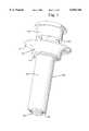
- FIG. 7is an end view of a portion of the trocar assembly according to the present invention.
- FIG. 8is a cross-sectional view of the cannula
- FIG. 9is a cross-sectional view of the lower housing
- FIG. 10is a perspective view of a portion of the cannula sleeve and housing spring of the present invention.
- FIG. 11is a bottom plan view of the housing spring
- FIG. 12is a side view of the obturator, cap member and thrust member according to the present invention, wherein the cap member and thrust member are shown in cross-section;
- FIG. 13is a partially cross-sectional view of an apparatus according to the present invention, wherein the obturator, stabilizer, and housing spring are not shown in cross-section;
- FIG. 14is a perspective view of the thrust member
- FIG. 15is the same view as FIG. 13, wherein the cutting blade has been exposed and is positioned adjacent a tissue wall to be penetrated;
- FIG. 16is the same view as FIG. 15, wherein the cutting blade and cannula sleeve have been urged through a tissue wall into an underlying anatomical cavity;
- FIG. 17is the same view as FIG. 16, wherein the obturator has been released
- FIG. 18is the same view as FIG. 17, wherein the obturator is being removed from the cannula sleeve;
- FIG. 19is the same view of FIG. 18, wherein the obturator has been completely removed, and only the cannula remains in place;
- FIG. 20is the same view as FIG. 19 (with spring 75 shown in cross-section), wherein the cannula release member has been inserted through the cannula sleeve in order to allow for removal of the cannula assembly;
- FIG. 21is a cross-sectional view of the cannula sleeve of FIG. 8, taken along the line 18--18 thereof;
- FIG. 22is a cross-sectional view of the lower portion of the obturator
- FIG. 23is an end view of the trocar assembly shown in FIG. 15;
- FIG. 24is an end view of the trocar assembly of FIG. 19.
- a method of inserting a cannula through a tissue wall into an anatomical cavitycomprising:
- the cannulahaving:
- a sleevehaving a distal end and a longitudinal axis
- a stabilizerpositioned adjacent the distal end of the sleeve, the stabilizer movable between extended and retracted positions;
- the obturatorpositioned at least partially within the sleeve, and having a distal end configured for penetrating tissue;
- the extended stabilizerWhen the stabilizer is in its extended position, at least a portion of the stabilizer extends beyond the outer circumference of the distal end of the cannula sleeve.
- the extended stabilizeralso referred to as undeformed or in its second position
- corresponding diametersimply means that the diameter of the distal end of the sleeve is measured along a line which is parallel to the line defining the maximum cross-sectional diameter of the stabilizer.
- the stabilizerwhen the stabilizer is in its retracted position (also referred to as its deformed or first position), the stabilizer does not extend substantially beyond the outer circumference of the distal end of the cannula sleeve.
- the maximum cross-sectional diameter of the stabilizerwhen the stabilizer is in its deformed position, is substantially equal to or less than the corresponding diameter of the distal end of the cannula sleeve.
- advancement of the obturatorresults in the desired deformation of the stabilizer to its deformed (or retracted) position, and even more preferably the obturator accomplishes this by passing through the interior of the stabilizer such that the obturator deforms the stabilizer to a configuration which allows the obturator to pass therethrough.
- the cannulafurther may comprise a spring-biased retention member spaced away from the distal end of the cannula sleeve, the retention member spring-biased towards the distal end of the cannula sleeve.
- the retention membertherefore comprises a second, external stabilizer, and may be provided as the cannula housing (or a portion thereof).
- the cannulaincludes upper and lower housings, and the lower housing is spring-biased towards the first stabilizer (therefore providing the "retention member").
- the lower housingis selectively spring-biased such that the spring-biasing is activated only upon withdrawal of the obturator away from the distal end of the sleeve.
- the lower housingis preferably configured such that, upon activation of the spring-biasing, the lower housing (or retention member) is urged against the exterior of the tissue wall through which the cannula has been inserted.
- the first stabilizermay comprise an elliptical member which extends away from the distal end of the sleeve.
- the present inventionalso provides a trocar comprising:
- a cannulahaving a distal end, a first stabilizer positioned adjacent the distal end of the cannula, and a second stabilizer spaced away from the distal end;
- the cannulamay be inserted through a tissue wall in order to provide operative access to an underlying anatomical cavity, with the first stabilizer positioned adjacent the tissue wall within the anatomical cavity and the second stabilizer positioned adjacent the tissue wall outside of the anatomical cavity.
- the first and second stabilizersare spring-biased towards each other such that the tissue wall in which the cannula may be positioned will be held (i.e., slightly compressed) between the first and second stabilizers.
- the trocaralso preferably includes an obturator, and it is configured such that advancement of the obturator towards the distal end of the cannula deforms the first stabilizer to a retracted position which facilitates passage of the distal end of the cannula through a tissue wall. Withdrawal of the obturator away from the distal end of the cannula allows the first stabilizer to return to its extended, undeformed position which prevents removal of the cannula from a tissue wall through which it extends.
- the present inventionprovides apparatus and methods for penetrating tissue and creating an opening therein, particularly for creating a tissue opening which provides access to an anatomical cavity within a patient (both human and animal). More particularly, the apparatus and methods of the present invention may be employed to create a tissue opening in which a cannula is positioned, thereby providing a channel through which other instruments may be inserted (e.g., and endoscope, a surgical grasper, etc.) into the patient's body. When used in this manner, the apparatus of the present invention generally comprises a trocar assembly which includes the cannula which is positioned within the tissue opening.
- anatomical cavityrefers to any actual or potential space within a patient, including, for example, the abdominal cavity (both intra- and extra-peritoneal), the thoracic cavity, organs, lumens, and even potential spaces (such as those often accessed during arthroscopic or laparoscopic procedures; for example, the space of Retzius).
- tissue wallgenerally refers to the layer of tissue overlying the anatomical cavity being accessed. For example, when the intra-peritoneal abdominal cavity is to be accessed, the tissue wall through which the cannula is inserted will include the outer layer of skin, the fascia, abdominal muscle, any layers of fat which are present, and the peritoneum.
- the apparatus of the present inventionemploys a cannula stabilizer which, when deployed within the anatomical cavity, prevents inadvertent removal or dislodgement of the cannula from the anatomical cavity into which it extends.
- a preferred embodiment of the trocar of the present inventionalso includes a spring-biased housing which bears against the outer surface of the tissue wall after the cannula has been inserted, thereby providing external cannula stabilization. In this manner, the tissue wall surrounding the opening therein will be compressed between the internal stabilizer and the spring-biased housing (the "second" stabilizer), thereby maintaining the cannula at the proper location.
- FIG. 1is a perspective view of a stabilized trocar assembly 30 according to one embodiment of the present invention.
- a cannulawhich includes a cannula sleeve 40, and an upper housing 45 having a diameter greater than that of sleeve 40.
- An obturator (or cutting blade assembly) 60is positioned within cannula sleeve 40. Obturator 60 is not visible in FIG. 1, since it is in its retracted position completely within sleeve 40.
- trocar assembly 30 of the present inventionincludes a cannula stabilizer 80 positioned adjacent distal end 41 of sleeve 40.
- adjacentmeans at or next to, and therefore stabilizer 80 is shown immediately next to distal end 41. It will be understood, however, that stabilizer 80 may even be provided on sleeve 40, coextensive with, or even above, distal end 41. Stabilizer 80 is shown in FIG. 1 in its extended/undeformed (or second) position whereat stabilizer 80 will prevent sleeve 40 from being withdrawn from a tissue opening through which sleeve 40 has been passed. As will be apparent from FIG. 1, in its undeformed position, stabilizer 80 has an outer diameter which is greater than the corresponding diameter of distal end 41 along the same axis.
- stabilizer 80extends beyond the outer wall of distal end 41 of sleeve 40.
- stabilizer 80is automatically deployed (i.e., advances to its extended or undeformed position) upon withdrawal of the obturator, thereby providing a simple mechanism for ensuring that the cannula sleeve will not be inadvertently dislodged during a surgical procedure.
- FIG. 13is a cross-sectional view of trocar assembly 30 of FIG. 1, wherein obturator (or cutting blade assembly) 60 and springs 53 and 75 are not shown in cross-section for purposes of clarity.
- housing spring 53extends about the circumference of cannula sleeve 40.
- Trocar assembly 30is shown in FIGS. 1 and 13 in its initial state, as the trocar would be provided to the surgeon.
- obturator 60is shown in its retracted position wherein cutting blade 62 is safely positioned entirely within cannula sleeve 40.
- cap member (or handle) 63is compressed towards flange 47 of upper housing 45, obturator 60 will be urged downwardly such that cutting blade 62 will extend beyond distal end 41 of sleeve 40, as well as stabilizer 80 (as best seen in FIG. 11).
- the cutting bladeWith cutting blade 62 exposed (i.e., extending beyond the lower end of the trocar assembly), the cutting blade may be urged through the tissue wall of an anatomical cavity.
- cannula sleeve 40Since the diameter of cannula sleeve 40 is only slightly greater than the diameter of distal end 64 of obturator 60, cannula sleeve 40 will follow cutting blade 62 through the tissue wall towards the anatomical cavity (as best seen in FIG. 12). Once cutting blade 62 and distal end 41 of cannula sleeve 40 have completely penetrated through the tissue wall into the anatomical cavity, cutting blade assembly 60 may be removed from the trocar assembly, thereby leaving cannula sleeve 40 in place. The hollow interior of cannula sleeve 40 thereafter provides operative access to the anatomical cavity into which distal end 41 of sleeve 40 extends.
- the cannula portion of trocar assembly 30generally comprises a cannula sleeve 40 having a lower (or distal end) 41.
- a housingis attached to sleeve 40 at its upper (or proximal end), and this housing should be larger than sleeve 40 such that it cannot penetrate the tissue wall.
- the housingcomprises an upper housing portion 45 which is attached to, and is integral with, cannula sleeve 40.
- other configurations well-known to those skilled in the artmay be employed, such as a detachable upper housing 45.
- a preferred embodiment of the present inventionalso includes a lower housing 44 which is selectively spring-biased towards distal end 41 of sleeve 40.
- the entire housingmay be selectively spring-biased towards distal end 41, however a preferred embodiment includes upper and lower housings, only one of which may move with respect to cannula sleeve 40.
- cannula sleeve 40should be selected such that its distal end can be readily positioned within the anatomical cavity being accessed with upper housing 45 spaced away from the outer surface of the tissue layer penetrated by the cannula (such as the skin).
- cannula sleeve 40should also be hollow in order to provide an operative port which provides access to the anatomical cavity.
- cannula sleeve 40have a non-circular cross-sectional shape, more preferably an elliptical cross-sectional shape (as best seen in the cross-sectional view of FIG. 21).
- Cannula sleevealso has a pair of cutouts 42 extending lengthwise along the interior of sleeve 40 from distal end 41 towards housing 45. Cutouts 42 are provided on opposite sides of the interior wall of sleeve 40, preferably intersecting the major axis of the elliptical cross-sectional shape of sleeve 40. In other words, cutouts 42 extend along opposite sides of the interior surface of sleeve 40, upwardly away from distal end 41 and parallel to the longitudinal axis of sleeve 40. Preferably, cutouts 42 extend from distal end 41 to a point spaced below upper housing 45, as shown in FIG. 8. As more fully described below, cutouts 42 accommodate the mounting arms 81 of stabilizer 80.
- Upper housing 45is also preferably elliptical in cross-sectional shape, and has an outer wall 57 which extends around, and is spaced away from the outer wall of cannula sleeve 40. In this manner, an annular cavity 46 is provided between outer wall 57 of upper housing 45 and cannula sleeve 40. An inwardly extending lip 48 is provided at the lower end of outer wall 57. An upper wall 50 connects outer wall 57 of upper housing 45 to cannula sleeve 40, at the proximal end of sleeve 40. In this manner, upper wall 50 provides the uppermost wall of annular cavity 46.
- Upper housing 45also includes an outwardly-extending flange 47 which extends radially outward from outer wall 57, as best seen in FIG. 8. Flange 47 provides a convenient means by which the medical practitioner may manipulate the trocar assembly of the present invention.
- FIGS. 12 and 22depict preferred structural details for obturator 60, as well as cap member 63.
- Obturator 60generally comprises an elongate shaft 61, a distal end portion 64 attached to the lower end of shaft 61, and one or more cutting blades 62 which extend away from distal end portion 64.
- cutting blade 62has a pair of sharpened edges which taper upwardly away from pointed tip 72.
- Various other configurations for the cutting blade portion of obturator 60may also be employed, however, such as the star- or triangular-shape cutting blades described in U.S. Pat. No. 5,215,526. In the embodiment of FIG.
- cutting blade 62may provided by a single, flat piece of metal having a pair of sharpened edges which meet at pointed tip 72. Cutting blade 62 may be secured to distal end portion 64 by a variety of means, such as molding distal end portion 64 about cutting blade 62. Of course distal end portion 64 and cutting blade 62 may even comprise a single, integral unit wherein distal end portion 64 merely tapers to one or more sharpened leading edges, similar to that shown in U.S. Pat. No. 5,116,353.
- Distal end portion 64 of obturator 60preferably has an elliptical cross-sectional shape which corresponds substantially in shape, and is slightly smaller than the interior of cannula sleeve 40.
- the maximum diameter of distal end portion 64i.e., across the major axis of its elliptical cross-section
- distal end portion 64should also taper towards the sharpened leading edges of cutting blade 62 such that a smooth transition is provided between flat cutting blade 62 and elliptical distal end portion 64.
- the lowermost portion of distal end 64will essentially have an elliptical cone shape, and the uppermost portion of distal end 64 will have an elliptical cylinder shape.
- distal end portion 64since it tapers towards cutting blade 62, will gradually expand the tissue opening as it pass therethrough closely behind cutting blade 62.
- distal end portion 64tapers to nearly the width of sleeve 40, this expansion of the tissue opening as distal end portion 64 is urged therethrough, will allow distal end 41 of cannula sleeve 40 to also pass through the tissue opening created by cutting blade 62, following closely behind distal end portion 64 of obturator 60.
- cutting blade 62 and cannula sleeve 40are urged through the tissue wall simultaneously, with sleeve 40 following closely behind cutting blade 62.
- Conical taper portion 65connects distal end 64 to obturator shaft 61.
- conical taper portion 65may have an elliptical cross-sectional shape where it meets distal end portion 64, and a circular cross-sectional shape where it meets shaft 61.
- conical taper portion 65provides a smooth transition between shaft 61, and the larger diameter distal end portion 64. In this manner, conical taper portion 65 provides a sloped shoulder which, as further described below, facilitates release of the spring-biased lower housing 44.
- cap member 63At its upper (or proximal) end, shaft 61 of obturator 60 is attached to cap member (or handle) 63.
- cap member 63 and obturator 60may be formed as an integral unit.
- Cap member 63generally comprises a hollow housing which includes circumferential sidewall 73, upper wall 66 and lower wall 70, all of which define an interior volume 74.
- Interior volume 74is sized to accommodate a thrust member 67, as well as an obturator spring 75.
- upper wall 66 of cap member 63may be formed separately such that thrust member 67 and obturator spring 75 may be easily positioned within interior volume 74, as shown, and upper wall 66 thereafter attached to cap sidewall 73.
- thrust member 67generally comprises a flat plate 68 having a shape corresponding to the cross-sectional shape of interior volume 74 of cap member 63 (e.g., elliptical or circular).
- Two or more thrust arms 69extend downwardly away from plate 68 of thrust member 67.
- Thrust arms 69are positioned and configured so as to be alignable with, and slidable within a pair of slots 71 provided in lower wall 70 of cap member 63.
- thrust plate 68 of thrust member 67may be positioned within interior volume 74 of cap member 63, with each thrust arm 69 extending downwardly through a slot 71 (as best seen in FIG. 12).
- Obturator spring 75is positioned between plate 68 of thrust member 67, and upper wall 66 of cap member 63, and therefore will spring-bias thrust member 67 in the downward direction (i.e., towards cutting blade 62).
- obturator 60should be positioned within cannula sleeve 40 such that the lowermost ends of thrust arms 69 will bear against the upper surface of the cannula assembly.
- lower ends 76 of thrust arms 69bear against upper wall 50 of upper housing 45.
- thrust member 67is spring biased downwardly
- cap member 63is correspondingly biased in the upward direction since obturator spring 75 bears against upper wall 66 of cap member 63. Since obturator 60 is secured to cap member 63, obturator 60 will likewise be spring biased upwardly such that cutting blade 62 is normally safely maintained within cannula shaft 40, as shown in FIG. 13.
- cap member 63 and obturator 60will be urged downwardly such that cutting blade 62 will extend beyond distal end 41 of cannula 40, as well as beyond stabilizer 80.
- the extent of downward movement of cap member 63 and obturator 60is limited since lower wall 70 of cap member 63 will contact upper wall 50 of upper housing 45.
- cap member 63 and obturator 60should be sized such that when cap member 63 has been depressed to its fullest extent, cutting blade 62 will extend just beyond stabilizer 80, as seen FIG. 15. It will also be noted that forces G and H may be readily applied by the medical practitioner grasping flange 47 with his fingers and exerting force G with the palm of the same hand bearing against cap member 63.
- the medical practitionerwill often first create a small incision in the outer layer 83 of the tissue wall 84 to be penetrated, particularly when this tissue wall includes an outer layer of skin 83. Thereafter, forces G and H will be applied to the assembly, as shown in FIG. 15, thereby exposing cutting blade 62. At the same time, the medical practitioner will urge cutting blade 62 against the tissue wall to be penetrated, and thereafter apply a downward force in order to urge cutting blade 62 through the tissue wall.
- cap member 63 and obturator 60may then be completely removed from the cannula, as shown in FIG. 18. This results in the cannula remaining in place, with cannula sleeve 40 extending completely through the tissue wall in order to provide operative access to the underlying anatomical cavity.
- the trocar assembly of the present inventionmay be employed with the backstop assembly described in Applicants' co-pending patent application Ser. No. 09/065,254, which was filed on Apr. 23, 1998, and which is incorporated herein by way of reference.
- the backstop lighted backstop assembly depicted in FIGS. 30-36 of that applicationmay first be positioned within the anatomical cavity, and the trocar of the present invention thereafter driven through the tissue wall until cutting blade 62 meets the backstop. In this manner, over-penetration of the sharp cutting blade will be prevented.
- FIG. 2is a perspective view of first (or internal) stabilizer 80 of the present invention, wherein the stabilizer is shown in its extended/undeformed (or second) position.
- stabilizer 80comprises an elliptical strip (i.e., an elliptical cylinder) of an elastic material.
- stabilizer 80is made from a material possessing shape memory, such that stabilizer 80 may be readily deformed, and will return to its extended position shown in FIG.
- stabilizer 80is a shape memory metal, such as nitinol. Although nitinol possesses significant shape memory, other types of metals possessing less memory may also be employed, such as stainless steel. Of course other materials, such as plastic, also possess some shape memory, and may therefore be used to produced stabilizer 80.
- shape memory metalsuch as nitinol. Although nitinol possesses significant shape memory, other types of metals possessing less memory may also be employed, such as stainless steel. Of course other materials, such as plastic, also possess some shape memory, and may therefore be used to produced stabilizer 80.
- the maximum diameter of stabilizer 80corresponds to its major axis and is defined at A.
- the minimum diameter of stabilizer 80 when it is in its extended positionis that defined by the minor axis of the elliptical cross-sectional shape. Since stabilizer 80 is preferably made from a flexible, shape memory material, a force F applied in the radially outward directions shown in FIG. 2 will cause stabilizer 80 to deform. When force F is applied in this manner, stabilizer 80 will be deformed to its retracted (or first) position, as shown in FIGS. 3 and 5. As will be apparent, the major and minor axis of elliptical stabilizer 80 are essentially switched.
- the maximum diameter of stabilizer 80 when it is in its deformed positionis positioned 90° from the location of the maximum diameter when stabilizer 80 is in its undeformed position (FIGS. 2 and 4).
- stabilizer 80protrudes beyond the outer circumference of distal end 41 of sleeve 40 only when in its undeformed position.
- When stabilizer 80 is in its deformed (or retracted) positionit will substantially not protrude beyond the outer circumference of distal end 41 of sleeve 40.
- FIG. 4is a top plan view of stabilizer 80 oriented in the manner shown in FIG. 2, while FIG. 5 is a top plan view of stabilizer 80 shown in its orientation of FIG. 3.
- FIG. 4is a top plan view of stabilizer 80 oriented in the manner shown in FIG. 2
- FIG. 5is a top plan view of stabilizer 80 shown in its orientation of FIG. 3.
- the minor axis of the ellipsedefines the minimum diameter B of stabilizer 80, as shown in FIG. 4.
- elliptical stabilizer 80When a force F is applied from the interior of stabilizer 80 radially outward along minor axis B, as shown, elliptical stabilizer 80 will be deformed into the configuration shown in FIG. 5. Upon such deformation, the maximum diameter of stabilizer 80 is now defined at B, while the minimum diameter is defined at A. As will be more fully described below, the deformed (or first) position for stabilizer 80 shown in FIG. 5 allows for insertion of the trocar cannula through a tissue opening into the patient. In contrast, when stabilizer 80 is in its undeformed (or second) position shown in FIG. 4, stabilizer 80 will prevent withdrawal or inadvertent dislodgment of the trocar cannula from the patient.
- Mounting arms 81extend upwardly away from stabilizer 80.
- Mounting arms 81can take a variety of configurations, and that shown is merely one presently contemplated embodiment.
- Mounting arms 81generally comprise an elongate strip of material, and may comprise a shape memory metal such as that used for stabilizer 80.
- mounting arms 81may each comprise a flat strip of material, it is preferred that mounting arms 81 have a slight curvature corresponding to the interior curvature of cutouts 42 within cannula sleeve 40.
- Various other configurationsmay be employed, however, since the mounting arms 81 merely provide a means for positioning stabilizer 80 adjacent distal end 41 of cannula sleeve 40.
- FIG. 6depicts an alternative embodiment which may be employed.
- Stabilizer 80 of FIG. 6has the same configuration as that previously described.
- mounting arms 181are formed separately from stabilizer 80 and each comprises a strip of material which is folded around stabilizer 80 on opposite sides thereof. The portion of each mounting arm 181 which is wrapped around stabilizer 80 may then be welded, bolted, glued or otherwise secured to itself above stabilizer 80. In this manner, each mounting arm 181 has a loop at its lower end through which stabilizer 80 passes. Stabilizer 80 at 182 need not be rigidly secured within the lower loop on each mounting arm 181, and may therefore be free to slide therein.
- mounting arms 181may be made from a variety of materials, including various metals or plastics, and, since mounting arms 181 are not integrally formed with stabilizer 80, they need not be of the same material as stabilizer 80.
- cannula sleeve 40preferably has a pair of cutouts extending upwardly from distal end 41 towards upper housing 45. Cutouts 42 should correspond in size and shape to mounting arms 81 (or 181) of stabilizer 80. In this manner, mounting arms 81 may be secured within cutouts 42 on sleeve 40 in order to position stabilizer 80 adjacent distal end 41 of cannula sleeve 40.
- cutouts 42are preferably positioned at opposite ends of the major axis of the elliptical cross-section of cannula sleeve 40, the minor axis of elliptical stabilizer 80 (when stabilizer 80 is in its undeformed state shown in FIG.
- distal end portion 64 of obturator 60will bear against mounting arms 81 and eventually the interior of stabilizer 80. In this manner, distal end portion 64 will provide a deformation force corresponding to force F shown in FIGS. 2 and 4. In fact, even the force imparted against mounting arms 81 above stabilizer 80 by distal end portion 64 will cause stabilizer 80 to begin to deform since mounting arms 81 are attached to stabilizer 80. Thus, as obturator 60 is urged downwardly, distal end portion 64 will cause obturator 80 to resiliently flex to its deformed (or first) position of FIGS. 3 and 5.
- stabilizer 80should be sized such that when stabilizer 80 is in its deformed state, its diameter along any axis should preferably be substantially equal to or less than the diameter of distal end 41 of cannula 40 along a corresponding axis (i.e., an axis parallel to that used to measure the diameter of stabilizer 80). In other words, when stabilizer 80 is in its deformed state, no portion of stabilizer 80 should substantially extend beyond the outer circumference of distal end 41 of sleeve 40. In addition, stabilizer 80 should be dimensioned such that distal end portion 64 of obturator 60 may freely pass through the interior of stabilizer 80, as shown in FIG. 7.
- stabilizer 80will return to its undeformed (or second) position. When this occurs, the location of the maximum diameter across stabilizer 80 will no longer be aligned with the axis defining the maximum cross-sectional diameter of distal end 41 of cannula sleeve 40. In other words, stabilizer 80 will protrude beyond the outer circumference of distal end 41 of cannula sleeve 40, as shown in FIG. 1. In this manner, stabilizer 80 acts as an internal (i.e., within the anatomical cavity) stabilizer which prevents cannula 40 from being withdrawn from the tissue opening.
- a release member 90is provided.
- Release member 90essentially comprises an elongate rod having a blunt tip 92 at one end, and a handle portion 91 at its opposite end. Handle portion 91 should be sized and configured to allow for easy manipulation, as well as to prevent over insertion of release member 90.
- At least the distal end portion (i.e., that portion adjacent blunt tip 92) of release member 90should have a cross-sectional size and shape which is slightly less than the interior dimensions of cannula sleeve 40.
- release member 90As release member 90 is urged downwardly through the interior of cannula sleeve 40, its distal end portion will bear against mounting arms 81 of stabilizer 80, as well as the interior of stabilizer 80 itself, thereby providing deformation force F shown in FIG. 2.
- release member 90When release member 90 is urged downwardly to its full extent, its distal end portion will cause stabilizer 80 to move to its fully deformed condition (FIG. 3) wherein its exterior dimensions are substantially equal to or less than that of distal end 41 of cannula sleeve 40. In this manner, cannula 40 may then be removed from the tissue opening without interference from stabilizer 80.
- the trocar assembly of the present inventionalso includes an "upper stabilizer" which is positioned on the opposite side of the tissue wall from stabilizer 80 (typically, against the patient's skin 83).
- this upper stabilizercomprises a spring-loaded lower housing 44 which is positioned at least partially within upper housing 45.
- Lower housing 44comprises a cup-like member (FIG. 9) having a flange 51 about its upper edge, and a bore 56 in its bottom wall 52. Bore 56 is sized to slidingly receive cannula sleeve 40 therein.
- lower housing 44is slidably positioned within cavity 46 of upper housing 45, with a portion of lower housing 44 preferably extending beyond inner lip 48 on upper housing 45.
- Lower housing 44is free to slide downwardly towards distal end 41 of cannula sleeve 40, however the extent of downward movement is limited by flange 51 of lower housing 44 bearing against inner lip 48 of upper housing 45.
- Lower housing 44is also spring-biased towards distal end 41 of cannula sleeve 40, however this spring-biasing is normally deactivated as long as obturator 60 remains substantially within sleeve 40.
- This selective spring-biasingis provided by helical housing spring 53 which is shown in FIGS. 10 and 11.
- Helical housing spring 53preferably has a circular lower revolution 54, and a plurality of elliptical upper revolutions 55. Elliptical upper revolutions 55 are sized such that helical housing spring 53 may extend about the circumference of cannula sleeve 40, as best shown in FIG. 10.
- Cannula sleeve 40has a pair of notches 40 positioned on opposite sides thereof, above cutouts 42. Notches 49 extend to the interior of cannula sleeve 40, as best seen in FIG. 8.
- Lower circular revolution 54 of housing spring 53extends about the circumference of cannula sleeve 40 and through each notch 49, as shown in FIG. 10, such that a portion of lower revolution 54 protrudes into the interior of sleeve 40.
- lower revolution 54 of spring 53may, in addition to being circular, comprise an elliptical shape which is less oblong than upper revolutions 55. In any event, lower revolution 54 of spring 53 is positioned within notches 49 such that lower revolution 54 extends into the interior of cannula sleeve 40.
- shaft 61 of obturator 60has a diameter significantly smaller than the interior diameter of cannula shaft 40, lower revolution 54 of housing spring 53 will not interfere with passage of shaft 61.
- conical taper portion 65 of distal end portion 64 of the obturatorwill be urged against those portions of lower revolution 54 of spring 53 which extends through notches 49 into the interior of the cannula sleeve.
- the tapered wallswill urge lower revolution 54 out of notches 49.
- helical spring 53is released and will bear against bottom wall 52 of lower housing 44 thereby urging bottom wall 52 towards the patient's skin surrounding the tissue opening. Simultaneously, housing spring 53 will also bear against upper wall 50 of upper housing 45. Since upper housing 45 is attached to cannula sleeve 40, the upper force provided by housing spring 53 will, in turn, urge cannula sleeve 40 (and hence stabilizer 80) upwardly.
- Stabilizer 80limits the upward movement of cannula sleeve 40, and therefore cannula sleeve 40 is urged upwardly until stabilizer 80 bears against the interior surface 86 of tissue wall 84 surrounding the opening through which cannula sleeve 40 has passed.
- distal end 41 of cannula sleeve 40will therefore be located substantially coextensive with interior surface 86 of tissue wall 84, as shown in FIG. 18.
- the trocar of the present inventionthus provides both upper and lower stabilizers which are spring-biased towards one another. In this manner, the tissue wall surrounding the opening through which cannula sleeve 40 is positioned will essentially be compressed between housing 44 and stabilizer 80, thereby insuring that cannula sleeve 40 will not become dislodged.
- a marquise-shaped opening 95is provided at the lower end of the device of the present invention.
- Marquise-opening 95can readily accommodate endoscopes and other surgical instruments currently used through trocar cannulas, since such instruments are typically circular in cross-sectional shape.
- the diameter of distal end 41 of cannula sleeve 40 and stabilizer 80 along each of their minor axisis slightly greater than the maximum cross-sectional diameter of the surgical instrument, such instrument can be readily employed through the trocar cannula of the present invention.
- stopcock valves and other portsmay also be provided on the cannula sleeve and/or either housing, as is well-known to those skilled in the art (and as shown, for example, in U.S. Pat. No. 5,454,791.
- various types of safety shieldsmay also be included, such as that shown in U.S. Pat. No. 5,215,526.
- the elliptical shape for stabilizer 80is but merely one preferred embodiment, and it will be understood that other shapes (particularly other non-circular shapes) may be employed without departing from the scope of the present invention, particularly if the particular shape can be readily deformed from a cannula retaining to a cannula passing configuration (and back again).
Landscapes
- Health & Medical Sciences (AREA)
- Surgery (AREA)
- Life Sciences & Earth Sciences (AREA)
- Biomedical Technology (AREA)
- Nuclear Medicine, Radiotherapy & Molecular Imaging (AREA)
- Engineering & Computer Science (AREA)
- Pathology (AREA)
- Heart & Thoracic Surgery (AREA)
- Medical Informatics (AREA)
- Molecular Biology (AREA)
- Animal Behavior & Ethology (AREA)
- General Health & Medical Sciences (AREA)
- Public Health (AREA)
- Veterinary Medicine (AREA)
- Surgical Instruments (AREA)
Abstract
Description
Claims (21)
Priority Applications (1)
| Application Number | Priority Date | Filing Date | Title |
|---|---|---|---|
| US09/094,305US6056766A (en) | 1998-06-09 | 1998-06-09 | Stabilized trocar, and method of using same |
Applications Claiming Priority (1)
| Application Number | Priority Date | Filing Date | Title |
|---|---|---|---|
| US09/094,305US6056766A (en) | 1998-06-09 | 1998-06-09 | Stabilized trocar, and method of using same |
Publications (1)
| Publication Number | Publication Date |
|---|---|
| US6056766Atrue US6056766A (en) | 2000-05-02 |
Family
ID=22244390
Family Applications (1)
| Application Number | Title | Priority Date | Filing Date |
|---|---|---|---|
| US09/094,305Expired - LifetimeUS6056766A (en) | 1998-06-09 | 1998-06-09 | Stabilized trocar, and method of using same |
Country Status (1)
| Country | Link |
|---|---|
| US (1) | US6056766A (en) |
Cited By (55)
| Publication number | Priority date | Publication date | Assignee | Title |
|---|---|---|---|---|
| US6464690B1 (en) | 2000-10-11 | 2002-10-15 | Popcab, Llc | Port off-pump beating heart coronary artery bypass heart stabilization system |
| US6500170B2 (en)* | 2000-10-11 | 2002-12-31 | Popcab, Llc | Instrument stabilizer for through-the-port surgery |
| US6503245B2 (en) | 2000-10-11 | 2003-01-07 | Medcanica, Inc. | Method of performing port off-pump beating heart coronary artery bypass surgery |
| US20030083666A1 (en)* | 2000-03-15 | 2003-05-01 | Thomas Zdeblick | Methods and instruments for laparoscopic spinal surgery |
| US6579281B2 (en) | 2000-10-11 | 2003-06-17 | Popcab, Llc | Instrument stabilizer for through-a-port surgery |
| US6582420B2 (en) | 2000-10-11 | 2003-06-24 | Popcab, Llc | Intercostal lockable directable port device |
| US6592573B2 (en) | 2000-10-11 | 2003-07-15 | Popcab, Llc | Through-port heart stabilization system |
| US6695815B2 (en) | 2000-02-23 | 2004-02-24 | Stephen P. Moenning | Minimally invasive medical apparatus for dispensing a biologically active compound and an associated medical procedure for dispensing a biologically active compound |
| US20040162321A1 (en)* | 2003-01-03 | 2004-08-19 | Boehringer Ingelheim Pharmaceuticals, Inc. | Glucocorticoid mimetics, methods of making them, pharmaceutical compositions, and uses thereof |
| US20040167473A1 (en)* | 2000-02-23 | 2004-08-26 | Moenning Stephen P. | Trocar-cannula complex, cannula and method for delivering fluids during minimally invasive surgery |
| US6783513B2 (en) | 2001-05-17 | 2004-08-31 | Stephen P. Moenning | Body cavity access assembly and an associated medical procedure for dispensing a liquid |
| US20050119613A1 (en)* | 2000-02-23 | 2005-06-02 | Moenning Stephen P. | Fluid delivery trocar-cannula complex, fluid delivery accessory, and method for delivering fluids during minimally invasive surgery |
| US20050251190A1 (en)* | 2000-05-16 | 2005-11-10 | Mcfarlane Richard H | Penetrating tip for trocar assembly |
| US20050273116A1 (en)* | 2003-01-31 | 2005-12-08 | Simpson Philip J | System and method for rapid placement of chest tubes |
| US20060025749A1 (en)* | 2000-02-23 | 2006-02-02 | Moenning Stephen P | Trocar-cannula complex, cannula and method for delivering fluids during minimally invasive surgery |
| US20080249467A1 (en)* | 2007-04-05 | 2008-10-09 | Daniel Rogers Burnett | Device and Method for Safe Access to a Body Cavity |
| US20080319261A1 (en)* | 2007-06-20 | 2008-12-25 | Flavio Lucini | Cannula device for endoscopic surgical operations |
| US20090093850A1 (en)* | 2007-10-05 | 2009-04-09 | Tyco Healthcare Group Lp | Expanding seal anchor for single incision surgery |
| US20100010449A1 (en)* | 2008-07-09 | 2010-01-14 | Kyphon Sarl | Cannula Stabilization Device, System, And Method Of Use |
| US20100048994A1 (en)* | 2007-04-11 | 2010-02-25 | Okoniewski Gregory G | Visualized entry trocar with moving blade |
| AU2004209999B2 (en)* | 2003-01-31 | 2010-04-29 | Walter Dean Gillespie | System and method for rapid placement of chest tubes |
| US20100113883A1 (en)* | 2008-10-30 | 2010-05-06 | Widenhouse Christopher W | Surgical access port with adjustable ring geometry |
| US20100234806A1 (en)* | 2009-03-10 | 2010-09-16 | Tyco Healthcare Group Lp | Port fixation using expandable threads |
| US20100261970A1 (en)* | 2009-04-08 | 2010-10-14 | Ethicon Endo-Surgery, Inc. | Retractor with flexible sleeve |
| US20100261972A1 (en)* | 2009-04-08 | 2010-10-14 | Ethicon Endo-Surgery, Inc. | Surgical Access Device with One Time Seal |
| US20100262080A1 (en)* | 2009-04-08 | 2010-10-14 | Ethicon Endo-Surgery, Inc. | Surgical access device having removable and replaceable components |
| US20100261974A1 (en)* | 2009-04-08 | 2010-10-14 | Ethicon Endo-Surgery, Inc. | Methods and devices for providing access into a body cavity |
| US20100268162A1 (en)* | 2009-04-15 | 2010-10-21 | Ethicon Endo-Surgery, Inc. | Cannula with sealing elements |
| US20100274093A1 (en)* | 2009-04-22 | 2010-10-28 | Ethicon Endo-Surgery, Inc. | Methods and devices for identifying sealing port size |
| US20100280327A1 (en)* | 2009-05-04 | 2010-11-04 | Ethicon Endo-Surgery, Inc. | Methods and devices for providing access through tissue to a surgical site |
| US20100312060A1 (en)* | 2009-06-05 | 2010-12-09 | Ethicon Endo-Surgery, Inc. | Interlocking seal components |
| US20100312062A1 (en)* | 2009-06-05 | 2010-12-09 | Ethicon Endo-Surgery, Inc. | Multi-planar obturator with foldable retractor |
| US20100312189A1 (en)* | 2009-06-05 | 2010-12-09 | Ethicon Endo-Surgery, Inc. | Flexible cannula devices and methods |
| US20100312063A1 (en)* | 2009-06-05 | 2010-12-09 | Ethicon Endo-Surgery, Inc. | Methods and devices for accessing a body cavity using a surgical access device with modular seal components |
| US20100312061A1 (en)* | 2009-06-05 | 2010-12-09 | Ethicon Endo-Surgery, Inc. | Methods and devices for providing access through tissue to a surgical site |
| US20100312064A1 (en)* | 2009-06-05 | 2010-12-09 | Ethicon Endo-Surgery, Inc. | Retractor with integrated wound closure |
| US20100312065A1 (en)* | 2009-06-05 | 2010-12-09 | Ethicon Endo-Surgery, Inc. | Active seal components |
| US20110046547A1 (en)* | 2002-11-12 | 2011-02-24 | Mantle Ross E | Device for the Extravascular Recirculation of Liquid in Body Cavities |
| US8033995B2 (en) | 2009-06-05 | 2011-10-11 | Ethicon Endo-Surgery, Inc. | Inflatable retractor with insufflation and method |
| US8357085B2 (en) | 2009-03-31 | 2013-01-22 | Ethicon Endo-Surgery, Inc. | Devices and methods for providing access into a body cavity |
| EP1971378A4 (en)* | 2005-10-21 | 2013-10-02 | Velomedix Inc | Method and apparatus for peritoneal hypothermia and/or resuscitation |
| USD724199S1 (en)* | 2012-08-30 | 2015-03-10 | Guided Therapeutics, Inc. | Medical diagnostic stand off tube |
| US9005116B2 (en) | 2006-04-05 | 2015-04-14 | Ethicon Endo-Surgery, Inc. | Access device |
| EP1284761B1 (en)* | 2000-05-16 | 2015-07-01 | Teleflex Medical Incorporated | Obturator comprising a tip end having an elliptical cross-section |
| US9271752B2 (en) | 2013-03-13 | 2016-03-01 | Swan Valley Medical Incorporated | Method and apparatus for placing a cannula in a bladder |
| US20160235436A1 (en)* | 2015-02-18 | 2016-08-18 | Jon Kiev | Device and method for access to interior body regions |
| US20160235437A1 (en)* | 2015-02-18 | 2016-08-18 | Jon Kiev | Device and method for access to interior body regions |
| US9622670B2 (en) | 2010-07-09 | 2017-04-18 | Potrero Medical, Inc. | Method and apparatus for pressure measurement |
| US20170106175A1 (en)* | 2006-05-18 | 2017-04-20 | Cannuflow, Inc. | Anti-Extravasation Surgical Portal Plug |
| USD794779S1 (en)* | 2012-10-12 | 2017-08-15 | Magnolia Medical Technologies, Inc. | Bodily-fluid sampling device |
| US9907569B2 (en) | 2006-10-06 | 2018-03-06 | Conmed Corporation | Trocar assembly with pneumatic sealing |
| US10779857B2 (en) | 2018-04-04 | 2020-09-22 | Aok Innovations, Llc | Device and method for access to interior body regions |
| US11529167B2 (en) | 2015-07-25 | 2022-12-20 | Aok Innovations, Llc | Device and method for access to interior body regions |
| US11800992B2 (en) | 2007-04-05 | 2023-10-31 | Theranova, Llc | Device and method for safe access and automated therapy |
| US11963692B2 (en) | 2021-04-30 | 2024-04-23 | Aok Innovations, Llc | Body cavity access device |
Citations (39)
| Publication number | Priority date | Publication date | Assignee | Title |
|---|---|---|---|---|
| US4762519A (en)* | 1986-08-18 | 1988-08-09 | Erintrud Frimberger | Apparatus for placing a feeding tube in the stomach of the human or animal body |
| US4826481A (en)* | 1987-05-27 | 1989-05-02 | Abbott Labs. | Enteral feeding device |
| US4869717A (en)* | 1988-04-25 | 1989-09-26 | Adair Edwin Lloyd | Gas insufflation needle with instrument port |
| US5002557A (en)* | 1989-04-06 | 1991-03-26 | Hasson Harrith M | Laparoscopic cannula |
| US5066280A (en)* | 1987-09-30 | 1991-11-19 | Technosystem Limited | Syringes |
| US5112310A (en)* | 1991-02-06 | 1992-05-12 | Grobe James L | Apparatus and methods for percutaneous endoscopic gastrostomy |
| US5116353A (en)* | 1990-10-05 | 1992-05-26 | United States Surgical Corporation | Safety trocar |
| US5122122A (en)* | 1989-11-22 | 1992-06-16 | Dexide, Incorporated | Locking trocar sleeve |
| US5152749A (en)* | 1991-06-28 | 1992-10-06 | American Medical Systems, Inc. | Instrument placement apparatus |
| US5158543A (en)* | 1990-10-30 | 1992-10-27 | Lazarus Harrison M | Laparoscopic surgical system and method |
| US5167627A (en)* | 1990-09-13 | 1992-12-01 | Abbott Laboratories | Stoma creator gastrostomy device and method for placement of a feeding tube |
| US5176697A (en)* | 1989-04-06 | 1993-01-05 | Hasson Harrith M | Laparoscopic cannula |
| US5215526A (en)* | 1988-07-06 | 1993-06-01 | Ethicon, Inc. | Safety trocar |
| US5271380A (en)* | 1990-11-06 | 1993-12-21 | Siegfried Riek | Penetration instrument |
| US5300036A (en)* | 1991-08-30 | 1994-04-05 | Origin Medsystems, Inc. | Trocar with multiple converters and detachable obturator |
| US5318585A (en)* | 1990-10-05 | 1994-06-07 | United States Surgical Corporation | Safety trocar |
| US5334150A (en)* | 1992-11-17 | 1994-08-02 | Kaali Steven G | Visually directed trocar for laparoscopic surgical procedures and method of using same |
| US5336176A (en)* | 1991-12-06 | 1994-08-09 | Inbae Yoon | Automatic retractable safety penetrating instrument |
| US5338302A (en)* | 1993-05-03 | 1994-08-16 | Hasson Harrith M | Vaginal stabilizer cannula |
| US5342382A (en)* | 1991-01-15 | 1994-08-30 | Ethicon, Inc. | Surgical trocar |
| US5343874A (en)* | 1991-09-27 | 1994-09-06 | Applied Medical Technology, Inc. | Tract measuring device |
| US5348541A (en)* | 1993-05-05 | 1994-09-20 | Lyell Mark S | Suprapubic catheter placement apparatus (lyell sound) |
| US5366445A (en)* | 1993-03-30 | 1994-11-22 | Habley Medical Technology Corp. | Trocar with rotating safety shield |
| US5370625A (en)* | 1989-08-15 | 1994-12-06 | United States Surgical Corporation | Trocar guide tube positioning device |
| US5407427A (en)* | 1992-06-16 | 1995-04-18 | Loma Linda University Medical Center | Trocar facilitator for endoscopic surgery |
| USD358209S (en) | 1992-11-30 | 1995-05-09 | Marlow Surgical Technologies, Inc. | Disposable surgical trocar |
| US5431676A (en)* | 1993-03-05 | 1995-07-11 | Innerdyne Medical, Inc. | Trocar system having expandable port |
| US5431638A (en)* | 1991-04-10 | 1995-07-11 | United States Surgical Corporation | Energy dissipation device |
| US5454791A (en)* | 1993-09-07 | 1995-10-03 | United States Surgical Corporation | Trocar with tissue penetration pressure indicator |
| US5514091A (en)* | 1988-07-22 | 1996-05-07 | Yoon; Inbae | Expandable multifunctional manipulating instruments for various medical procedures |
| US5645556A (en)* | 1990-12-18 | 1997-07-08 | Yoon; Inbae | Safety penetrating instrument with triggered penetrating member retraction and single or multiple safety member protrusion |
| US5690664A (en)* | 1993-09-13 | 1997-11-25 | United States Surgical Corporation | Trocar having movable blade |
| US5690663A (en)* | 1994-08-25 | 1997-11-25 | Ethicon Endo-Surgery Inc. | Safety trocar |
| US5697946A (en)* | 1994-10-07 | 1997-12-16 | Origin Medsystems, Inc. | Method and apparatus for anchoring laparoscopic instruments |
| US5707362A (en)* | 1992-04-15 | 1998-01-13 | Yoon; Inbae | Penetrating instrument having an expandable anchoring portion for triggering protrusion of a safety member and/or retraction of a penetrating member |
| US5713869A (en)* | 1995-03-08 | 1998-02-03 | Morejon; Orlando | Trocar assembly |
| US5725553A (en)* | 1996-02-29 | 1998-03-10 | Moenning; Stephen P. | Apparatus and method for protecting a port site opening in the wall of a body cavity |
| US5807338A (en)* | 1995-10-20 | 1998-09-15 | United States Surgical Corporation | Modular trocar system and methods of assembly |
| US5843115A (en)* | 1996-10-28 | 1998-12-01 | Morejon; Orlando | Trocar insertion device |
- 1998
- 1998-06-09USUS09/094,305patent/US6056766A/ennot_activeExpired - Lifetime
Patent Citations (41)
| Publication number | Priority date | Publication date | Assignee | Title |
|---|---|---|---|---|
| US4762519A (en)* | 1986-08-18 | 1988-08-09 | Erintrud Frimberger | Apparatus for placing a feeding tube in the stomach of the human or animal body |
| US4826481A (en)* | 1987-05-27 | 1989-05-02 | Abbott Labs. | Enteral feeding device |
| US5066280A (en)* | 1987-09-30 | 1991-11-19 | Technosystem Limited | Syringes |
| US4869717A (en)* | 1988-04-25 | 1989-09-26 | Adair Edwin Lloyd | Gas insufflation needle with instrument port |
| US5399167A (en)* | 1988-07-06 | 1995-03-21 | Ethicon, Inc. | Safety trocar |
| US5215526A (en)* | 1988-07-06 | 1993-06-01 | Ethicon, Inc. | Safety trocar |
| US5514091A (en)* | 1988-07-22 | 1996-05-07 | Yoon; Inbae | Expandable multifunctional manipulating instruments for various medical procedures |
| US5176697A (en)* | 1989-04-06 | 1993-01-05 | Hasson Harrith M | Laparoscopic cannula |
| US5002557A (en)* | 1989-04-06 | 1991-03-26 | Hasson Harrith M | Laparoscopic cannula |
| US5370625A (en)* | 1989-08-15 | 1994-12-06 | United States Surgical Corporation | Trocar guide tube positioning device |
| US5122122A (en)* | 1989-11-22 | 1992-06-16 | Dexide, Incorporated | Locking trocar sleeve |
| US5167627A (en)* | 1990-09-13 | 1992-12-01 | Abbott Laboratories | Stoma creator gastrostomy device and method for placement of a feeding tube |
| US5318585A (en)* | 1990-10-05 | 1994-06-07 | United States Surgical Corporation | Safety trocar |
| US5116353A (en)* | 1990-10-05 | 1992-05-26 | United States Surgical Corporation | Safety trocar |
| US5116353B1 (en)* | 1990-10-05 | 1996-09-10 | Digital Voice Systems Inc | Safety trocar |
| US5158543A (en)* | 1990-10-30 | 1992-10-27 | Lazarus Harrison M | Laparoscopic surgical system and method |
| US5271380A (en)* | 1990-11-06 | 1993-12-21 | Siegfried Riek | Penetration instrument |
| US5645556A (en)* | 1990-12-18 | 1997-07-08 | Yoon; Inbae | Safety penetrating instrument with triggered penetrating member retraction and single or multiple safety member protrusion |
| US5342382A (en)* | 1991-01-15 | 1994-08-30 | Ethicon, Inc. | Surgical trocar |
| US5112310A (en)* | 1991-02-06 | 1992-05-12 | Grobe James L | Apparatus and methods for percutaneous endoscopic gastrostomy |
| US5431638A (en)* | 1991-04-10 | 1995-07-11 | United States Surgical Corporation | Energy dissipation device |
| US5152749A (en)* | 1991-06-28 | 1992-10-06 | American Medical Systems, Inc. | Instrument placement apparatus |
| US5300036A (en)* | 1991-08-30 | 1994-04-05 | Origin Medsystems, Inc. | Trocar with multiple converters and detachable obturator |
| US5343874A (en)* | 1991-09-27 | 1994-09-06 | Applied Medical Technology, Inc. | Tract measuring device |
| US5336176A (en)* | 1991-12-06 | 1994-08-09 | Inbae Yoon | Automatic retractable safety penetrating instrument |
| US5707362A (en)* | 1992-04-15 | 1998-01-13 | Yoon; Inbae | Penetrating instrument having an expandable anchoring portion for triggering protrusion of a safety member and/or retraction of a penetrating member |
| US5407427A (en)* | 1992-06-16 | 1995-04-18 | Loma Linda University Medical Center | Trocar facilitator for endoscopic surgery |
| US5334150A (en)* | 1992-11-17 | 1994-08-02 | Kaali Steven G | Visually directed trocar for laparoscopic surgical procedures and method of using same |
| USD358209S (en) | 1992-11-30 | 1995-05-09 | Marlow Surgical Technologies, Inc. | Disposable surgical trocar |
| US5431676A (en)* | 1993-03-05 | 1995-07-11 | Innerdyne Medical, Inc. | Trocar system having expandable port |
| US5366445A (en)* | 1993-03-30 | 1994-11-22 | Habley Medical Technology Corp. | Trocar with rotating safety shield |
| US5338302A (en)* | 1993-05-03 | 1994-08-16 | Hasson Harrith M | Vaginal stabilizer cannula |
| US5348541A (en)* | 1993-05-05 | 1994-09-20 | Lyell Mark S | Suprapubic catheter placement apparatus (lyell sound) |
| US5454791A (en)* | 1993-09-07 | 1995-10-03 | United States Surgical Corporation | Trocar with tissue penetration pressure indicator |
| US5690664A (en)* | 1993-09-13 | 1997-11-25 | United States Surgical Corporation | Trocar having movable blade |
| US5690663A (en)* | 1994-08-25 | 1997-11-25 | Ethicon Endo-Surgery Inc. | Safety trocar |
| US5697946A (en)* | 1994-10-07 | 1997-12-16 | Origin Medsystems, Inc. | Method and apparatus for anchoring laparoscopic instruments |
| US5713869A (en)* | 1995-03-08 | 1998-02-03 | Morejon; Orlando | Trocar assembly |
| US5807338A (en)* | 1995-10-20 | 1998-09-15 | United States Surgical Corporation | Modular trocar system and methods of assembly |
| US5725553A (en)* | 1996-02-29 | 1998-03-10 | Moenning; Stephen P. | Apparatus and method for protecting a port site opening in the wall of a body cavity |
| US5843115A (en)* | 1996-10-28 | 1998-12-01 | Morejon; Orlando | Trocar insertion device |
Non-Patent Citations (4)
| Title |
|---|
| Brochure: Endopath, Tristar Blunt Tip Surgical Trocar, by Ethicon Endo Surgery, a Johnson & Johnson company, Cincinnati, OH; 1994.* |
| Brochure: Endopath, Tristar Blunt Tip Surgical Trocar, by Ethicon Endo-Surgery, a Johnson & Johnson company, Cincinnati, OH; 1994. |
| Brochure: Flexipath, Flexible Surgical Trocar, by Ethicon Endo Surgery, a Johnson & Johnson company, Cincinnati, OH; 1993.* |
| Brochure: Flexipath, Flexible Surgical Trocar, by Ethicon Endo-Surgery, a Johnson & Johnson company, Cincinnati, OH; 1993. |
Cited By (77)
| Publication number | Priority date | Publication date | Assignee | Title |
|---|---|---|---|---|
| US20050119613A1 (en)* | 2000-02-23 | 2005-06-02 | Moenning Stephen P. | Fluid delivery trocar-cannula complex, fluid delivery accessory, and method for delivering fluids during minimally invasive surgery |
| US6695815B2 (en) | 2000-02-23 | 2004-02-24 | Stephen P. Moenning | Minimally invasive medical apparatus for dispensing a biologically active compound and an associated medical procedure for dispensing a biologically active compound |
| US20060025749A1 (en)* | 2000-02-23 | 2006-02-02 | Moenning Stephen P | Trocar-cannula complex, cannula and method for delivering fluids during minimally invasive surgery |
| US20040111052A1 (en)* | 2000-02-23 | 2004-06-10 | Moenning Stephen P. | Minimally invasive medical apparatus for dispensing a biologically active compound and an associated medical procedure for dispensing a biologically active compound |
| US20040167473A1 (en)* | 2000-02-23 | 2004-08-26 | Moenning Stephen P. | Trocar-cannula complex, cannula and method for delivering fluids during minimally invasive surgery |
| US7179263B2 (en)* | 2000-03-15 | 2007-02-20 | Sdgi Holdings, Inc. | Methods and instruments for laparoscopic spinal surgery |
| US20030083666A1 (en)* | 2000-03-15 | 2003-05-01 | Thomas Zdeblick | Methods and instruments for laparoscopic spinal surgery |
| US20050251190A1 (en)* | 2000-05-16 | 2005-11-10 | Mcfarlane Richard H | Penetrating tip for trocar assembly |
| US8398666B2 (en) | 2000-05-16 | 2013-03-19 | Teleflex Medical Incorporated | Penetrating tip for trocar assembly |
| EP1284761B1 (en)* | 2000-05-16 | 2015-07-01 | Teleflex Medical Incorporated | Obturator comprising a tip end having an elliptical cross-section |
| US6500170B2 (en)* | 2000-10-11 | 2002-12-31 | Popcab, Llc | Instrument stabilizer for through-the-port surgery |
| US6592573B2 (en) | 2000-10-11 | 2003-07-15 | Popcab, Llc | Through-port heart stabilization system |
| US6582420B2 (en) | 2000-10-11 | 2003-06-24 | Popcab, Llc | Intercostal lockable directable port device |
| US6464690B1 (en) | 2000-10-11 | 2002-10-15 | Popcab, Llc | Port off-pump beating heart coronary artery bypass heart stabilization system |
| US6579281B2 (en) | 2000-10-11 | 2003-06-17 | Popcab, Llc | Instrument stabilizer for through-a-port surgery |
| US6503245B2 (en) | 2000-10-11 | 2003-01-07 | Medcanica, Inc. | Method of performing port off-pump beating heart coronary artery bypass surgery |
| US6783513B2 (en) | 2001-05-17 | 2004-08-31 | Stephen P. Moenning | Body cavity access assembly and an associated medical procedure for dispensing a liquid |
| US20110046547A1 (en)* | 2002-11-12 | 2011-02-24 | Mantle Ross E | Device for the Extravascular Recirculation of Liquid in Body Cavities |
| US20040162321A1 (en)* | 2003-01-03 | 2004-08-19 | Boehringer Ingelheim Pharmaceuticals, Inc. | Glucocorticoid mimetics, methods of making them, pharmaceutical compositions, and uses thereof |
| US20050273116A1 (en)* | 2003-01-31 | 2005-12-08 | Simpson Philip J | System and method for rapid placement of chest tubes |
| AU2004209999B2 (en)* | 2003-01-31 | 2010-04-29 | Walter Dean Gillespie | System and method for rapid placement of chest tubes |
| US7811293B2 (en)* | 2003-01-31 | 2010-10-12 | Philip J. Simpson | System and method for rapid placement of chest tubes |
| EP1971378A4 (en)* | 2005-10-21 | 2013-10-02 | Velomedix Inc | Method and apparatus for peritoneal hypothermia and/or resuscitation |
| US9005116B2 (en) | 2006-04-05 | 2015-04-14 | Ethicon Endo-Surgery, Inc. | Access device |
| US20170106175A1 (en)* | 2006-05-18 | 2017-04-20 | Cannuflow, Inc. | Anti-Extravasation Surgical Portal Plug |
| US9907569B2 (en) | 2006-10-06 | 2018-03-06 | Conmed Corporation | Trocar assembly with pneumatic sealing |
| US11800992B2 (en) | 2007-04-05 | 2023-10-31 | Theranova, Llc | Device and method for safe access and automated therapy |
| US20080249467A1 (en)* | 2007-04-05 | 2008-10-09 | Daniel Rogers Burnett | Device and Method for Safe Access to a Body Cavity |
| US20100048994A1 (en)* | 2007-04-11 | 2010-02-25 | Okoniewski Gregory G | Visualized entry trocar with moving blade |
| US20080319261A1 (en)* | 2007-06-20 | 2008-12-25 | Flavio Lucini | Cannula device for endoscopic surgical operations |
| US20090093850A1 (en)* | 2007-10-05 | 2009-04-09 | Tyco Healthcare Group Lp | Expanding seal anchor for single incision surgery |
| US9474518B2 (en) | 2007-10-05 | 2016-10-25 | Covidien Lp | Expanding seal anchor for single incision surgery |
| US8795326B2 (en) | 2007-10-05 | 2014-08-05 | Covidien Lp | Expanding seal anchor for single incision surgery |
| US20100010449A1 (en)* | 2008-07-09 | 2010-01-14 | Kyphon Sarl | Cannula Stabilization Device, System, And Method Of Use |
| US20100113883A1 (en)* | 2008-10-30 | 2010-05-06 | Widenhouse Christopher W | Surgical access port with adjustable ring geometry |
| US20100234806A1 (en)* | 2009-03-10 | 2010-09-16 | Tyco Healthcare Group Lp | Port fixation using expandable threads |
| US7857789B2 (en)* | 2009-03-10 | 2010-12-28 | Tyco Healthcare Group Lp | Port fixation using expandable threads |
| US8357085B2 (en) | 2009-03-31 | 2013-01-22 | Ethicon Endo-Surgery, Inc. | Devices and methods for providing access into a body cavity |
| US20100261974A1 (en)* | 2009-04-08 | 2010-10-14 | Ethicon Endo-Surgery, Inc. | Methods and devices for providing access into a body cavity |
| US20100261970A1 (en)* | 2009-04-08 | 2010-10-14 | Ethicon Endo-Surgery, Inc. | Retractor with flexible sleeve |
| US20100261972A1 (en)* | 2009-04-08 | 2010-10-14 | Ethicon Endo-Surgery, Inc. | Surgical Access Device with One Time Seal |
| US8137267B2 (en) | 2009-04-08 | 2012-03-20 | Ethicon Endo-Surgery, Inc. | Retractor with flexible sleeve |
| US20100262080A1 (en)* | 2009-04-08 | 2010-10-14 | Ethicon Endo-Surgery, Inc. | Surgical access device having removable and replaceable components |
| US8257251B2 (en) | 2009-04-08 | 2012-09-04 | Ethicon Endo-Surgery, Inc. | Methods and devices for providing access into a body cavity |
| US8419635B2 (en) | 2009-04-08 | 2013-04-16 | Ethicon Endo-Surgery, Inc. | Surgical access device having removable and replaceable components |
| US20100268162A1 (en)* | 2009-04-15 | 2010-10-21 | Ethicon Endo-Surgery, Inc. | Cannula with sealing elements |
| US20100274093A1 (en)* | 2009-04-22 | 2010-10-28 | Ethicon Endo-Surgery, Inc. | Methods and devices for identifying sealing port size |
| US20100280327A1 (en)* | 2009-05-04 | 2010-11-04 | Ethicon Endo-Surgery, Inc. | Methods and devices for providing access through tissue to a surgical site |
| US8033995B2 (en) | 2009-06-05 | 2011-10-11 | Ethicon Endo-Surgery, Inc. | Inflatable retractor with insufflation and method |
| US20100312063A1 (en)* | 2009-06-05 | 2010-12-09 | Ethicon Endo-Surgery, Inc. | Methods and devices for accessing a body cavity using a surgical access device with modular seal components |
| US8465422B2 (en) | 2009-06-05 | 2013-06-18 | Ethicon Endo-Surgery, Inc. | Retractor with integrated wound closure |
| US8475490B2 (en) | 2009-06-05 | 2013-07-02 | Ethicon Endo-Surgery, Inc. | Methods and devices for providing access through tissue to a surgical site |
| US8241209B2 (en) | 2009-06-05 | 2012-08-14 | Ethicon Endo-Surgery, Inc. | Active seal components |
| US8795163B2 (en) | 2009-06-05 | 2014-08-05 | Ethicon Endo-Surgery, Inc. | Interlocking seal components |
| US20100312065A1 (en)* | 2009-06-05 | 2010-12-09 | Ethicon Endo-Surgery, Inc. | Active seal components |
| US20100312060A1 (en)* | 2009-06-05 | 2010-12-09 | Ethicon Endo-Surgery, Inc. | Interlocking seal components |
| US20100312064A1 (en)* | 2009-06-05 | 2010-12-09 | Ethicon Endo-Surgery, Inc. | Retractor with integrated wound closure |
| US20100312061A1 (en)* | 2009-06-05 | 2010-12-09 | Ethicon Endo-Surgery, Inc. | Methods and devices for providing access through tissue to a surgical site |
| US9078695B2 (en) | 2009-06-05 | 2015-07-14 | Ethicon Endo-Surgery, Inc. | Methods and devices for accessing a body cavity using a surgical access device with modular seal components |
| US20100312062A1 (en)* | 2009-06-05 | 2010-12-09 | Ethicon Endo-Surgery, Inc. | Multi-planar obturator with foldable retractor |
| US20100312189A1 (en)* | 2009-06-05 | 2010-12-09 | Ethicon Endo-Surgery, Inc. | Flexible cannula devices and methods |
| US8361109B2 (en) | 2009-06-05 | 2013-01-29 | Ethicon Endo-Surgery, Inc. | Multi-planar obturator with foldable retractor |
| US9622670B2 (en) | 2010-07-09 | 2017-04-18 | Potrero Medical, Inc. | Method and apparatus for pressure measurement |
| US9931044B2 (en) | 2010-07-09 | 2018-04-03 | Potrero Medical, Inc. | Method and apparatus for pressure measurement |
| US10758135B2 (en) | 2010-07-09 | 2020-09-01 | Potrero Medical, Inc. | Method and apparatus for pressure measurement |
| USD724199S1 (en)* | 2012-08-30 | 2015-03-10 | Guided Therapeutics, Inc. | Medical diagnostic stand off tube |
| USD794779S1 (en)* | 2012-10-12 | 2017-08-15 | Magnolia Medical Technologies, Inc. | Bodily-fluid sampling device |
| USD841151S1 (en) | 2012-10-12 | 2019-02-19 | Magnolia Medical Technologies, Inc. | Bodily-fluid sampling device |
| US9271752B2 (en) | 2013-03-13 | 2016-03-01 | Swan Valley Medical Incorporated | Method and apparatus for placing a cannula in a bladder |
| US9743952B2 (en)* | 2015-02-18 | 2017-08-29 | Jon Kiev | Device and method for access to interior body regions |
| US9743953B2 (en)* | 2015-02-18 | 2017-08-29 | Jon Kiev | Device and method for access to interior body regions |
| US20160235437A1 (en)* | 2015-02-18 | 2016-08-18 | Jon Kiev | Device and method for access to interior body regions |
| US20160235436A1 (en)* | 2015-02-18 | 2016-08-18 | Jon Kiev | Device and method for access to interior body regions |
| US11529167B2 (en) | 2015-07-25 | 2022-12-20 | Aok Innovations, Llc | Device and method for access to interior body regions |
| US10779857B2 (en) | 2018-04-04 | 2020-09-22 | Aok Innovations, Llc | Device and method for access to interior body regions |
| US11304725B2 (en) | 2018-04-04 | 2022-04-19 | Aok Innovations, Llc | Device and method for access to interior body regions |
| US11963692B2 (en) | 2021-04-30 | 2024-04-23 | Aok Innovations, Llc | Body cavity access device |
Similar Documents
| Publication | Publication Date | Title |
|---|---|---|
| US6056766A (en) | Stabilized trocar, and method of using same | |
| US5676682A (en) | Safety trocar penetrating instrument with conical and/or threaded trocar and safety shield | |
| AU762195B2 (en) | Self-retaining surgical access instrument | |
| US5843115A (en) | Trocar insertion device | |
| US5637096A (en) | Safety needle | |
| US5709671A (en) | Trocar having an improved tip configuration | |
| US5512037A (en) | Percutaneous surgical retractor | |
| US5445615A (en) | Surgical instrument stabilizer | |
| US5226426A (en) | Safety penetrating instrument | |
| US5562688A (en) | Apparatus facilitating suturing in laparoscopic surgery | |
| US10124156B2 (en) | Surgical access port and method of using same | |
| US5716369A (en) | Apparatus facilitating suturing in laparoscopic surgery | |
| US5401247A (en) | Safety penetrating instrument | |
| JP3532206B2 (en) | Drainage trocar catheter | |
| US5674237A (en) | Safety trocar | |
| US6884253B1 (en) | Penetrating tip for trocar assembly | |
| US6638265B1 (en) | Laparoscopy cannula adapter and assembly | |
| MXPA04007575A (en) | Introducer assembly for medical instruments. | |
| JPH11504234A (en) | Shrinkable safety insert with laterally expandable spring strip |
Legal Events
| Date | Code | Title | Description |
|---|---|---|---|
| STCF | Information on status: patent grant | Free format text:PATENTED CASE | |
| FPAY | Fee payment | Year of fee payment:4 | |
| AS | Assignment | Owner name:IP TECHNOLOGIES LLC, OHIO Free format text:ASSIGNMENT OF ASSIGNORS INTEREST;ASSIGNORS:THOMPSON, DR. RONALD J.;STUBBS, MR. JACK B.;REEL/FRAME:017422/0030 Effective date:20060404 | |
| AS | Assignment | Owner name:SURGIQUEST, INC., CONNECTICUT Free format text:ASSIGNMENT AND LICENSE AGREEMENT;ASSIGNOR:IP TECHNOLOGIES, LLC;REEL/FRAME:017555/0964 Effective date:20060414 | |
| FPAY | Fee payment | Year of fee payment:8 | |
| FPAY | Fee payment | Year of fee payment:12 | |
| AS | Assignment | Owner name:JPMORGAN CHASE BANK, N.A., AS ADMINISTRATIVE AGENT, ILLINOIS Free format text:SECURITY INTEREST;ASSIGNOR:SURGIQUEST, INC.;REEL/FRAME:037440/0364 Effective date:20160104 Owner name:JPMORGAN CHASE BANK, N.A., AS ADMINISTRATIVE AGENT Free format text:SECURITY INTEREST;ASSIGNOR:SURGIQUEST, INC.;REEL/FRAME:037440/0364 Effective date:20160104 | |
| FEPP | Fee payment procedure | Free format text:ENTITY STATUS SET TO UNDISCOUNTED (ORIGINAL EVENT CODE: BIG.) |