US6056678A - Arm curl apparatus for exercising regions of the upper body - Google Patents
Arm curl apparatus for exercising regions of the upper bodyDownload PDFInfo
- Publication number
- US6056678A US6056678AUS08/940,894US94089497AUS6056678AUS 6056678 AUS6056678 AUS 6056678AUS 94089497 AUS94089497 AUS 94089497AUS 6056678 AUS6056678 AUS 6056678A
- Authority
- US
- United States
- Prior art keywords
- arm
- user
- handles
- exercise apparatus
- curl exercise
- Prior art date
- Legal status (The legal status is an assumption and is not a legal conclusion. Google has not performed a legal analysis and makes no representation as to the accuracy of the status listed.)
- Expired - Fee Related
Links
Images


Classifications
- A—HUMAN NECESSITIES
- A63—SPORTS; GAMES; AMUSEMENTS
- A63B—APPARATUS FOR PHYSICAL TRAINING, GYMNASTICS, SWIMMING, CLIMBING, OR FENCING; BALL GAMES; TRAINING EQUIPMENT
- A63B23/00—Exercising apparatus specially adapted for particular parts of the body
- A63B23/035—Exercising apparatus specially adapted for particular parts of the body for limbs, i.e. upper or lower limbs, e.g. simultaneously
- A63B23/12—Exercising apparatus specially adapted for particular parts of the body for limbs, i.e. upper or lower limbs, e.g. simultaneously for upper limbs or related muscles, e.g. chest, upper back or shoulder muscles
- A63B23/1281—Exercising apparatus specially adapted for particular parts of the body for limbs, i.e. upper or lower limbs, e.g. simultaneously for upper limbs or related muscles, e.g. chest, upper back or shoulder muscles primarily by articulating the elbow joint
- A—HUMAN NECESSITIES
- A63—SPORTS; GAMES; AMUSEMENTS
- A63B—APPARATUS FOR PHYSICAL TRAINING, GYMNASTICS, SWIMMING, CLIMBING, OR FENCING; BALL GAMES; TRAINING EQUIPMENT
- A63B21/00—Exercising apparatus for developing or strengthening the muscles or joints of the body by working against a counterforce, with or without measuring devices
- A63B21/06—User-manipulated weights
- A63B21/062—User-manipulated weights including guide for vertical or non-vertical weights or array of weights to move against gravity forces
- A63B21/0626—User-manipulated weights including guide for vertical or non-vertical weights or array of weights to move against gravity forces with substantially vertical guiding means
- A63B21/0628—User-manipulated weights including guide for vertical or non-vertical weights or array of weights to move against gravity forces with substantially vertical guiding means for vertical array of weights
- A—HUMAN NECESSITIES
- A63—SPORTS; GAMES; AMUSEMENTS
- A63B—APPARATUS FOR PHYSICAL TRAINING, GYMNASTICS, SWIMMING, CLIMBING, OR FENCING; BALL GAMES; TRAINING EQUIPMENT
- A63B21/00—Exercising apparatus for developing or strengthening the muscles or joints of the body by working against a counterforce, with or without measuring devices
- A63B21/15—Arrangements for force transmissions
- A63B21/159—Using levers for transmitting forces
- A—HUMAN NECESSITIES
- A63—SPORTS; GAMES; AMUSEMENTS
- A63B—APPARATUS FOR PHYSICAL TRAINING, GYMNASTICS, SWIMMING, CLIMBING, OR FENCING; BALL GAMES; TRAINING EQUIPMENT
- A63B21/00—Exercising apparatus for developing or strengthening the muscles or joints of the body by working against a counterforce, with or without measuring devices
- A63B21/40—Interfaces with the user related to strength training; Details thereof
- A63B21/4027—Specific exercise interfaces
- A63B21/4033—Handles, pedals, bars or platforms
- A63B21/4035—Handles, pedals, bars or platforms for operation by hand
- A—HUMAN NECESSITIES
- A63—SPORTS; GAMES; AMUSEMENTS
- A63B—APPARATUS FOR PHYSICAL TRAINING, GYMNASTICS, SWIMMING, CLIMBING, OR FENCING; BALL GAMES; TRAINING EQUIPMENT
- A63B21/00—Exercising apparatus for developing or strengthening the muscles or joints of the body by working against a counterforce, with or without measuring devices
- A63B21/40—Interfaces with the user related to strength training; Details thereof
- A63B21/4041—Interfaces with the user related to strength training; Details thereof characterised by the movements of the interface
- A63B21/4047—Pivoting movement
- A—HUMAN NECESSITIES
- A63—SPORTS; GAMES; AMUSEMENTS
- A63B—APPARATUS FOR PHYSICAL TRAINING, GYMNASTICS, SWIMMING, CLIMBING, OR FENCING; BALL GAMES; TRAINING EQUIPMENT
- A63B23/00—Exercising apparatus specially adapted for particular parts of the body
- A63B23/035—Exercising apparatus specially adapted for particular parts of the body for limbs, i.e. upper or lower limbs, e.g. simultaneously
- A63B23/03516—For both arms together or both legs together; Aspects related to the co-ordination between right and left side limbs of a user
- A63B23/03525—Supports for both feet or both hands performing simultaneously the same movement, e.g. single pedal or single handle
- A—HUMAN NECESSITIES
- A63—SPORTS; GAMES; AMUSEMENTS
- A63B—APPARATUS FOR PHYSICAL TRAINING, GYMNASTICS, SWIMMING, CLIMBING, OR FENCING; BALL GAMES; TRAINING EQUIPMENT
- A63B21/00—Exercising apparatus for developing or strengthening the muscles or joints of the body by working against a counterforce, with or without measuring devices
- A63B21/40—Interfaces with the user related to strength training; Details thereof
- A63B21/4001—Arrangements for attaching the exercising apparatus to the user's body, e.g. belts, shoes or gloves specially adapted therefor
- A63B21/4017—Arrangements for attaching the exercising apparatus to the user's body, e.g. belts, shoes or gloves specially adapted therefor to the upper limbs
Definitions
- the present inventionrelates to an apparati for exercising regions of the upper body, and more particularly to an improved arm curl exercise machine.
- a variety of exercise machines which utilize resistance or strength traininghave become very popular in recent years. Such strength machines are often used in place of conventional free weights to exercise a variety of muscles within the human body. Most strength machines are designed with the goal of optimizing resistance training benefits to the user by combining adjustable weight resistance with ease of use, while also attempting to maintain proper biomechanical alignment of the user's joints.
- Conventional resistance equipmentmay also be limited by designs that prevent users from maintaining the proper biomechanical alignment of joints through a complete range of motion.
- a variety of machineshave been proposed to improve the range of motion of the user, in order to make the exercise performed through the range more effective. Such machines are disclosed in, but not limited to, U.S. Pat. Nos. 5,437,589 and 5,273,504.
- the equipment disclosed in such referencesdoes not consistently provide proper biomechanical alignment of the user's joints through the complete range of motion.
- an arm curl exercise apparatuscomprising a selectable weight mechanism and a pair of four-bar linkage mechanisms operatively connected thereto.
- the selectable weight mechanismis disposed in an off-center position relative to the exercise ready seating position of the user, such that the user can readily access and manually adjust/select the degree of weight force from a seated, exercise ready position.
- the selectable weight mechanismis preferably mounted in a relatively short weight support frame, typically less than about 3.5 feet in height.
- a pair of handlesare rotationally connected to the forward most bar component of the four-bar linkage mechanisms such that the handles follow the same pivoting movement as the forward most bar component, when the four bar linkage mechanisms are pivoted.
- a cam and cableare interconnected to the four-bar linkage mechanisms and the shortened selectable weight mechanism such that as the four bar linkage mechanisms are pivoted around their corresponding primary axis, the selected weight is pulled through a relatively short vertical path, preferably about 1 foot.
- an arm curl exercise apparatusincluding a support member and a pair of four-bar linkage mechanisms supported by the support member.
- the pair of four-bar linkage mechanismseach include a primary lever arm pivotable about a primary axis, a follower lever arm pivotable about a secondary axis, and a handle lever arm.
- Each handle lever armincludes a first portion pivotally connected to the primary and follower lever arms, a second portion extending inwardly from the first portion, and a handle rotatably connected to the second portion of handle lever arm.
- a weight mechanismis operatively associated with the pair of four-bar linkage mechanisms.
- the handlesare rotatable at least 180 degrees by the user in order to exercise a wide variety of muscle groups associated with the hands and arms.
- each handleextends outwardly and perpendicularly from the handle lever arm, and curves outwardly and downwardly therefrom at a 90 degree angle, such that the handles travel in a slightly curvilinear upwardly converging and downwardly diverging path as the four-bar linkage mechanisms are displaced between a first position and a second position while maintaining a correct biomechanical positioning.
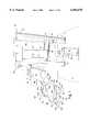
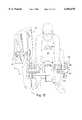
- FIG. 1is a side perspective view of an arm curl apparatus according to the present invention
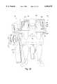
- FIG. 2is a side view of view the arm curl apparatus of FIG. 1 showing the support for the four bar linkage mechanisms;
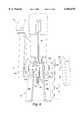
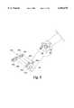
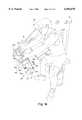
- FIG. 3is an enlarged view of a portion of the arm curl apparatus of FIG. 1 showing the cam assembly
- FIG. 4is an enlarged view of portion of the arm curl apparatus of FIG. 1 showing the cam assembly
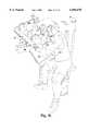
- FIG. 5is an expanded view of a four-bar linkage mechanism of the arm curl apparatus of FIG. 1;
- FIG. 6is an enlarged view of a portion of the arm curl apparatus of FIG. 1 showing he rotation of the cam assembly;
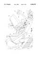
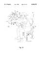
- FIG. 7is an expanded view of the arm curl apparatus of FIG. 1;
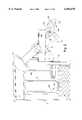
- FIG. 8is an illustration of a user in a starting position engaging the arm curl apparatus of FIG. 1 with a parallel grip
- FIG. 9is an illustration of a user in a starting position engaging the arm curl apparatus of FIG. 1 with a rotated over grip
- FIG. 10is an illustration of a user in a starting position engaging the arm curl apparatus of FIG. 1 with a horizontal over grip;
- FIG. 11is an illustration of a user in a starting position engaging the arm curl apparatus of FIG. 1 with a rotated under grip;
- FIG. 12is an illustration of a user in a starting position engaging the arm curl apparatus of FIG. 1 with a horizontal under grip;
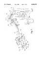
- FIG. 13is an illustration of a user in an active position engaging the arm curl apparatus of FIG. 1 with a rotated under grip;
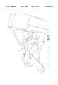
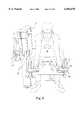
- FIG. 14is a perspective view of a user in a starting position showing the direction of movement of the four-bar linkages
- FIG. 15a perspective view of a user in an active position showing the direction of movement of the four-bar linkages.
- FIG. 16is a perspective view of a user in an active position showing the direction of movement of the four-bar linkages.
- Arm curl exercise machine 10preferably includes a selectable weight stack 12 operatively connected to each of a pair of four bar linkages 14a, 14b, a pair of handles 16a, 16b rotationally connected to the four-bar linkages 14a, 14b, respectively, a support 18 for supporting the pair of four-bar linkages 14a, b, a seat 20, a chest support 210 and an arm rest 23.
- the selectable weight mechanism 12is preferably a high-mass, short-travel (HMST) weight stack.
- HMST weight stackprovides the user with a higher mass weight stack and a shorter range of travel than conventional weight stacks.
- the speed of the selected weightdecreases during use without slowing down the speed of the user as he or she exercises, as described hereinbelow.
- the speed of the weightdecreases, so also does the negative inertial effect, allowing a user to train at higher contractal velocities without the associated negative inertial effect associated with conventional selectable weights, as described above. Overcoming the negative inertial effect, in turn, results in a smoother and more predictable resistance through the complete range of motion.
- the selectable weight mechanism 12is preferably disposed in an off-center position relative to the exercise ready, seating position of the user, such that the user can readily access and manually select or adjust the degree of weight force from a seated, exercise ready position.
- the selectable weight mechanism 12stands approximately 35 inches in height and preferably includes a housing 22 and a plurality of selectable weight plates 24 supported therein.
- the housing 22preferably supports the support 18 and is connected to seat 20 by brace 22b (FIG. 7).
- the total number of selectable weight plates 24 supported within the housing 22are referred to collectively as a "weight stack".
- the weight plates 24are each approximately 0.75 inches thick, and are uniform in weight at approximately 20 lbs. each. As shown in FIG.
- a top weight plate 28is operatively connected to a cable 30 and a central rod 32.
- the central rod 32extends in a downward direction from the top weight plate 28 through each of the consecutive weight plates 24.
- a pin 34is insertable through a transverse hole in each plate, and through the central rod to select or adjust the desired amount of weight for the exercise routine to be performed, as is known in the art.
- the weights 24are movable in first and second substantially vertical directions along guide rods 26a and 26b, respectively, as will be described in greater detail hereinbelow.
- the selectable weight plates 24preferably have a total mass of 300 lbs, which is twice the conventional mass (150 lbs) utilized with an arm curl machine.
- the selected weight plates 24travel at approximately half the speed of a selected weight plate of a conventional arm curl machine. Therefore, the selected weight is also subjected to approximately half the acceleration over approximately half the distance of a conventional selected weight plate utilized with a conventional arm curl machine.
- the distance "W” that the selected weight plates travelis approximately 43% of the distance "DC” traveled by a user's hand, in the present embodiment, as measured by the distance between the vertical positions of handles 16a and 16b at the start and stop of the exercise.
- the distance "DC"is a function of the length of the user's arm.
- the distance a user's hand travels from the beginning to the end of one repetition of the exercisedefines a complete range of motion.
- the massis doubled, the total load the user feels during the performance of an exercise routine is the same as with a conventional arm curl machine.
- this effectis achieved by changing the mechanical advantage to increase the leverage the user has over the selected weight plates from 1.15:1 (force exerted by user:weight) in a conventional system, to an approximately 2.3:1 ratio for the present system.
- Such increase in leverage ratiois preferably over about 1.5:1, and is typically from 2:1 to 4:1.
- the ratiois changed by attaching cable 30 through a reducer cam assembly 19 (FIG. 3) in the present embodiment, as described herein below.
- the leverage ratiomay be changed by attaching the cable 30 in other manners, as determined by conventional engineering techniques.
- Cam assembly 19(FIGS. 3 and 4) is utilized to provide the user with the necessary mechanical advantage, i.e. leverage, as described above.
- cam assembly 19is approximately 50% reduced in size from a conventional arm-curl cam assembly, and is mounted about rotational axle 31 which defines axis "x".
- Cam assembly 19is operatively connected to an input arm 21, which is, in turn, operatively connected by axle 25 (FIG. 7) to four bar linkages 14a, 14b, as described herein below.
- Cam assembly 19is also operatively connected to counter balance 39.
- cam assembly 19is secured to support 18 by a pair of bearing supports 27a, b, and preferably includes a groove 26 disposed in cam component 500 for receipt of cable 30.
- the cam component 500is fixedly attached to axle 31, which is rotatably mounted in supports 27a, 27b so as to allow for rotation of axle 31 around axis "x", the axle 31 being mounted by flange 34a to counter balance 39 at one end and is mounted by mounting flange 34b to input arm 21 at a second, opposite end and includes the operative components of cam assembly 19 mounted therebetween.
- cam component 500rotates and cable 30 in turn travels within groove 26 and around pulleys 61a-c, thus raising or lowering the selected weights.
- cam assembly 19is only one method to achieve the desired leverage, other equivalent methods will be readily known to one of skill in the art.
- the desired leverageis in turn dependant upon the percentage increase in the mass of the weights, the criteria being that the user should not feel the increase in mass from a conventional machine while exercising.
- the increase in massis, in turn, determined by several considerations, such as cost, structural load placed on the apparatus by the mass, as well as the ability to readily achieve the desired leverage for a given mass.
- support 18is preferably constructed of a rigid material, such as steel, and includes a pair of post members 18a, 18b, and a support arm 18c, of which combine to form the structural elements of support 18.
- Post members 18a, 18bare each secured to frame 22 of weight mechanism 12 and extend in a substantially perpendicular with respect thereto.
- Support arm 18cextends substantially perpendicular from post member 18b, adjacent input arm 21, and operates to support armrest 23. It will be understood to one of skill in the art that any number of structural elements, having a variety of shapes, sizes and orientations, may be utilized to form support 18, as long as the structural orientation supports the four bar linkages.
- seat 20includes a seat cushion 29 supported by a support 310, and is preferably adjustable between a plurality of positions.
- adjustment of seat 20is preferably enabled through a four-bar, gas-assist seat adjustment 35, although other methods of adjustment, for example hydraulic, may be utilized.
- a pin 33is insertable through each of a plurality of holes, in order to select the desired height of the seat.
- seat 20may be designed in a variety of configurations and dimensions, and may, or may not be adjustable.
- chest support 210Preferably located adjacent seat 20 and spaced therefrom is chest support 210. Chest support 21 engages and supports the chest of a user in the forward facing direction, as shown in FIGS. 15 and 16.
- bar linkages 14a, 14bare mounted at opposite ends to axle 25, and are operatively associated with the selectable weight stack 12, as will be described in greater detail herein below.
- Four bar linkages 14a, 14bare symmetrical in construction, therefore, the below detailed description of linkage 14a is applicable to symmetrical linkage 14b as well.
- Four bar linkage 14a, having a length "L" (FIG. 16)preferably includes primary lever arm 36a, a follower lever arm 38a, a handle lever arm 40a and a support plate 42a.
- Primary lever arm 36ais pivotally connected at a first end to a first portion 39a of handle lever arm 40a between handle lever arm extensions 63a and 64a, by pin 44a, and is pivotally connected at a second end, opposite the first end, between support plates 42a and 43a, by pin 46a.
- follower lever arm 38ais likewise pivotally connected at one end to the first portion 39a of handle lever arm 40a, between handle lever arm extensions 63a and 64a, by pin 48a, and is pivotally connected at a second end, opposite the first end, between support plates 42a and 43a, by pin 50a.
- follower lever arm 38ais preferably parallel to primary lever arm 36a.
- axle 25is preferably disposed parallel to a horizontal plane "A" underlying machine 10 (FIG. 1).
- handle lever arm 40apreferably includes a first portion 39a pivotally connected to the primary and follower lever arms 36a and 38a, and a second portion 41a extending inwardly at substantially a right angle from the first portion 39a.
- Handle 16ais preferably "U" shaped and is preferably pivotally or rotatably connected to the second portion 41a of handle lever arm 40a.
- handle 16ais pivotally or rotatably connected to handle lever arm 40a, by pin 53a (FIG. 8), although other sizes and attachment methods may be utilized provided, however, that handle 16a can pivot approximately 180-360 degrees about pin 53a with respect to handle lever arm 40a as shown in FIGS. 8-16.
- Handle 16ais also preferably covered with foam for user comfort.
- pulley system 56preferably includes a cable 30 attached at a first end to central rod 32 and is attached at a second end to cam 500.
- cable 30is routed from central rod 32, through a plurality of secondary pulleys 61a, b, c, respectively and through cam 500, where it is received within , groove or slot 26 of a cam member 500 and secured thereto, as described above.
- a userwill begin from a starting position, as shown in FIG. 14, and pull handles 16a, b, an upward direction, indicated by arrow "E". As the handles are pulled on, as shown in FIG.
- both primary lever arms 36a ,boperate to move axle 25 and hence input arm 21 and cam 500 to put cable 30 in a state of tension, which in turn puts tension on central rod 32, as described above.
- the tension on central rod 32is sufficient to move the rod in the direction of arrow "H" (FIG. 7), from an initial, at rest position, to a second, active position, against the force of the selected weights.
- a userPrior to performance of an exercise routine, a user will first adjust seat 20 to a desired position in which the user's feet will preferably be in contact with floor A. The user then selects the desired weight for performance of the exercise by inserting pin 34 into the transverse hole of the appropriate weight plate, as described above. Due to the off-center orientation of weight mechanism 12 with respect to seat 20, the user may select the weight from either a seated or a standing position. In either case, after the weight has been selected the user should be seated in seat 20 with the user's chest preferably resting against chest support 21. The direction the user is facing is considered the forward facing direction for purposes of this invention.
- Arm rest 23provides support to the user's arms during performance of the exercise routine. The user will then grasp the "U" shape handles with either hand. Once the user has grasped the handles 16a, 16b, the user is ready to perform a an arm curl exercise.
- the userperforms the arm curl exercise by first pulling on handles 16a, 16b in a tilted upward direction as indicated by arrow "E" (FIG. 14 and 15).
- the bottom end 41a of handle lever arm 40abegins to rotate slightly in the direction of arrow "Y”, which results in a slight tilt of handles 16a, b through the range of motion of the exercise.
- This slight tiltis enabled by the four-bar linkage mechanisms 14a, b in order to maintain proper biomechanical alignment of the user's wrist and forearm during performance of the exercise, regardless of the grip.
- Properor “correct biomechanical positioning,” as used herein, means that the orientation of the user's wrist and forearm may remain relatively constant from the start to finish of an arm curl exercise motion, i.e., throughout a complete range of motion. This may also mean that it is not necessary for the user to adjust their hand position on the handles while exercising.
- handles 16a, bmay choose to rotate handles 16a, 16b, clockwise or counterclockwise, as shown in FIGS. 8-16 and described above. This movement allows a user to exercise a wide variety of muscle groups associated with the hands and arms.
- Four bar linkages 14a, b and rotatable handles, 16a, benable as natural a human musculoskeletal upward pulling motion as possible while maintaining proper biomechanical alignment of the user's joints in an arm-curl exercise.
- cable 30is placed in a state of tension by cam component 500 which operates to move the selected weights vertically, in an upward direction within housing 22.
- cam component 500which operates to move the selected weights vertically, in an upward direction within housing 22.
- the userallows handles 16a, b to return to the starting position for the exercise.
- the selected weightsare moving in a vertical, downward direction, within housing 22. Once the user reaches the starting point of the exercise, one repetition has been completed through the range of motion of the user.
Landscapes
- Health & Medical Sciences (AREA)
- Orthopedic Medicine & Surgery (AREA)
- General Health & Medical Sciences (AREA)
- Physical Education & Sports Medicine (AREA)
- Life Sciences & Earth Sciences (AREA)
- Biophysics (AREA)
- Rehabilitation Tools (AREA)
Abstract
Description
Claims (11)
Priority Applications (1)
| Application Number | Priority Date | Filing Date | Title |
|---|---|---|---|
| US08/940,894US6056678A (en) | 1996-09-30 | 1997-09-30 | Arm curl apparatus for exercising regions of the upper body |
Applications Claiming Priority (2)
| Application Number | Priority Date | Filing Date | Title |
|---|---|---|---|
| US2705496P | 1996-09-30 | 1996-09-30 | |
| US08/940,894US6056678A (en) | 1996-09-30 | 1997-09-30 | Arm curl apparatus for exercising regions of the upper body |
Publications (1)
| Publication Number | Publication Date |
|---|---|
| US6056678Atrue US6056678A (en) | 2000-05-02 |
Family
ID=26701981
Family Applications (1)
| Application Number | Title | Priority Date | Filing Date |
|---|---|---|---|
| US08/940,894Expired - Fee RelatedUS6056678A (en) | 1996-09-30 | 1997-09-30 | Arm curl apparatus for exercising regions of the upper body |
Country Status (1)
| Country | Link |
|---|---|
| US (1) | US6056678A (en) |
Cited By (61)
| Publication number | Priority date | Publication date | Assignee | Title |
|---|---|---|---|---|
| US20020058572A1 (en)* | 2000-09-10 | 2002-05-16 | Kazuki Karasawa | Biceps curl machine |
| US6500106B1 (en)* | 1996-06-21 | 2002-12-31 | Kent Fulks | Method and apparatus for mechanical emulation of dumbbells |
| US20030134723A1 (en)* | 2002-01-17 | 2003-07-17 | Darrell Greenland | Exercise device |
| US20030166439A1 (en)* | 2002-03-04 | 2003-09-04 | Raymond Giannelli | Rowing machine |
| USD480773S1 (en) | 2002-11-13 | 2003-10-14 | Cybex International, Inc. | Weight stack support frame |
| USD490127S1 (en) | 2002-11-13 | 2004-05-18 | Cybex International, Inc. | Arm extension machine |
| DE10119466B4 (en)* | 2001-04-12 | 2004-07-08 | Heiko Fiebig | Strength training device for training the arm muscles with an adjustable load arm |
| US20050020416A1 (en)* | 2000-03-21 | 2005-01-27 | Strive Enterprises, Inc. | Weight training machine |
| EP1566204A3 (en)* | 2004-02-21 | 2005-09-21 | James Ryder Mason | Fitness apparatus |
| US20060128535A1 (en)* | 2004-12-13 | 2006-06-15 | Nautilus, Inc. | Arm assembly for exercise devices |
| US7070545B2 (en) | 2002-07-01 | 2006-07-04 | Nautilus, Inc. | Leg press and abdominal crunch exercise machine |
| US7070546B1 (en) | 2002-07-05 | 2006-07-04 | Joseph Grasso | Exercise apparatus including multiple function aspects and small footprint |
| US7083554B1 (en) | 1997-02-27 | 2006-08-01 | Nautilus, Inc. | Exercise machine with infinite position range limiter and automatic belt tensioning system |
| US7104934B1 (en) | 2005-04-08 | 2006-09-12 | John Patrick Smith | Hand exercise device |
| US7108641B2 (en) | 2000-05-03 | 2006-09-19 | Nautilus, Inc. | Exercise equipment with multi-positioning handles |
| US7115080B2 (en) | 2002-08-01 | 2006-10-03 | Nautilus, Inc. | Collapsible seat for combination hack squat and leg press machine |
| USD533910S1 (en) | 2005-03-15 | 2006-12-19 | Nautilus, Inc. | Exercise device |
| US20070042877A1 (en)* | 2003-05-15 | 2007-02-22 | Choi Yun-Seok | Apparatus for three-dimensional anaerobic exercise |
| US20080026920A1 (en)* | 2006-07-27 | 2008-01-31 | Annaniy Berenshteyn | Weightlifting apparatus for pronation and supination exercises |
| US20080058181A1 (en)* | 2006-09-06 | 2008-03-06 | Webber Randall T | Arm exercise machine with self-aligning pivoting user support |
| US20080085822A1 (en)* | 2006-10-04 | 2008-04-10 | Nautilus, Inc. | Dual axis abdominal exercise apparatus |
| US20090225627A1 (en)* | 2005-05-10 | 2009-09-10 | Schlumberger Technology Corporation | Use of an effective tool model in sonic logging data processing |
| US20100248912A1 (en)* | 2009-03-25 | 2010-09-30 | Gil Reyes | Isolated curl machine and method of training therefor |
| US7922635B2 (en) | 2000-03-10 | 2011-04-12 | Nautilus, Inc. | Adjustable-load unitary multi-position bench exercise unit |
| US7922630B1 (en)* | 2006-06-15 | 2011-04-12 | Roger Batca | Adjustable bicep curl support pads |
| US7938760B1 (en) | 2008-10-17 | 2011-05-10 | Hoist Fitness Systems, Inc. | Exercise machine with lifting arm |
| US7981010B1 (en) | 2003-08-04 | 2011-07-19 | Hoist Fitness Systems, Inc. | Exercise machine with multi-function user engagement device |
| US7993251B1 (en) | 2003-08-04 | 2011-08-09 | Hoist Fitness Systems, Inc. | Pectoral fly exercise machine |
| GB2477609A (en)* | 2010-02-05 | 2011-08-10 | Ze Jing Jhang | A counterweight arrangement with reduced friction between a plurality of weights and two guide rods |
| US20110207584A1 (en)* | 2010-02-25 | 2011-08-25 | Hoist Fitness Systems, Inc. | Calf Exercise Machine With Rocking User Support |
| US20110224058A1 (en)* | 2010-03-05 | 2011-09-15 | Hoist Fitness Systems, Inc. | Thigh exercise machine with rocking user support |
| US20110281697A1 (en)* | 2009-03-25 | 2011-11-17 | Gil Reyes | Isolated curl machine and method of training therefor |
| KR101197930B1 (en) | 2010-05-26 | 2012-11-05 | 서울대학교산학협력단 | Arm-curl fitness apparatus for developing diverse muscles by driven scapular movement |
| US8734304B2 (en) | 2010-03-04 | 2014-05-27 | Hoist Fitness Systems, Inc. | Low back exercise machine with rocking user support |
| CN106163482A (en)* | 2014-04-11 | 2016-11-23 | 韩国科学技术研究院 | Upper extremity strength strengthens servicing unit |
| JP2016220908A (en)* | 2015-05-29 | 2016-12-28 | 是吉興業株式会社 | Training equipment |
| US10188890B2 (en) | 2013-12-26 | 2019-01-29 | Icon Health & Fitness, Inc. | Magnetic resistance mechanism in a cable machine |
| US10252109B2 (en) | 2016-05-13 | 2019-04-09 | Icon Health & Fitness, Inc. | Weight platform treadmill |
| US10258828B2 (en) | 2015-01-16 | 2019-04-16 | Icon Health & Fitness, Inc. | Controls for an exercise device |
| US10272317B2 (en) | 2016-03-18 | 2019-04-30 | Icon Health & Fitness, Inc. | Lighted pace feature in a treadmill |
| US10279212B2 (en) | 2013-03-14 | 2019-05-07 | Icon Health & Fitness, Inc. | Strength training apparatus with flywheel and related methods |
| US10293211B2 (en) | 2016-03-18 | 2019-05-21 | Icon Health & Fitness, Inc. | Coordinated weight selection |
| US10343017B2 (en) | 2016-11-01 | 2019-07-09 | Icon Health & Fitness, Inc. | Distance sensor for console positioning |
| US10376736B2 (en) | 2016-10-12 | 2019-08-13 | Icon Health & Fitness, Inc. | Cooling an exercise device during a dive motor runway condition |
| US10426989B2 (en) | 2014-06-09 | 2019-10-01 | Icon Health & Fitness, Inc. | Cable system incorporated into a treadmill |
| US10433612B2 (en) | 2014-03-10 | 2019-10-08 | Icon Health & Fitness, Inc. | Pressure sensor to quantify work |
| US10441844B2 (en) | 2016-07-01 | 2019-10-15 | Icon Health & Fitness, Inc. | Cooling systems and methods for exercise equipment |
| US10441840B2 (en) | 2016-03-18 | 2019-10-15 | Icon Health & Fitness, Inc. | Collapsible strength exercise machine |
| US10449416B2 (en) | 2015-08-26 | 2019-10-22 | Icon Health & Fitness, Inc. | Strength exercise mechanisms |
| US10471299B2 (en) | 2016-07-01 | 2019-11-12 | Icon Health & Fitness, Inc. | Systems and methods for cooling internal exercise equipment components |
| US10493349B2 (en) | 2016-03-18 | 2019-12-03 | Icon Health & Fitness, Inc. | Display on exercise device |
| US10500473B2 (en) | 2016-10-10 | 2019-12-10 | Icon Health & Fitness, Inc. | Console positioning |
| US10543395B2 (en) | 2016-12-05 | 2020-01-28 | Icon Health & Fitness, Inc. | Offsetting treadmill deck weight during operation |
| US10561894B2 (en) | 2016-03-18 | 2020-02-18 | Icon Health & Fitness, Inc. | Treadmill with removable supports |
| US10625114B2 (en) | 2016-11-01 | 2020-04-21 | Icon Health & Fitness, Inc. | Elliptical and stationary bicycle apparatus including row functionality |
| US10625137B2 (en) | 2016-03-18 | 2020-04-21 | Icon Health & Fitness, Inc. | Coordinated displays in an exercise device |
| US10661114B2 (en) | 2016-11-01 | 2020-05-26 | Icon Health & Fitness, Inc. | Body weight lift mechanism on treadmill |
| US10729965B2 (en) | 2017-12-22 | 2020-08-04 | Icon Health & Fitness, Inc. | Audible belt guide in a treadmill |
| US10940360B2 (en) | 2015-08-26 | 2021-03-09 | Icon Health & Fitness, Inc. | Strength exercise mechanisms |
| US10953305B2 (en) | 2015-08-26 | 2021-03-23 | Icon Health & Fitness, Inc. | Strength exercise mechanisms |
| US11451108B2 (en) | 2017-08-16 | 2022-09-20 | Ifit Inc. | Systems and methods for axial impact resistance in electric motors |
Citations (5)
| Publication number | Priority date | Publication date | Assignee | Title |
|---|---|---|---|---|
| US4411424A (en)* | 1982-02-08 | 1983-10-25 | Barnett Robert V | Weight lifting exercise apparatus |
| US4563003A (en)* | 1983-04-15 | 1986-01-07 | Fernando Bugallo | Weight lifting apparatus having increased force on the return stroke |
| US5116297A (en)* | 1991-03-04 | 1992-05-26 | Stonecipher William L | Weight-lifting machine |
| US5437589A (en)* | 1993-12-20 | 1995-08-01 | Habing; Theodore J. | Upper body exercise machine |
| US5562577A (en)* | 1994-02-07 | 1996-10-08 | Southern Xercise, Inc. | Upper torso exercise apparatus |
- 1997
- 1997-09-30USUS08/940,894patent/US6056678A/ennot_activeExpired - Fee Related
Patent Citations (5)
| Publication number | Priority date | Publication date | Assignee | Title |
|---|---|---|---|---|
| US4411424A (en)* | 1982-02-08 | 1983-10-25 | Barnett Robert V | Weight lifting exercise apparatus |
| US4563003A (en)* | 1983-04-15 | 1986-01-07 | Fernando Bugallo | Weight lifting apparatus having increased force on the return stroke |
| US5116297A (en)* | 1991-03-04 | 1992-05-26 | Stonecipher William L | Weight-lifting machine |
| US5437589A (en)* | 1993-12-20 | 1995-08-01 | Habing; Theodore J. | Upper body exercise machine |
| US5562577A (en)* | 1994-02-07 | 1996-10-08 | Southern Xercise, Inc. | Upper torso exercise apparatus |
Non-Patent Citations (2)
| Title |
|---|
| "Swivel Grip" Brochure, Copy in 482/139, 1994. |
| Swivel Grip Brochure, Copy in 482/139, 1994.* |
Cited By (85)
| Publication number | Priority date | Publication date | Assignee | Title |
|---|---|---|---|---|
| US6500106B1 (en)* | 1996-06-21 | 2002-12-31 | Kent Fulks | Method and apparatus for mechanical emulation of dumbbells |
| US7083554B1 (en) | 1997-02-27 | 2006-08-01 | Nautilus, Inc. | Exercise machine with infinite position range limiter and automatic belt tensioning system |
| US7922635B2 (en) | 2000-03-10 | 2011-04-12 | Nautilus, Inc. | Adjustable-load unitary multi-position bench exercise unit |
| US20050020416A1 (en)* | 2000-03-21 | 2005-01-27 | Strive Enterprises, Inc. | Weight training machine |
| US7608028B2 (en) | 2000-05-03 | 2009-10-27 | Nautilus, Inc. | Exercise equipment with multi-positioning handles |
| US7108641B2 (en) | 2000-05-03 | 2006-09-19 | Nautilus, Inc. | Exercise equipment with multi-positioning handles |
| US20020058572A1 (en)* | 2000-09-10 | 2002-05-16 | Kazuki Karasawa | Biceps curl machine |
| DE10119466B4 (en)* | 2001-04-12 | 2004-07-08 | Heiko Fiebig | Strength training device for training the arm muscles with an adjustable load arm |
| US6913565B2 (en)* | 2001-06-20 | 2005-07-05 | Nautilus Human Performance Systems, Inc. | Biceps curl machine |
| US6905446B2 (en) | 2002-01-17 | 2005-06-14 | Darrell Greenland | Exercise device |
| US20050209070A1 (en)* | 2002-01-17 | 2005-09-22 | Darrell Greenland | Exercise device |
| US20030134723A1 (en)* | 2002-01-17 | 2003-07-17 | Darrell Greenland | Exercise device |
| US8944969B2 (en) | 2002-03-04 | 2015-02-03 | Cybex International, Inc. | Rowing machine |
| US20030166439A1 (en)* | 2002-03-04 | 2003-09-04 | Raymond Giannelli | Rowing machine |
| US7608022B2 (en) | 2002-07-01 | 2009-10-27 | Nautilus, Inc. | Leg press and abdominal crunch exercise machine |
| US7070545B2 (en) | 2002-07-01 | 2006-07-04 | Nautilus, Inc. | Leg press and abdominal crunch exercise machine |
| US7070546B1 (en) | 2002-07-05 | 2006-07-04 | Joseph Grasso | Exercise apparatus including multiple function aspects and small footprint |
| US7115080B2 (en) | 2002-08-01 | 2006-10-03 | Nautilus, Inc. | Collapsible seat for combination hack squat and leg press machine |
| USD490127S1 (en) | 2002-11-13 | 2004-05-18 | Cybex International, Inc. | Arm extension machine |
| USD480773S1 (en) | 2002-11-13 | 2003-10-14 | Cybex International, Inc. | Weight stack support frame |
| US20070042877A1 (en)* | 2003-05-15 | 2007-02-22 | Choi Yun-Seok | Apparatus for three-dimensional anaerobic exercise |
| US7993251B1 (en) | 2003-08-04 | 2011-08-09 | Hoist Fitness Systems, Inc. | Pectoral fly exercise machine |
| US7981010B1 (en) | 2003-08-04 | 2011-07-19 | Hoist Fitness Systems, Inc. | Exercise machine with multi-function user engagement device |
| EP1566204A3 (en)* | 2004-02-21 | 2005-09-21 | James Ryder Mason | Fitness apparatus |
| US7775945B2 (en) | 2004-12-13 | 2010-08-17 | Nautilus, Inc. | Arm assembly for exercise devices |
| US20060128535A1 (en)* | 2004-12-13 | 2006-06-15 | Nautilus, Inc. | Arm assembly for exercise devices |
| USD566798S1 (en) | 2005-03-15 | 2008-04-15 | Nautilus, Inc. | Exercise device |
| USD550789S1 (en) | 2005-03-15 | 2007-09-11 | Nautilus, Inc. | Exercise device |
| USD533910S1 (en) | 2005-03-15 | 2006-12-19 | Nautilus, Inc. | Exercise device |
| US7104934B1 (en) | 2005-04-08 | 2006-09-12 | John Patrick Smith | Hand exercise device |
| US20090225627A1 (en)* | 2005-05-10 | 2009-09-10 | Schlumberger Technology Corporation | Use of an effective tool model in sonic logging data processing |
| US7922630B1 (en)* | 2006-06-15 | 2011-04-12 | Roger Batca | Adjustable bicep curl support pads |
| US20080026920A1 (en)* | 2006-07-27 | 2008-01-31 | Annaniy Berenshteyn | Weightlifting apparatus for pronation and supination exercises |
| US20100016128A1 (en)* | 2006-09-06 | 2010-01-21 | Hoist Fitness Systems, Inc. | Arm Exercise Machine With Self-Aligning Pivoting User Support |
| US20080058181A1 (en)* | 2006-09-06 | 2008-03-06 | Webber Randall T | Arm exercise machine with self-aligning pivoting user support |
| US7901337B2 (en)* | 2006-09-06 | 2011-03-08 | Hoist Fitness Systems, Inc. | Arm exercise machine with self-aligning pivoting user support |
| US7654940B2 (en) | 2006-09-06 | 2010-02-02 | Hoist Fitness Systems, Inc. | Arm exercise machine with self-aligning pivoting user support |
| US20080085822A1 (en)* | 2006-10-04 | 2008-04-10 | Nautilus, Inc. | Dual axis abdominal exercise apparatus |
| US7658701B2 (en) | 2006-10-04 | 2010-02-09 | Nautilus, Inc. | Dual axis abdominal exercise apparatus |
| US10646739B2 (en) | 2008-10-17 | 2020-05-12 | Hoist Fitness Systems, Inc. | Exercise machine with lifting arm |
| US11759668B2 (en) | 2008-10-17 | 2023-09-19 | Hoist Fitness Systems, Inc. | Exercise machine with lifting arm |
| US11000722B2 (en) | 2008-10-17 | 2021-05-11 | Hoist Fitness Systems, Inc. | Exercise machine with lifting arm |
| US7938760B1 (en) | 2008-10-17 | 2011-05-10 | Hoist Fitness Systems, Inc. | Exercise machine with lifting arm |
| US10639513B2 (en) | 2008-10-17 | 2020-05-05 | Hoist Fitness Systems, Inc. | Exercise machine with lifting arm |
| US9861850B1 (en) | 2008-10-17 | 2018-01-09 | Hoist Fitness Systems, Inc. | Exercise machine with lifting arm |
| US7959543B2 (en)* | 2009-03-25 | 2011-06-14 | Graa Innovations, Llc | Isolated curl machine and method of training therefor |
| WO2010110889A3 (en)* | 2009-03-25 | 2011-01-13 | Graa Innovations, Llc | Isolated curl machine and method of training therefor |
| US20100248912A1 (en)* | 2009-03-25 | 2010-09-30 | Gil Reyes | Isolated curl machine and method of training therefor |
| US20110281697A1 (en)* | 2009-03-25 | 2011-11-17 | Gil Reyes | Isolated curl machine and method of training therefor |
| CN102413880A (en)* | 2009-03-25 | 2012-04-11 | 格拉创新有限责任公司 | Independent curling equipment and its training method |
| US9050497B2 (en)* | 2009-03-25 | 2015-06-09 | Graa Innovations, Llc | Isolated curl machine and method of training therefor |
| GB2477609A (en)* | 2010-02-05 | 2011-08-10 | Ze Jing Jhang | A counterweight arrangement with reduced friction between a plurality of weights and two guide rods |
| US20110207584A1 (en)* | 2010-02-25 | 2011-08-25 | Hoist Fitness Systems, Inc. | Calf Exercise Machine With Rocking User Support |
| US8177693B2 (en) | 2010-02-25 | 2012-05-15 | Hoist Fitness Systems, Inc. | Calf exercise machine with rocking user support |
| US8734304B2 (en) | 2010-03-04 | 2014-05-27 | Hoist Fitness Systems, Inc. | Low back exercise machine with rocking user support |
| US20110224058A1 (en)* | 2010-03-05 | 2011-09-15 | Hoist Fitness Systems, Inc. | Thigh exercise machine with rocking user support |
| US8562496B2 (en) | 2010-03-05 | 2013-10-22 | Hoist Fitness Systems, Inc. | Thigh exercise machine with rocking user support |
| KR101197930B1 (en) | 2010-05-26 | 2012-11-05 | 서울대학교산학협력단 | Arm-curl fitness apparatus for developing diverse muscles by driven scapular movement |
| US10279212B2 (en) | 2013-03-14 | 2019-05-07 | Icon Health & Fitness, Inc. | Strength training apparatus with flywheel and related methods |
| US10188890B2 (en) | 2013-12-26 | 2019-01-29 | Icon Health & Fitness, Inc. | Magnetic resistance mechanism in a cable machine |
| US10433612B2 (en) | 2014-03-10 | 2019-10-08 | Icon Health & Fitness, Inc. | Pressure sensor to quantify work |
| CN106163482A (en)* | 2014-04-11 | 2016-11-23 | 韩国科学技术研究院 | Upper extremity strength strengthens servicing unit |
| US10426989B2 (en) | 2014-06-09 | 2019-10-01 | Icon Health & Fitness, Inc. | Cable system incorporated into a treadmill |
| US10258828B2 (en) | 2015-01-16 | 2019-04-16 | Icon Health & Fitness, Inc. | Controls for an exercise device |
| JP2016220908A (en)* | 2015-05-29 | 2016-12-28 | 是吉興業株式会社 | Training equipment |
| US10449416B2 (en) | 2015-08-26 | 2019-10-22 | Icon Health & Fitness, Inc. | Strength exercise mechanisms |
| US10940360B2 (en) | 2015-08-26 | 2021-03-09 | Icon Health & Fitness, Inc. | Strength exercise mechanisms |
| US10953305B2 (en) | 2015-08-26 | 2021-03-23 | Icon Health & Fitness, Inc. | Strength exercise mechanisms |
| US10441840B2 (en) | 2016-03-18 | 2019-10-15 | Icon Health & Fitness, Inc. | Collapsible strength exercise machine |
| US10625137B2 (en) | 2016-03-18 | 2020-04-21 | Icon Health & Fitness, Inc. | Coordinated displays in an exercise device |
| US10493349B2 (en) | 2016-03-18 | 2019-12-03 | Icon Health & Fitness, Inc. | Display on exercise device |
| US10561894B2 (en) | 2016-03-18 | 2020-02-18 | Icon Health & Fitness, Inc. | Treadmill with removable supports |
| US10293211B2 (en) | 2016-03-18 | 2019-05-21 | Icon Health & Fitness, Inc. | Coordinated weight selection |
| US10272317B2 (en) | 2016-03-18 | 2019-04-30 | Icon Health & Fitness, Inc. | Lighted pace feature in a treadmill |
| US10252109B2 (en) | 2016-05-13 | 2019-04-09 | Icon Health & Fitness, Inc. | Weight platform treadmill |
| US10441844B2 (en) | 2016-07-01 | 2019-10-15 | Icon Health & Fitness, Inc. | Cooling systems and methods for exercise equipment |
| US10471299B2 (en) | 2016-07-01 | 2019-11-12 | Icon Health & Fitness, Inc. | Systems and methods for cooling internal exercise equipment components |
| US10500473B2 (en) | 2016-10-10 | 2019-12-10 | Icon Health & Fitness, Inc. | Console positioning |
| US10376736B2 (en) | 2016-10-12 | 2019-08-13 | Icon Health & Fitness, Inc. | Cooling an exercise device during a dive motor runway condition |
| US10661114B2 (en) | 2016-11-01 | 2020-05-26 | Icon Health & Fitness, Inc. | Body weight lift mechanism on treadmill |
| US10625114B2 (en) | 2016-11-01 | 2020-04-21 | Icon Health & Fitness, Inc. | Elliptical and stationary bicycle apparatus including row functionality |
| US10343017B2 (en) | 2016-11-01 | 2019-07-09 | Icon Health & Fitness, Inc. | Distance sensor for console positioning |
| US10543395B2 (en) | 2016-12-05 | 2020-01-28 | Icon Health & Fitness, Inc. | Offsetting treadmill deck weight during operation |
| US11451108B2 (en) | 2017-08-16 | 2022-09-20 | Ifit Inc. | Systems and methods for axial impact resistance in electric motors |
| US10729965B2 (en) | 2017-12-22 | 2020-08-04 | Icon Health & Fitness, Inc. | Audible belt guide in a treadmill |
Similar Documents
| Publication | Publication Date | Title |
|---|---|---|
| US6056678A (en) | Arm curl apparatus for exercising regions of the upper body | |
| US6254516B1 (en) | Shoulder press apparatus for exercising regions of the upper body | |
| US5989165A (en) | Incline press apparatus for exercising regions of the upper body | |
| US6071216A (en) | Pull down apparatus for exercising regions of the upper body | |
| US5997447A (en) | Chest press apparatus for exercising regions of the upper body | |
| US5413546A (en) | Bicep exercise device | |
| US7052446B2 (en) | Lat pulldown weight training machine | |
| US5711749A (en) | Trunk strengthening cardiovascular exercise apparatus | |
| US5573485A (en) | Exercising and stretching apparatus | |
| US6830542B2 (en) | Rowing weight training machine | |
| US5370594A (en) | Adjustable and configurable exercise machine | |
| US5429569A (en) | Training apparatus | |
| US6080091A (en) | Exercise machine press arm | |
| EP1276543B1 (en) | Exercise apparatus | |
| US6004247A (en) | Exercise apparatus with multi-exercise press station | |
| US6394936B1 (en) | Convergent exercise machine and method | |
| US7641596B2 (en) | Golf swing simulator and exercise device | |
| US6913565B2 (en) | Biceps curl machine | |
| US7641595B2 (en) | Golf exercise device | |
| US5971896A (en) | Shoulder press apparatus for exercising regions of the upper body | |
| US7294096B1 (en) | Torso exercise methods and apparatus | |
| US6770017B1 (en) | Weight training machine | |
| US6910994B2 (en) | Triceps extension machine | |
| US7666123B2 (en) | Upper torso exercise machine | |
| US20030092543A1 (en) | Upper torso exercise machine |
Legal Events
| Date | Code | Title | Description |
|---|---|---|---|
| AS | Assignment | Owner name:CYBEX INTERNATIONAL, INC., MASSACHUSETTS Free format text:ASSIGNMENT OF ASSIGNORS INTEREST;ASSIGNORS:GIANNELLI, RAYMOND;LEIPHEIMER, JERRY K.;REEL/FRAME:009190/0123;SIGNING DATES FROM 19190422 TO 19980504 | |
| FEPP | Fee payment procedure | Free format text:PAYOR NUMBER ASSIGNED (ORIGINAL EVENT CODE: ASPN); ENTITY STATUS OF PATENT OWNER: LARGE ENTITY | |
| FEPP | Fee payment procedure | Free format text:PAYOR NUMBER ASSIGNED (ORIGINAL EVENT CODE: ASPN); ENTITY STATUS OF PATENT OWNER: LARGE ENTITY Free format text:PAYER NUMBER DE-ASSIGNED (ORIGINAL EVENT CODE: RMPN); ENTITY STATUS OF PATENT OWNER: LARGE ENTITY | |
| FEPP | Fee payment procedure | Free format text:PAYOR NUMBER ASSIGNED (ORIGINAL EVENT CODE: ASPN); ENTITY STATUS OF PATENT OWNER: LARGE ENTITY Free format text:PAYER NUMBER DE-ASSIGNED (ORIGINAL EVENT CODE: RMPN); ENTITY STATUS OF PATENT OWNER: LARGE ENTITY | |
| AS | Assignment | Owner name:HILCO CAPITAL LLP, ILLINOIS Free format text:SECURITY INTEREST;ASSIGNOR:CYBEX INTERNATIONAL, INC.;REEL/FRAME:013879/0826 Effective date:20030716 | |
| AS | Assignment | Owner name:CIT GROUP/BUSINESS CREDIT, INC., THE, NORTH CAROLI Free format text:NOTICE OF GRANT OF SECURITY INTEREST;ASSIGNOR:CYBEX INTERNATIONAL, INC.;REEL/FRAME:013913/0712 Effective date:20030716 | |
| FPAY | Fee payment | Year of fee payment:4 | |
| AS | Assignment | Owner name:CYBEX INTERNATIONAL, INC., MASSACHUSETTS Free format text:RELEASE OF SECURITY INTEREST;ASSIGNOR:HILCO CAPITAL, LP;REEL/FRAME:016309/0328 Effective date:20040713 | |
| FPAY | Fee payment | Year of fee payment:8 | |
| CC | Certificate of correction | ||
| AS | Assignment | Owner name:CYBEX INTERNATIONAL, INC., MASSACHUSETTS Free format text:RELEASE BY SECURED PARTY;ASSIGNOR:CIT GROUP/BUSINESS CREDIT, INC.;REEL/FRAME:026046/0651 Effective date:20110328 | |
| REMI | Maintenance fee reminder mailed | ||
| LAPS | Lapse for failure to pay maintenance fees | ||
| STCH | Information on status: patent discontinuation | Free format text:PATENT EXPIRED DUE TO NONPAYMENT OF MAINTENANCE FEES UNDER 37 CFR 1.362 | |
| FP | Lapsed due to failure to pay maintenance fee | Effective date:20120502 |