US6056670A - Power controlled exercising machine and method for controlling the same - Google Patents
Power controlled exercising machine and method for controlling the sameDownload PDFInfo
- Publication number
- US6056670A US6056670AUS08/249,248US24924894AUS6056670AUS 6056670 AUS6056670 AUS 6056670AUS 24924894 AUS24924894 AUS 24924894AUS 6056670 AUS6056670 AUS 6056670A
- Authority
- US
- United States
- Prior art keywords
- exercise
- power
- load
- alternator
- user
- Prior art date
- Legal status (The legal status is an assumption and is not a legal conclusion. Google has not performed a legal analysis and makes no representation as to the accuracy of the status listed.)
- Expired - Lifetime
Links
- 238000000034methodMethods0.000titledescription11
- 230000002503metabolic effectEffects0.000claimsdescription14
- 230000004044responseEffects0.000claimsdescription4
- 230000036962time dependentEffects0.000claimsdescription3
- 230000008602contractionEffects0.000claims1
- 238000005265energy consumptionMethods0.000abstractdescription3
- 238000012544monitoring processMethods0.000abstractdescription2
- 230000001429stepping effectEffects0.000description12
- 230000033001locomotionEffects0.000description7
- 230000009194climbingEffects0.000description5
- 230000005540biological transmissionEffects0.000description4
- 210000002683footAnatomy0.000description4
- 230000006870functionEffects0.000description4
- 238000010586diagramMethods0.000description3
- 230000006872improvementEffects0.000description3
- 230000000977initiatory effectEffects0.000description3
- 238000012545processingMethods0.000description3
- 230000001131transforming effectEffects0.000description3
- 230000002493climbing effectEffects0.000description2
- 230000007246mechanismEffects0.000description2
- 230000029058respiratory gaseous exchangeEffects0.000description2
- 210000004243sweatAnatomy0.000description2
- 230000004075alterationEffects0.000description1
- 210000003423ankleAnatomy0.000description1
- 230000000712assemblyEffects0.000description1
- 238000000429assemblyMethods0.000description1
- 230000006399behaviorEffects0.000description1
- 244000309464bullSpecies0.000description1
- 238000010276constructionMethods0.000description1
- 125000004122cyclic groupChemical group0.000description1
- 238000001514detection methodMethods0.000description1
- 238000007599dischargingMethods0.000description1
- 238000009826distributionMethods0.000description1
- 210000003414extremityAnatomy0.000description1
- 230000036541healthEffects0.000description1
- 238000003780insertionMethods0.000description1
- 230000037431insertionEffects0.000description1
- 230000037323metabolic rateEffects0.000description1
- 238000012986modificationMethods0.000description1
- 230000004048modificationEffects0.000description1
- 210000003205muscleAnatomy0.000description1
- 230000035479physiological effects, processes and functionsEffects0.000description1
- 230000005855radiationEffects0.000description1
- 230000002459sustained effectEffects0.000description1
- 238000004804windingMethods0.000description1
Images

Classifications
- A—HUMAN NECESSITIES
- A63—SPORTS; GAMES; AMUSEMENTS
- A63B—APPARATUS FOR PHYSICAL TRAINING, GYMNASTICS, SWIMMING, CLIMBING, OR FENCING; BALL GAMES; TRAINING EQUIPMENT
- A63B22/00—Exercising apparatus specially adapted for conditioning the cardio-vascular system, for training agility or co-ordination of movements
- A63B22/0048—Exercising apparatus specially adapted for conditioning the cardio-vascular system, for training agility or co-ordination of movements with cantilevered support elements pivoting about an axis
- A63B22/0056—Exercising apparatus specially adapted for conditioning the cardio-vascular system, for training agility or co-ordination of movements with cantilevered support elements pivoting about an axis the pivoting movement being in a vertical plane, e.g. steppers with a horizontal axis
- A—HUMAN NECESSITIES
- A63—SPORTS; GAMES; AMUSEMENTS
- A63B—APPARATUS FOR PHYSICAL TRAINING, GYMNASTICS, SWIMMING, CLIMBING, OR FENCING; BALL GAMES; TRAINING EQUIPMENT
- A63B21/00—Exercising apparatus for developing or strengthening the muscles or joints of the body by working against a counterforce, with or without measuring devices
- A63B21/005—Exercising apparatus for developing or strengthening the muscles or joints of the body by working against a counterforce, with or without measuring devices using electromagnetic or electric force-resisters
- A63B21/0053—Exercising apparatus for developing or strengthening the muscles or joints of the body by working against a counterforce, with or without measuring devices using electromagnetic or electric force-resisters using alternators or dynamos
- A63B21/0054—Exercising apparatus for developing or strengthening the muscles or joints of the body by working against a counterforce, with or without measuring devices using electromagnetic or electric force-resisters using alternators or dynamos for charging a battery
- A—HUMAN NECESSITIES
- A63—SPORTS; GAMES; AMUSEMENTS
- A63B—APPARATUS FOR PHYSICAL TRAINING, GYMNASTICS, SWIMMING, CLIMBING, OR FENCING; BALL GAMES; TRAINING EQUIPMENT
- A63B69/00—Training appliances or apparatus for special sports
- A63B69/0057—Means for physically limiting movements of body parts
- A—HUMAN NECESSITIES
- A63—SPORTS; GAMES; AMUSEMENTS
- A63B—APPARATUS FOR PHYSICAL TRAINING, GYMNASTICS, SWIMMING, CLIMBING, OR FENCING; BALL GAMES; TRAINING EQUIPMENT
- A63B22/00—Exercising apparatus specially adapted for conditioning the cardio-vascular system, for training agility or co-ordination of movements
- A63B22/0025—Particular aspects relating to the orientation of movement paths of the limbs relative to the body; Relative relationship between the movements of the limbs
- A63B2022/0038—One foot moving independently from the other, i.e. there is no link between the movements of the feet
- A—HUMAN NECESSITIES
- A63—SPORTS; GAMES; AMUSEMENTS
- A63B—APPARATUS FOR PHYSICAL TRAINING, GYMNASTICS, SWIMMING, CLIMBING, OR FENCING; BALL GAMES; TRAINING EQUIPMENT
- A63B22/00—Exercising apparatus specially adapted for conditioning the cardio-vascular system, for training agility or co-ordination of movements
- A63B22/0048—Exercising apparatus specially adapted for conditioning the cardio-vascular system, for training agility or co-ordination of movements with cantilevered support elements pivoting about an axis
- A63B2022/0053—Exercising apparatus specially adapted for conditioning the cardio-vascular system, for training agility or co-ordination of movements with cantilevered support elements pivoting about an axis each support element being cantilevered by a parallelogram system
- A—HUMAN NECESSITIES
- A63—SPORTS; GAMES; AMUSEMENTS
- A63B—APPARATUS FOR PHYSICAL TRAINING, GYMNASTICS, SWIMMING, CLIMBING, OR FENCING; BALL GAMES; TRAINING EQUIPMENT
- A63B21/00—Exercising apparatus for developing or strengthening the muscles or joints of the body by working against a counterforce, with or without measuring devices
- A63B21/22—Resisting devices with rotary bodies
- A63B21/225—Resisting devices with rotary bodies with flywheels
- A—HUMAN NECESSITIES
- A63—SPORTS; GAMES; AMUSEMENTS
- A63B—APPARATUS FOR PHYSICAL TRAINING, GYMNASTICS, SWIMMING, CLIMBING, OR FENCING; BALL GAMES; TRAINING EQUIPMENT
- A63B2208/00—Characteristics or parameters related to the user or player
- A63B2208/02—Characteristics or parameters related to the user or player posture
- A63B2208/0204—Standing on the feet
- A—HUMAN NECESSITIES
- A63—SPORTS; GAMES; AMUSEMENTS
- A63B—APPARATUS FOR PHYSICAL TRAINING, GYMNASTICS, SWIMMING, CLIMBING, OR FENCING; BALL GAMES; TRAINING EQUIPMENT
- A63B2220/00—Measuring of physical parameters relating to sporting activity
- A63B2220/30—Speed
- A—HUMAN NECESSITIES
- A63—SPORTS; GAMES; AMUSEMENTS
- A63B—APPARATUS FOR PHYSICAL TRAINING, GYMNASTICS, SWIMMING, CLIMBING, OR FENCING; BALL GAMES; TRAINING EQUIPMENT
- A63B2220/00—Measuring of physical parameters relating to sporting activity
- A63B2220/30—Speed
- A63B2220/36—Speed measurement by electric or magnetic parameters
- Y—GENERAL TAGGING OF NEW TECHNOLOGICAL DEVELOPMENTS; GENERAL TAGGING OF CROSS-SECTIONAL TECHNOLOGIES SPANNING OVER SEVERAL SECTIONS OF THE IPC; TECHNICAL SUBJECTS COVERED BY FORMER USPC CROSS-REFERENCE ART COLLECTIONS [XRACs] AND DIGESTS
- Y10—TECHNICAL SUBJECTS COVERED BY FORMER USPC
- Y10S—TECHNICAL SUBJECTS COVERED BY FORMER USPC CROSS-REFERENCE ART COLLECTIONS [XRACs] AND DIGESTS
- Y10S482/00—Exercise devices
- Y10S482/90—Ergometer with feedback to load or with feedback comparison
Definitions
- the inventionrelates to the field of exercising machines, and in particular to exercising machines simulating a stepping or climbing action in which the rate of energy input into the exercise machine, or more generally the power output of the human exerciser, is monitored and the load of the exercising machine controlled to maintain power input into the machine or power output from the human exerciser more accurately monitored.
- Stepping exercise machinesare well known to the art and have been built with a large number of designs and control methodologies.
- Typical examples of prior art stair climbing or stepping exercise machinescan be found in Robards, Jr. et al., "Exercise Apparatus for Simulating Stair Climbing," U.S. Pat. No. 5,135,447 (1992); Hennessey et al., “Exercise Machine and Transmission Therefor," U.S. Pat. No. 5,139,469 (1992); Bull, “Exercise Apparatus," U.S. Pat. No. 5,013,031 (1991); Stark et al., "Exercise Apparatus Having High Durability Mechanism for User Energy Transmission," U.S. Pat. No.
- Such stepper machinesusually include various handrails to allow the exerciser to steady himself or herself on the machine while exercising. It is almost a universal characteristic that exercisers will tend to lean on or support themselves in part on these handrails to effectively lighten or offset their weight on the stepping pedals and hence to decrease the amount of work that they put into the machine at a given speed setting.
- the amount of energy expended by a petite 98-pound girl operating at a given speedis substantially different than the same amount of energy input into the machine by a 285-pound male line-backer also exercising at the rate of 20 steps per minute.
- the inventionis an exercise machine for providing power controlled exercise for a user comprising an exercise input unit to transform human exercise into a predetermined motive force.
- a dynamically controllable loadis driven by the predetermined motive force.
- a sensing circuitsenses the power coupled into the load through the exercise input unit.
- a control circuitcontrols the dynamically controllable load to require a user-selected amount of power to be provided to the exercise input unit by the user.
- the exercise machineoperates to provide a substantially constant and quantifiable energy rate of exercise.
- the exercise machinefurther comprises a base chassis in which the exercise input unit is disposed.
- a wrap-around hand railing coupled to the base chassiscompletely encircles the user except at an entry position.
- An input/output display moduleis coupled to the control circuit and is integrally formed with the wraparound hand railing.
- the base chassis, wrap-around hand railing, and display modulehave an overall geometric envelope characterized by a width. The width has a dimension less than a standard residential door width to facilitate ease of movement of the exercise machine.
- the circuit for controlling the loadcontrols the load to maintain power input by the user into the exercise input unit at a predetermined approximate power level, or to maintain metabolic power of the user at a predetermined level when the user is inputting power into the exercise input unit.
- the exercise input unitis a stepper
- the dynamically controllable loadis an alternator
- the alternatorhas field coils
- the circuit for controlling the loadcomprises a field control circuit for pulse width modulating the field coils of the alternator.
- the dynamically controllable loadmore generally comprises a circuit for generating electrical power and a variable dissipative electrical load coupled to the circuit for generating electrical power.
- the dynamically controllable loadgenerates a sensible electrical output and the circuit for sensing power coupled into the load comprises a computer having an input coupled to the sensible output of the dynamically controllable load.
- the computergenerates an output coupled to the dynamically controllable load to maintain the load at a predetermined level of power input.
- the exercise machinefurther comprises a tachometer for sensing rate of mechanical power input into the exercise input unit.
- the tachometeris coupled to the control circuit so that the control circuit controls the load in response to the tachometer and to the sensing circuit.
- the sensing circuitsenses time dependent output voltage and output current generated by the alternator.
- the dynamically controllable loadgenerates electrical power and is the sole source of electrical power for the sensing circuit and control circuit.
- the exercise machinefurther comprises a battery circuit to provide startup field coil power to the alternator prior to the alternator having reached a predetermined output level.
- the battery circuitfurther powers the sensing circuit and control circuit for a predetermined time-out period after the alternator ceases to generate electrical power.
- the control circuitalso disconnects the battery circuit from the sensing circuit and control circuit after elapsed of the predetermined time-out period.
- the controllable loadprovides electrical charging power to the battery circuit to recharge the battery circuit so that the exercise machine is entirely self-powered by the user.
- the inventionis also characterized as a method for controlling an exercise machine comprising the steps of transforming motion of a user into a predetermined mechanical motive force, and dynamically resisting the predetermined motive force to maintain an approximately constant power input into the exercise machine. As a result, quantifiably controlled energy rate levels of exercise are achieved.
- the step of transforming user motion into the predetermined motive forcecomprises the step of converting stepping motion into motion of a shaft, and generating electrical power from rotation of the shaft at a predetermined magnitude.
- the step of generating electrical power at a predetermined magnitudecomprises the step of generating electrical power in an alternator having current in its field coils pulse width modulated in response to sensed current and voltage output from the alternator to maintain the predetermined magnitude of power.
- the methodmay further comprise the step of selectively shunting a portion of current from the alternator into a dissipative load to further control the step of dynamically resisting the motive force.
- the inventioncan also be characterized as an improvement in an exercise machine for providing exercise for a user.
- the exercise machinehas an electrically OFF and an electrically ON operational status and comprises an input unit to transform human exercise into a motive force.
- a loadwhich in the preferred embodiment is electromechanical, is driven by the motive force.
- An input/output circuitprovides a readout to the user.
- the improvementcomprises a power-up circuit for providing electrical power to the input/output circuit upon initiation of normal use of the exercise machine so that operational status of the exercise machine is changed from the electrically OFF status to the electrically ON status without the assistance of any external source of electrical power.
- the inventionis also an improvement in a stepper having a pedal pivotally coupled to a four-bar linkage where the four linkage is coupled to a frame and the frame disposed on a supporting floor.
- the four-bar linkagecomprises an upper arm pivotally coupled to the pedal at a first pivot point and to the frame at a second pivot point.
- a pedal armis pivotally coupled to the pedal at a third pivot point spaced from the first pivot point and to the frame at a fourth pivot point spaced from the second pivot point.
- the spacing between the first and third pivot points and between the second and fourth pivot pointsis arranged so that an imaginary line extending between the first and second pivot points of the upper arm is nonparallel to an imaginary line extending between the third and fourth pivot points.
- the pedalis oriented at least in one position of the four-bar linkage nonparallel to the floor.
- the pedaldefines an angle of orientation with respect to the floor, and is capable of assuming an up position and a down position.
- the four-bar linkagevaries the angle of orientation of the pedal as the pedal is moved between the down position and the up position.
- the inventionis still further a method of providing a varied exercise session in a variably loaded exercise machine comprising the steps of providing a prestored sequence of loading conditions for the exercise machine and entering the prestored sequence of loading conditions at an arbitrary entry point within the sequence.
- the exercise machineis loaded according to the prestored sequence starting with the arbitrarily entered entry point and following the loading conditions in the prestored sequence.
- the prestored sequence of loading conditionshas a first loading condition and a last loading condition in the sequence and further comprises the step of loading the exercise machine with the first loading condition and contingently subsequent ones of the prestored sequence after the exercise machine has been loaded by the last loading condition.
- the methodfurther comprises the steps of detecting a machine startup event indicative of an operational state of the exercise machine and detecting a user selected time for the entry point.
- a time lapse between detection of the machine startup event and the user selected timeis determined in order to select a beginning one of the loading conditions in the prestored sequence of loading conditions as an initial loading condition imposed on the exercise machine.
- the sequence of loading conditionsare a multiple of a predetermined number and wherein the entry point is determined by taking the elapsed time modulo the predetermined number to give a remainder which identifies the initial loading condition.
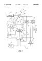
- FIG. 1is a simplified block diagram of a stepper and circuit used to control a dynamic load on the stepper.
- FIG. 2is a block diagram illustrating the methodology whereby the circuit of FIG. 1 is controlled to provide a constant power input into the stepper.
- FIG. 3is a simplified graph illustrating the relationship between power consumed in the human body to power input into an exercising machine or task.
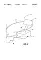
- FIG. 4is a perspective view of the machine operated according to the teachings of FIGS. 1-3 for which an improved wrap around handrail is provided.
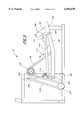
- FIG. 5is a simplified side elevational view of a four-bar linkage which may be used according to the invention to vary the angle of orientation of the foot pedal of the stepper.
- An exercise machinewhich is entirely self-contained without any source of outside power.
- a rechargeable batteryis used to maintain the exercise system operative for a time-out period. At all other times the machine is powered by the user.
- the machineis compact, light, rigid and sized to fit through a standard doorway.
- the entire exercise machineis provided with a wrap-around handrail into which a display input/output unit has been integrally provided.
- the exercise machine or stepperutilizes a dynamically controllable load or alternator which is controlled by a computer circuit to maintain the power input into the exercise machine or to maintain metabolically energy consumption rate within a user of the exercise machine at a predetermined, approximately constant level, regardless of the speed of stepping or the actual or effective weight of the user.
- the alternatoris dynamically controlled by pulse width modulating its field coils.
- the power output by the generatoris sensed by monitoring the alternator's output current and voltage. Additional load control is achieved by dissipating part of the alternator current in a dissipative load when the alternator voltage reaches a predetermined maximum set point.
- FIG. 1is a simplified block diagram of a system, generally denoted by reference numeral 10, for a power controlled exercising machine or stepper.
- a power controlled exercising machine or stepperfor a power controlled exercising machine or stepper.
- FIG. 4One example of a stepper or climbing machine in which the system of FIG. 1 is utilized is shown in perspective view in FIG. 4.
- Exercise stepper 10 of FIG. 4includes a wrap-around support rail 88 connected by means of stanchion 90 to a base 92. Coupled on support rail 88 is a terminal and display, or input/output unit 31.
- Base 92includes mechanical stepper 12 and in particular a pair of independently operated pedal assemblies 94. No exterior power connection is provided or required with system 10.
- Display 31is integrally formed with wraparound rail 88, which provides a construction which is more rugged, more reliable and less prone to damage or misadjustment.
- stepper 10The maximum width 96 of stepper 10 is particularly chosen to be slightly below the standard residential doorway width.
- system 10which may be provided with collapsible rollers beneath base 92 (not shown), can be easily moved through the residential doorway without struggle or the need to disassemble system 10.
- stepper 12is to be construed as any type of exercise equipment or device whereby a human exerciser may translate exercise of any one of the limbs or portion of the body into a motion which is translated into a motive force capable of driving a load.
- stepper 12is meant to include rowing machines, treadmills, climbing machines, skiing machines, skating machines and any type of exercise or work load machine now known or later devised.
- the loadis a dynamic load diagrammatically illustrated in FIG. 1 as an alternator 14.
- Any type of loadmay be utilized in connection with system 10 of FIG. 1 and with the methodology of FIG. 2 consistent with the spirit of the scope of the teachings of the invention. Therefore, generators, friction brakes, pony brakes, air brakes, dynamometers, and any other type of dynamic or controllable load device now known or later devised can be used in place of alternator 14.
- alternator 14is mechanically coupled to stepper 12 by a drive or transmission diagrammatically depicted in FIG. 1 as line 16.
- the actual connectionmay be a shaft, chain, transmission, belt or any means for transmitting or transforming motion.
- the electrical output of alternator 14is shown as a ground terminal 18 and a power terminal 20 having an output voltage V.
- Exerciser system 10 of the present inventionis self-contained. That is, it provides substantially all of its own electrical power for operation through the exerciser's input. Battery assisted startup is provided as described below.
- the principal energy source for the circuitry for controlling system 10is the power input by the exerciser him or herself.
- This output power voltageis provided on line 22 to field control circuit 24.
- the voltageis also provide to a voltage sense circuit 26 which has an analog output on line 28 coupled to the analog to digital converter inputs of a central processing unit (CPU) 30.
- CPUcentral processing unit
- Output voltage V on node 20is also supplied to a load control circuit 32.
- Load control circuithas coupled to it a conventional resistive electrical load 34.
- Load control circuit 32selectively provides a varying degree of current to resistive load 34 according to control received by load control circuit 32 on line 36 from CPU 30.
- the current being delivered to load 34is sensed by current sense circuit 38 which is coupled to load control circuit 32, or if desired, may obtain its sensing pickup from load 34.
- the sensed, current input to circuit 38is then provided on line 40 to the analog to digital converter input of CPU 30.
- CPU 30has both the current being output by alternator 14 and the voltage from alternator 14 available as digital inputs for generating a dynamic control command.
- the product of these two variablesis the electrical power which is being consumed within system 10.
- CPU 30develops a control or command signal which is applied on control line 42 to field control circuit 24.
- Field control circuit 24in turn provides as its output on line 44 the field coils of alternator 14.
- the command signal on line 42is a command signal, which is used to pulse width modulate the field coil current in alternator 14.
- a tachometer 46Mechanically coupled to alternator 14 by a conventional mechanical means 45 is a tachometer 46, which has electrical outputs indicative of the speed at which alternator is being turned.
- One such outputis provided on line 48 as an input to switch 54 to switch battery power to CPU 30 and field control 24.
- Another outputis provided on line 50 to an amplifier 52 and feeds to CPU 30 once the CPU is "on”.
- CPU 30holds switch 54 "on” even after the alternator stops operating and keeps the power on for 30 seconds.
- system 10can during startup and thereafter during an operation have the electrical power requirements of the control circuitry of system 10 powered either by means of battery circuit 56 or by alternator 14.
- the battery circuitthen is connected through switch 54 to field control circuit 24 which enters a startup routine to flash the field coils on alternator 14 to bring the output voltage of alternator 14 up to the 5-volt logic level required to power the remaining elements within the circuitry of system 10, including CPU 30.
- field control circuit 24enters a startup routine to flash the field coils on alternator 14 to bring the output voltage of alternator 14 up to the 5-volt logic level required to power the remaining elements within the circuitry of system 10, including CPU 30.
- battery circuit 56is switched into the system as the power source by switch 54 for a predetermined period of time after which tachometer 46 indicates that alternator 14 is no longer being turned.
- the time out periodis variable and in the illustrated embodiment, it may be preset at 30 seconds. This allows the user to step off the machine, attend to another matter for a short period, and then return without loss of the input or control data within CPU 30 and display 31. For example, the user may set the machine at 100 calorie per rate metabolic output for a 30-minute exercise period. After 18 minutes, the user may for some reason decide to step off the machine for a short period.
- the usermay return to the machine and resume the exercise session without any loss of the input power rating or exercise level desired or loss of recordation of the elapsed time of the exercise session completed up to that point.
- Power usage within the control circuitry of the system of FIG. 10is relatively minor and can be easily sustained for considerable periods by battery circuit 56 without unduly discharging the battery during normal exercise usages.
- CPU 30includes both RAM and ROM program memory for operating the control algorithm shown in FIG. 2.
- Digital representations of the current, I, and voltage, V, output by alternator 14are combined in CPU 32 in a product which is representative of the electrical power being resistively dissipated or consumed within system 10.
- the digital signalsare time dependent and thus power phase can be included in the power computation.
- the output of software module 62can then be conceptionally thought of as the algebraic product, K 1 IV, where K 1 is a scaling factor.
- stepper 12In addition to the electrical power being consumed by system 10, a certain amount of mechanical power is also being input into the mechanical elements of stepper system 10.
- stepper 12as shown in FIG. 4 has a pair of independently operated pedals upon which the exerciser stands and pumps. Each of these pedals is spring loaded so that a certain amount of force is required to lower the pedal against the return spring force. When the exerciser lifts his foot, the spring contracts and raises the pedal to its return position. In addition, there is a predetermined amount of friction and air resistance in the entire stepper mechanism 12.
- Both the distributed frictional load in stepper 12 as well as the amount of energy put in to the spring return extensions of the pedalshas a mechanical power input which is proportional to how fast the exerciser steps, which in turn is related to the speed at which alternator 14 turns.
- tachometer 46provides an alternator speed signal depicted in FIG. 2 as an input to software module 64 wherein it is multiplied by an appropriate scaling factor K 2 to produce a product K 2 S which is equal to the mechanical power input into system 10.
- the scaling factors, K 1 and K 2can be theoretically estimated and/or empirically determined.
- the human userinputs into the input/output circuit 31 a desired power level which may be quantitatively calibrated in terms of calories per hour, calories per minute, watts, horsepower or Joules per minute.
- the userpresets a number, N, which is a the goal number indicating the power at which the user wishes to maintain his input into system 10.
- the set Nis then used in software module 66 to generate a command or power set level, P set .
- the computed power levels P mech and P elecare then summed and compared to the set power level P set in a comparator software module 68.
- the difference between P set and the sum of P mech and P elecis an error signal indicating the margin by which the user's actual power output exceeds or lags the power level which is desired.
- This error signal, Eis then input into a software module 70 which develops a command signal according to the specific requirements and nature of system 10.
- the command signalis then used to create a pulse width modulated field command signal in software module 72.
- the pulse width modulated command signalis then provided on control line 42 from CPU 32 to field control circuit 24 to dynamically set the mechanical load provided by alternator 14 by pulse width modulation of the field coil currents in alternator 14.
- a load control commandis also provided by CPU 30 on line 36 to load control circuit 32.
- the power output by alternator 14is principally controlled by the pulse width modulation of the current in the field coils of alternator 14, which is controlled by the command signal on line 44 from field control circuit 24. However, until the output voltage on node 20 of alternator 14 has reached a predetermined level, for example 10 volts, load control 32 is controlled by CPU 30 to shunt none of the current into load 34. Instead, the required load is provided by appropriate pulse width modulation of the field coil current in alternator 14.
- FIG. 3illustrates the conceptional relationship between power input into system 10 which is the sum of the electrical power absorbed within system 10 and the mechanical power absorbed within system 10 and the metabolic energy usage rate in the human exerciser.
- the vertical scale 74 of the graph of FIG. 3is the power input into system 10, while the horizontal axis 76 represents the metabolic power actually being consumed in the human user in both motive force and total muscle energy consumption rates, which be manifested in energy losses through respiration, sweat and radiant heat.
- the human machinehas a nonlinear efficiency. In other words, as the actual motive work rate output of the human machine increases, the total rate of metabolic energy usage increases more rapidly so that power output as a function of metabolic power falls off as generally indicated by curve 78 from a linear relationship indicated by line 80.
- a graph or look-up table of the nature of FIG. 3can be constructed and stored within the memory of CPU 30.
- the sum of the mechanical electrical power developed by the exerciser from modules 62 and 64can be summed in a module 88 and then an average total metabolic power rate derived from a look up table based on data as depicted in FIG. 3 for use in software module 68 to produce the error signal, E.
- the userthen inputs an energy rate into I/O unit 31, which is then translated into software module 66 of FIG. 2 which represents, not the power to be maintained by the exercise level in stepping system 10, but instead the power which the human machine itself, the metabolic rate of the human exerciser, totally consumes in order to maintain the selected exercise level.
- the alternator field coilsare flashed on, and the alternator voltage rises as the control logic within system 10, referred to as the upper board circuitry, powers up and comes on line.
- the voltage on alternator 14is at 5 volts or above thereby fully powering the upper board circuitry.
- the field coils on alternator 14are then pulse width modulated to provide the appropriate load to the user. If this load can be provided at a voltage output of alternator 14 below 10 volts, no substantial amount of current is dissipated in load 34.
- alternator 14is then controlled to provide a greater load so that the amount of power which the user must input into the machine remains approximately constant. If the user for any purpose should lean on the support railings provided with system 10 as shown in FIG. 4, the force on the pedals to the other user's feet will decrease, and again the circuitry of the invention will modulate the field windings of alternator 10 to increase the load so that approximately the same amount of power is input into the machine or output from the exerciser.
- the heavier userwill be able to maintain the power setting input by the lighter user at a lower stepping rate, because the circuitry of system 10 will immediately sense the increased torque applied to alternator 14 through stepper 12.
- the resistance or load provided by alternator 14 and/or shunted to dissipative load 34will be adjusted to keep the input power or metabolic power of the user approximately constant.
- the steppermay be operated to comprise a deliberate insertion of a seed number by the user.
- the seed numberis determined by the total elapsed time which has passed in the exercise between initiation and when a variable mode is entered by manual push button by the user into I/O device 31 in FIG. 1.
- Initiationcan be defined as any start-up event, such as the time at which the output of alternator 14 achieves a predetermined output voltage level or tachometer 46 a predetermined speed output.
- Elapsed time in secondsis divided modulo 240 (4 minutes) to obtain a remainder. The remainder in seconds is then a memory location between 0 and 239 in which a load value is prestored.
- CPU 30should be understood as including on-chip or associated read-only memory as well as random access memory used for normal processing functions.
- the next 20 consecutive memory locationsare then read at one minute intervals to establish load instructions from CPU 30 to provide a varied 20 minute workout.
- Memory readwraps around from location 239 to 0 in a cyclic manner so that in the space of a 20 minute workout the load sequence wraps around or repeats five times or once every four minutes.
- the sequence of load values in the memory locationsare prestored and predetermined and cannot be varied by the user.
- the usercan deliberately select a repeatable exercise sequence by always entering the sequence at the same time or times modulo 240. There is no randomness or pseudo-randomness in the manner in which the exercise sequences are provided, beyond any human randomness or pseudo-randomness, if any, chosen by the user as the start point of the varied prestored sequence. If there is any randomness it is a function of human behavior and not that of the apparatus. Thus the user has the option of entering the load sequence at any point which allows the user to have a varied, but predictable exercise session.
- FIG. 5is a simplified side elevational view of one embodiment exercise system 10 illustrating the linkages between pedal 94 and other elements of the system.
- Pedal 94is coupled to a pedal arm 98 about a pivot pin 100.
- the opposing end of arm 98is pivoted to a frame 102 about a pivot pin 104.
- a flange 106extending vertically above pedal surface 108 from the side of pedal 94, is pivotally coupled to an upper arm 110 about a pivot pin 112.
- Opposing end of upper arm 110is pivotally coupled to frame 102 about a pivot pin 114.
- pedal 94is supported by a four-bar linkage comprised of frame 102, pedal arm 98, pedal 94 and upper arm 110.
- the four-bar linkage shown in FIG. 5is comprised of two non-parallel arms.
- An imaginary line between pivot pins 104 and 100 coupled to arm 98is nonparallel to a similarly constructed imaginary line between pivots 114 and 112 of arm 110.
- the result of two nonparallel opposing arms in a four-bar linkagemeans that the treadle surface 108 of pedal 94 changes its inclination as the four-bar linkage rotates upwardly and downwardly as symbolically denoted by arrow 116.
- the inclined pedalprovides for a more gentle or rocking support for the exerciser's feet to reduce the amount of ankle flexure required from the exerciser between the position when the pedal is closest to the floor and compared to its maximum up position.
- Rotation of the four-bar linkageextends or retracts a chain or toothed belt 118 which engages gear or sprocket 120.
- Opposing end 122 of chain 118is then connected to an extension spring 124 which is wrapped around an idler pulley 126 and fixed at its opposing end 128 to frame 102.
- Spring 124returns pedal 94 and its associated linkages to an up position.
- An identical four-bar linkage, chain, sprocket and spring returnis provided for the opposing pedal 94 on the opposite side of system 10 so the pedals may operate independently of each other in a user-controlled stepping action.
Landscapes
- Health & Medical Sciences (AREA)
- General Health & Medical Sciences (AREA)
- Physical Education & Sports Medicine (AREA)
- Physics & Mathematics (AREA)
- Electromagnetism (AREA)
- Life Sciences & Earth Sciences (AREA)
- Biophysics (AREA)
- Orthopedic Medicine & Surgery (AREA)
- Cardiology (AREA)
- Vascular Medicine (AREA)
- Rehabilitation Tools (AREA)
Abstract
Description
Claims (15)
Priority Applications (5)
| Application Number | Priority Date | Filing Date | Title |
|---|---|---|---|
| US08/249,248US6056670A (en) | 1994-05-25 | 1994-05-25 | Power controlled exercising machine and method for controlling the same |
| PCT/US1995/006622WO1995032028A1 (en) | 1994-05-25 | 1995-05-24 | Power controlled exercising machine and method for controlling the same |
| AU26488/95AAU2648895A (en) | 1994-05-25 | 1995-05-24 | Power controlled exercising machine and method for controlling the same |
| US08/607,822US6176813B1 (en) | 1994-05-25 | 1996-02-27 | Power controlled exercising machine and method for controlling the same |
| US09/768,775US6511402B2 (en) | 1994-05-25 | 2001-01-23 | Power controlled exercising machine and method for controlling the same |
Applications Claiming Priority (1)
| Application Number | Priority Date | Filing Date | Title |
|---|---|---|---|
| US08/249,248US6056670A (en) | 1994-05-25 | 1994-05-25 | Power controlled exercising machine and method for controlling the same |
Related Child Applications (1)
| Application Number | Title | Priority Date | Filing Date |
|---|---|---|---|
| US08/607,822DivisionUS6176813B1 (en) | 1994-05-25 | 1996-02-27 | Power controlled exercising machine and method for controlling the same |
Publications (1)
| Publication Number | Publication Date |
|---|---|
| US6056670Atrue US6056670A (en) | 2000-05-02 |
Family
ID=22942639
Family Applications (3)
| Application Number | Title | Priority Date | Filing Date |
|---|---|---|---|
| US08/249,248Expired - LifetimeUS6056670A (en) | 1994-05-25 | 1994-05-25 | Power controlled exercising machine and method for controlling the same |
| US08/607,822Expired - LifetimeUS6176813B1 (en) | 1994-05-25 | 1996-02-27 | Power controlled exercising machine and method for controlling the same |
| US09/768,775Expired - Fee RelatedUS6511402B2 (en) | 1994-05-25 | 2001-01-23 | Power controlled exercising machine and method for controlling the same |
Family Applications After (2)
| Application Number | Title | Priority Date | Filing Date |
|---|---|---|---|
| US08/607,822Expired - LifetimeUS6176813B1 (en) | 1994-05-25 | 1996-02-27 | Power controlled exercising machine and method for controlling the same |
| US09/768,775Expired - Fee RelatedUS6511402B2 (en) | 1994-05-25 | 2001-01-23 | Power controlled exercising machine and method for controlling the same |
Country Status (3)
| Country | Link |
|---|---|
| US (3) | US6056670A (en) |
| AU (1) | AU2648895A (en) |
| WO (1) | WO1995032028A1 (en) |
Cited By (28)
| Publication number | Priority date | Publication date | Assignee | Title |
|---|---|---|---|---|
| US20030166434A1 (en)* | 2002-03-01 | 2003-09-04 | Illinois Tool Works, Inc. | Self-powered fitness equipment |
| US6672157B2 (en)* | 2001-04-02 | 2004-01-06 | Northern Illinois University | Power tester |
| US20070149364A1 (en)* | 2005-12-22 | 2007-06-28 | Blau David A | Exercise device |
| US20090011907A1 (en)* | 2007-06-27 | 2009-01-08 | Radow Scott B | Stationary Exercise Equipment |
| US20090149553A1 (en)* | 2003-02-04 | 2009-06-11 | Cole Jantzen A | Injectable resorbable bone graft material, powder for forming same and methods relating thereto for treating bone defects |
| US20090315336A1 (en)* | 2008-06-23 | 2009-12-24 | Hudson Worthington Harr | Renewable energy generation system |
| US20110015041A1 (en)* | 1995-06-22 | 2011-01-20 | Shea Michael J | Exercise System |
| US20110118086A1 (en)* | 2005-12-22 | 2011-05-19 | Mr. Scott B. Radow | Exercise device |
| US8298123B2 (en) | 1995-12-14 | 2012-10-30 | Icon Health & Fitness, Inc. | Method and apparatus for remote interactive exercise and health equipment |
| US8690735B2 (en) | 1999-07-08 | 2014-04-08 | Icon Health & Fitness, Inc. | Systems for interaction with exercise device |
| US8758201B2 (en) | 1999-07-08 | 2014-06-24 | Icon Health & Fitness, Inc. | Portable physical activity sensing system |
| US9028368B2 (en) | 1999-07-08 | 2015-05-12 | Icon Health & Fitness, Inc. | Systems, methods, and devices for simulating real world terrain on an exercise device |
| US20160380512A1 (en)* | 2010-02-23 | 2016-12-29 | Catalyst Design And Development | Pedal generator assembly |
| US10046222B2 (en)* | 2012-08-27 | 2018-08-14 | Wahoo Fitness, LLC | System and method for controlling a bicycle trainer |
| US10188890B2 (en) | 2013-12-26 | 2019-01-29 | Icon Health & Fitness, Inc. | Magnetic resistance mechanism in a cable machine |
| US10220259B2 (en) | 2012-01-05 | 2019-03-05 | Icon Health & Fitness, Inc. | System and method for controlling an exercise device |
| US10226396B2 (en) | 2014-06-20 | 2019-03-12 | Icon Health & Fitness, Inc. | Post workout massage device |
| US10272317B2 (en) | 2016-03-18 | 2019-04-30 | Icon Health & Fitness, Inc. | Lighted pace feature in a treadmill |
| US10279212B2 (en) | 2013-03-14 | 2019-05-07 | Icon Health & Fitness, Inc. | Strength training apparatus with flywheel and related methods |
| US10391361B2 (en) | 2015-02-27 | 2019-08-27 | Icon Health & Fitness, Inc. | Simulating real-world terrain on an exercise device |
| US10426989B2 (en) | 2014-06-09 | 2019-10-01 | Icon Health & Fitness, Inc. | Cable system incorporated into a treadmill |
| US10433612B2 (en) | 2014-03-10 | 2019-10-08 | Icon Health & Fitness, Inc. | Pressure sensor to quantify work |
| US10493349B2 (en) | 2016-03-18 | 2019-12-03 | Icon Health & Fitness, Inc. | Display on exercise device |
| US10610725B2 (en) | 2015-04-20 | 2020-04-07 | Crew Innovations, Llc | Apparatus and method for increased realism of training on exercise machines |
| US10625137B2 (en) | 2016-03-18 | 2020-04-21 | Icon Health & Fitness, Inc. | Coordinated displays in an exercise device |
| US10671705B2 (en) | 2016-09-28 | 2020-06-02 | Icon Health & Fitness, Inc. | Customizing recipe recommendations |
| CN114159726A (en)* | 2021-12-02 | 2022-03-11 | 广东明伦光电科技有限公司 | Stepping machine |
| US11364419B2 (en) | 2019-02-21 | 2022-06-21 | Scott B. Radow | Exercise equipment with music synchronization |
Families Citing this family (32)
| Publication number | Priority date | Publication date | Assignee | Title |
|---|---|---|---|---|
| US20030073546A1 (en)* | 2001-09-28 | 2003-04-17 | Lassanske Todd W. | Self-powered variable resistance bicycle trainer |
| GB0312287D0 (en)* | 2003-05-29 | 2003-07-02 | Pulse Fitness Ltd | Improved exercise apparatus |
| US20070042868A1 (en)* | 2005-05-11 | 2007-02-22 | John Fisher | Cardio-fitness station with virtual- reality capability |
| US20070197345A1 (en)* | 2006-02-13 | 2007-08-23 | Wallace Gregory A | Motivational displays and methods for exercise machine |
| US20080207402A1 (en)* | 2006-06-28 | 2008-08-28 | Expresso Fitness Corporation | Closed-Loop Power Dissipation Control For Cardio-Fitness Equipment |
| US7762931B2 (en)* | 2007-04-18 | 2010-07-27 | Interactive Fitness Holdings, LLC | Seat for cardio-fitness equipment |
| US20090118099A1 (en)* | 2007-11-05 | 2009-05-07 | John Fisher | Closed-loop power dissipation control for cardio-fitness equipment |
| US20090247366A1 (en)* | 2008-03-26 | 2009-10-01 | Frumer John D | Method and apparatus for configuring fitness equipment |
| US8069794B2 (en)* | 2008-04-22 | 2011-12-06 | Satloff Theodore J | Portable computer desk with power generator |
| US20100035726A1 (en)* | 2008-08-07 | 2010-02-11 | John Fisher | Cardio-fitness station with virtual-reality capability |
| US20100036736A1 (en)* | 2008-08-08 | 2010-02-11 | Expresso Fitness Corp. | System and method for revenue sharing with a fitness center |
| US20110165997A1 (en)* | 2008-08-22 | 2011-07-07 | Alton Reich | Rotary exercise equipment apparatus and method of use thereof |
| US20110172058A1 (en)* | 2008-08-22 | 2011-07-14 | Stelu Deaconu | Variable resistance adaptive exercise apparatus and method of use thereof |
| US20110195819A1 (en)* | 2008-08-22 | 2011-08-11 | James Shaw | Adaptive exercise equipment apparatus and method of use thereof |
| US20110165996A1 (en)* | 2008-08-22 | 2011-07-07 | David Paulus | Computer controlled exercise equipment apparatus and method of use thereof |
| US20110165995A1 (en)* | 2008-08-22 | 2011-07-07 | David Paulus | Computer controlled exercise equipment apparatus and method of use thereof |
| US20100077564A1 (en)* | 2008-09-29 | 2010-04-01 | Espresso Fitness Corp. | Hinge apparatus to facilitate position adjustment of equipment |
| ITRA20110005A1 (en)* | 2011-02-08 | 2012-08-09 | Technogym Spa | GINNICA MACHINE |
| CN102728024B (en)* | 2012-07-11 | 2015-02-18 | 山东汇康运动器材有限公司 | Speed regulation method free of external power mountain climbing machine and device thereof |
| US9457217B2 (en)* | 2013-03-20 | 2016-10-04 | Wuji Yin | Body-building power generation apparatus and a method of generating power using the same |
| US10618472B2 (en) | 2015-08-04 | 2020-04-14 | T-Max (Hangzhou) Technology Co., Ltd. | Vehicle and vehicle step apparatus with multiple drive motors |
| US10625114B2 (en) | 2016-11-01 | 2020-04-21 | Icon Health & Fitness, Inc. | Elliptical and stationary bicycle apparatus including row functionality |
| US11198394B2 (en) | 2018-07-20 | 2021-12-14 | T-Max (Hangzhou) Technology Co., Ltd. | Vehicle running board apparatus and retractable device thereof |
| US10384614B1 (en) | 2018-07-20 | 2019-08-20 | T-Max (Hangzhou) Technology Co., Ltd. | Vehicle, running board assembly and drive assembly for running board |
| CN110012061B (en) | 2019-02-20 | 2022-02-08 | 杭州天铭科技股份有限公司 | Management device for vehicle equipment, vehicle, and server |
| WO2020172914A1 (en) | 2019-02-28 | 2020-09-03 | 杭州天铭科技股份有限公司 | Winch, rope guide, and transmission device with clutch function |
| WO2020177186A1 (en) | 2019-03-05 | 2020-09-10 | 杭州天铭科技股份有限公司 | Vehicle step bar device and vehicle |
| WO2020181617A1 (en) | 2019-03-11 | 2020-09-17 | 杭州天铭科技股份有限公司 | Adjustment apparatus, adjuster, and shock absorber |
| FR3096268B1 (en)* | 2019-05-20 | 2021-06-04 | Mescirowing Holding | Exercise machine |
| US11584387B2 (en) | 2019-09-16 | 2023-02-21 | T-Max (Hangzhou) Technology Co., Ltd. | Step apparatus for vehicle and vehicle |
| WO2021227617A1 (en) | 2020-05-11 | 2021-11-18 | 杭州天铭科技股份有限公司 | Vehicle pedal apparatus and vehicle |
| WO2021227616A1 (en) | 2020-05-11 | 2021-11-18 | 杭州天铭科技股份有限公司 | Vehicle footboard device and vehicle |
Citations (4)
| Publication number | Priority date | Publication date | Assignee | Title |
|---|---|---|---|---|
| US4298893A (en)* | 1980-08-29 | 1981-11-03 | Holmes James H | T.V. Energized by exercise cycle |
| US4542897A (en)* | 1983-10-11 | 1985-09-24 | Melton Donald L | Exercise cycle with interactive amusement device |
| US5246412A (en)* | 1992-06-25 | 1993-09-21 | Chen Meng S | Self-energizing ski-practicing device |
| US5403252A (en)* | 1992-05-12 | 1995-04-04 | Life Fitness | Exercise apparatus and method for simulating hill climbing |
Family Cites Families (114)
| Publication number | Priority date | Publication date | Assignee | Title |
|---|---|---|---|---|
| US219439A (en) | 1879-09-09 | Improvement in passive-motion walking-machines | ||
| US1909190A (en) | 1931-02-03 | 1933-05-16 | Sachs Jacques | Exercising apparatus |
| US2826192A (en) | 1955-10-18 | 1958-03-11 | James E Mangas | Therapeutic electrical exerciser |
| US2892455A (en) | 1957-09-27 | 1959-06-30 | Leach L Hutton | Walking trainer and coordinator |
| US3316898A (en) | 1964-10-23 | 1967-05-02 | James W Brown | Rehabilitation and exercise apparatus |
| CH443088A (en) | 1966-12-12 | 1967-08-31 | Rueegsegger Walter | Training apparatus for skiers |
| US3566861A (en) | 1969-04-18 | 1971-03-02 | Beacon Enterprises Inc | Exerciser and physical rehabilitation apparatus |
| US3759511A (en) | 1971-03-29 | 1973-09-18 | K Gustafson | Adjustable friction type exercising device |
| US3756595A (en) | 1971-04-23 | 1973-09-04 | G Hague | Leg exercising device for simulating ice skating |
| US3713438A (en) | 1971-05-06 | 1973-01-30 | M Knutsen | Therapeutic exercising apparatus |
| US3824994A (en) | 1973-01-29 | 1974-07-23 | R S Reciprocating Trainer Ente | Reciprocating walker |
| US3970302A (en) | 1974-06-27 | 1976-07-20 | Mcfee Richard | Exercise stair device |
| US4053173A (en) | 1976-03-23 | 1977-10-11 | Chase Sr Douglas | Bicycle |
| US4188030A (en) | 1976-10-18 | 1980-02-12 | Repco Limited | Cycle exerciser |
| US4185622A (en) | 1979-03-21 | 1980-01-29 | Swenson Oscar J | Foot and leg exerciser |
| US4379566A (en) | 1981-01-26 | 1983-04-12 | Creative Motion Industries, Inc. | Operator powered vehicle |
| US4456276A (en) | 1981-04-15 | 1984-06-26 | Peter Bortolin | Bicycle assembly |
| US4561318A (en) | 1981-10-05 | 1985-12-31 | Schirrmacher Douglas R | Lever power system |
| US4496147A (en) | 1982-03-12 | 1985-01-29 | Arthur D. Little, Inc. | Exercise stair device |
| US4509742A (en) | 1983-06-06 | 1985-04-09 | Cones Charles F | Exercise bicycle |
| US4555109A (en) | 1983-09-14 | 1985-11-26 | Hartmann Joseph C | Exercising machine |
| US4687195A (en) | 1984-02-06 | 1987-08-18 | Tri-Tech, Inc. | Treadmill exerciser |
| US4720093A (en) | 1984-06-18 | 1988-01-19 | Del Mar Avionics | Stress test exercise device |
| US4685666A (en) | 1984-08-27 | 1987-08-11 | Decloux Richard J | Climbing simulation exercise device |
| US4592544A (en) | 1984-10-09 | 1986-06-03 | Precor Incorporated | Pedal-operated, stationary exercise device |
| US4632386A (en) | 1985-01-30 | 1986-12-30 | Allegheny International Exercise Co. | Foldable exercise cycle |
| US4645200A (en) | 1985-05-28 | 1987-02-24 | Hix William R | Isometric exercising device |
| US5062627A (en) | 1991-01-23 | 1991-11-05 | Proform Fitness Products, Inc. | Reciprocator for a stepper exercise machine |
| US4733858A (en) | 1986-05-23 | 1988-03-29 | Lan Chuang S | Multi-purpose exerciser |
| US4708338A (en) | 1986-08-04 | 1987-11-24 | Potts Lanny L | Stair climbing exercise apparatus |
| US4786050A (en) | 1986-11-06 | 1988-11-22 | Geschwender Robert C | Exercise machine |
| US4709918A (en) | 1986-12-29 | 1987-12-01 | Arkady Grinblat | Universal exercising apparatus |
| US4779863A (en) | 1987-06-26 | 1988-10-25 | Yang Kuey M | Running exercise bicycle |
| US5000443A (en) | 1987-09-08 | 1991-03-19 | Weslo, Inc. | Striding exerciser |
| US4850585A (en) | 1987-09-08 | 1989-07-25 | Weslo, Inc. | Striding exerciser |
| US5131895A (en) | 1988-01-27 | 1992-07-21 | Rogers Jr Robert E | Exercise apparatus |
| US4940233A (en) | 1988-02-19 | 1990-07-10 | John Bull | Aerobic conditioning apparatus |
| US5135447A (en) | 1988-10-21 | 1992-08-04 | Life Fitness | Exercise apparatus for simulating stair climbing |
| US5295928A (en) | 1989-01-31 | 1994-03-22 | Rennex Brian G | Bi-directional stair/treadmill/reciprocating-pedal exerciser |
| US5186697A (en) | 1989-01-31 | 1993-02-16 | Rennex Brian G | Bi-directional stair/treadmill/reciprocating-pedal exerciser |
| US5067710A (en) | 1989-02-03 | 1991-11-26 | Proform Fitness Products, Inc. | Computerized exercise machine |
| US4869494A (en) | 1989-03-22 | 1989-09-26 | Lambert Sr Theodore E | Exercise apparatus for the handicapped |
| US4949954A (en) | 1989-05-04 | 1990-08-21 | Hix William R | Jointed bicycle-simulation device for isometric exercise |
| US4951942A (en) | 1989-05-22 | 1990-08-28 | Walden Jerold A | Multiple purpose exercise device |
| US4949993A (en) | 1989-07-31 | 1990-08-21 | Laguna Tectrix, Inc. | Exercise apparatus having high durability mechanism for user energy transmission |
| US5000442A (en) | 1990-02-20 | 1991-03-19 | Proform Fitness Products, Inc. | Cross country ski exerciser |
| US5039088A (en) | 1990-04-26 | 1991-08-13 | Shifferaw Tessema D | Exercise machine |
| US5040786A (en) | 1990-05-08 | 1991-08-20 | Jou W K | Rehabilitation device |
| US5039087A (en) | 1990-05-11 | 1991-08-13 | Kuo Hai Pin | Power stairclimber |
| US4989857A (en) | 1990-06-12 | 1991-02-05 | Kuo Hai Pin | Stairclimber with a safety speed changing device |
| US5139469A (en) | 1990-08-02 | 1992-08-18 | Zurn Industries, Inc. | Exercise machine and transmission therefor |
| EP0472332B1 (en) | 1990-08-09 | 1995-11-08 | Victor Company Of Japan, Limited | Circuit for generating a clock signal which is locked to a specific phase of a color burst signal in a color video signal |
| US5256117A (en)* | 1990-10-10 | 1993-10-26 | Stairmaster Sports Medical Products, Inc. | Stairclimbing and upper body, exercise apparatus |
| US5048821A (en) | 1990-11-23 | 1991-09-17 | Kuo Liang Wang | Stepping exerciser step plates link motion mechanism |
| US5195935A (en) | 1990-12-20 | 1993-03-23 | Sf Engineering | Exercise apparatus with automatic variation of provided passive and active exercise without interruption of the exercise |
| US5238462A (en) | 1991-02-20 | 1993-08-24 | Life Fitness | Stair climbing exercise apparatus utilizing drive belts |
| US5078389A (en) | 1991-07-19 | 1992-01-07 | David Chen | Exercise machine with three exercise modes |
| US5163888A (en) | 1992-02-25 | 1992-11-17 | Stearns Kenneth W | Exercise apparatus |
| US5279529A (en) | 1992-04-16 | 1994-01-18 | Eschenbach Paul W | Programmed pedal platform exercise apparatus |
| US5320588A (en) | 1992-07-23 | 1994-06-14 | Precor Incorporated | Independent action exercise apparatus with adjustably mounted linear resistance devices |
| US5242343A (en) | 1992-09-30 | 1993-09-07 | Larry Miller | Stationary exercise device |
| US5290211A (en) | 1992-10-29 | 1994-03-01 | Stearns Technologies, Inc. | Exercise device |
| US5403255A (en) | 1992-11-02 | 1995-04-04 | Johnston; Gary L. | Stationary exercising apparatus |
| US5299993A (en)* | 1992-12-01 | 1994-04-05 | Pacific Fitness Corporation | Articulated lower body exerciser |
| US5529554A (en) | 1993-04-22 | 1996-06-25 | Eschenbach; Paul W. | Collapsible exercise machine with multi-mode operation |
| US5352169A (en) | 1993-04-22 | 1994-10-04 | Eschenbach Paul W | Collapsible exercise machine |
| USD355006S (en) | 1993-10-08 | 1995-01-31 | Lo Peter K -C | Stepper exerciser |
| US5419747A (en) | 1994-01-27 | 1995-05-30 | Piaget; Gary D. | Striding-type exercise apparatus |
| US5423729A (en) | 1994-08-01 | 1995-06-13 | Eschenbach; Paul W. | Collapsible exercise machine with arm exercise |
| US5542897A (en)* | 1995-01-17 | 1996-08-06 | Hall; Timothy L. | Exercise pump device |
| US5593372A (en) | 1995-01-25 | 1997-01-14 | Ccs, Llc | Stationary exercise apparatus having a preferred foot platform path |
| US5595553A (en) | 1995-01-25 | 1997-01-21 | Ccs, Llc | Stationary exercise apparatus |
| US5527246A (en) | 1995-01-25 | 1996-06-18 | Rodgers, Jr.; Robert E. | Mobile exercise apparatus |
| US5573480A (en) | 1995-01-25 | 1996-11-12 | Ccs, Llc | Stationary exercise apparatus |
| US5591107A (en) | 1995-01-25 | 1997-01-07 | Rodgers, Jr.; Robert E. | Mobile exercise apparatus |
| US5690589A (en) | 1995-01-25 | 1997-11-25 | Rodgers, Jr.; Robert E. | Stationary exercise apparatus |
| US5738614A (en) | 1995-01-25 | 1998-04-14 | Rodgers, Jr.; Robert E. | Stationary exercise apparatus with retractable arm members |
| US5549526A (en) | 1995-01-25 | 1996-08-27 | Ccs, Llc | Stationary exercise apparatus |
| US5529555A (en) | 1995-06-06 | 1996-06-25 | Ccs, Llc | Crank assembly for an exercising device |
| US5540637A (en) | 1995-01-25 | 1996-07-30 | Ccs, Llc | Stationary exercise apparatus having a preferred foot platform orientation |
| US5518473A (en) | 1995-03-20 | 1996-05-21 | Miller; Larry | Exercise device |
| US5692994A (en) | 1995-06-08 | 1997-12-02 | Eschenbach; Paul William | Collapsible exercise machine with arm exercise |
| US5707321A (en) | 1995-06-30 | 1998-01-13 | Maresh; Joseph Douglas | Four bar exercise machine |
| US5735774A (en) | 1995-07-19 | 1998-04-07 | Maresh; Joseph Douglas | Active crank axis cycle mechanism |
| US5496235A (en) | 1995-08-04 | 1996-03-05 | Stevens; Clive G. | Walking exeriser |
| US5658227A (en) | 1995-09-12 | 1997-08-19 | Stearns Technologies, Inc. | Exercise device |
| US5616106A (en) | 1995-09-19 | 1997-04-01 | Abelbeck; Kevin | Exercise device |
| US5741205A (en) | 1995-12-07 | 1998-04-21 | Life Fitness | Exercise apparatus pedal mechanism |
| US5685804A (en) | 1995-12-07 | 1997-11-11 | Precor Incorporated | Stationary exercise device |
| US5577985A (en) | 1996-02-08 | 1996-11-26 | Miller; Larry | Stationary exercise device |
| US5611756A (en) | 1996-02-08 | 1997-03-18 | Miller; Larry | Stationary exercise device |
| US5562574A (en) | 1996-02-08 | 1996-10-08 | Miller; Larry | Compact exercise device |
| US5792029A (en) | 1996-02-21 | 1998-08-11 | Gordon; Trace | Foot skate climbing simulation exercise apparatus and method |
| US5611758A (en) | 1996-05-15 | 1997-03-18 | Ccs, Llc | Recumbent exercise apparatus |
| US5653662A (en) | 1996-05-24 | 1997-08-05 | Rodgers, Jr.; Robert E. | Stationary exercise apparatus |
| US5788610A (en) | 1996-09-09 | 1998-08-04 | Eschenbach; Paul William | Elliptical exercise machine with arm exercise |
| US5792026A (en) | 1997-03-14 | 1998-08-11 | Maresh; Joseph D. | Exercise method and apparatus |
| USD393027S (en) | 1997-03-17 | 1998-03-31 | Chin-Chiao Chen | Walking exerciser |
| US5848954A (en) | 1997-04-15 | 1998-12-15 | Stearns; Kenneth W. | Exercise methods and apparatus |
| US5803871A (en) | 1997-04-24 | 1998-09-08 | Stearns; Kenneth W. | Exercise methods and apparatus |
| US5759135A (en) | 1997-05-29 | 1998-06-02 | Chen; Paul | Stationary exerciser |
| DE29709764U1 (en) | 1997-06-04 | 1997-08-07 | Lee, Kuo-Lung, Yi Lan | Treadmill |
| US5755643A (en) | 1997-07-02 | 1998-05-26 | Sands; Lenny | Folding collapsible step exerciser with damping means |
| US5746683A (en) | 1997-07-16 | 1998-05-05 | Lee; Kuo-Lung | Folding collapsible step exercising machine |
| US5762588A (en) | 1997-07-17 | 1998-06-09 | Chen; Paul | Stationary exerciser |
| US5759136A (en) | 1997-07-17 | 1998-06-02 | Chen; Paul | Exerciser having movable foot supports |
| US5769760A (en) | 1997-07-22 | 1998-06-23 | Lin; Michael | Stationary exercise device |
| US5779598A (en) | 1997-08-18 | 1998-07-14 | Stamina Products, Inc. | Pedal-type exerciser |
| US5779599A (en) | 1997-08-19 | 1998-07-14 | Chen; Paul | Stationary exerciser |
| US5782722A (en) | 1997-08-27 | 1998-07-21 | Sands; Lenny | Structure of folding collapsible step exerciser |
| US5803872A (en) | 1997-10-06 | 1998-09-08 | Chang; Shao Ying | Step exerciser |
| US5820524A (en)* | 1997-10-29 | 1998-10-13 | Chen; Meng Tsung | Walking type exerciser |
| US5800315A (en) | 1997-10-30 | 1998-09-01 | Yu; Hui-Nan | Oval track exercising climber |
| US5836854A (en)* | 1998-02-10 | 1998-11-17 | Kuo; Hai Pin | Roaming excerciser |
- 1994
- 1994-05-25USUS08/249,248patent/US6056670A/ennot_activeExpired - Lifetime
- 1995
- 1995-05-24AUAU26488/95Apatent/AU2648895A/ennot_activeAbandoned
- 1995-05-24WOPCT/US1995/006622patent/WO1995032028A1/enactiveApplication Filing
- 1996
- 1996-02-27USUS08/607,822patent/US6176813B1/ennot_activeExpired - Lifetime
- 2001
- 2001-01-23USUS09/768,775patent/US6511402B2/ennot_activeExpired - Fee Related
Patent Citations (4)
| Publication number | Priority date | Publication date | Assignee | Title |
|---|---|---|---|---|
| US4298893A (en)* | 1980-08-29 | 1981-11-03 | Holmes James H | T.V. Energized by exercise cycle |
| US4542897A (en)* | 1983-10-11 | 1985-09-24 | Melton Donald L | Exercise cycle with interactive amusement device |
| US5403252A (en)* | 1992-05-12 | 1995-04-04 | Life Fitness | Exercise apparatus and method for simulating hill climbing |
| US5246412A (en)* | 1992-06-25 | 1993-09-21 | Chen Meng S | Self-energizing ski-practicing device |
Cited By (33)
| Publication number | Priority date | Publication date | Assignee | Title |
|---|---|---|---|---|
| US20110015041A1 (en)* | 1995-06-22 | 2011-01-20 | Shea Michael J | Exercise System |
| US8057360B2 (en) | 1995-06-22 | 2011-11-15 | Shea Michael J | Exercise system |
| US8298123B2 (en) | 1995-12-14 | 2012-10-30 | Icon Health & Fitness, Inc. | Method and apparatus for remote interactive exercise and health equipment |
| US9028368B2 (en) | 1999-07-08 | 2015-05-12 | Icon Health & Fitness, Inc. | Systems, methods, and devices for simulating real world terrain on an exercise device |
| US8784270B2 (en) | 1999-07-08 | 2014-07-22 | Icon Ip, Inc. | Portable physical activity sensing system |
| US8758201B2 (en) | 1999-07-08 | 2014-06-24 | Icon Health & Fitness, Inc. | Portable physical activity sensing system |
| US8690735B2 (en) | 1999-07-08 | 2014-04-08 | Icon Health & Fitness, Inc. | Systems for interaction with exercise device |
| US6672157B2 (en)* | 2001-04-02 | 2004-01-06 | Northern Illinois University | Power tester |
| US20030166434A1 (en)* | 2002-03-01 | 2003-09-04 | Illinois Tool Works, Inc. | Self-powered fitness equipment |
| US20090149553A1 (en)* | 2003-02-04 | 2009-06-11 | Cole Jantzen A | Injectable resorbable bone graft material, powder for forming same and methods relating thereto for treating bone defects |
| US20110118086A1 (en)* | 2005-12-22 | 2011-05-19 | Mr. Scott B. Radow | Exercise device |
| US7976434B2 (en)* | 2005-12-22 | 2011-07-12 | Scott B. Radow | Exercise device |
| US20070149364A1 (en)* | 2005-12-22 | 2007-06-28 | Blau David A | Exercise device |
| US7862476B2 (en)* | 2005-12-22 | 2011-01-04 | Scott B. Radow | Exercise device |
| US20090011907A1 (en)* | 2007-06-27 | 2009-01-08 | Radow Scott B | Stationary Exercise Equipment |
| US7833135B2 (en) | 2007-06-27 | 2010-11-16 | Scott B. Radow | Stationary exercise equipment |
| US20090315336A1 (en)* | 2008-06-23 | 2009-12-24 | Hudson Worthington Harr | Renewable energy generation system |
| US20160380512A1 (en)* | 2010-02-23 | 2016-12-29 | Catalyst Design And Development | Pedal generator assembly |
| US10220259B2 (en) | 2012-01-05 | 2019-03-05 | Icon Health & Fitness, Inc. | System and method for controlling an exercise device |
| US10046222B2 (en)* | 2012-08-27 | 2018-08-14 | Wahoo Fitness, LLC | System and method for controlling a bicycle trainer |
| US10279212B2 (en) | 2013-03-14 | 2019-05-07 | Icon Health & Fitness, Inc. | Strength training apparatus with flywheel and related methods |
| US10188890B2 (en) | 2013-12-26 | 2019-01-29 | Icon Health & Fitness, Inc. | Magnetic resistance mechanism in a cable machine |
| US10433612B2 (en) | 2014-03-10 | 2019-10-08 | Icon Health & Fitness, Inc. | Pressure sensor to quantify work |
| US10426989B2 (en) | 2014-06-09 | 2019-10-01 | Icon Health & Fitness, Inc. | Cable system incorporated into a treadmill |
| US10226396B2 (en) | 2014-06-20 | 2019-03-12 | Icon Health & Fitness, Inc. | Post workout massage device |
| US10391361B2 (en) | 2015-02-27 | 2019-08-27 | Icon Health & Fitness, Inc. | Simulating real-world terrain on an exercise device |
| US10610725B2 (en) | 2015-04-20 | 2020-04-07 | Crew Innovations, Llc | Apparatus and method for increased realism of training on exercise machines |
| US10272317B2 (en) | 2016-03-18 | 2019-04-30 | Icon Health & Fitness, Inc. | Lighted pace feature in a treadmill |
| US10493349B2 (en) | 2016-03-18 | 2019-12-03 | Icon Health & Fitness, Inc. | Display on exercise device |
| US10625137B2 (en) | 2016-03-18 | 2020-04-21 | Icon Health & Fitness, Inc. | Coordinated displays in an exercise device |
| US10671705B2 (en) | 2016-09-28 | 2020-06-02 | Icon Health & Fitness, Inc. | Customizing recipe recommendations |
| US11364419B2 (en) | 2019-02-21 | 2022-06-21 | Scott B. Radow | Exercise equipment with music synchronization |
| CN114159726A (en)* | 2021-12-02 | 2022-03-11 | 广东明伦光电科技有限公司 | Stepping machine |
Also Published As
| Publication number | Publication date |
|---|---|
| US6511402B2 (en) | 2003-01-28 |
| US6176813B1 (en) | 2001-01-23 |
| AU2648895A (en) | 1995-12-18 |
| WO1995032028A1 (en) | 1995-11-30 |
| US20010011052A1 (en) | 2001-08-02 |
Similar Documents
| Publication | Publication Date | Title |
|---|---|---|
| US6056670A (en) | Power controlled exercising machine and method for controlling the same | |
| US5267925A (en) | Exercise dynamometer | |
| USRE34959E (en) | Stair-climbing exercise apparatus | |
| US6626805B1 (en) | Exercise machine | |
| US6443873B2 (en) | Exercise therapy device | |
| US5616104A (en) | Human powered centrifuge | |
| US5476430A (en) | Exercise treadmill with variable response to foot impact induced speed variation | |
| US4708338A (en) | Stair climbing exercise apparatus | |
| US6033344A (en) | Fitness apparatus with heart rate control system and method of operation | |
| US20070197345A1 (en) | Motivational displays and methods for exercise machine | |
| US4848737A (en) | Cardiovascular exercise ladder | |
| US5618245A (en) | Fitness apparatus with heart rate control system and method of operation | |
| US7410449B2 (en) | Multifunctional exercise treadmill with sensor for activating motor driven tread belt or not in response to force exerted upon the tread belt for additionally exercising either foot muscles or both foot and hand muscles | |
| US6719667B2 (en) | Weight-scale apparatus and method | |
| CA2481201C (en) | Stride adjustment program | |
| US7846070B2 (en) | Treadmill control system | |
| US6527674B1 (en) | Interactive programmable fitness interface system | |
| US6783482B2 (en) | Treadmill control system | |
| CA2400498C (en) | Method and apparatus for torque-controlled eccentric exercise training | |
| US8864627B2 (en) | Power generating manually operated treadmill | |
| US7747355B2 (en) | Electrical power generator with adaptive coupling | |
| US20030166434A1 (en) | Self-powered fitness equipment | |
| US5205801A (en) | Exercise system | |
| US7713176B1 (en) | Recumbent stepper exercise machine | |
| KR200381106Y1 (en) | Self-generating system having health bicycle |
Legal Events
| Date | Code | Title | Description |
|---|---|---|---|
| AS | Assignment | Owner name:UNISEN, INC., CALIFORNIA Free format text:ASSIGNMENT OF ASSIGNORS INTEREST;ASSIGNORS:SHU, STEPHEN K.;BUHLER, KIRK A.;PITTAWAY, JAMES WM.;REEL/FRAME:007025/0078 Effective date:19940425 | |
| STCF | Information on status: patent grant | Free format text:PATENTED CASE | |
| FPAY | Fee payment | Year of fee payment:4 | |
| FEPP | Fee payment procedure | Free format text:PAYOR NUMBER ASSIGNED (ORIGINAL EVENT CODE: ASPN); ENTITY STATUS OF PATENT OWNER: LARGE ENTITY | |
| FEPP | Fee payment procedure | Free format text:PAYOR NUMBER ASSIGNED (ORIGINAL EVENT CODE: ASPN); ENTITY STATUS OF PATENT OWNER: LARGE ENTITY Free format text:PAYER NUMBER DE-ASSIGNED (ORIGINAL EVENT CODE: RMPN); ENTITY STATUS OF PATENT OWNER: LARGE ENTITY | |
| FPAY | Fee payment | Year of fee payment:8 | |
| FEPP | Fee payment procedure | Free format text:PAT HOLDER NO LONGER CLAIMS SMALL ENTITY STATUS, ENTITY STATUS SET TO UNDISCOUNTED (ORIGINAL EVENT CODE: STOL); ENTITY STATUS OF PATENT OWNER: LARGE ENTITY | |
| AS | Assignment | Owner name:KELMSCOTT COMMUNICATIONS LLC, A DELAWARE LIMITED L Free format text:LIEN;ASSIGNOR:UNISEN, INC., A CALIFORNIA CORPORATION DBA STAR TRAC;REEL/FRAME:025543/0456 Effective date:20101108 | |
| FEPP | Fee payment procedure | Free format text:PAYOR NUMBER ASSIGNED (ORIGINAL EVENT CODE: ASPN); ENTITY STATUS OF PATENT OWNER: LARGE ENTITY Free format text:PAYER NUMBER DE-ASSIGNED (ORIGINAL EVENT CODE: RMPN); ENTITY STATUS OF PATENT OWNER: LARGE ENTITY | |
| AS | Assignment | Owner name:KELMSCOTT COMMUNICATIONS LLC, A DELAWARE LIMITED L Free format text:LIEN;ASSIGNOR:UNISEN, INC., A CALIFORNIA CORPORATION DBA STAR TRAC;REEL/FRAME:025520/0733 Effective date:20101108 | |
| AS | Assignment | Owner name:UNISEN, INC., DBA STAR TRAC, CALIFORNIA Free format text:RELEASE OF LIEN;ASSIGNOR:KELMSCOTT COMMUNICATIONS LLC, DBA ORANGE COUNTY PRINTING;REEL/FRAME:027036/0959 Effective date:20110923 | |
| FPAY | Fee payment | Year of fee payment:12 | |
| AS | Assignment | Owner name:PNC BANK, NATIONAL ASSOCIATION, PENNSYLVANIA Free format text:SECURITY AGREEMENT;ASSIGNORS:CORE FITNESS, LLC;CORE HEALTH & FITNESS, LLC;CORE INDUSTRIES LLC;REEL/FRAME:030213/0390 Effective date:20121214 | |
| AS | Assignment | Owner name:CORE INDUSTRIES, LLC, CALIFORNIA Free format text:NUNC PRO TUNC ASSIGNMENT;ASSIGNOR:UNISEN, INC.;REEL/FRAME:030258/0439 Effective date:20121025 |