US6056521A - Two-cylinder air compressor - Google Patents
Two-cylinder air compressorDownload PDFInfo
- Publication number
- US6056521A US6056521AUS09/199,123US19912398AUS6056521AUS 6056521 AUS6056521 AUS 6056521AUS 19912398 AUS19912398 AUS 19912398AUS 6056521 AUS6056521 AUS 6056521A
- Authority
- US
- United States
- Prior art keywords
- cylinder
- head
- housings
- motor
- tube
- Prior art date
- Legal status (The legal status is an assumption and is not a legal conclusion. Google has not performed a legal analysis and makes no representation as to the accuracy of the status listed.)
- Expired - Lifetime
Links
Images


Classifications
- F—MECHANICAL ENGINEERING; LIGHTING; HEATING; WEAPONS; BLASTING
- F04—POSITIVE - DISPLACEMENT MACHINES FOR LIQUIDS; PUMPS FOR LIQUIDS OR ELASTIC FLUIDS
- F04B—POSITIVE-DISPLACEMENT MACHINES FOR LIQUIDS; PUMPS
- F04B39/00—Component parts, details, or accessories, of pumps or pumping systems specially adapted for elastic fluids, not otherwise provided for in, or of interest apart from, groups F04B25/00 - F04B37/00
- F04B39/14—Provisions for readily assembling or disassembling
- F—MECHANICAL ENGINEERING; LIGHTING; HEATING; WEAPONS; BLASTING
- F04—POSITIVE - DISPLACEMENT MACHINES FOR LIQUIDS; PUMPS FOR LIQUIDS OR ELASTIC FLUIDS
- F04B—POSITIVE-DISPLACEMENT MACHINES FOR LIQUIDS; PUMPS
- F04B35/00—Piston pumps specially adapted for elastic fluids and characterised by the driving means to their working members, or by combination with, or adaptation to, specific driving engines or motors, not otherwise provided for
- F04B35/04—Piston pumps specially adapted for elastic fluids and characterised by the driving means to their working members, or by combination with, or adaptation to, specific driving engines or motors, not otherwise provided for the means being electric
- F—MECHANICAL ENGINEERING; LIGHTING; HEATING; WEAPONS; BLASTING
- F04—POSITIVE - DISPLACEMENT MACHINES FOR LIQUIDS; PUMPS FOR LIQUIDS OR ELASTIC FLUIDS
- F04B—POSITIVE-DISPLACEMENT MACHINES FOR LIQUIDS; PUMPS
- F04B39/00—Component parts, details, or accessories, of pumps or pumping systems specially adapted for elastic fluids, not otherwise provided for in, or of interest apart from, groups F04B25/00 - F04B37/00
- F04B39/06—Cooling; Heating; Prevention of freezing
- F04B39/066—Cooling by ventilation
- F—MECHANICAL ENGINEERING; LIGHTING; HEATING; WEAPONS; BLASTING
- F04—POSITIVE - DISPLACEMENT MACHINES FOR LIQUIDS; PUMPS FOR LIQUIDS OR ELASTIC FLUIDS
- F04B—POSITIVE-DISPLACEMENT MACHINES FOR LIQUIDS; PUMPS
- F04B39/00—Component parts, details, or accessories, of pumps or pumping systems specially adapted for elastic fluids, not otherwise provided for in, or of interest apart from, groups F04B25/00 - F04B37/00
- F04B39/12—Casings; Cylinders; Cylinder heads; Fluid connections
- F04B39/121—Casings
Definitions
- This inventionrelates to air compressors, and particularly to an improved two-cylinder oilless air compressor.
- a common form of air compressoremploys a wobble piston driven by an electric motor. Examples are found in U.S. Pat. No. 3,961,868 issued Jun. 8, 1976, for “Air Compressor”, 3,961,869 issued Jun. 8, 1976, for “Air Compressor”, and 5,006,047 issued Apr. 9, 1991, for "Compressor With a Segmented Piston Rod Assembly", all of which are owned by the assignee of this invention.
- the wobble pistons of such air compressorshave a peripherally extending seal which mates with the bore of the cylinder. No lubricant is required between the piston head and the cylinder bore. However, the movement of the piston seal in the cylinder bore generates considerable heat which must be dissipated.
- Two-cylinder, in-line oilless piston compressorsare also known.
- the two cylindersare arranged at opposite ends of a motor having a through drive shaft that mounts a wobble piston on each end.
- Each cylinderhas a valve plate with flapper intake and exhaust valves mounted opposite the piston head.
- a cylinder head with intake and exhaust chambersis mounted on each cylinder and provides inlet and outlet chambers to the cylinders.
- the inlet and exhaust chambers of the cylinder headsare typically connected by separate tubes.
- Examples of the two-cylinder, in-line compressorsare the 2600 series of compressors of Thomas Industries, Inc., the assignee of this invention.
- an air compressorhas a motor with a through drive shaft.
- a cylindrical spacer or sleeveencircles the motor and identical housings are mounted at each end of the motor sleeve.
- Each housingincludes a central bearing retainer which mounts a bearing for a respective end of the shaft.
- Each housingalso mounts a cylinder.
- a piston having a rod attached eccentrically to the shafthas a head operating in the cylinder.
- the identical housingshave a cylinder extension projecting transversely to the axis of the motor shaft.
- the cylindercomprises a circular cylinder sleeve supported on a floor of the extension and spaced from the walls the extension.
- Each housinghas a hollow interior that accommodates a fan mounted on the motor shaft. Air passages are formed in the housing through the floor of the extension for the circulation of air by the fan to the space between the cylinder sleeve and the walls of the extension.
- an air compressorincludes a motor having a through drive shaft, housings mounted at each end of the motor and including a cylinder, a piston attached to each end of the shaft and operating in the respective cylinder, and a one-piece head member for both cylinders.
- the head memberincludes a head at each end for mounting to the cylinders, and integral tubes connecting the heads and spanning the distance between the housings.
- the inventionalso resides in a boltless air compressor and in a method of assembling such an air compressor that involves press fitting a bearing in each housing, press fitting one housing with its bearing onto one end of the motor sleeve, press fitting one end of the motor shaft into the bearing in the housing attached to the motor sleeve, press fitting the other housing with its bearing onto the other end of the motor sleeve while press fitting the other end of the motor shaft into the bearing in the other housing, and joining the housings with a one-piece cylinder head.
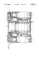
- FIG. 1is a view in perspective of an air compressor in accordance with the invention
- FIG. 2is a view in elevation of the air compressor of FIG. 1;
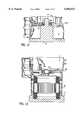
- FIG. 3is a view in vertical section through one end of the air compressor
- FIG. 4is a view in horizontal section taken in the plane of the line 4--4 of FIG. 3;
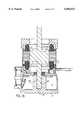
- FIG. 5is an enlarged view in section taken in the plane of the line 5--5 of FIG. 4;
- FIG. 6is an enlarged view in section taken in the plane of the line 6--6 in FIG. 4;
- FIG. 7is an enlarged view in section taken in the plane of the line 7--7 in FIG. 4;
- FIG. 8is an enlarged view in section taken in the plane of the line 8--8 in FIG. 4;
- FIG. 11is a top view in perspective of the one-piece head member.
- FIGS. 12 through 17are views in section which illustrate the steps of assembling the two-cylinder air compressor using press fits.
- the air compressorincludes a circular cylindrical thin wall spacer or sleeve 10 having perforations 11 adjacent its ends for purposes of air flow.
- the sleeve 10encircles an electric motor 12 having a through drive shaft 13.
- Identical end housings 14are joined to the motor sleeve 10.
- the housings 14are preferably formed of a cast material, such as aluminum.
- the housings 14include a circular flange 15 at one end that is machined with a rabbet or relief 16 that receives the end 9 of the motor sleeve 10, as shown in FIG. 3.
- the housings 14are formed with an internal bearing retainer portion 20 that is at the center of a series of spokes 21.
- the bearing retainer 20has a central bore 20a that mounts the outer race of a ball bearing 22 which receives the motor drive shaft 13.
- the bearing retainer 20 and spokes 21divide the housing into an outer enlarged cylindrical position 23 and an inner smaller cylindrical portion 24.
- the reduced diameter portion 24has a series of optional air openings 25 about its perimeter.
- a wobble piston 35is mounted on the projecting end of the motor shaft 13 outbound of the bearing 22 in a conventional manner. That is, an eccentric 36 is mounted to the shaft 13 and the piston 35 is mounted on the eccentric 36 with its axis offset from that of the motor drive shaft 13.
- the eccentric 36includes a counterweight 37.
- the piston head 38has a peripheral seal 39 formed of a Teflon cup. The seal 39 seals with the bore 40 of a cylinder sleeve 41.
- the cylinder sleeve 41is supported on a floor 45 in a cylinder extension 46 of the housing 14. As shown in FIG. 4, the floor 45 has an opening 47 to accommodate the piston 35 and the cylinder sleeve 41.
- the valve plate 54mounts an O-ring type seal 60 that seals against the top edge of the cylinder sleeve 41.
- the valve plate 54also includes an upper O-ring type seal 61 that seals with the bottom surface of a head portion 62 of a head member 63.
- the head member 63has head portions 62 at each end.
- the head portion 62are joined by an integral connector which includes spaced hollow tubes 64 and a web 65 joining the tubes 64.
- the hollow tubes 64connect to the inlet and exhaust chambers 67 and 68 of the head portions 62.
- the head portions 62are bolted to the bosses 52 of the cylinder extension 46 of the housings 14 by screws 69.
- the head portions 62also have openings 66 that are either open or plugged for external connections to the necessary piping to and from the chambers 67 and 68.
- the connector formed by the integral tubes 64 and web 65spans the distance between the head portions 62. As shown in FIG. 2, the tubes 64 and web 65 are spaced from the spacer 10 so that the connector can act as a handle or a hook for supporting the air compressor.
- the head member 63is also preferably formed of a cast aluminum.
- the construction of the compressor of this inventionlends itself to assembly without the use of bolts or screws. This is accomplished by using a press fit between the ends of the motor shell and the rabbets or reliefs 16 in the housings, by a press fit of the to the motor shaft, by a press fit between the bearings and the housing bores, and by the one-piece head.
- FIGS. 12 through 17The manner of assembling a boltless compressor is illustrated in FIGS. 12 through 17.
- the bearings 22are shown in stylized form.
- the assemblybegins by press fitting a bearing 22 into one of the housings 14a. This is accomplished using a fixture 70 having a land 71 which supports the outer side of the bearing retainer 20 adjacent its perimeter.
- the fixture 70has a central projection 72 which extends through the inner race of the bearing 22.
- the bearing 22is forced into the central bore 20a until it bottoms against a surface 73 which is disposed at a distance of a few hundredths of an inch from the land 71 against which the bearing retainer 20 rests.
- the one housing 14a with the bearing 22 in placeis then assembled to a motor stator and shell subassembly 74 using a further fixture 75, as shown in FIG. 13.
- the fixture 75supports the stator shell subassembly 74 while pressure is applied to the housing 14a to press fit the rabbet 16 of the housing 14a onto the motor shell 10.
- the housing 14a with the motor shell assembly 74 attachedis turned over and mounted in a further fixture 77 which has the same series of surfaces 78 and 79 as in the fixture 70.
- a guide 82is mounted on the opposite end of the shell 10.
- the guide 82has a central opening 83 which receives the motor shaft 13, as shown in FIG. 14.
- One end 13a of the motor shaft 13is forced through the bearing 22 mounted in the housing 14a with a press fit.
- the bottom position of the shaft 13 in the fixture 77is shown in FIG. 15.
- the bottom shaft positionis defined by the bottom 85 of a well 86 formed in the fixture 77. This action will also properly locate the rotor within the stator of the motor.
- second housing 14bis assembled to a bearing 22 in the same manner as illustrated in FIG. 12.
- the second housing 14b with its bearing 22is then inserted over the opposite end 13b of the motor shaft 13 as shown in FIG. 16.
- the second housing 14b with its bearing 22is forced over the end 13b of the motor shaft 13, and the rabbet 16 in the housing 14b engages with and is press fit onto the end 9 of the motor shell 10. In accomplishing this action, the bearing 22 in the second housing 14b is press fitted onto the motor shaft.
- the assemblyis complete by joining the two housings 14a and 14b with the one-piece head 63.
- the one-piece head 63is the principal attachment for the assembly because it requires the greatest load to completely separate the parts.
- the one-piece head 63also serves to keep the housings from rotating with respect to each other, which could happen during shipment.
- the press fits at the bearing jointssupply adequate motor to housing retention forces, but they cannot angularly align the housings with respect to each other.
- the motor shell to housing rabbet press fitsupplies another level of insurance to keep the parts together and oriented, particularly during the assembly process before the one-piece head is attached.
- the pressis set up to press on the second housing 14b and bearing 22 assembly while monitoring the press forces.
- the controls for the pressdetermine the point at which the housing rabbet bottoms against the motor shell 10 by measuring the change in slope of the force curve. When that bottoming occurs, the press keeps pressing until a certain differential force is added for bearing preload. The press then stops and retracts.
- the elimination of bolts and the use of cold pressing fitshas several advantages.
- the bearing clearancescan be tightened without causing assembly problems while at the same time helping to increase the housing retention forces.
- the elimination of the boltsreduces sound levels caused by bolt resonance. It also eliminates the opportunity for a bolt to touch the motor lamination and cause an annoying "buzz".
- Cold pressing without the use of boltseliminates the variability in the bearing preload caused by the bolt loads. Instead, the bearing preload is only affected by the pressing forces.
Landscapes
- Engineering & Computer Science (AREA)
- Mechanical Engineering (AREA)
- General Engineering & Computer Science (AREA)
- Compressors, Vaccum Pumps And Other Relevant Systems (AREA)
- Compressor (AREA)
- Reciprocating Pumps (AREA)
Abstract
Description
Claims (9)
Priority Applications (3)
| Application Number | Priority Date | Filing Date | Title |
|---|---|---|---|
| US09/199,123US6056521A (en) | 1996-06-28 | 1998-11-24 | Two-cylinder air compressor |
| US09/537,702US6227821B1 (en) | 1996-06-28 | 2000-03-28 | Two-cylinder pump |
| US09/813,676US6331101B2 (en) | 1996-06-28 | 2001-03-21 | Two-cylinder pump |
Applications Claiming Priority (2)
| Application Number | Priority Date | Filing Date | Title |
|---|---|---|---|
| US67184996A | 1996-06-28 | 1996-06-28 | |
| US09/199,123US6056521A (en) | 1996-06-28 | 1998-11-24 | Two-cylinder air compressor |
Related Parent Applications (1)
| Application Number | Title | Priority Date | Filing Date |
|---|---|---|---|
| US67184996AContinuation-In-Part | 1996-06-28 | 1996-06-28 |
Related Child Applications (1)
| Application Number | Title | Priority Date | Filing Date |
|---|---|---|---|
| US09/537,702ContinuationUS6227821B1 (en) | 1996-06-28 | 2000-03-28 | Two-cylinder pump |
Publications (1)
| Publication Number | Publication Date |
|---|---|
| US6056521Atrue US6056521A (en) | 2000-05-02 |
Family
ID=24696118
Family Applications (3)
| Application Number | Title | Priority Date | Filing Date |
|---|---|---|---|
| US09/199,123Expired - LifetimeUS6056521A (en) | 1996-06-28 | 1998-11-24 | Two-cylinder air compressor |
| US09/537,702Expired - LifetimeUS6227821B1 (en) | 1996-06-28 | 2000-03-28 | Two-cylinder pump |
| US09/813,676Expired - LifetimeUS6331101B2 (en) | 1996-06-28 | 2001-03-21 | Two-cylinder pump |
Family Applications After (2)
| Application Number | Title | Priority Date | Filing Date |
|---|---|---|---|
| US09/537,702Expired - LifetimeUS6227821B1 (en) | 1996-06-28 | 2000-03-28 | Two-cylinder pump |
| US09/813,676Expired - LifetimeUS6331101B2 (en) | 1996-06-28 | 2001-03-21 | Two-cylinder pump |
Country Status (5)
| Country | Link |
|---|---|
| US (3) | US6056521A (en) |
| JP (1) | JP3978256B2 (en) |
| DE (1) | DE19727185C2 (en) |
| GB (1) | GB2314593B (en) |
| IT (1) | IT1293387B1 (en) |
Cited By (38)
| Publication number | Priority date | Publication date | Assignee | Title |
|---|---|---|---|---|
| US6193475B1 (en)* | 1999-11-23 | 2001-02-27 | Thomas Industries Inc. | Compressor assembly |
| US6386833B1 (en)* | 2000-07-19 | 2002-05-14 | Campbell Hausfeld/Scott Fetzer Company | Air compressor assembly with dual cooling fans |
| US6431845B1 (en) | 2000-06-09 | 2002-08-13 | Gast Manufacturing, Inc. | Head cover assembly with monolithic valve plate |
| US6435076B2 (en) | 2000-07-19 | 2002-08-20 | Campbell Hausfeld/Scott Fetzer Cmopany | Air compressor assembly with bearing pocket |
| US6447257B2 (en)* | 2000-07-19 | 2002-09-10 | Campbell Hausfeld/Scott Fetzer Company | Air compressor assembly with vibration damping structure |
| WO2003016717A1 (en)* | 2001-08-13 | 2003-02-27 | Thomas Industries Inc. | Wobble piston pump with carbon graphite cylinder |
| US20040020233A1 (en)* | 2002-03-21 | 2004-02-05 | Ritchie Engineering Company, Inc. | Compressor head, internal discriminator, external discriminator, manifold design for refrigeration recovery apparatus |
| US6692240B1 (en)* | 1999-11-29 | 2004-02-17 | Thomas Industries Inc. | Cylindrical pump housing with a fan guard mounted on each end of the housing with snap tabs engaging housing recesses |
| US6779350B2 (en) | 2002-03-21 | 2004-08-24 | Ritchie Enginerring Company, Inc. | Compressor head, internal discriminator, external discriminator, manifold design for refrigerant recovery apparatus and vacuum sensor |
| USD499119S1 (en) | 2003-11-05 | 2004-11-30 | Gast Manufacturing Corporation | Compressor |
| US20050126200A1 (en)* | 2003-12-05 | 2005-06-16 | Ajit Ramachandran | Single valve manifold |
| US20050220637A1 (en)* | 2004-04-01 | 2005-10-06 | Hydro-Gear Limited Partnership | Fan shroud for pump |
| US20060045752A1 (en)* | 2004-08-30 | 2006-03-02 | Powermate Corporation | Air compressor tools that communicate with an air compressor |
| US20060045751A1 (en)* | 2004-08-30 | 2006-03-02 | Powermate Corporation | Air compressor with variable speed motor |
| US20060045749A1 (en)* | 2004-08-30 | 2006-03-02 | Powermate Corporation | Air compressor utilizing an electronic control system |
| US20060228242A1 (en)* | 2005-04-11 | 2006-10-12 | Ritchie Engineering Company, Inc. | Vacuum pump |
| US20060228246A1 (en)* | 2005-04-11 | 2006-10-12 | Ritchie Engineering Company, Inc. | Vacuum pump |
| USD532796S1 (en) | 2005-05-17 | 2006-11-28 | Thomas Industries, Inc. | Pump port |
| US20060275160A1 (en)* | 2005-05-17 | 2006-12-07 | Leu Shawn A | Pump improvements |
| US20070113575A1 (en)* | 2003-12-05 | 2007-05-24 | Ritchie Engineering Company, Inc. | Valve manifold assembly |
| US20070280838A1 (en)* | 2006-06-01 | 2007-12-06 | Gast Manufacturing, Inc. | Dual-cylinder rocking piston compressor |
| US20100074779A1 (en)* | 2006-09-08 | 2010-03-25 | Knorr-Bremse Systeme fuer Nutzfahhrzeuge GmbH | Air Compressor Having a Cast Aluminum Crankcase |
| USD648747S1 (en) | 2010-05-13 | 2011-11-15 | Airsep Corporation | Compressor end cap |
| USD684999S1 (en)* | 2012-01-10 | 2013-06-25 | Ulvac Kiko, Inc. | Vacuum pump |
| US9371865B1 (en) | 2008-08-01 | 2016-06-21 | Hydro-Gear Limited Partnership | Drive device |
| US20170335837A1 (en)* | 2014-11-10 | 2017-11-23 | Koninklijke Philips N.V. | Connector for a compressor assembly |
| US9856866B2 (en) | 2011-01-28 | 2018-01-02 | Wabtec Holding Corp. | Oil-free air compressor for rail vehicles |
| CN108894946A (en)* | 2018-08-31 | 2018-11-27 | 贵州佳能电机科技有限公司 | Double pump oxygenerator |
| USD875788S1 (en)* | 2018-11-05 | 2020-02-18 | EP Family Corp. | Air compressor |
| US10634129B1 (en) | 2019-10-14 | 2020-04-28 | Wood Industries Inc. | Dual motor compressor |
| CN114076080A (en)* | 2020-08-17 | 2022-02-22 | 江西杰豹机电有限公司 | A new type of oil-free piston air compressor |
| US11391133B2 (en) | 2011-04-07 | 2022-07-19 | Typhon Technology Solutions (U.S.), Llc | Dual pump VFD controlled motor electric fracturing system |
| WO2022212522A1 (en)* | 2021-03-31 | 2022-10-06 | Graco Minnesota Inc. | Cooling for an electrically operated displacement pump |
| US11613979B2 (en) | 2011-04-07 | 2023-03-28 | Typhon Technology Solutions, Llc | Mobile, modular, electrically powered system for use in fracturing underground formations using liquid petroleum gas |
| US11708752B2 (en) | 2011-04-07 | 2023-07-25 | Typhon Technology Solutions (U.S.), Llc | Multiple generator mobile electric powered fracturing system |
| WO2023215485A1 (en)* | 2022-05-04 | 2023-11-09 | Haptx, Inc. | Haptic glove system and manufacture of haptic glove systems |
| US11955782B1 (en) | 2022-11-01 | 2024-04-09 | Typhon Technology Solutions (U.S.), Llc | System and method for fracturing of underground formations using electric grid power |
| US12444910B2 (en) | 2024-03-25 | 2025-10-14 | Typhon Technology Solutions (U.S.), Llc | Method for accessing electric grids to power fracturing operations |
Families Citing this family (38)
| Publication number | Priority date | Publication date | Assignee | Title |
|---|---|---|---|---|
| US7284391B2 (en)* | 1998-10-06 | 2007-10-23 | Manitowoc Foodservice Companies, Inc. | Pump assembly for an ice making machine |
| JP4121209B2 (en)* | 1999-02-26 | 2008-07-23 | 東北リコー株式会社 | Paper feeding device in image forming apparatus |
| CA2392909C (en)* | 1999-11-29 | 2006-10-10 | Thomas Industries Inc. | Pump housing |
| US6485266B2 (en)* | 2000-03-10 | 2002-11-26 | Thomas Industries, Inc. | Compressor assembly with deflector |
| US6551077B2 (en)* | 2001-03-30 | 2003-04-22 | Wen San Chou | Air compressor having double pumping system |
| DE10143592C2 (en)* | 2001-09-05 | 2003-07-03 | Duerr Gmbh & Co Kg Luft Und Pr | Crankcase for a compressor |
| CN1711208A (en)* | 2002-11-04 | 2005-12-21 | 格雷索明尼苏达有限公司 | Fast set material proportioner |
| DE10255680B4 (en)* | 2002-11-28 | 2008-07-31 | Valeo Compressor Europe Gmbh | Axial piston compressors, in particular CO 2 compressors for vehicle air conditioning systems with split cylinder head |
| KR100454878B1 (en)* | 2002-11-28 | 2004-11-03 | 주식회사 케이오티씨 | An air compressor |
| USD488820S1 (en) | 2003-03-31 | 2004-04-20 | Thomas Industries Inc. | Pump |
| US20040253122A1 (en)* | 2003-06-10 | 2004-12-16 | Gary Grochowski | Endbell cylinder frame and housing for oil-free |
| US20060153705A1 (en)* | 2004-11-10 | 2006-07-13 | Horton W T | Drive shaft for compressor |
| JP2006233863A (en)* | 2005-02-24 | 2006-09-07 | Ngk Spark Plug Co Ltd | Compressor, vacuum pump and oxygen condenser |
| JP4149469B2 (en)* | 2005-07-04 | 2008-09-10 | 株式会社カワサキプレシジョンマシナリ | Pump unit casing and pump device including the same |
| CN102588249B (en)* | 2006-09-05 | 2015-01-21 | 嘉德纳丹佛托马斯公司 | Fluid intake and exhaust fittings for a compressor or pump |
| US8282363B2 (en)* | 2007-04-03 | 2012-10-09 | Techtronic Power Tools Technology Limited | Portable air compressor |
| JP5822181B2 (en)* | 2011-08-18 | 2015-11-24 | 日立工機株式会社 | air compressor |
| JP5898530B2 (en)* | 2012-03-02 | 2016-04-06 | カルソニックカンセイ株式会社 | Compressor seal structure |
| KR101602089B1 (en)* | 2012-03-30 | 2016-03-09 | 울박 키코 인코포레이션 | Pump device |
| JP6096474B2 (en)* | 2012-11-05 | 2017-03-15 | シナノケンシ株式会社 | Compressor or vacuum machine |
| US9863412B2 (en)* | 2012-11-28 | 2018-01-09 | Gast Manufacturing, Inc. | Rocking piston compressor with sound dissipation |
| KR101347675B1 (en)* | 2012-12-26 | 2014-01-03 | 서원콤프레샤주식회사 | Single and dual air compressor using halving housing |
| JP2015059504A (en)* | 2013-09-18 | 2015-03-30 | 日立工機株式会社 | air compressor |
| CN105298807B (en)* | 2015-11-21 | 2017-12-29 | 浙江鸿友压缩机制造有限公司 | A kind of fastening structure of air compressor cylinder lid and seat board |
| CN105508196B (en)* | 2016-01-22 | 2017-11-14 | 奉化市天风汽车空压机有限公司 | Piston type electric automobile air compressor |
| USD803270S1 (en)* | 2016-07-15 | 2017-11-21 | Chi-Wen Chen | Air compressor |
| CN106762550A (en)* | 2017-03-03 | 2017-05-31 | 浙江鸿友压缩机制造有限公司 | A kind of lightweight pump head mounting and the oil-free air compressor equipped with the pump head mounting |
| CN107143483A (en)* | 2017-06-24 | 2017-09-08 | 浙江永源机电制造有限公司 | A kind of oil-free twin-tub air compressor machine |
| CN107461314A (en)* | 2017-09-19 | 2017-12-12 | 浙江湖州大新能源科技有限公司 | A kind of internal-suction type is without oily piston brake air pump |
| WO2019148004A1 (en)* | 2018-01-26 | 2019-08-01 | Gardner Denver Thomas, Inc. | Pump with floating cylinders |
| USD883332S1 (en)* | 2018-02-19 | 2020-05-05 | Fiac S.P.A. | Air compressor |
| USD891479S1 (en)* | 2018-02-19 | 2020-07-28 | Fiac S.P.A. | Air compressor |
| TWI676736B (en)* | 2018-10-17 | 2019-11-11 | 中大冷凍材料股份有限公司 | Vacuum pumping structure |
| USD903720S1 (en)* | 2019-03-05 | 2020-12-01 | DÜRR Technik GmbH & Co. KG | Compressor |
| USD914062S1 (en)* | 2019-05-21 | 2021-03-23 | Ateliers François | Compressor part |
| US11319942B2 (en)* | 2019-07-19 | 2022-05-03 | Yu-Wen Lin | Compressor having heat dissipating structure |
| US11603833B2 (en)* | 2019-12-20 | 2023-03-14 | Arb Corporation Limited | Air compressors for use with a vehicle |
| USD1049171S1 (en) | 2024-07-15 | 2024-10-29 | Elias Brown | Dual-cylinder air compressor |
Citations (28)
| Publication number | Priority date | Publication date | Assignee | Title |
|---|---|---|---|---|
| US1126959A (en)* | 1912-03-26 | 1915-02-02 | Ingersoll Rand Co | Pulsator for pulsatory tools. |
| US1282482A (en)* | 1918-02-08 | 1918-10-22 | George Kinsel | Internal-combustion engine. |
| US3083308A (en)* | 1961-01-06 | 1963-03-26 | Gen Electric | Hermetic motor cartridge |
| US3094272A (en)* | 1960-12-09 | 1963-06-18 | Trane Co | Motor-compressor apparatus |
| US3158930A (en)* | 1961-05-01 | 1964-12-01 | Bendix Corp | Method of manufacturing assembly fluid pressure motors |
| US3664772A (en)* | 1970-09-04 | 1972-05-23 | Viktor Mitrushi Panariti | Fluid pump |
| US3865221A (en)* | 1974-01-09 | 1975-02-11 | Gen Motors Corp | Viscous fluid clutch |
| US3932070A (en)* | 1974-02-26 | 1976-01-13 | Ametek, Inc. | Electric motor fan unit for wet working air |
| US3961869A (en)* | 1974-09-26 | 1976-06-08 | Thomas Industries, Inc. | Air compressor |
| US3961868A (en)* | 1974-02-21 | 1976-06-08 | Thomas Industries, Inc. | Air compressor |
| US4017964A (en)* | 1974-10-12 | 1977-04-19 | Firma Schulte Elektrotechnik Kg | Method of manufacturing electrical machinery having a rotor |
| US4105374A (en)* | 1977-03-28 | 1978-08-08 | Copeland Corporation | Integrated multi-unit refrigeration motor-compressor assembly |
| GB1542926A (en)* | 1975-05-06 | 1979-03-28 | Itt | Integrated high capacity compressor |
| US4458405A (en)* | 1982-03-01 | 1984-07-10 | Clevepak Corporation | Method of assembling a motor bearing and seal in a motor |
| US4558992A (en)* | 1982-11-06 | 1985-12-17 | Mitsubishi Denki Kabushiki Kaisha | Pump device |
| US4584750A (en)* | 1984-02-28 | 1986-04-29 | Kabushiki Kaisha Toshiba | Enclosed type compressor and method for assembling the same |
| US4810174A (en)* | 1986-12-12 | 1989-03-07 | Flint & Walling, Inc. | Motor and pump assembly |
| US4834626A (en)* | 1986-08-01 | 1989-05-30 | Taer S.R.L. | Perfected portable motor-driven compressor set |
| US4958990A (en)* | 1989-09-29 | 1990-09-25 | General Electric Company | Motor-compressor with means to reduce noise |
| US5006047A (en)* | 1989-02-27 | 1991-04-09 | Thomas Industries, Inc. | Compressor with a segmented piston rod assembly |
| US5033941A (en)* | 1990-02-27 | 1991-07-23 | American Standard Inc. | Method for assembling rotors without fixtures |
| US5203071A (en)* | 1990-11-05 | 1993-04-20 | Ryobi Motor Products Corp. | Method of motor construction |
| US5228196A (en)* | 1990-10-04 | 1993-07-20 | Mitsubishi Denki Kabushiki Kaisha | Method for preparing a scroll compressor |
| US5246356A (en)* | 1992-12-10 | 1993-09-21 | Carrier Corporation | Sound abatement in rotary compressors |
| US5326233A (en)* | 1992-07-03 | 1994-07-05 | Mitsubishi Denki Kabushiki Kaisha | Enclosed motor compressor of a two cylinder type |
| DE29508399U1 (en)* | 1994-08-03 | 1995-07-20 | Siemens AG, 80333 München | Compressor unit |
| JPH07310651A (en)* | 1994-05-17 | 1995-11-28 | Toshiba Seiki Kk | Reciprocating pump unit |
| US5584675A (en)* | 1995-09-15 | 1996-12-17 | Devilbiss Air Power Company | Cylinder sleeve for an air compressor |
Family Cites Families (6)
| Publication number | Priority date | Publication date | Assignee | Title |
|---|---|---|---|---|
| US4663979A (en)* | 1986-01-21 | 1987-05-12 | General Motors Corporation | Solenoid attachment for electric starting apparatus |
| US5493158A (en)* | 1993-10-04 | 1996-02-20 | Emerson Electric Co. | Motor capacitor bracket |
| USD379996S (en)* | 1996-02-12 | 1997-06-17 | Thomas Industries, Inc. | Air compressor |
| US6126410A (en)* | 1998-02-12 | 2000-10-03 | Gast Manufacturing Corporation | Head cover assembly for reciprocating compressor |
| USD412174S (en)* | 1998-03-04 | 1999-07-20 | Faulkner Edward T | Compressor |
| USD405455S (en)* | 1998-07-01 | 1999-02-09 | Thomas Industries, Inc. | Air compressor |
- 1997
- 1997-06-18GBGB9712915Apatent/GB2314593B/ennot_activeExpired - Lifetime
- 1997-06-25ITIT97TO000554Apatent/IT1293387B1/enactiveIP Right Grant
- 1997-06-26DEDE19727185Apatent/DE19727185C2/ennot_activeExpired - Lifetime
- 1997-06-27JPJP17188097Apatent/JP3978256B2/ennot_activeExpired - Lifetime
- 1998
- 1998-11-24USUS09/199,123patent/US6056521A/ennot_activeExpired - Lifetime
- 2000
- 2000-03-28USUS09/537,702patent/US6227821B1/ennot_activeExpired - Lifetime
- 2001
- 2001-03-21USUS09/813,676patent/US6331101B2/ennot_activeExpired - Lifetime
Patent Citations (28)
| Publication number | Priority date | Publication date | Assignee | Title |
|---|---|---|---|---|
| US1126959A (en)* | 1912-03-26 | 1915-02-02 | Ingersoll Rand Co | Pulsator for pulsatory tools. |
| US1282482A (en)* | 1918-02-08 | 1918-10-22 | George Kinsel | Internal-combustion engine. |
| US3094272A (en)* | 1960-12-09 | 1963-06-18 | Trane Co | Motor-compressor apparatus |
| US3083308A (en)* | 1961-01-06 | 1963-03-26 | Gen Electric | Hermetic motor cartridge |
| US3158930A (en)* | 1961-05-01 | 1964-12-01 | Bendix Corp | Method of manufacturing assembly fluid pressure motors |
| US3664772A (en)* | 1970-09-04 | 1972-05-23 | Viktor Mitrushi Panariti | Fluid pump |
| US3865221A (en)* | 1974-01-09 | 1975-02-11 | Gen Motors Corp | Viscous fluid clutch |
| US3961868A (en)* | 1974-02-21 | 1976-06-08 | Thomas Industries, Inc. | Air compressor |
| US3932070A (en)* | 1974-02-26 | 1976-01-13 | Ametek, Inc. | Electric motor fan unit for wet working air |
| US3961869A (en)* | 1974-09-26 | 1976-06-08 | Thomas Industries, Inc. | Air compressor |
| US4017964A (en)* | 1974-10-12 | 1977-04-19 | Firma Schulte Elektrotechnik Kg | Method of manufacturing electrical machinery having a rotor |
| GB1542926A (en)* | 1975-05-06 | 1979-03-28 | Itt | Integrated high capacity compressor |
| US4105374A (en)* | 1977-03-28 | 1978-08-08 | Copeland Corporation | Integrated multi-unit refrigeration motor-compressor assembly |
| US4458405A (en)* | 1982-03-01 | 1984-07-10 | Clevepak Corporation | Method of assembling a motor bearing and seal in a motor |
| US4558992A (en)* | 1982-11-06 | 1985-12-17 | Mitsubishi Denki Kabushiki Kaisha | Pump device |
| US4584750A (en)* | 1984-02-28 | 1986-04-29 | Kabushiki Kaisha Toshiba | Enclosed type compressor and method for assembling the same |
| US4834626A (en)* | 1986-08-01 | 1989-05-30 | Taer S.R.L. | Perfected portable motor-driven compressor set |
| US4810174A (en)* | 1986-12-12 | 1989-03-07 | Flint & Walling, Inc. | Motor and pump assembly |
| US5006047A (en)* | 1989-02-27 | 1991-04-09 | Thomas Industries, Inc. | Compressor with a segmented piston rod assembly |
| US4958990A (en)* | 1989-09-29 | 1990-09-25 | General Electric Company | Motor-compressor with means to reduce noise |
| US5033941A (en)* | 1990-02-27 | 1991-07-23 | American Standard Inc. | Method for assembling rotors without fixtures |
| US5228196A (en)* | 1990-10-04 | 1993-07-20 | Mitsubishi Denki Kabushiki Kaisha | Method for preparing a scroll compressor |
| US5203071A (en)* | 1990-11-05 | 1993-04-20 | Ryobi Motor Products Corp. | Method of motor construction |
| US5326233A (en)* | 1992-07-03 | 1994-07-05 | Mitsubishi Denki Kabushiki Kaisha | Enclosed motor compressor of a two cylinder type |
| US5246356A (en)* | 1992-12-10 | 1993-09-21 | Carrier Corporation | Sound abatement in rotary compressors |
| JPH07310651A (en)* | 1994-05-17 | 1995-11-28 | Toshiba Seiki Kk | Reciprocating pump unit |
| DE29508399U1 (en)* | 1994-08-03 | 1995-07-20 | Siemens AG, 80333 München | Compressor unit |
| US5584675A (en)* | 1995-09-15 | 1996-12-17 | Devilbiss Air Power Company | Cylinder sleeve for an air compressor |
Non-Patent Citations (4)
| Title |
|---|
| Joseph Shigley, Mechanical Engineering Design, 3rd Ed., McGraw Hill, pp. 63 65, 1977.* |
| Joseph Shigley, Mechanical Engineering Design, 3rd Ed., McGraw-Hill, pp. 63-65, 1977. |
| Thomas Compressor Pump, Field Service Manual, 2619CGH147 932, Thomas Industries, Inc., 1996.* |
| Thomas Compressor Pump, Field Service Manual, 2619CGH147-932, Thomas Industries, Inc., 1996. |
Cited By (69)
| Publication number | Priority date | Publication date | Assignee | Title |
|---|---|---|---|---|
| US6193475B1 (en)* | 1999-11-23 | 2001-02-27 | Thomas Industries Inc. | Compressor assembly |
| US6692240B1 (en)* | 1999-11-29 | 2004-02-17 | Thomas Industries Inc. | Cylindrical pump housing with a fan guard mounted on each end of the housing with snap tabs engaging housing recesses |
| US6431845B1 (en) | 2000-06-09 | 2002-08-13 | Gast Manufacturing, Inc. | Head cover assembly with monolithic valve plate |
| US6386833B1 (en)* | 2000-07-19 | 2002-05-14 | Campbell Hausfeld/Scott Fetzer Company | Air compressor assembly with dual cooling fans |
| US6435076B2 (en) | 2000-07-19 | 2002-08-20 | Campbell Hausfeld/Scott Fetzer Cmopany | Air compressor assembly with bearing pocket |
| US6447257B2 (en)* | 2000-07-19 | 2002-09-10 | Campbell Hausfeld/Scott Fetzer Company | Air compressor assembly with vibration damping structure |
| US20050002805A1 (en)* | 2001-08-13 | 2005-01-06 | Fuksa Richard C | Wobble piston pump with carbon graphite cylinder |
| WO2003016717A1 (en)* | 2001-08-13 | 2003-02-27 | Thomas Industries Inc. | Wobble piston pump with carbon graphite cylinder |
| US20050076718A1 (en)* | 2002-03-21 | 2005-04-14 | Ajit Ramachandran | Compressor head, internal discriminator, external discriminator, manifold design for refrigerant recovery apparatus and vacuum sensor |
| US7428822B2 (en) | 2002-03-21 | 2008-09-30 | Ritchie Engineering Company, Inc. | Vacuum sensor |
| US6832491B2 (en) | 2002-03-21 | 2004-12-21 | Ritchie Engineering Company, Inc. | Compressor head, internal discriminator, external discriminator, manifold design for refrigerant recovery apparatus |
| US6779350B2 (en) | 2002-03-21 | 2004-08-24 | Ritchie Enginerring Company, Inc. | Compressor head, internal discriminator, external discriminator, manifold design for refrigerant recovery apparatus and vacuum sensor |
| US7159412B2 (en) | 2002-03-21 | 2007-01-09 | Ritchie Engineering Company, Inc. | Compressor head, internal discriminator, external discriminator, manifold design for refrigeration recovery apparatus |
| US20050092010A1 (en)* | 2002-03-21 | 2005-05-05 | Ritchie Engineering Company, Inc. | Compressor head, internal discriminator, external discriminator, manifold design for refrigeration recovery apparatus |
| US20070017244A1 (en)* | 2002-03-21 | 2007-01-25 | Ritchie Engineering Company, Inc. | Compressor head, internal discriminator, external discriminator, manifold design for refrigerant recovery apparatus and vacuum sensor |
| US7310965B2 (en) | 2002-03-21 | 2007-12-25 | Ritchie Engineering Company, Inc. | Compressor head, internal discriminator, external discriminator, manifold design for refrigeration recovery apparatus |
| US20060032257A1 (en)* | 2002-03-21 | 2006-02-16 | Ajit Ramachandran | Compressor head, internal discriminator, external discriminator, manifold design for refrigeration recovery apparatus |
| US7073346B2 (en) | 2002-03-21 | 2006-07-11 | Ritchie Engineering Company, Inc. | Compressor head, internal discriminator, external discriminator, manifold design for refrigerant recovery apparatus and vacuum sensor |
| US20040020233A1 (en)* | 2002-03-21 | 2004-02-05 | Ritchie Engineering Company, Inc. | Compressor head, internal discriminator, external discriminator, manifold design for refrigeration recovery apparatus |
| USD499119S1 (en) | 2003-11-05 | 2004-11-30 | Gast Manufacturing Corporation | Compressor |
| US20070113575A1 (en)* | 2003-12-05 | 2007-05-24 | Ritchie Engineering Company, Inc. | Valve manifold assembly |
| US20050126200A1 (en)* | 2003-12-05 | 2005-06-16 | Ajit Ramachandran | Single valve manifold |
| US8858198B1 (en) | 2004-04-01 | 2014-10-14 | Hydro-Gear Limited Partnership | Fan shroud for pump |
| US9181958B1 (en) | 2004-04-01 | 2015-11-10 | Hydro-Gear Limited Partnership | Fan shroud for pump |
| US20050220637A1 (en)* | 2004-04-01 | 2005-10-06 | Hydro-Gear Limited Partnership | Fan shroud for pump |
| US7481627B2 (en) | 2004-08-30 | 2009-01-27 | Mat Industries Llc | Air compressor tools that communicate with an air compressor |
| US7789102B2 (en) | 2004-08-30 | 2010-09-07 | Mat Industries Llc | Air compressor having a pneumatic controller for controlling output air pressure |
| US20060045752A1 (en)* | 2004-08-30 | 2006-03-02 | Powermate Corporation | Air compressor tools that communicate with an air compressor |
| US20060045751A1 (en)* | 2004-08-30 | 2006-03-02 | Powermate Corporation | Air compressor with variable speed motor |
| US20060045749A1 (en)* | 2004-08-30 | 2006-03-02 | Powermate Corporation | Air compressor utilizing an electronic control system |
| US20080069703A1 (en)* | 2004-08-30 | 2008-03-20 | Powermate Corporation | Air compressor having a pneumatic controller for controlling output air pressure |
| US20080069708A1 (en)* | 2004-08-30 | 2008-03-20 | Powermate Corporation | Air compressor utilizing a variable speed motor and an electronic control system |
| US20060228246A1 (en)* | 2005-04-11 | 2006-10-12 | Ritchie Engineering Company, Inc. | Vacuum pump |
| US20060228242A1 (en)* | 2005-04-11 | 2006-10-12 | Ritchie Engineering Company, Inc. | Vacuum pump |
| US20060275160A1 (en)* | 2005-05-17 | 2006-12-07 | Leu Shawn A | Pump improvements |
| GB2426556B (en)* | 2005-05-17 | 2010-06-09 | Thomas Industries Inc | Pump improvements |
| USD532796S1 (en) | 2005-05-17 | 2006-11-28 | Thomas Industries, Inc. | Pump port |
| US9074589B2 (en) | 2005-05-17 | 2015-07-07 | Thomas Industries, Inc. | Pump |
| WO2007143241A1 (en)* | 2006-06-01 | 2007-12-13 | Gast Manufacturing, Inc. | Dual-clyinder rocking piston compressor |
| JP2009539029A (en)* | 2006-06-01 | 2009-11-12 | ガスト マニュファクチャリング インコーポレイテッド | Dual cylinder swing piston compressor |
| US20070280838A1 (en)* | 2006-06-01 | 2007-12-06 | Gast Manufacturing, Inc. | Dual-cylinder rocking piston compressor |
| CN101479475B (en)* | 2006-06-01 | 2011-02-09 | 盖斯特制造公司 | Twin-cylinder rocking piston compressor |
| US8246327B2 (en) | 2006-06-01 | 2012-08-21 | Gast Manufacturing, Inc. | Dual-cylinder rocking piston compressor |
| US20100074779A1 (en)* | 2006-09-08 | 2010-03-25 | Knorr-Bremse Systeme fuer Nutzfahhrzeuge GmbH | Air Compressor Having a Cast Aluminum Crankcase |
| US8371828B2 (en) | 2006-09-08 | 2013-02-12 | Knorr-Bremse Systeme Fuer Nutzfahrzeuge Gmbh | Air compressor having a cast aluminum crankcase |
| US9371865B1 (en) | 2008-08-01 | 2016-06-21 | Hydro-Gear Limited Partnership | Drive device |
| US10480142B1 (en) | 2008-08-01 | 2019-11-19 | Hydro-Gear Limited Partnership | Drive device |
| USD648747S1 (en) | 2010-05-13 | 2011-11-15 | Airsep Corporation | Compressor end cap |
| US9856866B2 (en) | 2011-01-28 | 2018-01-02 | Wabtec Holding Corp. | Oil-free air compressor for rail vehicles |
| US11391133B2 (en) | 2011-04-07 | 2022-07-19 | Typhon Technology Solutions (U.S.), Llc | Dual pump VFD controlled motor electric fracturing system |
| US12258847B2 (en) | 2011-04-07 | 2025-03-25 | Typhon Technology Solutions (U.S.), Llc | Fracturing blender system and method |
| US11939852B2 (en) | 2011-04-07 | 2024-03-26 | Typhon Technology Solutions (U.S.), Llc | Dual pump VFD controlled motor electric fracturing system |
| US11913315B2 (en) | 2011-04-07 | 2024-02-27 | Typhon Technology Solutions (U.S.), Llc | Fracturing blender system and method using liquid petroleum gas |
| US11613979B2 (en) | 2011-04-07 | 2023-03-28 | Typhon Technology Solutions, Llc | Mobile, modular, electrically powered system for use in fracturing underground formations using liquid petroleum gas |
| US11391136B2 (en) | 2011-04-07 | 2022-07-19 | Typhon Technology Solutions (U.S.), Llc | Dual pump VFD controlled motor electric fracturing system |
| US11851998B2 (en) | 2011-04-07 | 2023-12-26 | Typhon Technology Solutions (U.S.), Llc | Dual pump VFD controlled motor electric fracturing system |
| US11708752B2 (en) | 2011-04-07 | 2023-07-25 | Typhon Technology Solutions (U.S.), Llc | Multiple generator mobile electric powered fracturing system |
| USD684999S1 (en)* | 2012-01-10 | 2013-06-25 | Ulvac Kiko, Inc. | Vacuum pump |
| US20170335837A1 (en)* | 2014-11-10 | 2017-11-23 | Koninklijke Philips N.V. | Connector for a compressor assembly |
| US10578086B2 (en)* | 2014-11-10 | 2020-03-03 | Koninklijke Philips N.V. | Connector for a compressor assembly |
| CN108894946A (en)* | 2018-08-31 | 2018-11-27 | 贵州佳能电机科技有限公司 | Double pump oxygenerator |
| USD875788S1 (en)* | 2018-11-05 | 2020-02-18 | EP Family Corp. | Air compressor |
| US11499538B2 (en) | 2019-10-14 | 2022-11-15 | Wood Industries Inc. | Dual motor compressor |
| US10634129B1 (en) | 2019-10-14 | 2020-04-28 | Wood Industries Inc. | Dual motor compressor |
| CN114076080A (en)* | 2020-08-17 | 2022-02-22 | 江西杰豹机电有限公司 | A new type of oil-free piston air compressor |
| WO2022212522A1 (en)* | 2021-03-31 | 2022-10-06 | Graco Minnesota Inc. | Cooling for an electrically operated displacement pump |
| WO2023215485A1 (en)* | 2022-05-04 | 2023-11-09 | Haptx, Inc. | Haptic glove system and manufacture of haptic glove systems |
| US11955782B1 (en) | 2022-11-01 | 2024-04-09 | Typhon Technology Solutions (U.S.), Llc | System and method for fracturing of underground formations using electric grid power |
| US12444910B2 (en) | 2024-03-25 | 2025-10-14 | Typhon Technology Solutions (U.S.), Llc | Method for accessing electric grids to power fracturing operations |
Also Published As
| Publication number | Publication date |
|---|---|
| US6331101B2 (en) | 2001-12-18 |
| GB2314593B (en) | 1999-11-10 |
| GB2314593A (en) | 1998-01-07 |
| JPH10115283A (en) | 1998-05-06 |
| ITTO970554A1 (en) | 1998-12-25 |
| DE19727185A1 (en) | 1998-02-12 |
| US6227821B1 (en) | 2001-05-08 |
| ITTO970554A0 (en) | 1997-06-25 |
| DE19727185C2 (en) | 2002-11-28 |
| GB9712915D0 (en) | 1997-08-20 |
| IT1293387B1 (en) | 1999-03-01 |
| US20010009646A1 (en) | 2001-07-26 |
| JP3978256B2 (en) | 2007-09-19 |
Similar Documents
| Publication | Publication Date | Title |
|---|---|---|
| US6056521A (en) | Two-cylinder air compressor | |
| US9074589B2 (en) | Pump | |
| CA1330977C (en) | High side scotch yoke compressor with motor cooled by discharge gas | |
| KR20040089486A (en) | Reciprocating compressor | |
| US20050100458A1 (en) | Pump with transfer tube | |
| CA1330975C (en) | Arterial discharge muffler chambers in a driven piston compressor | |
| US4547131A (en) | Refrigeration compressor and method of assembling same | |
| EP1327076B1 (en) | Diaphragm pump with support ring | |
| US6886523B2 (en) | Engine and pump assembly having combined housing | |
| CA1330786C (en) | Suction line adaptor and filter | |
| JPH0684751B2 (en) | Refrigeration compressor | |
| JPH09264254A (en) | Piston type compressor and assembling method thereof | |
| US20060153705A1 (en) | Drive shaft for compressor | |
| KR850000351B1 (en) | Split crankcase radial automotive compressor |
Legal Events
| Date | Code | Title | Description |
|---|---|---|---|
| AS | Assignment | Owner name:THOMAS INDUSTRIES, INC., WISCONSIN Free format text:ASSIGNMENT OF ASSIGNORS INTEREST;ASSIGNORS:LEU, SHAWN A.;BERGNER, JEFFREY W.;MESCHLER, GREGG E.;AND OTHERS;REEL/FRAME:009615/0586 Effective date:19981112 | |
| STCF | Information on status: patent grant | Free format text:PATENTED CASE | |
| FPAY | Fee payment | Year of fee payment:4 | |
| FPAY | Fee payment | Year of fee payment:8 | |
| FPAY | Fee payment | Year of fee payment:12 | |
| AS | Assignment | Owner name:UBS AG, STAMFORD BRANCH. AS COLLATERAL AGENT, CONN Free format text:SECURITY AGREEMENT;ASSIGNORS:GARDNER DENVER THOMAS, INC.;GARDNER DENVER NASH, LLC;GARDNER DENVER, INC.;AND OTHERS;REEL/FRAME:030982/0767 Effective date:20130805 | |
| AS | Assignment | Owner name:CITIBANK, N.A., AS ADMINISTRATIVE AND COLLATERAL A Free format text:ASSIGNMENT OF PATENT SECURITY INTEREST;ASSIGNOR:UBS AG, STAMFORD BRANCH;REEL/FRAME:049738/0387 Effective date:20190628 | |
| AS | Assignment | Owner name:THOMAS INDUSTRIES INC., WISCONSIN Free format text:RELEASE OF PATENT SECURITY INTEREST;ASSIGNOR:CITIBANK, N.A., AS COLLATERAL AGENT;REEL/FRAME:067401/0879 Effective date:20240510 Owner name:LEROI INTERNATIONAL, INC., WISCONSIN Free format text:RELEASE OF PATENT SECURITY INTEREST;ASSIGNOR:CITIBANK, N.A., AS COLLATERAL AGENT;REEL/FRAME:067401/0879 Effective date:20240510 Owner name:GARDNER DENVER WATER JETTING SYSTEMS, INC., ILLINOIS Free format text:RELEASE OF PATENT SECURITY INTEREST;ASSIGNOR:CITIBANK, N.A., AS COLLATERAL AGENT;REEL/FRAME:067401/0879 Effective date:20240510 Owner name:GARDNER DENVER THOMAS, INC., WISCONSIN Free format text:RELEASE OF PATENT SECURITY INTEREST;ASSIGNOR:CITIBANK, N.A., AS COLLATERAL AGENT;REEL/FRAME:067401/0879 Effective date:20240510 Owner name:GARDNER DENVER NASH LLC, PENNSYLVANIA Free format text:RELEASE OF PATENT SECURITY INTEREST;ASSIGNOR:CITIBANK, N.A., AS COLLATERAL AGENT;REEL/FRAME:067401/0879 Effective date:20240510 Owner name:INDUSTRIAL TECHNOLOGIES AND SERVICES, LLC, NORTH CAROLINA Free format text:RELEASE OF PATENT SECURITY INTEREST;ASSIGNOR:CITIBANK, N.A., AS COLLATERAL AGENT;REEL/FRAME:067401/0879 Effective date:20240510 |