US6056281A - Adjustable stoppers and mounting assemblies for parts grippers - Google Patents
Adjustable stoppers and mounting assemblies for parts grippersDownload PDFInfo
- Publication number
- US6056281A US6056281AUS09/199,957US19995798AUS6056281AUS 6056281 AUS6056281 AUS 6056281AUS 19995798 AUS19995798 AUS 19995798AUS 6056281 AUS6056281 AUS 6056281A
- Authority
- US
- United States
- Prior art keywords
- jaw members
- stopper
- opposed jaw
- workpiece holder
- holder according
- Prior art date
- Legal status (The legal status is an assumption and is not a legal conclusion. Google has not performed a legal analysis and makes no representation as to the accuracy of the status listed.)
- Expired - Lifetime
Links
Images


Classifications
- B—PERFORMING OPERATIONS; TRANSPORTING
- B25—HAND TOOLS; PORTABLE POWER-DRIVEN TOOLS; MANIPULATORS
- B25B—TOOLS OR BENCH DEVICES NOT OTHERWISE PROVIDED FOR, FOR FASTENING, CONNECTING, DISENGAGING OR HOLDING
- B25B5/00—Clamps
- B25B5/06—Arrangements for positively actuating jaws
- B25B5/08—Arrangements for positively actuating jaws using cams
- B25B5/087—Arrangements for positively actuating jaws using cams actuated by a hydraulic or pneumatic piston
- B—PERFORMING OPERATIONS; TRANSPORTING
- B25—HAND TOOLS; PORTABLE POWER-DRIVEN TOOLS; MANIPULATORS
- B25B—TOOLS OR BENCH DEVICES NOT OTHERWISE PROVIDED FOR, FOR FASTENING, CONNECTING, DISENGAGING OR HOLDING
- B25B5/00—Clamps
- B25B5/16—Details, e.g. jaws, jaw attachments
- B25B5/163—Jaws or jaw attachments
- B—PERFORMING OPERATIONS; TRANSPORTING
- B25—HAND TOOLS; PORTABLE POWER-DRIVEN TOOLS; MANIPULATORS
- B25J—MANIPULATORS; CHAMBERS PROVIDED WITH MANIPULATION DEVICES
- B25J15/00—Gripping heads and other end effectors
- B25J15/0052—Gripping heads and other end effectors multiple gripper units or multiple end effectors
- B—PERFORMING OPERATIONS; TRANSPORTING
- B25—HAND TOOLS; PORTABLE POWER-DRIVEN TOOLS; MANIPULATORS
- B25J—MANIPULATORS; CHAMBERS PROVIDED WITH MANIPULATION DEVICES
- B25J15/00—Gripping heads and other end effectors
- B25J15/02—Gripping heads and other end effectors servo-actuated
- B25J15/0206—Gripping heads and other end effectors servo-actuated comprising articulated grippers
- B25J15/0226—Gripping heads and other end effectors servo-actuated comprising articulated grippers actuated by cams
- B—PERFORMING OPERATIONS; TRANSPORTING
- B25—HAND TOOLS; PORTABLE POWER-DRIVEN TOOLS; MANIPULATORS
- B25J—MANIPULATORS; CHAMBERS PROVIDED WITH MANIPULATION DEVICES
- B25J15/00—Gripping heads and other end effectors
- B25J15/04—Gripping heads and other end effectors with provision for the remote detachment or exchange of the head or parts thereof
- B25J15/0475—Exchangeable fingers
- B—PERFORMING OPERATIONS; TRANSPORTING
- B25—HAND TOOLS; PORTABLE POWER-DRIVEN TOOLS; MANIPULATORS
- B25J—MANIPULATORS; CHAMBERS PROVIDED WITH MANIPULATION DEVICES
- B25J9/00—Programme-controlled manipulators
- B25J9/08—Programme-controlled manipulators characterised by modular constructions
Definitions
- the present inventionrelates to fluid pressure actuated grippers of the type employed in automated workpiece handling devices which clampingly grip and transfer workpieces from one station to another. More particularly, the present invention relates to adjustable stoppers and mounting assemblies for fluid pressure actuated grippers.
- Fluid pressure actuated grippersare widely employed and typically take the form of a pneumatic or hydraulic differential motor whose cylinder is fixedly mounted to a transfer device.
- a gripper jaw mounting structureis fixedly mounted on the cylinder to pivotally support a pair of opposed gripper jaws which are coupled to the piston rod of the motor by a linkage so arranged that upon movement of the piston in one direction the jaws are pivoted to an open position and upon movement of the piston in the opposite direction the jaws are driven to a closed workpiece gripping position.
- the gripper jawswill be closed upon a workpiece near the edge of the workpiece and the gripper will be advanced to position the gripped workpiece in operative relationship with a work station.
- the gripperwill then be opened to release the workpiece and the transfer device will retract the gripper from the work station while the work operation is performed.
- the gripperwill then advance back into the work station and the jaws will again close upon the workpiece and carry it away from the work station. Opening and closing the gripper jaws thus takes place when the gripper is in its closest proximity to tooling at the work station.
- pivotable link arrangementsused in fluid pressure actuated grippers to connect the gripper jaws to the piston rods and effect movement of the gripper jaws.
- pivotable link arrangementsand pivotal cam arrangements.
- An example of a pivotal link arrangementcan be found in U.S. Pat. No. 5,152,568 to Blatt which discloses pivotal links 36 and 40 that cooperate with gripper jaws 12A and 12B as shown in FIG. 3.
- U.S. Pat. No. 4,518,187 to Blatt et al.discloses a pivotal cam arrangement in which jaw plates 45 and 47 are pivoted by the cooperation of cam slots 61 provided in the jaw plates and a pivot pin 37 (and rollers 39) attached to the piston rod.
- Fluid pressure actuated grippersare generally designed for use with particular workpieces to be transferred and with specific work stations. For example, some workpieces and/or work stations may require wider or narrower gripper jaws, different types of gripper jaws, gripper jaws that open at different angles, different clearance requirements, etc. Some work stations may provide restricted access clearance and thus impose limits on the degree to which gripper jaws open. Because of the wide variety of design or performance options required of grippers, manufacturing facilities which utilize fluid actuated grippers typically have numerous sets of grippers which are designed to transport different workpieces between specific work stations. The requirement of stocking multiple sets of grippers adds to the manufacturer's costs.
- the present inventionis directed to adjustable stoppers and mounting assemblies for fluid pressure actuated grippers which allow more versatility for using the grippers with different workpieces and work stations.
- the present inventionprovides a workpiece holder which includes:
- a stopperwhich is removably coupled to one of the pair of jaw members and positioned to contact the other of the pair of jaw members so as to limit the angle at which the pair of jaw members are opened by the actuator.
- the present inventionfurther provides a mounting assembly for a workpiece holder which includes:
- a mounting platehaving a partial spherical shaped bore therein;
- a clamping platehaving a partial spherical shaped bore therein;
- a spherical collarhaving a central through bore positioned between the mounting plate and clamping plate;
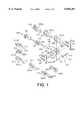
- FIG. 1is an exploded prospective view which depicts components of a modular gripper according to the present invention.
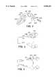
- FIG. 2is a perspective view of an adjustable stopper assembly according to one embodiment of the present invention.
- FIG. 3is a side view of a parts gripper having the adjustable stopper of FIG. 2 installed on one of the jaw members.
- FIG. 4is a side view of the parts gripper of FIG. 3 having the adjustable stopper installed in a different location on one of the jaw members.
- FIG. 5is a perspective view of an adjustable stopper assembly according to another embodiment of the present invention which includes a reversible stopper.
- FIGS. 6a and 6bare side views of a parts griper having the reversible stopper of FIG. 5 installed on one of the jaw members.
- FIG. 7is an exploded perspective view of a mounting assemble according to one embodiment of the present invention.
- the present inventionis directed to fluid pressure actuated grippers of the type employed in automated workpiece handling devices which clampingly grip and transfer a workpiece from one station to another.
- the gripper devices of the present inventioninclude a pneumatic or hydraulic differential motor which drives a piston rod in a reciprocal fashion, and a pair of jaws which are attached to the piston rod by a mechanical linkage that effects opening and closing of the jaws as the piston rod undergoes reciprocal motion.
- the mechanical linkage which connects the gripper jaws to the piston rod and effects opening and closing of the jawsis a pivotal cam type linkage. That is, the gripper jaws include a cam slot which receives a cam pin that is attached to the piston rod. As the piston rod is moved in a reciprocal manner by the pneumatic or hydraulic differential motor, the cam pin slides through the cam slots causing the gripper jaws to open and close.
- the cam slotsare designed to have a particular shape which effects opening and closing of the gripper jaws, and which can further cause the gripper jaws to become locked in either or both a closed position or an open position. "Locked" in position means that the position of the jaws in a closed and/or open position cannot be easily changed except by normal fluid operation of the pneumatic or hydraulic differential motor.
- the present inventionis further directed to fluid pressure actuated grippers which are assembled from a plurality of modular or interchangeable components.
- the modular grippers of the present inventioninclude a common body having a yoke structure, a common piston assembly which moves in a reciprocal manner in the yoke structure, a cam pin coupled to the piston assembly, and a plurality of interchangeable components which can be assembled to the yoke structure and piston assembly to provide modular fluid pressure activated grippers having diverse performance characteristics.
- the interchangeable components of the modular grippersinclude gripper jaws, gripper tips, reversible gripper tips, pneumatic or hydraulic cylinder end closures or plugs, reversible pneumatic or hydraulic cylinder end closures or plugs, and side or impact plates.
- the present inventionis further directed to adjustable stoppers and mounting assemblies which can effect the versatility of the fluid pressure actuated grippers or other workpiece holders.
- the stoppersare designed to be removably attached to a pivotal jaw member so that they abut the opposed jaw member and limit the degree at which the jaw members are opened.
- the stoppersinclude a stop block which has an alignment structure that engages with a complementary alignment structure in a jaw member.
- the stoppersalso include one or more stopper pads which extend from the stop blocks.
- the stopper padsabut the opposing jaw member and are preferably made from a material such as urethane which can absorb shock.
- reversible stoppersincluding two or more stopper pads that have different lengths can be used to adjust the angle at which the jaw members open. Otherwise, the stoppers can be removed and replaced to adjust the angle at which the jaw members open.
- the mounting assembly of the present inventionincludes a spherical collar which is tightened between a mounting plate and a clamping plate.
- the mounting platecan be attached to the body of a parts gripper or other workpiece holder at the end or a side thereof.
- the spherical collarincludes a central bore which receives a cylindrical support member. Tightening the clamping plate toward the mounting plate causes the spherical collar to be clamped onto the cylindrical support member.
- the clamping plateincludes a circular bore through which the cylindrical support member is passed as it is inserted into the spherical collar. This circular bore is large enough and can further be beveled to allow adjustable angular orientation of the cylindrical support member with respect to the gripper body.
- the mounting platecan include a circular bore which is approximately the same size as the cylindrical support member. This circular bore allows the cylindrical support member to be easily axially aligned with the gripper body, by merely inserting the cylindrical support member through the spherical collar and into or through the circular bore in the mounting plate.
- FIG. 1is an exploded view which depicts the components of a modular gripper according to the present invention.
- the "common elements" of this gripperinclude the body 101, the piston assembly 102, jaw pivot pin 105 and the jaw driver assembly.
- the piston assembly 102includes piston 106, piston seal 107, piston shaft 108, and piston shaft seal 109.
- the jaw driver assemblyincludes cross piece 110 which is attached to piston shaft 108, cam pin 111 which is coupled to cross piece 110, and jaw bushings 112 which are received in cam slots 103 of the jaw members 100 and slider bushings 113 which are received in longitudinal slots 114 formed in the side walls of the yoke structure of the body 101.
- common elementsreferred to above is used to identify the basic elements of a modular gripper to which numerous interchangeable parts or elements can be attached or assembled.
- the “common elements”include the gripper body and the mechanical elements which are used to drive the gripper jaws.
- FIG. 1depicts a number of different interchangeable gripper jaws 100a to 100i which can be assembled in the body 101 and coupled to the jaw driver assembly 102.
- each of the different jaws 100a to 100ihave different tip end designs and/or cam slots 100b that effect different movement characteristics.
- the modular gripper of the present inventioncan be assembled to include gripper jaws having different tip designs that can be used for handling, e.g., transporting or transferring, different types of workpieces.
- the modular grippercan be assembled with gripper jaws 100 having different cam slot 103 configurations which can effect the angle at which one or both jaws open or close, and which determine whether or not the jaws lock in an open and/or closed position.
- Jaw 100aincludes a recessed tip seat 115 and is designed to open either 22.5° or 45° from a closed position.
- Jaw 100bincludes a recessed tip seat 115 and is designed to open 75° from a closed position.
- Jaw 100cincludes a tip seat which can be recessed and is designed to open 55° from a closed position.
- Jaw 100dincludes a double chisel point and is designed to open 22.5° from a closed position.
- the chisel pointincludes a bore for receiving a cone point or cone gripper tip discussed below.
- Jaw 100eis similar to jaw 100d, except jaw 100e includes a single chisel point.
- Jaw 100fincludes a double chisel point and is designed to remain stationary.
- Jaw 100gis similar to jaw 100e, except jaw 100g includes a single chisel point.
- Jaw 100hincludes a recessed tip seat 115 and is designed to remain stationary.
- Jaw 100iis a flange jaw and includes a tip seat at the end thereof. Jaw 100i is designed to open 22.5° from a closed position.
- Jaws 100a -100iare examples of different gripper jaw designs which can be used in various combinations. As will be understood from the following description, the shape and configuration of the slots in the jaws can be varied to effect a desired movement of the jaws, including angular degree of opening and closing, rate of opening and closing and force applied to a workpiece in the closed position.
- the dimensions depicted throughout the figuresare relative and can be scaled up or down as desired.
- the side or impact plates 104 depicted in FIG. 1are both adjustable and interchangeable with other impact plate designs which are discussed below.
- the end closure or plug 60 for the pneumatic or hydraulic cylinderis interchangeable with plugs 60 of different lengths which can be used to limit the travel of the piston assembly and hence the angular movement of the gripper jaws 100.
- FIG. 2is a perspective view of an adjustable stopper assembly according to one embodiment of the present invention.
- the jaw member 200 in FIG. 2includes an alignment slots 201, 201' on its inner side surface which are configured to receive and properly align stopper 202.
- the alignment slots 201, 201'include a threaded bore 203 in the bottom thereof which can receive a mechanical fastener, e.g. threaded bolt 204, that is used to secure stopper 202 to the jaw member 200.
- the alignment slots 201, 201'are spaced along the jaw member 200 and properly aligned so that the stopper 202 can be coupled and fixed relative to the jaw member 200 in different positions which effect different stop angles or maximum open angles of the jaw members of a parts gripper.
- the stopper 202includes a stop block 205 or main body portion which is made from a sturdy material such as steel or other suitable metal.
- the stop block 205includes an alignment projection 206 which is configured, e.g. dimensioned, to be received in alignment slot 201 or 201'.
- the stopper 202includes a stopper pad 207 which extends from one side of the stop block 205 as depicted.
- the stopper pad 207can be made out of any suitable plastic, resinous, or polymeric material such as urethane which can absorb shock when the stopper pad 207 contacts an opposing jaw member. As will be understood from the following description, stopper pads 207 having different lengths can be used to adjust the stop angle or maximum open angle of the jaw members of a parts gripper.
- FIG. 3is a side view of a parts gripper having the adjustable stopper of FIG. 2 installed on one of the jaw members.
- the stopper 202 depicted in FIG. 2is secured to one of the jaw members 200 of a gripper assembly by inserting the alignment projection 206 of the stop block 205 into the alignment with slot 201 and inserting a mechanical fastener 204 through the stopper 202 and into the jaw member 200.
- the leading edge 208 of the stopper pad 207is shaped to abut an inner edge 209 of an opposing jaw member 200', and thereby limit the stop angle or maximum open angle of the jaw members 200, 200'. It is to be understood that it is possible according to the present invention to include two stoppers 202, one on each of the opposed jaw members 200, 200'.
- FIG. 4is a side view of a parts gripper of FIG. 3 having the adjustable stopper installed in a different location on one of the jaw members.
- the adjustable stopper of FIG. 4is received in aligmnent slot 201', which is further from the free end of the jaw member 200 than alignment slot 201 and angled differently than alignment slot 201.
- coupling the stopper 202 in aligmnent slot 201' in FIG. 4limits the stop angle or maximum open angle of the jaw members 200, 200' more than when the stopper is coupled in alignment slot 201.
- the leading edge 208 of the stopper pad 207 in FIG. 4is properly aligned with the inner edge 209 of the opposed jaw member 200' due to the alignment angle of alignment slot 201'.
- two alignment slots 201, 201'are illustrated, it is to be understood that more that two alignment slots could be used.
- the stoppers of the present inventioncan be attached and removed from the jaw members when the jaw members are in their closed positions.
- FIG. 5is a perspective view of an adjustable stopper assembly according to another embodiment of the present invention which includes a reversible stopper.
- the stopper 202 of FIG. 5includes a stop block 205 or main body portion, and stopper pads 207, 207' which extend from opposite sides thereof. As depicted, the stopper pads 207, 207' have different lengths.
- the stop block 205also includes an alignment projection 206 which is configured, e.g. dimensioned, to be received in alignment slot 201.
- the stopper 202 of FIG. 5can be reversibly secured to a jaw member 200 so that a selected one of the stopper pads 207, 207' presents a leading edge which abuts an opposed jaw member.
- FIGS. 6a and 6bare side views of a parts griper having the reversible stopper of FIG. 5 installed on one of the jaw members. It is noted that FIGS. 6a and 6b depict a parts gripper in which only one of the jaw members is movable. In this regard, it is to be understood that the stoppers of the present invention can be used in conjunction with parts grippers which have one or more movable jaw members.
- the stopper 202is secured to jaw member 200 so that the shorter stopper pad 207 abuts the opposing jaw member 200'
- the stopper 202is secured to jaw member 200 so that the longer stopper pad 207' abuts the opposing jaw member 200'.
- abutment of the shorter stopper pad 207 in FIG. 6aallows the jaw members 200, 200' to open at a wider angle than abutment of the longer stopper pad 207' in FIG. 6b.
- linear alignment slot and a linear alignment projectionallow the stoppers 202 to be reversibly secured to a jaw member. It is also possible according to the present invention to utilize other structural alignment shapes such as circular, star, triangular, cross, etc. and include two or more stopper pads having different lengths.
- the parts gripper assembliescan be mounted to a support structure using a mounting plate which clamps around a portion of the assemblies or bolts to a portion thereof.
- FIG. 7is an exploded perspective view of a mounting assembly according to one embodiment of the present invention which can be mounted to the rear or a side of a parts gripper.
- the mounting assemblyincludes a mounting plate 210 which can be secured to the rear (or other portion) of a parts gripper 211 by suitable mechanical fasteners 212 or other means.
- Mounting plate 210includes a partial spherical recess 213 and a circular bore 214 which is aligned with the central axis of the mounting plate 210.
- the mounting assemblyincludes a clamping plate 215 which has a partial spherical recess 216 and a circular bore 217.
- the clamping plate 215can be coupled to the mounting plate 210 by suitable mechanical fasteners 218, e.g.
- a split spherical collar 219is positioned between the clamping plate 215 and mounting plate 210.
- the spherical collar 219includes a central bore 220 which is sized to receive a cylindrical support member 221.
- the central bore 220 of the spherical collar 219has an inside diameter which is slightly larger than the outside diameter of the cylindrical support member 221, so that the cylindrical support member 221 can be easily passed therein as discussed below.
- the spherical collar 219has an outside diameter which is slightly larger that the inner diameter of the partial spherical recesses of the mounting plate 210 and the clamping plate 215, so that as the clamping plate 215 is tightened against or toward the mounting plate 210, the spherical collar 219 is clamped in position and tightened about cylindrical support member 221.
- the circular bore 217 of the clamping plate 215is larger in diameter than the cylindrical support member 221 so that the cylindrical support member 221 can be angularly aligned with respect to the central axis of the parts gripper 211.
- the degree of this angular alignmentcan be increased by providing a beveled edge 222 at the outer edge of the circular bore 217 as shown.
- the circular bore 214 of the mounting plate 210is preferably sized to have an inner diameter which is approximately equal to or slightly larger than the outer diameter of the cylindrical support member 221 so that when the cylindrical support member 221 is inserted through the spherical collar 219 and into the circular bore 214 of the mounting plate 210, the cylindrical support member 221 is in fixed axial alignment with the mounting plate 210 and parts gripper 211.
- the cylindrical support member 221is only inserted into the central bore 220 of the spherical collar 219, the angular alignment between the parts gripper 211 and cylindrical support member 221 can be adjusted, and fixed once the clamping plate 215 is tightened toward the mounting plate 210.
- the spherical collar 219can have a roughened, e.g., ribbed, grooved, etc., outer surface.
- a roughenede.g., ribbed, grooved, etc.
- Making the spherical collar 219 out of a hard metal and making the mounting plate 210 and clamping plate 215 out of a softer steel or an alloy of aluminum, brass, etc.will also allow better gripping between these elements. It is also possible to provide the partial spherical recesses 213 and 216 with a roughened inner surface.
- the mounting assembly of the present inventionis not limited for use in parts grippers. That is, the mounting assembly could be used with a variety of workpiece holders and other structural supports. It is also possible to have the mounting plate formed as an integral part of a workpiece holder.
Landscapes
- Engineering & Computer Science (AREA)
- Mechanical Engineering (AREA)
- Robotics (AREA)
- Manipulator (AREA)
- Scissors And Nippers (AREA)
- Load-Engaging Elements For Cranes (AREA)
- Forklifts And Lifting Vehicles (AREA)
Abstract
Description
Claims (21)
Priority Applications (6)
| Application Number | Priority Date | Filing Date | Title |
|---|---|---|---|
| US09/199,957US6056281A (en) | 1997-10-03 | 1998-11-25 | Adjustable stoppers and mounting assemblies for parts grippers |
| EP99308266AEP1004410B1 (en) | 1998-11-25 | 1999-10-20 | Adjustable stoppers for limiting the opening angle of a gripper |
| ES99308266TES2234217T3 (en) | 1998-11-25 | 1999-10-20 | ADJUSTABLE TOPES TO LIMIT THE OPENING ANGLE OF A CLAMP. |
| AT99308266TATE285876T1 (en) | 1998-11-25 | 1999-10-20 | ADJUSTABLE STOPPERS FOR LIMITING THE OPENING ANGLE OF A GRIPPER |
| DE69922915TDE69922915T2 (en) | 1998-11-25 | 1999-10-20 | Adjustable stoppers for limiting the opening angle of a gripper |
| US10/209,456US6874834B2 (en) | 1996-10-07 | 2002-07-30 | Linear slide gripper |
Applications Claiming Priority (3)
| Application Number | Priority Date | Filing Date | Title |
|---|---|---|---|
| US08/981,863US6048013A (en) | 1996-10-07 | 1997-10-03 | Modular stamped parts transfer gripper |
| US08/943,898US5941513A (en) | 1996-10-07 | 1997-10-03 | Mounting bracket for modular workpiece holder |
| US09/199,957US6056281A (en) | 1997-10-03 | 1998-11-25 | Adjustable stoppers and mounting assemblies for parts grippers |
Related Parent Applications (3)
| Application Number | Title | Priority Date | Filing Date |
|---|---|---|---|
| US08/943,898Continuation-In-PartUS5941513A (en) | 1996-10-07 | 1997-10-03 | Mounting bracket for modular workpiece holder |
| US08/981,863Continuation-In-PartUS6048013A (en) | 1996-10-07 | 1997-10-03 | Modular stamped parts transfer gripper |
| US10/209,456Continuation-In-PartUS6874834B2 (en) | 1996-10-07 | 2002-07-30 | Linear slide gripper |
Related Child Applications (1)
| Application Number | Title | Priority Date | Filing Date |
|---|---|---|---|
| US10/209,456Continuation-In-PartUS6874834B2 (en) | 1996-10-07 | 2002-07-30 | Linear slide gripper |
Publications (1)
| Publication Number | Publication Date |
|---|---|
| US6056281Atrue US6056281A (en) | 2000-05-02 |
Family
ID=22739713
Family Applications (1)
| Application Number | Title | Priority Date | Filing Date |
|---|---|---|---|
| US09/199,957Expired - LifetimeUS6056281A (en) | 1996-10-07 | 1998-11-25 | Adjustable stoppers and mounting assemblies for parts grippers |
Country Status (5)
| Country | Link |
|---|---|
| US (1) | US6056281A (en) |
| EP (1) | EP1004410B1 (en) |
| AT (1) | ATE285876T1 (en) |
| DE (1) | DE69922915T2 (en) |
| ES (1) | ES2234217T3 (en) |
Cited By (23)
| Publication number | Priority date | Publication date | Assignee | Title |
|---|---|---|---|---|
| US6361095B1 (en) | 2000-06-29 | 2002-03-26 | Delaware Capital Formation, Inc. | Adjustable stroke gripper assembly |
| WO2002074503A1 (en) | 2001-03-16 | 2002-09-26 | Phd, Inc. | Gripper provided with an adjustable sensor assembly |
| US6666489B2 (en) | 2001-08-23 | 2003-12-23 | Btm Corporation | Sealed gripper apparatus |
| US20070137039A1 (en)* | 2005-12-20 | 2007-06-21 | General Electric Company | Methods and apparatus for coupling honeycomb seals to gas turbine engine components |
| US20070241577A1 (en)* | 2006-04-13 | 2007-10-18 | Conrad Earl Waldorf | Dual rod gripper |
| US20080217939A1 (en)* | 2007-03-05 | 2008-09-11 | Syron Engineering & Manufacturing, Llc | Gripper with adjustable bumper stops |
| US20090096146A1 (en)* | 2004-12-15 | 2009-04-16 | Phd, Inc. | Pin Clamp Assembly |
| US20110042877A1 (en)* | 2008-04-04 | 2011-02-24 | Cml International S.P.A. | Vise provided with a movable jaw device having separated approaching and clamping steps in a pipe bending machine die |
| US20120209291A1 (en)* | 1997-11-21 | 2012-08-16 | Intuitive Surgical Operations, Inc. | Surgical Accessory Clamp and System |
| US9320568B2 (en) | 1997-11-21 | 2016-04-26 | Intuitive Surgical Operations, Inc. | Sterile surgical drape |
| US20160167202A1 (en)* | 2014-03-20 | 2016-06-16 | Univer S.P.A. | Pneumatically operable work tool |
| US9439732B2 (en) | 1996-12-12 | 2016-09-13 | Intuitive Surgical Operations, Inc. | Instrument interface of a robotic surgical system |
| CN106426256A (en)* | 2016-11-24 | 2017-02-22 | 珠海城市职业技术学院 | Automatic loading-unloading clamping device |
| US9724163B2 (en) | 1996-12-12 | 2017-08-08 | Intuitive Surgical Operations, Inc. | Disposable sterile surgical adaptor |
| US9770810B2 (en) | 2014-11-12 | 2017-09-26 | De-Sta-Co Europe Gmbh | Pin clamp |
| US9795453B2 (en) | 1996-12-12 | 2017-10-24 | Intuitive Surgical Operations, Inc. | Surgical robotic tools, data architecture, and use |
| US9949802B2 (en) | 1996-12-12 | 2018-04-24 | Intuitive Surgical Operations, Inc. | Multi-component telepresence system and method |
| US10011025B2 (en)* | 2015-06-10 | 2018-07-03 | Phd, Inc. | Articulating gripper tooling |
| US10549431B2 (en)* | 2018-06-15 | 2020-02-04 | Delaware Capital Formation, Inc. | Gripper with a trident body section |
| US20220079695A1 (en)* | 2014-03-17 | 2022-03-17 | Intuitive Surgical Operations, Inc. | Surgical cannula mounts and related systems and methods |
| US11345050B2 (en) | 2020-10-20 | 2022-05-31 | Phd, Inc. | Articulating gripper tooling |
| CN116604592A (en)* | 2023-07-20 | 2023-08-18 | 山东省食品药品检验研究院 | Interval adjustable detects and uses manipulator |
| US20230311341A1 (en)* | 2020-09-18 | 2023-10-05 | Boston Dynamics, Inc. | Gripper mechanism |
Families Citing this family (1)
| Publication number | Priority date | Publication date | Assignee | Title |
|---|---|---|---|---|
| DE102020006628A1 (en)* | 2020-10-28 | 2022-04-28 | Gleason-Pfauter Maschinenfabrik Gmbh | Assembly system of a loading device for gear processing and loading device |
Citations (70)
| Publication number | Priority date | Publication date | Assignee | Title |
|---|---|---|---|---|
| US34120A (en)* | 1862-01-07 | Improvement in stoves | ||
| US229670A (en)* | 1880-07-06 | caerick | ||
| US320436A (en)* | 1885-06-16 | Half to james seyfeied | ||
| US377114A (en)* | 1888-01-31 | Samuel s | ||
| US490150A (en)* | 1893-01-17 | Ball-and-socket-joint clamping device | ||
| US659532A (en)* | 1900-02-23 | 1900-10-09 | Henry S Jordan | Adjustable table. |
| US669358A (en)* | 1900-07-30 | 1901-03-05 | Gen Electric | Insulated electric conductor and method of making same. |
| US688230A (en)* | 1900-02-12 | 1901-12-03 | Gus Frey | Adjustable holder for embroidery-hoops. |
| US746360A (en)* | 1898-12-21 | 1903-12-08 | Albert R Martin | Coupling for air or other ducts. |
| US1468110A (en)* | 1921-11-17 | 1923-09-18 | William L Howe | Defleotor for automobiles and the like |
| US1472566A (en)* | 1921-12-08 | 1923-10-30 | John R Oishei | Adjustable bracket for mirrors and other articles |
| US1494033A (en)* | 1921-12-28 | 1924-05-13 | George E Stevens | Eyeshield mirror |
| US1543037A (en)* | 1923-07-12 | 1925-06-23 | James F Teeter | Adjustable light fixture |
| US1590227A (en)* | 1923-12-10 | 1926-06-29 | Clara Gilmer | Support for nursing bottles |
| US1929361A (en)* | 1929-10-26 | 1933-10-03 | Westerlin & Co Ab | Suction foot for paper separating devices |
| US1929807A (en)* | 1931-08-08 | 1933-10-10 | Houde Eng Corp | Drag link |
| US1940258A (en)* | 1932-03-04 | 1933-12-19 | Houde Eng Corp | Connecting link |
| US1955226A (en)* | 1933-06-19 | 1934-04-17 | Francis E Chavannes | Ball and socket piston structure |
| US1986149A (en)* | 1934-05-21 | 1935-01-01 | A J Morrison | Flexible coupling |
| US2081749A (en)* | 1936-08-28 | 1937-05-25 | Kritzler Carl | Piston and rod connection |
| US2141945A (en)* | 1936-04-29 | 1938-12-27 | Waterbury Tool Co | Power transmission |
| US2168988A (en)* | 1936-06-09 | 1939-08-08 | Eastman Kodak Co | Adjustable tripod head |
| US2188514A (en)* | 1938-06-25 | 1940-01-30 | Albert Specialty Company | Tripod |
| US2198623A (en)* | 1938-10-18 | 1940-04-30 | Edward L Kastler | Trunk piston |
| US2212156A (en)* | 1939-10-25 | 1940-08-20 | Martin B Erdley | Clamp |
| US2295051A (en)* | 1941-11-18 | 1942-09-08 | Raymond T Roth | Connector |
| US2381657A (en)* | 1942-10-08 | 1945-08-07 | Budd Wheel Co | Work clamping mechanism |
| US2452406A (en)* | 1947-12-02 | 1948-10-26 | Volkery Bernhard | Two-part, screw-connected clamp |
| US2469542A (en)* | 1945-07-28 | 1949-05-10 | Stephen P Becker | Connector |
| US2499136A (en)* | 1948-08-18 | 1950-02-28 | Tonno Shield Corp | Rear seat windshield for convertibles |
| US2565793A (en)* | 1949-07-18 | 1951-08-28 | Ellen E Weismantel | Vacuum holding mat |
| US2651026A (en)* | 1950-01-24 | 1953-09-01 | Roth Elsie Edwards | S-shaped electrical connecting and clamping strap |
| US2701492A (en)* | 1953-07-17 | 1955-02-08 | Ervin K Johnson | Cam and wedge actuated wrench or pliers |
| US2769895A (en)* | 1956-01-10 | 1956-11-06 | Boord Charles William | Flashlight support for firearms |
| US2776168A (en)* | 1954-09-20 | 1957-01-01 | Rufin L Schweda | Extension and telescoping attachment for nozzle of showers |
| US2791623A (en)* | 1952-06-30 | 1957-05-07 | Anderson Brass Works | Non-electrolyzing connection for dissimilar metals and conductor clamp embodying the same |
| US2825601A (en)* | 1953-06-01 | 1958-03-04 | Chrysler Corp | Visor for vehicle body |
| US2858522A (en)* | 1955-04-25 | 1958-10-28 | Fargo Mfg Co Inc | Connector structure |
| US3146982A (en)* | 1961-12-21 | 1964-09-01 | Electrical Fittings Corp | Universal swivel beam clamp |
| US3349927A (en)* | 1966-02-21 | 1967-10-31 | Leland F Blatt | Material handling equipment |
| US3350132A (en)* | 1965-08-04 | 1967-10-31 | Ashton Automation Internationa | Extractor jaw |
| US3482830A (en)* | 1966-04-05 | 1969-12-09 | Jack J Sendoykas | Clamp |
| US3568959A (en)* | 1969-04-09 | 1971-03-09 | Leland F Blaff | Vacuum cup type work gripping means |
| US3613904A (en)* | 1969-09-12 | 1971-10-19 | Leland F Blatt | Vacuum holder and control assembly |
| US3635514A (en)* | 1969-07-18 | 1972-01-18 | Leland F Blatt | Dual grip automation jaw swivel assembly |
| US3664654A (en)* | 1970-03-30 | 1972-05-23 | George D Manville | Dual arm attachment for drill press |
| US3677584A (en)* | 1971-03-24 | 1972-07-18 | Simplimatic Eng Co | Two direction quick adjusting bar clamp |
| US3712415A (en)* | 1971-11-01 | 1973-01-23 | L Blatt | Gas exhaust silencer |
| US3920295A (en)* | 1973-12-20 | 1975-11-18 | Leonard A Speckin | Column mounted tool holder |
| US3975068A (en)* | 1973-12-20 | 1976-08-17 | Speckin Leonard A | Column mounted tool holder |
| US4275872A (en)* | 1979-09-24 | 1981-06-30 | Charles Mullis | Clamping apparatus |
| US4307864A (en)* | 1978-09-19 | 1981-12-29 | Societe Les Piles Wonder | Combination of camping accessories and adjustable bracket |
| US4355922A (en)* | 1979-02-23 | 1982-10-26 | Masataro Sato | Metal clamp for scaffolding, temporary building and the like |
| US4382572A (en)* | 1981-01-21 | 1983-05-10 | Thompson William E | Mounting apparatus for rear-view mirrors and the like |
| US4453755A (en)* | 1982-08-06 | 1984-06-12 | Leland F. Blatt | Vacuum cup venturi assembly and blow off silencer |
| US4473249A (en)* | 1982-05-05 | 1984-09-25 | Valentine Al L | Extensible manipulator unit |
| US4480497A (en)* | 1978-07-13 | 1984-11-06 | Giroflex Entwicklungs Ag | Ball locking mechanism |
| US4495834A (en)* | 1982-02-22 | 1985-01-29 | Clark Equipment Company | Adjustable steering column |
| US4515336A (en)* | 1983-04-14 | 1985-05-07 | Opcon, Inc. | Ball and socket mount for optical sensing system source and/or detector devices |
| US4596415A (en)* | 1985-03-08 | 1986-06-24 | Blatt Leland F | Quick disconnect device for actuating unit and gripper head |
| US4708297A (en)* | 1985-10-01 | 1987-11-24 | Micafil, Inc. | Armature winding machine with removable collet and shrouds |
| USD296546S (en) | 1985-10-11 | 1988-07-05 | Isaac Sachs | Universal grounding and bonding clamp combination |
| US4805938A (en)* | 1988-03-28 | 1989-02-21 | Thomas Redmond | Device for connecting two baby strollers together |
| US4941481A (en)* | 1985-11-29 | 1990-07-17 | Jaquet Orthopedie, S.A. | Device for positioning and securing a part having circular regions |
| US4957318A (en)* | 1988-03-07 | 1990-09-18 | John A. Blatt | Vacuum cup assembly |
| US5016850A (en)* | 1990-08-23 | 1991-05-21 | Plahn Katherine C | Article holding bracket |
| USRE34120E (en) | 1990-08-23 | 1992-11-03 | DF&R Corporation | Article holding bracket |
| US5261715A (en)* | 1988-11-14 | 1993-11-16 | John A. Blatt | Work holder support apparatus |
| US5271651A (en)* | 1988-11-14 | 1993-12-21 | John A. Blatt | Work holder support apparatus |
| US5647625A (en)* | 1993-03-15 | 1997-07-15 | Btm Corporation | Gripper |
Family Cites Families (3)
| Publication number | Priority date | Publication date | Assignee | Title |
|---|---|---|---|---|
| US2853905A (en)* | 1955-03-28 | 1958-09-30 | United Eng Foundry Co | Rolling mill pressure block support |
| US4234223A (en)* | 1979-04-30 | 1980-11-18 | Automation Designs, Inc. | Drive mechanism for a pick-and-place unit |
| US5853211A (en)* | 1997-01-10 | 1998-12-29 | Btm Corporation | Universal gripper |
- 1998
- 1998-11-25USUS09/199,957patent/US6056281A/ennot_activeExpired - Lifetime
- 1999
- 1999-10-20ESES99308266Tpatent/ES2234217T3/ennot_activeExpired - Lifetime
- 1999-10-20DEDE69922915Tpatent/DE69922915T2/ennot_activeExpired - Lifetime
- 1999-10-20ATAT99308266Tpatent/ATE285876T1/ennot_activeIP Right Cessation
- 1999-10-20EPEP99308266Apatent/EP1004410B1/ennot_activeExpired - Lifetime
Patent Citations (71)
| Publication number | Priority date | Publication date | Assignee | Title |
|---|---|---|---|---|
| US34120A (en)* | 1862-01-07 | Improvement in stoves | ||
| US229670A (en)* | 1880-07-06 | caerick | ||
| US320436A (en)* | 1885-06-16 | Half to james seyfeied | ||
| US377114A (en)* | 1888-01-31 | Samuel s | ||
| US490150A (en)* | 1893-01-17 | Ball-and-socket-joint clamping device | ||
| US746360A (en)* | 1898-12-21 | 1903-12-08 | Albert R Martin | Coupling for air or other ducts. |
| US688230A (en)* | 1900-02-12 | 1901-12-03 | Gus Frey | Adjustable holder for embroidery-hoops. |
| US659532A (en)* | 1900-02-23 | 1900-10-09 | Henry S Jordan | Adjustable table. |
| US669358A (en)* | 1900-07-30 | 1901-03-05 | Gen Electric | Insulated electric conductor and method of making same. |
| US1468110A (en)* | 1921-11-17 | 1923-09-18 | William L Howe | Defleotor for automobiles and the like |
| US1472566A (en)* | 1921-12-08 | 1923-10-30 | John R Oishei | Adjustable bracket for mirrors and other articles |
| US1494033A (en)* | 1921-12-28 | 1924-05-13 | George E Stevens | Eyeshield mirror |
| US1543037A (en)* | 1923-07-12 | 1925-06-23 | James F Teeter | Adjustable light fixture |
| US1590227A (en)* | 1923-12-10 | 1926-06-29 | Clara Gilmer | Support for nursing bottles |
| US1929361A (en)* | 1929-10-26 | 1933-10-03 | Westerlin & Co Ab | Suction foot for paper separating devices |
| US1929807A (en)* | 1931-08-08 | 1933-10-10 | Houde Eng Corp | Drag link |
| US1940258A (en)* | 1932-03-04 | 1933-12-19 | Houde Eng Corp | Connecting link |
| US1955226A (en)* | 1933-06-19 | 1934-04-17 | Francis E Chavannes | Ball and socket piston structure |
| US1986149A (en)* | 1934-05-21 | 1935-01-01 | A J Morrison | Flexible coupling |
| US2141945A (en)* | 1936-04-29 | 1938-12-27 | Waterbury Tool Co | Power transmission |
| US2168988A (en)* | 1936-06-09 | 1939-08-08 | Eastman Kodak Co | Adjustable tripod head |
| US2081749A (en)* | 1936-08-28 | 1937-05-25 | Kritzler Carl | Piston and rod connection |
| US2188514A (en)* | 1938-06-25 | 1940-01-30 | Albert Specialty Company | Tripod |
| US2198623A (en)* | 1938-10-18 | 1940-04-30 | Edward L Kastler | Trunk piston |
| US2212156A (en)* | 1939-10-25 | 1940-08-20 | Martin B Erdley | Clamp |
| US2295051A (en)* | 1941-11-18 | 1942-09-08 | Raymond T Roth | Connector |
| US2381657A (en)* | 1942-10-08 | 1945-08-07 | Budd Wheel Co | Work clamping mechanism |
| US2469542A (en)* | 1945-07-28 | 1949-05-10 | Stephen P Becker | Connector |
| US2452406A (en)* | 1947-12-02 | 1948-10-26 | Volkery Bernhard | Two-part, screw-connected clamp |
| US2499136A (en)* | 1948-08-18 | 1950-02-28 | Tonno Shield Corp | Rear seat windshield for convertibles |
| US2565793A (en)* | 1949-07-18 | 1951-08-28 | Ellen E Weismantel | Vacuum holding mat |
| US2651026A (en)* | 1950-01-24 | 1953-09-01 | Roth Elsie Edwards | S-shaped electrical connecting and clamping strap |
| US2791623A (en)* | 1952-06-30 | 1957-05-07 | Anderson Brass Works | Non-electrolyzing connection for dissimilar metals and conductor clamp embodying the same |
| US2825601A (en)* | 1953-06-01 | 1958-03-04 | Chrysler Corp | Visor for vehicle body |
| US2701492A (en)* | 1953-07-17 | 1955-02-08 | Ervin K Johnson | Cam and wedge actuated wrench or pliers |
| US2776168A (en)* | 1954-09-20 | 1957-01-01 | Rufin L Schweda | Extension and telescoping attachment for nozzle of showers |
| US2858522A (en)* | 1955-04-25 | 1958-10-28 | Fargo Mfg Co Inc | Connector structure |
| US2769895A (en)* | 1956-01-10 | 1956-11-06 | Boord Charles William | Flashlight support for firearms |
| US3146982A (en)* | 1961-12-21 | 1964-09-01 | Electrical Fittings Corp | Universal swivel beam clamp |
| US3350132A (en)* | 1965-08-04 | 1967-10-31 | Ashton Automation Internationa | Extractor jaw |
| US3349927A (en)* | 1966-02-21 | 1967-10-31 | Leland F Blatt | Material handling equipment |
| US3482830A (en)* | 1966-04-05 | 1969-12-09 | Jack J Sendoykas | Clamp |
| US3568959A (en)* | 1969-04-09 | 1971-03-09 | Leland F Blaff | Vacuum cup type work gripping means |
| US3635514A (en)* | 1969-07-18 | 1972-01-18 | Leland F Blatt | Dual grip automation jaw swivel assembly |
| US3613904A (en)* | 1969-09-12 | 1971-10-19 | Leland F Blatt | Vacuum holder and control assembly |
| US3664654A (en)* | 1970-03-30 | 1972-05-23 | George D Manville | Dual arm attachment for drill press |
| US3677584A (en)* | 1971-03-24 | 1972-07-18 | Simplimatic Eng Co | Two direction quick adjusting bar clamp |
| US3712415A (en)* | 1971-11-01 | 1973-01-23 | L Blatt | Gas exhaust silencer |
| US3920295A (en)* | 1973-12-20 | 1975-11-18 | Leonard A Speckin | Column mounted tool holder |
| US3975068A (en)* | 1973-12-20 | 1976-08-17 | Speckin Leonard A | Column mounted tool holder |
| US4480497A (en)* | 1978-07-13 | 1984-11-06 | Giroflex Entwicklungs Ag | Ball locking mechanism |
| US4307864A (en)* | 1978-09-19 | 1981-12-29 | Societe Les Piles Wonder | Combination of camping accessories and adjustable bracket |
| US4355922A (en)* | 1979-02-23 | 1982-10-26 | Masataro Sato | Metal clamp for scaffolding, temporary building and the like |
| US4275872A (en)* | 1979-09-24 | 1981-06-30 | Charles Mullis | Clamping apparatus |
| US4382572A (en)* | 1981-01-21 | 1983-05-10 | Thompson William E | Mounting apparatus for rear-view mirrors and the like |
| US4495834A (en)* | 1982-02-22 | 1985-01-29 | Clark Equipment Company | Adjustable steering column |
| US4473249A (en)* | 1982-05-05 | 1984-09-25 | Valentine Al L | Extensible manipulator unit |
| US4453755A (en)* | 1982-08-06 | 1984-06-12 | Leland F. Blatt | Vacuum cup venturi assembly and blow off silencer |
| US4515336A (en)* | 1983-04-14 | 1985-05-07 | Opcon, Inc. | Ball and socket mount for optical sensing system source and/or detector devices |
| US4596415A (en)* | 1985-03-08 | 1986-06-24 | Blatt Leland F | Quick disconnect device for actuating unit and gripper head |
| US4708297A (en)* | 1985-10-01 | 1987-11-24 | Micafil, Inc. | Armature winding machine with removable collet and shrouds |
| USD296546S (en) | 1985-10-11 | 1988-07-05 | Isaac Sachs | Universal grounding and bonding clamp combination |
| US4941481A (en)* | 1985-11-29 | 1990-07-17 | Jaquet Orthopedie, S.A. | Device for positioning and securing a part having circular regions |
| US4957318A (en)* | 1988-03-07 | 1990-09-18 | John A. Blatt | Vacuum cup assembly |
| US4805938A (en)* | 1988-03-28 | 1989-02-21 | Thomas Redmond | Device for connecting two baby strollers together |
| US5261715A (en)* | 1988-11-14 | 1993-11-16 | John A. Blatt | Work holder support apparatus |
| US5271651A (en)* | 1988-11-14 | 1993-12-21 | John A. Blatt | Work holder support apparatus |
| US5299847A (en)* | 1990-08-06 | 1994-04-05 | John A. Blatt | Gripper assembly |
| US5016850A (en)* | 1990-08-23 | 1991-05-21 | Plahn Katherine C | Article holding bracket |
| USRE34120E (en) | 1990-08-23 | 1992-11-03 | DF&R Corporation | Article holding bracket |
| US5647625A (en)* | 1993-03-15 | 1997-07-15 | Btm Corporation | Gripper |
Cited By (36)
| Publication number | Priority date | Publication date | Assignee | Title |
|---|---|---|---|---|
| US9439732B2 (en) | 1996-12-12 | 2016-09-13 | Intuitive Surgical Operations, Inc. | Instrument interface of a robotic surgical system |
| US9949802B2 (en) | 1996-12-12 | 2018-04-24 | Intuitive Surgical Operations, Inc. | Multi-component telepresence system and method |
| US9795453B2 (en) | 1996-12-12 | 2017-10-24 | Intuitive Surgical Operations, Inc. | Surgical robotic tools, data architecture, and use |
| US9724163B2 (en) | 1996-12-12 | 2017-08-08 | Intuitive Surgical Operations, Inc. | Disposable sterile surgical adaptor |
| US9320568B2 (en) | 1997-11-21 | 2016-04-26 | Intuitive Surgical Operations, Inc. | Sterile surgical drape |
| US20120209291A1 (en)* | 1997-11-21 | 2012-08-16 | Intuitive Surgical Operations, Inc. | Surgical Accessory Clamp and System |
| US9532849B2 (en)* | 1997-11-21 | 2017-01-03 | Intuitive Surgical Operations, Inc. | Surgical accessory clamp and system |
| US6361095B1 (en) | 2000-06-29 | 2002-03-26 | Delaware Capital Formation, Inc. | Adjustable stroke gripper assembly |
| WO2002074503A1 (en) | 2001-03-16 | 2002-09-26 | Phd, Inc. | Gripper provided with an adjustable sensor assembly |
| US6666489B2 (en) | 2001-08-23 | 2003-12-23 | Btm Corporation | Sealed gripper apparatus |
| US20090096146A1 (en)* | 2004-12-15 | 2009-04-16 | Phd, Inc. | Pin Clamp Assembly |
| US8561974B2 (en)* | 2004-12-15 | 2013-10-22 | Phd, Inc. | Pin clamp assembly |
| US20070137039A1 (en)* | 2005-12-20 | 2007-06-21 | General Electric Company | Methods and apparatus for coupling honeycomb seals to gas turbine engine components |
| US7854456B2 (en)* | 2006-04-13 | 2010-12-21 | Syron Engineering and Manufacturing, LLC | Dual rod gripper |
| US20070241577A1 (en)* | 2006-04-13 | 2007-10-18 | Conrad Earl Waldorf | Dual rod gripper |
| US8454069B2 (en)* | 2007-03-05 | 2013-06-04 | Norgren Automation Solutions, Llc | Gripper with adjustable bumper stops |
| US20110062734A1 (en)* | 2007-03-05 | 2011-03-17 | Syron Engineering & Manufacturing, Llc | Gripper with adjustable bumper stops |
| US7845698B2 (en) | 2007-03-05 | 2010-12-07 | Syron Engineering & Manufacturing, Llc | Gripper with adjustable bumper stops |
| US20080217939A1 (en)* | 2007-03-05 | 2008-09-11 | Syron Engineering & Manufacturing, Llc | Gripper with adjustable bumper stops |
| US20110042877A1 (en)* | 2008-04-04 | 2011-02-24 | Cml International S.P.A. | Vise provided with a movable jaw device having separated approaching and clamping steps in a pipe bending machine die |
| US8556247B2 (en)* | 2008-04-04 | 2013-10-15 | Cml International S.P.A. | Vise provided with a movable jaw device having separated approaching and clamping steps in a pipe bending machine die |
| US20220079695A1 (en)* | 2014-03-17 | 2022-03-17 | Intuitive Surgical Operations, Inc. | Surgical cannula mounts and related systems and methods |
| US11678945B2 (en)* | 2014-03-17 | 2023-06-20 | Intuitive Surgical Operations, Inc. | Surgical cannula mounts and related systems and methods |
| US12053252B2 (en) | 2014-03-17 | 2024-08-06 | Intuitive Surgical Operations, Inc. | Surgical cannula mounts and related systems and methods |
| US20160167202A1 (en)* | 2014-03-20 | 2016-06-16 | Univer S.P.A. | Pneumatically operable work tool |
| US10016878B2 (en)* | 2014-03-20 | 2018-07-10 | Univer S.P.A. | Pneumatically operable work tool |
| US9770810B2 (en) | 2014-11-12 | 2017-09-26 | De-Sta-Co Europe Gmbh | Pin clamp |
| US10011025B2 (en)* | 2015-06-10 | 2018-07-03 | Phd, Inc. | Articulating gripper tooling |
| CN106426256A (en)* | 2016-11-24 | 2017-02-22 | 珠海城市职业技术学院 | Automatic loading-unloading clamping device |
| US10549431B2 (en)* | 2018-06-15 | 2020-02-04 | Delaware Capital Formation, Inc. | Gripper with a trident body section |
| US20230311341A1 (en)* | 2020-09-18 | 2023-10-05 | Boston Dynamics, Inc. | Gripper mechanism |
| US12103164B2 (en)* | 2020-09-18 | 2024-10-01 | Boston Dynamics, Inc. | Gripper mechanism |
| US11345050B2 (en) | 2020-10-20 | 2022-05-31 | Phd, Inc. | Articulating gripper tooling |
| US11685061B2 (en) | 2020-10-20 | 2023-06-27 | Phd, Inc. | Articulating gripper tooling |
| CN116604592B (en)* | 2023-07-20 | 2023-09-26 | 山东省食品药品检验研究院 | Interval adjustable detects and uses manipulator |
| CN116604592A (en)* | 2023-07-20 | 2023-08-18 | 山东省食品药品检验研究院 | Interval adjustable detects and uses manipulator |
Also Published As
| Publication number | Publication date |
|---|---|
| DE69922915T2 (en) | 2006-04-06 |
| ATE285876T1 (en) | 2005-01-15 |
| DE69922915D1 (en) | 2005-02-03 |
| EP1004410B1 (en) | 2004-12-29 |
| EP1004410A2 (en) | 2000-05-31 |
| ES2234217T3 (en) | 2005-06-16 |
| EP1004410A3 (en) | 2001-05-23 |
Similar Documents
| Publication | Publication Date | Title |
|---|---|---|
| US6056281A (en) | Adjustable stoppers and mounting assemblies for parts grippers | |
| US5941513A (en) | Mounting bracket for modular workpiece holder | |
| US6530615B2 (en) | Workpiece gripper | |
| US6588816B1 (en) | Modular stamped parts transfer gripper | |
| EP3581346B1 (en) | Gripper with a pair of pivoting jaws mounted on a body having a trident section | |
| US5938257A (en) | Power actuated parallel gripper | |
| US5871250A (en) | Sealed straight line gripper | |
| US6115898A (en) | Force multiplying apparatus for clamping a workpiece and forming a joint therein | |
| US6378855B1 (en) | Locking pin clamp | |
| CN101316686B (en) | Handling system for components having similar shapes, particularly body components for motor vehicles | |
| WO1998015392A9 (en) | Modular stamped parts transfer gripper | |
| JPH10217136A (en) | Gripping tool | |
| US6557916B2 (en) | Modular stamped parts transfer gripper | |
| US6276733B1 (en) | Jaw tips and jaw tip assemblies for parts grippers | |
| US20030197389A1 (en) | Modular stamped parts transfer gripper | |
| US5301533A (en) | Cam operated pierce apparatus | |
| US6530616B1 (en) | Continuity switch for parts grippers | |
| US6598918B1 (en) | Synchronized gripper jaws | |
| US20030116985A1 (en) | Modular stamped parts transfer gripper | |
| US6305697B1 (en) | Clamping jaw device | |
| EP1415773B1 (en) | Gripper | |
| JPS6232792Y2 (en) | ||
| CN217272569U (en) | Adjustable quick clamp | |
| MXPA98000297A (en) | Univer clamp |
Legal Events
| Date | Code | Title | Description |
|---|---|---|---|
| AS | Assignment | Owner name:PHD, INC., INDIANA Free format text:ASSIGNMENT OF ASSIGNORS INTEREST;ASSIGNORS:MOILANEN, STEVEN M.;MCINTOSH, BRUCE D.;STEELE, KENNETH;REEL/FRAME:009628/0435 Effective date:19981125 | |
| STCF | Information on status: patent grant | Free format text:PATENTED CASE | |
| AS | Assignment | Owner name:ANDEL JEWELRY, LLC, NEW YORK Free format text:ASSIGNMENT OF ASSIGNORS INTEREST;ASSIGNOR:TIRAKIAN, KHAJAK (A/K/A JOHN TIRAKIAN);REEL/FRAME:011273/0153 Effective date:20001025 | |
| FPAY | Fee payment | Year of fee payment:4 | |
| FEPP | Fee payment procedure | Free format text:PAYOR NUMBER ASSIGNED (ORIGINAL EVENT CODE: ASPN); ENTITY STATUS OF PATENT OWNER: LARGE ENTITY | |
| FEPP | Fee payment procedure | Free format text:PAT HOLDER NO LONGER CLAIMS SMALL ENTITY STATUS, ENTITY STATUS SET TO UNDISCOUNTED (ORIGINAL EVENT CODE: STOL); ENTITY STATUS OF PATENT OWNER: LARGE ENTITY | |
| REFU | Refund | Free format text:REFUND - PAYMENT OF MAINTENANCE FEE, 8TH YR, SMALL ENTITY (ORIGINAL EVENT CODE: R2552); ENTITY STATUS OF PATENT OWNER: LARGE ENTITY | |
| FPAY | Fee payment | Year of fee payment:8 | |
| FEPP | Fee payment procedure | Free format text:ENTITY STATUS SET TO UNDISCOUNTED (ORIGINAL EVENT CODE: BIG.); ENTITY STATUS OF PATENT OWNER: LARGE ENTITY | |
| FPAY | Fee payment | Year of fee payment:12 | |
| AS | Assignment | Owner name:FIFTH THIRD BANK, OHIO Free format text:SECURITY AGREEMENT;ASSIGNOR:PHD, INC.;REEL/FRAME:029140/0461 Effective date:20120928 |