US6056017A - Pipe lining method - Google Patents
Pipe lining methodDownload PDFInfo
- Publication number
- US6056017A US6056017AUS09/238,275US23827599AUS6056017AUS 6056017 AUS6056017 AUS 6056017AUS 23827599 AUS23827599 AUS 23827599AUS 6056017 AUS6056017 AUS 6056017A
- Authority
- US
- United States
- Prior art keywords
- pipe
- main pipe
- branch pipe
- liner bag
- protection member
- Prior art date
- Legal status (The legal status is an assumption and is not a legal conclusion. Google has not performed a legal analysis and makes no representation as to the accuracy of the status listed.)
- Expired - Lifetime
Links
- 238000000034methodMethods0.000titleclaimsabstractdescription31
- 238000005520cutting processMethods0.000claimsabstractdescription35
- 239000000463materialSubstances0.000claimsdescription14
- 239000002250absorbentSubstances0.000claimsdescription13
- 229920005989resinPolymers0.000claimsdescription12
- 239000011347resinSubstances0.000claimsdescription12
- 239000007788liquidSubstances0.000claimsdescription5
- 239000002184metalSubstances0.000claimsdescription5
- 238000012544monitoring processMethods0.000claimsdescription4
- 239000012530fluidSubstances0.000description5
- 239000002985plastic filmSubstances0.000description5
- 229920006255plastic filmPolymers0.000description5
- -1polypropylenePolymers0.000description3
- 230000001012protectorEffects0.000description3
- 229920001187thermosetting polymerPolymers0.000description3
- 230000002950deficientEffects0.000description2
- 239000004744fabricSubstances0.000description2
- 238000010438heat treatmentMethods0.000description2
- 229920000219Ethylene vinyl alcoholPolymers0.000description1
- 239000004677NylonSubstances0.000description1
- 239000004698PolyethyleneSubstances0.000description1
- 239000004743PolypropyleneSubstances0.000description1
- BZHJMEDXRYGGRV-UHFFFAOYSA-NVinyl chlorideChemical compoundClC=CBZHJMEDXRYGGRV-UHFFFAOYSA-N0.000description1
- NIXOWILDQLNWCW-UHFFFAOYSA-Nacrylic acid groupChemical groupC(C=C)(=O)ONIXOWILDQLNWCW-UHFFFAOYSA-N0.000description1
- 239000000853adhesiveSubstances0.000description1
- 230000001070adhesive effectEffects0.000description1
- 239000011248coating agentSubstances0.000description1
- 238000000576coating methodMethods0.000description1
- 238000004891communicationMethods0.000description1
- 239000003822epoxy resinSubstances0.000description1
- 229920006241epoxy vinyl ester resinPolymers0.000description1
- 239000004715ethylene vinyl alcoholSubstances0.000description1
- RZXDTJIXPSCHCI-UHFFFAOYSA-Nhexa-1,5-diene-2,5-diolChemical compoundOC(=C)CCC(O)=CRZXDTJIXPSCHCI-UHFFFAOYSA-N0.000description1
- 238000003780insertionMethods0.000description1
- 230000037431insertionEffects0.000description1
- 229920000554ionomerPolymers0.000description1
- 238000012986modificationMethods0.000description1
- 230000004048modificationEffects0.000description1
- 229920001778nylonPolymers0.000description1
- 230000002093peripheral effectEffects0.000description1
- 229920000647polyepoxidePolymers0.000description1
- 229920000728polyesterPolymers0.000description1
- 229920000573polyethylenePolymers0.000description1
- 229920001155polypropylenePolymers0.000description1
- 239000004814polyurethaneSubstances0.000description1
- 229920002635polyurethanePolymers0.000description1
- 229910001220stainless steelInorganic materials0.000description1
- 239000010935stainless steelSubstances0.000description1
- 229920006337unsaturated polyester resinPolymers0.000description1
- 238000003466weldingMethods0.000description1
Images


Classifications
- B—PERFORMING OPERATIONS; TRANSPORTING
- B29—WORKING OF PLASTICS; WORKING OF SUBSTANCES IN A PLASTIC STATE IN GENERAL
- B29C—SHAPING OR JOINING OF PLASTICS; SHAPING OF MATERIAL IN A PLASTIC STATE, NOT OTHERWISE PROVIDED FOR; AFTER-TREATMENT OF THE SHAPED PRODUCTS, e.g. REPAIRING
- B29C63/00—Lining or sheathing, i.e. applying preformed layers or sheathings of plastics; Apparatus therefor
- B29C63/0082—Finishing the edges of holes or perforations in the lined product
- B29C63/0086—Finishing the edges of holes or perforations in the lined product and removing the portion of the lining covering the holes
- B—PERFORMING OPERATIONS; TRANSPORTING
- B29—WORKING OF PLASTICS; WORKING OF SUBSTANCES IN A PLASTIC STATE IN GENERAL
- B29C—SHAPING OR JOINING OF PLASTICS; SHAPING OF MATERIAL IN A PLASTIC STATE, NOT OTHERWISE PROVIDED FOR; AFTER-TREATMENT OF THE SHAPED PRODUCTS, e.g. REPAIRING
- B29C63/00—Lining or sheathing, i.e. applying preformed layers or sheathings of plastics; Apparatus therefor
- B29C63/26—Lining or sheathing of internal surfaces
- B29C63/34—Lining or sheathing of internal surfaces using tubular layers or sheathings
- F—MECHANICAL ENGINEERING; LIGHTING; HEATING; WEAPONS; BLASTING
- F16—ENGINEERING ELEMENTS AND UNITS; GENERAL MEASURES FOR PRODUCING AND MAINTAINING EFFECTIVE FUNCTIONING OF MACHINES OR INSTALLATIONS; THERMAL INSULATION IN GENERAL
- F16L—PIPES; JOINTS OR FITTINGS FOR PIPES; SUPPORTS FOR PIPES, CABLES OR PROTECTIVE TUBING; MEANS FOR THERMAL INSULATION IN GENERAL
- F16L55/00—Devices or appurtenances for use in, or in connection with, pipes or pipe systems
- F16L55/16—Devices for covering leaks in pipes or hoses, e.g. hose-menders
- F16L55/179—Devices for covering leaks in pipes or hoses, e.g. hose-menders specially adapted for bends, branch units, branching pipes or the like
- B—PERFORMING OPERATIONS; TRANSPORTING
- B29—WORKING OF PLASTICS; WORKING OF SUBSTANCES IN A PLASTIC STATE IN GENERAL
- B29C—SHAPING OR JOINING OF PLASTICS; SHAPING OF MATERIAL IN A PLASTIC STATE, NOT OTHERWISE PROVIDED FOR; AFTER-TREATMENT OF THE SHAPED PRODUCTS, e.g. REPAIRING
- B29C2793/00—Shaping techniques involving a cutting or machining operation
- B29C2793/009—Shaping techniques involving a cutting or machining operation after shaping
Definitions
- This inventionrelates generally to branch pipe lining techniques, and more particularly, to a pipe lining method which is implemented using a main pipe liner bag.
- the pipe lining methodutilizes a tubular pipe liner bag made of a resin-absorbent material impregnated with a hardenable resin, and having the outer surface covered with a highly air-tight plastic film.
- the tubular pipe liner bagis inserted into a pipe to be repaired by means of a pressurized fluid such that the pipe liner bag is turned inside out as it proceeds deeper in the pipe.
- this manner of insertionshall be called “everting.”
- the everted tubular lineris pressed against the inner wall of the pipe by a pressurized fluid, and the tubular flexible liner is hardened as the hardenable resin impregnated in the liner is heated, which is effected by heating the fluid filling the tubular liner bag. It is thus possible to line the inner wall of the defective or old pipe with a rigid liner without digging the ground and disassembling the pipe sections.
- the foregoing pipe lining methodcan be similarly applied to the lining of a main pipe of sewerage pipes or the like and a branch pipe branched off the main pipe.
- the present inventionprovides a pipe lining method comprising the steps of attaching a protection member along a periphery of a branch pipe opening of a main pipe; lining the main pipe using a main pipe liner bag, wherein the main pipe liner bag comprises a tubular resin-absorbent material and an unhardened liquid hardenable resin impregnated into the tubular resin-absorbent material; and removing a portion of the main pipe liner bag covering the branch pipe opening.
- the protection memberis attached along the periphery of a branch pipe opening of a main pipe before the main pipe is lined using a main pipe liner bag, and subsequently the main pipe is lined using the main pipe liner bag, so that the protection member functions as a guide for the cutter when removing a portion of the main pipe liner bag covering the branch pipe opening as well as functions as a protection member for protecting the periphery of the branch pipe opening, thereby making it possible to precisely cut the main pipe liner bag along the branch pipe opening and to prevent the periphery of the branch pipe opening from damages.
- Another feature of the inventionis adapted to be embodied in the method where the protection member may be made of metal, and the remover such as a cutter may include at least a wire brush.
- the wire brushcan remove the main pipe liner bag made of a hardened resin but cannot remove the protection member made of a metal, whereby the periphery wall of the branch pipe opening and the cutter are more reliably protected by the protection member from damages.
- a further feature of this inventionprovides a pipe lining method comprising the steps of lining said main pipe using a main pipe liner bag, wherein said main pipe liner bag comprises a tubular resin-absorbent material and an unhardened liquid hardenable resin impregnated into said tubular resin-absorbent material; cutting a portion of said main pipe liner bag covering a branch pipe opening toward said main pipe with the cutter; and monitoring said cutting within said branch pipe.
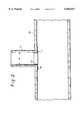
- FIG. 1is a cross-sectional view illustrating a cutting protection member.
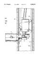
- FIGS. 2 through 6are cross-sectional views illustrating in order various steps of a pipe lining method according to the present invention.
- FIG. 7is a front view of a cutter used in the pipe lining method according to the present invention, with a left-hand portion showing a cross-sectional view of the cutter.
- FIG. 1is a cross-sectional view illustrating a cutting protection member 1 for use in a pipe lining method according to an embodiment of the present invention.
- the cutting protection member 1is made of a metal such as stainless steel (SUS) or the like, and is composed of a flange portion 1a and a cylindrical protector portion 1b integrally formed with the inner periphery of the flange portion 1a.
- SUSstainless steel
- the flange portion 1a of the cutting protection member 1has an outer diameter d1 larger than an inner diameter d of a branch pipe 11 (see FIG. 2), later described (d1>d), and is molded into an arcuate shape conformal to the inner wall of a main pipe 10 (see FIG. 2), later described.
- the protector portion 1b formed integrally with the inner periphery of the flange 1ahas an outer diameter d2 set slightly smaller than the inner diameter d of the branch pipe 11, and a height set in a range of 10 m/m to 50 m/m.
- FIGS. 2 through 6are cross-sectional views illustrating in order various steps of the pipe lining method according to an embodiment of the present invention.
- the cutting protection member 1 previously illustrated in FIG. 1is first fitted into a branch pipe opening (a portion of a branch pipe open to a main pipe) from a main pipe 10 and fixed with an arbitrary means (for example, an appropriate adhesive). Specifically, the cutting protection member 1 is attached along the periphery of the branch pipe opening of the main pipe 10 such that the flange portion 1a is closely contacted to the inner wall of the main pipe 10, and the protector portion 1b is fitted into the branch pipe 11.
- an arbitrary meansfor example, an appropriate adhesive
- the main pipeis lined using a main pipe liner bag 2, as illustrated in FIG. 3.
- the main pipe liner bag 2is everted and inserted into the main pipe 10 with a fluid pressure such as an air pressure or the like.
- the main pipe liner bag 2comprises a tubular resin-absorbent material having its outer peripheral surface covered with a highly air-tight plastic film 3, and an unhardened liquid thermosetting resin impregnated in the tubular resin-absorbent material.
- the tubular resin-absorbent materialis made of unwoven fabric such as polyester, polypropylene, acrylic fabric, or the like, and the unhardened liquid hardenable resin impregnated in the tubular resin-absorbent material may be a thermosetting resin such as unsaturated polyester resin, epoxy resin, vinyl ester resin, or the like.
- the plastic film 3may be molded into a seamless tubular shape by an inflation method, and a material suitable for the plastic film 3 may be selected from polyurethane, polyethylene, nylon, ethylene vinyl alcohol, admer, ionomer, vinyl chloride, and so on.
- the plastic film 3is applied over the entire outer surface of the tubular resin-absorbent material by thermal welding, bonding or coating.
- a cutting robot 12is introduced into the main pipe 10 for a cutting operation for cutting away the covering portion of the main pipe liner bag 2.
- the cutting robot 12is hydraulically driven to advance and retract its head 12a in the directions indicated by arrows a, and to rotate the head 12a in the directions indicated by arrows b.
- Pull ropes 13, 14are connected to the robot 12, and a TV camera 15 is installed on the top of the robot 12.
- the head 12a of the cutting robot 12is provided with a hydraulic cylinder 16, and a hydraulic motor 17 is supported by a rod 16a of the hydraulic cylinder 16 vertically movable in the directions indicated by arrows c in FIG. 5.
- a cutter 18 having an outer diameter smaller than the inner diameter of the cutting protection member 1is attached to an output shaft 17a of the hydraulic motor 17.
- the cutter 18includes a wire brush 18a sandwiched between upper and lower discoidal sanding disks 18b, and a rimer 18c on the top.
- the pull rope 13 or 14is pulled to move the cutting robot along the main pipe 10 in an appropriate direction in order to place the cutter 18 at a predetermined position. Subsequently, as the hydraulic motor 17 and the cutter 18 are moved upward while the hydraulic motor 17 is being driven to rotate the cutter 18, a portion of the main pipe liner bag 2 covering the branch pipe opening (a portion surrounded by the cutting protection member 1) is cut by the cutter 18.
- the cutting protection member 1functions as a guide for the cutter 18 as well as functions as a protection member for protecting the inner wall of the branch pipe 11, the main pipe liner bag 2 can be precisely cut away along the branch pipe opening using the cutter 18, thereby making it possible to prevent damages to the inner wall periphery of the branch pipe 11 and the cutter 18 itself.
- the wire brush 18a of the cutter 18can cut the main pipe liner bag 2 made of a hardened resin but cannot cut the cutting protection member 1 made of a metal, the cutting protection member 1 will never be cut by the cutter 18, whereby the inner wall of the branch pipe 11 and the cutter are more reliably protected by the cutting protection member 1 from damages.
- the branch pipe 11is open to the main pipe 10 so that they are in communication with each other, as illustrated in FIG. 6.
- the protection memberis attached along the periphery of a branch pipe opening of a main pipe before the main pipe is lined using a main pipe liner bag, and subsequently the main pipe is lined using the main pipe liner bag, so that the protection member functions as a guide for the remover such as cutter when removing a portion of the main pipe liner bag covering the branch pipe opening as well as functions as a protection member for protecting the inner wall periphery of the branch pipe, thereby making it possible to precisely remove the main pipe liner bag along the branch pipe opening and to prevent the inner wall periphery of the branch pipe opening from damages.
Landscapes
- Engineering & Computer Science (AREA)
- Manufacturing & Machinery (AREA)
- General Engineering & Computer Science (AREA)
- Mechanical Engineering (AREA)
- Lining Or Joining Of Plastics Or The Like (AREA)
- Pipe Accessories (AREA)
- Protection Of Pipes Against Damage, Friction, And Corrosion (AREA)
Abstract
Description
Claims (12)
Applications Claiming Priority (2)
| Application Number | Priority Date | Filing Date | Title |
|---|---|---|---|
| JP10014038AJPH11207821A (en) | 1998-01-27 | 1998-01-27 | Pipe lining method |
| JP10-014038 | 1998-01-27 |
Publications (1)
| Publication Number | Publication Date |
|---|---|
| US6056017Atrue US6056017A (en) | 2000-05-02 |
Family
ID=11849969
Family Applications (1)
| Application Number | Title | Priority Date | Filing Date |
|---|---|---|---|
| US09/238,275Expired - LifetimeUS6056017A (en) | 1998-01-27 | 1999-01-27 | Pipe lining method |
Country Status (7)
| Country | Link |
|---|---|
| US (1) | US6056017A (en) |
| EP (1) | EP0931639A3 (en) |
| JP (1) | JPH11207821A (en) |
| KR (1) | KR19990068142A (en) |
| AU (1) | AU1427799A (en) |
| CA (1) | CA2260464A1 (en) |
| TW (1) | TW434137B (en) |
Cited By (28)
| Publication number | Priority date | Publication date | Assignee | Title |
|---|---|---|---|---|
| US6154953A (en)* | 1997-08-08 | 2000-12-05 | Coflexip | Multi-tool system that can be used for connecting pipes |
| US6540439B2 (en)* | 2000-06-27 | 2003-04-01 | Terre Hill Silo Company | Junction seal between a liner of an underground structure and a penetrating pipe |
| US20030138298A1 (en)* | 2000-11-14 | 2003-07-24 | Sanexen Environmental Services Inc. | Method for rehabilitating conduits |
| US20040020544A1 (en)* | 2002-04-05 | 2004-02-05 | Takao Kamiyama | Pressure bag and method of lining branch pipe |
| US6887014B2 (en) | 2001-01-31 | 2005-05-03 | Cal Holland | Robotic apparatus and method for treatment of conduits |
| US20050241713A1 (en)* | 2004-04-28 | 2005-11-03 | Shonan Gosei-Jushi Seisakusho K.K. | Method for rehabilitating an existing pipe |
| US20060278290A1 (en)* | 2005-06-14 | 2006-12-14 | Warren Environmental, Inc. | Method of lining a pipeline |
| US20060290779A1 (en)* | 2005-01-18 | 2006-12-28 | Reverte Carlos F | Autonomous inspector mobile platform |
| US20070284876A1 (en)* | 2006-04-27 | 2007-12-13 | Polivka Richard C | Reinstatement of an existing connection in a lined conduit |
| US20080068601A1 (en)* | 2006-09-15 | 2008-03-20 | Thayer Scott M | Manhole modeler |
| US20090223336A1 (en)* | 2008-03-07 | 2009-09-10 | Shonan Gosei-Jushi Seisakusho K.K. | Apparatus for cutting lateral wall of pipe |
| US20090289451A1 (en)* | 2008-05-21 | 2009-11-26 | Ina Acquisition Corp. | T-Nut Assembly For Sealing An Existing Connection In A Lined Conduit |
| US20100018631A1 (en)* | 2005-11-23 | 2010-01-28 | Lmk Enterprises, Inc. | Method of repairing a manhole chimney using a stretchable sleeve |
| US20100191376A1 (en)* | 2004-10-01 | 2010-07-29 | Redzone Robotics, Inc. | Network architecture for remote robot with interchangeable tools |
| US20100218624A1 (en)* | 2008-11-03 | 2010-09-02 | Atwood Christopher C | Device for pipe inspection and method of using same |
| US20110030830A1 (en)* | 2009-08-07 | 2011-02-10 | Fer-Pal Construction Ltd. | Methods for rehabilitating conduits using structural liners |
| US20110232793A1 (en)* | 2010-03-24 | 2011-09-29 | Ina Acquisition Corp. | Wedge type plug and method of plugging a lateral line |
| US8170715B1 (en)* | 2005-01-25 | 2012-05-01 | Redzone Robotics, Inc. | Methods and devices for automated work in pipes based on impedance control |
| CN106931274A (en)* | 2017-04-23 | 2017-07-07 | 诸暨市合纵科技有限公司 | A pipeline robot that is easy to install a camera |
| US20190056054A1 (en)* | 2017-08-18 | 2019-02-21 | Sanexen Environmental Services Inc. | Method and Apparatus for Rehabilitation of Water Conduit with Lateral Openings |
| US10408373B2 (en) | 2014-04-17 | 2019-09-10 | Warren Environmental & Coating, Llc | Large diameter pipe lining and repair |
| US11079055B2 (en) | 2018-10-30 | 2021-08-03 | Ina Acquisition Corp. | Fitting for connecting a main pipe liner to a branch conduit |
| US20210310597A1 (en)* | 2018-05-07 | 2021-10-07 | Shonan Gosei-Jushi Seisakusho K.K. | Pipe robot |
| CN114046394A (en)* | 2021-11-19 | 2022-02-15 | 长春工业大学 | A kind of repair method for trenchless underground old water injection pipeline |
| CN114709747A (en)* | 2022-04-13 | 2022-07-05 | 华北电力大学(保定) | Self-adaptive special-shaped space cable pipeline inspection robot |
| US11391407B2 (en) | 2018-11-30 | 2022-07-19 | Ina Acquisition Corp. | Methods, systems, and apparatus for use in main pipes connected to branch conduit |
| US20220252200A1 (en)* | 2021-02-11 | 2022-08-11 | Ina Acquisition Corp. | Mobile system for pipe rehabilitation |
| US11774025B2 (en) | 2018-10-30 | 2023-10-03 | Ina Acquisition Corp. | Fitting for connecting a main pipe liner to a branch conduit |
Families Citing this family (8)
| Publication number | Priority date | Publication date | Assignee | Title |
|---|---|---|---|---|
| GB9906308D0 (en)* | 1999-03-18 | 1999-05-12 | Thames Water Utilities | Mains |
| JP4615756B2 (en)* | 2001-04-05 | 2011-01-19 | 積水化学工業株式会社 | Rehabilitation pipe inspection method |
| GB2475482B (en)* | 2009-11-18 | 2014-09-10 | Waterflow Group Plc | Method and apparatus for creating apertures in a pipeline |
| CN104608162B (en)* | 2014-12-30 | 2016-08-17 | 东莞理工学院 | Numerical control coil stock vibration sword cutting equipment |
| CN107405781A (en)* | 2015-04-07 | 2017-11-28 | 株式会社湘南合成树脂制作所 | Punching machine and method for punching |
| CN112077928B (en)* | 2020-08-19 | 2022-12-16 | 建湖双湖机械有限公司 | PE corrugated pipe punching device and working method thereof |
| DE102021118206B3 (en)* | 2021-07-14 | 2022-05-12 | Amex Sanivar Ag | Pipeline rehabilitation system and method for rehabilitation of a pipeline |
| CN115875533B (en)* | 2023-03-03 | 2023-05-09 | 济南和立新材料有限公司 | Lining pipe and repairing method thereof |
Citations (7)
| Publication number | Priority date | Publication date | Assignee | Title |
|---|---|---|---|---|
| US5329063A (en)* | 1991-05-31 | 1994-07-12 | Get, Inc. | Liner assembly for lining branch pipes and a method for manufacturing the liner assembly |
| US5439033A (en)* | 1993-09-28 | 1995-08-08 | Shonan Gosei-Jushi Seisakusho K.K. | Method of lining a branch pipe |
| US5454401A (en)* | 1993-08-31 | 1995-10-03 | Shonan Gosei-Jushi Seisakusho K.K. | Method of lining a branch pipe |
| US5566719A (en)* | 1994-07-05 | 1996-10-22 | Shonan Gosei-Jushi Seisakusho K.K. | Method for lining a branch pipe of an underground pipe |
| US5598873A (en)* | 1993-03-23 | 1997-02-04 | Shonan Gosei-Jushi Seisakusho K.K. | Branch pipe lining method and liner |
| US5692543A (en)* | 1992-12-07 | 1997-12-02 | Insituform (Netherlands) B.V. | Lining of lateral pipelines with a liner having a sealing collar |
| US5778937A (en)* | 1994-03-01 | 1998-07-14 | Klug Kanal-, Leitungs-Und Umweltsanierungs- G.M.B.H. | Method of making leakproof sites of entry of domestic connector pipes and similar feed pipes into sewers |
Family Cites Families (8)
| Publication number | Priority date | Publication date | Assignee | Title |
|---|---|---|---|---|
| US3762028A (en)* | 1972-02-25 | 1973-10-02 | Dow Chemical Co | Joining of plastic/metal foil laminates |
| FR2456280A1 (en)* | 1979-05-11 | 1980-12-05 | Syndicat Nal Prof Entre Trav D | CONNECTION FOR CONNECTING A DRAIN TO A MANIFOLD |
| US4893841A (en)* | 1989-04-20 | 1990-01-16 | Bowen William D | Reamer guide for primary sewer line taps |
| JPH08426B2 (en)* | 1993-04-13 | 1996-01-10 | 株式会社湘南合成樹脂製作所 | Pipe lining material and its manufacturing method and pipe repair method |
| JP2528430B2 (en)* | 1993-08-31 | 1996-08-28 | 株式会社湘南合成樹脂製作所 | Manufacturing method of branch pipe lining material |
| JPH0834055A (en)* | 1994-07-25 | 1996-02-06 | Shonan Gosei Jushi Seisakusho:Kk | Cutting and drilling apparatus |
| JP2974132B2 (en)* | 1997-02-04 | 1999-11-08 | 株式会社湘南合成樹脂製作所 | Pipe lining method |
| TW386936B (en)* | 1997-07-18 | 2000-04-11 | Get Inc | Making jig for a branch opening and pipe lining working method for a branch opening |
- 1998
- 1998-01-27JPJP10014038Apatent/JPH11207821A/enactivePending
- 1999
- 1999-01-26TWTW088101123Apatent/TW434137B/ennot_activeIP Right Cessation
- 1999-01-26CACA002260464Apatent/CA2260464A1/ennot_activeAbandoned
- 1999-01-26KRKR1019990002415Apatent/KR19990068142A/ennot_activeCeased
- 1999-01-27EPEP99300608Apatent/EP0931639A3/ennot_activeWithdrawn
- 1999-01-27USUS09/238,275patent/US6056017A/ennot_activeExpired - Lifetime
- 1999-01-29AUAU14277/99Apatent/AU1427799A/ennot_activeAbandoned
Patent Citations (7)
| Publication number | Priority date | Publication date | Assignee | Title |
|---|---|---|---|---|
| US5329063A (en)* | 1991-05-31 | 1994-07-12 | Get, Inc. | Liner assembly for lining branch pipes and a method for manufacturing the liner assembly |
| US5692543A (en)* | 1992-12-07 | 1997-12-02 | Insituform (Netherlands) B.V. | Lining of lateral pipelines with a liner having a sealing collar |
| US5598873A (en)* | 1993-03-23 | 1997-02-04 | Shonan Gosei-Jushi Seisakusho K.K. | Branch pipe lining method and liner |
| US5454401A (en)* | 1993-08-31 | 1995-10-03 | Shonan Gosei-Jushi Seisakusho K.K. | Method of lining a branch pipe |
| US5439033A (en)* | 1993-09-28 | 1995-08-08 | Shonan Gosei-Jushi Seisakusho K.K. | Method of lining a branch pipe |
| US5778937A (en)* | 1994-03-01 | 1998-07-14 | Klug Kanal-, Leitungs-Und Umweltsanierungs- G.M.B.H. | Method of making leakproof sites of entry of domestic connector pipes and similar feed pipes into sewers |
| US5566719A (en)* | 1994-07-05 | 1996-10-22 | Shonan Gosei-Jushi Seisakusho K.K. | Method for lining a branch pipe of an underground pipe |
Non-Patent Citations (1)
| Title |
|---|
| UK Patent Application 2041147 Bridgestock, Sep. 1980.* |
Cited By (46)
| Publication number | Priority date | Publication date | Assignee | Title |
|---|---|---|---|---|
| US6154953A (en)* | 1997-08-08 | 2000-12-05 | Coflexip | Multi-tool system that can be used for connecting pipes |
| US7121766B2 (en) | 2000-06-27 | 2006-10-17 | Terre Hill Silo Company | Inflatable underground structure liner |
| US6540439B2 (en)* | 2000-06-27 | 2003-04-01 | Terre Hill Silo Company | Junction seal between a liner of an underground structure and a penetrating pipe |
| US20030138298A1 (en)* | 2000-11-14 | 2003-07-24 | Sanexen Environmental Services Inc. | Method for rehabilitating conduits |
| US6887014B2 (en) | 2001-01-31 | 2005-05-03 | Cal Holland | Robotic apparatus and method for treatment of conduits |
| US20040020544A1 (en)* | 2002-04-05 | 2004-02-05 | Takao Kamiyama | Pressure bag and method of lining branch pipe |
| US20050241713A1 (en)* | 2004-04-28 | 2005-11-03 | Shonan Gosei-Jushi Seisakusho K.K. | Method for rehabilitating an existing pipe |
| US7028716B2 (en)* | 2004-05-28 | 2006-04-18 | Shonan Gosei-Jushi Seisakusho K.K. | Method for rehabilitating an existing pipe |
| US20100191376A1 (en)* | 2004-10-01 | 2010-07-29 | Redzone Robotics, Inc. | Network architecture for remote robot with interchangeable tools |
| US8060257B2 (en) | 2004-10-01 | 2011-11-15 | Redzone Robotics, Inc. | Network architecture for remote robot with interchangeable tools |
| US8024066B2 (en) | 2005-01-18 | 2011-09-20 | Redzone Robotics, Inc. | Autonomous inspector mobile platform |
| US20060290779A1 (en)* | 2005-01-18 | 2006-12-28 | Reverte Carlos F | Autonomous inspector mobile platform |
| US8170715B1 (en)* | 2005-01-25 | 2012-05-01 | Redzone Robotics, Inc. | Methods and devices for automated work in pipes based on impedance control |
| US20060278290A1 (en)* | 2005-06-14 | 2006-12-14 | Warren Environmental, Inc. | Method of lining a pipeline |
| US7270150B2 (en)* | 2005-06-14 | 2007-09-18 | Warren Environmental, Inc. | Method of lining a pipeline |
| US8721216B2 (en) | 2005-11-23 | 2014-05-13 | Lmk Enterprises, Inc. | Method of repairing a manhole chimney using a stretchable sleeve |
| US20100018631A1 (en)* | 2005-11-23 | 2010-01-28 | Lmk Enterprises, Inc. | Method of repairing a manhole chimney using a stretchable sleeve |
| US20070284876A1 (en)* | 2006-04-27 | 2007-12-13 | Polivka Richard C | Reinstatement of an existing connection in a lined conduit |
| US8015695B2 (en) | 2006-04-27 | 2011-09-13 | Ina Acquisition Corp. | Reinstatement of an existing connection in a lined conduit |
| US20080068601A1 (en)* | 2006-09-15 | 2008-03-20 | Thayer Scott M | Manhole modeler |
| US8467049B2 (en) | 2006-09-15 | 2013-06-18 | RedzoneRobotics, Inc. | Manhole modeler using a plurality of scanners to monitor the conduit walls and exterior |
| US8202142B2 (en)* | 2008-03-07 | 2012-06-19 | Shonan Gosei-Jushi Seisakusho K.K. | Apparatus for cutting lateral wall of pipe |
| US20090223336A1 (en)* | 2008-03-07 | 2009-09-10 | Shonan Gosei-Jushi Seisakusho K.K. | Apparatus for cutting lateral wall of pipe |
| US20090289451A1 (en)* | 2008-05-21 | 2009-11-26 | Ina Acquisition Corp. | T-Nut Assembly For Sealing An Existing Connection In A Lined Conduit |
| US8525124B2 (en) | 2008-11-03 | 2013-09-03 | Redzone Robotics, Inc. | Device for pipe inspection and method of using same |
| US20100218624A1 (en)* | 2008-11-03 | 2010-09-02 | Atwood Christopher C | Device for pipe inspection and method of using same |
| US8272406B2 (en)* | 2009-08-07 | 2012-09-25 | Fer-Pal Construction Ltd. | Methods for rehabilitating conduits using structural liners |
| US20110030830A1 (en)* | 2009-08-07 | 2011-02-10 | Fer-Pal Construction Ltd. | Methods for rehabilitating conduits using structural liners |
| US20110232793A1 (en)* | 2010-03-24 | 2011-09-29 | Ina Acquisition Corp. | Wedge type plug and method of plugging a lateral line |
| US8820363B2 (en) | 2010-03-24 | 2014-09-02 | Ina Acquisition Corp. | Wedge type plug and method of plugging a lateral line |
| US10408373B2 (en) | 2014-04-17 | 2019-09-10 | Warren Environmental & Coating, Llc | Large diameter pipe lining and repair |
| CN106931274A (en)* | 2017-04-23 | 2017-07-07 | 诸暨市合纵科技有限公司 | A pipeline robot that is easy to install a camera |
| CN106931274B (en)* | 2017-04-23 | 2018-08-21 | 诸暨市合纵科技有限公司 | A pipeline robot that is easy to install a camera |
| US20190056054A1 (en)* | 2017-08-18 | 2019-02-21 | Sanexen Environmental Services Inc. | Method and Apparatus for Rehabilitation of Water Conduit with Lateral Openings |
| US10386006B2 (en)* | 2017-08-18 | 2019-08-20 | Sanexen Environmental Services Inc. | Method and apparatus for rehabilitation of water conduit with lateral openings |
| US20210310597A1 (en)* | 2018-05-07 | 2021-10-07 | Shonan Gosei-Jushi Seisakusho K.K. | Pipe robot |
| US11821566B2 (en)* | 2018-05-07 | 2023-11-21 | Shonan Gosei-Jushi Seisakusho K.K. | Pipe robot |
| US11079055B2 (en) | 2018-10-30 | 2021-08-03 | Ina Acquisition Corp. | Fitting for connecting a main pipe liner to a branch conduit |
| US11774025B2 (en) | 2018-10-30 | 2023-10-03 | Ina Acquisition Corp. | Fitting for connecting a main pipe liner to a branch conduit |
| US11391407B2 (en) | 2018-11-30 | 2022-07-19 | Ina Acquisition Corp. | Methods, systems, and apparatus for use in main pipes connected to branch conduit |
| US11828400B2 (en) | 2018-11-30 | 2023-11-28 | Ina Acquisition Corp. | Methods, systems, and apparatus for use in main pipes connected to branch conduit |
| US20220252200A1 (en)* | 2021-02-11 | 2022-08-11 | Ina Acquisition Corp. | Mobile system for pipe rehabilitation |
| US12123537B2 (en)* | 2021-02-11 | 2024-10-22 | Ina Acquisition Corp. | Mobile system for pipe rehabilitation |
| CN114046394A (en)* | 2021-11-19 | 2022-02-15 | 长春工业大学 | A kind of repair method for trenchless underground old water injection pipeline |
| CN114709747A (en)* | 2022-04-13 | 2022-07-05 | 华北电力大学(保定) | Self-adaptive special-shaped space cable pipeline inspection robot |
| CN114709747B (en)* | 2022-04-13 | 2023-05-12 | 华北电力大学(保定) | Self-adaptive special-shaped space cable duct inspection robot |
Also Published As
| Publication number | Publication date |
|---|---|
| JPH11207821A (en) | 1999-08-03 |
| EP0931639A2 (en) | 1999-07-28 |
| EP0931639A3 (en) | 2000-01-26 |
| KR19990068142A (en) | 1999-08-25 |
| AU1427799A (en) | 1999-08-19 |
| CA2260464A1 (en) | 1999-07-27 |
| TW434137B (en) | 2001-05-16 |
Similar Documents
| Publication | Publication Date | Title |
|---|---|---|
| US6056017A (en) | Pipe lining method | |
| EP0620102B1 (en) | Branch pipe lining method and liner | |
| US6158473A (en) | Branch pipe liner bag and pipe lining method | |
| US5944058A (en) | Branch pipe liner assembly and a pipe lining method | |
| EP0938964B1 (en) | Branch pipe liner bag and branch pipe lining method | |
| EP1653145B1 (en) | Lateral pipe lining material and lateral pipe lining method | |
| US6085794A (en) | Pipe lining method | |
| US6206993B1 (en) | Method and apparatus for providing a tubular material within a pipeline | |
| EP0691507B1 (en) | A method for lining a branch pipe of an underground pipe | |
| US6123109A (en) | Branch pipe lining bag and pipe lining method | |
| US6006787A (en) | Branch pipe liner bag and branch pipe lining method | |
| EP0856697B1 (en) | Pipe lining method | |
| EP0620101B1 (en) | Method and apparatus for lining a branch pipe | |
| EP0891857B1 (en) | Device for confirming the position of branch pipe opening and pipe lining method using the device | |
| EP0911568B1 (en) | A branch pipe lining assembly and a pipe lining method | |
| JP2678148B2 (en) | Branch pipe lining material and branch pipe lining method | |
| JP2702099B2 (en) | Start liner with flange for branch pipe and pipe lining method | |
| AU7841098A (en) | Device for confirming the position of branch pipe opening and pipe lining method using the device |
Legal Events
| Date | Code | Title | Description |
|---|---|---|---|
| AS | Assignment | Owner name:SHONAN GOSEI-JUSHI SEISAKUSHO K.K., JAPAN Free format text:ASSIGNMENT OF ASSIGNORS INTEREST;ASSIGNORS:KAMIYAMA, TAKAO;YOKOSHIMA, YASUHIRO;ENDOH, SHIGERU;AND OTHERS;REEL/FRAME:009736/0539;SIGNING DATES FROM 19990109 TO 19990116 Owner name:GET INC., JAPAN Free format text:ASSIGNMENT OF ASSIGNORS INTEREST;ASSIGNORS:KAMIYAMA, TAKAO;YOKOSHIMA, YASUHIRO;ENDOH, SHIGERU;AND OTHERS;REEL/FRAME:009736/0539;SIGNING DATES FROM 19990109 TO 19990116 Owner name:OAR COMPANY, JAPAN Free format text:ASSIGNMENT OF ASSIGNORS INTEREST;ASSIGNORS:KAMIYAMA, TAKAO;YOKOSHIMA, YASUHIRO;ENDOH, SHIGERU;AND OTHERS;REEL/FRAME:009736/0539;SIGNING DATES FROM 19990109 TO 19990116 Owner name:YOKOSHIMA & COMPANY, JAPAN Free format text:ASSIGNMENT OF ASSIGNORS INTEREST;ASSIGNORS:KAMIYAMA, TAKAO;YOKOSHIMA, YASUHIRO;ENDOH, SHIGERU;AND OTHERS;REEL/FRAME:009736/0539;SIGNING DATES FROM 19990109 TO 19990116 | |
| STCF | Information on status: patent grant | Free format text:PATENTED CASE | |
| FPAY | Fee payment | Year of fee payment:4 | |
| FEPP | Fee payment procedure | Free format text:PAYER NUMBER DE-ASSIGNED (ORIGINAL EVENT CODE: RMPN); ENTITY STATUS OF PATENT OWNER: SMALL ENTITY Free format text:PAYOR NUMBER ASSIGNED (ORIGINAL EVENT CODE: ASPN); ENTITY STATUS OF PATENT OWNER: SMALL ENTITY | |
| FPAY | Fee payment | Year of fee payment:8 | |
| FPAY | Fee payment | Year of fee payment:12 |