US6055946A - Crankshaft-mounted cooling fan with power takeoff capability - Google Patents
Crankshaft-mounted cooling fan with power takeoff capabilityDownload PDFInfo
- Publication number
- US6055946A US6055946AUS09/365,966US36596699AUS6055946AUS 6055946 AUS6055946 AUS 6055946AUS 36596699 AUS36596699 AUS 36596699AUS 6055946 AUS6055946 AUS 6055946A
- Authority
- US
- United States
- Prior art keywords
- adapter
- fan
- assembly
- planet
- gear
- Prior art date
- Legal status (The legal status is an assumption and is not a legal conclusion. Google has not performed a legal analysis and makes no representation as to the accuracy of the status listed.)
- Expired - Fee Related
Links
Images

Classifications
- F—MECHANICAL ENGINEERING; LIGHTING; HEATING; WEAPONS; BLASTING
- F01—MACHINES OR ENGINES IN GENERAL; ENGINE PLANTS IN GENERAL; STEAM ENGINES
- F01P—COOLING OF MACHINES OR ENGINES IN GENERAL; COOLING OF INTERNAL-COMBUSTION ENGINES
- F01P5/00—Pumping cooling-air or liquid coolants
- F01P5/02—Pumping cooling-air; Arrangements of cooling-air pumps, e.g. fans or blowers
- F01P5/04—Pump-driving arrangements
- F—MECHANICAL ENGINEERING; LIGHTING; HEATING; WEAPONS; BLASTING
- F01—MACHINES OR ENGINES IN GENERAL; ENGINE PLANTS IN GENERAL; STEAM ENGINES
- F01P—COOLING OF MACHINES OR ENGINES IN GENERAL; COOLING OF INTERNAL-COMBUSTION ENGINES
- F01P7/00—Controlling of coolant flow
- F01P7/02—Controlling of coolant flow the coolant being cooling-air
- F01P7/08—Controlling of coolant flow the coolant being cooling-air by cutting in or out of pumps
- F01P7/081—Controlling of coolant flow the coolant being cooling-air by cutting in or out of pumps using clutches, e.g. electro-magnetic or induction clutches
- F01P7/082—Controlling of coolant flow the coolant being cooling-air by cutting in or out of pumps using clutches, e.g. electro-magnetic or induction clutches using friction clutches
- F01P7/084—Controlling of coolant flow the coolant being cooling-air by cutting in or out of pumps using clutches, e.g. electro-magnetic or induction clutches using friction clutches actuated electromagnetically
- F—MECHANICAL ENGINEERING; LIGHTING; HEATING; WEAPONS; BLASTING
- F01—MACHINES OR ENGINES IN GENERAL; ENGINE PLANTS IN GENERAL; STEAM ENGINES
- F01P—COOLING OF MACHINES OR ENGINES IN GENERAL; COOLING OF INTERNAL-COMBUSTION ENGINES
- F01P2025/00—Measuring
- F01P2025/60—Operating parameters
- F01P2025/66—Vehicle speed
Definitions
- the present inventionrelates generally to cooling fans for engines. More particularly, the present invention relates to cooling fans mounted on the crankshaft of an internal combustion engine.
- a lower hood lineimproves a truck's aerodynamics, thus reducing fuel consumption.
- a lower hood linealso improves the line of site of the driver, thus providing for safer operation of the truck or motor vehicle.
- the cooling fanis mounted above the crankshaft in many configurations.
- the crankshaftpowers the fan to cool the engine through pulleys and a fan belt.
- a crankshaft-mounted cooling fanenables the hood line of a truck or motor vehicle to be lowered. It eliminates the need for pulleys and a fan belt to drive the fan. Consequently, there is more space in the engine cavity for auxiliary equipment. Alternatively, the engine cavity may be reduced. In addition, an engine is more reliable without a fan belt.
- crankshaft-mounted cooling fanshave adverse effects on engine performance and operation. These fans run only at the speed of the crankshaft, i.e. the engine speed. Consequently, the fan does not run fast enough when the engine needs the most cooling during idle, slow speeds, and other times.
- these fanscannot be disengaged from the crankshaft when the engine does not need the fan.
- an enginedoes not need the fan to operate during engine warm-up.
- An operating fanwould extend the warm-up period and take energy from the engine.
- an enginedoes not need the fan to operate when the truck or motor vehicle is moving at higher speeds. The airflow at higher speeds is sufficient to cool the engine.
- an operating fanbecomes a drag on the engine, reducing engine performance and lowering fuel efficiency.
- a typical crankshaft-mounted fanprohibits power takeoff from the front of the engine. With the fan blocking the crankshaft, it is impossible to connect a power takeoff device to the crankshaft. Consequently, these fans limit the use of power takeoff devices to the rear of the truck or vehicle.
- crankshaft-mounted cooling fanthat operates faster than the engine speed, can be turned on/off when needed, and has power takeoff capability through the crankshaft.
- the present inventionprovides a clutched, speed-rated, crankshaft-mounted cooling fan with full drive through capability.
- the cooling fanhas an adapter mounted on the engine's crankshaft.
- the adapterextends beyond the engine's front cover and is capable of being coupled to a power takeoff device (PTO).
- PTOpower takeoff device
- a PTOis not required to operate the fan, thus permitting the PTO to be added at a later date.
- the PTOmay be coupled to the adapter inside or outside of the engine cavity.
- the adapteris operatively connected to first and second adapter bearings, which in turn are operatively connected to a planetary gear assembly.
- the planetary gear assemblyhas a drive gear, one or more planet assemblies, and a fan gear.
- the drive gearhas a gear portion and plate extension.
- the gear portion of the drive gearengages one or more planet assemblies.
- the fan gearhas a gear section and a fan extension for coupling with a fan blade set.
- Each planet assemblyhas a planet bolt for coupling a power transfer gear coupled to a fan drive gear.
- the power transfer gearengages the drive gear at its gear portion.
- the fan drive gearengages the fan gear at its gear section.
- the planet assemblyis operatively connected to a fan housing.
- the planet boltis positioned within a planet bearing, which is located inside a cavity formed by a planet support on the housing.
- a fan bearingis operatively connected to the housing and the fan extension.
- the fan housingconnects to the engine.
- a clutch assemblyis attached to the adapter in a position where a clutch plate may engage the plate extension of the drive gear.
- a solenoidis connected to the fan housing and is disposed for activating the clutch assembly.
- the adapterIn operation, the adapter is rotating at the engine speed.
- the clutch plateengages the plate extension on the drive gear.
- the drive gearrotates the power transfer gear, which in turn rotates the fan drive gear.
- the fan drive gearrotates the fan gear, which in turn rotates the fan blade set.
- the gear ratios of the planetary gear assemblyare chosen so the fan blade set rotates at a faster speed than the engine. Fan ratios of 1.2 or 1.3 are suitable for most internal combustion engines.
- the clutch assemblymay be activated or deactivated depending on the operating parameters of the engine or a motor vehicle. For example, the clutch may be activated when the engine temperature rises above a particular temperature. The clutch may be deactivated when the vehicle goes faster than a certain speed.
- a microprocessormay be used to control the clutch assembly.
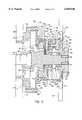
- FIG. 1is a cross-sectional side view of a crankshaft-mounted fan with a power takeoff device according to the present invention
- FIG. 2is a cross-sectional side view of a crankshaft-mounted fan without a power takeoff device according to the present invention.
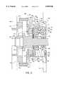
- FIG. 3is a cross-sectional front view of section A--A of the crankshaft-mounted fan in FIG. 1.
- FIG. 1shows the crankshaft-mounted fan 100 of the present invention.
- the crankshaft-mounted fan 100includes an adapter 104, a clutch assembly 136, and a planetary gear assembly 141 within a fan housing 110.
- the adapter 104is capable of connecting to a power takeoff device 164.
- the planetary gear assemblyconnects to a fan blade set 174.
- the adapter 104connects to a crankshaft 102 via a damper 106.
- the crankshaftis operatively positioned within an engine (not shown).
- the adapter 104extends beyond a front cover 108 of the engine to form an extension of the crankshaft 102.
- the adapter 104is made of cast or forged steel. However, it may be made from other materials or a combination suitable to withstand the torsional and other forces during operation of the fan.
- the adapter 104is operatively connected to a first adapter bearing 170 and a second adapter bearing 172. During operation of the engine, the adapter 104 rotates essentially at the same speed and in the same direction as the crankshaft 102. The adapter 104 also rotates freely against the first adapter bearing 170 and the second adapter bearing 172.
- the clutch assembly 136is attached to the adapter 104 and includes a flywheel 138 and a clutch plate 140.
- the clutch assembly 136is made of cast or forged steel. However, it may be made from other materials or a combination suitable to withstand the torsional, frictional, and other forces during operation of the fan. When the engine is running, the clutch assembly 136 rotates essentially at the same speed and in the same direction as the adapter 104.
- the power takeoff device (PTO) 164may be connected to the adapter 104 using bolts 166, 168. Other methods may be used to connect adapter 104 and PTO such as a lock pin (not shown) or a coupling (not shown). PTO 164 is not required for operation of the crankshaft-mounted fan 100.
- FIG. 2shows a crankshaft-mounted fan 200 of the present invention without a power takeoff device.
- PTO 164may be included when the engine is built or it may be added at a later date.
- PTO 164may be any power takeoff device capable of using or of being adapted to use the direct drive from the engine. If space is available, PTO 164 may be mounted in the engine cavity as shown in FIG. 1. If no space is available, PTO 164 may be mounted outside the engine cavity (not shown). In which case, the adapter 104 would extend to PTO 164 (for example, directly through the radiator). Conversely, the adapter 104 could connect indirectly to PTO 164 using gears, belts and pulleys, or similar means (not shown).
- the fan housing 110includes a base housing 112, a solenoid support housing 116, and a gear housing 118.
- the fan housing 110is made of cast iron or steel.
- the housingmay be made from other materials or a combination.
- the base housing 112is coupled to the front cover 108 of the engine.
- the base housing 112forms a base extension 114 for connecting to the solenoid support housing 116 using bolts 120, 126 and other bolts not shown.
- the gear housing 118connects to the solenoid support housing 116 using bolts 122, 124 and other bolts not shown. While bolts are preferred for connecting the housings, other connection methods may be used such as rivets and welding. Even though the housings are shown as separate pieces, the housings could be a single piece, different multiple pieces, or different configurations.
- the gear housing 118forms a first planet support 128, which has a cavity for holding the first planet bearing 130.
- the gear housing 118also forms a second planet support 228 and a third planet support 328 as seen in FIG. 3.
- the second and third planet supports 228, 328are the same as planet support 128. However, they could have different sizes and shapes.
- the second and third planet supports 228, 328have cavities for holding second and third planet bearings (not shown).
- the planetary gear assembly 141has a drive gear 142, a fan gear 156, and three planet assemblies.
- the planetary gear assembly 141is made of cast or forged steel. However, it may be made from other materials, or a combination.
- the planet assembliesare substantially identical to each other. One planet assembly is mounted in each of the planet supports 128, 228, 328 formed on the gear housing 118.
- the first planet assembly 148is described in detail.
- the second and the third planet assembliesare not described in detail because it is understood they have essentially the same structure, components, and interactions with other parts as the first planet assembly 148.
- a first planet assembly 148includes a first power transfer gear 150, a first fan drive gear 152, and a first planet bolt 154.
- the first planet bolt 154is positioned inside the first planet bearing 130 for connecting the first power transfer gear 150 and the first fan drive gear 152 on opposite sides of the first planet support 128. Once assembled on the first planet support 128, the first planet assembly 148 rotates freely inside the first planet bearing 130.
- the first power transfer gear 150engages the gear portion 144 of the drive gear 142, which has a plate extension 146.
- Drive gear 142is positioned operatively between the first power transfer gear 150 and the first adapter bearing 170 located on the adapter 104.
- the gear portion 144engages the first power transfer gear 150.
- the plate extension 146is positioned for contact with the clutch plate 140 when clutch assembly 136 is activated.
- a solenoid 132is mounted on the solenoid support housing 116.
- the solenoid 132is located adjacent to but not touching the clutch assembly 136 for engaging and disengaging the clutch plate 140.
- a control wire 134provides electrical power to the solenoid 132 for engaging and disengaging the clutch plate 140. While an electrical clutch is preferred, other clutches may be used such as a viscous or pneumatic type.
- a microprocessor(not shown) is used to control the operation of clutch assembly 136.
- Any type of microprocessormay be used that is suitable for use in a motor vehicle and is capable of performing the control features.
- a logic circuit or other electrical circuitrymay be used.
- the microprocessorengages and disengages the clutch plate 140 and the plate extension 146 based on operating parameters of the engine and the motor vehicle. For example, the microprocessor engages the clutch plate 140 when temperature sensors indicate the engine temperature has risen above a predetermined temperature. The temperature sensors may measure the temperature of the cooling fluid, the temperature of the oil, or other temperatures to ascertain the engine temperature. In another example, the microprocessor disengages the clutch plate 140 when sensors indicate the speed of the motor vehicle is faster than a predetermined speed.
- the first fan drive gear 152engages the fan gear 156, which has a gear section 158 and a fan extension 160.
- Fan gear 156is positioned operatively between the first fan drive gear 152 and the second adapter bearing 172 located on adapter 104.
- the gear section 158engages the first fan drive gear 152.
- Fan extension 160is operatively connected to fan bearing 162 located on gear housing 118.
- the fan bearingmay be a gasket or other suitable material to buffer the gearing housing 118 from operation of the fan gear 156.
- the fan extension 160is coupled to the fan blade set 174.
- the fan blade set 174may be any fan suitable for use in an engine.
- the fan blade set 174is made of plastic or other polymer.
- the fan blade set 174may be made from other materials or a combination.
- the fan blade set 174may include one or more arms and blades as illustrated in FIGS. 1 and 2. It may include a support ring (not shown) for snap fitting or otherwise connecting the fan blade set 174 to the fan extension 160. Such support ring may include or otherwise take the place of the fan bearing 162.
- FIG. 3shows a front, cross-sectional view of the crankshaft-mounted fan 100 according to the present invention.
- the gear housing 118forms the first planet support 128, the second planet support 228, and the third planet support 338.
- the first planet assembly 148is connected to the first planet support 128.
- the first planet bolt 154connects the first fan drive gear 152 to the first power transfer gear 150 (hidden).
- the first planet bolt 154is positioned inside the first planet bearing 130 (hidden) located in a cavity formed by planet support 128.
- the first power transfer gear 150 (hidden)engages the gear portion 144 (hidden) of the drive gear 142.
- the second planet assembly 248is connected to the second planet support 228.
- the second planet bolt 254connects the second fan drive gear 252 to the second power transfer gear (hidden).
- the second planet bolt 254is positioned inside the second planet bearing (hidden) located in a cavity formed by planet support 228.
- the second power transfer gear (hidden)engages the gear portion 144 (hidden) of the drive gear 142.
- the third planet assembly 348is connected to the third planet support 328.
- the third planet bolt 354connects the third fan drive gear 352 to the third power transfer gear (hidden).
- the third planet bolt 354is positioned inside the third planet bearing (hidden) located in a cavity formed by planet support 328.
- the first, second, and third power transfer gearsengage the gear portion 144 (hidden) of the drive gear 142.
- the plate extension 146 of the drive gear 142is positioned to engage the clutch plate 140 (hidden).
- the first, second, and third fan drive gears 152, 252, 352engage the gear section 158 of the fan gear 156.
- the gear section 158is operatively positioned between the first fan drive gear 152 and the second adapter bearing 172 for the fan gear 156 to rotate around the adapter 104.
- the planetary gear assembly 141includes three planet assemblies 152, 252, 353 having an equal distance--120° from each other--around the adapter.
- the planet assembliesmay be unequal distances from each other.
- Other planetary gear arrangementsmay also be used.
- clutch assembly 136is activated to rotate the fan blade set 174.
- the clutch plate 140engages plate extension 146 to rotate the planetary gear assembly 141, which in turn rotates the fan blade set 174.
- clutch assembly 136is deactivated to stop rotating the fan blade set 174.
- the clutch plate 140disengages from plate extension 146 to stop rotating the planetary gear assembly 141, which in turn stops rotating the fan blade set 174.
- the fan blade set 174may not stop turning completely. Inertia may keep the fan blade set 174 turning. While the truck or vehicle is moving, the airflow through the engine cavity may rotate fan blade set 174.
- Clutch assembly 136may be activated and deactivated at any time depending on the operation of the engine or motor vehicle.
- the clutch assembly 136may be activated once the engine is warmed-up and deactivated once the truck or vehicle exceeds a particular speed.
- the clutch assembly 136may be activated or deactivated depending on operating parameters of the engine. For example, temperature sensors (not shown) in the oil reservoir or radiator may activate or deactivate the clutch assembly 136 based on the temperature of the oil or cooling fluid. Other sensors may deactivate the clutch assembly 136 when the motor vehicle exceeds a particular speed.
- an electrical signal on the control wire 134energizes the solenoid 132.
- the energized solenoid 132forces the clutch plate 140 to engage the plate extension 146 of the drive gear 142.
- a pneumatic or viscous clutch assemblywould operate differently.
- the drive gear 142rotates essentially at the same speed as the adapter 104 (i.e. the engine speed).
- Drive gear 142rotates the power transfer gears on the planet assemblies, which rotate the fan drive gear via the planet bolts.
- the fan drive gearsrotate the fan gear 156, which rotates the fan blade set 174.
- the crankshaft-mounted fan 100has a fan ratio designed for the airflow needs of the particular engine on which the fan is used. In most applications, the fan must to run faster than the engine speed when clutch assembly 136 is engaged. Generally, fan ratios of 1.2 and 1.3 are sufficient for most internal combustion engines. These fan ratios mean the fan blade set 174 spins 20 or 30 percent faster, respectively, than the engine speed when the clutch plate 140 is engaged. Alternate gear sizes and arrangements may be chosen to obtain a desired fan ratio. Other fan ratios may be used to obtain different fan speeds even a fan speed slower than the engine speed (i.e. a fan ration less than 1).
- the drive gear 124has 56 teeth (not shown).
- Each of the power transfer gearshas 20 teeth (not shown).
- Each of the fan drive gearshas 25 teeth (not shown).
- the fan gear 140has 58 teeth (not shown).
- the gearsmay have different combinations of gear teeth and yet have a fan ration of 1.2.
Landscapes
- Engineering & Computer Science (AREA)
- Chemical & Material Sciences (AREA)
- Combustion & Propulsion (AREA)
- Mechanical Engineering (AREA)
- General Engineering & Computer Science (AREA)
- Physics & Mathematics (AREA)
- Electromagnetism (AREA)
- Auxiliary Drives, Propulsion Controls, And Safety Devices (AREA)
Abstract
Description
The present invention relates generally to cooling fans for engines. More particularly, the present invention relates to cooling fans mounted on the crankshaft of an internal combustion engine.
Better fuel economy and enhanced safety are benefits from lower hood lines on trucks and other motor vehicles. A lower hood line improves a truck's aerodynamics, thus reducing fuel consumption. A lower hood line also improves the line of site of the driver, thus providing for safer operation of the truck or motor vehicle.
One obstacle to lowering the hood line is the position of the cooling fan on the engine. The cooling fan is mounted above the crankshaft in many configurations. The crankshaft powers the fan to cool the engine through pulleys and a fan belt.
In contrast, a crankshaft-mounted cooling fan enables the hood line of a truck or motor vehicle to be lowered. It eliminates the need for pulleys and a fan belt to drive the fan. Consequently, there is more space in the engine cavity for auxiliary equipment. Alternatively, the engine cavity may be reduced. In addition, an engine is more reliable without a fan belt.
Even with these benefits, typical crankshaft-mounted cooling fans have adverse effects on engine performance and operation. These fans run only at the speed of the crankshaft, i.e. the engine speed. Consequently, the fan does not run fast enough when the engine needs the most cooling during idle, slow speeds, and other times.
Moreover, these fans cannot be disengaged from the crankshaft when the engine does not need the fan. For example, an engine does not need the fan to operate during engine warm-up. An operating fan would extend the warm-up period and take energy from the engine. Similarly, an engine does not need the fan to operate when the truck or motor vehicle is moving at higher speeds. The airflow at higher speeds is sufficient to cool the engine. In addition, an operating fan becomes a drag on the engine, reducing engine performance and lowering fuel efficiency.
Finally, a typical crankshaft-mounted fan prohibits power takeoff from the front of the engine. With the fan blocking the crankshaft, it is impossible to connect a power takeoff device to the crankshaft. Consequently, these fans limit the use of power takeoff devices to the rear of the truck or vehicle.
Accordingly, there is a need for a crankshaft-mounted cooling fan that operates faster than the engine speed, can be turned on/off when needed, and has power takeoff capability through the crankshaft.
The present invention provides a clutched, speed-rated, crankshaft-mounted cooling fan with full drive through capability. The cooling fan has an adapter mounted on the engine's crankshaft. The adapter extends beyond the engine's front cover and is capable of being coupled to a power takeoff device (PTO). A PTO is not required to operate the fan, thus permitting the PTO to be added at a later date. The PTO may be coupled to the adapter inside or outside of the engine cavity.
The adapter is operatively connected to first and second adapter bearings, which in turn are operatively connected to a planetary gear assembly. The planetary gear assembly has a drive gear, one or more planet assemblies, and a fan gear.
The drive gear has a gear portion and plate extension. The gear portion of the drive gear engages one or more planet assemblies. The fan gear has a gear section and a fan extension for coupling with a fan blade set.
Each planet assembly has a planet bolt for coupling a power transfer gear coupled to a fan drive gear. The power transfer gear engages the drive gear at its gear portion. The fan drive gear engages the fan gear at its gear section.
The planet assembly is operatively connected to a fan housing. The planet bolt is positioned within a planet bearing, which is located inside a cavity formed by a planet support on the housing. In addition, a fan bearing is operatively connected to the housing and the fan extension. The fan housing connects to the engine.
A clutch assembly is attached to the adapter in a position where a clutch plate may engage the plate extension of the drive gear. A solenoid is connected to the fan housing and is disposed for activating the clutch assembly.
In operation, the adapter is rotating at the engine speed. When the clutch assembly is activated, the clutch plate engages the plate extension on the drive gear. The drive gear rotates the power transfer gear, which in turn rotates the fan drive gear. The fan drive gear rotates the fan gear, which in turn rotates the fan blade set.
The gear ratios of the planetary gear assembly are chosen so the fan blade set rotates at a faster speed than the engine. Fan ratios of 1.2 or 1.3 are suitable for most internal combustion engines. The clutch assembly may be activated or deactivated depending on the operating parameters of the engine or a motor vehicle. For example, the clutch may be activated when the engine temperature rises above a particular temperature. The clutch may be deactivated when the vehicle goes faster than a certain speed. A microprocessor may be used to control the clutch assembly.
The following drawings and description set forth additional advantages and benefits of the invention. More advantages and benefits are obvious from the description and may be learned by practice of the invention.
The present invention may be better understood when read in connection with the accompanying drawings, of which:
FIG. 1 is a cross-sectional side view of a crankshaft-mounted fan with a power takeoff device according to the present invention;
FIG. 2 is a cross-sectional side view of a crankshaft-mounted fan without a power takeoff device according to the present invention; and
FIG. 3 is a cross-sectional front view of section A--A of the crankshaft-mounted fan in FIG. 1.
FIG. 1 shows the crankshaft-mountedfan 100 of the present invention. The crankshaft-mountedfan 100 includes anadapter 104, aclutch assembly 136, and aplanetary gear assembly 141 within afan housing 110. Theadapter 104 is capable of connecting to apower takeoff device 164. The planetary gear assembly connects to a fan blade set 174.
Theadapter 104 connects to acrankshaft 102 via adamper 106. The crankshaft is operatively positioned within an engine (not shown). Theadapter 104 extends beyond afront cover 108 of the engine to form an extension of thecrankshaft 102. Preferably, theadapter 104 is made of cast or forged steel. However, it may be made from other materials or a combination suitable to withstand the torsional and other forces during operation of the fan. Theadapter 104 is operatively connected to afirst adapter bearing 170 and asecond adapter bearing 172. During operation of the engine, theadapter 104 rotates essentially at the same speed and in the same direction as thecrankshaft 102. Theadapter 104 also rotates freely against thefirst adapter bearing 170 and thesecond adapter bearing 172.
Theclutch assembly 136 is attached to theadapter 104 and includes aflywheel 138 and aclutch plate 140. Preferably, theclutch assembly 136 is made of cast or forged steel. However, it may be made from other materials or a combination suitable to withstand the torsional, frictional, and other forces during operation of the fan. When the engine is running, theclutch assembly 136 rotates essentially at the same speed and in the same direction as theadapter 104.
The power takeoff device (PTO) 164 may be connected to theadapter 104 usingbolts adapter 104 and PTO such as a lock pin (not shown) or a coupling (not shown).PTO 164 is not required for operation of the crankshaft-mountedfan 100.
FIG. 2 shows a crankshaft-mountedfan 200 of the present invention without a power takeoff device.PTO 164 may be included when the engine is built or it may be added at a later date.PTO 164 may be any power takeoff device capable of using or of being adapted to use the direct drive from the engine. If space is available,PTO 164 may be mounted in the engine cavity as shown in FIG. 1. If no space is available,PTO 164 may be mounted outside the engine cavity (not shown). In which case, theadapter 104 would extend to PTO 164 (for example, directly through the radiator). Conversely, theadapter 104 could connect indirectly toPTO 164 using gears, belts and pulleys, or similar means (not shown).
In FIG. 1, thefan housing 110 includes abase housing 112, asolenoid support housing 116, and agear housing 118. Preferably, thefan housing 110 is made of cast iron or steel. The housing may be made from other materials or a combination. Thebase housing 112 is coupled to thefront cover 108 of the engine. Thebase housing 112 forms abase extension 114 for connecting to thesolenoid support housing 116 usingbolts gear housing 118 connects to thesolenoid support housing 116 usingbolts
Thegear housing 118 forms afirst planet support 128, which has a cavity for holding the first planet bearing 130. Thegear housing 118 also forms asecond planet support 228 and athird planet support 328 as seen in FIG. 3. Preferably, the second and third planet supports 228, 328 are the same asplanet support 128. However, they could have different sizes and shapes. As with thefirst planet support 128, the second and third planet supports 228, 328 have cavities for holding second and third planet bearings (not shown).
Theplanetary gear assembly 141 has adrive gear 142, afan gear 156, and three planet assemblies. Preferably, theplanetary gear assembly 141 is made of cast or forged steel. However, it may be made from other materials, or a combination. The planet assemblies are substantially identical to each other. One planet assembly is mounted in each of the planet supports 128, 228, 328 formed on thegear housing 118. Thefirst planet assembly 148 is described in detail. The second and the third planet assemblies are not described in detail because it is understood they have essentially the same structure, components, and interactions with other parts as thefirst planet assembly 148.
Afirst planet assembly 148 includes a firstpower transfer gear 150, a firstfan drive gear 152, and afirst planet bolt 154. Thefirst planet bolt 154 is positioned inside the first planet bearing 130 for connecting the firstpower transfer gear 150 and the firstfan drive gear 152 on opposite sides of thefirst planet support 128. Once assembled on thefirst planet support 128, thefirst planet assembly 148 rotates freely inside the first planet bearing 130.
The firstpower transfer gear 150 engages thegear portion 144 of thedrive gear 142, which has aplate extension 146.Drive gear 142 is positioned operatively between the firstpower transfer gear 150 and the first adapter bearing 170 located on theadapter 104. Thegear portion 144 engages the firstpower transfer gear 150. Theplate extension 146 is positioned for contact with theclutch plate 140 whenclutch assembly 136 is activated.
Asolenoid 132 is mounted on thesolenoid support housing 116. Thesolenoid 132 is located adjacent to but not touching theclutch assembly 136 for engaging and disengaging theclutch plate 140. Acontrol wire 134 provides electrical power to thesolenoid 132 for engaging and disengaging theclutch plate 140. While an electrical clutch is preferred, other clutches may be used such as a viscous or pneumatic type.
Preferably, a microprocessor (not shown) is used to control the operation ofclutch assembly 136. Any type of microprocessor may be used that is suitable for use in a motor vehicle and is capable of performing the control features. In place of a microprocessor, a logic circuit or other electrical circuitry may be used.
The microprocessor engages and disengages theclutch plate 140 and theplate extension 146 based on operating parameters of the engine and the motor vehicle. For example, the microprocessor engages theclutch plate 140 when temperature sensors indicate the engine temperature has risen above a predetermined temperature. The temperature sensors may measure the temperature of the cooling fluid, the temperature of the oil, or other temperatures to ascertain the engine temperature. In another example, the microprocessor disengages theclutch plate 140 when sensors indicate the speed of the motor vehicle is faster than a predetermined speed.
The firstfan drive gear 152 engages thefan gear 156, which has agear section 158 and afan extension 160.Fan gear 156 is positioned operatively between the firstfan drive gear 152 and the second adapter bearing 172 located onadapter 104. Thegear section 158 engages the firstfan drive gear 152.Fan extension 160 is operatively connected to fan bearing 162 located ongear housing 118. The fan bearing may be a gasket or other suitable material to buffer the gearinghousing 118 from operation of thefan gear 156. Thefan extension 160 is coupled to the fan blade set 174.
The fan blade set 174 may be any fan suitable for use in an engine. Preferably, the fan blade set 174 is made of plastic or other polymer. However, the fan blade set 174 may be made from other materials or a combination. The fan blade set 174 may include one or more arms and blades as illustrated in FIGS. 1 and 2. It may include a support ring (not shown) for snap fitting or otherwise connecting the fan blade set 174 to thefan extension 160. Such support ring may include or otherwise take the place of thefan bearing 162.
FIG. 3 shows a front, cross-sectional view of the crankshaft-mountedfan 100 according to the present invention. Thegear housing 118 forms thefirst planet support 128, thesecond planet support 228, and the third planet support 338.
Thefirst planet assembly 148 is connected to thefirst planet support 128. Thefirst planet bolt 154 connects the firstfan drive gear 152 to the first power transfer gear 150 (hidden). Thefirst planet bolt 154 is positioned inside the first planet bearing 130 (hidden) located in a cavity formed byplanet support 128. The first power transfer gear 150 (hidden) engages the gear portion 144 (hidden) of thedrive gear 142.
Similarly, thesecond planet assembly 248 is connected to thesecond planet support 228. Thesecond planet bolt 254 connects the secondfan drive gear 252 to the second power transfer gear (hidden). Thesecond planet bolt 254 is positioned inside the second planet bearing (hidden) located in a cavity formed byplanet support 228. The second power transfer gear (hidden) engages the gear portion 144 (hidden) of thedrive gear 142.
Likewise, thethird planet assembly 348 is connected to thethird planet support 328. Thethird planet bolt 354 connects the thirdfan drive gear 352 to the third power transfer gear (hidden). Thethird planet bolt 354 is positioned inside the third planet bearing (hidden) located in a cavity formed byplanet support 328.
The first, second, and third power transfer gears (hidden) engage the gear portion 144 (hidden) of thedrive gear 142. Theplate extension 146 of thedrive gear 142 is positioned to engage the clutch plate 140 (hidden).
The first, second, and third fan drive gears 152, 252, 352 engage thegear section 158 of thefan gear 156. Thegear section 158 is operatively positioned between the firstfan drive gear 152 and the second adapter bearing 172 for thefan gear 156 to rotate around theadapter 104.
In the preferred embodiment, theplanetary gear assembly 141 includes threeplanet assemblies
In operation,clutch assembly 136 is activated to rotate the fan blade set 174. Theclutch plate 140 engagesplate extension 146 to rotate theplanetary gear assembly 141, which in turn rotates the fan blade set 174.
Conversely,clutch assembly 136 is deactivated to stop rotating the fan blade set 174. Theclutch plate 140 disengages fromplate extension 146 to stop rotating theplanetary gear assembly 141, which in turn stops rotating the fan blade set 174.
When theclutch assembly 136 is deactivated, the fan blade set 174 may not stop turning completely. Inertia may keep the fan blade set 174 turning. While the truck or vehicle is moving, the airflow through the engine cavity may rotate fan blade set 174.
To activate the electrical clutch of the illustrated embodiment, an electrical signal on thecontrol wire 134 energizes thesolenoid 132. The energizedsolenoid 132 forces theclutch plate 140 to engage theplate extension 146 of thedrive gear 142. A pneumatic or viscous clutch assembly would operate differently.
When theclutch plate 140 is engaged, thedrive gear 142 rotates essentially at the same speed as the adapter 104 (i.e. the engine speed).Drive gear 142 rotates the power transfer gears on the planet assemblies, which rotate the fan drive gear via the planet bolts. The fan drive gears rotate thefan gear 156, which rotates the fan blade set 174.
In the preferred embodiment, the crankshaft-mountedfan 100 has a fan ratio designed for the airflow needs of the particular engine on which the fan is used. In most applications, the fan must to run faster than the engine speed whenclutch assembly 136 is engaged. Generally, fan ratios of 1.2 and 1.3 are sufficient for most internal combustion engines. These fan ratios mean the fan blade set 174 spins 20 or 30 percent faster, respectively, than the engine speed when theclutch plate 140 is engaged. Alternate gear sizes and arrangements may be chosen to obtain a desired fan ratio. Other fan ratios may be used to obtain different fan speeds even a fan speed slower than the engine speed (i.e. a fan ration less than 1).
To achieve a fan ratio of 1.2 in the illustrated embodiment, thedrive gear 124 has 56 teeth (not shown). Each of the power transfer gears has 20 teeth (not shown). Each of the fan drive gears has 25 teeth (not shown). Thefan gear 140 has 58 teeth (not shown). The gears may have different combinations of gear teeth and yet have a fan ration of 1.2.
While the invention has been described and illustrated, this description is by way of example only. Additional advantages will readily occur to those skilled in the art, who may make numerous changes without departing from the true spirit and scope of the invention.
Therefore, the invention is not limited to the specific details, representative devices, and illustrated examples in this description. Accordingly, the scope of the invention is to be limited only as necessitated by the accompanying claims.
Claims (29)
1. A cooling fan for mounting on a crankshaft of an internal combustion engine, the cooling fan comprising:
an adapter configured for mounting on the crankshaft, the adapter capable of coupling with a power takeoff device;
at least one bearing operatively connected to the adapter;
a planetary gear assembly operatively connected to the at least one bearing;
a clutch assembly attached to the adapter, the clutch assembly disposed to engage the planetary gear assembly; and
at least one fan blade coupled to the planetary gear assembly.
2. A cooling fan according to claim 1, wherein the planetary gear assembly rotates the at least one fan blade at a speed faster than the engine speed when the clutch assembly engages the planetary gear assembly.
3. A cooling fan according to claim 1 wherein the planetary gear assembly comprises:
a drive gear having a plate extension for engaging with the clutch assembly;
at least one planet assembly including,
a power transfer gear operatively engaged to the drive gear;
a fan drive gear coupled to the power transfer gear; and
a fan gear operatively engaged to the fan drive gear, the fan gear having a fan extension for coupling with the at least one fan blade.
4. A cooling fan according to claim 3, wherein the at least one planet assembly includes a first planet assembly, a second planet assembly, and a third planet assembly.
5. A cooling fan according to claim 4, wherein the planet assemblies are positioned equally around the adapter.
6. A cooling fan according to claim 3,
wherein the at least one bearing includes a first adapter bearing and a second adapter bearing;
wherein the drive gear is operatively connected to the first adapter bearing; and
wherein the fan gear is operatively connected to the second adapter bearing.
7. A cooling fan according to claim 1 further comprising a power takeoff device coupled to the adapter.
8. A cooling fan according to claim 1 further comprising a housing connected to the planetary gear assembly.
9. A crankshaft-mounted cooling fan for an internal combustion engine, the cooling fan comprising:
an adapter mounted on a crankshaft, the adapter capable of coupling with a power takeoff device, the crankshaft operatively positioned within the engine;
a housing connected to the engine, the housing disposed adjacent to the adapter;
a planetary gear assembly operatively connected to the housing;
a clutch assembly attached to the adapter, the clutch assembly positioned to engage the planetary gear assembly; and
at least one fan blade coupled to the planetary gear assembly.
10. A crankshaft-mounted cooling fan according to claim 9, wherein the planetary gear assembly rotates the at least one fan blade at a speed faster than the engine speed when the clutch assembly engages the planetary gear assembly.
11. A crankshaft-mounted cooling fan according to claim 9 further comprising at least one bearing operatively connected to the adapter, wherein the planetary gear assembly is operatively connected to the at least one bearing.
12. A crankshaft-mounted cooling fan according to claim 11,
wherein the at least one bearing includes,
a first adapter bearing operatively connected to the adapter,
a second adapter bearing operatively connected to the adapter; and
wherein the planetary gear assembly includes,
a drive gear having a plate extension for engaging with the clutch assembly, the drive gear operatively connected to first adapter bearing;
at least one planet assembly including,
a power transfer gear operatively engaged to the drive gear;
a fan drive gear coupled to the power transfer gear; and
a fan gear operatively engaged to the fan drive gear, the fan gear operatively connected to the second adapter bearing, the fan gear having a fan extension for coupling with the at least one fan blade.
13. A crankshaft-mounted cooling fan according to claim 12,
wherein the housing has at least one planet support forming a cavity; and
wherein the at least one planet assembly further includes a planet bolt for coupling the power transfer gear to the fan drive gear, the planet bolt operatively connected to a planet bearing, the planet bearing operatively disposed within the cavity.
14. A crankshaft-mounted cooling fan according to claim 12 further comprising a fan bearing operatively connecting the housing and the fan gear.
15. A crankshaft-mounted cooling fan according to claim 14, wherein the at least one fan blade forms the fan bearing.
16. A crankshaft-mounted cooling fan according to claim 12, wherein the at least one planet assembly includes a first planet assembly, a second planet assembly, and a third planet assembly.
17. A crankshaft-mounted cooling fan according to claim 16, wherein the planet assemblies are positioned equally around the adapter.
18. A crankshaft-mounted cooling fan according to claim 9,
wherein the clutch assembly is an electrical clutch, and wherein the cooling fan further comprises a solenoid attached to the housing, the solenoid disposed adjacent to the clutch assembly for activating a clutch plate to engage the planetary gear assembly.
19. A crankshaft-mounted cooling fan according to claim 9, further comprising:
a power takeoff device coupled to the adapter.
20. A crankshaft-mounted cooling fan according to claim 9, further comprising a microprocessor for controlling the clutch assembly based on at least one operating parameter of the engine.
21. An internal combustion engine having a crankshaft-mounted cooling fan, the engine comprising:
an engine block;
a crankshaft operatively positioned inside the engine block;
an adapter connected to the crankshaft, the adapter capable of coupling with a power takeoff device;
a first adapter bearing operatively connected to the adapter;
a second adapter bearing operatively connected to the adapter;
a housing connected to the engine block, the housing disposed adjacent to the adapter;
a planetary gear assembly operatively connected to the housing, wherein the planetary gear assembly includes,
a drive gear having a plate extension for engaging with the clutch assembly, the first drive gear operatively connected to the first adapter bearing,
at least one planet assembly including,
a power transfer gear operatively engaged to the drive gear;
a fan drive gear coupled to the power transfer gear; and
a fan gear operatively engaged to the fan drive gear, the fan gear operatively connected to the second adapter bearing the fan gear having a fan extension for coupling with the at least one fan blade;
a clutch assembly attached to the adapter, the clutch assembly positioned to engage the planetary gear assembly; and
a cooling fan coupled to the planetary gear assembly, wherein the planetary gear assembly rotates the cooling fan at a speed faster than the engine speed when the clutch assembly engages the planetary gear assembly.
22. A internal combustion engine according to claim 21, wherein the at least one planet assembly includes a first planet assembly, a second planet assembly, and a third planet assembly, wherein the planet assemblies are positioned equally around the adapter.
23. A internal combustion engine according to claim 21, the engine further comprising a power takeoff device coupled to the adapter.
24. A internal combustion engine according to claim 23, wherein the adapter couples to the power takeoff device inside an engine cavity of a motor vehicle.
25. A internal combustion engine according to claim 23, wherein the adapter extends for coupling to the power takeoff device outside an engine cavity of a motor vehicle.
26. An internal combustion engine according to claim 21, further comprising a microprocessor for controlling the clutch assembly based on at least one operating parameter of the engine.
27. An internal combustion engine according to claim 26, wherein the at least one operating parameter is the engine temperature.
28. An internal combustion engine according to claim 21, wherein the engine is part of a motor vehicle; and wherein the microprocessor controls the clutch assembly based on at least one operating parameter of the motor vehicle.
29. An internal combustion engine according to claim 28, wherein the at least one operating parameter is the speed of the vehicle.
Priority Applications (1)
| Application Number | Priority Date | Filing Date | Title |
|---|---|---|---|
| US09/365,966US6055946A (en) | 1999-08-02 | 1999-08-02 | Crankshaft-mounted cooling fan with power takeoff capability |
Applications Claiming Priority (1)
| Application Number | Priority Date | Filing Date | Title |
|---|---|---|---|
| US09/365,966US6055946A (en) | 1999-08-02 | 1999-08-02 | Crankshaft-mounted cooling fan with power takeoff capability |
Publications (1)
| Publication Number | Publication Date |
|---|---|
| US6055946Atrue US6055946A (en) | 2000-05-02 |
Family
ID=23441137
Family Applications (1)
| Application Number | Title | Priority Date | Filing Date |
|---|---|---|---|
| US09/365,966Expired - Fee RelatedUS6055946A (en) | 1999-08-02 | 1999-08-02 | Crankshaft-mounted cooling fan with power takeoff capability |
Country Status (1)
| Country | Link |
|---|---|
| US (1) | US6055946A (en) |
Cited By (17)
| Publication number | Priority date | Publication date | Assignee | Title |
|---|---|---|---|---|
| US20040003782A1 (en)* | 2000-09-08 | 2004-01-08 | Herbert Ziplies | Method and device for regulation of a cooling fan drive on an internal combustion engine in a construction or working machine |
| US6740992B2 (en) | 2002-02-19 | 2004-05-25 | Siemens Vdo Automotive Inc. | Electric motor torsional decoupling |
| US20050153813A1 (en)* | 2004-01-13 | 2005-07-14 | Alexander Serkh | Two speed transmission and belt drive system |
| US20080092833A1 (en)* | 2006-10-23 | 2008-04-24 | Yoshioki Tomoyasu | High powered vehicles replacing the flywheel with the fan |
| US20080148881A1 (en)* | 2006-12-21 | 2008-06-26 | Thomas Ory Moniz | Power take-off system and gas turbine engine assembly including same |
| US20080282999A1 (en)* | 2007-05-18 | 2008-11-20 | Shindaiwa, Inc. | Engine fan control method and apparatus |
| US20090064683A1 (en)* | 2007-04-03 | 2009-03-12 | Thomas Ory Moniz | Power take-off system and gas turbine engine assembly including same |
| US20090290975A1 (en)* | 2008-05-21 | 2009-11-26 | Asia Vital Components Co., Ltd. | Oil-Sealing Arrangement for Cooling Fan |
| US20100059008A1 (en)* | 2008-09-08 | 2010-03-11 | Yamaha Hatsudoki Kabushiki Kaisha | Outboard motor |
| WO2010085410A3 (en)* | 2009-01-23 | 2010-10-21 | Borgwarner Inc. | Fan arrangement |
| US8397852B1 (en)* | 2001-07-03 | 2013-03-19 | Raymond Earl Perry | Multiple-mode vehicle power system |
| US20150308334A1 (en)* | 2015-07-07 | 2015-10-29 | Caterpillar Inc. | Driveline assembly for radiator fan drive |
| US9523306B2 (en) | 2014-05-13 | 2016-12-20 | International Engine Intellectual Property Company, Llc. | Engine cooling fan control strategy |
| US9850909B2 (en)* | 2009-10-17 | 2017-12-26 | Borgwarner Inc. | Hybrid fan drive with electric motor |
| US10865746B2 (en) | 2018-05-29 | 2020-12-15 | Achates Power, Inc. | Opposed-piston engine in a light-duty truck |
| US11549427B2 (en)* | 2020-04-17 | 2023-01-10 | Caterpillar Inc. | Engine and fan system having an electric motor |
| US11795862B2 (en) | 2019-06-28 | 2023-10-24 | Horton, Inc. | Transmission system with planetary gearing operable in forward and reverse modes |
Citations (21)
| Publication number | Priority date | Publication date | Assignee | Title |
|---|---|---|---|---|
| US33978A (en)* | 1861-12-24 | Improvement in bonnets | ||
| US2830471A (en)* | 1955-02-24 | 1958-04-15 | Int Harvester Co | Reversing planetary drive for engine fan |
| US3502056A (en)* | 1968-03-26 | 1970-03-24 | James W Dillard | R.p.m. multiplier for automobile fan |
| US3596524A (en)* | 1970-01-20 | 1971-08-03 | Trw Inc | Engine accessory drive system |
| US3613645A (en)* | 1968-12-02 | 1971-10-19 | Peugeot | Accessory unit for an engine of a vehicle and an engine equipped with said unit |
| US4074663A (en)* | 1975-04-23 | 1978-02-21 | Force Control Industries, Inc. | Internal combustion engine and cooling fan drive system |
| US4257370A (en)* | 1978-12-29 | 1981-03-24 | Cummins Engine Company, Inc. | Combined gear cover and mount for an internal combustion engine |
| US4321896A (en)* | 1979-12-18 | 1982-03-30 | Cummins Engine Company | Gear plate assembly for mounting and positioning an accessory drive train |
| US4372409A (en)* | 1980-07-28 | 1983-02-08 | Eaton Corporation | Cross-flow fan for transverse engine vehicle |
| US4672922A (en)* | 1985-03-13 | 1987-06-16 | Kawasaki Jukogyo Kabushiki Kaisha | Air-cooled overhead-valve engine |
| US4763744A (en)* | 1987-01-02 | 1988-08-16 | Mcvicar John A | Power takeoff shaft arrangement for a road vehicle |
| US4825970A (en)* | 1987-01-02 | 1989-05-02 | Mcvicar John A | Power takeoff shaft arrangement for a road vehicle |
| US4862755A (en)* | 1988-05-23 | 1989-09-05 | Chrysler Motors Corporation | Transfer case planetary with annulus gear power takeoff |
| US4862981A (en)* | 1984-12-24 | 1989-09-05 | Kawasaki Jukogyo Kabushiki Kaisha | Internal combustion engine and devices employing same |
| US4890583A (en)* | 1987-12-28 | 1990-01-02 | Fuji Jukogyo Kabushiki Kaisha | Crankcase of an engine |
| USRE33978E (en) | 1985-03-13 | 1992-06-30 | Kawasaki Jukogyo Kabushiki Kaisha | Air-cooled overhead-valve engine |
| US5224446A (en)* | 1991-05-16 | 1993-07-06 | Mazda Motor Corporation | Control apparatus for a rotary body for cooling an engine |
| US5247845A (en)* | 1990-10-26 | 1993-09-28 | Briggs & Stratton Corporation | Power takeoff adapter for drive shaft |
| US5415134A (en)* | 1993-10-29 | 1995-05-16 | Stewart Components | Engine cooling system for cooling a vehicle engine |
| US5529028A (en)* | 1995-06-07 | 1996-06-25 | Cummins Engine Company, Inc. | Accessory control system for a vehicle |
| US5588325A (en)* | 1995-05-30 | 1996-12-31 | Deweze Manufacturing, Inc. | Auxiliary power take off assembly and method |
- 1999
- 1999-08-02USUS09/365,966patent/US6055946A/ennot_activeExpired - Fee Related
Patent Citations (21)
| Publication number | Priority date | Publication date | Assignee | Title |
|---|---|---|---|---|
| US33978A (en)* | 1861-12-24 | Improvement in bonnets | ||
| US2830471A (en)* | 1955-02-24 | 1958-04-15 | Int Harvester Co | Reversing planetary drive for engine fan |
| US3502056A (en)* | 1968-03-26 | 1970-03-24 | James W Dillard | R.p.m. multiplier for automobile fan |
| US3613645A (en)* | 1968-12-02 | 1971-10-19 | Peugeot | Accessory unit for an engine of a vehicle and an engine equipped with said unit |
| US3596524A (en)* | 1970-01-20 | 1971-08-03 | Trw Inc | Engine accessory drive system |
| US4074663A (en)* | 1975-04-23 | 1978-02-21 | Force Control Industries, Inc. | Internal combustion engine and cooling fan drive system |
| US4257370A (en)* | 1978-12-29 | 1981-03-24 | Cummins Engine Company, Inc. | Combined gear cover and mount for an internal combustion engine |
| US4321896A (en)* | 1979-12-18 | 1982-03-30 | Cummins Engine Company | Gear plate assembly for mounting and positioning an accessory drive train |
| US4372409A (en)* | 1980-07-28 | 1983-02-08 | Eaton Corporation | Cross-flow fan for transverse engine vehicle |
| US4862981A (en)* | 1984-12-24 | 1989-09-05 | Kawasaki Jukogyo Kabushiki Kaisha | Internal combustion engine and devices employing same |
| USRE33978E (en) | 1985-03-13 | 1992-06-30 | Kawasaki Jukogyo Kabushiki Kaisha | Air-cooled overhead-valve engine |
| US4672922A (en)* | 1985-03-13 | 1987-06-16 | Kawasaki Jukogyo Kabushiki Kaisha | Air-cooled overhead-valve engine |
| US4825970A (en)* | 1987-01-02 | 1989-05-02 | Mcvicar John A | Power takeoff shaft arrangement for a road vehicle |
| US4763744A (en)* | 1987-01-02 | 1988-08-16 | Mcvicar John A | Power takeoff shaft arrangement for a road vehicle |
| US4890583A (en)* | 1987-12-28 | 1990-01-02 | Fuji Jukogyo Kabushiki Kaisha | Crankcase of an engine |
| US4862755A (en)* | 1988-05-23 | 1989-09-05 | Chrysler Motors Corporation | Transfer case planetary with annulus gear power takeoff |
| US5247845A (en)* | 1990-10-26 | 1993-09-28 | Briggs & Stratton Corporation | Power takeoff adapter for drive shaft |
| US5224446A (en)* | 1991-05-16 | 1993-07-06 | Mazda Motor Corporation | Control apparatus for a rotary body for cooling an engine |
| US5415134A (en)* | 1993-10-29 | 1995-05-16 | Stewart Components | Engine cooling system for cooling a vehicle engine |
| US5588325A (en)* | 1995-05-30 | 1996-12-31 | Deweze Manufacturing, Inc. | Auxiliary power take off assembly and method |
| US5529028A (en)* | 1995-06-07 | 1996-06-25 | Cummins Engine Company, Inc. | Accessory control system for a vehicle |
Cited By (21)
| Publication number | Priority date | Publication date | Assignee | Title |
|---|---|---|---|---|
| US20040003782A1 (en)* | 2000-09-08 | 2004-01-08 | Herbert Ziplies | Method and device for regulation of a cooling fan drive on an internal combustion engine in a construction or working machine |
| US8397852B1 (en)* | 2001-07-03 | 2013-03-19 | Raymond Earl Perry | Multiple-mode vehicle power system |
| US6740992B2 (en) | 2002-02-19 | 2004-05-25 | Siemens Vdo Automotive Inc. | Electric motor torsional decoupling |
| US20050153813A1 (en)* | 2004-01-13 | 2005-07-14 | Alexander Serkh | Two speed transmission and belt drive system |
| US7316628B2 (en) | 2004-01-13 | 2008-01-08 | The Gates Corporation Ip Law Dept. | Two speed transmission and belt drive system |
| US20080092833A1 (en)* | 2006-10-23 | 2008-04-24 | Yoshioki Tomoyasu | High powered vehicles replacing the flywheel with the fan |
| US20080148881A1 (en)* | 2006-12-21 | 2008-06-26 | Thomas Ory Moniz | Power take-off system and gas turbine engine assembly including same |
| US20090064683A1 (en)* | 2007-04-03 | 2009-03-12 | Thomas Ory Moniz | Power take-off system and gas turbine engine assembly including same |
| US8015828B2 (en) | 2007-04-03 | 2011-09-13 | General Electric Company | Power take-off system and gas turbine engine assembly including same |
| US20080282999A1 (en)* | 2007-05-18 | 2008-11-20 | Shindaiwa, Inc. | Engine fan control method and apparatus |
| US20090290975A1 (en)* | 2008-05-21 | 2009-11-26 | Asia Vital Components Co., Ltd. | Oil-Sealing Arrangement for Cooling Fan |
| US8142136B2 (en) | 2008-05-21 | 2012-03-27 | Asia Vital Components Co., Ltd. | Oil-sealing arrangement for cooling fan |
| US20100059008A1 (en)* | 2008-09-08 | 2010-03-11 | Yamaha Hatsudoki Kabushiki Kaisha | Outboard motor |
| US8336517B2 (en)* | 2008-09-08 | 2012-12-25 | Yamaha Hatsudoki Kabushiki Kaisha | Outboard motor |
| WO2010085410A3 (en)* | 2009-01-23 | 2010-10-21 | Borgwarner Inc. | Fan arrangement |
| US9850909B2 (en)* | 2009-10-17 | 2017-12-26 | Borgwarner Inc. | Hybrid fan drive with electric motor |
| US9523306B2 (en) | 2014-05-13 | 2016-12-20 | International Engine Intellectual Property Company, Llc. | Engine cooling fan control strategy |
| US20150308334A1 (en)* | 2015-07-07 | 2015-10-29 | Caterpillar Inc. | Driveline assembly for radiator fan drive |
| US10865746B2 (en) | 2018-05-29 | 2020-12-15 | Achates Power, Inc. | Opposed-piston engine in a light-duty truck |
| US11795862B2 (en) | 2019-06-28 | 2023-10-24 | Horton, Inc. | Transmission system with planetary gearing operable in forward and reverse modes |
| US11549427B2 (en)* | 2020-04-17 | 2023-01-10 | Caterpillar Inc. | Engine and fan system having an electric motor |
Similar Documents
| Publication | Publication Date | Title |
|---|---|---|
| US6055946A (en) | Crankshaft-mounted cooling fan with power takeoff capability | |
| US5667045A (en) | Continuously variable fan drive clutch arrangement | |
| US4526257A (en) | Variable speed accessory drive | |
| CN101861474B (en) | Electronically controlled fluid coupling device with fluid scavenge control and enhanced cooling | |
| EP0886047A2 (en) | Device for transmitting movement to an electromagnetic clutch and epicyclic gearing for motor vehicle fans | |
| CN101861473A (en) | Electronically controlled fluid coupling device with fluid scavenge control | |
| JP4124596B2 (en) | Water-cooled remote control fan drive assembly and method for improving its cooling capacity | |
| CN101868643A (en) | Electronically controlled fluid coupling device with fluid scavenge control and check valve | |
| US4074662A (en) | Cooling fan control | |
| WO2007016194A1 (en) | Coolant pump for internal combustion engine | |
| US6070560A (en) | Cooling fan system for a motor vehicle | |
| US5617817A (en) | Fan drive with a fluid-friction clutch | |
| EP1751410B1 (en) | Drive pulleys | |
| KR20090091182A (en) | Mechanical slip safety system for large multi-speed fan clutch | |
| US4461246A (en) | Hydraulically operated fan assembly for a heat exchange assembly | |
| EP1719885A2 (en) | Water pump driven by viscous coupling | |
| US4366783A (en) | Hydraulically operated fan assembly for a heat exchanger assembly | |
| CN107956572B (en) | Silicone oil fan clutch control device and control method thereof | |
| US4987985A (en) | Automotive fan drive train assembly having a hydraulic coupler and a viscous clutch | |
| US6408621B1 (en) | Fluid coupling assembly | |
| US4875521A (en) | Electric fan assembly for over-the-road trucks | |
| US7490707B2 (en) | Magnetorheological fan coupling | |
| JP3835158B2 (en) | Automotive drive unit | |
| CA2165583A1 (en) | Compliant drive for internal combustion engine cooling fan | |
| RU190215U1 (en) | TRACTOR DIESEL ENGINE |
Legal Events
| Date | Code | Title | Description |
|---|---|---|---|
| AS | Assignment | Owner name:NAVISTAR INTERNATIONAL TRANSPORTATION CORP., ILLIN Free format text:ASSIGNMENT OF ASSIGNORS INTEREST;ASSIGNORS:DOMBEK, BRUCE A.;SONG, HO CHUL;REEL/FRAME:010214/0893 Effective date:19990728 | |
| AS | Assignment | Owner name:INTERNATIONAL TRUCK AND ENGINE COPORATION, ILLINOI Free format text:CHANGE OF NAME;ASSIGNOR:NAVISTAR INTERNATIONAL TRANSPORTATION CORP.;REEL/FRAME:013081/0717 Effective date:20000223 | |
| AS | Assignment | Owner name:INTERNATIONAL ENGINE INTELLECTUAL PROPERTY COMPANY Free format text:ASSIGNMENT OF ASSIGNORS INTEREST;ASSIGNOR:INTERNATIONAL TRUCK AND ENGINE CORPORATION;REEL/FRAME:013595/0092 Effective date:20001117 | |
| FPAY | Fee payment | Year of fee payment:4 | |
| REMI | Maintenance fee reminder mailed | ||
| LAPS | Lapse for failure to pay maintenance fees | ||
| STCH | Information on status: patent discontinuation | Free format text:PATENT EXPIRED DUE TO NONPAYMENT OF MAINTENANCE FEES UNDER 37 CFR 1.362 | |
| FP | Expired due to failure to pay maintenance fee | Effective date:20080502 |