US6055466A - Vehicle responsiveness in an electric vehicle - Google Patents
Vehicle responsiveness in an electric vehicleDownload PDFInfo
- Publication number
- US6055466A US6055466AUS09/369,085US36908599AUS6055466AUS 6055466 AUS6055466 AUS 6055466AUS 36908599 AUS36908599 AUS 36908599AUS 6055466 AUS6055466 AUS 6055466A
- Authority
- US
- United States
- Prior art keywords
- memory
- torque
- vehicle
- signals
- motor
- Prior art date
- Legal status (The legal status is an assumption and is not a legal conclusion. Google has not performed a legal analysis and makes no representation as to the accuracy of the status listed.)
- Expired - Fee Related
Links
- 230000004043responsivenessEffects0.000title1
- 230000015654memoryEffects0.000claimsabstractdescription86
- 230000004044responseEffects0.000claimsdescription13
- 238000000034methodMethods0.000claimsdescription9
- 230000003247decreasing effectEffects0.000claimsdescription7
- 230000006870functionEffects0.000claimsdescription6
- 230000008878couplingEffects0.000claims1
- 238000010168coupling processMethods0.000claims1
- 238000005859coupling reactionMethods0.000claims1
- 238000006243chemical reactionMethods0.000description5
- 230000001133accelerationEffects0.000description2
- 230000005540biological transmissionEffects0.000description2
- 238000004519manufacturing processMethods0.000description2
- 238000002485combustion reactionMethods0.000description1
- 230000000994depressogenic effectEffects0.000description1
- 238000010586diagramMethods0.000description1
- 230000003121nonmonotonic effectEffects0.000description1
- 230000008672reprogrammingEffects0.000description1
Images
Classifications
- B—PERFORMING OPERATIONS; TRANSPORTING
- B60—VEHICLES IN GENERAL
- B60L—PROPULSION OF ELECTRICALLY-PROPELLED VEHICLES; SUPPLYING ELECTRIC POWER FOR AUXILIARY EQUIPMENT OF ELECTRICALLY-PROPELLED VEHICLES; ELECTRODYNAMIC BRAKE SYSTEMS FOR VEHICLES IN GENERAL; MAGNETIC SUSPENSION OR LEVITATION FOR VEHICLES; MONITORING OPERATING VARIABLES OF ELECTRICALLY-PROPELLED VEHICLES; ELECTRIC SAFETY DEVICES FOR ELECTRICALLY-PROPELLED VEHICLES
- B60L15/00—Methods, circuits, or devices for controlling the traction-motor speed of electrically-propelled vehicles
- B60L15/20—Methods, circuits, or devices for controlling the traction-motor speed of electrically-propelled vehicles for control of the vehicle or its driving motor to achieve a desired performance, e.g. speed, torque, programmed variation of speed
- B—PERFORMING OPERATIONS; TRANSPORTING
- B60—VEHICLES IN GENERAL
- B60L—PROPULSION OF ELECTRICALLY-PROPELLED VEHICLES; SUPPLYING ELECTRIC POWER FOR AUXILIARY EQUIPMENT OF ELECTRICALLY-PROPELLED VEHICLES; ELECTRODYNAMIC BRAKE SYSTEMS FOR VEHICLES IN GENERAL; MAGNETIC SUSPENSION OR LEVITATION FOR VEHICLES; MONITORING OPERATING VARIABLES OF ELECTRICALLY-PROPELLED VEHICLES; ELECTRIC SAFETY DEVICES FOR ELECTRICALLY-PROPELLED VEHICLES
- B60L2240/00—Control parameters of input or output; Target parameters
- B60L2240/40—Drive Train control parameters
- B60L2240/42—Drive Train control parameters related to electric machines
- B60L2240/423—Torque
- B—PERFORMING OPERATIONS; TRANSPORTING
- B60—VEHICLES IN GENERAL
- B60L—PROPULSION OF ELECTRICALLY-PROPELLED VEHICLES; SUPPLYING ELECTRIC POWER FOR AUXILIARY EQUIPMENT OF ELECTRICALLY-PROPELLED VEHICLES; ELECTRODYNAMIC BRAKE SYSTEMS FOR VEHICLES IN GENERAL; MAGNETIC SUSPENSION OR LEVITATION FOR VEHICLES; MONITORING OPERATING VARIABLES OF ELECTRICALLY-PROPELLED VEHICLES; ELECTRIC SAFETY DEVICES FOR ELECTRICALLY-PROPELLED VEHICLES
- B60L2250/00—Driver interactions
- B60L2250/18—Driver interactions by enquiring driving style
- B—PERFORMING OPERATIONS; TRANSPORTING
- B60—VEHICLES IN GENERAL
- B60L—PROPULSION OF ELECTRICALLY-PROPELLED VEHICLES; SUPPLYING ELECTRIC POWER FOR AUXILIARY EQUIPMENT OF ELECTRICALLY-PROPELLED VEHICLES; ELECTRODYNAMIC BRAKE SYSTEMS FOR VEHICLES IN GENERAL; MAGNETIC SUSPENSION OR LEVITATION FOR VEHICLES; MONITORING OPERATING VARIABLES OF ELECTRICALLY-PROPELLED VEHICLES; ELECTRIC SAFETY DEVICES FOR ELECTRICALLY-PROPELLED VEHICLES
- B60L2250/00—Driver interactions
- B60L2250/26—Driver interactions by pedal actuation
- Y—GENERAL TAGGING OF NEW TECHNOLOGICAL DEVELOPMENTS; GENERAL TAGGING OF CROSS-SECTIONAL TECHNOLOGIES SPANNING OVER SEVERAL SECTIONS OF THE IPC; TECHNICAL SUBJECTS COVERED BY FORMER USPC CROSS-REFERENCE ART COLLECTIONS [XRACs] AND DIGESTS
- Y02—TECHNOLOGIES OR APPLICATIONS FOR MITIGATION OR ADAPTATION AGAINST CLIMATE CHANGE
- Y02T—CLIMATE CHANGE MITIGATION TECHNOLOGIES RELATED TO TRANSPORTATION
- Y02T10/00—Road transport of goods or passengers
- Y02T10/60—Other road transportation technologies with climate change mitigation effect
- Y02T10/64—Electric machine technologies in electromobility
- Y—GENERAL TAGGING OF NEW TECHNOLOGICAL DEVELOPMENTS; GENERAL TAGGING OF CROSS-SECTIONAL TECHNOLOGIES SPANNING OVER SEVERAL SECTIONS OF THE IPC; TECHNICAL SUBJECTS COVERED BY FORMER USPC CROSS-REFERENCE ART COLLECTIONS [XRACs] AND DIGESTS
- Y02—TECHNOLOGIES OR APPLICATIONS FOR MITIGATION OR ADAPTATION AGAINST CLIMATE CHANGE
- Y02T—CLIMATE CHANGE MITIGATION TECHNOLOGIES RELATED TO TRANSPORTATION
- Y02T10/00—Road transport of goods or passengers
- Y02T10/60—Other road transportation technologies with climate change mitigation effect
- Y02T10/72—Electric energy management in electromobility
Definitions
- This inventionrelates to electrically driven vehicles, and more particularly to arrangements for controlling the vehicle acceleration.
- the internal combustion enginehas been used almost exclusively for the propulsion of automobiles and other terrestrial vehicles for about a century.
- the control arrangementsincluding a brake pedal centered between a clutch pedal and an accelerator pedal (accelerator), together with a transmission gear control lever or stick, have remained substantially the same for more than 70 years, although the use of automatic transmissions has eliminated the need for clutch pedals on those vehicles so equipped, and has modified the function of the gear lever.
- the function of the gear leverhas in some cases been taken over, or partially taken over, by pushbuttons which, in various operating modes, control the gear ratio or set of gear ratios.
- a method, according to an aspect of the invention, for operating an electric vehicleincludes the steps of
- the methodincludes the production of a position signal representing the position of the accelerator pedal of the vehicle, which may be performed by as simple an arrangement as a variable resistor connected to the pedal, or possibly by a transducer such as those found in a computer mouse.
- the pedal position signalis converted into digital address signals, and the digital address signals are applied to the memory for, at any particular time, addressing a memory location corresponding to the current pedal position as currently identified by the digital address signals.
- a traction motor of the vehicleis operated at the corresponding torque.
- the preprogramming stepincludes the step of preprogramming the memory locations with torque signals which increase in magnitude linearly with sequence address.
- the memory locationscan be programmed with values which increase in value nonlinearly. The preprogramming can be performed on-the-fly, while the vehicle is in motion.
- a vehicleincludes a drive wheel and an electric traction motor connected to the wheel.
- a controlleris coupled to the motor, for driving the motor with electrical power, for causing the motor to produce torque in response to torque command signals applied to the controller.
- a digital memoryincludes a plurality of memory locations. The memory is preprogrammed at a plurality of sequential address locations, over a principal portion of the vehicle control range, with one of (either) monotonically increasing and monotonically decreasing torque command signals.
- An acceleratorwhich may be operated by a vehicle operator, is provided.
- a position sensing transduceris coupled to the accelerator, for generating memory address signals in response to the position of the accelerator.
- An arrangementcouples the memory address signals from the transducer to the memory for addressing memory locations thereof, for thereby producing the torque command signals, for thereby causing the motor to drive the vehicle with torque selected in response to the position of the accelerator.
- the torque signals preprogrammed into the memory at sequentially addressable memory locationsare linearly related to torque, and in another embodiment they are nonlinearly related.
- FIG. 1is a simplified block diagram of a vehicle system according to an aspect of the invention.
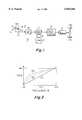
- FIG. 2illustrates possible pedal-position-to-torque transfer characteristics which may be used in accordance with the invention.
- a vehicle 10includes an accelerator pedal (accelerator) 12 hinged about an axis 14.
- Pedal 10is connected to the movable wiper 16m of a resistor 16r of a position sensor 16. More particularly, resistor 16r is connected at one end to ground and at the second end to a source (+) of voltage. Together, resistor 16r and wiper 16m act as a potentiometer, producing a wiper voltage which varies with the amount of depression or position of the pedal 12.
- the voltage representing the pedal positionis applied from sensor 16 analog-to-digital converter (ADC) 20.
- ADCanalog-to-digital converter
- the analog-to-digital converter 20converts the pedal-position voltage into a pedal-position-indicating digital signal.
- the pedal-position-indicating digital signalis applied as an address input to a digital memory 22.
- Memory 22is preprogrammed with at least one page of information representing a conversion from pedal position to motor torque.
- the conversion informationis in the form of a signal associated with each memory position or location which can be addressed by the pedal-position-indicating digital signal.
- the signalsare stored in the memory in such a way that the torque represented by the signal at each address is no less the torque represented by the signal at addresses associated with less depression of the pedal 12.
- FIG. 2illustrates a particular torque-versus-pedal depression plot 210, which may be used as a default characteristic, in which the torque read from memory is linearly related to the pedal depression or pedal position.
- the signal read from memory 22 of FIG. 1is applied to a motor controller illustrated as a block 24.
- Block 24converts the commanded torque into appropriate power signals for a traction motor 26.
- Traction motor 26produces torque in response to the commands from controller 24, and the torque is applied through a differential gearing arrangement (if desired) to one or more drive wheels 30a and 30b.
- the controller of block 24may be of any conventional type, such as are described, for example, in U.S. Pat. No. 5,828,201, issued Oct. 27, 1998 in the name of Hoffman et al. and U.S. Pat. No. 5,869,950, issued Feb. 9, 1999 in the name of Hoffman et al.; allowed patent applications Ser. No. 09/044,669, filed Mar. 20, 1998 in the name of Lyons et al., Ser. No. 09/044,671 filed Mar. 20, 1998 in the name of Lyons et al., and Ser. No. 09/039,895 filed Mar. 16, 1998 in the name of Gataric et al.; and in patent applications Ser. No. 09/192,645, filed Nov.
- a major advantage of the described arrangementis that the "liveliness" or “feel” of the vehicle can be changed to suit the user by simply programming the memory 22 of FIG. 1 with a different sequence of torque values.
- Plot 212 of FIG. 2illustrates a plot which would have a "livelier" feel than plot 210, and use of plot 214 would be livelier still. This change would be manifest because, the torque applied to the wheels would be greater for plots 212 and 214 at a lesser depression of the accelerator pedal 12 than for plot 210. This would result in a greater vehicle acceleration, thereby giving the impression of "more power.”
- a further memory 40(which may actually be a part of memory 22, but which is illustrated separately for simplicity) is illustrated as being connected by a path 42 to memory 22.
- Memory 40accommodates one or more pages of conversion characteristics, such as 212 and 214 of FIG. 2. It is desirable to do any reprogramming of active memory 22 an entire page at a time, so as to avoid having discontinuities in the transfer function as might occur if each memory address of memory 22 were separately loaded by hand, as by selection from a keyboard.
- the loading of the memory 22is always one memory location at a time when conventional memories are used, but when the entire set of values, corresponding to one of plots 210, 212, or 214, is transferred from memory 40 into memory 22 as a result of a single command, so as to overwrite the values previously existing therein, the transfer is instantaneous insofar as a human user is concerned.
- a plot of the transfer characteristicwould not contain a discontinuity due to the length of time required for individual human programming of each separate memory location. This is not to say, however, that the transfer characteristic could not, once loaded into memory 22, cannot have one or more discontinuities, if desired for some particular purpose.
- plots stored in memory 22are illustrated as monotonically increasing in plots 210, 212, and 214, those skilled in the art know that the plots may also be monotonically decreasing, and that appropriate conversion may be made an inherent part of the controller 24.
- the senor 16has been described as an analogue-voltage device requiring an analog-to-digital converter 20, the sensor may instead be a digital position encoder which converts the pedal position directly into a digital signal, without the necessity for a discrete ADC such as 20.
- the memory locationshave been described as sequentially addressed, they may be nonsequential or even in random order, so long as there is a conversion arrangement which converts the pedal position signals into addresses which contain the torque command signals in the desired monotonic sequence.
- having a non-monotonic sequence at the upper end of the torque rangemight be acceptable, so long as the bottom end of the torque range was monotonic.
- a method, for operating an electric vehicle (10)includes the steps of preprogramming a sequence of memory (22) locations of a digital memory (22) associated with the vehicle (10) with torque signals representing the magnitude of the torque which is to be applied to the wheels (30a, 30b) of the vehicle (10) for propulsion thereof.
- the torque signals preprogrammed into the memory (22)represent one of (either) a monotonically increasing and a monotonically decreasing value of torque as a function of sequential addressing of the memory (22) locations, so that sequential addressing of the memory (22) locations results in the reading of signals which either increase or decrease monotonically.
- the methodincludes the production of a position signal representing the position of the accelerator pedal (12) of the vehicle (10), which may be performed by as simple an arrangement as a variable resistor (16r) connected to the pedal (12), or possibly by a position transducer, equivalent to those found in a computer mouse.
- the pedal (12) position signalis converted (ADC 20) into digital address signals, and the digital address signals are applied to the memory (22) for, at any particular time, addressing a memory (22) location corresponding to the current pedal (12) position as currently identified by the digital address signals.
- a traction motor (26) of the vehicle (10)is operated at the corresponding torque.
- the preprogramming stepincludes the step of preprogramming the memory (22) locations with torque signals which increase in magnitude linearly (210) with sequence address.
- the memory (22) locationscan be programmed with values which increase in value nonlinearly (212, 214). The preprogramming can be performed on-the-fly, while the vehicle (10) is in motion.
- a vehicle (10), according to another aspect of the invention,includes a drive wheel (30a, 30b) and an electric traction motor (26) connected to the wheel (30a, 30b).
- a controller (24)is coupled to the motor (26), for driving the motor (26) with electrical power, for causing the motor (26) to produce torque in response to torque command signals applied to the controller (24).
- a digital memory (22)includes a plurality of memory locations. The memory (22) is preprogrammed at a plurality of sequential address locations, over a principal portion of the vehicle (10) control range, with one of (either)monotonically increasing and monotonically decreasing torque command signals.
- An accelerator (12), which may be operated by a vehicle (10) operator,is provided.
- a position sensing transducer (16, 20)is coupled to the accelerator (12), for generating memory (22) address signals in response to the position of the accelerator (12).
- An arrangement (connection 21)couples the memory address signals from the transducer (16, 20) to the memory (22) for addressing memory locations thereof, for thereby producing the torque command signals, for thereby causing the motor (26) to drive the vehicle (10) with torque selected in response to the position of the accelerator.
- the torque signals preprogrammed into the memory (22) at sequentially addressable memory locationsare linearly related (210) to torque, and in another embodiment they are nonlinearly related (212, 214).
Landscapes
- Engineering & Computer Science (AREA)
- Power Engineering (AREA)
- Transportation (AREA)
- Mechanical Engineering (AREA)
- Electric Propulsion And Braking For Vehicles (AREA)
Abstract
Description
Claims (5)
Priority Applications (1)
| Application Number | Priority Date | Filing Date | Title |
|---|---|---|---|
| US09/369,085US6055466A (en) | 1999-08-05 | 1999-08-05 | Vehicle responsiveness in an electric vehicle |
Applications Claiming Priority (1)
| Application Number | Priority Date | Filing Date | Title |
|---|---|---|---|
| US09/369,085US6055466A (en) | 1999-08-05 | 1999-08-05 | Vehicle responsiveness in an electric vehicle |
Publications (1)
| Publication Number | Publication Date |
|---|---|
| US6055466Atrue US6055466A (en) | 2000-04-25 |
Family
ID=23454049
Family Applications (1)
| Application Number | Title | Priority Date | Filing Date |
|---|---|---|---|
| US09/369,085Expired - Fee RelatedUS6055466A (en) | 1999-08-05 | 1999-08-05 | Vehicle responsiveness in an electric vehicle |
Country Status (1)
| Country | Link |
|---|---|
| US (1) | US6055466A (en) |
Cited By (9)
| Publication number | Priority date | Publication date | Assignee | Title |
|---|---|---|---|---|
| US20030196841A1 (en)* | 2002-03-01 | 2003-10-23 | Floor Style Products, Inc. | Power riding trailer for an implement |
| US20040040757A1 (en)* | 2000-12-22 | 2004-03-04 | Christof Scherg | Method for operating a non-railbound land vehicle with a combustion engine-generator unit and an electric drive motor and corresponding vehicle |
| US20060145482A1 (en)* | 2005-01-06 | 2006-07-06 | Bob Roethler | Vehicle powertrain that compensates for a prime mover having slow transient response |
| US20100324763A1 (en)* | 2007-02-27 | 2010-12-23 | Renault S.A.S. | Device for controlling the electric operation mode of a hybrid power unit of a hybrid vehicle by action on the accelerator pedal |
| CN101746415B (en)* | 2008-12-18 | 2011-06-01 | 匡斌 | Electronic differential control system of electric vehicle |
| US20110174561A1 (en)* | 2010-01-21 | 2011-07-21 | ePower Engine Systems, L.L.C. | Hydrocarbon Fueled-Electric Series Hybrid Propulsion Systems |
| EP3162650A1 (en)* | 2015-10-27 | 2017-05-03 | Thunder Power New Energy Vehicle Development Company Limited | Adaptive ev pedal stroke |
| EP3162649A1 (en)* | 2015-10-27 | 2017-05-03 | Thunder Power New Energy Vehicle Development Company Limited | Adaptive ev pedal stroke |
| US9975450B2 (en)* | 2015-10-27 | 2018-05-22 | Thunder Power New Energy Vehicle Development Company Limited | Adaptive EV pedal stroke |
Citations (4)
| Publication number | Priority date | Publication date | Assignee | Title |
|---|---|---|---|---|
| US5418399A (en)* | 1994-01-25 | 1995-05-23 | Klaue; Hermann | Engine/generator set especially for a motor vehicle |
| US5730238A (en)* | 1995-05-24 | 1998-03-24 | Matsushita Electric Industrial Co., Ltd. | Control method of electric car |
| US5828201A (en)* | 1997-10-30 | 1998-10-27 | Lockheed Martin Corporation | Method for maintaining the charge capacity of traction battery modules of a hybrid electric vehicle |
| US5869950A (en)* | 1997-10-30 | 1999-02-09 | Lockheed Martin Corp. | Method for equalizing the voltage of traction battery modules of a hybrid electric vehicle |
- 1999
- 1999-08-05USUS09/369,085patent/US6055466A/ennot_activeExpired - Fee Related
Patent Citations (4)
| Publication number | Priority date | Publication date | Assignee | Title |
|---|---|---|---|---|
| US5418399A (en)* | 1994-01-25 | 1995-05-23 | Klaue; Hermann | Engine/generator set especially for a motor vehicle |
| US5730238A (en)* | 1995-05-24 | 1998-03-24 | Matsushita Electric Industrial Co., Ltd. | Control method of electric car |
| US5828201A (en)* | 1997-10-30 | 1998-10-27 | Lockheed Martin Corporation | Method for maintaining the charge capacity of traction battery modules of a hybrid electric vehicle |
| US5869950A (en)* | 1997-10-30 | 1999-02-09 | Lockheed Martin Corp. | Method for equalizing the voltage of traction battery modules of a hybrid electric vehicle |
Cited By (16)
| Publication number | Priority date | Publication date | Assignee | Title |
|---|---|---|---|---|
| US20040040757A1 (en)* | 2000-12-22 | 2004-03-04 | Christof Scherg | Method for operating a non-railbound land vehicle with a combustion engine-generator unit and an electric drive motor and corresponding vehicle |
| US7163071B2 (en)* | 2000-12-22 | 2007-01-16 | Magnet-Motor Gesellschaft Fur Magnetmotorische Technik Mbh | Method for operating a non-railbound land vehicle with a combustion engine-generator unit and an electric drive motor and corresponding vehicle |
| US20030196841A1 (en)* | 2002-03-01 | 2003-10-23 | Floor Style Products, Inc. | Power riding trailer for an implement |
| US6986397B2 (en)* | 2002-03-01 | 2006-01-17 | Floorstyle Products, Inc. | Power riding trailer for an implement |
| US20060145482A1 (en)* | 2005-01-06 | 2006-07-06 | Bob Roethler | Vehicle powertrain that compensates for a prime mover having slow transient response |
| US20100324763A1 (en)* | 2007-02-27 | 2010-12-23 | Renault S.A.S. | Device for controlling the electric operation mode of a hybrid power unit of a hybrid vehicle by action on the accelerator pedal |
| CN101746415B (en)* | 2008-12-18 | 2011-06-01 | 匡斌 | Electronic differential control system of electric vehicle |
| US8783396B2 (en) | 2010-01-21 | 2014-07-22 | Epower Engine Systems, Llc | Hydrocarbon fueled-electric series hybrid propulsion systems |
| US20110174561A1 (en)* | 2010-01-21 | 2011-07-21 | ePower Engine Systems, L.L.C. | Hydrocarbon Fueled-Electric Series Hybrid Propulsion Systems |
| EP3162650A1 (en)* | 2015-10-27 | 2017-05-03 | Thunder Power New Energy Vehicle Development Company Limited | Adaptive ev pedal stroke |
| EP3162649A1 (en)* | 2015-10-27 | 2017-05-03 | Thunder Power New Energy Vehicle Development Company Limited | Adaptive ev pedal stroke |
| CN106965705A (en)* | 2015-10-27 | 2017-07-21 | 昶洧新能源汽车发展有限公司 | Adaptive Electric Vehicle Pedal Travel |
| CN107042771A (en)* | 2015-10-27 | 2017-08-15 | 昶洧新能源汽车发展有限公司 | Adaptive Electric Vehicle Pedal Travel |
| US9950640B2 (en) | 2015-10-27 | 2018-04-24 | Thunder Power New Energy Vehicle Development Company Limited | Adaptive ev pedal stroke |
| US9975450B2 (en)* | 2015-10-27 | 2018-05-22 | Thunder Power New Energy Vehicle Development Company Limited | Adaptive EV pedal stroke |
| US10173550B2 (en) | 2015-10-27 | 2019-01-08 | Thunder Power New Energy Vehicle Development Company Limited | Adaptive EV pedal stroke |
Similar Documents
| Publication | Publication Date | Title |
|---|---|---|
| US4829221A (en) | Method of controlling a motor-driven clutch | |
| US6055466A (en) | Vehicle responsiveness in an electric vehicle | |
| US4691676A (en) | Apparatus for throttle valve control | |
| US5084821A (en) | Apparatus for determining control characteristics for automobiles and system therefor | |
| US5351776A (en) | Electronic system for a motor vehicle | |
| US6021370A (en) | Vehicle/engine acceleration rate management system | |
| US4555651A (en) | Motor speed control apparatus | |
| GB2454338A (en) | Torque control based on driving mode and accelerator pedal position. | |
| US20080006462A1 (en) | Method and arrangement for the speed control of a motor vehicle and operator-controlled element | |
| EP0825102A3 (en) | Torque limiting device for motors in electrically driven vehicles | |
| US5994859A (en) | Torsional oscillation compensation in the drivetrain of a motor vehicle | |
| JP2022030834A (en) | Electric car | |
| US20040097327A1 (en) | Method for setting a desired operating state of a hybrid drive of a vehicle | |
| CA2256264A1 (en) | Throttle controller for limiting degree of opening of throttle in stall state | |
| US5821720A (en) | Backlash elimination in the drivetrain of an electric vehicle | |
| JPS62275844A (en) | Vehicle traction control and constant speed control equipment | |
| US7142964B2 (en) | Electric power steering control device | |
| JP3381338B2 (en) | Motor control device for hybrid vehicle | |
| JP2001107766A (en) | Vehicle characterization device | |
| EP0408767A4 (en) | Engine output controller | |
| JP2896380B2 (en) | AT vehicle transmission | |
| US11565667B1 (en) | Automatic brake pedal control | |
| JPH0623018B2 (en) | Vehicle throttle control device | |
| JP2000104576A (en) | Automotive power transmission device and control method thereof | |
| JP2002054471A (en) | Engine rotation control device for work vehicle |
Legal Events
| Date | Code | Title | Description |
|---|---|---|---|
| AS | Assignment | Owner name:LOCKHEED MARTIN CORPORATION, PENNSYLVANIA Free format text:ASSIGNMENT OF ASSIGNORS INTEREST;ASSIGNOR:GREWE, TIMOTHY MICHAEL;REEL/FRAME:010158/0336 Effective date:19990802 | |
| FEPP | Fee payment procedure | Free format text:PAYOR NUMBER ASSIGNED (ORIGINAL EVENT CODE: ASPN); ENTITY STATUS OF PATENT OWNER: LARGE ENTITY | |
| AS | Assignment | Owner name:BAE SYSTEMS CONTROLS INC., NEW YORK Free format text:ASSIGNMENT OF ASSIGNORS INTEREST;ASSIGNOR:LOCKHEED MARTIN CORPORATION, A MARYLAND CORPORATION;REEL/FRAME:011783/0001 Effective date:20000925 | |
| FPAY | Fee payment | Year of fee payment:4 | |
| FEPP | Fee payment procedure | Free format text:PAYER NUMBER DE-ASSIGNED (ORIGINAL EVENT CODE: RMPN); ENTITY STATUS OF PATENT OWNER: LARGE ENTITY Free format text:PAYOR NUMBER ASSIGNED (ORIGINAL EVENT CODE: ASPN); ENTITY STATUS OF PATENT OWNER: LARGE ENTITY | |
| FPAY | Fee payment | Year of fee payment:8 | |
| REMI | Maintenance fee reminder mailed | ||
| REMI | Maintenance fee reminder mailed | ||
| LAPS | Lapse for failure to pay maintenance fees | ||
| STCH | Information on status: patent discontinuation | Free format text:PATENT EXPIRED DUE TO NONPAYMENT OF MAINTENANCE FEES UNDER 37 CFR 1.362 | |
| FP | Lapsed due to failure to pay maintenance fee | Effective date:20120425 |