US6054993A - Chroma-keyed specular texture mapping in a graphics processor - Google Patents
Chroma-keyed specular texture mapping in a graphics processorDownload PDFInfo
- Publication number
- US6054993A US6054993AUS08/932,402US93240297AUS6054993AUS 6054993 AUS6054993 AUS 6054993AUS 93240297 AUS93240297 AUS 93240297AUS 6054993 AUS6054993 AUS 6054993A
- Authority
- US
- United States
- Prior art keywords
- color
- range
- texel
- value
- logic
- Prior art date
- Legal status (The legal status is an assumption and is not a legal conclusion. Google has not performed a legal analysis and makes no representation as to the accuracy of the status listed.)
- Expired - Lifetime
Links
Images


Classifications
- G—PHYSICS
- G06—COMPUTING OR CALCULATING; COUNTING
- G06T—IMAGE DATA PROCESSING OR GENERATION, IN GENERAL
- G06T15/00—3D [Three Dimensional] image rendering
- G06T15/50—Lighting effects
- G06T15/506—Illumination models
Definitions
- the present inventionrelates generally to a graphics system for a personal computer. More particularly, the present invention relates to a method and apparatus for applying specular highlighting to pixels in a polygon. Still more particularly, the present invention relates to an improved method of applying specular highlighting to a polygon based on color values in a texture map.
- Sophisticated graphics packageshave been used for some time in expensive computer aided drafting, design and simulation systems. Increased capabilities of graphic controllers and display systems, combined with standardized graphics languages, have made complex graphics functions available in even the most routine applications. For example, word processors, spread sheets and desktop publishing packages now include relatively sophisticated graphics capabilities. Three-dimensional (3D) displays have become common in games, animation, and multimedia communication and drawing packages.
- a set of orthogonal or horizontal scan lineseach comprising a row of pixels, forms an array or grid of pixels to represent the entire screen area.
- the screenpreferably comprises a cathode ray tube (CRT), LCD display, or the like, capable of scanning the entire pixel grid at a relatively high rate to reduce flicker.
- the pixel datapreferably is stored in a frame buffer comprising dynamic random access memories (DRAM's), or more preferably video RAMs (VRAM's), where each pixel is represented by one or more bits depending upon the desired resolution.
- DRAM'sdynamic random access memories
- VRAM'svideo RAMs
- each pixelis drawn or "rendered" with 24 bits of color information (8 bits for red, 8 bits for green, 8 bits for blue).
- Typical display systemsare capable of drawing screens with multiple colors at a variety of screen resolutions, including resolutions of 640 pixels ⁇ 480 pixels, 800 ⁇ 600, 1024 ⁇ 768, 1280 ⁇ 1024, or even higher pixel value combinations, depending upon the software drivers and the hardware used.
- a video controllerscans and converts the pixel data in the frame buffer to provide control signals for the screen system.
- the video controllerrenders the screen pixels, typically from the top of the screen to the bottom and from left to right, converting pixel data into color intensity values for each pixel.
- three separate beamsare controlled for each of the primary colors, where the intensity of each of the beams is determined by the pixel value corresponding to the respective colors.
- a similar systemis used for LCD displays.
- Graphics processors and acceleratorsare available with software drivers that interface the host central processing unit (CPU) to the graphics processor.
- objects to be drawn on the screenare represented by one or more polygons.
- Each polygonis further represented by one or more triangles.
- the software driverreceives information for drawing the triangles on the screen, calculates certain basic parameters associated with the triangles and provides these parameters to the graphics processor.
- the software driverthen sends a command for the graphics processor to draw the triangle into the frame buffer.
- a graphics processormay use interpolation techniques in which the fundamental information for the triangle to be drawn comprises a set of initial and incremental parameters.
- the graphics processorloads or otherwise receives the initial parameters for rendering a first pixel, and then interpolates the remaining pixels in a triangle by using the incremented parameters until the triangle is complete.
- Texture mapping techniquesgenerally apply a bitmapped texture image to a polygon on the screen.
- a texture maptypically is a two dimensional array of texture elements ("texels") that define a texture such as a brick, a carpet design, the grain of wood or any other texture that might be applied to an object on a computer screen.
- a graphics processormay apply glare, or specular highlight, to an object.
- the front wall 20 of a jail cellincludes numerous vertical bars 22 and one or more horizontal bars 24, as well as a door 21.
- Each bartypically is drawn to give the appearance of metal.
- the barsare drawn to create the appearance of light reflecting off the bars by adding a specular component to the texel color values of the bars.
- specular highlightingby adding white, or some other appropriate color, to the texel value to be applied to pixels on bars 22, 24.
- the amount of specular highlightingcan be varied by varying the intensity of the specular component applied to a particular texel value.
- objects drawn on the screentypically are represented by one or more triangles.
- graphics systemsapply specular highlighting on a triangle-by-triangle basis and to every pixel within a triangle. Such systems, therefore, must define triangles for those portions of a polygon to receive specular highlighting.
- specular highlightingis to be applied only to the bars 22, 24, each bar must be represented with two or more triangles, as illustrated by triangles 32, 34 in FIG. 2.
- the number of triangles to represent those surfacesnecessarily also increases.
- jail cell wall 20could be represented by relatively few triangles, such as by two triangles 25, 26 separated by dashed line 28.
- a texture map representing the wall including the bars 22, 24 and door 21could then be applied to triangles 25, 26.
- specular highlighting techniquesapply specular highlighting to every pixel in jail cell wall 20, without distinguishing the dark regions 27 between the bars where no specular highlighting is appropriate. The need for specular highlighting thus requires the jail cell wall 20 to be divided into numerous triangles.
- a downside of conventional specular highlighting techniquesis that objects often must be rendered with more triangles than otherwise would be required. An increase in the number of triangles required to render an object places a heavier demand on the system memory and processor.
- a graphic processoruses a number of parameters to represent each triangle. As the number or triangles required for specular highlighting increases, so does the number of parameters required to represent the triangles. As a result, more memory is required to store the parameters representing the triangles. Further, a greater processing demand is placed on the graphics processor to render a larger number of triangles required by specular highlighting.
- the problems outlined aboveare in large part solved by a graphics processor of the present invention.
- the graphics systemincludes a graphics controller for rendering polygons with specular highlighting (glare) based on a comparison of texel color values to a predefined range of color values.
- the predefined range of color values used in the comparisoncorresponds to the range of colors of those portions of a texture for which specular highlighting is appropriate, such as metallic surfaces off which light reflects. If the texel color value to be applied to a texel is within the range of color values, a specular component is added to the texel value before the texel value is used to render a pixel on a computer screen.
- the determination as to whether to add specular highlighting to a pixelis performed on a pixel-by-pixel basis.
- objectscan be represented and rendered with fewer triangles because no triangles are needed just for specular highlighting.
- the graphics processorincludes multiple range registers for storing the range of color values and color comparators for comparing the texel color value to the range of colors stored in the range registers.
- Multiplexer logiccoupled to the color comparators determines whether the texel color value is within the range of color values for which specular highlighting is appropriate.
- the multiplexer logicasserts a control signal dependent on whether the texel color value is within the range.
- the control signalis provided to a multiplexer which selects one of two input signals to be provided as an output signal. One input signal represents the texel color value and the other input signal represents the texel color value combined with a specular highlight component.
- the output signal from the multiplexeris used by the graphics processor to render a pixel.
- FIG. 1shows an exemplary image of the jail cell wall including multiple metal bars
- FIG. 2shows a single metal bar of FIG. 1 represented by two triangles on which glare, or specular highlighting is applied;
- FIG. 3shows a block diagram of the graphics system including a graphics processor in accordance with the preferred embodiment
- FIG. 4is a block diagram of the graphics processor of FIG. 3 including a texture map engine in accordance with the preferred embodiment
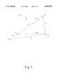
- FIG. 5shows an exemplary triangle used to represent objects by the graphics processor of FIG. 4;
- FIG. 6depicts texture elements from a texture map used to render texture
- FIG. 7shows a more detailed block diagram including color compare logic of the texture map engine of FIG. 4.
- FIG. 8shows a schematic of the color compare logic shown in FIG. 7.
- a computer system 100 constructed in accordance with the preferred embodimentgenerally includes CPU 102, system memory 104, a peripheral computer interconnect (“PCI”) bridge and memory controller 106, a graphics processor 120, and a display 114.
- the CPU 102, system memory 104, PCI bridge 106 and display 114preferably are known components.
- the CPU 102may include any available processor such as the Pentium MMX®, K6®, or any other processor capable of operating a computer system in a fashion consistent with the preferred embodiment.
- the system memory 104preferably includes standard dynamic random access memory (“DRAM”), synchronous DRAM (SDRAM), or any other suitable type of memory.
- the PCI bridge and memory controllermay include any suitable off-the-shelf device or may be a custom design.
- Display 114includes standard cathode ray tube (“CRT”) displays, flat panel displays, or any other display device capable of displaying graphics.
- CTRcathode ray tube
- the CPU 102connects to the PCI bridge and memory controller 106 via a host bus 108 which includes address, data, and control lines for transferring data.
- the PCI bridge and memory controller 106also connects to system memory 104 via a memory bus 110 which also includes address, data, and control lines suitable for transferring data between system memory 104 and PCI bridge and memory controller 106.
- the CPU 102may initiate read and write cycles to system memory 104 by way of host bus 108, PCI bridge and memory controller 106, and memory bus 110 according to known techniques.
- a system bus 112preferably comprising a PCI bus (although other bus architectures are also acceptable) connects the PCI bridge and memory controller 106 to graphics processor 120. It should be recognized by those of ordinary skill in the art that other devices besides those shown in FIG. 3 may also connect to the PCI bus 112. Examples of other devices include extended memory cards, video cards, and network cards. Graphics data in the form of a display list is transferred between CPU 102 and graphics processor 120 by way of host bus 108, PCI bridge and memory controller 106, and PCI bus 112. Once graphics data is received by the graphics processor 120 over the PCI bus 112, the graphics processor manipulates the data to provide appropriate signals over lines 116 to display 114 for displaying objects on the display.
- PCI buspreferably comprising a PCI bus (although other bus architectures are also acceptable) connects the PCI bridge and memory controller 106 to graphics processor 120. It should be recognized by those of ordinary skill in the art that other devices besides those shown in FIG. 3 may also connect to the PCI bus 112. Examples of other devices
- the graphics processor 120 of the preferred embodimentincludes a PCI interface 122, a polygon engine 124, a texture map engine 126, and a display interface 132.
- the PCI interface 122, polygon engine 124, and texture map engine 126couple together via bus 128 which preferably comprises a host interface (HEF) bus.
- the polygon engine 124 and the texture map engine 126couple to the display interface 132 via bus 130.
- the display interface 132uses the information provided to it from the polygon engine 124 and the texture map engine 126 to provide appropriate signals to display 114 over lines 116.
- graphics processor 120receives data in the form of a display list from the CPU 102 or system memory 104 via the PCI bus 112.
- the display listis stored in a register file in graphics processor 120 or memory (not shown) directly coupled to the graphics processor 120.
- the display listincludes all information needed to draw a polygon. As explained in greater detail below, some of the values from the display list are used by the polygon engine 124 and some values are used by the texture map engine 126. It is assumed each polygon includes an upper or main triangle (such as triangle 47 in FIG. 1) abutting a lower or opposite triangle (such as triangle 49).
- the values in the display listinclude the data needed to render both upper and lower triangles.
- Table I belowincludes an exemplary display list identifying the values that are included in the list (first column of Table I) and the description of each value (second column).
- References to X and Y valuesrefer to the x, y coordinates of pixels on the display (referred to as x, y pixel space).
- References to U and V valuesrefer to the coordinates of texels in a texture map which are identified as u,v coordinates.
- the u, v coordinate system of a texture mapis referred to as u, v texture map space.
- references to SPEC valuesrefer to specular highlighting and are used in accordance with a preferred embodiment of the invention described below.
- a display listmay, and often will, include additional values such as second order u and v slope values used for providing perspective when applying a texture map to a polygon.
- additional valuessuch as second order u and v slope values used for providing perspective when applying a texture map to a polygon.
- the values in the display list of Table Iare exemplary only and are not exhaustive of all the values included in a typical display list.
- the graphics processor 120uses the values in the display list in Table I to draw a polygon and apply texture.
- the manner in which the graphics processor 120 renders a textured polygonwill now be described with reference to FIG. 5 and Table I.
- a typical polygon 30is shown in FIG. 5.
- the polygon 30preferably is divided into two portions--an upper or main triangle 47 and a lower or opposite triangle 49 separated from main triangle 47 by horizontal dashed line 48.
- a polygonis subdivided into as many triangles as are necessary to represent the polygon. For example, ten thousand triangles or more may be required to create a realistic looking image of a human face.
- Graphics objectstypically are represented with a collection of triangles because triangles are simple geometric shapes that can be characterized with relatively few values as explained below.
- polygon 30may be drawn as two triangles, such as triangles 47, 49.
- a software driverreceives vertex information (including x, y coordinates of each vertex 41, 42, 43) and identifies a main slope line 45 extending the vertical length (in the y direction) of polygon 30 between vertices 41 and 43.
- the other two sides 51, 53 of polygon 30are referred to as opposite slopes.
- the polygon 30is interpolated using orthogonal (ORTHO) horizontal scan lines of pixels that extend from the main slope 45 to the opposite edges 51, 53.
- the vertical or y parameteris used as a reference coordinate, so that the y pixel value preferably is incremented (or decremented depending on whether the triangle is rendered from top to bottom or bottom to top) by one for each scan line.
- a value for the main slope 45is calculated as an initial condition and is used to compute the x coordinate of the first pixel in each can line (ie., the pixels on of the main slope).
- Initial and incremental width valuesare determined or the scan lines and the graphics processor intepolates the width rather than edge walking the opposite slopes.
- the interpolated width valueis loaded into a counter and decremented for each pixel in the current scan line. When the width counter becomes zero or otherwise reaches terminal count, the counter asserts a terminal count signal indicating that the scan line is complete.
- each triangle 47, 49is drawn one row or horizontal scan line of pixels at a time. For each scan line, pixels are rendered from the main slope 45 to the opposite edges 51, 53.
- Polygon 30is drawn from top to bottom.
- Polygon 30is drawn in a series of horizontal ORTHO scan lines in which each scan line includes one or more pixels. Because the ORTHO scan lines are horizontal, only the x coordinate changes from one pixel in the scan line to the next.
- the polygon engine 124preferably increments the x coordinate by one as the graphics processor renders each pixel in succession along an ORTHO scan line.
- the graphics processorneeds to know or calculate the coordinate of the first pixel in the triangle (pixel 41, for example), the coordinate of the first pixel in each ORTHO scan line, the number of pixels in each scan line, and the number of scan lines in the triangle as described above.
- the coordinate of the initial pixelis X, Y.
- the coordinate of the first pixel in each successive scan lineis calculated by adding ⁇ X MAIN to X.
- ⁇ X MAINmay be a positive or negative number depending on the slope of the line on which the first pixels in each ORTHO scan line lie.
- ⁇ X MAINis a negative number because the x, y coordinate axes in the preferred embodiment have x coordinates increasing from left to right (y coordinates increase from the top of the display to the bottom).
- ⁇ X MAINif the line on which the first pixels lie slopes down and to the right, ⁇ X MAIN will be a positive number. If the line is vertical, ⁇ X MAIN has a value of 0.
- the number of pixels in each ORTHO scan lineis calculated by adding ⁇ X WIDTH MAIN to the width (i.e., number of pixels in the x direction) of the previous scan line.
- the number of scan lines in a triangleis provided by the Y COUNT value which includes the number of scan lines in both the upper (main) triangle and lower (opposite) triangle.
- the portion of the Y COUNT value representing the number of scan lines in the main trianglepreferably is loaded into a counter and decremented by one for each ORTHO scan line drawn. When the counter reaches its terminal count, the graphics processor has completed drawing the main triangle.
- the first pixel to be drawnpreferably is pixel 39 and the width of the first scan line is the number of pixels along dashed line 48.
- the texture map engine 126applies a texture value (texels) to each pixel in the triangles drawn by polygon engine 124.
- the texelsare stored in a texture map and are accessed using values in the display list in Table I above. It should be apparent that in x, y pixel space polygons are drawn by providing color values to each and every pixel in an ORTHO scan line, incrementing they coordinate to the next scan line and repeating the process.
- both the u and v coordinatemay change from one texel to the next along a single ORTHO scan line in texture space.
- the U and V values from Table Iprovide the coordinate of the first texel to be used from the texture map.
- the ⁇ U ORTHO and ⁇ V ORTHO valuesare used to calculate the u, v coordinate for each texel along an ORTHO scan line.
- the ⁇ U MAIN and ⁇ V MAIN valuesare used to compute the u, v coordinate for the first texel in a particular ORTHO scan line.
- exemplary texels 140, 142, 144, 146, 148, 149 from a texture mapare shown in relation to the u and v axes.
- Texels 140, 142, 144are texels along ORTHO scan line 160 and texels 146, 148, 149 are texels along ORTHO scan line 170.
- the u, v coordinate for texel 142is calculated by adding the ⁇ U ORTHO and ⁇ V ORTHO values to the u, v coordinate of texel 140.
- the u, v coordinate of texel 144is calculated in a similar fashion by adding the ⁇ U ORTHO and ⁇ V ORTHO values to the u, v coordinate of texel 142.
- the first texel (texel 146) on the next scan line (scan line 170)is determined by adding the ⁇ U MAIN and ⁇ V MAIN values to the u, v coordinate of texel 140.
- texture map engine 126must retain the u, v coordinate of the first texel in a scan line until the first texel in the next scan line is calculated.
- polygon engine 126preferably includes color compare logic 200, summing logic 192, and multiplexer 194. It should be recognized that other components will be included in texture map engine 126, but are not shown for sake of clarity. Further, the logic components shown in FIG. 7 need not be included in texture map engine 126, but may be located elsewhere within graphics processor 120.
- a texel value on lines 180 from a texture map 70is provided to color compare logic 200, in accordance with the preferred embodiment described above. Upper and lower color range values are provided via HIF bus 128 to color compare logic 200.
- the color compare logic 200compares the texel value from texel map 70 to the color range values and determines whether the texel value is within the range defined by the color range values, as described in greater detail below.
- the range of color valuesis set to represent the range of values for which specular highlighting would be desired, such as the metallic color of the bars in FIG. 1.
- the output of the color compare logic on line 182comprises a control signal for multiplexer 194.
- the texel value from texel map 70is provided to the "0" input of multiplexer 194.
- Summing logic 192adds the texel value on lines 180 from texel map 70 to a specular component value on lines 181 preferably generated by the texture map engine.
- the output of summing logic 192i.e, the texel color value combined with a specular component, is provided on lines 193 to the "1" input of multiplexer 194.
- the output control signal on line 182 from the color compare logic 200controls which of the two input signals to the multiplexer 194 is provided as an output signal from the multiplexer on lines 197.
- a high logic value for the control signal on line 182selects the "1" input of multiplexer 194, thereby providing the specularized texture value from the summing logic 192 as the output signals on lines 197.
- a low logic value on control line 182directs multiplexer 194 to select the "0" input (ie., the texel color value without a specular component) as the output signals on lines 197 from the multiplexer 194.
- Color compare logic 200thus determines whether to add a specular component value to a texel value from a texture map. This determination is made by comparing the texel value to a range of color values corresponding to colors for which specular highlighting is appropriate.
- the range of color valuescan be predetermined or programmed by the user or application software according to known techniques.
- the graphics processor of the preferred embodimentdetermines whether to apply specular highlighting on a pixel-by-pixel basis.
- the color compare logic 200preferably includes color range registers 331, 333, 341, 343, 351, and 353, color comparators 334, 336, 344, 346, 354, 356, color range logic 335, 345, 355, and multiplexer logic 360.
- the graphics processor 120loads color range values into color range registers 331-353. Upper and lower limits which define the range for each of the three primary colors, blue, green, and red are loaded into range registers 331-353 by the graphics processor 120.
- graphics processor 120loads a lower range value for red into a red low range register 331 and a high range value for red into a red high range register 333.
- the graphics processor 120loads low range and a high range values for green into registers 341 and 343, respectively, and low range and high range color values for blue into range registers 351 and 353, respectively.
- the color comparators 334-356compare the color of the texel value on lines 180 with the low and high range values for each of the colors red, blue, and green. Color in a graphics system generally are represented by a combination of red, green and blue. Accordingly, each texel color value on lines 180 includes a red value, a green value and a blue value. In accordance with the preferred embodiments, color comparator 334 determines whether the red component of the texel value on lines 180 is greater than or equal to the low range color value for red stored in range register 331.
- the greater than (GT) output signal from color comparator 334thus is asserted if the red component of the texel value on lines 180 is greater than the low range value for red stored in range register 331. If, however, the red component of the texel value is equal to the low range red value, then the equal to (EQ) output signal from color comparator 334 is asserted.
- Color comparator 336determines whether the red component of the texel value is less than or equal to the high range red color value stored in range register 333. The less than (LT) output signal from comparator 336 is asserted if the red component of the texel value is greater than the high range red value of range register 333.
- red texel valueis equal to the high range value in register 333, then the EQ output signal from comparator 336 is asserted.
- the four output signals from red comparators 334, 336are provided to red range logic 335 which then determines whether the red texel value is within the range of colors defined by range registers 331 and 333.
- the output signal from red range logic 335 on line 337is asserted if, in fact, the red texel value is within the range defined by range registers 331, 333.
- comparators 344 and 346determine whether the green texel value on lines 180 is within the range of green color values defined green range registers 341, 343. If the green texel value is within the range defined by range registers 341, 343, as determined by comparators 344, 346, the green range logic 345 asserts its output signal on line 347 so indicating.
- Blue color comparators 354 and 356 and blue range logic 355determine whether the blue texel value is within the range of color values defined by low and high blue range registers 351, 353. Blue range logic 355 asserts an output signal on line 357 indicating whether the blue texel value on lines 180 is within the range of values defined by blue range registers 351, 353.
- Multiplexer logic 360receives the output signals on lines 337, 347, 357 from the red, green and blue range logic 335, 345, 355 and determines whether all three color components of the texel value on lines 180 are within their respective range limits defined by range registers 331-353. If the multiplexer logic 360 determines that all three color components of a texel value are within the range of colors defined by the range registers, it asserts the output control signal on line 182 which controls multiplexer 194 as described previously with respect to FIG. 7.
- the graphics processor 120determines whether to apply a specular component to a texel color value by comparing the texel color value to a range of color values defined by range registers 331-353.
- the range of color valuesare predetermined to correspond to the surfaces in an object rendered on the screen for which specular highlighting is appropriate.
- metal bars 22, 24 and door 21are represented by one or more texture maps, and preferably only one texture map.
- the range of colors defined by the color range registerspreferably include the color values of the texels comprising the metal bars 22, 24 and door 21, and do not include the color values of the texels representing the spaces 27 between the bars.
- specular highlightingis applied only on the bars 22, 24 and door 21 as is desired.
- Applying specular highlighting in accordance with the preferred embodiment of the inventionallows objects, such as the jail cell wall 20 of FIG. 1, to be rendered with fewer triangles than previously possible because the invention does not require triangles to be defined for those portions of an object for which specular highlighting is desired.
Landscapes
- Engineering & Computer Science (AREA)
- Computer Graphics (AREA)
- Physics & Mathematics (AREA)
- General Physics & Mathematics (AREA)
- Theoretical Computer Science (AREA)
- Image Generation (AREA)
Abstract
Description
TABLE I ______________________________________ Display List NAME DESCRIPTION ______________________________________ X Initial x pixel coordinate Y Initial y pixel coordinate R Initial Red value for initial x, y pixel G Initial Green value for initial x, y pixel B Initial Blue value for initial x, y pixel ΔX MAIN Main slope value: this value is added to the initial x coordinate on each step in y to generate the x starting point for each new ORTHO scan line. Y COUNT Top count: Bottom count concatenated. Determine the number of steps in y for the upper and lower portions of the triangle drawn. X WIDTH Initial upper width value. Width of the first ORTHO scan MAIN line in x of the upper (main) triangle X WIDTH Initial bottom width value. Width of the first ORTHO scan OPP line in x of the lower (opposite) triangle ΔX WIDTH Main width slope. This value is the amount by which MAIN the width of each scan line in x of the upper (main) triangle is adjusted on each step in y. ΔX WIDTH Opposite width slope. This value is the amount by which OPP the width of each scan line in x of the lower (opposite) triangle is adjusted on each step in y. ΔR MAIN Red main slope. This value is the amount by which the red color component start value for each scan line in x is adjusted on each step in y. ΔG MAIN Green main slope. This value is the amount by which the green color component start value for each scan line in x is adjusted on each step in y. ΔB MAIN Blue main slope. This value is the amount by which the blue color component start value for each scan line in x is adjusted on each step in y. ΔR ORTHO Red ORTHO slope. This value is the amount by which the red color component is adjusted for each step in x along a scan line. ΔG ORTHO Green ORTHO slope. This value is the amount by which the green color component is adjusted for each step in x along a scan line. ΔB ORTHO Blue ORTHO slope. This value is the amount by which the blue color component is adjusted for each step in x along a scan line. Z Initial z pixel coordinate. ΔZ MAIN Z main slope value. Added to z to generate starting z coordinate for each new scan line. ΔZ ORTHO Z ORTHO value. This value is the amount by which the z coordinate is adjusted along a scan line on each step in x. V Initial v coordinate of first texel address in texture map being used. U Initial u coordinate of first texel address in texture map being used. ΔV MAIN V main slope value. Amount by which the v texel coordinate start value is adjusted on each step in y. ΔU MAIN U main slope value. Amount by which the u texel coordinate start value is adjusted on each step in y. ΔV ORTHO V ORTHO slope value. Amount by which the v texel coordinate is adjusted on each step in x. ΔU ORTHO U ORTHO slope value. Amount by which the u texel coordinate is adjusted on each step in x. R SPEC Initial red specular value. G SPEC Initial green specular value. B SPEC Initial blue specular value. ΔR SPEC Red main delta value MAIN ΔG SPEC Green main delta value MAIN ΔB SPEC Blue main delta value MAIN R SPEC Red Ortho delta value ORTHO G SPEC Green Ortho delta value ORTHO B SPEC Blue Ortho delta value ORTHO ______________________________________
Claims (18)
Priority Applications (3)
| Application Number | Priority Date | Filing Date | Title |
|---|---|---|---|
| US08/932,402US6054993A (en) | 1997-09-17 | 1997-09-17 | Chroma-keyed specular texture mapping in a graphics processor |
| AU89100/98AAU8910098A (en) | 1997-09-17 | 1998-08-17 | Chroma-keyed specular texture mapping in a graphics processor |
| PCT/US1998/017007WO1999014710A1 (en) | 1997-09-17 | 1998-08-17 | Chroma-keyed specular texture mapping in a graphics processor |
Applications Claiming Priority (1)
| Application Number | Priority Date | Filing Date | Title |
|---|---|---|---|
| US08/932,402US6054993A (en) | 1997-09-17 | 1997-09-17 | Chroma-keyed specular texture mapping in a graphics processor |
Publications (1)
| Publication Number | Publication Date |
|---|---|
| US6054993Atrue US6054993A (en) | 2000-04-25 |
Family
ID=25462250
Family Applications (1)
| Application Number | Title | Priority Date | Filing Date |
|---|---|---|---|
| US08/932,402Expired - LifetimeUS6054993A (en) | 1997-09-17 | 1997-09-17 | Chroma-keyed specular texture mapping in a graphics processor |
Country Status (3)
| Country | Link |
|---|---|
| US (1) | US6054993A (en) |
| AU (1) | AU8910098A (en) |
| WO (1) | WO1999014710A1 (en) |
Cited By (23)
| Publication number | Priority date | Publication date | Assignee | Title |
|---|---|---|---|---|
| US6259455B1 (en)* | 1998-06-30 | 2001-07-10 | Cirrus Logic, Inc. | Method and apparatus for applying specular highlighting with specular components included with texture maps |
| US20030001857A1 (en)* | 2001-06-29 | 2003-01-02 | Doyle Peter L. | Method and apparatus for determining logical texture coordinate bindings |
| US6618048B1 (en) | 1999-10-28 | 2003-09-09 | Nintendo Co., Ltd. | 3D graphics rendering system for performing Z value clamping in near-Z range to maximize scene resolution of visually important Z components |
| US20030184556A1 (en)* | 2000-06-02 | 2003-10-02 | Nintendo Co., Ltd. | Variable bit field color encoding |
| US6636214B1 (en) | 2000-08-23 | 2003-10-21 | Nintendo Co., Ltd. | Method and apparatus for dynamically reconfiguring the order of hidden surface processing based on rendering mode |
| US6700586B1 (en) | 2000-08-23 | 2004-03-02 | Nintendo Co., Ltd. | Low cost graphics with stitching processing hardware support for skeletal animation |
| US20040042654A1 (en)* | 2002-08-30 | 2004-03-04 | Benoit Sevigny | Accelerated matte |
| US6707458B1 (en) | 2000-08-23 | 2004-03-16 | Nintendo Co., Ltd. | Method and apparatus for texture tiling in a graphics system |
| US6717577B1 (en) | 1999-10-28 | 2004-04-06 | Nintendo Co., Ltd. | Vertex cache for 3D computer graphics |
| US6774896B2 (en)* | 1997-05-26 | 2004-08-10 | Sony Computer Entertainment, Inc. | Method and apparatus for generating image data by modulating texture data with color data and brightness data |
| US6811489B1 (en) | 2000-08-23 | 2004-11-02 | Nintendo Co., Ltd. | Controller interface for a graphics system |
| US6867781B1 (en) | 2000-08-23 | 2005-03-15 | Nintendo Co., Ltd. | Graphics pipeline token synchronization |
| US7002591B1 (en) | 2000-08-23 | 2006-02-21 | Nintendo Co., Ltd. | Method and apparatus for interleaved processing of direct and indirect texture coordinates in a graphics system |
| US7034828B1 (en) | 2000-08-23 | 2006-04-25 | Nintendo Co., Ltd. | Recirculating shade tree blender for a graphics system |
| US7061502B1 (en) | 2000-08-23 | 2006-06-13 | Nintendo Co., Ltd. | Method and apparatus for providing logical combination of N alpha operations within a graphics system |
| US7075545B2 (en) | 2000-08-23 | 2006-07-11 | Nintendo Co., Ltd. | Graphics system with embedded frame buffer having reconfigurable pixel formats |
| US7184059B1 (en) | 2000-08-23 | 2007-02-27 | Nintendo Co., Ltd. | Graphics system with copy out conversions between embedded frame buffer and main memory |
| US7196710B1 (en) | 2000-08-23 | 2007-03-27 | Nintendo Co., Ltd. | Method and apparatus for buffering graphics data in a graphics system |
| US7205999B2 (en) | 2000-08-23 | 2007-04-17 | Nintendo Co., Ltd. | Method and apparatus for environment-mapped bump-mapping in a graphics system |
| US7307640B2 (en) | 2000-08-23 | 2007-12-11 | Nintendo Co., Ltd. | Method and apparatus for efficient generation of texture coordinate displacements for implementing emboss-style bump mapping in a graphics rendering system |
| US7538772B1 (en) | 2000-08-23 | 2009-05-26 | Nintendo Co., Ltd. | Graphics processing system with enhanced memory controller |
| US7576748B2 (en) | 2000-11-28 | 2009-08-18 | Nintendo Co. Ltd. | Graphics system with embedded frame butter having reconfigurable pixel formats |
| US20130002739A1 (en)* | 2011-06-29 | 2013-01-03 | Chung-Hui Kuo | Depositing job-specified texture on receiver |
Families Citing this family (1)
| Publication number | Priority date | Publication date | Assignee | Title |
|---|---|---|---|---|
| US5963604A (en)* | 1995-11-13 | 1999-10-05 | National Semiconductor Corp. | Communication signal receiver with sampling frequency control |
Citations (28)
| Publication number | Priority date | Publication date | Assignee | Title |
|---|---|---|---|---|
| US4583185A (en)* | 1983-10-28 | 1986-04-15 | General Electric Company | Incremental terrain image generation |
| US4586038A (en)* | 1983-12-12 | 1986-04-29 | General Electric Company | True-perspective texture/shading processor |
| US4692880A (en)* | 1985-11-15 | 1987-09-08 | General Electric Company | Memory efficient cell texturing for advanced video object generator |
| US4714428A (en)* | 1985-12-19 | 1987-12-22 | General Electric Company | Method of comprehensive distortion correction for a computer image generation system |
| US4715005A (en)* | 1984-08-08 | 1987-12-22 | General Electric Company | Terrain/seascape image generator with math model data base |
| US4727365A (en)* | 1983-08-30 | 1988-02-23 | General Electric Company | Advanced video object generator |
| US4811245A (en)* | 1985-12-19 | 1989-03-07 | General Electric Company | Method of edge smoothing for a computer image generation system |
| US4821212A (en)* | 1984-08-08 | 1989-04-11 | General Electric Company | Three dimensional texture generator for computed terrain images |
| US4825391A (en)* | 1987-07-20 | 1989-04-25 | General Electric Company | Depth buffer priority processing for real time computer image generating systems |
| US4855937A (en)* | 1984-08-08 | 1989-08-08 | General Electric Company | Data block processing for fast image generation |
| US4862388A (en)* | 1986-12-15 | 1989-08-29 | General Electric Company | Dynamic comprehensive distortion correction in a real time imaging system |
| US4868771A (en)* | 1987-03-30 | 1989-09-19 | General Electric Company | Computer image generation with topographical response |
| US4905164A (en)* | 1986-12-19 | 1990-02-27 | General Electric Company | Method for modulating color for effecting color cell texture |
| US4958305A (en)* | 1987-11-04 | 1990-09-18 | General Electric Company | Polygon edge clipping |
| US4965745A (en)* | 1987-12-18 | 1990-10-23 | General Electric Company | YIQ based color cell texture |
| US4974176A (en)* | 1987-12-18 | 1990-11-27 | General Electric Company | Microtexture for close-in detail |
| US5097427A (en)* | 1988-07-06 | 1992-03-17 | Hewlett-Packard Company | Texture mapping for computer graphics display controller system |
| US5126726A (en)* | 1989-12-27 | 1992-06-30 | General Electric Company | Picture element encoding |
| US5187754A (en)* | 1991-04-30 | 1993-02-16 | General Electric Company | Forming, with the aid of an overview image, a composite image from a mosaic of images |
| US5191642A (en)* | 1987-04-09 | 1993-03-02 | General Electric Company | Method for efficiently allocating computer resource for real time image generation |
| US5230039A (en)* | 1991-02-19 | 1993-07-20 | Silicon Graphics, Inc. | Texture range controls for improved texture mapping |
| US5268996A (en)* | 1990-12-20 | 1993-12-07 | General Electric Company | Computer image generation method for determination of total pixel illumination due to plural light sources |
| US5293467A (en)* | 1991-04-03 | 1994-03-08 | Buchner Gregory C | Method for resolving priority between a calligraphically-displayed point feature and both raster-displayed faces and other calligraphically-displayed point features in a CIG system |
| US5357579A (en)* | 1991-09-03 | 1994-10-18 | Martin Marietta Corporation | Multi-layer atmospheric fading in real-time computer image generator |
| US5367615A (en)* | 1989-07-10 | 1994-11-22 | General Electric Company | Spatial augmentation of vertices and continuous level of detail transition for smoothly varying terrain polygon density |
| US5420970A (en)* | 1991-03-13 | 1995-05-30 | Martin Marietta Corporation | Method for determining computer image generation display pixels occupied by a circular feature |
| US5459823A (en)* | 1990-07-05 | 1995-10-17 | Canon Kabushiki Kaisha | Graphics engine for true colour 2D graphics |
| US5710876A (en)* | 1995-05-25 | 1998-01-20 | Silicon Graphics, Inc. | Computer graphics system for rendering images using full spectral illumination data |
Family Cites Families (3)
| Publication number | Priority date | Publication date | Assignee | Title |
|---|---|---|---|---|
| JP2959249B2 (en)* | 1991-11-15 | 1999-10-06 | ソニー株式会社 | Video effect device |
| JP2682559B2 (en)* | 1992-09-30 | 1997-11-26 | インターナショナル・ビジネス・マシーンズ・コーポレイション | Apparatus and method for displaying image of object on display device and computer graphics display system |
| US6331856B1 (en)* | 1995-11-22 | 2001-12-18 | Nintendo Co., Ltd. | Video game system with coprocessor providing high speed efficient 3D graphics and digital audio signal processing |
- 1997
- 1997-09-17USUS08/932,402patent/US6054993A/ennot_activeExpired - Lifetime
- 1998
- 1998-08-17WOPCT/US1998/017007patent/WO1999014710A1/enactiveApplication Filing
- 1998-08-17AUAU89100/98Apatent/AU8910098A/ennot_activeAbandoned
Patent Citations (29)
| Publication number | Priority date | Publication date | Assignee | Title |
|---|---|---|---|---|
| US4727365A (en)* | 1983-08-30 | 1988-02-23 | General Electric Company | Advanced video object generator |
| US4727365B1 (en)* | 1983-08-30 | 1999-10-05 | Lockheed Corp | Advanced video object generator |
| US4583185A (en)* | 1983-10-28 | 1986-04-15 | General Electric Company | Incremental terrain image generation |
| US4586038A (en)* | 1983-12-12 | 1986-04-29 | General Electric Company | True-perspective texture/shading processor |
| US4715005A (en)* | 1984-08-08 | 1987-12-22 | General Electric Company | Terrain/seascape image generator with math model data base |
| US4821212A (en)* | 1984-08-08 | 1989-04-11 | General Electric Company | Three dimensional texture generator for computed terrain images |
| US4855937A (en)* | 1984-08-08 | 1989-08-08 | General Electric Company | Data block processing for fast image generation |
| US4692880A (en)* | 1985-11-15 | 1987-09-08 | General Electric Company | Memory efficient cell texturing for advanced video object generator |
| US4714428A (en)* | 1985-12-19 | 1987-12-22 | General Electric Company | Method of comprehensive distortion correction for a computer image generation system |
| US4811245A (en)* | 1985-12-19 | 1989-03-07 | General Electric Company | Method of edge smoothing for a computer image generation system |
| US4862388A (en)* | 1986-12-15 | 1989-08-29 | General Electric Company | Dynamic comprehensive distortion correction in a real time imaging system |
| US4905164A (en)* | 1986-12-19 | 1990-02-27 | General Electric Company | Method for modulating color for effecting color cell texture |
| US4868771A (en)* | 1987-03-30 | 1989-09-19 | General Electric Company | Computer image generation with topographical response |
| US5191642A (en)* | 1987-04-09 | 1993-03-02 | General Electric Company | Method for efficiently allocating computer resource for real time image generation |
| US4825391A (en)* | 1987-07-20 | 1989-04-25 | General Electric Company | Depth buffer priority processing for real time computer image generating systems |
| US4958305A (en)* | 1987-11-04 | 1990-09-18 | General Electric Company | Polygon edge clipping |
| US4965745A (en)* | 1987-12-18 | 1990-10-23 | General Electric Company | YIQ based color cell texture |
| US4974176A (en)* | 1987-12-18 | 1990-11-27 | General Electric Company | Microtexture for close-in detail |
| US5097427A (en)* | 1988-07-06 | 1992-03-17 | Hewlett-Packard Company | Texture mapping for computer graphics display controller system |
| US5367615A (en)* | 1989-07-10 | 1994-11-22 | General Electric Company | Spatial augmentation of vertices and continuous level of detail transition for smoothly varying terrain polygon density |
| US5126726A (en)* | 1989-12-27 | 1992-06-30 | General Electric Company | Picture element encoding |
| US5459823A (en)* | 1990-07-05 | 1995-10-17 | Canon Kabushiki Kaisha | Graphics engine for true colour 2D graphics |
| US5268996A (en)* | 1990-12-20 | 1993-12-07 | General Electric Company | Computer image generation method for determination of total pixel illumination due to plural light sources |
| US5230039A (en)* | 1991-02-19 | 1993-07-20 | Silicon Graphics, Inc. | Texture range controls for improved texture mapping |
| US5420970A (en)* | 1991-03-13 | 1995-05-30 | Martin Marietta Corporation | Method for determining computer image generation display pixels occupied by a circular feature |
| US5293467A (en)* | 1991-04-03 | 1994-03-08 | Buchner Gregory C | Method for resolving priority between a calligraphically-displayed point feature and both raster-displayed faces and other calligraphically-displayed point features in a CIG system |
| US5187754A (en)* | 1991-04-30 | 1993-02-16 | General Electric Company | Forming, with the aid of an overview image, a composite image from a mosaic of images |
| US5357579A (en)* | 1991-09-03 | 1994-10-18 | Martin Marietta Corporation | Multi-layer atmospheric fading in real-time computer image generator |
| US5710876A (en)* | 1995-05-25 | 1998-01-20 | Silicon Graphics, Inc. | Computer graphics system for rendering images using full spectral illumination data |
Cited By (31)
| Publication number | Priority date | Publication date | Assignee | Title |
|---|---|---|---|---|
| US6774896B2 (en)* | 1997-05-26 | 2004-08-10 | Sony Computer Entertainment, Inc. | Method and apparatus for generating image data by modulating texture data with color data and brightness data |
| US6259455B1 (en)* | 1998-06-30 | 2001-07-10 | Cirrus Logic, Inc. | Method and apparatus for applying specular highlighting with specular components included with texture maps |
| US6717577B1 (en) | 1999-10-28 | 2004-04-06 | Nintendo Co., Ltd. | Vertex cache for 3D computer graphics |
| US6618048B1 (en) | 1999-10-28 | 2003-09-09 | Nintendo Co., Ltd. | 3D graphics rendering system for performing Z value clamping in near-Z range to maximize scene resolution of visually important Z components |
| US7129956B2 (en) | 2000-06-02 | 2006-10-31 | Nintendo Co., Ltd. | Variable bit field color encoding |
| US20030184556A1 (en)* | 2000-06-02 | 2003-10-02 | Nintendo Co., Ltd. | Variable bit field color encoding |
| US7119813B1 (en) | 2000-06-02 | 2006-10-10 | Nintendo Co., Ltd. | Variable bit field encoding |
| US7061502B1 (en) | 2000-08-23 | 2006-06-13 | Nintendo Co., Ltd. | Method and apparatus for providing logical combination of N alpha operations within a graphics system |
| US7176919B2 (en) | 2000-08-23 | 2007-02-13 | Nintendo Co., Ltd. | Recirculating shade tree blender for a graphics system |
| US8098255B2 (en) | 2000-08-23 | 2012-01-17 | Nintendo Co., Ltd. | Graphics processing system with enhanced memory controller |
| US6811489B1 (en) | 2000-08-23 | 2004-11-02 | Nintendo Co., Ltd. | Controller interface for a graphics system |
| US6867781B1 (en) | 2000-08-23 | 2005-03-15 | Nintendo Co., Ltd. | Graphics pipeline token synchronization |
| US7002591B1 (en) | 2000-08-23 | 2006-02-21 | Nintendo Co., Ltd. | Method and apparatus for interleaved processing of direct and indirect texture coordinates in a graphics system |
| US7034828B1 (en) | 2000-08-23 | 2006-04-25 | Nintendo Co., Ltd. | Recirculating shade tree blender for a graphics system |
| US6700586B1 (en) | 2000-08-23 | 2004-03-02 | Nintendo Co., Ltd. | Low cost graphics with stitching processing hardware support for skeletal animation |
| US7075545B2 (en) | 2000-08-23 | 2006-07-11 | Nintendo Co., Ltd. | Graphics system with embedded frame buffer having reconfigurable pixel formats |
| US6636214B1 (en) | 2000-08-23 | 2003-10-21 | Nintendo Co., Ltd. | Method and apparatus for dynamically reconfiguring the order of hidden surface processing based on rendering mode |
| US7995069B2 (en) | 2000-08-23 | 2011-08-09 | Nintendo Co., Ltd. | Graphics system with embedded frame buffer having reconfigurable pixel formats |
| US6707458B1 (en) | 2000-08-23 | 2004-03-16 | Nintendo Co., Ltd. | Method and apparatus for texture tiling in a graphics system |
| US7184059B1 (en) | 2000-08-23 | 2007-02-27 | Nintendo Co., Ltd. | Graphics system with copy out conversions between embedded frame buffer and main memory |
| US7196710B1 (en) | 2000-08-23 | 2007-03-27 | Nintendo Co., Ltd. | Method and apparatus for buffering graphics data in a graphics system |
| US7205999B2 (en) | 2000-08-23 | 2007-04-17 | Nintendo Co., Ltd. | Method and apparatus for environment-mapped bump-mapping in a graphics system |
| US7307640B2 (en) | 2000-08-23 | 2007-12-11 | Nintendo Co., Ltd. | Method and apparatus for efficient generation of texture coordinate displacements for implementing emboss-style bump mapping in a graphics rendering system |
| US7307638B2 (en) | 2000-08-23 | 2007-12-11 | Nintendo Co., Ltd. | Method and apparatus for interleaved processing of direct and indirect texture coordinates in a graphics system |
| US7317459B2 (en) | 2000-08-23 | 2008-01-08 | Nintendo Co., Ltd. | Graphics system with copy out conversions between embedded frame buffer and main memory for producing a streaming video image as a texture on a displayed object image |
| US7538772B1 (en) | 2000-08-23 | 2009-05-26 | Nintendo Co., Ltd. | Graphics processing system with enhanced memory controller |
| US7701461B2 (en) | 2000-08-23 | 2010-04-20 | Nintendo Co., Ltd. | Method and apparatus for buffering graphics data in a graphics system |
| US7576748B2 (en) | 2000-11-28 | 2009-08-18 | Nintendo Co. Ltd. | Graphics system with embedded frame butter having reconfigurable pixel formats |
| US20030001857A1 (en)* | 2001-06-29 | 2003-01-02 | Doyle Peter L. | Method and apparatus for determining logical texture coordinate bindings |
| US20040042654A1 (en)* | 2002-08-30 | 2004-03-04 | Benoit Sevigny | Accelerated matte |
| US20130002739A1 (en)* | 2011-06-29 | 2013-01-03 | Chung-Hui Kuo | Depositing job-specified texture on receiver |
Also Published As
| Publication number | Publication date |
|---|---|
| WO1999014710A1 (en) | 1999-03-25 |
| AU8910098A (en) | 1999-04-05 |
Similar Documents
| Publication | Publication Date | Title |
|---|---|---|
| US6054993A (en) | Chroma-keyed specular texture mapping in a graphics processor | |
| US5986663A (en) | Auto level of detail-based MIP mapping in a graphics processor | |
| US5831624A (en) | Level of detail texture filtering with dithering and mipmaps | |
| US5649173A (en) | Hardware architecture for image generation and manipulation | |
| US6057855A (en) | Method and apparatus for providing polygon pixel sub-sample information using incremental means | |
| US6456284B1 (en) | Graphics processor, system and method for generating screen pixels in raster order utilizing a single interpolator | |
| JP3478568B2 (en) | Image data processing method and apparatus | |
| US5909219A (en) | Embedding a transparency enable bit as part of a resizing bit block transfer operation | |
| US5493637A (en) | Video buffer recycling method and apparatus | |
| US6469700B1 (en) | Per pixel MIP mapping and trilinear filtering using scanline gradients for selecting appropriate texture maps | |
| US5757374A (en) | Method and apparatus for performing texture mapping | |
| US6292191B1 (en) | Dynamically selectable MIP map blending for a software graphics engine | |
| US6157386A (en) | MIP map blending in a graphics processor | |
| US5029225A (en) | Texture mapping apparatus | |
| JPH04213779A (en) | System and method for displaying color image | |
| US5973701A (en) | Dynamic switching of texture mip-maps based on pixel depth value | |
| US6731300B2 (en) | Efficient anti-aliased dot rasterization | |
| US20040012611A1 (en) | Anti-aliasing interlaced video formats for large kernel convolution | |
| JPH06175646A (en) | Frame buffer and raster processor for graphic system and method for buffering pixel variable | |
| US5719598A (en) | Graphics processor for parallel processing a plurality of fields of view for multiple video displays | |
| US6181347B1 (en) | Selectable mode smoothing texture filter for computer graphics | |
| US20070097145A1 (en) | Method and system for supersampling rasterization of image data | |
| US6259455B1 (en) | Method and apparatus for applying specular highlighting with specular components included with texture maps | |
| US6348917B1 (en) | Dynamic switching of texture mip-maps based on depth | |
| US6078335A (en) | Method and apparatus for determining level of detail for texture filtering |
Legal Events
| Date | Code | Title | Description |
|---|---|---|---|
| AS | Assignment | Owner name:CIRRUS LOGIC, INC., CALIFORNIA Free format text:ASSIGNMENT OF ASSIGNORS INTEREST;ASSIGNORS:SHAW, CHRISTOPHER;DEVIC, GORAN;REEL/FRAME:008805/0536;SIGNING DATES FROM 19970829 TO 19970902 | |
| STCF | Information on status: patent grant | Free format text:PATENTED CASE | |
| FPAY | Fee payment | Year of fee payment:4 | |
| AS | Assignment | Owner name:NVIDIA INTERNATIONAL, INC., BARBADOS Free format text:ASSIGNMENT OF ASSIGNORS INTEREST;ASSIGNOR:CIRRUS LOGIC, INC.;REEL/FRAME:014646/0167 Effective date:20030813 Owner name:NVIDIA INTERNATIONAL, INC. C/0 PRICEWATERHOUSECOOP Free format text:ASSIGNMENT OF ASSIGNORS INTEREST;ASSIGNOR:CIRRUS LOGIC, INC.;REEL/FRAME:014646/0167 Effective date:20030813 | |
| FPAY | Fee payment | Year of fee payment:8 | |
| FPAY | Fee payment | Year of fee payment:12 | |
| AS | Assignment | Owner name:CIRRUS LOGIC, INC., TEXAS Free format text:DEED OF DISCHARGE;ASSIGNOR:BANK OF AMERICA NATIONAL TRUST & SAVINGS ASSOCIATION;REEL/FRAME:029353/0747 Effective date:20040108 | |
| AS | Assignment | Owner name:NVIDIA CORPORATION, CALIFORNIA Free format text:ASSIGNMENT OF ASSIGNORS INTEREST;ASSIGNOR:NVIDIA INTERNATIONAL INC.;REEL/FRAME:029418/0249 Effective date:20121203 |