US6054920A - Alarm system receiver supervisor - Google Patents
Alarm system receiver supervisorDownload PDFInfo
- Publication number
- US6054920A US6054920AUS08/730,709US73070996AUS6054920AUS 6054920 AUS6054920 AUS 6054920AUS 73070996 AUS73070996 AUS 73070996AUS 6054920 AUS6054920 AUS 6054920A
- Authority
- US
- United States
- Prior art keywords
- period
- system controller
- sensors
- sensor
- receiver
- Prior art date
- Legal status (The legal status is an assumption and is not a legal conclusion. Google has not performed a legal analysis and makes no representation as to the accuracy of the status listed.)
- Expired - Lifetime
Links
- 230000005540biological transmissionEffects0.000claimsabstractdescription66
- 238000012544monitoring processMethods0.000claimsabstractdescription25
- 230000007257malfunctionEffects0.000claimsdescription9
- 230000006870functionEffects0.000claimsdescription7
- 230000008878couplingEffects0.000claimsdescription6
- 238000010168coupling processMethods0.000claimsdescription6
- 238000005859coupling reactionMethods0.000claimsdescription6
- 238000004891communicationMethods0.000description16
- 238000000034methodMethods0.000description11
- 230000008569processEffects0.000description11
- 230000008859changeEffects0.000description4
- 238000012360testing methodMethods0.000description4
- 238000010586diagramMethods0.000description3
- 230000009471actionEffects0.000description2
- 230000008901benefitEffects0.000description2
- 238000006243chemical reactionMethods0.000description2
- 239000004020conductorSubstances0.000description2
- 238000010276constructionMethods0.000description2
- 238000001514detection methodMethods0.000description2
- 230000008520organizationEffects0.000description2
- 238000012545processingMethods0.000description2
- 230000003190augmentative effectEffects0.000description1
- 238000013480data collectionMethods0.000description1
- 230000002950deficientEffects0.000description1
- 230000000694effectsEffects0.000description1
- 238000005516engineering processMethods0.000description1
- 230000006872improvementEffects0.000description1
- 230000002452interceptive effectEffects0.000description1
- 238000012986modificationMethods0.000description1
- 230000004048modificationEffects0.000description1
- 238000011022operating instructionMethods0.000description1
- NGVDGCNFYWLIFO-UHFFFAOYSA-Npyridoxal 5'-phosphateChemical compoundCC1=NC=C(COP(O)(O)=O)C(C=O)=C1ONGVDGCNFYWLIFO-UHFFFAOYSA-N0.000description1
- 230000004044responseEffects0.000description1
- 238000005070samplingMethods0.000description1
- 238000000926separation methodMethods0.000description1
- 239000000779smokeSubstances0.000description1
- 239000007787solidSubstances0.000description1
- 238000007619statistical methodMethods0.000description1
- 238000012795verificationMethods0.000description1
- 230000000007visual effectEffects0.000description1
- XLYOFNOQVPJJNP-UHFFFAOYSA-NwaterSubstancesOXLYOFNOQVPJJNP-UHFFFAOYSA-N0.000description1
Images


Classifications
- G—PHYSICS
- G08—SIGNALLING
- G08B—SIGNALLING OR CALLING SYSTEMS; ORDER TELEGRAPHS; ALARM SYSTEMS
- G08B29/00—Checking or monitoring of signalling or alarm systems; Prevention or correction of operating errors, e.g. preventing unauthorised operation
- G08B29/18—Prevention or correction of operating errors
- G08B29/20—Calibration, including self-calibrating arrangements
- G08B29/24—Self-calibration, e.g. compensating for environmental drift or ageing of components
- G—PHYSICS
- G08—SIGNALLING
- G08B—SIGNALLING OR CALLING SYSTEMS; ORDER TELEGRAPHS; ALARM SYSTEMS
- G08B25/00—Alarm systems in which the location of the alarm condition is signalled to a central station, e.g. fire or police telegraphic systems
- G08B25/01—Alarm systems in which the location of the alarm condition is signalled to a central station, e.g. fire or police telegraphic systems characterised by the transmission medium
- G08B25/10—Alarm systems in which the location of the alarm condition is signalled to a central station, e.g. fire or police telegraphic systems characterised by the transmission medium using wireless transmission systems
Definitions
- the present inventiongenerally relates to security alarm systems which include a plurality of distributed alarm sensors, and which communicate with a system controller at a protected premises.
- the system controllermay communicate with an off-site central station.
- the inventionparticularly relates to a wireless receiver module that is coupled to the system controller and which includes an ability to monitor the operational integrity of the wireless receiver circuitry and distinguish the malfunction of the receiver circuitry.
- alarm systemsOver the years, varieties of alarm systems have been developed for reporting event or alarm conditions detected at sensors or transducers distributed about a protected premises. Most frequently, alarm conditions are reported via either hardwired or radio frequency communication links to a system controller at the monitored premises. The system controller, in turn, communicates on a prioritized basis with a central station which is responsive to a number of secured premises. Monitoring staff at the central station respond to the reported alarm and emergency conditions and route appropriate personnel and civil authorities.
- Wireless and hardwired sensor communications to the system controllerare most typically monitored by periodically checking the status of each sensor, such as during a supervisory reporting period, e.g. once every 12 or 24 hours. Provisions are not presently available for monitoring the integrity of receiver circuitry that is responsive to any wireless sensors within a system.
- either the system controller or an intervening wireless receiver modulehave an ability to monitor or supervise the operational integrity of the wireless receiver circuitry.
- the processor at the system controllercan thereby be made aware of any defective wireless sensors as well as the operational integrity of the receiver circuitry.
- the inventionparticularly provides a wireless receiver module having such a capability.
- the receiver modulemonitors wireless sensor communications (i.e. alarm or event and supervisory messages) in relation to a resettable first timer.
- the first timerhas a period established in statistical relation to the number of wireless sensors in the system and which is presently determined as the ratio of 24 hours to the number of wireless sensors present in the system.
- Separate timersmonitor conventional supervisory communications from each of the wireless sensors to determine the integrity of each sensor. Failure to detect sensor transmissions within the period of the first timer produces a condition indicative of the failure of the receiver circuitry. Failure to detect normal supervisory communications from each sensor within the period of each of the second timers separately indicates individual sensor failure.
- a presently preferred alarm systemwhich includes a number of sensors that are distributed about a monitored premises.
- Hardwired sensorsare hardwired to a system controller at the site.
- Wireless sensorscommunicate with a wireless receiver module that is separately coupled to the system controller.
- the system controllerin turn, communicates with a central station via one or more telephone lines.
- Each of the sensorsis identifiable to the system through a sensor ID number.
- REM memory at the wireless receiver module and at the system controllerare maintained to store the identity of each sensor assigned to the system as it reports, whether during an event initiated communication or a supervisory communication.
- a nonvolatile, E 2 PROM memory at the system controllerseparately stores the identity of the system sensors in the event of a power failure and from which the system is restored.
- the receiver moduleincludes microprocessor controlled circuitry which monitors communications from each wireless sensor in relation to a number of resettable time periods to ascertain proper operation of the receiver circuitry and sensors. Data from wireless sensor transmissions are stored in memory which includes data to the identity, alarm state or missing status of each sensor. Data to the status of the receiver circuitry is also stored. The data is determined as a function of the number of sensor transmitters in the system. Separate noise monitoring at the receiver circuitry can be used to enhance the ability to distinguish receiver from sensor transmitter malfunction.
- FIG. 1shows a block diagram to a typical alarm network having a number of system controllers and one of which is coupled to a receiver module which monitors wireless sensor transmissions and the operational integrity of the RF receiver circuitry at the module;
- FIG. 2shows a block diagram to a wireless receiver module which monitors the operation of the wireless receiver circuitry.
- FIG. 3shows the organization of an eight byte message from the shuttle memory.
- FIG. 4shows the organization of a thirteen byte message from the shuttle memory.
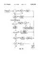
- FIG. 5shows a flow chart to the main loop of the program which controls the receiver module.
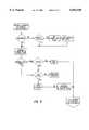
- FIGS. 6a and 6bshows a flow chart to the portion of the receiver program which processes NEW RF DATA from the wireless sensors.
- FIGS. 7a and 7bshow a flow chart to the portion of the receiver program which processes BUS MESSAGES.
- FIG. 8shows a flow chart to the operation of the processor at the receiver module which processes CURRENT OR CHANGED STATUS REQUESTS.
- the network 2includes a number of system controllers SC1 through SCn.
- Each system controller SC1 to SCnmonitors a distinct subscriber and communicates the condition of the monitored premises of each subscriber to a central station 4 via phone lines PL1 to PLn.
- Operating personnel at the central station 4monitor the data from each system controller and take appropriate action, depending upon the data received. Such action may comprise dispatching central station personnel, notifying appropriate local police and fire authorities via a phone line PLP, or notifying personnel at the secured premises.
- system controllers SC1 to SCncan be organized to communicate with one or more of the other system controllers, that is, a "buddy" system via an RF transmitter 6, for example, if the controller's system phone line is inoperative and provided the buddy system controller is mounted within range of the transmitter 6.
- the transmitter 6may alternatively comprise an independent wireless communication link to the central station 4.
- an audio alarm verification capabilitycan be added to each of the system controllers SC1 to SCn via an audio controller 8, such as shown at the system controller 10.
- the audio controller 8is hardwired to the system controller 10 at external (I/O) terminals. If the system controller 10 is supplied from Interactive Technologies, Inc., the phone line PL1 is coupled direct to the audio controller 8. Alternatively and as depicted in dashed line, the phone line PL1 can be coupled to the system controller 10. Separate phone lines may also be coupled to each of the audio and system controllers 8 and 10.
- the audio controller 8permits the central station 4 to audibly check the secured premises via distributed microphones for false alarms and to communicate with the premises via a local speaker 7. A solid state recording of audio activity at the monitored premises is also maintained to corroborate detected alarms.
- a plurality of alarm sensorscommunicate with the system controller 10.
- the sensors S1 and S2are coupled to the system controller 10 via hardwired conductor paths 12 and 14.
- a number of wireless sensor transmitters S3 to Snwhich can each be coupled to multiple switch contacts, communicate over radio frequency (RF) communication links with a supervised receiver module 9, see also FIG. 2.
- the receiver module 9is hardwired to the system controller 10 to either augment wireless capabilities of the system controller 10 or provide such capabilities to a controller 10 which previously responded only to hardwired sensors.
- the numbers of available hardwired and wireless sensors within any systemwill depend upon the capabilities of the supervised receiver module 9 and system controller 10.
- the capabilities of the receiver module 9might be integrated into a system controller 10. It is also to be appreciated, the receiver module 9 might be constructed to also respond to hardwired sensors, although it presently responds only to wireless sensors.
- the sensors S1 to Snmonitor a variety of physical conditions or events at a monitored premises, such as switch actuations (e.g. window, door, or floor mat), motion, temperature, smoke, water, etc..
- a hardwired keypad 16permits a remote programming of the system controller 10 and the receiver module 9.
- a wireless keypad 17might also be used to a similar end.
- the keypad 16can be responsive to transmissions from both the system controller 10 and supervised receiver module 9 and may include visual displays which convey appropriate messages to the system user.
- Each sensor S1 to Snis uniquely identified to the system controller 10.
- the wireless sensors S3 to Snare separately identified to the receiver module 9.
- the sensors S1 to Snmay be mapped to the system controller 10 in a geographically zoned configuration; that is, in relation to the physical geography of the premises being monitored. A variety of other physical reporting assignments are also possible.
- the re-transmission of alarm status and system data by the system controller 10 to the central station 4may be prioritized in relation to the criticality of the data. More of the details of the system controller 10, the sensors useable therewith, the central station 4 and possible system configurations and applications are available from pertinent product literature to the system components.
- Communications between the system controller 10 and receiver module 9occur over a three wire bus 11 (i.e. data and ground and positive voltage conductors).
- the communicationsare initiated by the system controller 10 with a status request, reference Table I.
- the receiver module 9responds with a status reply message, reference Tables II-IV, and wherein the term point is used interchangeably to identify a single sensor. That is, point or "pt" 1 is sensor 1.
- the status of each pointis conveyed with two bits of data.
- the possible states and interpretations corresponding to the point datais shown at Table V below.
- the status replycan either be an eight byte message or an extended thirteen byte message, reference FIGS. 3 and 4.
- each messageincludes address, length and command information, followed by sensor information (i.e. D1 to D4), status information (i.e. D5 to D9) and error checking information.
- Data bytes D5-D9provide information to the status of the receiver module 9 and the condition of the tamper switch, battery and the operating condition of the sensor transmitter circuitry.
- the D5-D9 dataare optional status information bytes for exception reporting and are sent as a group. For example, if D5 is present, D6-D9 will also be sent, even if the values are 0.
- the possible polling commands from the system controllersare shown at Table I.
- the possible sensor datais shown at Table V.
- Bit number 2 of data byte D9particularly indicates whether the receiver module 9 has received sensor data of any kind within a computed first period of time and from which the operational status of the receiver module 9 can be inferred.
- the receiver module 9transmits a logic high (1) condition at bit 2, which identifies a receiver failed status to the system controller 10.
- the supervised receiver periodis established at a minimum time period of two hours and fractional values are rounded up to the next whole number.
- the receiver supervisory periodis set to provide a sufficient number of transmissions to reasonably distinguish receiver failure from sensor transmitter failures.
- Sensor transmissionsoccur with the detection of alarm or event conditions.
- Supervisory transmissionsare also sent from each sensor transmitter S3 to Sn approximately once every hour or during a second period (e.g. every 60 to 64 minutes) over a 12 hour period.
- the supervisory transmissionsidentify the operating condition of the sensor transmitters and are also used to determine the proper operation of the receiver module 9. More of the details to the latter function are discussed below.
- bit 2 of D9needs to be set is made by the microprocessor 34.
- a receiver supervisory timeris maintained, separate from a number of sensor supervisory timers, and reset each time any RF sensor transmission is received by the microprocessor 34. Although shown as discrete timers, the sensor and receiver supervisory timers are maintained in the microprocessor 34. If no RF sensor transmissions are received within the receiver supervisory time period, bit 2 is set and transmitted to the system controller 10. With the next status transmission to the central station 4, the receiver failed status is transmitted to the central station 4 for analysis.
- the receiver failure informationmight induce central station personnel to transmit a message to another location, such as an off site guard service to check the system and receiver module 9, or possibly to converse with personnel at the site via the audio controller 8, if present in the system.
- a tamper switch 23is mounted in conventional fashion to the cover at the cabinet 21.
- the analog circuitry 18includes radio frequency (RF) receiver circuitry 20 which receives RF transmissions from each wireless sensor transmitter S3 to Sn via a pair of antennas 22.
- the receiver circuitry 20adjusts a noise floor level relative to ambient noise to detect a series of edges or interrupts which define the data being transmitted to the microprocessor 34.
- Analog to digital conversion circuitry 24converts the RF signals, during a data acquisition routine, into digital signals which are processed and stored in a table in random access memory (RAM) 26.
- RAM memory 26is updated as data is either received or not received from the sensor transmitters S3 to Sn.
- the tableincludes an addressable listing to the identity of each sensor, event status (i.e. normal, alarm or missing) and receiver tamper.
- event statusi.e. normal, alarm or missing
- receiver tamperFour status bits define the state of each sensor and two internal flags indicate a state change since the last data request.
- One flag bitdenotes changes in the sensor status and the other denotes changes in the tamper switches and battery conditions at the sensor transmitters.
- Level conversion circuitry 28boosts the logic voltage levels from 5 to 12 volts, prior to coupling the sensor and receiver module data to the bus 11 and the system controller 10.
- the system controller 10in turn, communicates via DTMF circuitry and the phone line PL1 with the central station 4 or with the keypads.
- Noise monitoring circuitry 36can be separately coupled to the receiver circuitry 20 to monitor the level or presence of noise as transmissions are received.
- the circuitry 36can contain a timer to measure the duration of noiseless interrupts on the data line of the receiver circuitry 20.
- the lack of noise for a periode.g. during the receiver supervisory period or possibly a shorter period such as one hour
- the lack of noisemight be transmitted as a separate flag with the receiver failure flag, if the supervisory receiver time period has timed out.
- the duration of the supervisory receiver periodmight be shortened, such to half of that determined at Table VI, when the noise monitoring circuitry 36 doesn't detect noise. In the latter instance, it is contemplated a minimum period would still apply for the supervisory receiver period to assure a sufficient sampling of transmissions.
- a non-volatile, E 2 PROM memory 40which stores the identification numbers of the sensors coupled to the receiver module 9.
- the sensor identification numbers of the receiver module 9can either be manually programmed or learned as each wireless sensor S3-Sn reports to the receiver module 9. Should a system power failure occur, the data at the E 2 PROM memory is used to reload the RAM memory 26 with the appropriate sensor ID numbers for the system.
- the operations of the receiver module 9are controlled by the microprocessor 34. Microcoded operating instructions are stored in associated memory.
- the flow charts of FIGS. 5 through 8 and the source code listing at Appendix Afurther describe the operations performed to identify whether the receiver module 9 has failed.
- the microprocessor 34 in a slave capacityresponds to the data requests from the system controller 10 over the bus 11.
- a separate microprocessor within the system controller 10controls the primary operation of the system.
- the transmissionsare converted into digital signals for processing.
- the signalsare converted by measuring the time separation between RF pulses that comprise each transmission.
- the time between pulsesindicates whether a logic high (1) or a low (0) is received.
- a counteris reset, the time values are calculated and the data bits are saved at a data collection shift register 40.
- the shift register 40is included at the microprocessor 34. This continues until a predetermined number of data bits constituting a valid message are collected at the shift register 40.
- the microprocessor 34is notified by setting a NEW DATA RF flag, reference FIG. 5.
- the Main Loop of the receiver module programinitiates a PROCESS NEW RF DATA routine, reference FIGS. 6a and 6b, wherein current status (CSTAT) and shuttle segments of RAM 26 are updated and the NEW BUS DATA flag may be set.
- the programperforms a PROCESS BUS MESSAGE routine, reference FIGS. 7a and 7b.
- each transmissionis verified as coming from a valid sensor by comparing the identification data in the message to the sensor ID values stored in RAM 26. If a valid sensor is detected, the sensor's status is updated at RAM 26 to the current status and the time when the transmission was received. If neither an alarm or event message nor supervisory message is received within each sensor's supervisory period, the sensor status condition is set to a missing condition (00), reference Table V.
- a supervisory messageis structured the same as an event driven transmission and includes sensor specific identification data, sensor tamper data and low battery data. Also included are at least one preamble or start bit and at least one error checking bit. Each supervisory transmission is transmitted in triplicate as a message packet for redundancy. The period of a sensor supervisory timer is reset after any transmission from each sensor transmitter S3 to Sn.
- the receiver module 9expects at least one supervisory transmission from each sensor transmitter once approximately every hour. If no transmissions are received, a problem can exist at either the receiver module or the sensor transmitters. With multiple sensors in the system, the problem may be narrowed to a particular sensor, if messages are being received from other sensors. If, however, no messages are being received, the system controller 10 does not know whether all sensors or the receiver module 9 has failed.
- receiver module 9Problems with the receiver module 9 might be loss of power to the microprocessor 34 or a broken connection between the analog and digital sections 18 and 19. Also, even if the analog circuitry 18 stops working, communications between the receiver module 9 and system controller 10 will continue and the system controller 10 will receive MISSING SENSOR X messages, even though the sensors are operating properly. The availability of the receiver failure flag therefore provides the system controller 10 with an early warning to the potential failure of the receiver module 9.
- the receiver failure or supervisory functionis implemented in the receiver module 9 with a separate 24/# Sn or receiver supervisory timer at the microprocessor 34 which monitors the occurrence of sensor transmissions relative to the timer. If neither event nor supervisory transmissions are received from any sensor transmitters S3 to Sn within a certain time determined in relation to the number of sensors coupled to the system, the receiver failure flag is reported.
- Receiver failure and missing sensor status updatesare performed during a one MSEC TIMER INTERRUPT routine via an interrupt timer. If no sensor transmissions are received when the timer reaches one hour, supervisory time period values stored in RAM 26 and assigned to the receiver module and to each of the sensor transmitters S3 through Sn are decremented. The supervisory or failure period for the receiver module 9 is determined in relation to Table VI. When either or both the time values for the receiver module 9 or the sensor transmitters S3 to Sn have been decremented to zero, the appropriate RECEIVER FAILURE and MISSING SENSOR X status flags are set in a current status memory area (CSTAT) in RAM 26. The SHUTTLE memory area in RAM 26 is also updated.
- STATcurrent status memory area
- the transmitting sensor's supervisory time valueis reset to its start value during the Process New RF Data routine.
- the supervisory time value of the receiver module 9is also reset to its start value, reference FIGS. 6a and 6b and Appendix A.
- the current status CSTAT memory areais separately updated with the new sensor and receiver status information.
- the shuttle memoryis used to separately form a status reply message and is updated only if the new sensor information contains a higher priority alarm than previously loaded.
- a NEW BUS DATA flagis set which causes the microprocessor 34 to enter the PROCESS BUS MESSAGE routine, FIGS. 7a and 7b.
- the microprocessor 34reads the polled message, clears a LRN DATA RCVD Flag and sets the MODE to NORMAL.
- the microprocessor 34then branches to the PROCESS CURRENT OR CHANGED STATUS REQUEST routine, reference FIG. 8, to select and couple the proper data to the system controller 10.
- the microprocessor 34configures the status reply message. It first determines whether a CHANGE-UP flag was set in the PROCESS NEW RF DATA routine. If no CHANGE-UP flag was set, the CSTAT data is compared to the data stored in the shuttle memory. If they are unequal, a CHANGE-DOWN flag is set and the CSTAT data is copied into the shuttle memory.
- the programlooks to see if the controller 10 is asking whether a status change occurred. If it is and no changes have occurred, the status request is simply acknowledged. If changes have occurred or if the controller 10 is asking for other than changes, the program branches to determine whether a short or extended message should be transmitted. If either a sensor tamper and/or battery change flag or a receiver module failure flag has been set, the extended thirteen byte reply is sent. Otherwise, the eight byte reply is sent and the PROCESS CURRENT OR CHANGED STATUS REQUEST routine is exited back to the Main Loop, after clearing the change-up and change-down flags.
- the system controller 10upon receiving notice to the condition normally notifies personnel to physically check the receiver module 9. An early warning is thereby obtained in advance of waiting until MISSING SENSOR X data is received from all the sensors S3 to Sn.
Landscapes
- Engineering & Computer Science (AREA)
- Physics & Mathematics (AREA)
- General Physics & Mathematics (AREA)
- Computer Security & Cryptography (AREA)
- Computer Networks & Wireless Communication (AREA)
- Business, Economics & Management (AREA)
- Emergency Management (AREA)
- Alarm Systems (AREA)
- Selective Calling Equipment (AREA)
Abstract
Description
TABLE I ______________________________________ SYSTEM CONTROLLER POLL CONMANDS CMD # Panel Command Reply Rcr. Response ______________________________________ 00 Reset 07 RF point status 03 Current sensor status 07 RF point status extd 04 Latch sensor status 07 RF point status extd 15 Changed sensor status -- none (if no change) RF point status 07 RF point status extd07 22 Write RF pararneters 23 Write RF ack 24 Rq RF pararneters 25 RF parameters reply 26 Learn RF sensor Learn RF sensor rply Dup.RF sensor reply 28 29 Exit RF learn rnode 2A Rqst RF test rnode 2B RF test reply 2C Exit RF test rnode -- none 2D Remove RF sensor -- none ______________________________________
TABLE II ______________________________________ RF POINT STATUS REPLY BYTE # NAME b7 b6 b5 b4 b3 b2 b1 b0 DESCRP ______________________________________ addraddress 2 len = 6byte count 3 cmd = 07cmnd # 4 D1 pt pt pt pt pt pt ptpt sensor sts 1 1 2 2 3 3 4 4 5 D2 pt pt pt pt pt pt pt pt sensor sts 5 5 6 6 7 7 8 8 6 D3 pt pt pt pt pt pt ptpt sensor sts 9 9 10 10 11 11 12 12 7 D4 pt pt pt pt pt pt pt pt sensor sts 133 14 14 15 15 16 16 8 chk sum ______________________________________ 1-7
TABLE III ______________________________________ RF POINT STATUS REPLY EXTENDED BYTE # NAME b7 b6 b5 b4 b3 b2 b1 b0 DESCRP ______________________________________ addraddress 2 len = 11byte count 3 cmd = 07cmnd # 4D1 1t pt 2pt 3pt 4 sensor sts 5D2 5t pt 6 pt 7pt 8sensor sts 6D3 pt 9pt 10pt 11pt 12 sensor sts 7 D3 pt 13pt 14 pt 15pt 16sensor sts 8 D5 pt pt pt ptpt pt pt 1 = tamper 7 6 8 5 4 3 2 1 9 D6 pt pt pt ptpt pt pt 1 = tamper 15 14 16 13 12 11 10 9 10 D7 pt pt pt ptpt pt pt 1 = lo bty 7 6 8 5 4 3 2 1 11 D8 pt pt pt ptpt pt pt 1 = lo bty 15 14 16 13 12 11 10 9 12 D9 (Reference Table IV) rcr sts** 13 chk sum ofbytes 1 & ______________________________________ 2
TABLE IV ______________________________________ RF RECEIVER STATUS ______________________________________ b7 b6 b5 b4 b3 b2b1 b0 b0 1 =Receiver tamper b1 1 = reset, no sensors programmedb2 1 = Receiver fail (No sensor data received within supvsd time) b3 LSBit of Receiver module versionnumber b4 Bit 2 of Receiver module version number b5 MSBit of Receiver module version number b6 Unused (set = 0) b7 Unused (set = 0) ______________________________________
TABLE V ______________________________________ SENSOR STATUS BITS Sensor State Tamper Lo Bty Sensor Status ______________________________________ 00 x x Supervisory/Missing 01 xx Alarm Faulted 10 x x Trouble 11 x Normal xx x1 Sensor tamper xx 1x Sensor Low Battery ______________________________________
TABLE VI ______________________________________ RECEIVER SUPERVISORY PERIOD # OF SENSORS HOURS ______________________________________ 1 24 2 12 3 8 4 6 5 5 6 4 7 4 8 3 9 3 10 3 11 3 12 2 >12 2 ______________________________________
Claims (17)
Priority Applications (1)
| Application Number | Priority Date | Filing Date | Title |
|---|---|---|---|
| US08/730,709US6054920A (en) | 1996-10-15 | 1996-10-15 | Alarm system receiver supervisor |
Applications Claiming Priority (1)
| Application Number | Priority Date | Filing Date | Title |
|---|---|---|---|
| US08/730,709US6054920A (en) | 1996-10-15 | 1996-10-15 | Alarm system receiver supervisor |
Publications (1)
| Publication Number | Publication Date |
|---|---|
| US6054920Atrue US6054920A (en) | 2000-04-25 |
Family
ID=24936502
Family Applications (1)
| Application Number | Title | Priority Date | Filing Date |
|---|---|---|---|
| US08/730,709Expired - LifetimeUS6054920A (en) | 1996-10-15 | 1996-10-15 | Alarm system receiver supervisor |
Country Status (1)
| Country | Link |
|---|---|
| US (1) | US6054920A (en) |
Cited By (39)
| Publication number | Priority date | Publication date | Assignee | Title |
|---|---|---|---|---|
| US6353385B1 (en)* | 2000-08-25 | 2002-03-05 | Hyperon Incorporated | Method and system for interfacing an intrusion detection system to a central alarm system |
| US20020027504A1 (en)* | 1999-03-18 | 2002-03-07 | James Davis | System and method for controlling communication between a host computer and communication devices associated with remote devices in an automated monitoring system |
| US6366211B1 (en)* | 2000-05-15 | 2002-04-02 | Digital Security Controls Ltd. | Remote recovery arrangement for alarm system |
| US20020076060A1 (en)* | 2000-12-19 | 2002-06-20 | Hall Ronald W. | Programmable headset and programming apparatus and method |
| US20030134666A1 (en)* | 2002-01-15 | 2003-07-17 | Fletcher Douglas D. | Wireless intercom system |
| US20040116071A1 (en)* | 2002-12-16 | 2004-06-17 | 3M Innovative Properties Company | Wireless intercom system and method of communicating using wireless intercom system |
| US20040149939A1 (en)* | 2001-06-04 | 2004-08-05 | Adam Matthew Dickson | Monitoring process and system |
| US20040177121A1 (en)* | 2003-03-07 | 2004-09-09 | Wegener Communications, Inc. | System and method for command transmission utilizing an email return path |
| US6850157B1 (en)* | 2000-06-22 | 2005-02-01 | Matsushita Electric Industrial Co., Ltd. | Wireless data acquisition system |
| US6993292B2 (en) | 2002-02-26 | 2006-01-31 | 3M Innovative Properties Company | Self-monitoring radio network |
| US20060082464A1 (en)* | 2004-10-18 | 2006-04-20 | Walter Kidde Portable Equipment, Inc. | Low battery warning silencing in life safety devices |
| US20060082461A1 (en)* | 2004-10-18 | 2006-04-20 | Walter Kidde Portable Equipment, Inc. | Gateway device to interconnect system including life safety devices |
| US20060082455A1 (en)* | 2004-10-18 | 2006-04-20 | Walter Kidde Portable Equipment, Inc. | Radio frequency communications scheme in life safety devices |
| US7079810B2 (en) | 1997-02-14 | 2006-07-18 | Statsignal Ipc, Llc | System and method for communicating with a remote communication unit via the public switched telephone network (PSTN) |
| US7103511B2 (en) | 1998-10-14 | 2006-09-05 | Statsignal Ipc, Llc | Wireless communication networks for providing remote monitoring of devices |
| US7137550B1 (en) | 1997-02-14 | 2006-11-21 | Statsignal Ipc, Llc | Transmitter for accessing automated financial transaction machines |
| US7263073B2 (en) | 1999-03-18 | 2007-08-28 | Statsignal Ipc, Llc | Systems and methods for enabling a mobile user to notify an automated monitoring system of an emergency situation |
| US7295128B2 (en) | 1998-06-22 | 2007-11-13 | Sipco, Llc | Smoke detection methods, devices, and systems |
| US20080070547A1 (en)* | 2006-09-18 | 2008-03-20 | Siemens Building Technologies Fire & Security Products Gmbh & Co.Ohg | Method for Radio Transmission in a Radio Cell of an Alarm System |
| US7397907B2 (en) | 1997-02-14 | 2008-07-08 | Sipco, Llc | Multi-function general purpose transceiver |
| US7424527B2 (en) | 2001-10-30 | 2008-09-09 | Sipco, Llc | System and method for transmitting pollution information over an integrated wireless network |
| US7480501B2 (en) | 2001-10-24 | 2009-01-20 | Statsignal Ipc, Llc | System and method for transmitting an emergency message over an integrated wireless network |
| US20090201145A1 (en)* | 2008-02-06 | 2009-08-13 | Hector Mario Vasquez | Safety socket |
| US7697492B2 (en) | 1998-06-22 | 2010-04-13 | Sipco, Llc | Systems and methods for monitoring and controlling remote devices |
| US7756086B2 (en) | 2004-03-03 | 2010-07-13 | Sipco, Llc | Method for communicating in dual-modes |
| USRE41919E1 (en) | 2003-06-25 | 2010-11-09 | Steve Olivier | Rapid decryption of data by key synchronization and indexing |
| US20110102128A1 (en)* | 2009-10-30 | 2011-05-05 | Hon Hai Precision Industry Co., Ltd. | Monitoring system and input/output device thereof |
| US8000314B2 (en) | 1996-12-06 | 2011-08-16 | Ipco, Llc | Wireless network system and method for providing same |
| US8013732B2 (en) | 1998-06-22 | 2011-09-06 | Sipco, Llc | Systems and methods for monitoring and controlling remote devices |
| US8031650B2 (en) | 2004-03-03 | 2011-10-04 | Sipco, Llc | System and method for monitoring remote devices with a dual-mode wireless communication protocol |
| US8064412B2 (en) | 1998-06-22 | 2011-11-22 | Sipco, Llc | Systems and methods for monitoring conditions |
| US8410931B2 (en) | 1998-06-22 | 2013-04-02 | Sipco, Llc | Mobile inventory unit monitoring systems and methods |
| US8489063B2 (en) | 2001-10-24 | 2013-07-16 | Sipco, Llc | Systems and methods for providing emergency messages to a mobile device |
| US8787246B2 (en) | 2009-02-03 | 2014-07-22 | Ipco, Llc | Systems and methods for facilitating wireless network communication, satellite-based wireless network systems, and aircraft-based wireless network systems, and related methods |
| US9129501B1 (en)* | 2014-09-14 | 2015-09-08 | Voalte, Inc. | Augmented acknowledgement of alarms and messages in mobile health systems |
| US9439126B2 (en) | 2005-01-25 | 2016-09-06 | Sipco, Llc | Wireless network protocol system and methods |
| US20170230168A1 (en)* | 2007-08-14 | 2017-08-10 | Infineon Technologies Ag | Sensor that transmits signals responsive to a request signal and receives information |
| US10699540B2 (en)* | 2018-10-11 | 2020-06-30 | Sercomm Corporation | Electronic device that can detect and report tampering |
| CN114326719A (en)* | 2021-12-20 | 2022-04-12 | 苏州光格科技股份有限公司 | Inspection robot control method, system, computer equipment and storage medium |
Citations (2)
| Publication number | Priority date | Publication date | Assignee | Title |
|---|---|---|---|---|
| US4772876A (en)* | 1986-10-10 | 1988-09-20 | Zenith Electronics Corporation | Remote security transmitter address programmer |
| US4988989A (en)* | 1987-10-26 | 1991-01-29 | Sharp Kabushiki Kaisha | Master-slave communication system for stations having timer means |
- 1996
- 1996-10-15USUS08/730,709patent/US6054920A/ennot_activeExpired - Lifetime
Patent Citations (2)
| Publication number | Priority date | Publication date | Assignee | Title |
|---|---|---|---|---|
| US4772876A (en)* | 1986-10-10 | 1988-09-20 | Zenith Electronics Corporation | Remote security transmitter address programmer |
| US4988989A (en)* | 1987-10-26 | 1991-01-29 | Sharp Kabushiki Kaisha | Master-slave communication system for stations having timer means |
Cited By (77)
| Publication number | Priority date | Publication date | Assignee | Title |
|---|---|---|---|---|
| US8982856B2 (en) | 1996-12-06 | 2015-03-17 | Ipco, Llc | Systems and methods for facilitating wireless network communication, satellite-based wireless network systems, and aircraft-based wireless network systems, and related methods |
| US8625496B2 (en) | 1996-12-06 | 2014-01-07 | Ipco, Llc | Wireless network system and method for providing same |
| US8233471B2 (en) | 1996-12-06 | 2012-07-31 | Ipco, Llc | Wireless network system and method for providing same |
| US8000314B2 (en) | 1996-12-06 | 2011-08-16 | Ipco, Llc | Wireless network system and method for providing same |
| US7079810B2 (en) | 1997-02-14 | 2006-07-18 | Statsignal Ipc, Llc | System and method for communicating with a remote communication unit via the public switched telephone network (PSTN) |
| US7397907B2 (en) | 1997-02-14 | 2008-07-08 | Sipco, Llc | Multi-function general purpose transceiver |
| US7137550B1 (en) | 1997-02-14 | 2006-11-21 | Statsignal Ipc, Llc | Transmitter for accessing automated financial transaction machines |
| US8964708B2 (en) | 1998-06-22 | 2015-02-24 | Sipco Llc | Systems and methods for monitoring and controlling remote devices |
| US8212667B2 (en) | 1998-06-22 | 2012-07-03 | Sipco, Llc | Automotive diagnostic data monitoring systems and methods |
| US8013732B2 (en) | 1998-06-22 | 2011-09-06 | Sipco, Llc | Systems and methods for monitoring and controlling remote devices |
| US8410931B2 (en) | 1998-06-22 | 2013-04-02 | Sipco, Llc | Mobile inventory unit monitoring systems and methods |
| US9691263B2 (en) | 1998-06-22 | 2017-06-27 | Sipco, Llc | Systems and methods for monitoring conditions |
| US7697492B2 (en) | 1998-06-22 | 2010-04-13 | Sipco, Llc | Systems and methods for monitoring and controlling remote devices |
| US9571582B2 (en) | 1998-06-22 | 2017-02-14 | Sipco, Llc | Systems and methods for monitoring and controlling remote devices |
| US9430936B2 (en) | 1998-06-22 | 2016-08-30 | Sipco Llc | Systems and methods for monitoring and controlling remote devices |
| US8064412B2 (en) | 1998-06-22 | 2011-11-22 | Sipco, Llc | Systems and methods for monitoring conditions |
| US8223010B2 (en) | 1998-06-22 | 2012-07-17 | Sipco Llc | Systems and methods for monitoring vehicle parking |
| US9129497B2 (en) | 1998-06-22 | 2015-09-08 | Statsignal Systems, Inc. | Systems and methods for monitoring conditions |
| US7295128B2 (en) | 1998-06-22 | 2007-11-13 | Sipco, Llc | Smoke detection methods, devices, and systems |
| US7103511B2 (en) | 1998-10-14 | 2006-09-05 | Statsignal Ipc, Llc | Wireless communication networks for providing remote monitoring of devices |
| US7263073B2 (en) | 1999-03-18 | 2007-08-28 | Statsignal Ipc, Llc | Systems and methods for enabling a mobile user to notify an automated monitoring system of an emergency situation |
| US20020027504A1 (en)* | 1999-03-18 | 2002-03-07 | James Davis | System and method for controlling communication between a host computer and communication devices associated with remote devices in an automated monitoring system |
| US7650425B2 (en)* | 1999-03-18 | 2010-01-19 | Sipco, Llc | System and method for controlling communication between a host computer and communication devices associated with remote devices in an automated monitoring system |
| US8930571B2 (en) | 1999-03-18 | 2015-01-06 | Sipco, LLP | Systems and methods for controlling communication between a host computer and communication devices |
| US8924587B2 (en) | 1999-03-18 | 2014-12-30 | Sipco, Llc | Systems and methods for controlling communication between a host computer and communication devices |
| US8924588B2 (en) | 1999-03-18 | 2014-12-30 | Sipco, Llc | Systems and methods for controlling communication between a host computer and communication devices |
| US6366211B1 (en)* | 2000-05-15 | 2002-04-02 | Digital Security Controls Ltd. | Remote recovery arrangement for alarm system |
| US6850157B1 (en)* | 2000-06-22 | 2005-02-01 | Matsushita Electric Industrial Co., Ltd. | Wireless data acquisition system |
| US6353385B1 (en)* | 2000-08-25 | 2002-03-05 | Hyperon Incorporated | Method and system for interfacing an intrusion detection system to a central alarm system |
| US20020076060A1 (en)* | 2000-12-19 | 2002-06-20 | Hall Ronald W. | Programmable headset and programming apparatus and method |
| US7522044B2 (en)* | 2001-06-04 | 2009-04-21 | Ceos Industrial Pty Ltd | Monitoring process and system |
| US20040149939A1 (en)* | 2001-06-04 | 2004-08-05 | Adam Matthew Dickson | Monitoring process and system |
| US8666357B2 (en) | 2001-10-24 | 2014-03-04 | Sipco, Llc | System and method for transmitting an emergency message over an integrated wireless network |
| US7480501B2 (en) | 2001-10-24 | 2009-01-20 | Statsignal Ipc, Llc | System and method for transmitting an emergency message over an integrated wireless network |
| US8489063B2 (en) | 2001-10-24 | 2013-07-16 | Sipco, Llc | Systems and methods for providing emergency messages to a mobile device |
| US9282029B2 (en) | 2001-10-24 | 2016-03-08 | Sipco, Llc. | System and method for transmitting an emergency message over an integrated wireless network |
| US9615226B2 (en) | 2001-10-24 | 2017-04-04 | Sipco, Llc | System and method for transmitting an emergency message over an integrated wireless network |
| US10149129B2 (en) | 2001-10-24 | 2018-12-04 | Sipco, Llc | Systems and methods for providing emergency messages to a mobile device |
| US10687194B2 (en) | 2001-10-24 | 2020-06-16 | Sipco, Llc | Systems and methods for providing emergency messages to a mobile device |
| US9111240B2 (en) | 2001-10-30 | 2015-08-18 | Sipco, Llc. | System and method for transmitting pollution information over an integrated wireless network |
| US8171136B2 (en) | 2001-10-30 | 2012-05-01 | Sipco, Llc | System and method for transmitting pollution information over an integrated wireless network |
| US9515691B2 (en) | 2001-10-30 | 2016-12-06 | Sipco, Llc. | System and method for transmitting pollution information over an integrated wireless network |
| US7424527B2 (en) | 2001-10-30 | 2008-09-09 | Sipco, Llc | System and method for transmitting pollution information over an integrated wireless network |
| US20030134666A1 (en)* | 2002-01-15 | 2003-07-17 | Fletcher Douglas D. | Wireless intercom system |
| US7103392B2 (en) | 2002-01-15 | 2006-09-05 | 3M Innovative Properties Company | Wireless intercom system |
| US7715799B2 (en) | 2002-02-26 | 2010-05-11 | 3M Innovative Properties Company | Self-monitoring radio network |
| US6993292B2 (en) | 2002-02-26 | 2006-01-31 | 3M Innovative Properties Company | Self-monitoring radio network |
| US20060030269A1 (en)* | 2002-02-26 | 2006-02-09 | 3M Innovative Properties Company | Self-monitoring radio network |
| US7120388B2 (en) | 2002-12-16 | 2006-10-10 | 3M Innovative Properties Company | Wireless intercom system and method of communicating using wireless intercom system |
| US20040116071A1 (en)* | 2002-12-16 | 2004-06-17 | 3M Innovative Properties Company | Wireless intercom system and method of communicating using wireless intercom system |
| US7020689B2 (en)* | 2003-03-07 | 2006-03-28 | Wegener Communications, Inc. | System and method for command transmission utilizing an email return path |
| US20040177121A1 (en)* | 2003-03-07 | 2004-09-09 | Wegener Communications, Inc. | System and method for command transmission utilizing an email return path |
| USRE41919E1 (en) | 2003-06-25 | 2010-11-09 | Steve Olivier | Rapid decryption of data by key synchronization and indexing |
| US7756086B2 (en) | 2004-03-03 | 2010-07-13 | Sipco, Llc | Method for communicating in dual-modes |
| US8031650B2 (en) | 2004-03-03 | 2011-10-04 | Sipco, Llc | System and method for monitoring remote devices with a dual-mode wireless communication protocol |
| US8379564B2 (en) | 2004-03-03 | 2013-02-19 | Sipco, Llc | System and method for monitoring remote devices with a dual-mode wireless communication protocol |
| US8446884B2 (en) | 2004-03-03 | 2013-05-21 | Sipco, Llc | Dual-mode communication devices, methods and systems |
| US7339468B2 (en) | 2004-10-18 | 2008-03-04 | Walter Kidde Portable Equipment, Inc. | Radio frequency communications scheme in life safety devices |
| US20060082461A1 (en)* | 2004-10-18 | 2006-04-20 | Walter Kidde Portable Equipment, Inc. | Gateway device to interconnect system including life safety devices |
| US7385517B2 (en) | 2004-10-18 | 2008-06-10 | Walter Kidde Portable Equipment, Inc. | Gateway device to interconnect system including life safety devices |
| US7508314B2 (en) | 2004-10-18 | 2009-03-24 | Walter Kidde Portable Equipment, Inc. | Low battery warning silencing in life safety devices |
| US20060082455A1 (en)* | 2004-10-18 | 2006-04-20 | Walter Kidde Portable Equipment, Inc. | Radio frequency communications scheme in life safety devices |
| US20060082464A1 (en)* | 2004-10-18 | 2006-04-20 | Walter Kidde Portable Equipment, Inc. | Low battery warning silencing in life safety devices |
| US10356687B2 (en) | 2005-01-25 | 2019-07-16 | Sipco, Llc | Wireless network protocol systems and methods |
| US9439126B2 (en) | 2005-01-25 | 2016-09-06 | Sipco, Llc | Wireless network protocol system and methods |
| US9860820B2 (en) | 2005-01-25 | 2018-01-02 | Sipco, Llc | Wireless network protocol systems and methods |
| US11039371B2 (en) | 2005-01-25 | 2021-06-15 | Sipco, Llc | Wireless network protocol systems and methods |
| US20080070547A1 (en)* | 2006-09-18 | 2008-03-20 | Siemens Building Technologies Fire & Security Products Gmbh & Co.Ohg | Method for Radio Transmission in a Radio Cell of an Alarm System |
| US20170230168A1 (en)* | 2007-08-14 | 2017-08-10 | Infineon Technologies Ag | Sensor that transmits signals responsive to a request signal and receives information |
| US10700848B2 (en)* | 2007-08-14 | 2020-06-30 | Infineon Technologies Ag | Sensor that transmits signals responsive to a request signal and receives information |
| US20090201145A1 (en)* | 2008-02-06 | 2009-08-13 | Hector Mario Vasquez | Safety socket |
| US8787246B2 (en) | 2009-02-03 | 2014-07-22 | Ipco, Llc | Systems and methods for facilitating wireless network communication, satellite-based wireless network systems, and aircraft-based wireless network systems, and related methods |
| US8289128B2 (en)* | 2009-10-30 | 2012-10-16 | Hon Hai Precision Industry Co., Ltd. | Monitoring system and input/output device thereof |
| US20110102128A1 (en)* | 2009-10-30 | 2011-05-05 | Hon Hai Precision Industry Co., Ltd. | Monitoring system and input/output device thereof |
| US9129501B1 (en)* | 2014-09-14 | 2015-09-08 | Voalte, Inc. | Augmented acknowledgement of alarms and messages in mobile health systems |
| US10699540B2 (en)* | 2018-10-11 | 2020-06-30 | Sercomm Corporation | Electronic device that can detect and report tampering |
| CN114326719A (en)* | 2021-12-20 | 2022-04-12 | 苏州光格科技股份有限公司 | Inspection robot control method, system, computer equipment and storage medium |
Similar Documents
| Publication | Publication Date | Title |
|---|---|---|
| US6054920A (en) | Alarm system receiver supervisor | |
| US4951029A (en) | Micro-programmable security system | |
| US5485142A (en) | Remote monitor alarm system | |
| US5039980A (en) | Multi-nodal communication network with coordinated responsibility for global functions by the nodes | |
| AU611913B2 (en) | Supervised, interactive alarm reporting system | |
| US5128979A (en) | Monitored personal emergency response system | |
| US5416725A (en) | Computer-based notification system having redundant sensor alarm determination and associated computer-implemented method for issuing notification of events | |
| US5027383A (en) | Supervised, interactive alarm reporting system | |
| CA1306501C (en) | Monitoring system for radio communication apparatus | |
| US6690276B1 (en) | Method and apparatus for monitoring message acknowledgements in a security system | |
| JPH07170583A (en) | System for acquisiting and communicating remote data | |
| US20040075550A1 (en) | Method and apparatus for determining message response type in a security system | |
| US4339746A (en) | Alarm control center | |
| US4527235A (en) | Subscriber terminal polling unit | |
| US5576689A (en) | Self testing personal response system with programmable timer values | |
| US20040066935A1 (en) | Method and apparatus for providing a message sequence count in a security system | |
| US20040075551A1 (en) | Method and apparatus for filtering non-essential messages in a disarmed security system | |
| US7617331B2 (en) | System and method of double address detection | |
| US6577233B2 (en) | Fire alarm system and terminal equipment in the same | |
| US5786757A (en) | Load shed scheme for two wire data transmission | |
| EP0084685A1 (en) | Alarm control center | |
| EP0402129A2 (en) | Location identification system | |
| WO1997026635A1 (en) | A networked, distributed fire alarm system | |
| JP2858266B2 (en) | Fire alarm system with alarm level switching function | |
| GB2313458A (en) | Supervised alarm reporting system |
Legal Events
| Date | Code | Title | Description |
|---|---|---|---|
| AS | Assignment | Owner name:INTERACTIVE TECHNOLOGIES, INC., MINNESOTA Free format text:ASSIGNMENT OF ASSIGNORS INTEREST;ASSIGNORS:SMITH, DAVID M.;HENDRICKSON, ROB;REEL/FRAME:008275/0123 Effective date:19961014 | |
| STCF | Information on status: patent grant | Free format text:PATENTED CASE | |
| FEPP | Fee payment procedure | Free format text:PAT HOLDER NO LONGER CLAIMS SMALL ENTITY STATUS, ENTITY STATUS SET TO UNDISCOUNTED (ORIGINAL EVENT CODE: STOL); ENTITY STATUS OF PATENT OWNER: LARGE ENTITY | |
| REFU | Refund | Free format text:REFUND - SURCHARGE, PETITION TO ACCEPT PYMT AFTER EXP, UNINTENTIONAL (ORIGINAL EVENT CODE: R2551); ENTITY STATUS OF PATENT OWNER: LARGE ENTITY | |
| FPAY | Fee payment | Year of fee payment:4 | |
| AS | Assignment | Owner name:GE INTERLOGIX, INC., FLORIDA Free format text:ASSIGNMENT OF ASSIGNORS INTEREST;ASSIGNOR:INTERACTIVE TECHNOLOGIES, INC.;REEL/FRAME:017073/0440 Effective date:20021231 | |
| FPAY | Fee payment | Year of fee payment:8 | |
| REMI | Maintenance fee reminder mailed | ||
| AS | Assignment | Owner name:GE SECURITY, INC., TEXAS Free format text:CHANGE OF NAME;ASSIGNOR:GE INTERLOGIX, INC.;REEL/FRAME:022960/0020 Effective date:20040120 | |
| FPAY | Fee payment | Year of fee payment:12 | |
| AS | Assignment | Owner name:UTC FIRE & SECURITY AMERICAS CORPORATION, INC., NO Free format text:CHANGE OF NAME;ASSIGNOR:GE SECURITY, INC.;REEL/FRAME:044530/0811 Effective date:20100401 |