US6054676A - Method and apparatus for cooling an integrated circuit device - Google Patents
Method and apparatus for cooling an integrated circuit deviceDownload PDFInfo
- Publication number
- US6054676A US6054676AUS09/020,766US2076698AUS6054676AUS 6054676 AUS6054676 AUS 6054676AUS 2076698 AUS2076698 AUS 2076698AUS 6054676 AUS6054676 AUS 6054676A
- Authority
- US
- United States
- Prior art keywords
- socket
- integrated circuit
- heater board
- cooling
- circuit device
- Prior art date
- Legal status (The legal status is an assumption and is not a legal conclusion. Google has not performed a legal analysis and makes no representation as to the accuracy of the status listed.)
- Expired - Fee Related
Links
- 238000001816coolingMethods0.000titleclaimsabstractdescription65
- 238000000034methodMethods0.000titledescription15
- 238000010438heat treatmentMethods0.000claimsabstractdescription50
- 238000009833condensationMethods0.000claimsabstractdescription25
- 230000005494condensationEffects0.000claimsabstractdescription25
- 229920000642polymerPolymers0.000claimsabstractdescription8
- 229910052751metalInorganic materials0.000claimsdescription11
- 239000002184metalSubstances0.000claimsdescription11
- 238000012544monitoring processMethods0.000claimsdescription8
- 230000008878couplingEffects0.000claimsdescription6
- 238000010168coupling processMethods0.000claimsdescription6
- 238000005859coupling reactionMethods0.000claimsdescription6
- 238000007789sealingMethods0.000claimsdescription6
- 229910000679solderInorganic materials0.000claimsdescription6
- 239000004593EpoxySubstances0.000claimsdescription4
- 239000012080ambient airSubstances0.000claimsdescription4
- 238000013508migrationMethods0.000claimsdescription3
- 230000005012migrationEffects0.000claimsdescription3
- 230000003213activating effectEffects0.000claims1
- 239000002826coolantSubstances0.000description16
- 239000012212insulatorSubstances0.000description12
- 239000000463materialSubstances0.000description7
- 235000020004porterNutrition0.000description7
- 238000002955isolationMethods0.000description4
- 239000000243solutionSubstances0.000description4
- WYTGDNHDOZPMIW-RCBQFDQVSA-NalstonineNatural productsC1=CC2=C3C=CC=CC3=NC2=C2N1C[C@H]1[C@H](C)OC=C(C(=O)OC)[C@H]1C2WYTGDNHDOZPMIW-RCBQFDQVSA-N0.000description3
- 230000008901benefitEffects0.000description3
- 239000004020conductorSubstances0.000description3
- 239000006260foamSubstances0.000description3
- 238000009413insulationMethods0.000description3
- 239000007788liquidSubstances0.000description3
- IJGRMHOSHXDMSA-UHFFFAOYSA-NAtomic nitrogenChemical compoundN#NIJGRMHOSHXDMSA-UHFFFAOYSA-N0.000description2
- 238000010586diagramMethods0.000description2
- 238000005530etchingMethods0.000description2
- 238000009434installationMethods0.000description2
- 238000012986modificationMethods0.000description2
- 230000004048modificationEffects0.000description2
- 230000008569processEffects0.000description2
- 238000012545processingMethods0.000description2
- 239000003507refrigerantSubstances0.000description2
- 239000004065semiconductorSubstances0.000description2
- RYGMFSIKBFXOCR-UHFFFAOYSA-NCopperChemical compound[Cu]RYGMFSIKBFXOCR-UHFFFAOYSA-N0.000description1
- 241000270295SerpentesSpecies0.000description1
- 238000007792additionMethods0.000description1
- 239000000853adhesiveSubstances0.000description1
- 230000001070adhesive effectEffects0.000description1
- 239000003570airSubstances0.000description1
- 229910052782aluminiumInorganic materials0.000description1
- XAGFODPZIPBFFR-UHFFFAOYSA-NaluminiumChemical compound[Al]XAGFODPZIPBFFR-UHFFFAOYSA-N0.000description1
- 230000015572biosynthetic processEffects0.000description1
- 239000003990capacitorSubstances0.000description1
- 238000006243chemical reactionMethods0.000description1
- 230000000295complement effectEffects0.000description1
- 238000010276constructionMethods0.000description1
- 229910052802copperInorganic materials0.000description1
- 239000010949copperSubstances0.000description1
- 238000012217deletionMethods0.000description1
- 230000037430deletionEffects0.000description1
- 238000013461designMethods0.000description1
- 238000005516engineering processMethods0.000description1
- 239000007789gasSubstances0.000description1
- 238000007654immersionMethods0.000description1
- 238000002347injectionMethods0.000description1
- 239000007924injectionSubstances0.000description1
- 230000013011matingEffects0.000description1
- 229910044991metal oxideInorganic materials0.000description1
- 150000004706metal oxidesChemical class0.000description1
- 238000000465mouldingMethods0.000description1
- 229910052757nitrogenInorganic materials0.000description1
- 230000002093peripheral effectEffects0.000description1
- 230000002265preventionEffects0.000description1
- 238000005057refrigerationMethods0.000description1
- 238000012552reviewMethods0.000description1
- 238000005476solderingMethods0.000description1
- 239000011800void materialSubstances0.000description1
Images


Classifications
- H—ELECTRICITY
- H05—ELECTRIC TECHNIQUES NOT OTHERWISE PROVIDED FOR
- H05K—PRINTED CIRCUITS; CASINGS OR CONSTRUCTIONAL DETAILS OF ELECTRIC APPARATUS; MANUFACTURE OF ASSEMBLAGES OF ELECTRICAL COMPONENTS
- H05K7/00—Constructional details common to different types of electric apparatus
- H05K7/02—Arrangements of circuit components or wiring on supporting structure
- H05K7/10—Plug-in assemblages of components, e.g. IC sockets
- H05K7/1092—Plug-in assemblages of components, e.g. IC sockets with built-in components, e.g. intelligent sockets
- H—ELECTRICITY
- H01—ELECTRIC ELEMENTS
- H01L—SEMICONDUCTOR DEVICES NOT COVERED BY CLASS H10
- H01L23/00—Details of semiconductor or other solid state devices
- H01L23/34—Arrangements for cooling, heating, ventilating or temperature compensation ; Temperature sensing arrangements
- H01L23/345—Arrangements for heating
- H—ELECTRICITY
- H01—ELECTRIC ELEMENTS
- H01L—SEMICONDUCTOR DEVICES NOT COVERED BY CLASS H10
- H01L23/00—Details of semiconductor or other solid state devices
- H01L23/34—Arrangements for cooling, heating, ventilating or temperature compensation ; Temperature sensing arrangements
- H01L23/46—Arrangements for cooling, heating, ventilating or temperature compensation ; Temperature sensing arrangements involving the transfer of heat by flowing fluids
- H01L23/473—Arrangements for cooling, heating, ventilating or temperature compensation ; Temperature sensing arrangements involving the transfer of heat by flowing fluids by flowing liquids
- H—ELECTRICITY
- H01—ELECTRIC ELEMENTS
- H01L—SEMICONDUCTOR DEVICES NOT COVERED BY CLASS H10
- H01L2924/00—Indexing scheme for arrangements or methods for connecting or disconnecting semiconductor or solid-state bodies as covered by H01L24/00
- H01L2924/0001—Technical content checked by a classifier
- H01L2924/0002—Not covered by any one of groups H01L24/00, H01L24/00 and H01L2224/00
Definitions
- the present inventionrelates generally to integrated circuit devices such as the central processing units (CPUs) of computers and more particularly to the cooling of such devices to below ambient temperatures for improved efficiency and enhanced speed of operation.
- CPUscentral processing units
- COMOScomplementary metal oxide semiconductor
- One such devicecomprises a hollow cold plate, which is thermally coupled to a CPU or other integrated circuit device to be cooled.
- a coolantis circulated from a refrigeration unit through connecting conduits to the cold plate to effectuate cooling of plate and, in turn, of the integrated circuit device.
- Other known cooling methodsinclude immersion of a CPU module in a coolant such as liquid nitrogen, or interfacing the CPU module with a peltier TEC (thermal electric cooling) device.
- U.S. Pat. No. 5,574,627 of PorterOne example of an apparatus for cooling an integrated circuit device is disclosed in U.S. Pat. No. 5,574,627 of Porter.
- a CPUis mounted in a socket within a sealed insulated chamber.
- a cryrogenically cooled cold plateis disposed atop and in contact with the CPU within the insulated chamber.
- the socket pins of the socketproject out of the chamber for being soldered or otherwise electrically coupled to the mother board of a computer for electronically coupling the CPU within the sealed chamber to other components of the computer.
- the CPUis cooled to a desired below ambient temperature by circulating an appropriate refrigerant through the cold plate.
- the present inventionin one preferred embodiment thereof, comprises an improved apparatus for cooling an integrated circuit device of the type having projecting connector pins while preventing any condensation on exposed surfaces of the apparatus.
- the inventionis particularly suited for cooling computer CPUs to enhance their efficiency and increase the clock speed at which they can be operated.
- the apparatusincludes a generally planar heater board having an array of openings formed therein.
- a socketis mounted to the heater board for receiving and electrically coupling to an integrated circuit device such as a CPU to be cooled.
- the socketincludes a base member and an array of elongated socket pins projecting from the base member through the openings in the heater board to exposed external ends.
- the exposed external ends of the socket pinsare in turn connected to a mother board or other electronic circuit board for coupling a CPU held in the socket into the circuit.
- Each of the socket pinsdefines a receptacle on the base member of the socket for receiving and coupling to a corresponding connector pin of the integrated circuit device.
- the socket pinsare sealed in the openings formed in the heater board and a housing is mounted and sealed to the top of the heater board.
- the housingdefines a thermally insulated internal cavity sized to contain a CPU mounted in the socket.
- a thermally conductive cooling element in the form of a cold plateis disposed in the insulated cavity and is positioned atop and in thermal contact with the CPU.
- the cold plateis coupled to a cooling system, which provides a refrigerant to chill the cold plate to below ambient temperatures and, in turn, to chill the CPU to similar temperatures.
- a heating element in the form of a polymer thick film (PTF) resistoris deposited by a silk screen or other technique on the inside surface of the heater board, which comprises an external wall of the sealed chamber.
- the thick film resistoris deposited throughout the region of the heater board where the socket pins extend through the heater board but is electrically isolated from each of the pins.
- a thermostatic monitoring and control circuitis mounted on the heater board and includes a temperature sensor on the outside surface of the heater board for monitoring the temperature of the exposed portions of the socket pins that project from the device. When this temperature falls below a predetermined threshold, the control circuit supplies power to the heating element, which is ohmically heated.
- the thresholdis chosen to be slightly higher than the ambient temperature. In this way, the projecting exposed socket pins, which are soldered or otherwise mounted in a mother board or other electronic circuit board, are maintained above the local dew point and no condensation of moisture can occur on the pins.
- an apparatus for cooling an integrated circuit deviceaddresses the problems and shortcomings of the prior art. Specifically, the problem of moisture condensation on the exposed end portions of the socket pins of the apparatus is eliminated by maintaining the exposed pins at a temperature higher than the local dew point. Since the exposed pins are not subject to condensation in the first place, it is not necessary to provide any ancillary insulators, seals, or other special treatment to isolate the exposed pins from ambience, as has been required with prior art devices. The solution embodied in the present invention is thus economical, efficient, and reliable and represents a novel advance over the prior art.
- a further object of the inventionis to provide a new and novel method of preventing moisture condensation on the exposed end portions of the socket pins of an integrated circuit cooling device that does not rely upon seals between the device and an electronic circuit board on which the device is mounted.
- Another object of the inventionis to prevent moisture condensation on projecting pins of an integrated circuit cooling system with a device that can be manufactured with automated machinery using standard printed circuit board techniques.
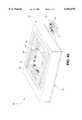
- FIG. 1is a top perspective view of an integrated circuit cooling apparatus that embodies principles of the present invention in a preferred form.
- FIG. 2is a perspective exploded view of the cooling apparatus of FIG. 1, showing the various key components thereof.
- FIGS. 3a and 3billustrate a preferred embodiment of the cold plate of the present invention for chilling an integrated circuit to below ambient temperatures.
- FIG. 4is an exploded perspective view of the thermal socket portion of the present invention illustrating the heating element and control circuit for maintaining the temperature of the projecting socket pins above a predetermined threshold.
- FIG. 4ais a perspective view of the thermal socket of FIG. 4 as it appears when assembled.
- FIG. 5is a perspective cut-away drawing showing a small portion of the heater board and illustrating a preferred method of electrically isolating the heating element from the socket pins that project through the heater board.
- FIG. 6is a side cross-sectional view of a small section of the heater board illustrating isolation of the heating element from the socket pins and a preferred method of sealing the socket pins within the heater board.
- FIG. 7is an electronic schematic diagram of a preferred thermostatic monitor and control circuit for maintaining the temperature of the exposed socket pins above a predetermined threshold.
- FIG. 1is a perspective view of an integrated circuit cooling apparatus that embodies principles of the present invention in a preferred form.
- the integrated circuit device illustrated in the drawingsis a computer CPU chip and the description that follows will be presented in the context of cooling a CPU. It should be understood, however, that the present invention is not limited to the cooling of CPUs but is equally applicable to the cooling of virtually any integrated circuit device that can benefit from lower operating temperatures.
- the apparatus 11comprises an outer casing 12 formed by an upper shell 13 and a lower shell 14.
- the shells 13 and 14preferably are formed of a sheet metal such as aluminum and are connected together to form the outer casing 12 my means of fasteners 17 such as, for example, bolts that extend through mating flanges 16.
- the outer casing 12encloses the thermal housing and other components of the present invention as described in more detail below. A portion of the thermal housing is visible at 18 in FIG. 1.
- the bottom of the outer casing(not visible in FIG. 1) is open to expose downwardly projecting socket pins that are coupled into the mother board or other printed circuit board of a computer in the usual way.
- a connector tab 23 of a heater boardprojects from the lower shell 14 of the casing 12 and includes a connector header 24 for connecting internal components of the heater board to an outside source of power and data.
- Coolant delivery line 19 and coolant return line 21are provided for delivering a coolant to a cold plate located within the casing 12 and an insulating sleeve 22 insulates and isolates the supply and return lines and prevents condensation thereon.
- the coolantwhich can be freon or a modern freon substitute, evaporates as it moves through the cold plate to cool the cold plate to below ambient temperatures and, in turn, to cool a CPU on which the cold plate is mounted.
- FIG. 2is an exploded perspective view of the invention illustrating the various internal components contained within the outer casing 12.
- the outer casingitself is omitted for clarity in FIG. 2.
- the functional components of the present inventioninclude a generally rectangular heater board 26 that forms the bottom plate or wall of the assembly.
- the heater board 26preferably is formed of standard printed circuit board material and includes a generally rectangular main board 83 and a connector tab 23 that projects from one side of the of the board.
- An electrical header or connector 24is mounted to the connector tab 23 and includes upwardly projecting prongs or pins for attaching the heater board and its various electronic components to an external source of power and data.
- the main board 83 of the heater board 26is punched or drilled to define an array of holes 27 that extend through the heater board 26 to its bottom side.
- the holes 27are arranged and configured to receive the pins of a CPU chip socket 31 for mounting the socket 31 to the heater board with its pins projecting through the heater board to exposed end portions.
- the exposed end portions of the socket pinscan then be mounted to a mother board or other printed circuit board in the usual way to couple the socket into an electronic circuit.
- a heating element 28is disposed on a top surface of the heater board 26.
- the heating element 28comprises a polymer thick film (PTF) resistor that is silk screen printed onto the heater board 26 surrounding and permeating the holes 27 formed therethrough.
- PTFpolymer thick film
- Opposed edge portions of the PTF resistoroverlie respective terminal strips 29, which preferably are formed of copper on the surface of the heater board 26 using standard printed circuit board etching technology.
- a generally rectangular insulating carrier 37is formed with an interior rectangular opening 38 and is sized to be mounted and sealed to the heater board 26 extending about the periphery thereof.
- the insulating carrier 37is molded from standard reaction injection molded (RIM) foam, which provides superior thermal insulation with minimum bulk and weight.
- the insulating carrier 37can be sealed to the peripheral portion of the heater board 26 by means of an appropriate epoxy and can be further secured if desired with fasteners that extend through openings 86 in the heater board and into the material of the insulating carrier 37.
- a gasket seat 39is formed in the top surface of the insulating carrier 37 and surrounds the central rectangular opening 38 formed therein.
- the central opening 38 of the insulated carrier 37is sized to receive and surround a socket 31 into which a CPU can be mounted.
- the socket 31is a standard CPU socket available from a number of electronic supply outlets and comprises a square or rectangular base 32 having an array of socket pins 33 embedded therein.
- the socket pins 33are formed with socket portions 34 that are exposed on the top surface of the base 32 for receiving the connector pins of a CPU chip 42, and elongated socket pins or legs 36 that project downwardly from the base for mounting to the heater board 26.
- the base 32 of the socketis embedded in and surrounded by the insulating carrier 37 with the top of the base substantially flush with the top of the carrier.
- the downwardly projecting legs 36 of the socket pinsextend through the holes 27 in the heater board 26 and extend a predetermined distance downwardly from the bottom surface of the heater board to exposed ends.
- the exposed downwardly projecting ends of the legs 36are then soldered or otherwise mounted to a mother board of a computer in the usual way. In this way, a CPU plugged into the socket 31 is directly coupled through the socket pins 33 to mother board of its computer as if it were mounted directly to the mother board itself.
- the insulating carrier 37actually be molded around the socket 31 in order to provide a tight and secure mechanical and thermal seal between the carrier 37 and the socket 31.
- thisis not a requirement of the invention and the carrier 37 could be molded separately from the socket 32 and the two assembled with epoxy or the like.
- a gasket 41preferably in the form of a rubber O-ring, is configured to be received in the gasket seat 39 formed in the insulating carrier 37.
- the gasket 41functions to provide a seal of high integrity between the upper surface of the insulating carrier 37 and the main insulator housing that is mounted atop the carrier as described in more detail below.
- a CPU chip 42 to be cooled by the present inventionhas an array of downwardly projecting connector pins 43.
- the chip 42 in the illustrated embodimentis provided with a heat spreader 44, which is formed from a thermally conducting material such as metal and is mounted to the top surface of the CPU chip.
- the heat spreader 44is formed with a pair of spaced upstanding posts 46 for improved thermal coupling to a cold plate as described in more detail below. It should be understood that while some CPU chips are provided with heat spreaders to aid in chip cooling, others are not. Thus, while the invention is illustrated in the drawings as accommodating a CPU chip with a heat spreader, such is not a limitation of the invention and the invention is equally effective in cooling chips without heat spreaders. Further, some heat spreaders are devoid of the upstanding posts 46.
- the present inventionis equally adaptable to all such CPU configurations and the particular configuration illustrated in the preferred embodiment should not be considered a limitation of the invention.
- the CPU 42is plugged into the socket 31 such that electrical connection is made between each connector pin 43 of the CPU and a corresponding socket pin 33 of the socket 31.
- a main insulator housing 45is formed by a lower section 47 and an upper section 50. Both the lower section 47 and the upper section 50 preferably are also molding from RIM foam because of its superior insulating and mechanical properties. However, other appropriate materials might be used with comparable results.
- the lower section 47 of the insulator housing 45is formed with a central opening 48 sized to receive and surround the CPU chip 42 when the lower section 47 of the insulator housing is mounted atop the insulating carrier 37.
- the gasket 41provides a seal between the insulating carrier 37 and the bottom surface of the lower section 47 when the two pieces are mounted together.
- a spline 49is formed in and projects upwardly from the top surface of the lower section 47 and substantially surrounds the opening 48 formed therein.
- the lower section 47is also formed with a downwardly projecting leg 51 along one side. The leg 51 is contoured and configured to define a portion of a passageway for enclosing and insulating coolant lines 62 of a cold plate as detailed below.
- the upper section 50 of the housing 45has a bottom surface 52 that is formed with a groove 53 sized and positioned to receive the spline 49 of the lower section 47 when the two sections are mounted together.
- the spline and groove configurationproperly aligns the two sections of the housing 45 and provides a seal between the two sections to prevent migration of ambient atmosphere into the device.
- An appropriate epoxy or other adhesivecan also be used to secure the sections together and enhance the seal formed therebetween.
- a leg 54projects downwardly from one side of the upper section 50 and is formed to compliment the leg 51 of the lower section such that when the two sections are joined together, the legs 51 and 54 define an enclosed insulated passageway for housing and insulating the coolant supply and return lines 62 of the cold plate 56.
- the cold plate 56is fabricated of thermally conductive material such as metal and has a pair of spaced openings 59 that are sized to receive the posts 46 of the heat spreader 44 on the CPU chip. Of course, in the case of heat spreaders without mounting posts, the cold plate 56 will have no spaced openings 59. In use, the cold plate 56 sits atop the heat spreader 44 of the CPU 52 with the posts 46 of the heat spreader extending through and being surrounded by the openings 59. In this way, when the cold plate 56 is chilled by introduction of coolant thereto, the heat spreader and CPU chip 42 are chilled in turn through thermal conduction of heat from the CPU to the cold plate. In practice, it is desired to chill the integrated circuit device 42 to a temperature of -40° C. or less in order to improve significantly the efficiency and operating speed of the chip. Such temperatures are easily achievable with the present invention.
- the interior or bottom surface 52 of the upper section 50 of the insulator housing 45is also formed with a pair of openings 61 that are sized and positioned to receive any portion of the posts 46 of the heat spreader 44 that project upwardly beyond the cold plate 56.
- a thermal plug 64is configured to plug the tops of the openings 61 and, for this purpose, has a pair of downwardly projecting prongs 66 that plug, seal, and insulate the tops of the holes 61.
- An insulating top cover 67is mounted to and covers the top of the entire assembly to provide closure and additional insulation.
- the thermal plug 64 and the top cover 67are also preferably molded from RIM foam.
- the CPU 42 and the socket 31become sealed within an insulated interior cavity defined by the main insulator housing 45, the insulating carrier 37, and the heater board 26.
- the cold plate 56sits atop the CPU within the cavity and, when chilled, cools the CPU down to a predetermined below ambient temperature.
- the CPUAs the CPU is chilled to below ambient temperatures by the cold plate, its connector pins 43 also become chilled through thermal conduction and, in turn, the socket pins 33 of the socket 31 in which the connector pins are disposed are also chilled to a very low temperature. Normally, the exposed end portions of the socket pins 33 that project below the heater board 26 would also become chilled through thermal conduction and such chilling would result in moisture condensation on the pins and surrounding components. However, with the present invention, such chilling of the exposed ends of the socket pins is prevented and condensation does not occur. This is accomplished by applying power to the heating element 28 on the upper surface of the heater board 26 within the sealed insulated chamber, which heats the heating element and this heat is transferred to the socket pins where they extend into the heater board. This heat is then conducted through the socket pins to their exposed external end portions to heat the exposed ends of the socket pins to a temperature above a predetermined threshold higher than the local ambient dew point.
- the predetermined threshold temperature of the socket pin endsis selected to be slightly greater than the ambient temperature inside a computer in which the present invention in employed. In this way, it is assured that the temperature of the exposed ends of the socket pins is always above the local dew point so that no moisture condensation is possible on the pins.
- a temperature monitoring and control circuitwhich is described in more detail below, is mounted to the heater board 26. The monitoring and control circuit constantly monitors the temperature of the projecting ends of the socket pins and applies power to the heating element 28 as necessary to insure that the temperature of the pins remains always above the predetermined threshold.
- FIGS. 3a and 3billustrate a preferred embodiment of the cover plate 58 and lower section 57 that, when secured together, form the cold plate 56 (FIG. 2).
- the cold plate 56(FIG. 2) comprises a lower section 57 (FIG. 3B) and an upper section or cover plate 56 (FIG. 3A). Both sections are formed from a material that is highly thermally conductive such as, for example, metal or another appropriate thermally conductive material.
- the lower section 57 of the cold plateis machined with a continuous serpentine channel 71 that snakes through the interior of the cold plate and surrounds the openings 59 formed therethrough.
- the cover plate 58is secured and sealed to the top of the lower section 57 forming a sealed serpentine passageway extending and snaking through the cold plate.
- Coolantsuch as freon or a freon substitute is then delivered to the coolant inlet 72 of the cold plate.
- the coolanttraverses the serpentine passageway in the cold plate, it changes state from a liquid to a gas and expands accordingly. Since this a highly endothermic process, the cold plate is quickly cooled to below ambient temperatures.
- the expanded gaseous coolantthen passes out of the cold plate through the coolant outlet 73 and is returned to an ancillary compressor for recompression back to a liquid state for recirculation.
- FIGS. 4 and 4aillustrate the thermal socket portion of the present invention in an exploded perspective and an assembled perspective view respectively.
- the purpose of this thermal socketis to prevent moisture condensation on the ends of the socket pins that project out of the assembly by maintaining these ends at a temperature above the local dew point.
- the thermal socket 85is comprised of the heater board 26, the socket 31, and the insulating carrier 37.
- the socket 31is of conventional construction and includes a base 32 into which is embedded an array of socket pins 33.
- Each of the socket pinshas an upper portion 34 defining a socket for receiving a corresponding connector pin of a CPU and an elongated depending pin portion 36 projecting downwardly from the base.
- the heater board 26which preferably is fabricated of standard printed circuit board material, has a generally rectangular field 83 from one side of which a connecting tab 23 projects.
- An array of pin receiving holes 27are formed through the heater board 26 and are spaced and arranged to receive the socket pins 33 of the socket 31.
- the socket 31When the socket 31 is mounted to the heater board 26, its pins extend through the heater board and project downwardly from the bottom surface thereof to exposed external end portions for mounting to a mother board or other circuit board.
- a heating element in the form of a PTF resistor 28is silk screen printed onto the upper surface of the heater board 26 surrounding the permeating the array of holes 27 formed therein.
- the thick film resistor 28overlies metal terminal strips 29 disposed along opposed edges of the film and the terminal strips 29 are provided with holes 84 for connecting the strips to an external source of electrical power.
- currentflows through the PTF resistor, causing it to heat through ohmic heating. This heat, in turn, is transferred through thermal conduction to the socket pins 33 that project through the heater board causing the exposed end portions of the socket pins to be heated.
- a connector header 24is mounted to the connecting tab 23 of the heater board for connecting electronic components 82 on the heater board to an external source of power and data.
- the insulating carrier 37has a central opening that surrounds and insulates the socket 31 when the insulated carrier 37 is mounted and sealed to the heater board 26 (FIG. 4a). When so assembled, the top surface of the socket 31 is flush with the top surface of the insulated carrier 37 and is poised to receive a CPU.
- FIG. 5illustrates a method of insuring such insulation and isolation. While only one socket pin and its corresponding heater board hole are shown in FIG. 5, it will be understood that each of the pins and holes are formed in a similar manner.
- a pin receiving hole 91which is slightly larger than the body 36 of the socket pin 33 is formed through the heater board 26.
- the PTF resistor heating element 28, which preferably is silk screen printed onto the heater board,is formed with an opening or void 92 that is centered on and surrounds the hole 91. This defines an isolation zone between the opening 91 and the heating element 28. Accordingly, when the socket pin 33 is inserted through the hole 91, it is spaced and electrically isolated from the material of the heating element 28. Thus, the socket pins are electrically isolated from the heating element so that no resistive connections are made between the pins and current flowing through the heating element does not interfere with signals transmitted through the socket pins 33. However, the heat generated by the heating element 28 is thermally coupled through the material of the heater board to the pins thus heating the exposed end portion of the socket pins beneath the heater board 26.
- FIG. 6is a side elevational partially sectioned view illustrating again the electrical isolation between the heating element 28 and the socket pins 36 and also illustrating a preferred means of sealing the socket pins in the heater board to prevent migration of ambient air into the sealed chamber of the cooling apparatus.
- each pin 36extends through a corresponding hole 91 formed through the heater board 26.
- the PTF resistor heating element 28, which is deposited on the top surface of the heater board 26,is formed with an opening 92 centered on each of the holes 91 that surrounds but does not contact the pin 36. The heating element 28 is thus electrically isolated from the pin 36.
- an annular metal gusset 93is printed on the bottom surface 90 of the heater board with standard printed circuit etching techniques.
- the pin 36extends both through the opening 91 in the heater board and through the annular gusset 93.
- Solder 94is then applied through solder reflow or other common circuit board soldering techniques to the pin and the gusset. The solder flows around the pin and bonds to the pin and the gusset to provide a mechanical seal of very high integrity and reliability.
- ambient atmosphereis prevented from seeping through the holes 91 into the sealed chamber containing the chilled CPU and, in this way, condensation inside the chamber is prevented.
- the temperature of the heating element 28rises through ohmic heating and this heat is transferred to the socket pins extending through the heater board 26.
- the temperature of the projecting exposed ends of the socket pinsis monitored and power is applied to the heating element as necessary to maintain the temperature of these exposed ends above a predetermined threshold.
- the predetermined thresholdis selected to be slightly higher than the ambient temperature. In this way, the below ambient temperatures of the socket pins inside the cooling device do not cause the exposed ends of the pins outside the cooling device to become chilled as well. Accordingly, condensation or moisture and its attendant problems is eliminated.
- FIG. 7is an electronic circuit diagram illustrating a preferred circuit for monitoring the temperature of the exposed pins and controlling the heating element accordingly.
- the circuitcomprises the PTF resistor heating element 106 that is connected to a source of power through a header 107 and to ground through a transistor switch 104.
- a digital thermostat 102in the form of an integrated circuit, preferably a DS1620 chip available from Dallas Semiconductor, is mounted to the bottom surface of the heater board in the region of and adjacent to the protruding exposed end portions of the socket pins.
- the digital thermostat 102receives operating power from an external power source through header 107 attached to the connector tab of the heating plate and filter capacitors 103 are employed to filter the operating voltage.
- the digital thermostat chip 102operates as follows. A predetermined low temperature set point and a predetermined high temperature set point are programmed into the digital thermostat chip from an external source through the header 107. If the ambient temperature in the vicinity of the chip falls below the low temperature set point, the output of the chip becomes high. If the temperature in the vicinity of the chip rises above the high temperature set point, the output of the chip becomes low. The output of the chip 102 is coupled through the header 107 to the base of transistor 104. When the output of the chip goes high, the transistor is turned on and connects the heater 106 and power source from the header 107 to ground. Current thus begins to flow through the heater and begins to heat the projecting pins.
- the digital thermostat 102senses that the temperature of the pin ends has risen above the high temperature set point, the output of the thermostat 102 goes low and the transistor 104 is turned off disconnecting the PTF heater from its power source. The temperature of the exposed pin ends then begins to fall until it falls below the low set point again and the cycle repeats. In this way the temperature of the projecting exposed pins of the device are maintained at a temperature within the range defined by the low and high temperature set points, which preferably is slightly higher than the local ambient temperature, and the heater is activated only as necessary to maintain such a condition.
- the inventionhas been described in terms of preferred embodiments and methodologies. It will be obvious to those of skill in the art, however, that various modifications and extensions of the preferred embodiments might well be made.
- the method of the present inventionis applicable to the prevention of condensation on exposed elements of any device where a component is chilled within a chamber and exposed elements projecting from the chamber are subject to becoming chilled through thermal conduction.
- the preferred embodiment of the inventionis directed to chips having traditional metal connector pins. In some modern CPU circuits, the CPU and perhaps other related components are mounted on their own small circuit board. This circuit board is then coupled to the main mother board with an edge connector.
Landscapes
- Engineering & Computer Science (AREA)
- Microelectronics & Electronic Packaging (AREA)
- Physics & Mathematics (AREA)
- Condensed Matter Physics & Semiconductors (AREA)
- General Physics & Mathematics (AREA)
- Computer Hardware Design (AREA)
- Power Engineering (AREA)
- Cooling Or The Like Of Semiconductors Or Solid State Devices (AREA)
Abstract
Description
Claims (24)
Priority Applications (1)
| Application Number | Priority Date | Filing Date | Title |
|---|---|---|---|
| US09/020,766US6054676A (en) | 1998-02-09 | 1998-02-09 | Method and apparatus for cooling an integrated circuit device |
Applications Claiming Priority (1)
| Application Number | Priority Date | Filing Date | Title |
|---|---|---|---|
| US09/020,766US6054676A (en) | 1998-02-09 | 1998-02-09 | Method and apparatus for cooling an integrated circuit device |
Publications (1)
| Publication Number | Publication Date |
|---|---|
| US6054676Atrue US6054676A (en) | 2000-04-25 |
Family
ID=21800449
Family Applications (1)
| Application Number | Title | Priority Date | Filing Date |
|---|---|---|---|
| US09/020,766Expired - Fee RelatedUS6054676A (en) | 1998-02-09 | 1998-02-09 | Method and apparatus for cooling an integrated circuit device |
Country Status (1)
| Country | Link |
|---|---|
| US (1) | US6054676A (en) |
Cited By (65)
| Publication number | Priority date | Publication date | Assignee | Title |
|---|---|---|---|---|
| WO2001025881A2 (en) | 1999-10-04 | 2001-04-12 | Asetek A/S | Computer system comprising a cooling system |
| US6219245B1 (en)* | 2000-04-18 | 2001-04-17 | General Motors Corporation | Electrically isolated power switching device mounting assembly for EMI reduction |
| US6243268B1 (en)* | 1999-10-12 | 2001-06-05 | International Business Machines Corporation | Cooled IC chip modules with an insulated circuit board |
| US6246581B1 (en)* | 1999-10-12 | 2001-06-12 | International Business Machines Corporation | Heated PCB interconnect for cooled IC chip modules |
| US6250085B1 (en)* | 1999-05-26 | 2001-06-26 | Eliahou Tousson | Temperature self-regulated integrated circuits and devices |
| US6283435B1 (en)* | 2000-02-02 | 2001-09-04 | Chiang Ming Huang | Structure of a CPU securing seat |
| US6292365B1 (en)* | 1998-09-18 | 2001-09-18 | Hitachi, Ltd. | Electronic apparatus |
| US6320756B1 (en)* | 1999-01-18 | 2001-11-20 | Alps Electric Co., Ltd. | Electronic device mounting structure using electronic device mounting member and cushioning |
| US6377459B1 (en) | 2000-08-04 | 2002-04-23 | Sun Microsystems, Inc. | Chip cooling management |
| US6446447B1 (en)* | 2001-06-29 | 2002-09-10 | International Business Machines Corporation | Logic module refrigeration system with condensation control |
| US6483078B2 (en)* | 2000-02-09 | 2002-11-19 | Oceanit Laboratories, Inc. | Moisture control system for electrical devices |
| US20020175404A1 (en)* | 2001-05-24 | 2002-11-28 | Nec Corporation | Electronic device having dewing prevention structure and dewing prevention structure of electronic device |
| WO2003010646A1 (en)* | 2001-07-24 | 2003-02-06 | Kryotech, Inc. | Integrated circuit cooling apparatus |
| US6523362B2 (en)* | 2001-01-09 | 2003-02-25 | Abb Research Ltd | Support for components used in microsystems technology |
| US6564563B2 (en) | 2001-06-29 | 2003-05-20 | International Business Machines Corporation | Logic module refrigeration system with condensation control |
| US20030111340A1 (en)* | 2001-12-18 | 2003-06-19 | Dionex Corporation | Disposable working electrode for an electrochemical cell |
| US6621071B2 (en)* | 2001-09-07 | 2003-09-16 | Raytheon Co. | Microelectronic system with integral cryocooler, and its fabrication and use |
| US6637231B1 (en) | 2002-06-28 | 2003-10-28 | Sun Microsystems, Inc. | Field replaceable packaged refrigeration heat sink module for cooling electronic components |
| US6668570B2 (en) | 2001-05-31 | 2003-12-30 | Kryotech, Inc. | Apparatus and method for controlling the temperature of an electronic device under test |
| US6687122B2 (en) | 2001-08-30 | 2004-02-03 | Sun Microsystems, Inc. | Multiple compressor refrigeration heat sink module for cooling electronic components |
| US20040059782A1 (en)* | 2002-09-20 | 2004-03-25 | American Megatrends, Inc. | Systems and methods for establishing interaction between a local computer and a remote computer |
| US20040070927A1 (en)* | 2001-02-14 | 2004-04-15 | Morten Espersen | Cooling arrangement for an integrated circuit |
| US6741469B1 (en) | 2003-02-07 | 2004-05-25 | Sun Microsystems, Inc. | Refrigeration cooling assisted MEMS-based micro-channel cooling system |
| US20040190773A1 (en)* | 2003-03-31 | 2004-09-30 | American Megatrends, Inc. | Method, apparatus, and computer-readable medium for identifying character coordinates |
| US6825557B2 (en) | 2002-12-17 | 2004-11-30 | Intel Corporation | Localized backside chip cooling with integrated smart valves |
| US20040243883A1 (en)* | 2003-05-27 | 2004-12-02 | American Megatrends, Inc. | Method and system for remote software debugging |
| US20040255276A1 (en)* | 2003-06-16 | 2004-12-16 | Gene Rovang | Method and system for remote software testing |
| US20050049584A1 (en)* | 2001-02-02 | 2005-03-03 | Lumineyes, Llc | Techniques for alteration of iris pigment |
| US20050046637A1 (en)* | 2001-12-10 | 2005-03-03 | American Megatrends, Inc. | Systems and methods for capturing screen displays from a host computing system for display at a remote terminal |
| US20050123418A1 (en)* | 2003-12-08 | 2005-06-09 | Manole Dan M. | Compact compressors and refrigeration systems |
| US6975028B1 (en) | 2003-03-19 | 2005-12-13 | Delta Design, Inc. | Thermal apparatus for engaging electronic device |
| US20060090494A1 (en)* | 2004-11-01 | 2006-05-04 | Manole Dan M | Compact refrigeration system for providing multiple levels of cooling |
| US7044768B1 (en)* | 2003-10-23 | 2006-05-16 | Isothermal Systems Research, Inc. | Liquid thermal management socket system |
| US20060101837A1 (en)* | 2004-11-12 | 2006-05-18 | Manole Dan M | Compact refrigeration system and power supply unit including dynamic insulation |
| US20060152903A1 (en)* | 2005-01-10 | 2006-07-13 | Cohen Alan M | Heat dissipation assembly for computing devices |
| US20070002539A1 (en)* | 2005-06-30 | 2007-01-04 | Intel Corporation | Chamber sealing valve |
| US20070168746A1 (en)* | 2005-12-14 | 2007-07-19 | Stefano Righi | System and method for debugging a target computer using SMBus |
| CN100403526C (en)* | 2004-11-18 | 2008-07-16 | 丰田自动车株式会社 | Heat dissipation structure of semiconductor device and semiconductor package |
| US20090032934A1 (en)* | 2006-04-20 | 2009-02-05 | Rosenberger Hochfrequenztechnik Gmbh & Co. Kg | Potential-free housing leadthrough |
| US7519749B1 (en) | 2004-08-25 | 2009-04-14 | American Megatrends, Inc. | Redirecting input and output for multiple computers |
| US7543277B1 (en) | 2003-06-27 | 2009-06-02 | American Megatrends, Inc. | Method and system for remote software debugging |
| US7783799B1 (en) | 2006-08-31 | 2010-08-24 | American Megatrends, Inc. | Remotely controllable switch and testing methods using same |
| US7827258B1 (en) | 2004-03-01 | 2010-11-02 | American Megatrends, Inc. | Method, system, and apparatus for communicating with a computer management device |
| US20110030754A1 (en)* | 2009-08-06 | 2011-02-10 | Laird Technologies, Inc. | Thermoelectric modules and related methods |
| US20110079033A1 (en)* | 2008-06-12 | 2011-04-07 | Noriyuki Okuda | Air conditioner |
| US20110197609A1 (en)* | 2007-10-16 | 2011-08-18 | Kim Tiow Ooi | heat transfer system and method |
| US20140016261A1 (en)* | 2012-07-10 | 2014-01-16 | Moxa Inc. | Heating and heat dissipating multi-layer circuit board structure for keeping operating temperature of electronic components |
| US8649179B2 (en) | 2011-02-05 | 2014-02-11 | Laird Technologies, Inc. | Circuit assemblies including thermoelectric modules |
| US20150009630A1 (en)* | 2013-07-02 | 2015-01-08 | Wistron Corporation | Electronic signal transmitting device and integrated circuit thereof |
| US20150233848A1 (en)* | 2012-05-31 | 2015-08-20 | 3M Innnovative Properties Company | Electronic indicator device for cleaning monitoring |
| US20150309114A1 (en)* | 2009-11-30 | 2015-10-29 | Essai, Inc. | Systems and methods for conforming test tooling to integrated circuit device with heater socket |
| US9357675B2 (en) | 2013-10-21 | 2016-05-31 | International Business Machines Corporation | Pump-enhanced, immersion-cooling of electronic component(s) |
| US20170192471A1 (en)* | 2015-12-30 | 2017-07-06 | Cooler Master Co., Ltd. | Cooling apparatus for electronic components |
| US9772664B1 (en)* | 2016-03-25 | 2017-09-26 | Adlink Technology Inc. | Memory heater and heating aid arrangement |
| US10409341B2 (en) | 2016-02-15 | 2019-09-10 | Cooler Master Co., Ltd. | Cooling apparatus |
| US10410955B2 (en) | 2015-01-28 | 2019-09-10 | Cooler Master Co., Ltd. | Liquid cooling heat sink structure and cooling circulation system thereof |
| US10432174B2 (en) | 2002-04-16 | 2019-10-01 | Facebook, Inc. | Closed loop feedback control of integrated circuits |
| US10739084B2 (en) | 2015-01-28 | 2020-08-11 | Cooler Master Co., Ltd. | Liquid cooling heat sink structure and cooling circulation system thereof |
| US20200351990A1 (en)* | 2017-10-23 | 2020-11-05 | Acquire Industries Ltd | Planar electrical heating apparatus with modular assembly |
| US10975876B2 (en) | 2019-04-19 | 2021-04-13 | Cooler Master Co., Ltd. | Cooling device |
| US20210410327A1 (en)* | 2019-05-10 | 2021-12-30 | Cooler Master Co., Ltd. | Liquid cooling device |
| US11460036B2 (en) | 2019-10-07 | 2022-10-04 | Cooler Master Co., Ltd. | Light emitting fan device and non-light emitting fan device |
| US11460035B2 (en) | 2019-10-07 | 2022-10-04 | Cooler Master Co., Ltd. | Light emitting fan device and non-light emitting fan device |
| US12099385B2 (en) | 2016-02-15 | 2024-09-24 | Cooler Master Co., Ltd. | Cooling apparatus |
| US12158786B2 (en) | 2016-02-15 | 2024-12-03 | Cooler Master Co., Ltd. | Cooling apparatus |
Citations (25)
| Publication number | Priority date | Publication date | Assignee | Title |
|---|---|---|---|---|
| US3412566A (en)* | 1965-06-21 | 1968-11-26 | Borg Warner | Thermoelectric apparatus |
| US3786172A (en)* | 1972-12-07 | 1974-01-15 | Accra Point Arrays Corp | Printed circuit board method and apparatus |
| US4394711A (en)* | 1979-06-01 | 1983-07-19 | Interconnection Technology, Inc. | Circuit board with weldable terminals |
| US4481403A (en)* | 1983-03-04 | 1984-11-06 | Honeywell Inc. | Temperature control of solid state circuit chips |
| US5040381A (en)* | 1990-04-19 | 1991-08-20 | Prime Computer, Inc. | Apparatus for cooling circuits |
| US5089688A (en)* | 1984-07-10 | 1992-02-18 | Raychem Corporation | Composite circuit protection devices |
| US5148003A (en)* | 1990-11-28 | 1992-09-15 | International Business Machines Corporation | Modular test oven |
| US5329426A (en)* | 1993-03-22 | 1994-07-12 | Digital Equipment Corporation | Clip-on heat sink |
| US5343358A (en)* | 1993-04-26 | 1994-08-30 | Ncr Corporation | Apparatus for cooling electronic devices |
| US5365749A (en)* | 1993-12-23 | 1994-11-22 | Ncr Corporation | Computer component cooling system with local evaporation of refrigerant |
| US5427984A (en)* | 1993-03-01 | 1995-06-27 | At&T Global Information Solutions | Method of making a cooling package for a semiconductor chip |
| US5440172A (en)* | 1993-06-28 | 1995-08-08 | Sundstrand Corporation | Integral heat sink interface |
| US5473508A (en)* | 1994-05-31 | 1995-12-05 | At&T Global Information Solutions Company | Focused CPU air cooling system including high efficiency heat exchanger |
| US5476399A (en)* | 1994-05-20 | 1995-12-19 | At&T Global Information Solutions Company | High frequency/low temperature electronic socket pin |
| US5489750A (en)* | 1993-03-11 | 1996-02-06 | Matsushita Electric Industrial Co., Ltd. | Method of mounting an electronic part with bumps on a circuit board |
| US5495394A (en)* | 1994-12-19 | 1996-02-27 | At&T Global Information Solutions Company | Three dimensional die packaging in multi-chip modules |
| US5513152A (en)* | 1994-06-22 | 1996-04-30 | At&T Global Information Solutions Company | Circuit and method for determining the operating performance of an integrated circuit |
| US5515683A (en)* | 1992-09-22 | 1996-05-14 | Litef Gmbh | Thermoelectric heating or cooling device |
| US5549155A (en)* | 1995-04-18 | 1996-08-27 | Thermacore, Inc. | Integrated circuit cooling apparatus |
| US5574627A (en)* | 1995-07-24 | 1996-11-12 | At&T Global Information Solutions Company | Apparatus for preventing the formation of condensation on sub-cooled integrated circuit devices |
| US5581441A (en)* | 1995-06-07 | 1996-12-03 | At&T Global Information Solutions Company | Electrically-operated heat exchanger release mechanism |
| US5594609A (en)* | 1994-04-23 | 1997-01-14 | Lin; Wei T. | Thermoelectric couple device |
| US5613364A (en)* | 1995-10-06 | 1997-03-25 | Pou, Inc. | Compact replaceable temperature control module |
| US5821505A (en)* | 1997-04-04 | 1998-10-13 | Unisys Corporation | Temperature control system for an electronic device which achieves a quick response by interposing a heater between the device and a heat sink |
| US5844208A (en)* | 1997-04-04 | 1998-12-01 | Unisys Corporation | Temperature control system for an electronic device in which device temperature is estimated from heater temperature and heat sink temperature |
- 1998
- 1998-02-09USUS09/020,766patent/US6054676A/ennot_activeExpired - Fee Related
Patent Citations (25)
| Publication number | Priority date | Publication date | Assignee | Title |
|---|---|---|---|---|
| US3412566A (en)* | 1965-06-21 | 1968-11-26 | Borg Warner | Thermoelectric apparatus |
| US3786172A (en)* | 1972-12-07 | 1974-01-15 | Accra Point Arrays Corp | Printed circuit board method and apparatus |
| US4394711A (en)* | 1979-06-01 | 1983-07-19 | Interconnection Technology, Inc. | Circuit board with weldable terminals |
| US4481403A (en)* | 1983-03-04 | 1984-11-06 | Honeywell Inc. | Temperature control of solid state circuit chips |
| US5089688A (en)* | 1984-07-10 | 1992-02-18 | Raychem Corporation | Composite circuit protection devices |
| US5040381A (en)* | 1990-04-19 | 1991-08-20 | Prime Computer, Inc. | Apparatus for cooling circuits |
| US5148003A (en)* | 1990-11-28 | 1992-09-15 | International Business Machines Corporation | Modular test oven |
| US5515683A (en)* | 1992-09-22 | 1996-05-14 | Litef Gmbh | Thermoelectric heating or cooling device |
| US5427984A (en)* | 1993-03-01 | 1995-06-27 | At&T Global Information Solutions | Method of making a cooling package for a semiconductor chip |
| US5489750A (en)* | 1993-03-11 | 1996-02-06 | Matsushita Electric Industrial Co., Ltd. | Method of mounting an electronic part with bumps on a circuit board |
| US5329426A (en)* | 1993-03-22 | 1994-07-12 | Digital Equipment Corporation | Clip-on heat sink |
| US5343358A (en)* | 1993-04-26 | 1994-08-30 | Ncr Corporation | Apparatus for cooling electronic devices |
| US5440172A (en)* | 1993-06-28 | 1995-08-08 | Sundstrand Corporation | Integral heat sink interface |
| US5365749A (en)* | 1993-12-23 | 1994-11-22 | Ncr Corporation | Computer component cooling system with local evaporation of refrigerant |
| US5594609A (en)* | 1994-04-23 | 1997-01-14 | Lin; Wei T. | Thermoelectric couple device |
| US5476399A (en)* | 1994-05-20 | 1995-12-19 | At&T Global Information Solutions Company | High frequency/low temperature electronic socket pin |
| US5473508A (en)* | 1994-05-31 | 1995-12-05 | At&T Global Information Solutions Company | Focused CPU air cooling system including high efficiency heat exchanger |
| US5513152A (en)* | 1994-06-22 | 1996-04-30 | At&T Global Information Solutions Company | Circuit and method for determining the operating performance of an integrated circuit |
| US5495394A (en)* | 1994-12-19 | 1996-02-27 | At&T Global Information Solutions Company | Three dimensional die packaging in multi-chip modules |
| US5549155A (en)* | 1995-04-18 | 1996-08-27 | Thermacore, Inc. | Integrated circuit cooling apparatus |
| US5581441A (en)* | 1995-06-07 | 1996-12-03 | At&T Global Information Solutions Company | Electrically-operated heat exchanger release mechanism |
| US5574627A (en)* | 1995-07-24 | 1996-11-12 | At&T Global Information Solutions Company | Apparatus for preventing the formation of condensation on sub-cooled integrated circuit devices |
| US5613364A (en)* | 1995-10-06 | 1997-03-25 | Pou, Inc. | Compact replaceable temperature control module |
| US5821505A (en)* | 1997-04-04 | 1998-10-13 | Unisys Corporation | Temperature control system for an electronic device which achieves a quick response by interposing a heater between the device and a heat sink |
| US5844208A (en)* | 1997-04-04 | 1998-12-01 | Unisys Corporation | Temperature control system for an electronic device in which device temperature is estimated from heater temperature and heat sink temperature |
Cited By (129)
| Publication number | Priority date | Publication date | Assignee | Title |
|---|---|---|---|---|
| US6292365B1 (en)* | 1998-09-18 | 2001-09-18 | Hitachi, Ltd. | Electronic apparatus |
| US6320756B1 (en)* | 1999-01-18 | 2001-11-20 | Alps Electric Co., Ltd. | Electronic device mounting structure using electronic device mounting member and cushioning |
| US6250085B1 (en)* | 1999-05-26 | 2001-06-26 | Eliahou Tousson | Temperature self-regulated integrated circuits and devices |
| WO2001025881A2 (en) | 1999-10-04 | 2001-04-12 | Asetek A/S | Computer system comprising a cooling system |
| US6243268B1 (en)* | 1999-10-12 | 2001-06-05 | International Business Machines Corporation | Cooled IC chip modules with an insulated circuit board |
| US6246581B1 (en)* | 1999-10-12 | 2001-06-12 | International Business Machines Corporation | Heated PCB interconnect for cooled IC chip modules |
| US6283435B1 (en)* | 2000-02-02 | 2001-09-04 | Chiang Ming Huang | Structure of a CPU securing seat |
| US6483078B2 (en)* | 2000-02-09 | 2002-11-19 | Oceanit Laboratories, Inc. | Moisture control system for electrical devices |
| US6219245B1 (en)* | 2000-04-18 | 2001-04-17 | General Motors Corporation | Electrically isolated power switching device mounting assembly for EMI reduction |
| US6377459B1 (en) | 2000-08-04 | 2002-04-23 | Sun Microsystems, Inc. | Chip cooling management |
| US6523362B2 (en)* | 2001-01-09 | 2003-02-25 | Abb Research Ltd | Support for components used in microsystems technology |
| US20050049584A1 (en)* | 2001-02-02 | 2005-03-03 | Lumineyes, Llc | Techniques for alteration of iris pigment |
| CN100355062C (en)* | 2001-02-14 | 2007-12-12 | 希普根Aps公司 | A cooling arrangement for an integrated circuit |
| US20040070927A1 (en)* | 2001-02-14 | 2004-04-15 | Morten Espersen | Cooling arrangement for an integrated circuit |
| US7042723B2 (en)* | 2001-02-14 | 2006-05-09 | Extreme Cooling Technology Aps | Cooling arrangement for an integrated circuit |
| US20020175404A1 (en)* | 2001-05-24 | 2002-11-28 | Nec Corporation | Electronic device having dewing prevention structure and dewing prevention structure of electronic device |
| US6853071B2 (en)* | 2001-05-24 | 2005-02-08 | Nec Corporation | Electronic device having dewing prevention structure and dewing prevention structure of electronic device |
| US20040139756A1 (en)* | 2001-05-31 | 2004-07-22 | Wall Charles B. | Apparatus and method for controlling the temperature of an electronic device under test |
| US6993922B2 (en) | 2001-05-31 | 2006-02-07 | Delta Design, Inc. | Apparatus and method for controlling the temperature of an electronic device under test |
| US6668570B2 (en) | 2001-05-31 | 2003-12-30 | Kryotech, Inc. | Apparatus and method for controlling the temperature of an electronic device under test |
| US6644048B2 (en) | 2001-06-29 | 2003-11-11 | International Business Machines Corporation | Method for shutting down a refrigerating unit |
| US6644056B2 (en) | 2001-06-29 | 2003-11-11 | International Business Machines Corporation | Method of controlling a refrigeration unit |
| US6644053B2 (en) | 2001-06-29 | 2003-11-11 | International Business Machines Corporation | Method for starting a refrigeration unit |
| US6662577B2 (en) | 2001-06-29 | 2003-12-16 | Gary F. Goth | Method for operating a logic module refrigeration unit |
| US6595018B2 (en) | 2001-06-29 | 2003-07-22 | International Business Machines Corporation | Logic module refrigeration system with condensation control |
| US6698216B2 (en) | 2001-06-29 | 2004-03-02 | International Business Machines Corporation | Method for controlling a refrigeration unit for evaporator maintenance |
| US6698218B2 (en) | 2001-06-29 | 2004-03-02 | International Business Machines Corporation | Method for controlling multiple refrigeration units |
| US6446447B1 (en)* | 2001-06-29 | 2002-09-10 | International Business Machines Corporation | Logic module refrigeration system with condensation control |
| US6564563B2 (en) | 2001-06-29 | 2003-05-20 | International Business Machines Corporation | Logic module refrigeration system with condensation control |
| WO2003010646A1 (en)* | 2001-07-24 | 2003-02-06 | Kryotech, Inc. | Integrated circuit cooling apparatus |
| US6543246B2 (en)* | 2001-07-24 | 2003-04-08 | Kryotech, Inc. | Integrated circuit cooling apparatus |
| US6687122B2 (en) | 2001-08-30 | 2004-02-03 | Sun Microsystems, Inc. | Multiple compressor refrigeration heat sink module for cooling electronic components |
| US7178345B2 (en) | 2001-09-07 | 2007-02-20 | Ratheon Company | Stacked-plate gas-expansion cooler assembly, fabrication method, and use |
| US20060180752A1 (en)* | 2001-09-07 | 2006-08-17 | Sobel Larry D | Stacked-plate gas-expansion cooler assembly, fabrication method, and use |
| US6621071B2 (en)* | 2001-09-07 | 2003-09-16 | Raytheon Co. | Microelectronic system with integral cryocooler, and its fabrication and use |
| US7233336B2 (en) | 2001-12-10 | 2007-06-19 | American Megatrends, Inc. | Systems and methods for capturing screen displays from a host computing system for display at a remote terminal |
| US20050046637A1 (en)* | 2001-12-10 | 2005-03-03 | American Megatrends, Inc. | Systems and methods for capturing screen displays from a host computing system for display at a remote terminal |
| US20030111340A1 (en)* | 2001-12-18 | 2003-06-19 | Dionex Corporation | Disposable working electrode for an electrochemical cell |
| US10432174B2 (en) | 2002-04-16 | 2019-10-01 | Facebook, Inc. | Closed loop feedback control of integrated circuits |
| US6637231B1 (en) | 2002-06-28 | 2003-10-28 | Sun Microsystems, Inc. | Field replaceable packaged refrigeration heat sink module for cooling electronic components |
| US6894906B2 (en)* | 2002-09-20 | 2005-05-17 | American Megatrends, Inc. | Housing for in-line video, keyboard and mouse remote management unit |
| US7454490B2 (en) | 2002-09-20 | 2008-11-18 | American Megatrends, Inc. | In-line video, keyboard and mouse remote management unit |
| US20040059782A1 (en)* | 2002-09-20 | 2004-03-25 | American Megatrends, Inc. | Systems and methods for establishing interaction between a local computer and a remote computer |
| US7260624B2 (en) | 2002-09-20 | 2007-08-21 | American Megatrends, Inc. | Systems and methods for establishing interaction between a local computer and a remote computer |
| US20040236833A1 (en)* | 2002-09-20 | 2004-11-25 | American Megatrands, Inc. | Housing for in-line video, keyboard and mouse remote management unit |
| US6825557B2 (en) | 2002-12-17 | 2004-11-30 | Intel Corporation | Localized backside chip cooling with integrated smart valves |
| US6741469B1 (en) | 2003-02-07 | 2004-05-25 | Sun Microsystems, Inc. | Refrigeration cooling assisted MEMS-based micro-channel cooling system |
| US6975028B1 (en) | 2003-03-19 | 2005-12-13 | Delta Design, Inc. | Thermal apparatus for engaging electronic device |
| US20050280144A1 (en)* | 2003-03-19 | 2005-12-22 | Wayburn Lewis S | Thermal apparatus for engaging electronic device |
| US7418141B2 (en) | 2003-03-31 | 2008-08-26 | American Megatrends, Inc. | Method, apparatus, and computer-readable medium for identifying character coordinates |
| US20040190773A1 (en)* | 2003-03-31 | 2004-09-30 | American Megatrends, Inc. | Method, apparatus, and computer-readable medium for identifying character coordinates |
| US7412625B2 (en) | 2003-05-27 | 2008-08-12 | American Megatrends, Inc. | Method and system for remote software debugging |
| US20040243883A1 (en)* | 2003-05-27 | 2004-12-02 | American Megatrends, Inc. | Method and system for remote software debugging |
| US20040255276A1 (en)* | 2003-06-16 | 2004-12-16 | Gene Rovang | Method and system for remote software testing |
| US7945899B2 (en) | 2003-06-16 | 2011-05-17 | American Megatrends, Inc. | Method and system for remote software testing |
| US8539435B1 (en) | 2003-06-16 | 2013-09-17 | American Megatrends, Inc. | Method and system for remote software testing |
| US20090235122A1 (en)* | 2003-06-16 | 2009-09-17 | Gene Rovang | Method and System for Remote Software Testing |
| US7546584B2 (en) | 2003-06-16 | 2009-06-09 | American Megatrends, Inc. | Method and system for remote software testing |
| US8898638B1 (en) | 2003-06-27 | 2014-11-25 | American Megatrends, Inc. | Method and system for remote software debugging |
| US8046743B1 (en) | 2003-06-27 | 2011-10-25 | American Megatrends, Inc. | Method and system for remote software debugging |
| US7543277B1 (en) | 2003-06-27 | 2009-06-02 | American Megatrends, Inc. | Method and system for remote software debugging |
| US7044768B1 (en)* | 2003-10-23 | 2006-05-16 | Isothermal Systems Research, Inc. | Liquid thermal management socket system |
| US20050123418A1 (en)* | 2003-12-08 | 2005-06-09 | Manole Dan M. | Compact compressors and refrigeration systems |
| US8359384B2 (en) | 2004-03-01 | 2013-01-22 | American Megatrends, Inc. | Method, system, and apparatus for communicating with a computer management device |
| US7827258B1 (en) | 2004-03-01 | 2010-11-02 | American Megatrends, Inc. | Method, system, and apparatus for communicating with a computer management device |
| US20110015918A1 (en)* | 2004-03-01 | 2011-01-20 | American Megatrends, Inc. | Method, system, and apparatus for communicating with a computer management device |
| US7861020B1 (en) | 2004-08-25 | 2010-12-28 | American Megatrends, Inc. | Redirecting input and output for multiple computers |
| US7519749B1 (en) | 2004-08-25 | 2009-04-14 | American Megatrends, Inc. | Redirecting input and output for multiple computers |
| US20110066773A1 (en)* | 2004-08-25 | 2011-03-17 | American Megatrends, Inc. | Redirecting input and output for multiple computers |
| US7840728B1 (en) | 2004-08-25 | 2010-11-23 | American Megatrends, Inc. | Redirecting input and output for multiple computers |
| US8001302B2 (en) | 2004-08-25 | 2011-08-16 | American Megatrends, Inc. | Redirecting input and output for multiple computers |
| US7793019B1 (en) | 2004-08-25 | 2010-09-07 | American Megatrends, Inc. | Redirecting input and output for multiple computers |
| US7478541B2 (en) | 2004-11-01 | 2009-01-20 | Tecumseh Products Company | Compact refrigeration system for providing multiple levels of cooling |
| US20060090494A1 (en)* | 2004-11-01 | 2006-05-04 | Manole Dan M | Compact refrigeration system for providing multiple levels of cooling |
| US7617696B2 (en) | 2004-11-12 | 2009-11-17 | Tecumseh Products Company | Compact refrigeration system and power supply unit including dynamic insulation |
| US20060101837A1 (en)* | 2004-11-12 | 2006-05-18 | Manole Dan M | Compact refrigeration system and power supply unit including dynamic insulation |
| CN100403526C (en)* | 2004-11-18 | 2008-07-16 | 丰田自动车株式会社 | Heat dissipation structure of semiconductor device and semiconductor package |
| US20080106863A1 (en)* | 2005-01-10 | 2008-05-08 | Cohen Alan M | Heat dissipation assembly for computing devices |
| US7595987B2 (en)* | 2005-01-10 | 2009-09-29 | H. Christian Gunderson | Heat dissipation assembly for computing devices |
| US7551441B2 (en)* | 2005-01-10 | 2009-06-23 | H Christian Gunderson | Heat dissipation assembly for computing devices |
| US20080101012A1 (en)* | 2005-01-10 | 2008-05-01 | Cohen Alan M | Heat dissipation assembly for computing devices |
| US7292437B2 (en)* | 2005-01-10 | 2007-11-06 | Alan Mark Cohen | Heat dissipation assembly for computing devices |
| US20060152903A1 (en)* | 2005-01-10 | 2006-07-13 | Cohen Alan M | Heat dissipation assembly for computing devices |
| US7418998B2 (en) | 2005-06-30 | 2008-09-02 | Intel Corporation | Chamber sealing valve |
| US20070002539A1 (en)* | 2005-06-30 | 2007-01-04 | Intel Corporation | Chamber sealing valve |
| US7836748B2 (en) | 2005-06-30 | 2010-11-23 | Intel Corporation | Chamber sealing valve |
| US20080282775A1 (en)* | 2005-06-30 | 2008-11-20 | Intel Corporation | Chamber sealing valve |
| US20070168746A1 (en)* | 2005-12-14 | 2007-07-19 | Stefano Righi | System and method for debugging a target computer using SMBus |
| US8566644B1 (en) | 2005-12-14 | 2013-10-22 | American Megatrends, Inc. | System and method for debugging a target computer using SMBus |
| US8010843B2 (en) | 2005-12-14 | 2011-08-30 | American Megatrends, Inc. | System and method for debugging a target computer using SMBus |
| US20090032934A1 (en)* | 2006-04-20 | 2009-02-05 | Rosenberger Hochfrequenztechnik Gmbh & Co. Kg | Potential-free housing leadthrough |
| US7880294B2 (en)* | 2006-04-20 | 2011-02-01 | Rosenberger Hochfrequenztechnik Gmbh & Co. Kg | Potential-free housing leadthrough |
| KR101280903B1 (en)* | 2006-04-20 | 2013-07-02 | 로젠버거 호흐프리쿠벤츠테흐닉 게엠베하 운트 코. 카게 | Potential-free housing construction |
| US7979610B2 (en) | 2006-08-31 | 2011-07-12 | American Megatrends, Inc. | Remotely controllable switch and testing methods using same |
| US7783799B1 (en) | 2006-08-31 | 2010-08-24 | American Megatrends, Inc. | Remotely controllable switch and testing methods using same |
| US20110040904A1 (en)* | 2006-08-31 | 2011-02-17 | American Megatrends, Inc. | Remotely controllable switch and testing methods using same |
| US20110197609A1 (en)* | 2007-10-16 | 2011-08-18 | Kim Tiow Ooi | heat transfer system and method |
| US8464548B2 (en)* | 2008-06-12 | 2013-06-18 | Daikin Industries, Ltd. | Air conditioner |
| US20110079033A1 (en)* | 2008-06-12 | 2011-04-07 | Noriyuki Okuda | Air conditioner |
| US20110030754A1 (en)* | 2009-08-06 | 2011-02-10 | Laird Technologies, Inc. | Thermoelectric modules and related methods |
| US20150309114A1 (en)* | 2009-11-30 | 2015-10-29 | Essai, Inc. | Systems and methods for conforming test tooling to integrated circuit device with heater socket |
| US9804223B2 (en)* | 2009-11-30 | 2017-10-31 | Essai, Inc. | Systems and methods for conforming test tooling to integrated circuit device with heater socket |
| US9322580B2 (en) | 2011-02-05 | 2016-04-26 | Laird Technologies, Inc. | Circuit assemblies including thermoelectric modules |
| US8649179B2 (en) | 2011-02-05 | 2014-02-11 | Laird Technologies, Inc. | Circuit assemblies including thermoelectric modules |
| US20150233848A1 (en)* | 2012-05-31 | 2015-08-20 | 3M Innnovative Properties Company | Electronic indicator device for cleaning monitoring |
| US8964394B2 (en)* | 2012-07-10 | 2015-02-24 | Moxa Inc. | Heating and heat dissipating multi-layer circuit board structure for keeping operating temperature of electronic components |
| US20140016261A1 (en)* | 2012-07-10 | 2014-01-16 | Moxa Inc. | Heating and heat dissipating multi-layer circuit board structure for keeping operating temperature of electronic components |
| US9263355B2 (en)* | 2013-07-02 | 2016-02-16 | Wistron Corporation | Electronic signal transmitting device and integrated circuit thereof |
| US20150009630A1 (en)* | 2013-07-02 | 2015-01-08 | Wistron Corporation | Electronic signal transmitting device and integrated circuit thereof |
| US9357675B2 (en) | 2013-10-21 | 2016-05-31 | International Business Machines Corporation | Pump-enhanced, immersion-cooling of electronic component(s) |
| US9750159B2 (en) | 2013-10-21 | 2017-08-29 | International Business Machines Corporation | Pump-enhanced, immersion-cooling of electronic compnent(s) |
| US10410955B2 (en) | 2015-01-28 | 2019-09-10 | Cooler Master Co., Ltd. | Liquid cooling heat sink structure and cooling circulation system thereof |
| US10739084B2 (en) | 2015-01-28 | 2020-08-11 | Cooler Master Co., Ltd. | Liquid cooling heat sink structure and cooling circulation system thereof |
| US10509446B2 (en)* | 2015-12-30 | 2019-12-17 | Cooler Master Co., Ltd. | Cooling apparatus for electronic components |
| US20170192471A1 (en)* | 2015-12-30 | 2017-07-06 | Cooler Master Co., Ltd. | Cooling apparatus for electronic components |
| US11061450B2 (en) | 2015-12-30 | 2021-07-13 | Cooler Master Development Corporation | Cooling apparatus for electronic components |
| US11474574B2 (en) | 2016-02-15 | 2022-10-18 | Cooler Master Development Corporation | Cooling apparatus |
| US10409341B2 (en) | 2016-02-15 | 2019-09-10 | Cooler Master Co., Ltd. | Cooling apparatus |
| US11320874B2 (en) | 2016-02-15 | 2022-05-03 | Cooler Master Development Corporation | Cooling apparatus |
| US11334126B2 (en) | 2016-02-15 | 2022-05-17 | Cooler Master Development Corporation | Cooling apparatus |
| US12158786B2 (en) | 2016-02-15 | 2024-12-03 | Cooler Master Co., Ltd. | Cooling apparatus |
| US12099385B2 (en) | 2016-02-15 | 2024-09-24 | Cooler Master Co., Ltd. | Cooling apparatus |
| US9772664B1 (en)* | 2016-03-25 | 2017-09-26 | Adlink Technology Inc. | Memory heater and heating aid arrangement |
| US20200351990A1 (en)* | 2017-10-23 | 2020-11-05 | Acquire Industries Ltd | Planar electrical heating apparatus with modular assembly |
| US10975876B2 (en) | 2019-04-19 | 2021-04-13 | Cooler Master Co., Ltd. | Cooling device |
| US20210410327A1 (en)* | 2019-05-10 | 2021-12-30 | Cooler Master Co., Ltd. | Liquid cooling device |
| US11627686B2 (en)* | 2019-05-10 | 2023-04-11 | Cooler Master Co., Ltd. | Liquid cooling device |
| US11460035B2 (en) | 2019-10-07 | 2022-10-04 | Cooler Master Co., Ltd. | Light emitting fan device and non-light emitting fan device |
| US11460036B2 (en) | 2019-10-07 | 2022-10-04 | Cooler Master Co., Ltd. | Light emitting fan device and non-light emitting fan device |
Similar Documents
| Publication | Publication Date | Title |
|---|---|---|
| US6054676A (en) | Method and apparatus for cooling an integrated circuit device | |
| US5436793A (en) | Apparatus for containing and cooling an integrated circuit device having a thermally insulative positioning member | |
| US6636062B2 (en) | Temperature control device for an electronic component | |
| US7770592B2 (en) | Valve with freeze-proof heated valve seat | |
| US4253515A (en) | Integrated circuit temperature gradient and moisture regulator | |
| JPH0268955A (en) | Cooling plug-in module | |
| US4279292A (en) | Charge coupled device temperature gradient and moisture regulator | |
| US5777844A (en) | Electronic control with heat sink | |
| US5574627A (en) | Apparatus for preventing the formation of condensation on sub-cooled integrated circuit devices | |
| US6144013A (en) | Local humidity control system for low temperature electronic module | |
| US5343360A (en) | Containing and cooling apparatus for an integrated circuit device having a thermal insulator | |
| US6196002B1 (en) | Ball grid array package having thermoelectric cooler | |
| WO2000003435A3 (en) | A capsule for semiconductor components | |
| US4887147A (en) | Thermal package for electronic components | |
| JP3069800B2 (en) | Assembly for controlling refrigerant flow rate and method of installing thermistor | |
| KR0167555B1 (en) | Plug-in dimmer module for emission control systems | |
| JPH0712944Y2 (en) | Electronic component mounting board temperature protection structure | |
| US20200008292A1 (en) | Electronic unit and method of making the same | |
| JP2606602B2 (en) | Cooling test equipment | |
| KR20020015951A (en) | Electronic triggering for heating elements | |
| JP2772654B2 (en) | Integrated circuit packaging assembly | |
| US5508885A (en) | IC card having improved heat dissipation | |
| US6911630B2 (en) | Air heater | |
| JPS6322623B2 (en) | ||
| JP3476142B2 (en) | Electronic device with dew condensation prevention structure |
Legal Events
| Date | Code | Title | Description |
|---|---|---|---|
| AS | Assignment | Owner name:KRYOTECH, INC., SOUTH CAROLINA Free format text:ASSIGNMENT OF ASSIGNORS INTEREST;ASSIGNORS:WALL, CHARLES B.;PEEPLES, JOHNSTON W.;CRAPS, TERRY;AND OTHERS;REEL/FRAME:009301/0027;SIGNING DATES FROM 19980607 TO 19980612 | |
| REMI | Maintenance fee reminder mailed | ||
| AS | Assignment | Owner name:ADVANTEST CORPORATION, JAPAN Free format text:EXCLUSIVE LICENSE;ASSIGNOR:KRYOTECK, INC.;REEL/FRAME:014210/0494 Effective date:20031115 | |
| FPAY | Fee payment | Year of fee payment:4 | |
| SULP | Surcharge for late payment | ||
| AS | Assignment | Owner name:ADVANTEST CORPORATION, JAPAN Free format text:RE-RECORD TO CORRECT THE CONVEYING PARTY, PREVIOUS RECORDED ON REEL 014210 FRAME 0494. ASSIGNOR CONFIRMS THE LICSENSE.;ASSIGNOR:KRYOTECH, INC.;REEL/FRAME:014250/0520 Effective date:20031115 | |
| AS | Assignment | Owner name:DELTA DESIGN, INC., CALIFORNIA Free format text:ASSIGNMENT OF ASSIGNORS INTEREST;ASSIGNOR:KRYOTECH INC.;REEL/FRAME:016087/0822 Effective date:20050506 | |
| REMI | Maintenance fee reminder mailed | ||
| LAPS | Lapse for failure to pay maintenance fees | ||
| STCH | Information on status: patent discontinuation | Free format text:PATENT EXPIRED DUE TO NONPAYMENT OF MAINTENANCE FEES UNDER 37 CFR 1.362 | |
| FP | Lapsed due to failure to pay maintenance fee | Effective date:20080425 |