US6054669A - Plasma marking torch and method of operating same - Google Patents
Plasma marking torch and method of operating sameDownload PDFInfo
- Publication number
- US6054669A US6054669AUS09/082,241US8224198AUS6054669AUS 6054669 AUS6054669 AUS 6054669AUS 8224198 AUS8224198 AUS 8224198AUS 6054669 AUS6054669 AUS 6054669A
- Authority
- US
- United States
- Prior art keywords
- plasma
- gas
- nozzle
- shield
- torch
- Prior art date
- Legal status (The legal status is an assumption and is not a legal conclusion. Google has not performed a legal analysis and makes no representation as to the accuracy of the status listed.)
- Expired - Lifetime
Links
- 238000000034methodMethods0.000titleclaims9
- 239000007789gasSubstances0.000claimsabstractdescription160
- XLYOFNOQVPJJNP-UHFFFAOYSA-NwaterSubstancesOXLYOFNOQVPJJNP-UHFFFAOYSA-N0.000claimsabstractdescription40
- 239000003595mistSubstances0.000claimsabstractdescription25
- XKRFYHLGVUSROY-UHFFFAOYSA-NArgonChemical compound[Ar]XKRFYHLGVUSROY-UHFFFAOYSA-N0.000claimsabstractdescription24
- 229910052786argonInorganic materials0.000claimsabstractdescription12
- 229910052751metalInorganic materials0.000claimsabstractdescription6
- 239000002184metalSubstances0.000claimsabstractdescription6
- 239000000203mixtureSubstances0.000claimsabstractdescription6
- 239000003570airSubstances0.000claimsdescription11
- IJGRMHOSHXDMSA-UHFFFAOYSA-NAtomic nitrogenChemical compoundN#NIJGRMHOSHXDMSA-UHFFFAOYSA-N0.000claimsdescription10
- 229910052757nitrogenInorganic materials0.000claimsdescription5
- QVGXLLKOCUKJST-UHFFFAOYSA-Natomic oxygenChemical compound[O]QVGXLLKOCUKJST-UHFFFAOYSA-N0.000claimsdescription3
- 239000000498cooling waterSubstances0.000claimsdescription3
- 239000001301oxygenSubstances0.000claimsdescription3
- 229910052760oxygenInorganic materials0.000claimsdescription3
- 239000001257hydrogenSubstances0.000claimsdescription2
- 229910052739hydrogenInorganic materials0.000claimsdescription2
- 125000004435hydrogen atomChemical class[H]*0.000claimsdescription2
- VNWKTOKETHGBQD-UHFFFAOYSA-NmethaneChemical compoundCVNWKTOKETHGBQD-UHFFFAOYSA-N0.000claimsdescription2
- 238000001816coolingMethods0.000description2
- 229910000975Carbon steelInorganic materials0.000description1
- RYGMFSIKBFXOCR-UHFFFAOYSA-NCopperChemical compound[Cu]RYGMFSIKBFXOCR-UHFFFAOYSA-N0.000description1
- 229910000881Cu alloyInorganic materials0.000description1
- 239000010962carbon steelSubstances0.000description1
- 229910052802copperInorganic materials0.000description1
- 239000010949copperSubstances0.000description1
- 229910052735hafniumInorganic materials0.000description1
- VBJZVLUMGGDVMO-UHFFFAOYSA-Nhafnium atomChemical compound[Hf]VBJZVLUMGGDVMO-UHFFFAOYSA-N0.000description1
- 239000012212insulatorSubstances0.000description1
- 230000037361pathwayEffects0.000description1
- 230000002093peripheral effectEffects0.000description1
- 230000001681protective effectEffects0.000description1
- 230000000717retained effectEffects0.000description1
- 229910052709silverInorganic materials0.000description1
- 239000004332silverSubstances0.000description1
- 210000001364upper extremityAnatomy0.000description1
Images


Classifications
- B—PERFORMING OPERATIONS; TRANSPORTING
- B23—MACHINE TOOLS; METAL-WORKING NOT OTHERWISE PROVIDED FOR
- B23K—SOLDERING OR UNSOLDERING; WELDING; CLADDING OR PLATING BY SOLDERING OR WELDING; CUTTING BY APPLYING HEAT LOCALLY, e.g. FLAME CUTTING; WORKING BY LASER BEAM
- B23K10/00—Welding or cutting by means of a plasma
- B23K10/003—Scarfing, desurfacing or deburring
- H—ELECTRICITY
- H05—ELECTRIC TECHNIQUES NOT OTHERWISE PROVIDED FOR
- H05H—PLASMA TECHNIQUE; PRODUCTION OF ACCELERATED ELECTRICALLY-CHARGED PARTICLES OR OF NEUTRONS; PRODUCTION OR ACCELERATION OF NEUTRAL MOLECULAR OR ATOMIC BEAMS
- H05H1/00—Generating plasma; Handling plasma
- H05H1/24—Generating plasma
- H05H1/26—Plasma torches
- H05H1/32—Plasma torches using an arc
- H05H1/34—Details, e.g. electrodes, nozzles
- H05H1/3494—Means for controlling discharge parameters
Definitions
- the present inventionrelates to a plasma marking torch which is capable of marking metal workpieces with lines, numbers or symbols.
- Known plasma marking torchesare commonly employed to mark metal plates and other workpieces with lines, numbers or symbols to facilitate subsequent plate layout and assembly operations. Also, alpha-numeric markings are sometimes employed for plate identification purposes.
- the known marking torchesoperate at low amperage (e.g., about 8-10 amps) and they employ a non-cutting gas, such as argon, as the plasma gas, which forms a plasma stream which exits through the nozzle bore and forms an etched plasma mark on the workpiece.
- the known marking torchesalso include an air cooling system whereby air is circulated into contact with the inner electrode and then along the outside surface of the torch nozzle so as to exit coaxially about the plasma stream.
- a plasma arc torchwhich comprises a torch body defining a longitudinal axis, and an electrode mounted to the torch body along the longitudinal axis and defining a front discharge end.
- a nozzleis mounted on the torch body to overlie the front discharge end of the electrode and so as to define a plasma cavity therebetween, and the nozzle includes a front wall having a bore therethrough which is aligned with the electrode along the longitudinal axis.
- a shieldis mounted to the torch body so as to overlie in spaced relation the front wall of the nozzle and define an annular gas orifice which coaxially surrounds the bore of the nozzle.
- a plasma gas passageextends through the torch body and to the plasma cavity, and a plasma gas control is provided for delivering a plasma marking gas to the plasma gas passage and thus to the plasma cavity.
- a shield gas passageextends through the torch body and to the annular gas orifice, and a shield gas control is provided for delivering a gas/water mist to the shield gas passage and thus to the annular gas orifice.
- a power supplyis also provided for delivering electrical power to the electrode at a relatively low power level which is suitable for plasma marking of a workpiece.
- the front wall of the nozzleis frusto-conical
- the shieldcomprises a frusto-conical shield cup which directly overlies the front wall of the nozzle so as to define an annular passage therebetween which forms a portion of the shield gas passage and communicates with the annular gas orifice.
- the shield gas passageextends into contact with the electrode so as to cool the same, and then leads serially to the annular passage and the annular gas orifice.
- a plasma gas controlis provided for selectively delivering either (1) a plasma marking gas or (2) a plasma cutting gas to the plasma gas passage and thus to the plasma cavity
- a shield gas controlis provided for selectively delivering either (1) a gas/water mist or (2) a shield gas to the shield gas passage and thus to the annular gas orifice.
- the power supplyis configured to selectively deliver electrical power to the electrode at either (1) a relatively low power level which is suitable for plasma marking of a workpiece or (2) a relatively high level which is suitable for workpiece cutting.
- the torchmay be selectively operated
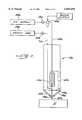
- FIG. 1is a schematic representation of a plasma torch which embodies the features of the present invention
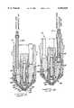
- FIG. 2is a more detailed end view of the torch shown in FIG. 1 and taken substantially along the line 2--2 of FIG. 1;
- FIGS. 3, 4, 5 and 6are sectional views of the torch taken respectively along the lines 3--3; 4--4; 5--5; and 6--6 of FIG. 2; and
- FIG. 7is a schematic representation of a second embodiment of a torch in accordance with the present invention.
- a plasma torchwhich embodies the features of the present invention is indicated generally at 10 in FIGS. 1-6, and the torch includes a body 12 having a central bore 13 which defines a longitudinal axis.
- An electrode 14is mounted in the central bore of the body 12 so as to extend along the longitudinal axis and define a front discharge end 16.
- the electrode 14is of cup shape so as to define a tubular rear end portion 17, and it is typically made of copper or a copper alloy with a silver/hafnium insert.
- the electrode 14is mounted in the bore 13 of the body 12 by a structure which includes a gas baffle 18 which surrounds the forward end portion of the electrode and which defines a depending sleeve 19 which coaxially surrounds the lower end of the electrode.
- the depending sleeve 19includes tangentially directed openings in the wall thereof, to impart a swirling motion to a gas passing therethrough, and as further described below.
- the gas baffle 18is retained by an outer sleeve 21 which also coaxially engages the mid-portion of the electrode 14. The outer sleeve 21 in turn is received in the central bore 13 of the body 12 of the torch.
- the rear end portion 17 of the electrode 14is threadedly connected to a tubular member 22, which coaxially supports a water baffle tube 24 which extends into the tubular rear portion of the electrode.
- the member 22includes a passage 25 which communicates with a water delivery line 26, and the passage 25 also communicates with the internal bore of the water baffle tube 24.
- the member 22also includes radial bores 28, which communicate via a second passage 29 in the member 22 with a water outlet line 30, for the purposes described below.
- a nozzle 32is coaxially mounted to the lower end of the gas baffle 18, and the nozzle 32 includes a frusto-conical front wall which defines a plasma cavity 33 immediately below the discharge end 16 of the electrode and which terminates with a bore 34 which is coaxial with the longitudinal axis.
- a shield 36is positioned in front of the nozzle 32, and the shield 36 comprises a nozzle retainer 38 and a shield cup 39.
- the nozzle retainer 38engages the front extremity of the nozzle 32, and defines a frusto-conical chamber 41 between the front wall of the nozzle 32 and the inner wall of the retainer 38.
- the shield cup 39overlies the nozzle retainer 38 in spaced relation, and the shield cup 39 includes a bore 42 which is coaxially aligned forwardly of the bore 34 of the nozzle.
- An annular passage 44is thereby defined between the outside of the retainer 38 and the inside of the shield cup 39, and the passage 44 terminates in an annular gas orifice 45 which coaxially surrounds the bore 34 of the nozzle.
- An insulator ring 46is disposed in the annular passage 44, and the passage 44 can be configured to impart a swirling motion to the shield gas flowing through the annular passage and to the annular gas orifice 45, as known in the art.
- the shield cup 39is supported by a shield cup retainer 48, which is in turn threadedly joined to a shield retainer sleeve 49.
- the retainer sleeve 49is threadedly joined to the torch body 12.
- the cooling water flow pathis best described with respect to FIG. 3.
- the water delivery line 26is connected to the inlet passage 25 in the member 22, which leads to the bore in the water baffle tube 24.
- the tube 24is of a diameter smaller than that of the bore in the rear portion 17 of the electrode 14, so as to provide a space for the water to flow back from the lower end of the tube 24, through the pair of radial bores 28 in the member 22, and to the second passage 29 in the member 22.
- the second passage 29communicates with the rearwardly extending water outlet line 30, and the line 30 is connected with a further delivery line 52 via a connector 53.
- the line 52leads to a passage 55 in the body 12 of the torch such that the water flows into the frusto-conical chamber 41 between the nozzle 32 and the nozzle retainer 38. From the chamber 41, the water flows out through a second passage 56 in the body and to a water outlet line 57.
- FIG. 4illustrates the internal structure for delivering a plasma start gas to the plasma cavity 33 in front of the discharge end 16 of the electrode 14.
- This delivery structureincludes a line 60 which is joined to the body 12 so as to communicate with a passage 61 in the body 12.
- the line 60mounts an internal one-way valve 62 in the form of a ball and spring which biases the ball upwardly toward a closed position against a seat formed in the interior of the line 60.
- the passage 61 in the torch bodyleads to an annular ring 66 formed in the bore 13 of the body.
- the annular ring 66communicates with a pathway (not shown) which extends through the wall of the outer sleeve 21 and along the outside of the gas baffle 18, and such that the gas passes through the tangentially directed openings in the depending sleeve 19 of the gas baffle 18 and so as to enter the plasma cavity 33 in a swirling fashion. From the cavity 33, the gas exits through the bore 34 of the nozzle 32.
- FIG. 5illustrates a shield gas delivery structure which leads to the annular passage 44 formed between the nozzle retainer 38 and the shield cup 39 as described above.
- This delivery structureincludes a line 68 leading to a passage 70 in the body 12 which communicates with the annular space between the inside wall of the shield retainer sleeve 49 and the outside wall of the nozzle retainer 38. From this annular space, the shield gas flows through a swirling structure (not shown) to the annular passage 44, and from the passage 44 the shield gas flows outwardly through the annular gas orifice 45 so as to coaxially surround the plasma stream exiting through the bore 34 of the nozzle 32.
- FIG. 6illustrates the plasma gas delivery structure, which includes a line 71 having a one-way valve 72 comprising a ball and spring, and which is similar to the valve 62 of the plasma start gas delivery structure shown in FIG. 4. From the line 71, the plasma gas is delivered through a passage 73 in the body 12 to the annular ring 66, from which the gas flows to the plasma cavity 33 in the manner described above with respect to FIG. 4.
- FIG. 1schematically illustrates a plasma arc torch 10 as described above and which is connected to its peripheral support equipment so as to be capable of operating either in a workpiece marking mode or in a workpiece cutting mode.
- the torch 10is positioned so that its forward end is spaced a short distance above a workpiece W and a power supply 75 is connected to the electrode 14 of the torch and the workpiece W in a conventional manner.
- the power supply 75is designed to selectively operate at either a max power setting, which typically delivers about 15 to 100 amps at 100% duty cycle, and a min power setting which typically delivers about 10 to 35 amps at 100% duty cycle.
- the max power settingis thus suitable for operation in the workpiece cutting mode
- the min settingis suitable for operation in the marking mode.
- the water delivery line 26 of the torchis connected to a cooling water source 77 via a valve 78, and the start gas delivery line 60 of the torch is connected to a source 79 of plasma start gas, such as air or nitrogen, via a valve 80.
- the start gascould also be argon.
- the plasma gas delivery line 71 of the torchis connected via a three-way valve 81, to either a plasma cutting gas supply 82, such as air, nitrogen or oxygen, or to a plasma marking gas supply 83, such as argon or a gas mixture containing a high percentage of argon.
- the shield gas delivery line 68 of the torchis connected to a shield gas supply 84 via a three-way valve 85.
- the shield gastypically comprises air, oxygen, nitrogen, CH 4 , or hydrogen
- the delivery line 68includes a bypass 86 which includes a water mist reservoir 88.
- the water reservoir 88has a flow control valve which permits a selected volume of water mist to be introduced into the gas stream.
- the valve 85can be moved between a closed position, or a first position delivering the shield gas directly to the torch, or a bypass position wherein the shield gas passes through the bypass 86 so that a water mist of a selected volume may be entrained in the gas stream.
- the power supply 75is set at the max setting, while the start gas is delivered to the start gas delivery line 60 and thus to the plasma cavity 33 between the discharge end 16 of the electrode 14 and the nozzle 32.
- the valve 80is closed and the valve 81 in the plasma gas delivery line is opened so as to permit the plasma cutting gas to enter the plasma gas delivery line 71.
- the torchis then operating in a mode suitable for cutting a metal workpiece.
- the power settingis shifted to the min setting, and the valve 81 is repositioned to direct the plasma marking gas into the plasma gas delivery line 71.
- the valve 85is repositioned to direct the shield gas through the bypass 86, so that water mist is entrained in the gas stream which is delivered to the shield gas delivery line 68.
- the torchis suitable for marking a workpiece.
- the presence of the water mist in the shield gashas been found to narrow the width of the line being etched in the workpiece, and to thereby provide improved definition.
- the water mistreduces the burn back of any primer on the metal, and it allows faster marking speeds.
- the bore 34 of the nozzle 32has a diameter of between about 0.018 to 0.043 inches, the power delivered to the electrode 14 is about 10 to 35 amps, and the plasma marking gas is 100% argon, which is delivered at a flow rate of 100 SCFH.
- the shield gasis 100% air, which is delivered at a flow rate of 60 SCFH, and the water mist is delivered to the flow at a maximum rate of about 0.5 GPM.
- FIG. 7schematically illustrates a torch 10a which embodies the invention, and which is configured to operate exclusively in the marking mode.
- the front wall of the nozzle 32ais frusto-conical and has a central bore 34a as described above with respect to the embodiment of FIGS. 1-6.
- the shieldcomprises a frusto-conical shield cup 39a which directly overlies the front wall of the nozzle 32a so as to define an annular passage 44a therebetween and which terminates in a annular gas orifice 45a which coaxially surrounds the bore 34a of the nozzle.
- the shield gas line 68a of the torchfirst comes in contact with the tubular rear portion of the electrode 14a, similar to the water flow path as described above with respect to FIG.
- the shield gas delivery line 68aincludes a shield gas source 84a, such as compressed air, and the line 68a includes a water mist reservoir 88a which includes a valve 85a for admitting a controlled amount of water mist which is entrained with the air.
- the plasma gas line 71ais connected to a source 83a of non-cutting marking gas, such as argon, via a valve 81a.
- the torch 10a of FIG. 7is operated at a power level of about 10 to 35 amps, while the argon is delivered to the plasma cavity below the discharge end of the electrode 14a. Also, the air/water mist moves serially into contact with the electrode 14a and then passes outwardly through the annular orifice 45a formed by the shield cup 39a. The air/water mist thus cools the electrode as well as the outer portion of the nozzle 32a, and the mist then flows to the surface of the workpiece W being marked, thereby providing the advantages noted above.
Landscapes
- Engineering & Computer Science (AREA)
- Physics & Mathematics (AREA)
- Plasma & Fusion (AREA)
- Mechanical Engineering (AREA)
- Spectroscopy & Molecular Physics (AREA)
- Plasma Technology (AREA)
- Arc Welding In General (AREA)
Abstract
Description
Claims (19)
Priority Applications (1)
| Application Number | Priority Date | Filing Date | Title |
|---|---|---|---|
| US09/082,241US6054669A (en) | 1998-05-20 | 1998-05-20 | Plasma marking torch and method of operating same |
Applications Claiming Priority (1)
| Application Number | Priority Date | Filing Date | Title |
|---|---|---|---|
| US09/082,241US6054669A (en) | 1998-05-20 | 1998-05-20 | Plasma marking torch and method of operating same |
Publications (1)
| Publication Number | Publication Date |
|---|---|
| US6054669Atrue US6054669A (en) | 2000-04-25 |
Family
ID=22169935
Family Applications (1)
| Application Number | Title | Priority Date | Filing Date |
|---|---|---|---|
| US09/082,241Expired - LifetimeUS6054669A (en) | 1998-05-20 | 1998-05-20 | Plasma marking torch and method of operating same |
Country Status (1)
| Country | Link |
|---|---|
| US (1) | US6054669A (en) |
Cited By (22)
| Publication number | Priority date | Publication date | Assignee | Title |
|---|---|---|---|---|
| US6236013B1 (en)* | 1998-10-22 | 2001-05-22 | La Soudure Autogene Francaise | Combined process and automatic installation for plasma-jet marking and cutting or welding, in particular of metals |
| US6326583B1 (en)* | 2000-03-31 | 2001-12-04 | Innerlogic, Inc. | Gas control system for a plasma arc torch |
| US6335505B2 (en)* | 2000-02-18 | 2002-01-01 | Safmatic | Control of the plasma cutting gas flow on the basis of the pressure of the pilot gas |
| US6346685B2 (en)* | 1998-03-06 | 2002-02-12 | The Esab Group, Inc. | Plasma arc torch |
| US6498317B2 (en) | 1998-10-23 | 2002-12-24 | Innerlogic, Inc. | Process for operating a plasma arc torch |
| EP1363480A1 (en)* | 2002-05-14 | 2003-11-19 | Tec.Mo S.r.l. | Abutment device for plasma torch |
| US20030213783A1 (en)* | 2002-04-19 | 2003-11-20 | Kinerson Kevin J. | Plasma arc torch cooling system |
| US6677551B2 (en) | 1998-10-23 | 2004-01-13 | Innerlogic, Inc. | Process for operating a plasma arc torch |
| US6777638B2 (en) | 2002-11-14 | 2004-08-17 | The Esab Group, Inc. | Plasma arc torch and method of operation for reduced erosion of electrode and nozzle |
| US6841754B2 (en) | 2001-03-09 | 2005-01-11 | Hypertherm, Inc. | Composite electrode for a plasma arc torch |
| US20060124606A1 (en)* | 2004-12-10 | 2006-06-15 | Doben Limited | Low impact spot welding cylinder using dual pistons |
| US20080093346A1 (en)* | 2006-10-18 | 2008-04-24 | Komatsu Ltd. | Plasma cutting device, plasma torch, and cooling device for plasma torch |
| US20110062119A1 (en)* | 2009-09-14 | 2011-03-17 | The Esab Group, Inc. | Underwater marking with a plasma arc torch |
| EP2316603A1 (en)* | 2009-10-30 | 2011-05-04 | Kjellberg Finsterwalde Plasma und Maschinen GmbH | Method for designing markings on surfaces of objects with a plasma burner |
| DE102011088433A1 (en) | 2010-12-13 | 2012-06-14 | The Esab Group, Inc. | Process and plasma arc torch system for marking and cutting workpieces with the same set of auxiliaries |
| US20140131311A1 (en)* | 2012-11-13 | 2014-05-15 | Samsung Display Co., Ltd | Thin film forming apparatus and thin film forming method using the same |
| US20140220784A1 (en)* | 2011-10-27 | 2014-08-07 | Panasonic Corporation | Plasma processing apparatus and plasma processing method |
| WO2016094302A1 (en)* | 2014-12-11 | 2016-06-16 | Hypertherm, Inc. | Water injection and venting of a plasma arc torch |
| US9949356B2 (en) | 2012-07-11 | 2018-04-17 | Lincoln Global, Inc. | Electrode for a plasma arc cutting torch |
| US20200009677A1 (en)* | 2015-10-06 | 2020-01-09 | Hypertherm, Inc. | Controlling and delivering gases in a plasma arc torch and related systems and methods |
| CN114535765A (en)* | 2022-01-25 | 2022-05-27 | 常州九圣焊割设备股份有限公司 | Plasma arc cutting torch |
| US20220346216A1 (en)* | 2019-09-12 | 2022-10-27 | Kjellberg-Stiftung | Wear Part for an Arc Torch and Plasma Torch, Arc Torch and Plasma Torch Comprising Same, Method for Plasma Cutting and Method for Producing an Electrode for an Arc Torch and Plasma Torch |
Citations (14)
| Publication number | Priority date | Publication date | Assignee | Title |
|---|---|---|---|---|
| US2906858A (en)* | 1957-10-10 | 1959-09-29 | Union Carbide Corp | Liquid vortex arc torch process |
| US3534388A (en)* | 1968-03-13 | 1970-10-13 | Hitachi Ltd | Plasma jet cutting process |
| US3567898A (en)* | 1968-07-01 | 1971-03-02 | Crucible Inc | Plasma arc cutting torch |
| US3619549A (en)* | 1970-06-19 | 1971-11-09 | Union Carbide Corp | Arc torch cutting process |
| US3833787A (en)* | 1972-06-12 | 1974-09-03 | Hypotherm Inc | Plasma jet cutting torch having reduced noise generating characteristics |
| US3934818A (en)* | 1972-12-20 | 1976-01-27 | Union Carbide Corporation | Method of oxy-fuel cutting |
| US4087670A (en)* | 1973-06-26 | 1978-05-02 | Lukens Steel Corp. | Process for suppression of noise and fumes generated by plasma-arc cutting operation |
| US4125754A (en)* | 1976-01-15 | 1978-11-14 | Rene Wasserman | Installation for surfacing using plasma-arc welding |
| US5045667A (en)* | 1990-06-06 | 1991-09-03 | Rockwell International Corporation | Manual keyhole plasma arc welding system |
| US5194715A (en)* | 1991-11-27 | 1993-03-16 | Esab Welding Products, Inc. | Plasma arc torch used in underwater cutting |
| US5393952A (en)* | 1991-02-28 | 1995-02-28 | Kabushiki Kaisha Komatsu Seisakusho | Plasma torch for cutting use with nozzle protection cap having annular secondary GPS passage and insulator disposed in the secondary gas passage |
| US5414237A (en)* | 1993-10-14 | 1995-05-09 | The Esab Group, Inc. | Plasma arc torch with integral gas exchange |
| US5773788A (en)* | 1996-09-03 | 1998-06-30 | Hypertherm, Inc. | Gas mixtures for plasma arc torch cutting and marking systems |
| US5893986A (en)* | 1997-04-11 | 1999-04-13 | The Esab Group, Inc. | Method of controlling a plasma arc cutting torch |
- 1998
- 1998-05-20USUS09/082,241patent/US6054669A/ennot_activeExpired - Lifetime
Patent Citations (14)
| Publication number | Priority date | Publication date | Assignee | Title |
|---|---|---|---|---|
| US2906858A (en)* | 1957-10-10 | 1959-09-29 | Union Carbide Corp | Liquid vortex arc torch process |
| US3534388A (en)* | 1968-03-13 | 1970-10-13 | Hitachi Ltd | Plasma jet cutting process |
| US3567898A (en)* | 1968-07-01 | 1971-03-02 | Crucible Inc | Plasma arc cutting torch |
| US3619549A (en)* | 1970-06-19 | 1971-11-09 | Union Carbide Corp | Arc torch cutting process |
| US3833787A (en)* | 1972-06-12 | 1974-09-03 | Hypotherm Inc | Plasma jet cutting torch having reduced noise generating characteristics |
| US3934818A (en)* | 1972-12-20 | 1976-01-27 | Union Carbide Corporation | Method of oxy-fuel cutting |
| US4087670A (en)* | 1973-06-26 | 1978-05-02 | Lukens Steel Corp. | Process for suppression of noise and fumes generated by plasma-arc cutting operation |
| US4125754A (en)* | 1976-01-15 | 1978-11-14 | Rene Wasserman | Installation for surfacing using plasma-arc welding |
| US5045667A (en)* | 1990-06-06 | 1991-09-03 | Rockwell International Corporation | Manual keyhole plasma arc welding system |
| US5393952A (en)* | 1991-02-28 | 1995-02-28 | Kabushiki Kaisha Komatsu Seisakusho | Plasma torch for cutting use with nozzle protection cap having annular secondary GPS passage and insulator disposed in the secondary gas passage |
| US5194715A (en)* | 1991-11-27 | 1993-03-16 | Esab Welding Products, Inc. | Plasma arc torch used in underwater cutting |
| US5414237A (en)* | 1993-10-14 | 1995-05-09 | The Esab Group, Inc. | Plasma arc torch with integral gas exchange |
| US5773788A (en)* | 1996-09-03 | 1998-06-30 | Hypertherm, Inc. | Gas mixtures for plasma arc torch cutting and marking systems |
| US5893986A (en)* | 1997-04-11 | 1999-04-13 | The Esab Group, Inc. | Method of controlling a plasma arc cutting torch |
Cited By (45)
| Publication number | Priority date | Publication date | Assignee | Title |
|---|---|---|---|---|
| US6346685B2 (en)* | 1998-03-06 | 2002-02-12 | The Esab Group, Inc. | Plasma arc torch |
| US6236013B1 (en)* | 1998-10-22 | 2001-05-22 | La Soudure Autogene Francaise | Combined process and automatic installation for plasma-jet marking and cutting or welding, in particular of metals |
| US6498317B2 (en) | 1998-10-23 | 2002-12-24 | Innerlogic, Inc. | Process for operating a plasma arc torch |
| US6677551B2 (en) | 1998-10-23 | 2004-01-13 | Innerlogic, Inc. | Process for operating a plasma arc torch |
| US6335505B2 (en)* | 2000-02-18 | 2002-01-01 | Safmatic | Control of the plasma cutting gas flow on the basis of the pressure of the pilot gas |
| US6326583B1 (en)* | 2000-03-31 | 2001-12-04 | Innerlogic, Inc. | Gas control system for a plasma arc torch |
| US20050067387A1 (en)* | 2001-03-09 | 2005-03-31 | Hypertherm, Inc. | Composite electrode for a plasma arc torch |
| USRE46925E1 (en) | 2001-03-09 | 2018-06-26 | Hypertherm, Inc. | Composite electrode for a plasma arc torch |
| US7659488B2 (en) | 2001-03-09 | 2010-02-09 | Hypertherm, Inc. | Composite electrode for a plasma arc torch |
| US20060289407A1 (en)* | 2001-03-09 | 2006-12-28 | Cook David J | Composite electrode for a plasma arc torch |
| US6841754B2 (en) | 2001-03-09 | 2005-01-11 | Hypertherm, Inc. | Composite electrode for a plasma arc torch |
| US20030213783A1 (en)* | 2002-04-19 | 2003-11-20 | Kinerson Kevin J. | Plasma arc torch cooling system |
| US20040079735A1 (en)* | 2002-04-19 | 2004-04-29 | Kinerson Kevin J. | Plasma arc torch head connections |
| US6946616B2 (en) | 2002-04-19 | 2005-09-20 | Thermal Dynamics Corporation | Plasma arc torch cooling system |
| US6919526B2 (en) | 2002-04-19 | 2005-07-19 | Thermal Dynamics Corporation | Plasma arc torch head connections |
| EP1363480A1 (en)* | 2002-05-14 | 2003-11-19 | Tec.Mo S.r.l. | Abutment device for plasma torch |
| US6777638B2 (en) | 2002-11-14 | 2004-08-17 | The Esab Group, Inc. | Plasma arc torch and method of operation for reduced erosion of electrode and nozzle |
| US20060124607A1 (en)* | 2004-12-10 | 2006-06-15 | Doben Limited | Low impact spot welding cylinder using single piston |
| US7714247B2 (en)* | 2004-12-10 | 2010-05-11 | Doben Limited | Low impact spot welding cylinder using single piston |
| US7718916B2 (en)* | 2004-12-10 | 2010-05-18 | Doben Limited | Low impact spot welding cylinder using dual pistons |
| US20100213246A1 (en)* | 2004-12-10 | 2010-08-26 | Doben Limited | Low impact spot welding cylinder using single or double piston |
| US8629369B2 (en) | 2004-12-10 | 2014-01-14 | Doben Limited | Low impact spot welding cylinder using single or double piston |
| US20060124606A1 (en)* | 2004-12-10 | 2006-06-15 | Doben Limited | Low impact spot welding cylinder using dual pistons |
| US20080093346A1 (en)* | 2006-10-18 | 2008-04-24 | Komatsu Ltd. | Plasma cutting device, plasma torch, and cooling device for plasma torch |
| US9024228B2 (en)* | 2006-10-18 | 2015-05-05 | Komatsu Ltd. | Plasma cutting device, plasma torch, and cooling device for plasma torch |
| US20110062119A1 (en)* | 2009-09-14 | 2011-03-17 | The Esab Group, Inc. | Underwater marking with a plasma arc torch |
| CN102574231A (en)* | 2009-09-14 | 2012-07-11 | 埃萨布集团公司 | Method of underwater marking on a workpiece with a plasma arc torch |
| EP2316603A1 (en)* | 2009-10-30 | 2011-05-04 | Kjellberg Finsterwalde Plasma und Maschinen GmbH | Method for designing markings on surfaces of objects with a plasma burner |
| DE102011088433A1 (en) | 2010-12-13 | 2012-06-14 | The Esab Group, Inc. | Process and plasma arc torch system for marking and cutting workpieces with the same set of auxiliaries |
| CN102554427A (en)* | 2010-12-13 | 2012-07-11 | 依赛彼集团公司 | Method and plasma arc torch system for marking and cutting workpieces with the same set of consumables |
| US10229814B2 (en) | 2011-10-27 | 2019-03-12 | Panasonic Intellectual Property Management Co., Ltd. | Plasma processing apparatus |
| US20140220784A1 (en)* | 2011-10-27 | 2014-08-07 | Panasonic Corporation | Plasma processing apparatus and plasma processing method |
| US10147585B2 (en)* | 2011-10-27 | 2018-12-04 | Panasonic Intellectual Property Management Co., Ltd. | Plasma processing apparatus |
| US9949356B2 (en) | 2012-07-11 | 2018-04-17 | Lincoln Global, Inc. | Electrode for a plasma arc cutting torch |
| US9034141B2 (en)* | 2012-11-13 | 2015-05-19 | Samsung Display Co., Ltd. | Thin film forming apparatus and thin film forming method using the same |
| US20140131311A1 (en)* | 2012-11-13 | 2014-05-15 | Samsung Display Co., Ltd | Thin film forming apparatus and thin film forming method using the same |
| CN107432079A (en)* | 2014-12-11 | 2017-12-01 | 海别得公司 | The water injection and exhaust of plasma torch |
| US10149376B2 (en) | 2014-12-11 | 2018-12-04 | Hypertherm, Inc. | Water injection and venting of a plasma arc torch |
| WO2016094302A1 (en)* | 2014-12-11 | 2016-06-16 | Hypertherm, Inc. | Water injection and venting of a plasma arc torch |
| US11212904B2 (en) | 2014-12-11 | 2021-12-28 | Hypertherm, Inc. | Water injection and venting of a plasma arc torch |
| US20200009677A1 (en)* | 2015-10-06 | 2020-01-09 | Hypertherm, Inc. | Controlling and delivering gases in a plasma arc torch and related systems and methods |
| US12325082B2 (en)* | 2015-10-06 | 2025-06-10 | Hypertherm, Inc. | Controlling and delivering gases in a plasma arc torch and related systems and methods |
| US20220346216A1 (en)* | 2019-09-12 | 2022-10-27 | Kjellberg-Stiftung | Wear Part for an Arc Torch and Plasma Torch, Arc Torch and Plasma Torch Comprising Same, Method for Plasma Cutting and Method for Producing an Electrode for an Arc Torch and Plasma Torch |
| CN114535765A (en)* | 2022-01-25 | 2022-05-27 | 常州九圣焊割设备股份有限公司 | Plasma arc cutting torch |
| CN114535765B (en)* | 2022-01-25 | 2024-05-17 | 常州九圣焊割设备股份有限公司 | Plasma arc cutting torch |
Similar Documents
| Publication | Publication Date | Title |
|---|---|---|
| US6054669A (en) | Plasma marking torch and method of operating same | |
| US11212904B2 (en) | Water injection and venting of a plasma arc torch | |
| KR930005953B1 (en) | How to start improved plasma arc torch | |
| US5660743A (en) | Plasma arc torch having water injection nozzle assembly | |
| US5013885A (en) | Plasma arc torch having extended nozzle of substantially hourglass | |
| CA2075316C (en) | Plasma arc torch having improved nozzle assembly | |
| US5414237A (en) | Plasma arc torch with integral gas exchange | |
| US8680425B2 (en) | Plasma arc torch having an electrode with internal passages | |
| CA2440113C (en) | Plasma arc torch and method of operation | |
| US5194715A (en) | Plasma arc torch used in underwater cutting | |
| US4581516A (en) | Plasma torch with a common gas source for the plasma and for the secondary gas flows | |
| US6096992A (en) | Low current water injection nozzle and associated method | |
| US6498316B1 (en) | Plasma torch and method for underwater cutting | |
| US6232574B1 (en) | Method and apparatus for improving plasma ARC consumable life |
Legal Events
| Date | Code | Title | Description |
|---|---|---|---|
| AS | Assignment | Owner name:ESAB GROUP, INC., THE, SOUTH CAROLINA Free format text:ASSIGNMENT OF ASSIGNORS INTEREST;ASSIGNOR:WARREN, JOSEPH V., JR.;REEL/FRAME:009189/0338 Effective date:19980518 | |
| STCF | Information on status: patent grant | Free format text:PATENTED CASE | |
| RF | Reissue application filed | Effective date:20020312 | |
| FEPP | Fee payment procedure | Free format text:PAYOR NUMBER ASSIGNED (ORIGINAL EVENT CODE: ASPN); ENTITY STATUS OF PATENT OWNER: LARGE ENTITY | |
| FPAY | Fee payment | Year of fee payment:4 | |
| FPAY | Fee payment | Year of fee payment:8 | |
| REMI | Maintenance fee reminder mailed | ||
| FEPP | Fee payment procedure | Free format text:PAYOR NUMBER ASSIGNED (ORIGINAL EVENT CODE: ASPN); ENTITY STATUS OF PATENT OWNER: LARGE ENTITY Free format text:PAYER NUMBER DE-ASSIGNED (ORIGINAL EVENT CODE: RMPN); ENTITY STATUS OF PATENT OWNER: LARGE ENTITY | |
| FPAY | Fee payment | Year of fee payment:12 | |
| AS | Assignment | Owner name:DEUTSCHE BANK AG NEW YORK BRANCH, NEW YORK Free format text:US INTELLECTUAL PROPERTY SECURITY AGREEMENT SUPPLEMENT;ASSIGNORS:ALCOTEC WIRE CORPORATION;ALLOY RODS GLOBAL, INC.;ANDERSON GROUP INC.;AND OTHERS;REEL/FRAME:028225/0020 Effective date:20120430 | |
| AS | Assignment | Owner name:DISTRIBUTION MINING & EQUIPMENT COMPANY, LLC, DELAWARE Free format text:RELEASE BY SECURED PARTY;ASSIGNOR:DEUTSCHE BANK AG NEW YORK BRANCH;REEL/FRAME:035903/0051 Effective date:20150605 Owner name:ESAB AB, SWEDEN Free format text:RELEASE BY SECURED PARTY;ASSIGNOR:DEUTSCHE BANK AG NEW YORK BRANCH;REEL/FRAME:035903/0051 Effective date:20150605 Owner name:SHAWEBONE HOLDINGS INC., SOUTH CAROLINA Free format text:RELEASE BY SECURED PARTY;ASSIGNOR:DEUTSCHE BANK AG NEW YORK BRANCH;REEL/FRAME:035903/0051 Effective date:20150605 Owner name:ANDERSON GROUP INC., SOUTH CAROLINA Free format text:RELEASE BY SECURED PARTY;ASSIGNOR:DEUTSCHE BANK AG NEW YORK BRANCH;REEL/FRAME:035903/0051 Effective date:20150605 Owner name:COLFAX CORPORATION, MARYLAND Free format text:RELEASE BY SECURED PARTY;ASSIGNOR:DEUTSCHE BANK AG NEW YORK BRANCH;REEL/FRAME:035903/0051 Effective date:20150605 Owner name:THE ESAB GROUP INC., SOUTH CAROLINA Free format text:RELEASE BY SECURED PARTY;ASSIGNOR:DEUTSCHE BANK AG NEW YORK BRANCH;REEL/FRAME:035903/0051 Effective date:20150605 Owner name:VICTOR TECHNOLOGIES INTERNATIONAL, INC., MISSOURI Free format text:RELEASE BY SECURED PARTY;ASSIGNOR:DEUTSCHE BANK AG NEW YORK BRANCH;REEL/FRAME:035903/0051 Effective date:20150605 Owner name:DISTRIBUTION MINING & EQUIPMENT COMPANY, LLC, DELA Free format text:RELEASE BY SECURED PARTY;ASSIGNOR:DEUTSCHE BANK AG NEW YORK BRANCH;REEL/FRAME:035903/0051 Effective date:20150605 Owner name:EMSA HOLDINGS INC., SOUTH CAROLINA Free format text:RELEASE BY SECURED PARTY;ASSIGNOR:DEUTSCHE BANK AG NEW YORK BRANCH;REEL/FRAME:035903/0051 Effective date:20150605 Owner name:CLARUS FLUID INTELLIGENCE, LLC, WASHINGTON Free format text:RELEASE BY SECURED PARTY;ASSIGNOR:DEUTSCHE BANK AG NEW YORK BRANCH;REEL/FRAME:035903/0051 Effective date:20150605 Owner name:CONSTELLATION PUMPS CORPORATION, DELAWARE Free format text:RELEASE BY SECURED PARTY;ASSIGNOR:DEUTSCHE BANK AG NEW YORK BRANCH;REEL/FRAME:035903/0051 Effective date:20150605 Owner name:HOWDEN COMPRESSORS, INC., SOUTH CAROLINA Free format text:RELEASE BY SECURED PARTY;ASSIGNOR:DEUTSCHE BANK AG NEW YORK BRANCH;REEL/FRAME:035903/0051 Effective date:20150605 Owner name:TOTAL LUBRICATION MANAGEMENT COMPANY, TEXAS Free format text:RELEASE BY SECURED PARTY;ASSIGNOR:DEUTSCHE BANK AG NEW YORK BRANCH;REEL/FRAME:035903/0051 Effective date:20150605 Owner name:STOODY COMPANY, MISSOURI Free format text:RELEASE BY SECURED PARTY;ASSIGNOR:DEUTSCHE BANK AG NEW YORK BRANCH;REEL/FRAME:035903/0051 Effective date:20150605 Owner name:HOWDEN GROUP LIMITED, SCOTLAND Free format text:RELEASE BY SECURED PARTY;ASSIGNOR:DEUTSCHE BANK AG NEW YORK BRANCH;REEL/FRAME:035903/0051 Effective date:20150605 Owner name:ALCOTEC WIRE CORPORATION, MICHIGAN Free format text:RELEASE BY SECURED PARTY;ASSIGNOR:DEUTSCHE BANK AG NEW YORK BRANCH;REEL/FRAME:035903/0051 Effective date:20150605 Owner name:VICTOR EQUIPMENT COMPANY, MISSOURI Free format text:RELEASE BY SECURED PARTY;ASSIGNOR:DEUTSCHE BANK AG NEW YORK BRANCH;REEL/FRAME:035903/0051 Effective date:20150605 Owner name:IMO INDUSTRIES INC., DELAWARE Free format text:RELEASE BY SECURED PARTY;ASSIGNOR:DEUTSCHE BANK AG NEW YORK BRANCH;REEL/FRAME:035903/0051 Effective date:20150605 Owner name:HOWDEN NORTH AMERICA INC., SOUTH CAROLINA Free format text:RELEASE BY SECURED PARTY;ASSIGNOR:DEUTSCHE BANK AG NEW YORK BRANCH;REEL/FRAME:035903/0051 Effective date:20150605 Owner name:ALLOY RODS GLOBAL INC., DELAWARE Free format text:RELEASE BY SECURED PARTY;ASSIGNOR:DEUTSCHE BANK AG NEW YORK BRANCH;REEL/FRAME:035903/0051 Effective date:20150605 Owner name:HOWDEN AMERICAN FAN COMPANY, SOUTH CAROLINA Free format text:RELEASE BY SECURED PARTY;ASSIGNOR:DEUTSCHE BANK AG NEW YORK BRANCH;REEL/FRAME:035903/0051 Effective date:20150605 |