US6054103A - Mixing system for processes using supercritical fluids - Google Patents
Mixing system for processes using supercritical fluidsDownload PDFInfo
- Publication number
- US6054103A US6054103AUS08/882,707US88270797AUS6054103AUS 6054103 AUS6054103 AUS 6054103AUS 88270797 AUS88270797 AUS 88270797AUS 6054103 AUS6054103 AUS 6054103A
- Authority
- US
- United States
- Prior art keywords
- pressure vessel
- liner
- heat transfer
- agitator
- channels
- Prior art date
- Legal status (The legal status is an assumption and is not a legal conclusion. Google has not performed a legal analysis and makes no representation as to the accuracy of the status listed.)
- Expired - Lifetime
Links
Images


Classifications
- B—PERFORMING OPERATIONS; TRANSPORTING
- B01—PHYSICAL OR CHEMICAL PROCESSES OR APPARATUS IN GENERAL
- B01J—CHEMICAL OR PHYSICAL PROCESSES, e.g. CATALYSIS OR COLLOID CHEMISTRY; THEIR RELEVANT APPARATUS
- B01J19/00—Chemical, physical or physico-chemical processes in general; Their relevant apparatus
- B01J19/26—Nozzle-type reactors, i.e. the distribution of the initial reactants within the reactor is effected by their introduction or injection through nozzles
- B—PERFORMING OPERATIONS; TRANSPORTING
- B01—PHYSICAL OR CHEMICAL PROCESSES OR APPARATUS IN GENERAL
- B01F—MIXING, e.g. DISSOLVING, EMULSIFYING OR DISPERSING
- B01F27/00—Mixers with rotary stirring devices in fixed receptacles; Kneaders
- B01F27/80—Mixers with rotary stirring devices in fixed receptacles; Kneaders with stirrers rotating about a substantially vertical axis
- B01F27/92—Mixers with rotary stirring devices in fixed receptacles; Kneaders with stirrers rotating about a substantially vertical axis with helices or screws
- B01F27/921—Mixers with rotary stirring devices in fixed receptacles; Kneaders with stirrers rotating about a substantially vertical axis with helices or screws with helices centrally mounted in the receptacle
- B01F27/9213—Mixers with rotary stirring devices in fixed receptacles; Kneaders with stirrers rotating about a substantially vertical axis with helices or screws with helices centrally mounted in the receptacle the helices having a diameter only slightly less than the diameter of the receptacle
- B—PERFORMING OPERATIONS; TRANSPORTING
- B01—PHYSICAL OR CHEMICAL PROCESSES OR APPARATUS IN GENERAL
- B01F—MIXING, e.g. DISSOLVING, EMULSIFYING OR DISPERSING
- B01F35/00—Accessories for mixers; Auxiliary operations or auxiliary devices; Parts or details of general application
- B01F35/90—Heating or cooling systems
- B01F35/92—Heating or cooling systems for heating the outside of the receptacle, e.g. heated jackets or burners
- B—PERFORMING OPERATIONS; TRANSPORTING
- B01—PHYSICAL OR CHEMICAL PROCESSES OR APPARATUS IN GENERAL
- B01J—CHEMICAL OR PHYSICAL PROCESSES, e.g. CATALYSIS OR COLLOID CHEMISTRY; THEIR RELEVANT APPARATUS
- B01J19/00—Chemical, physical or physico-chemical processes in general; Their relevant apparatus
- B01J19/18—Stationary reactors having moving elements inside
- B01J19/20—Stationary reactors having moving elements inside in the form of helices, e.g. screw reactors
- B—PERFORMING OPERATIONS; TRANSPORTING
- B01—PHYSICAL OR CHEMICAL PROCESSES OR APPARATUS IN GENERAL
- B01J—CHEMICAL OR PHYSICAL PROCESSES, e.g. CATALYSIS OR COLLOID CHEMISTRY; THEIR RELEVANT APPARATUS
- B01J3/00—Processes of utilising sub-atmospheric or super-atmospheric pressure to effect chemical or physical change of matter; Apparatus therefor
- B01J3/008—Processes carried out under supercritical conditions
- F—MECHANICAL ENGINEERING; LIGHTING; HEATING; WEAPONS; BLASTING
- F28—HEAT EXCHANGE IN GENERAL
- F28D—HEAT-EXCHANGE APPARATUS, NOT PROVIDED FOR IN ANOTHER SUBCLASS, IN WHICH THE HEAT-EXCHANGE MEDIA DO NOT COME INTO DIRECT CONTACT
- F28D1/00—Heat-exchange apparatus having stationary conduit assemblies for one heat-exchange medium only, the media being in contact with different sides of the conduit wall, in which the other heat-exchange medium is a large body of fluid, e.g. domestic or motor car radiators
- F28D1/06—Heat-exchange apparatus having stationary conduit assemblies for one heat-exchange medium only, the media being in contact with different sides of the conduit wall, in which the other heat-exchange medium is a large body of fluid, e.g. domestic or motor car radiators with the heat-exchange conduits forming part of, or being attached to, the tank containing the body of fluid
- B—PERFORMING OPERATIONS; TRANSPORTING
- B01—PHYSICAL OR CHEMICAL PROCESSES OR APPARATUS IN GENERAL
- B01F—MIXING, e.g. DISSOLVING, EMULSIFYING OR DISPERSING
- B01F23/00—Mixing according to the phases to be mixed, e.g. dispersing or emulsifying
- B01F23/04—Specific aggregation state of one or more of the phases to be mixed
- B01F23/043—Mixing fluids or with fluids in a supercritical state, in supercritical conditions or variable density fluids
- B—PERFORMING OPERATIONS; TRANSPORTING
- B01—PHYSICAL OR CHEMICAL PROCESSES OR APPARATUS IN GENERAL
- B01F—MIXING, e.g. DISSOLVING, EMULSIFYING OR DISPERSING
- B01F27/00—Mixers with rotary stirring devices in fixed receptacles; Kneaders
- B01F27/05—Stirrers
- B01F27/11—Stirrers characterised by the configuration of the stirrers
- B01F27/114—Helically shaped stirrers, i.e. stirrers comprising a helically shaped band or helically shaped band sections
- B01F27/1145—Helically shaped stirrers, i.e. stirrers comprising a helically shaped band or helically shaped band sections ribbon shaped with an open space between the helical ribbon flight and the rotating axis
- B01F27/11451—Helically shaped stirrers, i.e. stirrers comprising a helically shaped band or helically shaped band sections ribbon shaped with an open space between the helical ribbon flight and the rotating axis forming open frameworks or cages
- B—PERFORMING OPERATIONS; TRANSPORTING
- B01—PHYSICAL OR CHEMICAL PROCESSES OR APPARATUS IN GENERAL
- B01F—MIXING, e.g. DISSOLVING, EMULSIFYING OR DISPERSING
- B01F35/00—Accessories for mixers; Auxiliary operations or auxiliary devices; Parts or details of general application
- B01F35/50—Mixing receptacles
- B01F35/53—Mixing receptacles characterised by the configuration of the interior, e.g. baffles for facilitating the mixing of components
- B01F35/531—Mixing receptacles characterised by the configuration of the interior, e.g. baffles for facilitating the mixing of components with baffles, plates or bars on the wall or the bottom
- B—PERFORMING OPERATIONS; TRANSPORTING
- B01—PHYSICAL OR CHEMICAL PROCESSES OR APPARATUS IN GENERAL
- B01J—CHEMICAL OR PHYSICAL PROCESSES, e.g. CATALYSIS OR COLLOID CHEMISTRY; THEIR RELEVANT APPARATUS
- B01J2219/00—Chemical, physical or physico-chemical processes in general; Their relevant apparatus
- B01J2219/00002—Chemical plants
- B01J2219/00027—Process aspects
- B01J2219/00029—Batch processes
- B—PERFORMING OPERATIONS; TRANSPORTING
- B01—PHYSICAL OR CHEMICAL PROCESSES OR APPARATUS IN GENERAL
- B01J—CHEMICAL OR PHYSICAL PROCESSES, e.g. CATALYSIS OR COLLOID CHEMISTRY; THEIR RELEVANT APPARATUS
- B01J2219/00—Chemical, physical or physico-chemical processes in general; Their relevant apparatus
- B01J2219/00049—Controlling or regulating processes
- B01J2219/00051—Controlling the temperature
- B01J2219/00054—Controlling or regulating the heat exchange system
- B01J2219/00056—Controlling or regulating the heat exchange system involving measured parameters
- B01J2219/00069—Flow rate measurement
- B—PERFORMING OPERATIONS; TRANSPORTING
- B01—PHYSICAL OR CHEMICAL PROCESSES OR APPARATUS IN GENERAL
- B01J—CHEMICAL OR PHYSICAL PROCESSES, e.g. CATALYSIS OR COLLOID CHEMISTRY; THEIR RELEVANT APPARATUS
- B01J2219/00—Chemical, physical or physico-chemical processes in general; Their relevant apparatus
- B01J2219/00049—Controlling or regulating processes
- B01J2219/00051—Controlling the temperature
- B01J2219/00074—Controlling the temperature by indirect heating or cooling employing heat exchange fluids
- B01J2219/00076—Controlling the temperature by indirect heating or cooling employing heat exchange fluids with heat exchange elements inside the reactor
- B01J2219/00083—Coils
- B—PERFORMING OPERATIONS; TRANSPORTING
- B01—PHYSICAL OR CHEMICAL PROCESSES OR APPARATUS IN GENERAL
- B01J—CHEMICAL OR PHYSICAL PROCESSES, e.g. CATALYSIS OR COLLOID CHEMISTRY; THEIR RELEVANT APPARATUS
- B01J2219/00—Chemical, physical or physico-chemical processes in general; Their relevant apparatus
- B01J2219/00049—Controlling or regulating processes
- B01J2219/00051—Controlling the temperature
- B01J2219/00074—Controlling the temperature by indirect heating or cooling employing heat exchange fluids
- B01J2219/00087—Controlling the temperature by indirect heating or cooling employing heat exchange fluids with heat exchange elements outside the reactor
- B01J2219/0009—Coils
- B—PERFORMING OPERATIONS; TRANSPORTING
- B01—PHYSICAL OR CHEMICAL PROCESSES OR APPARATUS IN GENERAL
- B01J—CHEMICAL OR PHYSICAL PROCESSES, e.g. CATALYSIS OR COLLOID CHEMISTRY; THEIR RELEVANT APPARATUS
- B01J2219/00—Chemical, physical or physico-chemical processes in general; Their relevant apparatus
- B01J2219/00049—Controlling or regulating processes
- B01J2219/00051—Controlling the temperature
- B01J2219/00132—Controlling the temperature using electric heating or cooling elements
- B01J2219/00135—Electric resistance heaters
- B—PERFORMING OPERATIONS; TRANSPORTING
- B01—PHYSICAL OR CHEMICAL PROCESSES OR APPARATUS IN GENERAL
- B01J—CHEMICAL OR PHYSICAL PROCESSES, e.g. CATALYSIS OR COLLOID CHEMISTRY; THEIR RELEVANT APPARATUS
- B01J2219/00—Chemical, physical or physico-chemical processes in general; Their relevant apparatus
- B01J2219/00049—Controlling or regulating processes
- B01J2219/00162—Controlling or regulating processes controlling the pressure
- Y—GENERAL TAGGING OF NEW TECHNOLOGICAL DEVELOPMENTS; GENERAL TAGGING OF CROSS-SECTIONAL TECHNOLOGIES SPANNING OVER SEVERAL SECTIONS OF THE IPC; TECHNICAL SUBJECTS COVERED BY FORMER USPC CROSS-REFERENCE ART COLLECTIONS [XRACs] AND DIGESTS
- Y02—TECHNOLOGIES OR APPLICATIONS FOR MITIGATION OR ADAPTATION AGAINST CLIMATE CHANGE
- Y02P—CLIMATE CHANGE MITIGATION TECHNOLOGIES IN THE PRODUCTION OR PROCESSING OF GOODS
- Y02P20/00—Technologies relating to chemical industry
- Y02P20/50—Improvements relating to the production of bulk chemicals
- Y02P20/54—Improvements relating to the production of bulk chemicals using solvents, e.g. supercritical solvents or ionic liquids
Definitions
- the inventionrelates generally to apparatus for carrying out a process that uses supercritical fluids, such as, for example, a process for preparing coating materials as described in U.S. Pat. No. 5,399,597 and co-pending U.S. patent application Ser. No. 08/438,681 entitled "CONTROL SYSTEM FOR PROCESSES USING SUPERCRITICAL FLUID", the entire disclosures of which are both fully incorporated herein by reference. More specifically, the invention relates to improvements and alternative embodiments of the mixing system including the pressure vessel and agitator that are part of the overall system described in the aforementioned disclosures.
- Temperature control within the pressure vesselis an important part of the overall reaction process. It is especially important to provide a heat transfer system that can rapidly control changes of the reaction mixture within the pressure vessel. Although conventional heat/cool jackets can be used, as described in the referenced disclosures, some reaction processes may require a higher degree of control of temperature within the pressure vessel. This is particularly so for effecting and/or controlling rapid changes in temperature and pressure within the pressure vessel.
- the agitatoris also an important element of the overall system.
- the agitatornot only is used for mixing the batch ingredients during the reaction process in the pressure vessel, but is also used for delivery or transfer of the finished reaction to the receiver vessel.
- Typical reaction processescan involve high viscosity slurries within the pressure vessel which conventional agitators may be inadequate to either mix or assist in the transfer of the finished reaction to the receiver.
- apparatus for a process using supercritical process mediacomprising a pressure vessel including an agitator for mixing a batch of materials therein; a source of process media supplied to the pressure vessel; heat transfer means for maintaining the process media in the pressure vessel in a supercritical state; and delivery means for introducing into the pressure vessel batch materials that are mixed in the presence of the process media in a supercritical state to produce a reaction mixture based on a selectable reaction process;
- the heat transfer meanscomprising a liner that generally conforms to an interior surface geometry of the pressure vessel, with the liner comprising a high thermal conductivity material; the liner comprising an interior heat transfer surface in thermal exchange with the reaction mixture, and a plurality of fluid channels; heat transfer fluid that circulates through the channels and in thermal exchange with the heat transfer surface; and heat transfer fluid supply means exterior the pressure vessel for circulating the heat transfer fluid through the channels.
- the inventionalso contemplates in another embodiment a mixing vessel for a process using supercritical process media, the vessel comprising an agitator for mixing a batch of materials and a process media in a supercritical state in the vessel to produce a reaction mixture based on a selectable reaction process; and heat transfer means for controlling temperature of the reaction mixture, the heat transfer means comprising a liner that generally conforms to an interior surface geometry of the vessel, with the liner comprising a high thermal conductivity material; the liner comprising an interior heat transfer surface in thermal exchange with the reaction mixture, and a plurality of fluid channels; heat transfer fluid that circulates through the channels and in thermal exchange with the heat transfer surface; and heat transfer fluid supply means exterior the pressure vessel for circulating the heat transfer fluid through the channels.
- the inventionalso contemplates an agitator for reaction processes using supercritical process media, comprising: a drive shaft, impeller blades in the form of a double helix and which extend longitudinally about the drive shaft; and at least one radial impeller blade disposed near the periphery of the double helix and that extends longitudinally along the drive shaft.
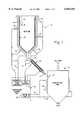
- FIG. 1is a simplified schematic representation of a pressure vessel (and receiver vessel) shown in partial cross-section in accordance with the invention
- FIG. 2is a more detailed illustration in partial cross-section of the pressure vessel in FIG. 1;
- FIG. 3illustrates a typical interconnection arrangement for the supply of heat transfer fluid to the pressure vessel of FIG. 1;
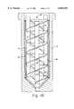
- FIGS. 4A and 4Billustrate an agitator in accordance with the invention, with FIG. 4B showing the agitator in a position rotated 90 degrees from the position of FIG. 4A.
- FIG. 1there is illustrated in elevation an embodiment of a pressure vessel 10 in accordance with the present invention. Many of the details concerning the operation and control of the overall system are provided in the referenced disclosures, and reference can be made thereto for further explanation of the reaction processes and controls.
- the present inventionis directed primarily to the pressure vessel 10 and to the agitator (not shown in FIG. 1) that is disposed within the pressure vessel 10.
- the pressure vessel 10is connected to the receiver vessel 12 via a transfer piping arrangement 14.
- a flush valve assembly 16is used to control transfer of material within the pressure vessel 10 through the piping 14 to the receiver vessel 12. Near the receiver vessel 12 the transfer piping 14 opens to an orifice 18 which further opens to the receiver vessel 12 via a tangential opening 20 in the receiver vessel wall.
- the fluid connection between the pressure vessel 10 and the receiver vessel 12can be realized as described in the referenced disclosures, for example, or alternatively the improved flush valve, orifice and tangential opening in the receiver vessel 12 as described in my co-pending U.S. patent application, Ser. No. 08/882,118 filed on Jun. 25, 1997 and entitled “DELIVERY SYSTEM FOR PROCESSES USING SUPERCRITICAL FLUIDS", the entire disclosure of which is fully incorporated herein by reference.
- the transfer piping 14can be equipped with band heaters 22 to prevent icing and coalescing of the material as it flows to the receiver vessel due to substantial temperature changes caused by the pressure drop from the pressure vessel 10 (for example, at 3000 psi) to the receiver vessel 12 (for example, at 300 psi).
- the band heatersare controlled via a temperature control unit 24 as will be described in greater detail hereinafter.
- the receiver vessel 12is preferably provided with an external heat/cool jacket 26 also controlled by the temperature control unit 24.
- the heat transfer fluid that flows through the receiver jacket 26may be brine or therminol D12, for example, forced through the jacket 26 via piping 28 by suitable pumps 30 that are part of the temperature control unit 24.
- Heating and/or cooling elementscan be provided with the temperature control unit 24 to adjust the temperature of the brine based on the required temperature within the receiver vessel 12.
- Conventional temperature sensorssuch as thermocouples can be used to monitor the temperature within the receiver vessel.
- the temperature control unit 24can also be provided with a conventional band heater control circuit 32 if required.
- the pressure vessel 10includes an inner liner 40 (in FIG. 1 the agitator is omitted for clarity).
- the liner 40(or alternatively the inner surface 42 of the vessel wall 44) has a number of fluid channels 46 or conduits formed therein. In the drawings, the relative size of the channels is somewhat exaggerated for clarity and ease of illustration.
- a heat transfer fluidis pumped through the channels 46 to control the temperature inside the pressure vessel 10.
- the liner 40is made of a material with a very high heat transfer coefficient.
- the liner 40is made of nickel. Alternative materials include aluminum, beryllium, cadmium, chromium and copper to name just a few examples.
- Alloyssuch as for example alloy cast irons, can alternatively be used.
- the metal or material selected for the liner 40will be determined in part by the choice of heat transfer fluid (in this example, therminol).
- the liner 40should also be durable and resistant to the materials that are introduced into the pressure vessel 10.
- a number of inlet ports 48 and outlet ports 50are provided. These ports are in fluid communication with the channels 46 and are used to supply and return the heat transfer fluid (represented by the directional flow arrows 52) through suitable piping from and to the temperature control unit 24.
- the temperature control unit 24will control the temperature of the heat transfer fluid as instructed by the main system controller as described in the referenced disclosures.
- the temperature control unitcan also be equipped with orifice flow meters and other monitoring apparatus to control flow rates and temperature of the heat transfer media through the liner 40 and the external jacket 26 as required.
- the heat transfer fluidis therminol D12 available from Dow Chemical or Monsanto.
- Other heat transfer fluids suitable for useinclude steam, brine, oil and glycerol to name just a few examples.
- the heat transfer fluid selected, along with the selected material for the liner 40,will be based in part on the degree of heat transfer capability required for a specific system. In many cases, it will be desirable to maximize heat transfer so as to provide a convenient means for accurate and fast control of the temperature of the reaction mixture within the pressure vessel 10.
- the pressure vessel 10in this case includes a generally cylindrical body wall 44 and a generally conically shaped bottom end 54.
- the conical portion 54can be welded or otherwise attached to the bottom of the cylindrical body 44.
- the conical end 54is truncated to provide an outlet opening 56, which can be provided with a flange to permit the flush valve assembly 16 (FIG. 1) to be mounted thereon.
- the upper end of the cylindrical body 44can also be equipped with a flange 58 which is used to support the pressure vessel 10 on a support structure (shown in phantom in FIG. 2). Although omitted from the drawings for clarity, the support structure also supports the drive motor for the agitator which is suspended within the pressure vessel 10, as will be described hereinafter.
- the liner 40is attached to the interior surface 42 of the pressure vessel 10 by any convenient means.
- the liner 40is welded to the pressure vessel wall 44, as at upper weld joint 60.
- the vessel 10is generally a two piece unit, so too the liner 40 includes a generally cylindrical 40 a and a conical lower portion 40b (alternatively, the liner could be made as a single integral piece, for example).
- the liner 40preferably is relatively thin to provide maximum heat transfer from the heat transfer fluid flowing through the channels 46 to the reaction mixture inside the vessel 10. In general, the heat transfer capability of the liner 40 decreases with increasing thickness of the liner 40.
- the liner 40must be thick enough, however, to withstand the pressure of the fluid therein, as well as to avoid rupturing should the agitator (within the pressure vessel 10) come into contact therewith.
- a liner 40 of thickness on the order of 0.2 to 1.4 incheshas been found suitable for the present invention, but these values are exemplary only and not limiting as to the scope of the invention. Heat transfer rates on the order of 0.75 to 2.5 million BTU/hr can be readily achieved, with again these values being exemplary and not limiting as to the scope of the invention.
- the liner 40is formed so as to closely conform with the interior geometry of the vessel 10, thus permitting the liner 40 to take up very little space within the tank, while at the same time being in intimate thermal contact with the reaction mixture as it circulates within the tank under the motive force of the agitator. It is important that the liner 40 be made of a sturdy material so that should the agitator deflect and hit the liner interior surface 62 the liner 40 will not rupture. Nickel is thus a preferred, though not exclusive material, for making the liner 40 due to its high heat conductivity and good strength. Note that preferably the cylindrical portion 40a and the conical portion 40b of the liner 40 are both provided with the channels 46, thus permitting excellent heat transfer and temperature control along the entire length of the pressure vessel 10.
- the bottom of the liner cylindrical portion 40a and the top of the conical liner portion 40bare attached to the vessel wall 44 by any convenient means.
- a single lower weld joint 64serves this purpose.
- the juncture or knuckle 66 of the cylindrical liner portion 40a and the conical portion 40b at the lower weld joint 64is provided with a reinforced raised inner surface 68.
- This reinforced areais referred to herein as a sacrificial deflection plate. It will be noted that within the area of the sacrificial plate 68 there are no channels 46 for the heat transfer fluid. Although a small amount of temperature control is lost or sacrificed in this region, the region is quite small. But, the reinforced knuckle 66 provides a strengthened area that can absorb impact of the agitator should the agitator be deflected against the wall of the liner 40. This further reduces the chance that the liner 40 could rupture, thereby releasing therminol or other heat transfer fluid into the reaction mixture, or even allowing material from the pressure vessel to back flow to the temperature control unit 24 pumps.
- the channels 46are formed as grooves in the outer surface of the liner 40.
- the channels 46can all be interconnected as a single continuous channel if so required, or the channels can be grouped and isolated, for example along the longitudinal vertical axis of the vessel 10, to provide zonal temperature control, if so required.
- the channels 46can also be isolated in groups, but then selectively interconnected by a series of hoses or piping on the exterior of the pressure vessel 10 (See FIG. 3).
- the channels in the conical portion 40bcan be connected to the channels in the cylindrical portion of the liner by exterior tubing or pipes.
- each zonecan be separately fed from the temperature control unit 24.
- each portcan be realized in the form of a tube or pipe that extends through the wall 44 of the pressure vessel 10 and opens to its respective channel 46.
- the number of ports utilizedwill depend on the extent of temperature control required along the length of the pressure vessel 10. Longer tanks may cause significant temperature variations along the length of the tank during a reaction process.
- FIG. 3A typical interconnection scheme is illustrated in FIG. 3. In this illustration, the connections to the temperature control unit 24 are omitted for clarity.
- a number of the ports 48, 50are interconnected by hoses 70 to provide zonal temperature control.
- the lower hose 70is used to interconnect the channels in the conical portion 40b with the channels in the lower end of the cylindrical portion 40a.
- the ports that are not shown as being interconnectedare connected by suitable hoses or piping to the inlets and outlets of the temperature control unit 24 pumps.
- various pressure and temperature sensorscan be provided at the various ports for providing control feedback signals to the temperature control unit and main control system.
- the heat transfer fluidbe pumped through the liner 40 in the form of a turbulent non-laminar flow.
- Flow meters and pressure and temperature sensorscan be used to monitor pressure drop and fluid flow rates through the various zones to assure turbulent flow.
- Baffles and other structurescan be provided as required to enhance a turbulent flow through the liner 40.
- an agitator 80is provided within the pressure vessel 10.
- FIG. 4Bshows the agitator rotated ninety degrees from the position shown in FIG. 4A.
- the agitator 80in this case is suspended from a support structure above the vessel 10 that includes the drive motor for the agitator 80 (not shown).
- the agitator 80is generally in the form of two elongated and intertwined serpentine blades 82 that form a double helix configuration.
- Each helical blade 82is supported on a main shaft 84 by a number of support arms 86 which in this case are generally evenly spaced along the longitudinal axis of the shaft 84.
- the reaction mixture within the vessel 10can be rather high in viscosity.
- the agitator 80is used for mixing and dispersion, and therefore preferably the agitator is designed to significantly work the reaction mixture to circulate it within the vessel. In some applications it will be useful to have a reversible drive motor, such as a DC variable motor available from Siemans.
- the agitator 80thus will tend to contribute a significant temperature increase to the mixture in the form of work performed in circulating the mixture throughout vessel 10.
- the double helix and fairly low flight angle of the blades 82produce a high work output from the agitator 80 to produce these effects.
- the main shaft 84is preferably made of a very hard non-deflecting material such as 316 stainless steel, as are the support arms 86 and blades 82.
- the exposed surfaces of the agitator 80can be Stellited if required for added stiffness and hardness, as well as electropolished.
- the outer sweep diameter of the blades 82is selected to be slightly less than the inner diameter of the liner 40. In this way, the circulating mixture is exposed to a large thermal transfer surface of the liner 40 for excellent temperature control of the reaction mixture.
- the agitator 80is suspended from the top of the vessel 10 (such as from a journal bearing coupled to the drive motor, not shown), and that there is no lower support bearing or other structure at the lower end of the agitator 80. Due to the potentially high viscosity of the reaction mixture, as well as the possible high rotation speeds of the agitator, the agitator 80 may be subject to small deflections, and these deflections will be most often extreme at the lower end of the agitator 80. Thus, as is apparent from FIG. 4B, the sacrificial deflection plate 68 described herein above absorbs the impacts of the agitator 80 to prevent a rupture of the liner 40.
- the agitator 80includes a pair of diametric opposed radial blades 88.
- the radial blades 88are, in this case, located towards the periphery of the agitator double helix, and extend along and generally parallel to the length of the main shaft 84.
- the bladesare formed as a helix to impart both a vertical pumping action (down or up depending on the direction of rotation of the agitator 80) as well as a radial motion so as to circulate the mixture towards the nickel liner 40.
- the radial blades 88operate to impart a circular motion to the reaction mixture as the agitator 80 rotates, further increasing the energy put into the mixture by operation of the agitator 80.
- the radial blades 88may be supported by the support arms 86 and or the double helix blades 82. This tends to maximize dispersion along the liner wall and produces wall shear to facilitate the mixing process and heat transfer.
- the blades 80are individually forged and then welded to the support arms, so that each helix is made up of a number of separate blade pieces.
Landscapes
- Chemical & Material Sciences (AREA)
- Chemical Kinetics & Catalysis (AREA)
- Organic Chemistry (AREA)
- Engineering & Computer Science (AREA)
- Physics & Mathematics (AREA)
- Thermal Sciences (AREA)
- Mechanical Engineering (AREA)
- General Engineering & Computer Science (AREA)
- Mixers Of The Rotary Stirring Type (AREA)
- Accessories For Mixers (AREA)
- Physical Or Chemical Processes And Apparatus (AREA)
Abstract
Description
Claims (19)
Priority Applications (1)
| Application Number | Priority Date | Filing Date | Title |
|---|---|---|---|
| US08/882,707US6054103A (en) | 1997-06-25 | 1997-06-25 | Mixing system for processes using supercritical fluids |
Applications Claiming Priority (1)
| Application Number | Priority Date | Filing Date | Title |
|---|---|---|---|
| US08/882,707US6054103A (en) | 1997-06-25 | 1997-06-25 | Mixing system for processes using supercritical fluids |
Publications (1)
| Publication Number | Publication Date |
|---|---|
| US6054103Atrue US6054103A (en) | 2000-04-25 |
Family
ID=25381167
Family Applications (1)
| Application Number | Title | Priority Date | Filing Date |
|---|---|---|---|
| US08/882,707Expired - LifetimeUS6054103A (en) | 1997-06-25 | 1997-06-25 | Mixing system for processes using supercritical fluids |
Country Status (1)
| Country | Link |
|---|---|
| US (1) | US6054103A (en) |
Cited By (18)
| Publication number | Priority date | Publication date | Assignee | Title |
|---|---|---|---|---|
| US6156079A (en)* | 1998-10-21 | 2000-12-05 | Ho; Henry | Window support member for a semiconductor processing system |
| US6506213B1 (en) | 2000-09-08 | 2003-01-14 | Ferro Corporation | Manufacturing orthopedic parts using supercritical fluid processing techniques |
| US6521258B1 (en) | 2000-09-08 | 2003-02-18 | Ferro Corporation | Polymer matrices prepared by supercritical fluid processing techniques |
| US6579532B1 (en) | 2000-09-08 | 2003-06-17 | Ferro Corporation | Orthopedic mixtures prepared by supercritical fluid processing techniques |
| WO2003041848A3 (en)* | 2001-11-12 | 2003-08-14 | Amersham Health As | Construction material for a pharmaceutical mixing apparatus |
| US20040002474A1 (en)* | 1999-10-07 | 2004-01-01 | Maxygen Inc. | IFN-alpha homologues |
| US20060210598A1 (en)* | 2002-07-06 | 2006-09-21 | Evans Douglas G | Resorbable structure for treating and healing of tissue defects |
| US20090152750A1 (en)* | 2007-12-12 | 2009-06-18 | Cesario Dos Santos | Vacuum Drug Pellet Molding |
| US20090275776A1 (en)* | 2005-07-12 | 2009-11-05 | Kabushiki Kaisha Kobe Seiko Sho(Kobe Steel, Ltd) | Process and equipment for the decomposition and recovery of isocyanate compounds |
| CN101234309B (en)* | 2007-11-16 | 2010-12-22 | 中国石油大学(北京) | Double helical ribbon multi-layer oar blade scraping cutter type stirrer |
| US8598092B2 (en) | 2005-02-02 | 2013-12-03 | Halliburton Energy Services, Inc. | Methods of preparing degradable materials and methods of use in subterranean formations |
| EP3088368A1 (en)* | 2015-04-29 | 2016-11-02 | SCW Systems B.V. | Apparatus for and method of processing a slurry containing organic components |
| US20170066157A1 (en)* | 2014-05-02 | 2017-03-09 | Construction Robotics, Llc | Mortar Delivery System |
| WO2018146483A1 (en)* | 2017-02-09 | 2018-08-16 | Phycofeeds Limited | Hydrothermal liquefaction reactor |
| US20180279645A1 (en)* | 2017-03-31 | 2018-10-04 | Ali Group S.R.L. - Carpigiani | Machine for liquid or semi-liquid food products |
| CN110102239A (en)* | 2019-05-20 | 2019-08-09 | 徐州工程学院 | A kind of reactor and its control method containing heating software |
| US10889067B1 (en)* | 2015-04-13 | 2021-01-12 | Lockheed Martin Corporation | Tension-wound solid state additive manufacturing |
| US20230201778A1 (en)* | 2020-04-20 | 2023-06-29 | Metso Outotec Finland Oy | Mixing arrangement, mixer settler unit and use |
Citations (32)
| Publication number | Priority date | Publication date | Assignee | Title |
|---|---|---|---|---|
| US313430A (en)* | 1885-03-03 | of cincinnati | ||
| US954511A (en)* | 1910-01-03 | 1910-04-12 | Stearns Roger Mfg Co | Pulp-agitator. |
| US1911608A (en)* | 1933-05-30 | Fressttbe vessel lining | ||
| US2772860A (en)* | 1953-07-28 | 1956-12-04 | Shell Dev | Vessel with continuous helical liner |
| US2939770A (en)* | 1954-08-07 | 1960-06-07 | Noblee & Thorl G M B H | Reaction column for the continuous treatment of liquids |
| US3078265A (en)* | 1957-09-12 | 1963-02-19 | Phillips Petroleum Co | Control of polymerization reactions |
| US3227526A (en)* | 1958-11-13 | 1966-01-04 | Phillips Petroleum Co | Reactor system |
| US3249342A (en)* | 1964-07-14 | 1966-05-03 | Laurits A Mikkelsen | Mixer |
| US3476522A (en)* | 1966-11-16 | 1969-11-04 | Crawford & Russell Inc | High viscosity reactors |
| US3803084A (en)* | 1968-03-23 | 1974-04-09 | Bayer Ag | Process for the production of high-polymer organo-siloxanes |
| US3877881A (en)* | 1968-10-08 | 1975-04-15 | Mitsubishi Heavy Ind Ltd | Reactors for highly viscous materials |
| US3926738A (en)* | 1972-05-10 | 1975-12-16 | Wilson John D | Method and apparatus for control of biochemical processes |
| US3981957A (en)* | 1975-08-06 | 1976-09-21 | Exxon Research And Engineering Company | Process for preparing finely divided polymers |
| US4012461A (en)* | 1975-08-06 | 1977-03-15 | Exxon Research And Engineering Company | Process for preparing polymer powders |
| US4022438A (en)* | 1974-05-13 | 1977-05-10 | Mitsubishi Kasei Kogyo Kabushiki Kaisha | Stirring apparatus |
| US4552724A (en)* | 1981-03-09 | 1985-11-12 | Shinko-Pfaudler Company, Ltd. | Reaction and heat exchanger apparatus |
| US4582731A (en)* | 1983-09-01 | 1986-04-15 | Battelle Memorial Institute | Supercritical fluid molecular spray film deposition and powder formation |
| US4734451A (en)* | 1983-09-01 | 1988-03-29 | Battelle Memorial Institute | Supercritical fluid molecular spray thin films and fine powders |
| US4734227A (en)* | 1983-09-01 | 1988-03-29 | Battelle Memorial Institute | Method of making supercritical fluid molecular spray films, powder and fibers |
| US4970093A (en)* | 1990-04-12 | 1990-11-13 | University Of Colorado Foundation | Chemical deposition methods using supercritical fluid solutions |
| US5009367A (en)* | 1989-03-22 | 1991-04-23 | Union Carbide Chemicals And Plastics Technology Corporation | Methods and apparatus for obtaining wider sprays when spraying liquids by airless techniques |
| US5027742A (en)* | 1987-12-21 | 1991-07-02 | Union Carbide Chemicals And Plastics Technology Corporation | Supercritical fluids as diluents in liquid spray application of coatings |
| US5152971A (en)* | 1989-05-19 | 1992-10-06 | Atochem | Production of high molecular weight, essentially uncrosslinked polychlorophosphazenes |
| US5171613A (en)* | 1990-09-21 | 1992-12-15 | Union Carbide Chemicals & Plastics Technology Corporation | Apparatus and methods for application of coatings with supercritical fluids as diluents by spraying from an orifice |
| US5182087A (en)* | 1990-04-04 | 1993-01-26 | Outokumpu Oy | Method for mixing two liquids or liquid and solid material together, and for simultaneously separating another liquid or solid from the liquid |
| US5248485A (en)* | 1990-04-04 | 1993-09-28 | Outokumpu Oy | Method for mixing liquid, solids and gas and for simultaneously separating gas or gas and solids from the liquid |
| US5290827A (en)* | 1991-03-27 | 1994-03-01 | University Of Delaware | Precipitation of homogeneous polymer mixtures from supercritical fluid solutions |
| WO1994009913A1 (en)* | 1992-11-02 | 1994-05-11 | Ferro Corporation | Method of preparing coating materials |
| US5380485A (en)* | 1989-08-28 | 1995-01-10 | Todoroki Sangyo Kabushiki Kaisha | Apparatus for conducting and controlling chemical reactions |
| US5407267A (en)* | 1992-12-30 | 1995-04-18 | Nordson Corporation | Method and apparatus for forming and dispensing coating material containing multiple components |
| US5667758A (en)* | 1993-12-27 | 1997-09-16 | Sumitomo Heavy Industries, Ltd. | Processing vessel |
| US5698163A (en)* | 1995-05-10 | 1997-12-16 | Ferro Corporation | Control system for processes using supercritical fluids |
- 1997
- 1997-06-25USUS08/882,707patent/US6054103A/ennot_activeExpired - Lifetime
Patent Citations (33)
| Publication number | Priority date | Publication date | Assignee | Title |
|---|---|---|---|---|
| US313430A (en)* | 1885-03-03 | of cincinnati | ||
| US1911608A (en)* | 1933-05-30 | Fressttbe vessel lining | ||
| US954511A (en)* | 1910-01-03 | 1910-04-12 | Stearns Roger Mfg Co | Pulp-agitator. |
| US2772860A (en)* | 1953-07-28 | 1956-12-04 | Shell Dev | Vessel with continuous helical liner |
| US2939770A (en)* | 1954-08-07 | 1960-06-07 | Noblee & Thorl G M B H | Reaction column for the continuous treatment of liquids |
| US3078265A (en)* | 1957-09-12 | 1963-02-19 | Phillips Petroleum Co | Control of polymerization reactions |
| US3227526A (en)* | 1958-11-13 | 1966-01-04 | Phillips Petroleum Co | Reactor system |
| US3249342A (en)* | 1964-07-14 | 1966-05-03 | Laurits A Mikkelsen | Mixer |
| US3476522A (en)* | 1966-11-16 | 1969-11-04 | Crawford & Russell Inc | High viscosity reactors |
| US3803084A (en)* | 1968-03-23 | 1974-04-09 | Bayer Ag | Process for the production of high-polymer organo-siloxanes |
| US3877881A (en)* | 1968-10-08 | 1975-04-15 | Mitsubishi Heavy Ind Ltd | Reactors for highly viscous materials |
| US3926738A (en)* | 1972-05-10 | 1975-12-16 | Wilson John D | Method and apparatus for control of biochemical processes |
| US4022438A (en)* | 1974-05-13 | 1977-05-10 | Mitsubishi Kasei Kogyo Kabushiki Kaisha | Stirring apparatus |
| US3981957A (en)* | 1975-08-06 | 1976-09-21 | Exxon Research And Engineering Company | Process for preparing finely divided polymers |
| US4012461A (en)* | 1975-08-06 | 1977-03-15 | Exxon Research And Engineering Company | Process for preparing polymer powders |
| US4552724A (en)* | 1981-03-09 | 1985-11-12 | Shinko-Pfaudler Company, Ltd. | Reaction and heat exchanger apparatus |
| US4582731A (en)* | 1983-09-01 | 1986-04-15 | Battelle Memorial Institute | Supercritical fluid molecular spray film deposition and powder formation |
| US4734451A (en)* | 1983-09-01 | 1988-03-29 | Battelle Memorial Institute | Supercritical fluid molecular spray thin films and fine powders |
| US4734227A (en)* | 1983-09-01 | 1988-03-29 | Battelle Memorial Institute | Method of making supercritical fluid molecular spray films, powder and fibers |
| US5027742A (en)* | 1987-12-21 | 1991-07-02 | Union Carbide Chemicals And Plastics Technology Corporation | Supercritical fluids as diluents in liquid spray application of coatings |
| US5009367A (en)* | 1989-03-22 | 1991-04-23 | Union Carbide Chemicals And Plastics Technology Corporation | Methods and apparatus for obtaining wider sprays when spraying liquids by airless techniques |
| US5152971A (en)* | 1989-05-19 | 1992-10-06 | Atochem | Production of high molecular weight, essentially uncrosslinked polychlorophosphazenes |
| US5380485A (en)* | 1989-08-28 | 1995-01-10 | Todoroki Sangyo Kabushiki Kaisha | Apparatus for conducting and controlling chemical reactions |
| US5248485A (en)* | 1990-04-04 | 1993-09-28 | Outokumpu Oy | Method for mixing liquid, solids and gas and for simultaneously separating gas or gas and solids from the liquid |
| US5182087A (en)* | 1990-04-04 | 1993-01-26 | Outokumpu Oy | Method for mixing two liquids or liquid and solid material together, and for simultaneously separating another liquid or solid from the liquid |
| US4970093A (en)* | 1990-04-12 | 1990-11-13 | University Of Colorado Foundation | Chemical deposition methods using supercritical fluid solutions |
| US5171613A (en)* | 1990-09-21 | 1992-12-15 | Union Carbide Chemicals & Plastics Technology Corporation | Apparatus and methods for application of coatings with supercritical fluids as diluents by spraying from an orifice |
| US5290827A (en)* | 1991-03-27 | 1994-03-01 | University Of Delaware | Precipitation of homogeneous polymer mixtures from supercritical fluid solutions |
| WO1994009913A1 (en)* | 1992-11-02 | 1994-05-11 | Ferro Corporation | Method of preparing coating materials |
| US5399597A (en)* | 1992-11-02 | 1995-03-21 | Ferro Corporation | Method of preparing coating materials |
| US5407267A (en)* | 1992-12-30 | 1995-04-18 | Nordson Corporation | Method and apparatus for forming and dispensing coating material containing multiple components |
| US5667758A (en)* | 1993-12-27 | 1997-09-16 | Sumitomo Heavy Industries, Ltd. | Processing vessel |
| US5698163A (en)* | 1995-05-10 | 1997-12-16 | Ferro Corporation | Control system for processes using supercritical fluids |
Non-Patent Citations (14)
| Title |
|---|
| G. A. M. Diepen et al., "The Solubility of Napththalene in Supercritical Ethylene," Dec. 1948, pp. 4085-4089. |
| G. A. M. Diepen et al., The Solubility of Napththalene in Supercritical Ethylene, Dec. 1948, pp. 4085 4089.* |
| Hongju Chang et al., "Solubilities of Methoxy-1-tetralone and Methyl Nitrobenzoate Isomers and Their Mixtures in Supercritical Carbon Dioxide," Journal of Chemical Engineering Data, vol. 30, No. 1, 1985, pp. 74-78. |
| Hongju Chang et al., Solubilities of Methoxy 1 tetralone and Methyl Nitrobenzoate Isomers and Their Mixtures in Supercritical Carbon Dioxide, Journal of Chemical Engineering Data, vol. 30, No. 1, 1985, pp. 74 78.* |
| Karen A. Larson et al., "Evaluation of Supercritical Fluid Extraction in the Pharmaceutical Industry," Biotechnology Progress, vol. 2, No. 2., Jun. 1986, pp. 73-82. |
| Karen A. Larson et al., Evaluation of Supercritical Fluid Extraction in the Pharmaceutical Industry, Biotechnology Progress, vol. 2, No. 2., Jun. 1986, pp. 73 82.* |
| Mark McHugh et al., "Solid Solubilities of Naphtalene and Biphenyl in Supercritical Carbon Dioxide,"Journal of Chemical Engineering Data, vol. 25, No. 4, 1980, pp. 326-329. |
| Mark McHugh et al., Solid Solubilities of Naphtalene and Biphenyl in Supercritical Carbon Dioxide, Journal of Chemical Engineering Data, vol. 25, No. 4, 1980, pp. 326 329.* |
| Ronald T. Kurnik et al., "Solubility of Solids in Supercritical Carbon Dioxide and Ethylene," Journal of Chemical and Engineering Data, vol. 26, No. 1, 1981, pp. 47-51. |
| Ronald T. Kurnik et al., Solubility of Solids in Supercritical Carbon Dioxide and Ethylene, Journal of Chemical and Engineering Data, vol. 26, No. 1, 1981, pp. 47 51.* |
| Walter Cobbs et al., "High Solids Coatings Above 80% By Volume," presented at the Water-Borne & Higher Solids Coatings Symposium, Mar. 10-12, 1980, New Orleans, LA, pp. 175-192. |
| Walter Cobbs et al., High Solids Coatings Above 80% By Volume, presented at the Water Borne & Higher Solids Coatings Symposium, Mar. 10 12, 1980, New Orleans, LA, pp. 175 192.* |
| Yu V. Tsekhanskaya et al., "Volume Changes In Naphthalene Solutions In Compressed Carbon Dioxide," Russian Journal of Physical Chemistry, vol. 40, No. 9, Sep. 1966, pp. 1152-1156. |
| Yu V. Tsekhanskaya et al., Volume Changes In Naphthalene Solutions In Compressed Carbon Dioxide, Russian Journal of Physical Chemistry, vol. 40, No. 9, Sep. 1966, pp. 1152 1156.* |
Cited By (29)
| Publication number | Priority date | Publication date | Assignee | Title |
|---|---|---|---|---|
| US6156079A (en)* | 1998-10-21 | 2000-12-05 | Ho; Henry | Window support member for a semiconductor processing system |
| US20040002474A1 (en)* | 1999-10-07 | 2004-01-01 | Maxygen Inc. | IFN-alpha homologues |
| US6506213B1 (en) | 2000-09-08 | 2003-01-14 | Ferro Corporation | Manufacturing orthopedic parts using supercritical fluid processing techniques |
| US6521258B1 (en) | 2000-09-08 | 2003-02-18 | Ferro Corporation | Polymer matrices prepared by supercritical fluid processing techniques |
| US6579532B1 (en) | 2000-09-08 | 2003-06-17 | Ferro Corporation | Orthopedic mixtures prepared by supercritical fluid processing techniques |
| WO2003041848A3 (en)* | 2001-11-12 | 2003-08-14 | Amersham Health As | Construction material for a pharmaceutical mixing apparatus |
| US20060210598A1 (en)* | 2002-07-06 | 2006-09-21 | Evans Douglas G | Resorbable structure for treating and healing of tissue defects |
| US8598092B2 (en) | 2005-02-02 | 2013-12-03 | Halliburton Energy Services, Inc. | Methods of preparing degradable materials and methods of use in subterranean formations |
| US20090275776A1 (en)* | 2005-07-12 | 2009-11-05 | Kabushiki Kaisha Kobe Seiko Sho(Kobe Steel, Ltd) | Process and equipment for the decomposition and recovery of isocyanate compounds |
| US20110190534A1 (en)* | 2005-07-12 | 2011-08-04 | Kabushiki Kaisha Kobe Seiko Sho (Kobe Steel, Ltd) | Method for decomposing and recovering isocyanate compound |
| US8038958B2 (en)* | 2005-07-12 | 2011-10-18 | Kobe Steel, Ltd. | Method for decomposing and recovering isocyanate compound |
| US8669394B2 (en) | 2005-07-12 | 2014-03-11 | Kobe Steel, Ltd. | Method for decomposing and recovering isocyanate compound |
| CN101234309B (en)* | 2007-11-16 | 2010-12-22 | 中国石油大学(北京) | Double helical ribbon multi-layer oar blade scraping cutter type stirrer |
| US20090152750A1 (en)* | 2007-12-12 | 2009-06-18 | Cesario Dos Santos | Vacuum Drug Pellet Molding |
| US10759087B2 (en)* | 2014-05-02 | 2020-09-01 | Construction Robotics, Llc | Mortar delivery system |
| US20170066157A1 (en)* | 2014-05-02 | 2017-03-09 | Construction Robotics, Llc | Mortar Delivery System |
| US10889067B1 (en)* | 2015-04-13 | 2021-01-12 | Lockheed Martin Corporation | Tension-wound solid state additive manufacturing |
| EP3088368A1 (en)* | 2015-04-29 | 2016-11-02 | SCW Systems B.V. | Apparatus for and method of processing a slurry containing organic components |
| EP3542895A1 (en)* | 2015-04-29 | 2019-09-25 | SCW Systems B.V. | Apparatus for and method of processing a slurry containing organic components |
| CN107531534A (en)* | 2015-04-29 | 2018-01-02 | Scw系统公司 | For handling the apparatus and method of the slurry containing organic component |
| RU2736538C2 (en)* | 2015-04-29 | 2020-11-17 | Скв Системс Б.В. | Apparatus and method of processing a suspension containing organic components |
| WO2016174163A1 (en)* | 2015-04-29 | 2016-11-03 | Scw Systems B.V. | Apparatus for and method of processing a slurry containing organic components |
| US11498861B2 (en) | 2015-04-29 | 2022-11-15 | Scw Systems B.V. | Apparatus for and method of processing a slurry containing organic components |
| WO2018146483A1 (en)* | 2017-02-09 | 2018-08-16 | Phycofeeds Limited | Hydrothermal liquefaction reactor |
| US20180279645A1 (en)* | 2017-03-31 | 2018-10-04 | Ali Group S.R.L. - Carpigiani | Machine for liquid or semi-liquid food products |
| CN108813085A (en)* | 2017-03-31 | 2018-11-16 | 艾力集团有限责任公司-卡皮贾尼 | For liquid or the machine of semi-liquid food products |
| US11140911B2 (en)* | 2017-03-31 | 2021-10-12 | Ali Group S.R.L.—Carpigiani | Machine for liquid or semi-liquid food products |
| CN110102239A (en)* | 2019-05-20 | 2019-08-09 | 徐州工程学院 | A kind of reactor and its control method containing heating software |
| US20230201778A1 (en)* | 2020-04-20 | 2023-06-29 | Metso Outotec Finland Oy | Mixing arrangement, mixer settler unit and use |
Similar Documents
| Publication | Publication Date | Title |
|---|---|---|
| US6054103A (en) | Mixing system for processes using supercritical fluids | |
| CN107456935B (en) | A kind of pneumatic glass lined stirring device | |
| EP3273174B1 (en) | Liquid heating device | |
| KR101531859B1 (en) | Agitator capable of heating and cooling liquid material agitated | |
| JP2011514837A (en) | Stirred tank reactor and method for carrying out a polymerization reaction using such a stirred tank reactor | |
| CN217189594U (en) | A PVDF polymerization kettle | |
| CN207385478U (en) | horizontal pressure-bearing solid phase reaction kettle | |
| CA1075227A (en) | Swept surface heat exchanger | |
| CN204193943U (en) | Temperature automatically controlled reactor | |
| CN114471411A (en) | Reation kettle is used in chemical product processing of high temperature accuse precision | |
| CN217248932U (en) | Chemical reaction kettle capable of efficiently stirring and cooling | |
| CN219150139U (en) | Chemical industry reation kettle that can cool off fast | |
| CN212142631U (en) | Reactor and reaction system for quantum dot synthesis | |
| CN214915999U (en) | Reaction kettle device heated through heat conduction oil | |
| CN211800809U (en) | Heating reaction kettle | |
| CN213885949U (en) | Mixing machine | |
| CN213913449U (en) | Mixing machine | |
| CN213854513U (en) | Thermal insulation processing kettle for fully-synthesized metal working fluid | |
| JP3880461B2 (en) | Multi-tube heat transfer stirrer | |
| CN211913751U (en) | High-temperature rapid heat dissipation reaction kettle | |
| CN210114984U (en) | Novel SNCR urea dissolving tank | |
| CN219682503U (en) | Stirring reaction kettle for chemical industry | |
| CN111437791A (en) | Reactor and reaction system for quantum dot synthesis | |
| CN110327826A (en) | A kind of polymer emulsified equipment of nanofiber production | |
| CN217697995U (en) | High viscous solution cooling device |
Legal Events
| Date | Code | Title | Description |
|---|---|---|---|
| AS | Assignment | Owner name:FERRO CORPORATION, OHIO Free format text:ASSIGNMENT OF ASSIGNORS INTEREST;ASSIGNOR:MANDEL, FREDERICK S.;REEL/FRAME:008668/0949 Effective date:19970620 | |
| STCF | Information on status: patent grant | Free format text:PATENTED CASE | |
| FEPP | Fee payment procedure | Free format text:PAYOR NUMBER ASSIGNED (ORIGINAL EVENT CODE: ASPN); ENTITY STATUS OF PATENT OWNER: LARGE ENTITY | |
| FPAY | Fee payment | Year of fee payment:4 | |
| AS | Assignment | Owner name:NATIONAL CITY BANK, AS ADMINISTRATIVE AGENT,OHIO Free format text:SECURITY AGREEMENT;ASSIGNOR:FERRO CORPORATION;REEL/FRAME:017527/0909 Effective date:20060419 Owner name:NATIONAL CITY BANK, AS ADMINISTRATIVE AGENT, OHIO Free format text:SECURITY AGREEMENT;ASSIGNOR:FERRO CORPORATION;REEL/FRAME:017527/0909 Effective date:20060419 | |
| AS | Assignment | Owner name:NATIONAL CITY BANK, AS COLLATERAL AGENT,OHIO Free format text:SECURITY AGREEMENT;ASSIGNOR:FERRO CORPORATION;REEL/FRAME:017730/0594 Effective date:20060606 Owner name:NATIONAL CITY BANK, AS COLLATERAL AGENT, OHIO Free format text:SECURITY AGREEMENT;ASSIGNOR:FERRO CORPORATION;REEL/FRAME:017730/0594 Effective date:20060606 | |
| AS | Assignment | Owner name:J.P. MORGAN TRUST COMPANY, NATIONAL ASSOCIATION, A Free format text:SECURITY AGREEMENT;ASSIGNOR:FERRO CORPORATION;REEL/FRAME:017794/0411 Effective date:20060606 | |
| FPAY | Fee payment | Year of fee payment:8 | |
| REMI | Maintenance fee reminder mailed | ||
| AS | Assignment | Owner name:FERRO CORPORATION, OHIO Free format text:RELEASE BY SECURED PARTY;ASSIGNOR:THE BANK OF NEW YORK MELLON TRUST COMPANY, N.A. (AS SUCCESSOR-IN-INTEREST TO J.P. MORGAN TRUST COMPANY);REEL/FRAME:021590/0591 Effective date:20080918 Owner name:FERRO CORPORATION,OHIO Free format text:RELEASE BY SECURED PARTY;ASSIGNOR:THE BANK OF NEW YORK MELLON TRUST COMPANY, N.A. (AS SUCCESSOR-IN-INTEREST TO J.P. MORGAN TRUST COMPANY);REEL/FRAME:021590/0591 Effective date:20080918 | |
| AS | Assignment | Owner name:PNC BANK NATIONAL ASSOCIATION (AS SUCCESSOR-BY-MER Free format text:AMENDED AND RESTATED PATENT SECURITY AGREEMENT;ASSIGNOR:FERRO CORPORATION;REEL/FRAME:024906/0728 Effective date:20100824 | |
| FPAY | Fee payment | Year of fee payment:12 | |
| AS | Assignment | Owner name:FERRO CORPORATION, OHIO Free format text:RELEASE OF SECURITY INTEREST IN PATENT COLLATERAL (RELEASES RF 017527/0909);ASSIGNOR:PNC BANK, NATIONAL ASSOCIATION (AS SUCCESSOR-BY-MERGER TO NATIONAL CITY BANK);REEL/FRAME:033522/0530 Effective date:20140731 Owner name:FERRO CORPORATION, OHIO Free format text:RELEASE OF SECURITY INTEREST IN PATENT COLLATERAL (RELEASES RF 024906/0728);ASSIGNOR:PNC BANK, NATIONAL ASSOCIATION (AS SUCCESSOR-BY-MERGER TO NATIONAL CITY BANK);REEL/FRAME:033522/0875 Effective date:20140731 Owner name:PNC BANK, NATIONAL ASSOCIATION, PENNSYLVANIA Free format text:PATENT SECURITY AGREEMENT;ASSIGNOR:FERRO CORPORATION;REEL/FRAME:033522/0966 Effective date:20140731 Owner name:FERRO CORPORATION, OHIO Free format text:RELEASE OF SECURITY INTEREST IN PATENT COLLATERAL (RELEASES RF 017730/0594);ASSIGNOR:PNC BANK, NATIONAL ASSOCIATION (AS SUCCESSOR-BY-MERGER TO NATIONAL CITY BANK);REEL/FRAME:033522/0566 Effective date:20140731 | |
| AS | Assignment | Owner name:FERRO CORPORATION, OHIO Free format text:RELEASE BY SECURED PARTY;ASSIGNOR:PNC BANK, NATIONAL ASSOCIATION, AS COLLATERAL AGENT;REEL/FRAME:041718/0307 Effective date:20170214 | |
| AS | Assignment | Owner name:PNC BANK, NATIONAL ASSOCIATION, AS COLLATERAL AGENT, PENNSYLVANIA Free format text:SECURITY INTEREST;ASSIGNOR:FERRO CORPORATION;REEL/FRAME:041736/0178 Effective date:20170214 Owner name:PNC BANK, NATIONAL ASSOCIATION, AS COLLATERAL AGEN Free format text:SECURITY INTEREST;ASSIGNOR:FERRO CORPORATION;REEL/FRAME:041736/0178 Effective date:20170214 | |
| AS | Assignment | Owner name:FERRO CORPORATION, OHIO Free format text:RELEASE OF SECURITY INTEREST IN PATENTS RECORDED AT R/F 041736/0178;ASSIGNOR:PNC BANK NATIONAL ASSOCIATION, AS COLLATERAL AGENT;REEL/FRAME:059747/0129 Effective date:20220421 |