US6054077A - Velocity profiling in an extrusion apparatus - Google Patents
Velocity profiling in an extrusion apparatusDownload PDFInfo
- Publication number
- US6054077A US6054077AUS09/228,095US22809599AUS6054077AUS 6054077 AUS6054077 AUS 6054077AUS 22809599 AUS22809599 AUS 22809599AUS 6054077 AUS6054077 AUS 6054077A
- Authority
- US
- United States
- Prior art keywords
- head
- velocity
- pump
- extrusion head
- phase
- Prior art date
- Legal status (The legal status is an assumption and is not a legal conclusion. Google has not performed a legal analysis and makes no representation as to the accuracy of the status listed.)
- Expired - Lifetime
Links
- 238000001125extrusionMethods0.000titleclaimsabstractdescription170
- 239000000463materialSubstances0.000claimsabstractdescription90
- 239000011324beadSubstances0.000claimsabstractdescription24
- 230000001133accelerationEffects0.000claimsdescription27
- 230000003247decreasing effectEffects0.000claimsdescription14
- 238000000034methodMethods0.000claimsdescription10
- 230000004044responseEffects0.000claimsdescription4
- 239000000758substrateSubstances0.000description28
- 239000003570airSubstances0.000description21
- 239000010410layerSubstances0.000description20
- 238000010438heat treatmentMethods0.000description19
- 238000013016dampingMethods0.000description13
- 230000033001locomotionEffects0.000description11
- 238000000151depositionMethods0.000description6
- 238000006073displacement reactionMethods0.000description6
- 229910052751metalInorganic materials0.000description6
- 239000002184metalSubstances0.000description6
- 239000000203mixtureSubstances0.000description6
- 239000004676acrylonitrile butadiene styreneSubstances0.000description4
- 150000002739metalsChemical class0.000description4
- 230000010355oscillationEffects0.000description4
- RYGMFSIKBFXOCR-UHFFFAOYSA-NCopperChemical compound[Cu]RYGMFSIKBFXOCR-UHFFFAOYSA-N0.000description3
- 229910000831SteelInorganic materials0.000description3
- 239000000853adhesiveSubstances0.000description3
- 230000001070adhesive effectEffects0.000description3
- 238000004891communicationMethods0.000description3
- 229910052802copperInorganic materials0.000description3
- 239000010949copperSubstances0.000description3
- 230000007423decreaseEffects0.000description3
- 230000008021depositionEffects0.000description3
- 238000013461designMethods0.000description3
- 239000002365multiple layerSubstances0.000description3
- 239000010959steelSubstances0.000description3
- 239000002699waste materialSubstances0.000description3
- PXHVJJICTQNCMI-UHFFFAOYSA-NNickelChemical compound[Ni]PXHVJJICTQNCMI-UHFFFAOYSA-N0.000description2
- BQCADISMDOOEFD-UHFFFAOYSA-NSilverChemical compound[Ag]BQCADISMDOOEFD-UHFFFAOYSA-N0.000description2
- RTAQQCXQSZGOHL-UHFFFAOYSA-NTitaniumChemical compound[Ti]RTAQQCXQSZGOHL-UHFFFAOYSA-N0.000description2
- XECAHXYUAAWDEL-UHFFFAOYSA-Nacrylonitrile butadiene styreneChemical compoundC=CC=C.C=CC#N.C=CC1=CC=CC=C1XECAHXYUAAWDEL-UHFFFAOYSA-N0.000description2
- 229920000122acrylonitrile butadiene styrenePolymers0.000description2
- 229910052782aluminiumInorganic materials0.000description2
- XAGFODPZIPBFFR-UHFFFAOYSA-NaluminiumChemical compound[Al]XAGFODPZIPBFFR-UHFFFAOYSA-N0.000description2
- DMFGNRRURHSENX-UHFFFAOYSA-Nberyllium copperChemical compound[Be].[Cu]DMFGNRRURHSENX-UHFFFAOYSA-N0.000description2
- 238000011960computer-aided designMethods0.000description2
- 239000004020conductorSubstances0.000description2
- 230000001419dependent effectEffects0.000description2
- 239000011888foilSubstances0.000description2
- 239000011521glassSubstances0.000description2
- PCHJSUWPFVWCPO-UHFFFAOYSA-NgoldChemical compound[Au]PCHJSUWPFVWCPO-UHFFFAOYSA-N0.000description2
- 229910052737goldInorganic materials0.000description2
- 239000010931goldSubstances0.000description2
- 239000007788liquidSubstances0.000description2
- 230000005291magnetic effectEffects0.000description2
- 238000012423maintenanceMethods0.000description2
- 238000002844meltingMethods0.000description2
- 230000008018meltingEffects0.000description2
- BASFCYQUMIYNBI-UHFFFAOYSA-NplatinumChemical compound[Pt]BASFCYQUMIYNBI-UHFFFAOYSA-N0.000description2
- 229920003223poly(pyromellitimide-1,4-diphenyl ether)Polymers0.000description2
- 229910052709silverInorganic materials0.000description2
- 239000004332silverSubstances0.000description2
- AYEKOFBPNLCAJY-UHFFFAOYSA-Othiamine pyrophosphateChemical compoundCC1=C(CCOP(O)(=O)OP(O)(O)=O)SC=[N+]1CC1=CN=C(C)N=C1NAYEKOFBPNLCAJY-UHFFFAOYSA-O0.000description2
- 239000010936titaniumSubstances0.000description2
- 229910052719titaniumInorganic materials0.000description2
- 239000001993waxSubstances0.000description2
- 229910001369BrassInorganic materials0.000description1
- 229910000906BronzeInorganic materials0.000description1
- 239000004593EpoxySubstances0.000description1
- FYYHWMGAXLPEAU-UHFFFAOYSA-NMagnesiumChemical compound[Mg]FYYHWMGAXLPEAU-UHFFFAOYSA-N0.000description1
- PWHULOQIROXLJO-UHFFFAOYSA-NManganeseChemical compound[Mn]PWHULOQIROXLJO-UHFFFAOYSA-N0.000description1
- ZOKXTWBITQBERF-UHFFFAOYSA-NMolybdenumChemical compound[Mo]ZOKXTWBITQBERF-UHFFFAOYSA-N0.000description1
- 239000004793PolystyreneSubstances0.000description1
- 239000004809TeflonSubstances0.000description1
- 229920006362Teflon®Polymers0.000description1
- 239000006096absorbing agentSubstances0.000description1
- NIXOWILDQLNWCW-UHFFFAOYSA-Nacrylic acid groupChemical groupC(C=C)(=O)ONIXOWILDQLNWCW-UHFFFAOYSA-N0.000description1
- 229910045601alloyInorganic materials0.000description1
- 239000000956alloySubstances0.000description1
- 239000012080ambient airSubstances0.000description1
- 238000013459approachMethods0.000description1
- 235000013871bee waxNutrition0.000description1
- 229940092738beeswaxDrugs0.000description1
- 239000012166beeswaxSubstances0.000description1
- 230000008901benefitEffects0.000description1
- 230000015572biosynthetic processEffects0.000description1
- 239000010951brassSubstances0.000description1
- 239000010974bronzeSubstances0.000description1
- 238000005266castingMethods0.000description1
- 230000008859changeEffects0.000description1
- 238000004140cleaningMethods0.000description1
- 239000003086colorantSubstances0.000description1
- 238000001816coolingMethods0.000description1
- KUNSUQLRTQLHQQ-UHFFFAOYSA-Ncopper tinChemical compound[Cu].[Sn]KUNSUQLRTQLHQQ-UHFFFAOYSA-N0.000description1
- 230000000994depressogenic effectEffects0.000description1
- 238000010586diagramMethods0.000description1
- 230000000694effectsEffects0.000description1
- 125000003700epoxy groupChemical group0.000description1
- 238000002474experimental methodMethods0.000description1
- 239000000284extractSubstances0.000description1
- 239000000945fillerSubstances0.000description1
- 239000002783friction materialSubstances0.000description1
- 238000003780insertionMethods0.000description1
- 230000037431insertionEffects0.000description1
- 239000011133leadSubstances0.000description1
- 239000011777magnesiumSubstances0.000description1
- 229910052749magnesiumInorganic materials0.000description1
- 229910052748manganeseInorganic materials0.000description1
- 239000011572manganeseSubstances0.000description1
- 238000004519manufacturing processMethods0.000description1
- 230000007246mechanismEffects0.000description1
- 229910001092metal group alloyInorganic materials0.000description1
- 229910052750molybdenumInorganic materials0.000description1
- 239000011733molybdenumSubstances0.000description1
- 229910052759nickelInorganic materials0.000description1
- 239000012188paraffin waxSubstances0.000description1
- 230000037361pathwayEffects0.000description1
- 229910000498pewterInorganic materials0.000description1
- 239000010957pewterSubstances0.000description1
- 239000004033plasticSubstances0.000description1
- 229920003023plasticPolymers0.000description1
- 229910052697platinumInorganic materials0.000description1
- 229920000647polyepoxidePolymers0.000description1
- 229920002223polystyrenePolymers0.000description1
- 238000003825pressingMethods0.000description1
- 230000008569processEffects0.000description1
- 239000002356single layerSubstances0.000description1
- 229910000679solderInorganic materials0.000description1
- 239000011343solid materialSubstances0.000description1
- 238000007711solidificationMethods0.000description1
- 230000008023solidificationEffects0.000description1
- 239000010935stainless steelSubstances0.000description1
- 229910001220stainless steelInorganic materials0.000description1
- 239000007858starting materialSubstances0.000description1
- 239000000126substanceSubstances0.000description1
- 239000012815thermoplastic materialSubstances0.000description1
- 229920005992thermoplastic resinPolymers0.000description1
- 238000012546transferMethods0.000description1
- WFKWXMTUELFFGS-UHFFFAOYSA-NtungstenChemical compound[W]WFKWXMTUELFFGS-UHFFFAOYSA-N0.000description1
- 229910052721tungstenInorganic materials0.000description1
- 239000010937tungstenSubstances0.000description1
Images


Classifications
- B—PERFORMING OPERATIONS; TRANSPORTING
- B29—WORKING OF PLASTICS; WORKING OF SUBSTANCES IN A PLASTIC STATE IN GENERAL
- B29C—SHAPING OR JOINING OF PLASTICS; SHAPING OF MATERIAL IN A PLASTIC STATE, NOT OTHERWISE PROVIDED FOR; AFTER-TREATMENT OF THE SHAPED PRODUCTS, e.g. REPAIRING
- B29C48/00—Extrusion moulding, i.e. expressing the moulding material through a die or nozzle which imparts the desired form; Apparatus therefor
- B29C48/15—Extrusion moulding, i.e. expressing the moulding material through a die or nozzle which imparts the desired form; Apparatus therefor incorporating preformed parts or layers, e.g. extrusion moulding around inserts
- B29C48/154—Coating solid articles, i.e. non-hollow articles
- B29C48/155—Partial coating thereof
- B—PERFORMING OPERATIONS; TRANSPORTING
- B29—WORKING OF PLASTICS; WORKING OF SUBSTANCES IN A PLASTIC STATE IN GENERAL
- B29C—SHAPING OR JOINING OF PLASTICS; SHAPING OF MATERIAL IN A PLASTIC STATE, NOT OTHERWISE PROVIDED FOR; AFTER-TREATMENT OF THE SHAPED PRODUCTS, e.g. REPAIRING
- B29C48/00—Extrusion moulding, i.e. expressing the moulding material through a die or nozzle which imparts the desired form; Apparatus therefor
- B29C48/25—Component parts, details or accessories; Auxiliary operations
- B29C48/92—Measuring, controlling or regulating
- B—PERFORMING OPERATIONS; TRANSPORTING
- B29—WORKING OF PLASTICS; WORKING OF SUBSTANCES IN A PLASTIC STATE IN GENERAL
- B29C—SHAPING OR JOINING OF PLASTICS; SHAPING OF MATERIAL IN A PLASTIC STATE, NOT OTHERWISE PROVIDED FOR; AFTER-TREATMENT OF THE SHAPED PRODUCTS, e.g. REPAIRING
- B29C2948/00—Indexing scheme relating to extrusion moulding
- B29C2948/92—Measuring, controlling or regulating
- B29C2948/92009—Measured parameter
- B29C2948/92076—Position, e.g. linear or angular
- B—PERFORMING OPERATIONS; TRANSPORTING
- B29—WORKING OF PLASTICS; WORKING OF SUBSTANCES IN A PLASTIC STATE IN GENERAL
- B29C—SHAPING OR JOINING OF PLASTICS; SHAPING OF MATERIAL IN A PLASTIC STATE, NOT OTHERWISE PROVIDED FOR; AFTER-TREATMENT OF THE SHAPED PRODUCTS, e.g. REPAIRING
- B29C2948/00—Indexing scheme relating to extrusion moulding
- B29C2948/92—Measuring, controlling or regulating
- B29C2948/92009—Measured parameter
- B29C2948/92304—Presence or absence; Sequence; Counting
- B—PERFORMING OPERATIONS; TRANSPORTING
- B29—WORKING OF PLASTICS; WORKING OF SUBSTANCES IN A PLASTIC STATE IN GENERAL
- B29C—SHAPING OR JOINING OF PLASTICS; SHAPING OF MATERIAL IN A PLASTIC STATE, NOT OTHERWISE PROVIDED FOR; AFTER-TREATMENT OF THE SHAPED PRODUCTS, e.g. REPAIRING
- B29C2948/00—Indexing scheme relating to extrusion moulding
- B29C2948/92—Measuring, controlling or regulating
- B29C2948/92323—Location or phase of measurement
- B29C2948/92361—Extrusion unit
- B29C2948/9238—Feeding, melting, plasticising or pumping zones, e.g. the melt itself
- B—PERFORMING OPERATIONS; TRANSPORTING
- B29—WORKING OF PLASTICS; WORKING OF SUBSTANCES IN A PLASTIC STATE IN GENERAL
- B29C—SHAPING OR JOINING OF PLASTICS; SHAPING OF MATERIAL IN A PLASTIC STATE, NOT OTHERWISE PROVIDED FOR; AFTER-TREATMENT OF THE SHAPED PRODUCTS, e.g. REPAIRING
- B29C2948/00—Indexing scheme relating to extrusion moulding
- B29C2948/92—Measuring, controlling or regulating
- B29C2948/92504—Controlled parameter
- B29C2948/92571—Position, e.g. linear or angular
- B—PERFORMING OPERATIONS; TRANSPORTING
- B29—WORKING OF PLASTICS; WORKING OF SUBSTANCES IN A PLASTIC STATE IN GENERAL
- B29C—SHAPING OR JOINING OF PLASTICS; SHAPING OF MATERIAL IN A PLASTIC STATE, NOT OTHERWISE PROVIDED FOR; AFTER-TREATMENT OF THE SHAPED PRODUCTS, e.g. REPAIRING
- B29C2948/00—Indexing scheme relating to extrusion moulding
- B29C2948/92—Measuring, controlling or regulating
- B29C2948/92504—Controlled parameter
- B29C2948/9258—Velocity
- B29C2948/926—Flow or feed rate
- B—PERFORMING OPERATIONS; TRANSPORTING
- B29—WORKING OF PLASTICS; WORKING OF SUBSTANCES IN A PLASTIC STATE IN GENERAL
- B29C—SHAPING OR JOINING OF PLASTICS; SHAPING OF MATERIAL IN A PLASTIC STATE, NOT OTHERWISE PROVIDED FOR; AFTER-TREATMENT OF THE SHAPED PRODUCTS, e.g. REPAIRING
- B29C2948/00—Indexing scheme relating to extrusion moulding
- B29C2948/92—Measuring, controlling or regulating
- B29C2948/92819—Location or phase of control
- B29C2948/92857—Extrusion unit
- B29C2948/92876—Feeding, melting, plasticising or pumping zones, e.g. the melt itself
- B—PERFORMING OPERATIONS; TRANSPORTING
- B29—WORKING OF PLASTICS; WORKING OF SUBSTANCES IN A PLASTIC STATE IN GENERAL
- B29C—SHAPING OR JOINING OF PLASTICS; SHAPING OF MATERIAL IN A PLASTIC STATE, NOT OTHERWISE PROVIDED FOR; AFTER-TREATMENT OF THE SHAPED PRODUCTS, e.g. REPAIRING
- B29C2948/00—Indexing scheme relating to extrusion moulding
- B29C2948/92—Measuring, controlling or regulating
- B29C2948/92819—Location or phase of control
- B29C2948/92857—Extrusion unit
- B29C2948/92904—Die; Nozzle zone
- B—PERFORMING OPERATIONS; TRANSPORTING
- B29—WORKING OF PLASTICS; WORKING OF SUBSTANCES IN A PLASTIC STATE IN GENERAL
- B29C—SHAPING OR JOINING OF PLASTICS; SHAPING OF MATERIAL IN A PLASTIC STATE, NOT OTHERWISE PROVIDED FOR; AFTER-TREATMENT OF THE SHAPED PRODUCTS, e.g. REPAIRING
- B29C2948/00—Indexing scheme relating to extrusion moulding
- B29C2948/92—Measuring, controlling or regulating
- B29C2948/92819—Location or phase of control
- B29C2948/92952—Drive section, e.g. gearbox, motor or drive fluids
- B—PERFORMING OPERATIONS; TRANSPORTING
- B29—WORKING OF PLASTICS; WORKING OF SUBSTANCES IN A PLASTIC STATE IN GENERAL
- B29C—SHAPING OR JOINING OF PLASTICS; SHAPING OF MATERIAL IN A PLASTIC STATE, NOT OTHERWISE PROVIDED FOR; AFTER-TREATMENT OF THE SHAPED PRODUCTS, e.g. REPAIRING
- B29C48/00—Extrusion moulding, i.e. expressing the moulding material through a die or nozzle which imparts the desired form; Apparatus therefor
- B29C48/03—Extrusion moulding, i.e. expressing the moulding material through a die or nozzle which imparts the desired form; Apparatus therefor characterised by the shape of the extruded material at extrusion
- B29C48/12—Articles with an irregular circumference when viewed in cross-section, e.g. window profiles
- B—PERFORMING OPERATIONS; TRANSPORTING
- B29—WORKING OF PLASTICS; WORKING OF SUBSTANCES IN A PLASTIC STATE IN GENERAL
- B29C—SHAPING OR JOINING OF PLASTICS; SHAPING OF MATERIAL IN A PLASTIC STATE, NOT OTHERWISE PROVIDED FOR; AFTER-TREATMENT OF THE SHAPED PRODUCTS, e.g. REPAIRING
- B29C64/00—Additive manufacturing, i.e. manufacturing of three-dimensional [3D] objects by additive deposition, additive agglomeration or additive layering, e.g. by 3D printing, stereolithography or selective laser sintering
- B29C64/10—Processes of additive manufacturing
- B29C64/106—Processes of additive manufacturing using only liquids or viscous materials, e.g. depositing a continuous bead of viscous material
- B29C64/118—Processes of additive manufacturing using only liquids or viscous materials, e.g. depositing a continuous bead of viscous material using filamentary material being melted, e.g. fused deposition modelling [FDM]
- B—PERFORMING OPERATIONS; TRANSPORTING
- B33—ADDITIVE MANUFACTURING TECHNOLOGY
- B33Y—ADDITIVE MANUFACTURING, i.e. MANUFACTURING OF THREE-DIMENSIONAL [3-D] OBJECTS BY ADDITIVE DEPOSITION, ADDITIVE AGGLOMERATION OR ADDITIVE LAYERING, e.g. BY 3-D PRINTING, STEREOLITHOGRAPHY OR SELECTIVE LASER SINTERING
- B33Y10/00—Processes of additive manufacturing
- B—PERFORMING OPERATIONS; TRANSPORTING
- B33—ADDITIVE MANUFACTURING TECHNOLOGY
- B33Y—ADDITIVE MANUFACTURING, i.e. MANUFACTURING OF THREE-DIMENSIONAL [3-D] OBJECTS BY ADDITIVE DEPOSITION, ADDITIVE AGGLOMERATION OR ADDITIVE LAYERING, e.g. BY 3-D PRINTING, STEREOLITHOGRAPHY OR SELECTIVE LASER SINTERING
- B33Y30/00—Apparatus for additive manufacturing; Details thereof or accessories therefor
Definitions
- the present inventionrelates to computer controlled extrusion of a liquified material.
- One useful application for computer-controlled extrusion techniquesis in rapid prototyping of models or objects.
- the present inventionis an extrusion apparatus from which a liquified material is extruded at a variable extruded pump flow rate that dictates the velocity profile of the extrusion apparatus.
- a rapid prototyping systeminvolves the making of three-dimensional objects based upon design data provided from a computer aided design (CAD) system.
- CADcomputer aided design
- Examples of apparatus and methods for rapid prototyping of three-dimensional objects by depositing layers of solidifying materialare described in Crump U.S. Pat. No. 5,121,329, Batchelder et al. U.S. Pat. No. 5,303,141, Crump U.S. Pat. No. 5,340,433, Batchelder U.S. Pat. No. 5,402,351, Batchelder U.S. Pat. No. 5,426,722, Crump et al. U.S. Pat. No. 5,503,785, and Abrams et al. U.S. Pat. No. 5,587,913, all of which are assigned to Stratasys, Inc.
- a typical rapid prototyping system of the prior arthas an extrusion head for extruding a bead of a liquified material, an extrusion head motor for driving the extrusion head, an extrusion pump for providing the material to the extrusion head, and a control for providing control signals to both the extrusion head motor and the extrusion pump.
- the control signalscontrol motion and velocity of the extrusion head and operation of the extrusion pump.
- the extrusion headis driven at a constant head velocity along a path defined by a series of vertices.
- This head velocityis preselected so as to accomplish the general goal of causing the extrusion head to quickly navigate the path while minimizing the extrusion head's displacement from the path.
- the head velocityis preselected to equal a sufficiently low value so that when the extrusion head proceeds through any of the vertices where its heading is caused to change greatly, the deviation by the extrusion head from the path, or following error, will be contained within an allowable error allowance.
- the liquified material delivered by the extrusion headhas a bead of a cross-sectional area that should ideally be controlled to create an accurate prototype.
- This bead sizeis related to both the extruded pump flow rate, which is the rate at which material is extruded from the extrusion head, and to the extrusion head velocity.
- the bead sizewill increase if the head velocity is held constant while the extruded pump flow rate is increased. Conversely, the bead size will decrease if the extruded pump flow rate is held constant and the head velocity increased. In the past, an unvarying bead width has generally been desired; therefore, both the extruded pump flow rate and the extrusion head velocity have remained constant as well.
- the extrusion head velocityis held at a constant value substantially less than the maximum velocity at which the extrusion head can be driven, thereby requiring a longer amount of time to create a model than might otherwise be possible if the extrusion head were driven at a greater velocity. This is particularly problematic in view of the growing demand for the creation of larger and more complex models.
- the extrusion head velocitycannot be slowed at any vertices that might benefit from a slower head velocity.
- the displacement of the extrusion head from the pathis contained within the allowable error allowance, the amount of displacement could be further reduced if the extrusion head velocity were reduced at these vertices.
- the tolerable error allowancecould be reduced if head velocity varied depending upon the characteristics of the path along which the extrusion head is driven.
- An apparatushas an extrusion head for extruding a bead of a liquified material at an extruded pump flow rate, an extrusion head motor for driving the extrusion head at a variable head velocity, a pump for providing liquified material to the extrusion head, and a control for providing control signals to both the extrusion head motor and the pump.
- the control signalscontrol operation of the extrusion head and the pump so that the head velocity is slaved to an estimated profile of the extruded pump flow rate divided by a predetermined bead cross-sectional area.
- control signal provided to pumpare step signals that result in the estimated profile of the extruded pump flow rate fitting an exponential function. Accordingly, head velocity during an acceleration phase is exponentially increased, as a function of a pump acceleration time constant, and the head velocity during a deceleration phase is exponentially decreased, as a function of a pump deceleration time constant.
- FIG. 1is an exterior front elevation view of the preferred embodiment of the invention, showing the system in a build state.
- FIG. 2is an exterior elevation view of the right side of the preferred embodiment of the invention.
- FIG. 3is an exterior elevation view of the left side of the preferred embodiment of the invention.
- FIG. 4is a front elevation view of the prototyping envelope, showing the system in a build state.
- FIG. 5is an electrical block diagram of the control system of the preferred embodiment of the invention.
- FIG. 6is a partially exploded perspective view of the prototyping envelope showing the modeling extrusion head in a build position.
- FIG. 6Ais a detailed view of a portion of FIG. 5 illustrating the vacuum platen grooves.
- FIG. 6Bis a detailed view of a portion of FIG. 5 illustrating the air bearing of the linear motor.
- FIG. 7is an exploded view of the filament spindle and filament spool shown in FIGS. 2 and 3.
- FIG. 7Ais a perspective view of the outward face of the EEPROM board.
- FIG. 8is a front elevation of the modeling extrusion head, with portions shown in sectional.
- FIG. 9is an exploded view of the liquifier.
- FIGS. 10A and 10Bshow an alternative embodiment of the liquifier.
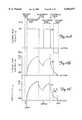
- FIGS. 11A, 11B, and 11Care graphs illustrating velocity and flow profiles of the extrusion head.
- the present inventionis used in a rapid prototyping system 10 in which three-dimensional objects are formed by depositing layers of a solidifying material from a moveable extrusion head.
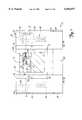
- the rapid prototyping system 10is contained within a cabinet 12, as shown in FIG. 1.
- the cabinet 12has doors and covers located on a front, left and right sides thereof.
- a modeling drybox door 22 and an electronics bay cover 24are located on the right hand side of cabinet 12.
- a support drybox door 26is located above a compressor bay cover 28 on the left hand side of cabinet 12.
- the upper right hand side of cabinet 12houses a modeling extrusion apparatus 30, which comprises a modeling extrusion head 32 attached below a modeling x-y forcer 33 and connected to the end of a modeling arm 34 which rotates about a modeling pivot joint 36.
- Modeling extrusion apparatus 30receives a filament of modeling material 40 from a modeling filament spool 42 located in a modeling drybox 45 (FIG. 2) below pivot joint 36 and accessible through modeling drybox door 22. Drybox 45 maintains low humidity conditions to optimize the condition of filament 40.
- Modeling extrusion apparatus 30is used to dispense modeling material in layers onto a substrate 60. Modeling filament spool 42 mounted on a modeling spindle 43 in drybox 45 is more clearly shown in FIG. 2.
- the left-hand side of cabinet 12houses a support extrusion apparatus 44, which is comprised of a support extrusion head 46 attached below a support x-y forcer 52 and connected to the end of a support arm 48 which rotates about a support pivot joint 50.
- Support extrusion apparatus 44receives a filament of support material 54 from a support filament spool 56 located in a support filament drybox 57 (FIG. 3) beneath support pivot joint 50 and accessible through support drybox door 26. Drybox 57 maintains low humidity conditions to optimize the condition of filament 54.
- Support extrusion apparatus 44is used to dispense support material in layers.
- Support filament spool 56 mounted on a support spindle 58 in drybox 57is more clearly shown in FIG. 3.
- Modeling material extruded in layers by modeling extrusion apparatus 30forms object 64.
- the support materialis used to support any over-hanging portions as the object is being built up. In building an object, over-hanging segments or portions which are not directly supported in the final geometry by the modeling material require a support structure.
- Support filament 54is supplied to support extrusion head 46 which deposits material to provide the required support.
- the support materiallike the modeling material, is deposited in multiple layers.
- FIG. 1the system 10 is shown building a three-dimensional object 64, with modeling extrusion apparatus 30 in an active build state, and support extrusion apparatus 44 in a home rest position.
- modeling filament 40travels through arm 34 to extrusion head 32, where is it heated to a liquid state.
- Layers of modeling material in a molten stateare deposited by head 32 through a liquifier 59 protruding through a bottom surface of head 32, onto substrate 60.
- Substrate 60is supported upon a vacuum platen 62 and held in place by vacuum forces.
- support head 46When support extrusion apparatus 44 is in an active build state, support head 46 similarly receives support filament 54 via arm 48, and heats it to a liquid state. Layers of support material in a molten state are deposited by head 46 through a liquifier 59 protruding through a bottom surface of head 32, onto substrate 60.
- the filaments of modeling and support materialsare each a solid material which can be heated relatively rapidly above its solidification temperature, and which will solidify upon a drop in temperature after being dispensed from the extrusion head.
- a composition having a relatively high adhesion to itself upon which it is deposited when hotis selected for the modeling material.
- a composition having a relatively low adhesion to the model material upon which it is depositedis selected for the support material, so that the support material forms a weak, breakable bond with the modeling material and to itself.
- the support materialis broken away by the operator, leaving the object formed of modeling material intact.
- the modeling materialis preferably a thermoplastic material.
- Other materials that may be used for the modeling material filamentinclude bees wax, casting wax, machinable and industrial waxes, paraffin, a variety of thermoplastic resins, metals and metal alloys. Suitable metals include silver, gold, platinum, nickel, alloys of those metals, aluminum, copper, gold, lead, magnesium, steel, titanium, pewter, manganese and bronze. Glass, and particularly Corning glass would also be satisfactory. Chemical setting materials, including two-part epoxies would also be suitable.
- a modeling material found to be particularly suitableis an acrylonitrile-butadiene-styrene (ABS) composition.
- ABSacrylonitrile-butadiene-styrene
- a material found to be particularly suitable for the support materialis an acrylonitrile-butadiene-styrene (ABS) composition with a polystyrene copolymer added as a filler (up to about 80%) to create a lower surface energy of the ABS composition, and to provide a lower cohesion and adhesion of the material.
- ABSacrylonitrile-butadiene-styrene
- Both filaments of materialare preferably of a very small diameter, on the order of 0.070 inch.
- the filamentmay, however, be as small as 0.001 inch in diameter.
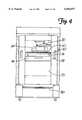
- FIG. 4shows a build envelope 70 which is the central interior region of the system 10, accessible through envelope door 14.
- the envelope 70is where a three-dimensional object is built.
- Envelope 70contains a build platform 74 which comprises vacuum platen 62 supported by a set of legs 76, which ride on a platform drawer 78.
- Build platform 74moves vertically in a z-direction within envelope 70. Movement of build platform 74 is controlled by a z-drive chain 80, driven by a z-motor 114 (shown schematically in FIG. 5).
- Build platform 74remains stationary during formation of a single layer. As each additional layer is deposited on substrate 60, build platform 74 is lowered slightly so as to allow a space for forming the subsequent layer. Platform drawer 78 pulls forward to allow the operator ready access to vacuum platen 62.
- An electrical system 90controls the system 10.
- a CPU 92together with first input/output (IO) card 94 and second input/output (IO) card 96, control the overall operation of the electrical system 90.
- CPU 92receives instructions from the operator through communication from touch screen display 21.
- CPU 92communicates with touch screen display 21 to display messages for the operator and to request input from the operator.
- CPU 92in turn communicates with IO cards 94 and 96.
- a power supply 98supplies power to electrical system 90.
- Envelope heaters 100 and envelope blower 102establish and maintain a temperature in the envelope 70 of approximately 80° C.
- An envelope thermal cutout (THCO) switch 108carries current through the machine's main contractor actuation coil. If the temperature reaches approximately 120° C. the THCO switch opens and current through the main contractor to the system is interrupted.
- the head blowers 104 and 106supply air at ambient temperature to cool the pathway of filaments 40 and 54 as they travel into modeling extrusion head 32 and support extrusion head 46, respectively.
- CPU 92also controls a compressor 110.
- Compressor 110supplies compressed air alternately to x-y forcers 33 and 52 and to the vacuum that is supplied to vacuum platen 62.
- CPU 92provides layering drive signals to selectively actuate the z-motor 114, which drives platform 74 along the z-axis.
- IO Card 94under the control of CPU 92, sends and receives signals associated with modeling extrusion head 32 and the filament supply thereto.
- IO card 94sends drive signals that control the movement and position of x-y forcer 33.
- IO card 94further sends and receives signals to and from modeling extrusion head 32, which includes a thermocouple 222 (TC), a heater 220 (HTR), a motor 246 (MTR) and a safety switch 210 (SS) (shown in FIGS. 8-10).
- Safety switch 210shuts down the system if the temperature in the modeling extrusion head 32 gets too high.
- IO card 94monitors data concerning modeling material filament spool 42 through communications with a modeling drybox processor board 116.
- Modeling drybox processor board 116is mounted inside of modeling filament drybox 45. It receives data concerning the modeling filament from a modeling filament sensor 118 (located at the inlet to filament guide 236, shown in FIG. 8) and a modeling EEPROM board 120, which is a circuit board carrying an electronically readable and writeable device (EEPROM 188, shown in FIG. 7), attached to modeling material filament spool 42.
- EEPROM board 120acts as an electronic tag with a variety of functions. It informs the control system 90 of the type of filament that is on the spool and of the lineal feet of filament on the spool.
- the CPU 92keeps track of how much material was commanded to be extruded, subtracts this amount from the total on the EEPROM 188 and writes the new value to the EEPROM 188 drybox.
- the data on EEPROM board 120is encrypted so that it can be updated only by the CPU 92.
- Filament sensor 118senses and indicates the presence or absence of filament at the entrance to the filament feed tube. With filament remaining on the spool, the operator can then grab ahold of the filament and extract it from the extrusion head 32. Unloading of the used filament and spool and reloading of a new spool is thereby made easier.
- CPU 92receives the modeling filament data from IO card 94.
- the CPU 92will calculate whether a spool 42 or 56 contains enough filament to complete the job. Operator notification is then provided via touch screen display 21, stating either that the filament is adequate to complete the job, or that the filament spool will need replacement and reloading during the process. Also at the outset of a job, the CPU verifies that the modeling filament material on the spool is the same material specified in object data. If these materials are not the same, an operator notification is provided via touch screen display 21, providing the operator an opportunity to switch spools.
- IO card 94additionally monitors the temperature in the envelope 70 via signals received from envelope thermocouple 122, and it sends signals to and from a modeling head proximity sensor 124, a high-z proximity sensor 126, a low-z proximity sensor 128 and an xyz noncontact tip position sensor 130, all of which are described below.
- IO card 96serves similar functions as IO card 94, for the support extrusion head 52 and the filament supply thereto.
- IO card 96sends drive signals that control the movement and position of x-y forcer 52.
- IO card 96further sends and receives signals to and from support extrusion head 46, which includes a thermocouple (TC), a heater (HTR), a motor (MTR) and a safety switch (SS).
- TCthermocouple
- HTRheater
- MTRmotor
- SSsafety switch
- the safety switch SSshuts down the system if the temperature in the modeling extrusion head 46 gets too high.
- IO card 96monitors data concerning support material filament spool 56 through communications with a support drybox processor board 132. It receives data concerning the support filament from a support filament sensor 134 and a support EEPROM board 136, attached to support material filament spool 56. EEPROM board 136 acts as an electronic tag, in the same manner as EEPROM board 120.
- CPU 92receives the support filament data from support processor board 132, and uses it to provide operator information in the same manner as described above with respect to the modeling filament.
- IO card 96further controls a first pressure valve 138 and a second pressure valve 140, which alternately open and shut to direct the flow of air from compressor 110.
- valve 138When valve 138 is closed and valve 140 is open, air from compressor 110 is directed to modeling head x-y forcer 33.
- valve 138When valve 138 is open and valve 140 is closed, air from compressor 110 is directed to support head x-y forcer 52.
- IO card 96in addition communicates with support head proximity sensor 142, which is described below.
- an operatorTo create an object using rapid prototyping system 10, an operator must first power up the system by pressing a power on switch (not shown), located on touch screen display 21. The system 10 then enters a maintenance mode, in which the system executes a routine to calibrate the locations of modeling extrusion head 32, support extrusion head 46, and build platform 74. The calibration is done in two phases. In the first phase, the system initializes movement boundaries for the extrusion heads and the platform. Modeling head proximity sensor 124 initializes boundaries of the modeling head 32, and support head proximity sensor 142 initializes boundaries of the support head 44. High-z proximity sensor 126 and low-z proximity sensor 128 together initialize the boundaries of platform 74.
- the xyz noncontact tip position sensor 130initializes the position of the tips of liquifiers 59 and 65.
- the xyz noncontact tip position sensor 130is a magnetic sensor imbedded in platform 74 which detects position of the liquifier tips with three displacement degrees of freedom.
- the systemexits the maintenance mode and enters a standby state.
- the design of a three-dimensional object 64is input to CPU 92 via a LAN network connection (shown schematically in FIG. 5) utilizing CAD software such as QUICKSLICE® from Stratasys, Inc., which sections the object design into multiple layers to provide multiple-layer data corresponding to the particular shape of each separate layer.
- the system 10enters a warmup phase, during which the envelope 70 is heated. Upon reaching a temperature of 80° C., the system enters a build state during which it creates the three-dimensional object.
- Modeling extrusion apparatus 30is shown more particularly in FIG. 6.
- Modeling extrusion apparatus 30is movable in a horizontal plane in x and y directions.
- Modeling x-y forcer 33is positioned beneath and parallel to a planar stator 150, which contains a grid of stator elements (not shown).
- x-y forcer 33 and planar stator 150form an electromagnetic linear stepper motor 152.
- Commercially available linear stepper motorare available from Northern Magnetics, Inc. of Santa Clarita, Calif.
- the x-y forcer 33consists of two sets of single-axis forcers mounted at 90° to each other and permanent magnets which hold forcer 33 against the stator (not shown).
- a compressed air supply 154supplied by compressor 110, is provided to x-y forcer 33 when modeling apparatus 30 is active.
- the compressed air supply 154flows upward through x-y forcer 33 and exits through a top surface thereof, as is illustrated in FIG. 6B.
- the exiting airforms an air bearing 156 between x-y forcer 33 and planar stator 150, which allows nearly frictionless motion of the forcer in a horizontal plane below planar stator 150.
- Drive signals to x-y forcer 33are received through an electrical supply 158 which powers a stepper motor driver located within x-y forcer 33 (not shown) to achieve motion.
- a stepper motor driverlocated within x-y forcer 33 (not shown) to achieve motion.
- linear stepper motors of this typeexhibit abrupt jarring motions which create mechanical resonance.
- Modeling extrusion arm 34is a flexible chain carrier that is flexible in a horizontal plane and substantially rigid in other directions. Arm 34 carries within it air supply 154 and forcer electrical supply 158. Arm 34 also carries within it a modeling extrusion head electrical supply 160 and a flexible air tube 162 which contains an ambient air supply and modeling filament 40, as depicted in FIG. 8. Arm 34 together with air supply 154, forcer electrical supply 158, extrusion head electrical supply 160 and air tube 162 containing filament 40 form an umbilical 163 to extrusion head 32.
- the umbilical 163creates the surprising result of damping the mechanical resonance of extrusion head 32 with respect to stator 30, which is produce by acceleration and deceleration of the head 32 by forcer 33.
- the combined weight of head 32 and x-y forcer 33is less than or equal to approximately 8 lbs.
- the resonant frequencyis about 55 Hz for small oscillations and about 45 Hz for large oscillations, and the damping time to achieve 98% of the final value (which is equal to approximately 4 times the damping time constant) in this embodiment is less than or equal to about 150 ms.
- the systemis approximately a factor often from being critically damped. Further damping can, therefore, be added if desired.
- the damping time constantis affected by the combined weight of extrusion head 32 and x-y forcer 33. The lighter the weight, the shorter the damping time constant.
- Damping of mechanical resonanceis achieved primarily by frictional forces produced during movement of umbilical 163.
- other forms of damping meanscan be used, such as an oscillation dissipater (or shock-absorber) carried in extrusion head 32.
- further dampingcan be produced by decreasing the resistivity of the bucking of starter 150 (such as by using copper rather than steel) to increase eddy current losses within stator 150.
- support head apparatus 44has a similar structure and has an umbilical of the same type described with reference to modeling apparatus 30. Specifically, support x-y forcer 52 shares the planar stator 150 such that x-y forcer 52 and stator 150 form a second linear motor. Support apparatus 44 starts from the opposite side of cabinet 12 from modeling apparatus 30. For ease of reference, only one head is shown in detail.
- Vacuum platen 62 and substrate 60are shown in an exploded fashion in FIG. 6.
- Vacuum platen 62has a top surface 167 comprised of a grid of grooves 164, shown in detail in FIG. 6A.
- grooves 164are 0.06 inches deep, 0.06 inches wide, and are 1 inch on center apart.
- An orifice 166extends through the center of vacuum platen 62. Orifice 166 receives a vacuum hose 168 which connects to vacuum pump 112.
- a vacuumis applied to vacuum platen 62 by vacuum hose 168 and vacuum pump 112.
- the vacuum provided to platen 62pulls air through grooves 164 to distribute the vacuum along the platen.
- substrate 60is a flexible sheet.
- a polymeric materialforms a suitable flexible sheet substrate.
- An acrylic sheet with a thickness of about 0.06 incheshas been successfully used as a substrate.
- Flexible substrate 60can be flexed away from the object to peel the substrate from the object, if there is a weak breakable bond between substrate 60 and the object.
- This weak, breakable bondmay be formed by depositing a first layer (or layers) of modeling material followed by a second layer (or layers) of support material on the substrate 60.
- the modeling material and substrateare selected so that the modeling material is fully adhesive to the substrate.
- the modeling materialis deposited in one or more layers on the substrate 60.
- the support materialis then deposited in one or more layers over the modeling material.
- the objectis then built up on the support material, using a plurality of layers of modeling and/or support material.
- the objectWhen the object is complete, vacuum is broken by lifting a corner of the substrate 60, and the substrate 60 is removed from the platen 62 by the operator. By flexing the substrate 60, the operator then peels the substrate 60 from the object.
- the first layer(s) of modeling materialwill remain adhered to the substrate, but the weak bond between the first layer(s) of modeling material and the second layer(s) of support material is a readily separable joint which breaks to allow removal of the substrate 60 without damage to the object.
- substrate 60may be used as substrate 60.
- plain or coated paper, metal foil and other polymeric materialsare suitable.
- a polymeric materiale.g., Kapton
- metal foilis particularly desirable.
- a vacuumis a preferred way to achieve a releasable hold down force to hold substrate 60 against platen 62
- other means for providing a releasable hold down forcecan also be used.
- substrate 60can be held against platen 62 by an electrostatic chuck or by a weakly adhering adhesive applied to the bottom surface of the substrate 60 or the top surface of the platen 62 (or both).
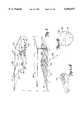
- FIG. 7shows a detailed exploded view of the filament spool and spindle shown in FIGS. 2 and 3.
- the mechanical configuration of the filament spool and spindleis identical for both the modeling filament and the support filament.
- FIG. 7is directed specifically to modeling filament spool 42 and modeling spindle 43.
- Spindle 43extends horizontally from drybox 45 and has a semi-circular shape.
- a semi-circular connector 174 having a set of six depressible connector pins 176is mounted on top of spindle 43 adjoining drybox 45.
- a spring-loaded latch 178is embedded in the top of spindle 43 at an outer edge 179.
- Filament spool 42is comprised of a center barrel 180 on which filament may be wound, a pair of spool flanges 181 extending from either end of barrel 180, a sleeve 182 that fits within barrel 180 for receiving spindle 43, and modeling EEPROM board 120 mounted inside sleeve 182 and perpendicular to barrel 180.
- Barrel 180rotates about sleeve 182 so that filament 40 may be unwound from spool 42.
- Sleeve 182has a flange 184 at one end, a flange 186 at the opposite end, and an interior semi-circular cavity for receiving spindle 43.
- flange 184is removable and flange 186 is fixed.
- EEPROM board 120carries EEPROM 188.
- EEPROM board 120is mounted adjacent fixed flange 186 by a pair of screws 190, so that EEPROM 188 faces inward towards sleeve 182 for protection.
- EEPROM board 120 on its outward facing sidecarries a set of six round electrical contacts 192, as shown in FIG. 7A.
- Connectors 192are configured so as to provide a receiving surface for connector pins 176 when spool 42 is mounted on spindle 43.
- Latch 178must be manually depressed to allow insertion or removal of spindle 43 from sleeve 182.
- latch 179rests in an upward position so as to lock spool 42 into place such that contacts 192 fully depress connector pins 176.
- electrical contact between EEPROM board 120 and drybox processor board 116is made through the connector 190.
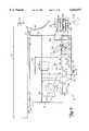
- FIG. 8shows modeling extrusion apparatus 30, it should be understood that support extrusion apparatus 44 contains the same parts and operates in the same manner as modeling extrusion apparatus 30, at a 180° rotation.
- Extrusion head 32is mounted below x-y forcer 38 by a pair of mounting plates 200. Two pairs of bolts 202 attach head 32 to plates 200. Two bolts 204 connect plates 200 to x-y forcer 38 to hold head 32.
- Extrusion head 32is formed of an enclosure 206 which holds liquifier 59, a filament drive 208 and safety switch 210.
- Liquifier 59comprises a thermal conducting thin-wall tube 212, a heating block 214, an extrusion tip 216, a tip retainer 218, heater 220 and thermocouple 222.
- FIG. 9shows liquifier 59 in an exploded view. As shown in FIG. 9, thin-wall tube 212 has an inlet end 224, an outlet end 226, and is bent at a 90° angle. In the preferred embodiment, tip 216 is soldered into the outlet end of tube 212. Alternatively, tip 216 may be brazed or welded to tube 212.
- tube 212may be formed in the tube itself by swaging the outlet end 226 of the tube.
- tube 212preferably has an inner diameter of about 0.074 inches.
- the wall thickness of tube 212is preferably between 0.005-0.015 inches. It is desirable to keep tube 212 as thin as possible to achieve maximum heat transfer across tube 212 to filament 40.
- tube 212is made of stainless steel.
- Other metalsmay also be used, such as brass, copper, tungsten, titanium, molybdenum, beryllium copper or other steels.
- Other thermal conducting materialssuch as polymide (Kapton), a plastic with a high melting temperature, may also be used to form the thin-wall tube.
- Tube 212fits into a channel 229 of heating block 214, between a front section 228 and a rear section 230 of the heating block.
- Heating block 214is made of a heat conductive material such as aluminum or beryllium copper.
- a set of four bolts 232extend through outer section 228 and rear section 230 of heating block 214 to hold tube 212.
- a first section of tube 212 adjacent the inlet end 224is exterior to heating block 214, and a second mid-section of tube 212 is clamped within heating block 214, and a third section of tube 212 including tip 216 extends through the bottom of block 214.
- the first section of tube 212forms a cap zone for the liquifier 59
- the second section of tube 212forms a heating zone
- the third sectionforms a nozzle zone.
- the nozzle zoneis contained within and silver soldered to extrusion tip 216, which is supported against heating block 214 by tip retainer 218, a square plate having a center orifice.
- Tip retainer 218is press fit around the extrusion tip 216, and mounted beneath heating block 214 by a pair of screws 234.
- the length of the cap zone of tube 212is in the range of 0.15 inches and 2 inches.
- the cap zonemust undergo a temperature gradient from about 70 degrees C envelope temperature to about 280 degrees C liquifier temperature.
- a shorter cap zoneallows for greater control by the system over the rate that molten filament is extruded (i.e., flow rate), but makes it more difficult to maintain a cool temperature for the filament through the cap zone.
- the length of the heating zoneis anywhere from 0.04 inches to 7 inches. The longer the heating zone, the higher the maximum extruded flow rate, but the slower that the flow rate can be accelerated and decelerated.
- a liquifier having a cap zone of between 0.02-0.04 inches long and a heating zone of about 2.5 inches longhas been successfully used in a preferred embodiment of the system.
- Cylindrical heater 220 and thermocouple 222extend horizontally into rear section 230 of heating block 214.
- Heater 220is positioned in heat exchange relation to the heating zone of tube 212, to heat the tube to a temperature just above the melting temperature of the filament.
- the tubeis heated to about 270 degrees C.
- Thermocouple 222is positioned adjacent tube 212 to monitor the temperature in the tube.
- Safety switch 210will cause the system 10 to shut down if temperature exceeds a predetermined level.
- a guide tube 236guides filament 40 from pivot 36 to extrusion head 32, made of a suitable low friction material such as Teflon for support in motion.
- filament 40 within guide tube 36are located within flexible tube 60 contained inside of arm 34.
- Filament 40enters extrusion head 32 through an inlet aperture 238.
- filament 40is fed through a tapered guide 240 having a restricted guide passage 242.
- Filament drive 208is comprised of a stepper motor 246, a pulley 248 and a pair of feed rollers 250 and 252.
- Roller 250has a drive shaft 254 which is driven by stepper motor 246.
- Roller 252is a rubber-coated idler.
- Filament 40is fed from the guide passage 242 of tapered guide 240 into a nip between rollers 250 and 252.
- the rotation of roller 250advances filament 40 towards liquifier 59.
- the inlet end 224 of thin-wall tube 212is positioned to receive filament 40 as it passes through rollers 250 and 252.
- the flow rate of the molten filament out of liquifier 59is controlled by the speed at which filament drive 208 advances the filament 40 into liquifier 59.
- a blower 256blows air at ambient temperature into flexible tube 60 to cool guide tube 236 and filament 40. Cooling of strand 40 is important so as to maintain the filament at a sufficiently low temperature that is does not become limp and buckled within the passages leading into the liquifier 59. Air from blower 256 travels through tube 60 and enters extrusion head 32 via an air conduit 258. Air conduit 258 provides a path for the air which is in a forward and parallel position from filament 40 within extrusion head 32.
- FIGS. 10A and 10Bshow an alternative embodiment of the liquifier.
- FIG. 10Ashows liquifier 259 in an assembled view
- 10Bshows liquifier 259 in an exploded view.
- two thin-wall tubes 260A and 260B of the type described aboveflow into one, nozzle 262.
- a liquifier of this typecan be substituted into the dispensing head shown in FIG. 8 to provide one extrusion head that dispenses, at alternate times, two different deposition materials.
- the two deposition materialsmay be a modeling and a supply material, or they may be modeling materials of two different colors or having other diverse properties.
- Nozzle 262is brazed or welded to the outlet ends 264 of tubes 260A and 260B.
- Nozzle 262is positioned in a vertical orientation, while tubes 260A and 260B may be angled towards the horizontal. Separate feed mechanisms (not shown) are provided for tubes 260A and 260B so that filament material is fed into only one of the tubes at any given time.
- Thin-wall tubes 260A and 260Bare held into position by a heating block 266.
- Heating block 266is comprised of an outer plate 268, an interior plate 270 and a rear plate 272.
- Rear plate 272is mounted within the extrusion head, and holds a heater 274 which extends between tubes 260.
- Two channels 276 which hold tubes 260A and 260Bare routed through interior block 270.
- a set of five boltsextend through outer plate 268, interior plate 270 and rear plate 272 to detachably hold together liquifier 259. It is an advantageous that the liquifier be removable from the heating block, for replacement and cleaning.
- both modeling extrusion head 32 and support extrusion head 46is maintained proportional to the flow rates of modeling and support material extruded by each head, respectively. Slaving head velocity to flow rates allows control over the bead size of extruded material while achieving a high throughput.
- Modeling extrusion head 32carrying liquifier 59, moves at a variable head velocity V H in x and y directions.
- CPU 92controls head velocity V H by controlling linear stepper motor 152 which drives extrusion head 32.
- Extrusion head 32delivers liquified filament 40 at a variable extruded pump flow rate Q P .
- the extruded pump flow rate Q Pis dependent on the time response of liquifier 59 in providing or ceasing to provide liquified filament, represented by a time constant ⁇ , and upon a velocity V D at which filament drive 208 operates to advance filament 40 into liquifier 59.
- filament drive 208 and liquifier 59form a pump which provides liquified filament for extrusion, at a rate that determines pump flow rate Q P .
- CPU 92controls extruded pump flow rate Q P by providing control signals to stepper motor 146 which drives filament drive 208.
- the material extruded by extrusion head 32has a bead size that is related to both the extruded pump flow rate Q P and the extrusion head velocity V H .
- the bead sizeremain constant, although applications may arise where it is desired that bead size vary according to, for example, a sinusoidal function.
- Movement of extrusion head 32is more quickly and easily controlled than the rate at which material is extruded by the extrusion head 32. Additionally, in an open-loop system such as rapid prototyping system 10, there is no feedback measuring actual flow rate, so extruded pump flow rate Q P is estimated using experimental methods.
- the velocity profiles of the present inventionthus coordinate head velocity V H with operation of the extrusion pump (liquifier 59 together with filament drive 208, in the preferred embodiment described), maintaining extrusion head velocity V H proportional to an estimated profile of the extruded pump flow rate Q P .
- the estimated profile of extruded pump flow rate Q P and the liquifier time constant ⁇may be obtained using any number of possible methods known to those skilled in the art. It should be understood that the flow rate profile is unique to a given extrusion system. In the preferred embodiment described herein, experimentation has yielded that, for a step input control of stepper motor 246 of filament drive 208, extruded pump flow rate Q P has a response that fits to an exponential function dependent upon the liquifier time constant. Accordingly, in the preferred embodiment described herein, velocity of extrusion head 32 is controlled according to the estimated exponential profile of extruded pump rate Q P .
- the flow rate profile for a given extrusion systemmay alternatively be fitted to other types of time-responsive functions, for example, a polynomial function.
- FIGS. 11A, 11B, and 11Care graphs illustrating respectively filament drive velocity V D , extruded pump flow rate Q P and extrusion head velocity V H as extrusion head 32 proceeds through a path composed of a start point, a vertex point, and a stop point. It should be understood that the path followed by extrusion head 32 would generally comprise multiple vertices.
- the points along the pathare generated by a move-compiler (not shown) in a known manner, and provided to CPU 92.
- the move-compileralso determines and provides to CPU 92 for each vertex a vertex velocity V V , which is the maximum velocity at which extrusion head 32 can be driven through that vertex without exceeding an allowable error.
- CPU 92In moving extrusion head 32 through the path, CPU 92 ideally accelerates head velocity V H toward a steady-state velocity V SS , decelerates head velocity V H to zero velocity, or adjusts head velocity V H to achieve a vertex velocity V V . As shown in FIG. 11A, filament drive 208 is generally either off or operating at steady-state velocity V SS .
- the rapid prototyping system 10goes through four extrusion phases (pre-pump, acceleration, deceleration, and suck-back), each of which are also illustrated in FIGS. 11A, 11B, and 11C.
- the velocity profiles of the present inventionare specific to each of the four phases.
- the first phase that the system goes throughis the pre-pump (or charging) phase.
- the pre-pump (or charging) phaseUpon initially engaging filament drive 208, there is a pre-pump time delay T PP before any material is extruded from the extrusion pump.
- T PPtime delay
- filament drive 208runs at a pre-pump velocity V D ,PP that is greater than steady-state velocity V SS .
- the acceleration phasebegins once extrusion head 32 begins extruding material.
- the goal of the acceleration phaseis to accelerate head velocity V H until it reaches the steady-state velocity V SS .
- head velocity V Hmust be stopped before reaching steady-state velocity V SS at an intermediate velocity V I because reaching steady-state velocity V SS would make it impossible to decelerate fully to the vertex velocity V V associated with the next vertex.
- This intermediate velocity V Iis the maximum velocity from which the head velocity V H can be decelerated to reach the velocity desired at the next vertex.
- velocity V D of filament drive 208is held at steady-state velocity V SS .
- pump flow rate Q Pincreases exponentially. Extruded pump flow rate Q P can be modeled by the following equation:
- Q SSis the steady-state flow rate and ⁇ A is the acceleration time constant that defines the exponential increase in pump flow rate Q P .
- the steady-state flow rate Q SSis defined as the maximum rate at which extrusion head 32 can extrude the liquified filament of material.
- the length of time required for extruded pump flow rate Q P to increase from zero to steady-state flow rate Q SSis approximately five acceleration time constants ⁇ A .
- acceleration time constant ⁇ Ais less than 0.05 seconds, allowing for the pump flow rate to be rapidly increased.
- head velocity V His slaved to extruded pump flow rate Q P , head velocity V H is similarly defined by the following equation:
- steady-state velocity V SSequals steady-state flow rate Q SS divided by the desired cross-sectional area of the bead extruded by extrusion head 32.
- the acceleration of extrusion head 32, during the acceleration phase,is defined by the following equation: ##EQU1## where V SS / ⁇ A is the maximum acceleration of extrusion head 32.
- extrusion head 32Once modeling extrusion head 32 reaches either the steady-state velocity V SS or the intermediate velocity V I , extrusion head 32 enters the deceleration phase, where filament drive 208 is turned off.
- the goal of the deceleration phaseis to decelerate head velocity V H until it reaches either zero or, if applicable, vertex velocity V V .
- extruded pump flow rate Q Pdecreases exponentially, as defined by the following equation:
- ⁇ Dis the deceleration time constant that defines the exponential decrease in pump flow rate Q P .
- deceleration time constant ⁇ Dis less than 0.05 seconds, allowing for the pump flow rate to be rapidly decelerated.
- the time constant associated with liquifier 59may remain constant throughout each phase of the system; however, the time constant may also have a different value for each phase. In a system in which the time constant remains constant regardless of phase, the acceleration time constant ⁇ A and the deceleration time constant ⁇ D in the above equations could be replaced with a singular time constant ⁇ .
- the suck-back phaseis employed as modeling extrusion head 32 approaches a stop.
- filament drive 208reverses direction and operates at a constant suck-back velocity V SB to prevent excess material from being extruded.
- modeling extrusion head 32must continue moving during the suck-back phase to maintain a consistent bead size.
- extrusion head velocity V Hremains the same as that of the deceleration phase. Because it would take infinitely long for extrusion head velocity V H to reach zero when following an exponential profile, the exponential head velocity profile is replaced with a linear profile for extrusion head velocities V H not exceeding a suck-back trip velocity V SBT . Once extrusion head velocity V H reaches suck-back trip velocity V SBT , extrusion head velocity is changed from the suck-back exponential profile, which is identical to the deceleration phase exponential profile, to the suck-back phase linear profile:
- a SBis the slope of the linear profile.
- a SBcan be calculated as the negative of the initial acceleration in head velocity V H during the acceleration phase.
- the velocity profiling of the present inventionhas application in other rapid prototyping systems, as well as in robotic extrusion systems used in other fields.
- the extrusion pumpmay be other than the liquifier and filament drive of the preferred embodiment described.
- the extrusion pumpmay be any flow motivator, including a piston pump, viscosity pump, displacement pump, centripetal pump or an acoustic pump.
- the extruded pump flow rate in such systemcan be measured experimentally to obtain an estimated flow rate profile as discussed herein, and the extrusion head velocity slaved to the estimated profile according to the present invention.
- Other fields in which velocity profiling can be appliedinclude adhesive dispensing applications (e.g., assembly of cars, diapers, boxes and clothing) and solder paste extrusion (used, for example, in fabrication of circuit boards).
Landscapes
- Engineering & Computer Science (AREA)
- Mechanical Engineering (AREA)
Abstract
Description
Q.sub.P,A (t)=Q.sub.SS (1-e.sup.-t/τ.sbsp.A)
V.sub.H,A (t)=V.sub.SS (1-e.sup.-t/τ.sbsp.A)
Q.sub.P,D (t)=Q.sub.SS e.sup.-t/τ.sbsp.D
V.sub.H,D (t)=V.sub.SS e.sup.-t/τ.sbsp.D.
V.sub.H,SB (t)=V.sub.SBT +A.sub.SB t
Q.sub.P,PP (t)=0
V.sub.H,PP (t)=0
Q.sub.P,A (t)=(1786 μin.sup.3 /sec)(1-e.sup.-t/0.025 sec)
V.sub.H,A (t)=(10 in/sec)(1-e.sup.-t/0.025 sec)
Q.sub.P,D (t)=(1786 μin.sup.3 /sec)(e.sup.-t/0.025 sec)
V.sub.H,D (t)=(10 in/sec)(e.sup.-t/0.025 sec)
Q.sub.P,SB (t)=(1786 μin.sup.3 /sec)(e.sup.-t/0.025 sec)
V.sub.H,D (t)=(10 in/sec)(e.sup.-t/0.025 sec) (for V.sub.H,SB ≦V.sub.SBT)
V.sub.H,SB (t)=(0.3 in/sec)-(400 in/sec.sup.2)t (for V.sub.H,SB >V.sub.SBT)
Claims (24)
Priority Applications (1)
| Application Number | Priority Date | Filing Date | Title |
|---|---|---|---|
| US09/228,095US6054077A (en) | 1999-01-11 | 1999-01-11 | Velocity profiling in an extrusion apparatus |
Applications Claiming Priority (1)
| Application Number | Priority Date | Filing Date | Title |
|---|---|---|---|
| US09/228,095US6054077A (en) | 1999-01-11 | 1999-01-11 | Velocity profiling in an extrusion apparatus |
Publications (1)
| Publication Number | Publication Date |
|---|---|
| US6054077Atrue US6054077A (en) | 2000-04-25 |
Family
ID=22855771
Family Applications (1)
| Application Number | Title | Priority Date | Filing Date |
|---|---|---|---|
| US09/228,095Expired - LifetimeUS6054077A (en) | 1999-01-11 | 1999-01-11 | Velocity profiling in an extrusion apparatus |
Country Status (1)
| Country | Link |
|---|---|
| US (1) | US6054077A (en) |
Cited By (151)
| Publication number | Priority date | Publication date | Assignee | Title |
|---|---|---|---|---|
| US20010038168A1 (en)* | 1999-06-23 | 2001-11-08 | Stratasys, Inc. | Method and apparatus for three-dimensional modeling |
| EP1080867A3 (en)* | 1999-09-03 | 2002-09-11 | DATRON-ELECTRONIC GmbH | Method for dosed distribution of a strand formed from a viscous material and metering pump for carrying out said method |
| US20030004600A1 (en)* | 2001-05-11 | 2003-01-02 | Stratasys, Inc. | Material and method for three-dimensional modeling |
| US20030056870A1 (en)* | 2001-09-21 | 2003-03-27 | Stratasys, Inc. | High-precision modeling filament |
| WO2003026872A1 (en)* | 2001-09-21 | 2003-04-03 | Stratasys, Inc. | Melt flow compensation in an extrusion apparatus |
| US20040104515A1 (en)* | 1999-06-23 | 2004-06-03 | Stratasys, Inc. | High-Temperature modeling method |
| US6814907B1 (en) | 2001-12-18 | 2004-11-09 | Stratasys, Inc. | Liquifier pump control in an extrusion apparatus |
| US20050004282A1 (en)* | 1999-04-20 | 2005-01-06 | Stratasys, Inc. | Soluble material and process for three-dimensional modeling |
| US20050023710A1 (en)* | 1998-07-10 | 2005-02-03 | Dmitri Brodkin | Solid free-form fabrication methods for the production of dental restorations |
| US6998087B1 (en)* | 2001-04-30 | 2006-02-14 | Stratasys, Inc. | Extrusion method for three dimensional modeling |
| US20060158456A1 (en)* | 2005-01-18 | 2006-07-20 | Stratasys, Inc. | High-resolution rapid manufacturing |
| US20070001050A1 (en)* | 2005-06-30 | 2007-01-04 | Stratasys, Inc. | Cassette spool lock |
| US20070003656A1 (en)* | 2005-07-01 | 2007-01-04 | Stratasys, Inc. | Rapid prototyping system with controlled material feedstock |
| US7169229B2 (en)* | 1998-01-09 | 2007-01-30 | Fastar, Ltd. | Moving head, coating apparatus |
| US20070179657A1 (en)* | 2006-01-31 | 2007-08-02 | Stratasys, Inc. | Method for building three-dimensional objects with extrusion-based layered deposition systems |
| US7261542B2 (en) | 2004-03-18 | 2007-08-28 | Desktop Factory, Inc. | Apparatus for three dimensional printing using image layers |
| US20070228590A1 (en)* | 2006-04-03 | 2007-10-04 | Stratasys, Inc. | Single-motor extrusion head having multiple extrusion lines |
| US20070228592A1 (en)* | 2006-04-03 | 2007-10-04 | Stratasys, Inc. | Auto tip calibration in an extrusion apparatus |
| US20070233298A1 (en)* | 2006-04-03 | 2007-10-04 | Stratasys, Inc. | Method for optimizing spatial orientations of computer-aided design models |
| US20080213419A1 (en)* | 2007-02-12 | 2008-09-04 | Stratasys, Inc. | Viscosity pump for extrusion-based deposition systems |
| WO2008156870A1 (en)* | 2007-06-21 | 2008-12-24 | Stratasys, Inc. | Extrusion tip cleaning assembly |
| US20090018685A1 (en)* | 2007-07-11 | 2009-01-15 | Stratasys, Inc. | Method for building three-dimensional objects with thin wall regions |
| US20090035405A1 (en)* | 2007-07-31 | 2009-02-05 | Stratasys, Inc. | Extrusion head for use in extrusion-based layered deposition modeling |
| US20090177309A1 (en)* | 2008-01-08 | 2009-07-09 | Stratasys, Inc. | System for building three-dimensional objects containing embedded inserts, and method of use thereof |
| US20090173443A1 (en)* | 2008-01-08 | 2009-07-09 | Stratasys, Inc. | Method for building and using three-dimensional objects containing embedded identification-tag inserts |
| US20090174709A1 (en)* | 2008-01-08 | 2009-07-09 | Stratasys, Inc. | Method for building three-dimensional objects containing embedded inserts |
| US20090263582A1 (en)* | 2008-04-18 | 2009-10-22 | Stratasys, Inc. | Digital manufacturing with amorphous metallic alloys |
| US20090273122A1 (en)* | 2008-04-30 | 2009-11-05 | Stratasys, Inc. | Liquefier assembly for use in extrusion-based digital manufacturing systems |
| US20090314391A1 (en)* | 2008-06-24 | 2009-12-24 | Stratasys, Inc. | System and method for building three-dimensional objects with metal-based alloys |
| US20100140849A1 (en)* | 2007-03-22 | 2010-06-10 | Stratasys, Inc. | Extrusion-based layered deposition systems using selective radiation exposure |
| US20100161105A1 (en)* | 2008-12-22 | 2010-06-24 | Stratasys, Inc. | Combined process for building three-dimensional models |
| US20100166969A1 (en)* | 2007-04-19 | 2010-07-01 | Stratasys, Inc. | Syringe tip assembly and layered deposition systems utilizing the same |
| US20100193998A1 (en)* | 2009-02-02 | 2010-08-05 | Stratasys, Inc. | Inorganic ionic support materials for digital manufacturing systems |
| US20100327479A1 (en)* | 2009-06-23 | 2010-12-30 | Stratasys, Inc. | Consumable materials having customized characteristics |
| US7896209B2 (en) | 2008-04-30 | 2011-03-01 | Stratasys, Inc. | Filament drive mechanism for use in extrusion-based digital manufacturing systems |
| US20110070394A1 (en)* | 2009-09-23 | 2011-03-24 | Stratasys, Inc. | Seam concealment for three-dimensional models |
| US20110076496A1 (en)* | 2009-09-30 | 2011-03-31 | Stratasys, Inc. | Non-cylindrical filaments for use in extrusion-based digital manufacturing systems |
| US20110074065A1 (en)* | 2009-09-30 | 2011-03-31 | Stratasys, Inc. | Ribbon liquefier for use in extrusion-based digital manufacturing systems |
| US20110076495A1 (en)* | 2009-09-30 | 2011-03-31 | Stratasys, Inc. | Consumable materials having topographical surface patterns for use in extrusion-based digital manufacturing systems |
| US20110117268A1 (en)* | 2009-11-19 | 2011-05-19 | Stratasys, Inc. | Consumable materials having encoded markings for use with direct digital manufacturing systems |
| US20110121476A1 (en)* | 2009-11-19 | 2011-05-26 | Stratasys, Inc. | Encoded consumable materials and sensor assemblies for use in additive manufacturing systems |
| US20110199104A1 (en)* | 2010-02-16 | 2011-08-18 | Stratasys, Inc. | Capacitive detector for use in extrusion-based digital manufacturing systems |
| USD660353S1 (en) | 2010-12-22 | 2012-05-22 | Stratasys, Inc. | Print head |
| US20120132292A1 (en)* | 2008-03-12 | 2012-05-31 | Whirlpool Corporation | Vacuum compartment in refrigerator |
| US8419996B2 (en) | 2010-12-22 | 2013-04-16 | Stratasys, Inc. | Print head assembly for use in fused deposition modeling system |
| US8512024B2 (en) | 2011-01-20 | 2013-08-20 | Makerbot Industries, Llc | Multi-extruder |
| US8647102B2 (en) | 2010-12-22 | 2014-02-11 | Stratasys, Inc. | Print head assembly and print head for use in fused deposition modeling system |
| US8647098B2 (en) | 2010-09-22 | 2014-02-11 | Stratasys, Inc. | Liquefier assembly for use in extrusion-based additive manufacturing systems |
| US8663533B2 (en) | 2010-12-22 | 2014-03-04 | Stratasys, Inc. | Method of using print head assembly in fused deposition modeling system |
| US8815141B2 (en) | 2010-09-22 | 2014-08-26 | Stratasys, Inc. | Method for building three-dimensional models with extrusion-based additive manufacturing systems |
| US20140263534A1 (en)* | 2013-03-15 | 2014-09-18 | Elijah Post | Winchester print head |
| US8926484B1 (en) | 2010-03-29 | 2015-01-06 | Stratasys, Inc. | Head tool changer for use with deposition-based digital manufacturing systems |
| US8961167B2 (en) | 2012-12-21 | 2015-02-24 | Stratasys, Inc. | Automated additive manufacturing system for printing three-dimensional parts, printing farm thereof, and method of use thereof |
| US8986767B2 (en) | 2011-03-30 | 2015-03-24 | Stratsys, Inc. | Additive manufacturing system and method with interchangeable cartridges for printing customized chocolate confections |
| US8985497B2 (en) | 2011-12-22 | 2015-03-24 | Stratasys, Inc. | Consumable assembly with payout tube for additive manufacturing system |
| US9022769B2 (en) | 2010-07-22 | 2015-05-05 | Stratasys, Inc. | Multiple-zone liquefier assembly for extrusion-based additive manufacturing systems |
| US20150147427A1 (en)* | 2013-11-25 | 2015-05-28 | Michael Lundwall | Extrusion heads |
| US9050788B2 (en) | 2011-12-22 | 2015-06-09 | Stratasys, Inc. | Universal adapter for consumable assembly used with additive manufacturing system |
| US9050753B2 (en) | 2012-03-16 | 2015-06-09 | Stratasys, Inc. | Liquefier assembly having inlet liner for use in additive manufacturing system |
| US9073263B2 (en) | 2011-12-22 | 2015-07-07 | Stratasys, Inc. | Spool assembly for additive manufacturing system, and methods of manufacture and use thereof |
| US9090428B2 (en) | 2012-12-07 | 2015-07-28 | Stratasys, Inc. | Coil assembly having permeable hub |
| USD741149S1 (en) | 2014-07-21 | 2015-10-20 | Stratasys, Inc. | Filament spool |
| US9168697B2 (en) | 2012-08-16 | 2015-10-27 | Stratasys, Inc. | Additive manufacturing system with extended printing volume, and methods of use thereof |
| US9174388B2 (en) | 2012-08-16 | 2015-11-03 | Stratasys, Inc. | Draw control for extrusion-based additive manufacturing systems |
| US9216544B2 (en) | 2012-12-21 | 2015-12-22 | Stratasys, Inc. | Automated additive manufacturing system for printing three-dimensional parts, printing farm thereof, and method of use thereof |
| US9215882B2 (en) | 2011-03-30 | 2015-12-22 | Stratasys, Inc. | Additive manufacturing system and method for printing customized chocolate confections |
| US9233506B2 (en) | 2012-12-07 | 2016-01-12 | Stratasys, Inc. | Liquefier assembly for use in additive manufacturing system |
| US9238329B2 (en) | 2010-12-22 | 2016-01-19 | Stratasys, Inc. | Voice coil mechanism for use in additive manufacturing system |
| WO2016049642A1 (en) | 2014-09-26 | 2016-03-31 | Stratasys, Inc. | Liquefier assemblies for additive manufacturing systems, and methods of use thereof |
| US9321609B2 (en) | 2012-12-07 | 2016-04-26 | Stratasys, Inc. | Filament drive mechanism for use in additive manufacturing system |
| US9321608B2 (en) | 2011-12-22 | 2016-04-26 | Stratasys, Inc. | Spool assembly with locking mechanism for additive manufacturing system, and methods of use thereof |
| US9327350B2 (en) | 2012-08-16 | 2016-05-03 | Stratasys, Inc. | Additive manufacturing technique for printing three-dimensional parts with printed receiving surfaces |
| US9327447B2 (en) | 2013-10-04 | 2016-05-03 | Stratasys, Inc. | Liquefier assembly for additive manufacturing systems, and methods of use thereof |
| US9364986B1 (en) | 2012-05-22 | 2016-06-14 | Rapid Prototype and Manufacturing LLC | Method for three-dimensional manufacturing and high density articles produced thereby |
| US9399320B2 (en) | 2013-03-08 | 2016-07-26 | Stratasys, Inc. | Three-dimensional parts having interconnected hollow patterns, and method for generating and printing thereof |
| US9421713B2 (en) | 2013-03-08 | 2016-08-23 | Stratasys, Inc. | Additive manufacturing method for printing three-dimensional parts with purge towers |
| US9511547B2 (en) | 2012-08-16 | 2016-12-06 | Stratasys, Inc. | Method for printing three-dimensional parts with additive manufacturing systems using scaffolds |
| US9527240B2 (en) | 2013-03-15 | 2016-12-27 | Stratasys, Inc. | Additive manufacturing system and method for printing three-dimensional parts using velocimetry |
| US9610733B2 (en) | 2015-01-06 | 2017-04-04 | Stratasys, Inc. | Additive manufacturing with soluble build sheet and part marking |
| US9636868B2 (en) | 2012-08-16 | 2017-05-02 | Stratasys, Inc. | Additive manufacturing system with extended printing volume, and methods of use thereof |
| US9694545B2 (en) | 2014-12-18 | 2017-07-04 | Stratasys, Inc. | Remotely-adjustable purge station for use in additive manufacturing systems |
| US9744730B2 (en) | 2013-11-22 | 2017-08-29 | Stratasys, Inc. | Magnetic platen assembly for additive manufacturing system |
| WO2017153195A1 (en)* | 2016-03-08 | 2017-09-14 | Cl Schutzrechtsverwaltungs Gmbh | Apparatus for the additive manufacturing of a three-dimensional object |
| US9802360B2 (en) | 2013-06-04 | 2017-10-31 | Stratsys, Inc. | Platen planarizing process for additive manufacturing system |
| US20180029307A1 (en)* | 2016-07-28 | 2018-02-01 | Robert Bosch Tool Corporation | Temperature control system for 3d printer extrusion head |
| WO2018039261A1 (en) | 2016-08-22 | 2018-03-01 | Stratasys, Inc. | Methods of printing 3d parts with localized thermal cycling |
| US20180093420A1 (en)* | 2016-09-30 | 2018-04-05 | Robert Robert Olson | Calibrated 3-D Printing |
| US9950474B2 (en) | 2013-09-13 | 2018-04-24 | Statasys, Inc. | Additive manufacturing system and process with precision substractive technique |
| US10029415B2 (en) | 2012-08-16 | 2018-07-24 | Stratasys, Inc. | Print head nozzle for use with additive manufacturing system |
| US10052824B2 (en)* | 2014-05-13 | 2018-08-21 | Massachusetts Institute Of Technology | Systems, devices, and methods for three-dimensional printing |
| US20180264725A1 (en)* | 2017-03-17 | 2018-09-20 | Impossible Objects, Inc. | Method and apparatus for platen module for automated composite-based additive manufacturing machine |
| US10086564B2 (en) | 2013-10-04 | 2018-10-02 | Stratsys, Inc. | Additive manufacturing process with dynamic heat flow control |
| US10093039B2 (en) | 2013-03-08 | 2018-10-09 | Stratasys, Inc. | Three-dimensional parts having interconnected Hollow patterns, method of manufacturing and method of producing composite part |
| US10131131B2 (en) | 2013-10-04 | 2018-11-20 | Stratasys, Inc. | Liquefier assembly with multiple-zone plate heater assembly |
| WO2019002271A1 (en)* | 2017-06-27 | 2019-01-03 | Covestro Deutschland Ag | 3D PRINTING PROCEDURE WITH PATH-DEPENDENT PRINTING PATH CONTROL |
| US10201931B2 (en) | 2013-10-04 | 2019-02-12 | Stratasys, Inc. | Additive manufacturing system and process with material flow feedback control |
| US10232443B2 (en) | 2015-12-16 | 2019-03-19 | Desktop Metal, Inc. | Fused filament fabrication |
| EP3456533A1 (en)* | 2017-09-14 | 2019-03-20 | Siemens Aktiengesellschaft | 3d printer for machine tools |
| EP3480001A1 (en)* | 2002-12-03 | 2019-05-08 | Stratasys Ltd. | Method for printing of three-dimensional objects |
| US10434702B2 (en) | 2013-03-22 | 2019-10-08 | Markforged, Inc. | Additively manufactured part including a compacted fiber reinforced composite filament |
| US10603841B2 (en) | 2013-03-22 | 2020-03-31 | Markforged, Inc. | Multilayer fiber reinforcement design for 3D printing |
| US10611082B2 (en) | 2013-03-22 | 2020-04-07 | Markforged, Inc. | Apparatus for fiber reinforced additive manufacturing |
| WO2020093049A1 (en) | 2018-11-02 | 2020-05-07 | Stratasys,Inc. | Core-shell filament for use in extrusion-based additive manufacturing systems and method of printing parts |
| US10670019B2 (en) | 2015-10-30 | 2020-06-02 | Stratasys, Inc. | Conical viscosity pump with axially positionable impeller and method of printing a 3D part |
| US10682844B2 (en) | 2013-03-22 | 2020-06-16 | Markforged, Inc. | Embedding 3D printed fiber reinforcement in molded articles |
| USD888115S1 (en) | 2017-03-16 | 2020-06-23 | Stratasys, Inc. | Nozzle |
| US10696039B2 (en) | 2013-03-22 | 2020-06-30 | Markforged, Inc. | Multilayer fiber reinforcement design for 3D printing |
| US10703042B2 (en) | 2016-03-28 | 2020-07-07 | Arevo, Inc. | Systems for additive manufacturing using feedstock shaping |
| US10717228B2 (en) | 2013-03-22 | 2020-07-21 | Markforged, Inc. | Three dimensional printing |
| US10800095B2 (en) | 2016-06-01 | 2020-10-13 | Arevo, Inc. | Localized heating to improve interlayer bonding in 3D printing |
| US10821662B2 (en) | 2013-03-22 | 2020-11-03 | Markforged, Inc. | Methods for fiber reinforced additive manufacturing |
| US10888908B2 (en) | 2015-06-15 | 2021-01-12 | Stratasys, Inc. | Magnetically throttled liquefier assembly |
| US10889044B2 (en) | 2019-01-11 | 2021-01-12 | Stratasys, Inc. | Method of printing parts in a layerwise manner with one or more internal woven panels under tension |
| US10919221B2 (en) | 2017-10-03 | 2021-02-16 | Jabil Inc. | Apparatus, system and method for an additive manufacturing print head |
| US10940616B2 (en) | 2002-12-03 | 2021-03-09 | Stratasys Ltd. | Method for printing of three-dimensional objects |
| US10953610B2 (en) | 2013-03-22 | 2021-03-23 | Markforged, Inc. | Three dimensional printer with composite filament fabrication |
| US10953609B1 (en) | 2013-03-22 | 2021-03-23 | Markforged, Inc. | Scanning print bed and part height in 3D printing |
| US10967573B2 (en) | 2019-04-02 | 2021-04-06 | NEXA3D Inc. | Tank assembly and components thereof for a 3D printing system |
| US11020899B2 (en) | 2012-08-16 | 2021-06-01 | Stratasys, Inc. | Additive manufacturing system with extended printing volume, and methods of use thereof |
| US11065861B2 (en)* | 2013-03-22 | 2021-07-20 | Markforged, Inc. | Methods for composite filament threading in three dimensional printing |
| EP3720686A4 (en)* | 2017-12-06 | 2021-08-11 | Chromatic 3D Materials Inc. | Three-dimensional printing control |
| US11097474B2 (en) | 2018-09-10 | 2021-08-24 | Stratasys, Inc. | Extrusion tip insert for use in additive manufacturing system |
| US11148409B2 (en) | 2013-03-22 | 2021-10-19 | Markforged, Inc. | Three dimensional printing of composite reinforced structures |
| US20210323231A1 (en)* | 2020-03-27 | 2021-10-21 | Fusion3 Design LLC | Liquifier assembly |
| US11167473B2 (en) | 2019-03-18 | 2021-11-09 | NEXA3D Inc. | System for additive manufacture |
| US20210354368A1 (en)* | 2017-05-31 | 2021-11-18 | Stratasys, Inc. | System and method for 3d printing with metal filament materials |
| US11179893B2 (en)* | 2017-09-13 | 2021-11-23 | Thermwood Corporation | Apparatus and method for printing large thermoplastic parts during additive manufacturing |
| US11192298B2 (en) | 2018-08-17 | 2021-12-07 | Stratasys, Inc. | Laser preheating in three-dimensional printing |
| US11203156B2 (en) | 2018-08-20 | 2021-12-21 | NEXA3D Inc. | Methods and systems for photo-curing photo-sensitive material for printing and other applications |
| US11220055B2 (en) | 2018-11-09 | 2022-01-11 | NEXA3D Inc. | Three-dimensional printing system |
| US11237542B2 (en) | 2013-03-22 | 2022-02-01 | Markforged, Inc. | Composite filament 3D printing using complementary reinforcement formations |
| US11241836B2 (en) | 2017-04-14 | 2022-02-08 | Desktop Metal, Inc. | Method and apparatus for determining extrudate flow in three-dimensional (3D) printing |
| US11247387B2 (en) | 2018-08-30 | 2022-02-15 | Stratasys, Inc. | Additive manufacturing system with platen having vacuum and air bearing |
| US11338514B2 (en)* | 2018-11-09 | 2022-05-24 | Stratasys, Inc. | Protective filament guide tube for additive manufacturing system |
| US11338502B2 (en) | 2017-05-22 | 2022-05-24 | Arevo, Inc. | Methods and systems for three-dimensional printing of composite objects |
| US11345781B2 (en) | 2018-07-23 | 2022-05-31 | Stratasys, Inc. | Methods for additive manufacturing of radiation shielding parts |
| US11485129B2 (en) | 2015-10-30 | 2022-11-01 | Stratasys, Inc. | Method of using a support structure as a fiducial for measuring position |
| US11485088B2 (en) | 2017-10-03 | 2022-11-01 | Jabil Inc. | Apparatus, system and method of process monitoring and control in an additive manufacturing environment |
| US11485090B2 (en) | 2020-09-04 | 2022-11-01 | Jabil Inc. | Apparatus, system, and method of characterizing filament properties and adjusting 3D printer parameters for decreased filament deposition variability |
| US11504892B2 (en) | 2013-03-22 | 2022-11-22 | Markforged, Inc. | Impregnation system for composite filament fabrication in three dimensional printing |
| US11584078B2 (en) | 2017-10-03 | 2023-02-21 | Jabil Inc. | Apparatus, system and method of operating an additive manufacturing nozzle |
| US11643754B2 (en) | 2016-03-21 | 2023-05-09 | Stratasys, Inc. | Core-shell morphology of composite filaments for use in extrusion-based additive manufacturing systems |
| US20230150196A1 (en)* | 2020-04-08 | 2023-05-18 | E3D-Online Limited | Liquefier for an extrusion-based additive manufacturing system and method for its manufacturing |
| WO2023086250A1 (en) | 2021-11-09 | 2023-05-19 | Stratasys, Inc. | Method of analyzing and utilizing surface topography for targeted local thermal management in additive manufacturing systems |
| US11654614B2 (en) | 2018-07-23 | 2023-05-23 | Stratasys, Inc. | Method of printing semi-crystalline materials utilizing extrusion based additive manufacturing system |
| US11759990B2 (en) | 2013-03-22 | 2023-09-19 | Markforged, Inc. | Three dimensional printing |
| US11787104B2 (en) | 2013-03-22 | 2023-10-17 | Markforged, Inc. | Methods for fiber reinforced additive manufacturing |
| US20230405934A1 (en)* | 2022-06-14 | 2023-12-21 | Seiko Epson Corporation | Three-Dimensional Shaping Device And Three-Dimensional Shaped Object Manufacturing Method |
| US11911958B2 (en) | 2017-05-04 | 2024-02-27 | Stratasys, Inc. | Method and apparatus for additive manufacturing with preheat |
| US11981069B2 (en) | 2013-03-22 | 2024-05-14 | Markforged, Inc. | Three dimensional printing of composite reinforced structures |
| US12128631B2 (en) | 2018-08-17 | 2024-10-29 | Stratasys, Inc. | Method of analyzing and utilizing surface topology for targeted local thermal management in additive manufacturing systems |
Citations (8)
| Publication number | Priority date | Publication date | Assignee | Title |
|---|---|---|---|---|
| US4843287A (en)* | 1987-12-31 | 1989-06-27 | Westinghouse Electric Corp. | Path contriving system for look-ahead sensor in a robotic control system |
| US5065695A (en)* | 1989-06-16 | 1991-11-19 | Nordson Corporation | Apparatus for compensating for non-linear flow characteristics in dispensing a coating material |
| US5121329A (en)* | 1989-10-30 | 1992-06-09 | Stratasys, Inc. | Apparatus and method for creating three-dimensional objects |
| US5303141A (en)* | 1991-01-03 | 1994-04-12 | International Business Machines Corporation | Model generation system having closed-loop extrusion nozzle positioning |
| US5426722A (en)* | 1993-09-09 | 1995-06-20 | Stratasys, Inc. | Method for optimizing the motion of a multi-axis robot |
| US5503785A (en)* | 1994-06-02 | 1996-04-02 | Stratasys, Inc. | Process of support removal for fused deposition modeling |
| US5587913A (en)* | 1993-01-15 | 1996-12-24 | Stratasys, Inc. | Method employing sequential two-dimensional geometry for producing shells for fabrication by a rapid prototyping system |
| US5968561A (en)* | 1998-01-26 | 1999-10-19 | Stratasys, Inc. | High performance rapid prototyping system |
- 1999
- 1999-01-11USUS09/228,095patent/US6054077A/ennot_activeExpired - Lifetime
Patent Citations (10)
| Publication number | Priority date | Publication date | Assignee | Title |
|---|---|---|---|---|
| US4843287A (en)* | 1987-12-31 | 1989-06-27 | Westinghouse Electric Corp. | Path contriving system for look-ahead sensor in a robotic control system |
| US5065695A (en)* | 1989-06-16 | 1991-11-19 | Nordson Corporation | Apparatus for compensating for non-linear flow characteristics in dispensing a coating material |
| US5121329A (en)* | 1989-10-30 | 1992-06-09 | Stratasys, Inc. | Apparatus and method for creating three-dimensional objects |
| US5340433A (en)* | 1989-10-30 | 1994-08-23 | Stratasys, Inc. | Modeling apparatus for three-dimensional objects |
| US5303141A (en)* | 1991-01-03 | 1994-04-12 | International Business Machines Corporation | Model generation system having closed-loop extrusion nozzle positioning |
| US5402351A (en)* | 1991-01-03 | 1995-03-28 | International Business Machines Corporation | Model generation system having closed-loop extrusion nozzle positioning |
| US5587913A (en)* | 1993-01-15 | 1996-12-24 | Stratasys, Inc. | Method employing sequential two-dimensional geometry for producing shells for fabrication by a rapid prototyping system |
| US5426722A (en)* | 1993-09-09 | 1995-06-20 | Stratasys, Inc. | Method for optimizing the motion of a multi-axis robot |
| US5503785A (en)* | 1994-06-02 | 1996-04-02 | Stratasys, Inc. | Process of support removal for fused deposition modeling |
| US5968561A (en)* | 1998-01-26 | 1999-10-19 | Stratasys, Inc. | High performance rapid prototyping system |
Cited By (289)
| Publication number | Priority date | Publication date | Assignee | Title |
|---|---|---|---|---|
| US7169229B2 (en)* | 1998-01-09 | 2007-01-30 | Fastar, Ltd. | Moving head, coating apparatus |
| US9155597B2 (en) | 1998-07-10 | 2015-10-13 | Ivoclar Vivadent Ag | Solid free-form fabrication methods for the production of dental restorations |
| US20080318189A1 (en)* | 1998-07-10 | 2008-12-25 | Ivoclar Vivadent Ag | Solid Free-Form Fabrication Methods For The Production of Dental Restorations |
| US20050023710A1 (en)* | 1998-07-10 | 2005-02-03 | Dmitri Brodkin | Solid free-form fabrication methods for the production of dental restorations |
| US20050004282A1 (en)* | 1999-04-20 | 2005-01-06 | Stratasys, Inc. | Soluble material and process for three-dimensional modeling |
| US7754807B2 (en) | 1999-04-20 | 2010-07-13 | Stratasys, Inc. | Soluble material and process for three-dimensional modeling |
| US20100270707A1 (en)* | 1999-04-20 | 2010-10-28 | Stratasys, Inc. | Souluble material and process for three-dimensional modeling |
| US7534386B2 (en) | 1999-04-20 | 2009-05-19 | Stratasys, Inc. | Material and method for three-dimensional modeling |
| US8227540B2 (en) | 1999-04-20 | 2012-07-24 | Stratasys, Inc. | Soluble material and process for three-dimensional modeling |
| US7172715B2 (en) | 1999-06-23 | 2007-02-06 | Stratasys, Inc. | Filament spool auto-change in a modeling machine |
| US7374712B2 (en) | 1999-06-23 | 2008-05-20 | Stratasys, Inc. | Method for building three-dimensional models from thermoplastic modeling materials |
| US20040126452A1 (en)* | 1999-06-23 | 2004-07-01 | Stratasys, Inc. | Filament loading system in an extrusion apparatus |
| US20040129823A1 (en)* | 1999-06-23 | 2004-07-08 | Stratasys, Inc. | Method for loading filament in an extrusion apparatus |
| US20040217517A1 (en)* | 1999-06-23 | 2004-11-04 | Stratasys, Inc. | Filament spool auto-change in a modeling machine |
| US20040104515A1 (en)* | 1999-06-23 | 2004-06-03 | Stratasys, Inc. | High-Temperature modeling method |
| US6685866B2 (en)* | 1999-06-23 | 2004-02-03 | Stratasys, Inc. | Method and apparatus for three-dimensional modeling |
| US20030011103A1 (en)* | 1999-06-23 | 2003-01-16 | Stratasys, Inc. | Method for building three-dimensional models from thermoplastic modeling materials |
| US20010038168A1 (en)* | 1999-06-23 | 2001-11-08 | Stratasys, Inc. | Method and apparatus for three-dimensional modeling |
| US7169337B2 (en) | 1999-06-23 | 2007-01-30 | Stratasys, Inc. | Method for loading filament in an extrusion apparatus |
| US7297304B2 (en) | 1999-06-23 | 2007-11-20 | Stratasys, Inc. | High-temperature modeling method |
| US6923634B2 (en) | 1999-06-23 | 2005-08-02 | Stratasys, Inc. | Filament loading system in an extrusion apparatus |
| US6623673B1 (en) | 1999-09-03 | 2003-09-23 | Datron-Electronic Gmbh | Method for the metered discharge of a string of a viscous medium and feedpump for discharging a string of a viscous medium |
| EP1080867A3 (en)* | 1999-09-03 | 2002-09-11 | DATRON-ELECTRONIC GmbH | Method for dosed distribution of a strand formed from a viscous material and metering pump for carrying out said method |
| US6592349B2 (en) | 1999-09-03 | 2003-07-15 | Datron-Electronic Gmbh | Method for the metered discharge of a string of a viscous medium and feedpump for discharging a string of a viscous medium |
| US6998087B1 (en)* | 2001-04-30 | 2006-02-14 | Stratasys, Inc. | Extrusion method for three dimensional modeling |
| US7314591B2 (en) | 2001-05-11 | 2008-01-01 | Stratasys, Inc. | Method for three-dimensional modeling |
| US20030004600A1 (en)* | 2001-05-11 | 2003-01-02 | Stratasys, Inc. | Material and method for three-dimensional modeling |
| US20050129941A1 (en)* | 2001-09-21 | 2005-06-16 | Stratasys, Inc. | High-precision modeling filament |
| WO2003026872A1 (en)* | 2001-09-21 | 2003-04-03 | Stratasys, Inc. | Melt flow compensation in an extrusion apparatus |
| JP2005503283A (en)* | 2001-09-21 | 2005-02-03 | ストラタシス・インコーポレイテッド | Compensation for melt flow in extrusion equipment. |
| US7122246B2 (en) | 2001-09-21 | 2006-10-17 | Stratasys, Inc. | High-precision modeling filament |
| US6547995B1 (en) | 2001-09-21 | 2003-04-15 | Stratasys, Inc. | Melt flow compensation in an extrusion apparatus |
| US20030056870A1 (en)* | 2001-09-21 | 2003-03-27 | Stratasys, Inc. | High-precision modeling filament |
| US6866807B2 (en)* | 2001-09-21 | 2005-03-15 | Stratasys, Inc. | High-precision modeling filament |
| US6814907B1 (en) | 2001-12-18 | 2004-11-09 | Stratasys, Inc. | Liquifier pump control in an extrusion apparatus |
| EP1467847A4 (en)* | 2001-12-18 | 2010-05-05 | Stratasys Inc | Liquifier pump control in an extrusion apparatus |
| US11485056B2 (en) | 2002-12-03 | 2022-11-01 | Stratasys Ltd. | Method for printing of three-dimensional objects |
| EP3480001A1 (en)* | 2002-12-03 | 2019-05-08 | Stratasys Ltd. | Method for printing of three-dimensional objects |
| US10940616B2 (en) | 2002-12-03 | 2021-03-09 | Stratasys Ltd. | Method for printing of three-dimensional objects |
| US7261542B2 (en) | 2004-03-18 | 2007-08-28 | Desktop Factory, Inc. | Apparatus for three dimensional printing using image layers |
| US20070229497A1 (en)* | 2005-01-18 | 2007-10-04 | Stratasys, Inc. | High-resolution rapid manufacturing |
| US7502023B2 (en) | 2005-01-18 | 2009-03-10 | Stratasys, Inc. | High-resolution rapid manufacturing |
| US20060158456A1 (en)* | 2005-01-18 | 2006-07-20 | Stratasys, Inc. | High-resolution rapid manufacturing |
| US7236166B2 (en) | 2005-01-18 | 2007-06-26 | Stratasys, Inc. | High-resolution rapid manufacturing |
| US7341214B2 (en) | 2005-06-30 | 2008-03-11 | Stratasys, Inc. | Cassette spool lock |
| US20070001050A1 (en)* | 2005-06-30 | 2007-01-04 | Stratasys, Inc. | Cassette spool lock |
| US7384255B2 (en) | 2005-07-01 | 2008-06-10 | Stratasys, Inc. | Rapid prototyping system with controlled material feedstock |
| US20070003656A1 (en)* | 2005-07-01 | 2007-01-04 | Stratasys, Inc. | Rapid prototyping system with controlled material feedstock |
| US7899569B2 (en) | 2006-01-31 | 2011-03-01 | Stratasys, Inc. | Method for building three-dimensional objects with extrusion-based layered deposition systems |
| US7555357B2 (en) | 2006-01-31 | 2009-06-30 | Stratasys, Inc. | Method for building three-dimensional objects with extrusion-based layered deposition systems |
| US20070179657A1 (en)* | 2006-01-31 | 2007-08-02 | Stratasys, Inc. | Method for building three-dimensional objects with extrusion-based layered deposition systems |
| US20090299517A1 (en)* | 2006-01-31 | 2009-12-03 | Stratasys, Inc. | Method for building three-dimensional objects with extrusion-based layered deposition systems |
| US7403833B2 (en) | 2006-04-03 | 2008-07-22 | Stratasys, Inc. | Method for optimizing spatial orientations of computer-aided design models |
| US20070233298A1 (en)* | 2006-04-03 | 2007-10-04 | Stratasys, Inc. | Method for optimizing spatial orientations of computer-aided design models |
| US20070228592A1 (en)* | 2006-04-03 | 2007-10-04 | Stratasys, Inc. | Auto tip calibration in an extrusion apparatus |
| US20070228590A1 (en)* | 2006-04-03 | 2007-10-04 | Stratasys, Inc. | Single-motor extrusion head having multiple extrusion lines |
| US7604470B2 (en) | 2006-04-03 | 2009-10-20 | Stratasys, Inc. | Single-motor extrusion head having multiple extrusion lines |
| US7680555B2 (en) | 2006-04-03 | 2010-03-16 | Stratasys, Inc. | Auto tip calibration in an extrusion apparatus |
| US20080213419A1 (en)* | 2007-02-12 | 2008-09-04 | Stratasys, Inc. | Viscosity pump for extrusion-based deposition systems |
| US7891964B2 (en) | 2007-02-12 | 2011-02-22 | Stratasys, Inc. | Viscosity pump for extrusion-based deposition systems |
| US20100140849A1 (en)* | 2007-03-22 | 2010-06-10 | Stratasys, Inc. | Extrusion-based layered deposition systems using selective radiation exposure |
| US8287959B2 (en) | 2007-04-19 | 2012-10-16 | Stratasys, Inc. | Syringe tip assembly and layered deposition systems utilizing the same |
| US20100166969A1 (en)* | 2007-04-19 | 2010-07-01 | Stratasys, Inc. | Syringe tip assembly and layered deposition systems utilizing the same |
| CN101678383B (en)* | 2007-06-21 | 2011-12-21 | 斯特拉塔西斯公司 | extrusion tip cleaning assembly |
| US7744364B2 (en) | 2007-06-21 | 2010-06-29 | Stratasys, Inc. | Extrusion tip cleaning assembly |
| JP4860769B2 (en)* | 2007-06-21 | 2012-01-25 | ストラタシス,インコーポレイテッド | Extrusion end cleaning assembly |
| US20080317894A1 (en)* | 2007-06-21 | 2008-12-25 | Stratasys, Inc. | Extrusion tip cleaning assembly |
| WO2008156870A1 (en)* | 2007-06-21 | 2008-12-24 | Stratasys, Inc. | Extrusion tip cleaning assembly |
| US20090018685A1 (en)* | 2007-07-11 | 2009-01-15 | Stratasys, Inc. | Method for building three-dimensional objects with thin wall regions |
| US8050786B2 (en) | 2007-07-11 | 2011-11-01 | Stratasys, Inc. | Method for building three-dimensional objects with thin wall regions |
| US20090035405A1 (en)* | 2007-07-31 | 2009-02-05 | Stratasys, Inc. | Extrusion head for use in extrusion-based layered deposition modeling |
| US7625200B2 (en) | 2007-07-31 | 2009-12-01 | Stratasys, Inc. | Extrusion head for use in extrusion-based layered deposition modeling |
| US20090173443A1 (en)* | 2008-01-08 | 2009-07-09 | Stratasys, Inc. | Method for building and using three-dimensional objects containing embedded identification-tag inserts |
| US20090177309A1 (en)* | 2008-01-08 | 2009-07-09 | Stratasys, Inc. | System for building three-dimensional objects containing embedded inserts, and method of use thereof |
| US9566743B2 (en) | 2008-01-08 | 2017-02-14 | Stratasys, Inc. | Method for building and using three-dimensional objects containing embedded identification-tag inserts |
| US7917243B2 (en) | 2008-01-08 | 2011-03-29 | Stratasys, Inc. | Method for building three-dimensional objects containing embedded inserts |
| US10226916B2 (en) | 2008-01-08 | 2019-03-12 | Stratasys, Inc. | Method for building and using three-dimensional objects containing embedded identification-tag inserts |
| US8858856B2 (en) | 2008-01-08 | 2014-10-14 | Stratasys, Inc. | Method for building and using three-dimensional objects containing embedded identification-tag inserts |
| US20090174709A1 (en)* | 2008-01-08 | 2009-07-09 | Stratasys, Inc. | Method for building three-dimensional objects containing embedded inserts |
| US8070473B2 (en) | 2008-01-08 | 2011-12-06 | Stratasys, Inc. | System for building three-dimensional objects containing embedded inserts, and method of use thereof |
| US8528346B2 (en)* | 2008-03-12 | 2013-09-10 | Whirlpool Corporation | Vacuum compartment in refrigerator |
| US20120132292A1 (en)* | 2008-03-12 | 2012-05-31 | Whirlpool Corporation | Vacuum compartment in refrigerator |
| US8215371B2 (en) | 2008-04-18 | 2012-07-10 | Stratasys, Inc. | Digital manufacturing with amorphous metallic alloys |
| US20090263582A1 (en)* | 2008-04-18 | 2009-10-22 | Stratasys, Inc. | Digital manufacturing with amorphous metallic alloys |
| US7896209B2 (en) | 2008-04-30 | 2011-03-01 | Stratasys, Inc. | Filament drive mechanism for use in extrusion-based digital manufacturing systems |
| US20090273122A1 (en)* | 2008-04-30 | 2009-11-05 | Stratasys, Inc. | Liquefier assembly for use in extrusion-based digital manufacturing systems |
| US7897074B2 (en) | 2008-04-30 | 2011-03-01 | Stratasys, Inc. | Liquefier assembly for use in extrusion-based digital manufacturing systems |
| US20110232855A1 (en)* | 2008-06-24 | 2011-09-29 | Stratasys, Inc. | System and method for building three-dimensional objects with metal-based alloys |
| US20090314391A1 (en)* | 2008-06-24 | 2009-12-24 | Stratasys, Inc. | System and method for building three-dimensional objects with metal-based alloys |
| US7942987B2 (en) | 2008-06-24 | 2011-05-17 | Stratasys, Inc. | System and method for building three-dimensional objects with metal-based alloys |
| US9027378B2 (en) | 2008-06-24 | 2015-05-12 | Stratasys, Inc. | System and method for building three-dimensional objects with metal-based alloys |
| US20100161105A1 (en)* | 2008-12-22 | 2010-06-24 | Stratasys, Inc. | Combined process for building three-dimensional models |
| US8245757B2 (en) | 2009-02-02 | 2012-08-21 | Stratasys, Inc. | Inorganic ionic support materials for digital manufacturing systems |
| US20100193998A1 (en)* | 2009-02-02 | 2010-08-05 | Stratasys, Inc. | Inorganic ionic support materials for digital manufacturing systems |
| US20100327479A1 (en)* | 2009-06-23 | 2010-12-30 | Stratasys, Inc. | Consumable materials having customized characteristics |
| US8974715B2 (en) | 2009-09-23 | 2015-03-10 | Stratasys, Inc. | Seam concealment for three-dimensional models |
| US9724866B2 (en) | 2009-09-23 | 2017-08-08 | Stratasys, Inc. | Seam concealment for three-dimensional models |
| US20110070394A1 (en)* | 2009-09-23 | 2011-03-24 | Stratasys, Inc. | Seam concealment for three-dimensional models |
| US10675803B2 (en) | 2009-09-23 | 2020-06-09 | Stratasys, Inc. | Seam concealment for three-dimensional models |
| US8349239B2 (en) | 2009-09-23 | 2013-01-08 | Stratasys, Inc. | Seam concealment for three-dimensional models |
| US8236227B2 (en) | 2009-09-30 | 2012-08-07 | Stratasys, Inc. | Method for building three-dimensional models in extrusion-based digital manufacturing systems using tracked filaments |
| US10500829B2 (en) | 2009-09-30 | 2019-12-10 | Stratasys, Inc. | Ribbon liquefier and method of use in extrusion-based digital manufacturing systems |
| US9586357B2 (en) | 2009-09-30 | 2017-03-07 | Stratasys, Inc. | Ribbon filament and assembly for use in extrusion-based digital manufacturing systems |
| US20110076496A1 (en)* | 2009-09-30 | 2011-03-31 | Stratasys, Inc. | Non-cylindrical filaments for use in extrusion-based digital manufacturing systems |
| US10759107B2 (en) | 2009-09-30 | 2020-09-01 | Stratasys, Inc. | Ribbon filament and assembly for use in extrusion-based digital manufacturing systems |
| US8439665B2 (en) | 2009-09-30 | 2013-05-14 | Stratasys, Inc. | Ribbon liquefier for use in extrusion-based digital manufacturing systems |
| US10272665B2 (en) | 2009-09-30 | 2019-04-30 | Stratasys, Inc. | Method of forming a non-cylindrical filament for use in extrusion-based digital manufacturing systems |
| US8221669B2 (en) | 2009-09-30 | 2012-07-17 | Stratasys, Inc. | Method for building three-dimensional models in extrusion-based digital manufacturing systems using ribbon filaments |
| US8926882B2 (en) | 2009-09-30 | 2015-01-06 | Stratasys, Inc. | Ribbon liquefier and method of use in extrusion-based digital manufacturing systems |
| US20110074065A1 (en)* | 2009-09-30 | 2011-03-31 | Stratasys, Inc. | Ribbon liquefier for use in extrusion-based digital manufacturing systems |
| US20110076495A1 (en)* | 2009-09-30 | 2011-03-31 | Stratasys, Inc. | Consumable materials having topographical surface patterns for use in extrusion-based digital manufacturing systems |
| US20110121476A1 (en)* | 2009-11-19 | 2011-05-26 | Stratasys, Inc. | Encoded consumable materials and sensor assemblies for use in additive manufacturing systems |
| US20110233804A1 (en)* | 2009-11-19 | 2011-09-29 | Stratasys, Inc. | Encoded consumable materials and sensor assemblies for use in additive manufacturing systems |
| US8658250B2 (en) | 2009-11-19 | 2014-02-25 | Stratasys, Inc. | Encoded consumable materials and sensor assemblies for use in additive manufacturing systems |
| US9855679B2 (en) | 2009-11-19 | 2018-01-02 | Stratasys, Inc. | Encoded consumable materials and sensor assemblies for use in additive manufacturing systems |
| US20110117268A1 (en)* | 2009-11-19 | 2011-05-19 | Stratasys, Inc. | Consumable materials having encoded markings for use with direct digital manufacturing systems |
| US8222908B2 (en)* | 2010-02-16 | 2012-07-17 | Stratasys, Inc. | Capacitive detector for use in extrusion-based digital manufacturing systems |
| US20110199104A1 (en)* | 2010-02-16 | 2011-08-18 | Stratasys, Inc. | Capacitive detector for use in extrusion-based digital manufacturing systems |
| US9427838B2 (en) | 2010-03-29 | 2016-08-30 | Stratasys, Inc. | Head tool changer for use with deposition-based digital manufacturing systems |
| US8926484B1 (en) | 2010-03-29 | 2015-01-06 | Stratasys, Inc. | Head tool changer for use with deposition-based digital manufacturing systems |
| US9022769B2 (en) | 2010-07-22 | 2015-05-05 | Stratasys, Inc. | Multiple-zone liquefier assembly for extrusion-based additive manufacturing systems |
| US8815141B2 (en) | 2010-09-22 | 2014-08-26 | Stratasys, Inc. | Method for building three-dimensional models with extrusion-based additive manufacturing systems |
| US9022771B2 (en) | 2010-09-22 | 2015-05-05 | Stratasys, Inc. | Liquefier assembly for use in extrusion-based additive manufacturing systems |
| US8647098B2 (en) | 2010-09-22 | 2014-02-11 | Stratasys, Inc. | Liquefier assembly for use in extrusion-based additive manufacturing systems |
| US9550327B2 (en) | 2010-09-22 | 2017-01-24 | Stratasys, Inc. | Liquefier assembly for use in extrusion-based additive manufacturing systems |
| USD660353S1 (en) | 2010-12-22 | 2012-05-22 | Stratasys, Inc. | Print head |
| US10576693B2 (en) | 2010-12-22 | 2020-03-03 | Stratasys, Inc. | Print head assembly and print head for use in fused deposition modeling system |
| US8419996B2 (en) | 2010-12-22 | 2013-04-16 | Stratasys, Inc. | Print head assembly for use in fused deposition modeling system |
| US8647102B2 (en) | 2010-12-22 | 2014-02-11 | Stratasys, Inc. | Print head assembly and print head for use in fused deposition modeling system |
| US9168685B2 (en) | 2010-12-22 | 2015-10-27 | Stratasys, Inc. | Print head assembly and print head for use in fused deposition modeling system |
| US8663533B2 (en) | 2010-12-22 | 2014-03-04 | Stratasys, Inc. | Method of using print head assembly in fused deposition modeling system |
| US9238329B2 (en) | 2010-12-22 | 2016-01-19 | Stratasys, Inc. | Voice coil mechanism for use in additive manufacturing system |
| USD673605S1 (en) | 2010-12-22 | 2013-01-01 | Stratasys, Inc. | Print head |
| US8512024B2 (en) | 2011-01-20 | 2013-08-20 | Makerbot Industries, Llc | Multi-extruder |
| US8986767B2 (en) | 2011-03-30 | 2015-03-24 | Stratsys, Inc. | Additive manufacturing system and method with interchangeable cartridges for printing customized chocolate confections |
| US9215882B2 (en) | 2011-03-30 | 2015-12-22 | Stratasys, Inc. | Additive manufacturing system and method for printing customized chocolate confections |
| US8985497B2 (en) | 2011-12-22 | 2015-03-24 | Stratasys, Inc. | Consumable assembly with payout tube for additive manufacturing system |
| US9321608B2 (en) | 2011-12-22 | 2016-04-26 | Stratasys, Inc. | Spool assembly with locking mechanism for additive manufacturing system, and methods of use thereof |
| US9714153B2 (en) | 2011-12-22 | 2017-07-25 | Stratasys, Inc. | Spool assembly with locking mechanism for additive manufacturing system, and methods of use thereof |
| US9902588B2 (en) | 2011-12-22 | 2018-02-27 | Stratasys, Inc. | Consumable assembly with payout tube for additive manufacturing system |
| US9050788B2 (en) | 2011-12-22 | 2015-06-09 | Stratasys, Inc. | Universal adapter for consumable assembly used with additive manufacturing system |
| US9073263B2 (en) | 2011-12-22 | 2015-07-07 | Stratasys, Inc. | Spool assembly for additive manufacturing system, and methods of manufacture and use thereof |
| US9050753B2 (en) | 2012-03-16 | 2015-06-09 | Stratasys, Inc. | Liquefier assembly having inlet liner for use in additive manufacturing system |
| US9364986B1 (en) | 2012-05-22 | 2016-06-14 | Rapid Prototype and Manufacturing LLC | Method for three-dimensional manufacturing and high density articles produced thereby |
| US9511547B2 (en) | 2012-08-16 | 2016-12-06 | Stratasys, Inc. | Method for printing three-dimensional parts with additive manufacturing systems using scaffolds |
| US10549517B2 (en) | 2012-08-16 | 2020-02-04 | Stratasys, Inc. | Additive manufacturing system with extended printing volume, and methods of use thereof |
| US10035306B2 (en) | 2012-08-16 | 2018-07-31 | Stratasys, Inc. | Additive manufacturing system with extended printing volume, and methods of use thereof |
| US10029415B2 (en) | 2012-08-16 | 2018-07-24 | Stratasys, Inc. | Print head nozzle for use with additive manufacturing system |
| US9174388B2 (en) | 2012-08-16 | 2015-11-03 | Stratasys, Inc. | Draw control for extrusion-based additive manufacturing systems |
| US11273596B2 (en) | 2012-08-16 | 2022-03-15 | Stratasys, Inc. | Print head nozzle for use with additive manufacturing system |
| US9636868B2 (en) | 2012-08-16 | 2017-05-02 | Stratasys, Inc. | Additive manufacturing system with extended printing volume, and methods of use thereof |
| US9168697B2 (en) | 2012-08-16 | 2015-10-27 | Stratasys, Inc. | Additive manufacturing system with extended printing volume, and methods of use thereof |
| US9327350B2 (en) | 2012-08-16 | 2016-05-03 | Stratasys, Inc. | Additive manufacturing technique for printing three-dimensional parts with printed receiving surfaces |
| US10399281B2 (en) | 2012-08-16 | 2019-09-03 | Stratasys, Inc. | Additive manufacturing technique for printing three-dimensional parts with printed receiving surfaces |
| US11020899B2 (en) | 2012-08-16 | 2021-06-01 | Stratasys, Inc. | Additive manufacturing system with extended printing volume, and methods of use thereof |
| US9321609B2 (en) | 2012-12-07 | 2016-04-26 | Stratasys, Inc. | Filament drive mechanism for use in additive manufacturing system |
| US9233506B2 (en) | 2012-12-07 | 2016-01-12 | Stratasys, Inc. | Liquefier assembly for use in additive manufacturing system |
| US9090428B2 (en) | 2012-12-07 | 2015-07-28 | Stratasys, Inc. | Coil assembly having permeable hub |
| US8961167B2 (en) | 2012-12-21 | 2015-02-24 | Stratasys, Inc. | Automated additive manufacturing system for printing three-dimensional parts, printing farm thereof, and method of use thereof |
| US9216544B2 (en) | 2012-12-21 | 2015-12-22 | Stratasys, Inc. | Automated additive manufacturing system for printing three-dimensional parts, printing farm thereof, and method of use thereof |
| US9399320B2 (en) | 2013-03-08 | 2016-07-26 | Stratasys, Inc. | Three-dimensional parts having interconnected hollow patterns, and method for generating and printing thereof |
| US9421713B2 (en) | 2013-03-08 | 2016-08-23 | Stratasys, Inc. | Additive manufacturing method for printing three-dimensional parts with purge towers |
| US10093039B2 (en) | 2013-03-08 | 2018-10-09 | Stratasys, Inc. | Three-dimensional parts having interconnected Hollow patterns, method of manufacturing and method of producing composite part |
| US20140263534A1 (en)* | 2013-03-15 | 2014-09-18 | Elijah Post | Winchester print head |
| US9527240B2 (en) | 2013-03-15 | 2016-12-27 | Stratasys, Inc. | Additive manufacturing system and method for printing three-dimensional parts using velocimetry |
| US10369776B2 (en) | 2013-03-15 | 2019-08-06 | Stratasys, Inc. | Additive manufacturing system and method for printing three-dimensional parts using velocimetry |
| US9138940B2 (en)* | 2013-03-15 | 2015-09-22 | Type A Machines, Inc. | Winchester print head |
| US11981069B2 (en) | 2013-03-22 | 2024-05-14 | Markforged, Inc. | Three dimensional printing of composite reinforced structures |
| US11148409B2 (en) | 2013-03-22 | 2021-10-19 | Markforged, Inc. | Three dimensional printing of composite reinforced structures |
| US10717228B2 (en) | 2013-03-22 | 2020-07-21 | Markforged, Inc. | Three dimensional printing |
| US10696039B2 (en) | 2013-03-22 | 2020-06-30 | Markforged, Inc. | Multilayer fiber reinforcement design for 3D printing |
| US10682844B2 (en) | 2013-03-22 | 2020-06-16 | Markforged, Inc. | Embedding 3D printed fiber reinforcement in molded articles |
| US11065861B2 (en)* | 2013-03-22 | 2021-07-20 | Markforged, Inc. | Methods for composite filament threading in three dimensional printing |
| US10953610B2 (en) | 2013-03-22 | 2021-03-23 | Markforged, Inc. | Three dimensional printer with composite filament fabrication |
| US11504892B2 (en) | 2013-03-22 | 2022-11-22 | Markforged, Inc. | Impregnation system for composite filament fabrication in three dimensional printing |
| US11237542B2 (en) | 2013-03-22 | 2022-02-01 | Markforged, Inc. | Composite filament 3D printing using complementary reinforcement formations |
| US10611082B2 (en) | 2013-03-22 | 2020-04-07 | Markforged, Inc. | Apparatus for fiber reinforced additive manufacturing |
| US10603841B2 (en) | 2013-03-22 | 2020-03-31 | Markforged, Inc. | Multilayer fiber reinforcement design for 3D printing |
| US11577462B2 (en) | 2013-03-22 | 2023-02-14 | Markforged, Inc. | Scanning print bed and part height in 3D printing |
| US11759990B2 (en) | 2013-03-22 | 2023-09-19 | Markforged, Inc. | Three dimensional printing |
| US11787104B2 (en) | 2013-03-22 | 2023-10-17 | Markforged, Inc. | Methods for fiber reinforced additive manufacturing |
| US10821662B2 (en) | 2013-03-22 | 2020-11-03 | Markforged, Inc. | Methods for fiber reinforced additive manufacturing |
| US11014305B2 (en) | 2013-03-22 | 2021-05-25 | Markforged, Inc. | Mid-part in-process inspection for 3D printing |
| US10434702B2 (en) | 2013-03-22 | 2019-10-08 | Markforged, Inc. | Additively manufactured part including a compacted fiber reinforced composite filament |
| US11420382B2 (en) | 2013-03-22 | 2022-08-23 | Markforged, Inc. | Apparatus for fiber reinforced additive manufacturing |
| US10953609B1 (en) | 2013-03-22 | 2021-03-23 | Markforged, Inc. | Scanning print bed and part height in 3D printing |
| US10661499B2 (en) | 2013-06-04 | 2020-05-26 | Stratasys, Inc. | Platen planarizing process for additive manufacturing system |
| US9802360B2 (en) | 2013-06-04 | 2017-10-31 | Stratsys, Inc. | Platen planarizing process for additive manufacturing system |
| US10682807B2 (en) | 2013-09-13 | 2020-06-16 | Stratasys, Inc. | Additive manufacturing system and process with precision substractive technique |
| US9950474B2 (en) | 2013-09-13 | 2018-04-24 | Statasys, Inc. | Additive manufacturing system and process with precision substractive technique |
| US10201931B2 (en) | 2013-10-04 | 2019-02-12 | Stratasys, Inc. | Additive manufacturing system and process with material flow feedback control |
| US10086564B2 (en) | 2013-10-04 | 2018-10-02 | Stratsys, Inc. | Additive manufacturing process with dynamic heat flow control |
| US9327447B2 (en) | 2013-10-04 | 2016-05-03 | Stratasys, Inc. | Liquefier assembly for additive manufacturing systems, and methods of use thereof |
| US10124539B2 (en) | 2013-10-04 | 2018-11-13 | Stratasys, Inc. | Liquefier assembly for additive manufacturing systems, and methods of use thereof |
| US10131131B2 (en) | 2013-10-04 | 2018-11-20 | Stratasys, Inc. | Liquefier assembly with multiple-zone plate heater assembly |
| US9744730B2 (en) | 2013-11-22 | 2017-08-29 | Stratasys, Inc. | Magnetic platen assembly for additive manufacturing system |
| US20150147427A1 (en)* | 2013-11-25 | 2015-05-28 | Michael Lundwall | Extrusion heads |
| US10052824B2 (en)* | 2014-05-13 | 2018-08-21 | Massachusetts Institute Of Technology | Systems, devices, and methods for three-dimensional printing |
| USD741149S1 (en) | 2014-07-21 | 2015-10-20 | Stratasys, Inc. | Filament spool |
| WO2016049642A1 (en) | 2014-09-26 | 2016-03-31 | Stratasys, Inc. | Liquefier assemblies for additive manufacturing systems, and methods of use thereof |
| US11485069B2 (en) | 2014-09-26 | 2022-11-01 | Stratasys, Inc. | Print assembly for additive manufacturing system, and methods of use thereof |
| US11213998B2 (en) | 2014-09-26 | 2022-01-04 | Stratasys, Inc. | Liquefier assemblies for additive manufacturing systems, and methods of use thereof |
| US11433599B2 (en) | 2014-09-26 | 2022-09-06 | Stratasys, Inc. | Print assembly for additive manufacturing system, and methods of use thereof |
| US10414094B2 (en) | 2014-12-18 | 2019-09-17 | Stratasys, Inc. | Remotely-adjustable purge station for use in additive manufacturing systems |
| US9694545B2 (en) | 2014-12-18 | 2017-07-04 | Stratasys, Inc. | Remotely-adjustable purge station for use in additive manufacturing systems |
| US9610733B2 (en) | 2015-01-06 | 2017-04-04 | Stratasys, Inc. | Additive manufacturing with soluble build sheet and part marking |
| US10888908B2 (en) | 2015-06-15 | 2021-01-12 | Stratasys, Inc. | Magnetically throttled liquefier assembly |
| US11485129B2 (en) | 2015-10-30 | 2022-11-01 | Stratasys, Inc. | Method of using a support structure as a fiducial for measuring position |
| US10670019B2 (en) | 2015-10-30 | 2020-06-02 | Stratasys, Inc. | Conical viscosity pump with axially positionable impeller and method of printing a 3D part |
| US10232443B2 (en) | 2015-12-16 | 2019-03-19 | Desktop Metal, Inc. | Fused filament fabrication |
| US11052605B2 (en) | 2016-03-08 | 2021-07-06 | Concept Laser Gmbh | Apparatus for the additive manufacturing of a three-dimensional object |
| WO2017153195A1 (en)* | 2016-03-08 | 2017-09-14 | Cl Schutzrechtsverwaltungs Gmbh | Apparatus for the additive manufacturing of a three-dimensional object |
| US11884006B2 (en) | 2016-03-08 | 2024-01-30 | Concept Laser Gmbh | Apparatus for the additive manufacturing of a three-dimensional object |
| US11643754B2 (en) | 2016-03-21 | 2023-05-09 | Stratasys, Inc. | Core-shell morphology of composite filaments for use in extrusion-based additive manufacturing systems |
| US10703042B2 (en) | 2016-03-28 | 2020-07-07 | Arevo, Inc. | Systems for additive manufacturing using feedstock shaping |
| US11207824B2 (en) | 2016-06-01 | 2021-12-28 | Arevo, Inc. | Localized heating to improve interlayer bonding in 3D printing |
| US11207825B2 (en) | 2016-06-01 | 2021-12-28 | Arevo, Inc | Localized heating to improve interlayer bonding in 3D printing |
| US10843403B2 (en) | 2016-06-01 | 2020-11-24 | Arevo, Inc. | Localized heating to improve interlayer bonding in 3D printing |
| US10800095B2 (en) | 2016-06-01 | 2020-10-13 | Arevo, Inc. | Localized heating to improve interlayer bonding in 3D printing |
| US10500831B2 (en)* | 2016-07-28 | 2019-12-10 | Robert Bosch Tool Corporation | Temperature control system for 3D printer extrusion head |
| US20180029307A1 (en)* | 2016-07-28 | 2018-02-01 | Robert Bosch Tool Corporation | Temperature control system for 3d printer extrusion head |
| US11110662B2 (en) | 2016-08-22 | 2021-09-07 | Stratasys, Inc. | Method of printing a hollow part with a robotic additive manufacturing system |
| US11919238B2 (en) | 2016-08-22 | 2024-03-05 | Stratasys, Inc. | Methods of printing 3D parts with localized thermal cycling |
| US11498281B2 (en) | 2016-08-22 | 2022-11-15 | Stratasys, Inc. | Multiple axis robotic additive manufacturing system and methods |
| US11571858B2 (en) | 2016-08-22 | 2023-02-07 | Stratasys, Inc. | Method of printing an unsupported part with a robotic additive manufacturing system |
| WO2018039260A1 (en) | 2016-08-22 | 2018-03-01 | Stratasys, Inc. | Multiple axis robotic additive manufacturing system and methods |
| EP3915764A1 (en) | 2016-08-22 | 2021-12-01 | Stratasys, Inc. | Multiple axis robotic additive manufacturing system and methods |
| WO2018039261A1 (en) | 2016-08-22 | 2018-03-01 | Stratasys, Inc. | Methods of printing 3d parts with localized thermal cycling |
| US11198252B2 (en) | 2016-08-22 | 2021-12-14 | Stratasys, Inc. | Multiple axis robotic additive manufacturing system and methods |
| US11642851B2 (en) | 2016-08-22 | 2023-05-09 | Stratasys, Inc. | Multiple axis robotic additive manufacturing system and methods |
| US20180093420A1 (en)* | 2016-09-30 | 2018-04-05 | Robert Robert Olson | Calibrated 3-D Printing |
| USD888115S1 (en) | 2017-03-16 | 2020-06-23 | Stratasys, Inc. | Nozzle |
| USD1014586S1 (en) | 2017-03-16 | 2024-02-13 | Stratasys, Inc. | Nozzle |
| US11040490B2 (en)* | 2017-03-17 | 2021-06-22 | Impossible Objects, Inc. | Method and apparatus for platen module for automated composite-based additive manufacturing machine |
| US20180264725A1 (en)* | 2017-03-17 | 2018-09-20 | Impossible Objects, Inc. | Method and apparatus for platen module for automated composite-based additive manufacturing machine |
| US11241836B2 (en) | 2017-04-14 | 2022-02-08 | Desktop Metal, Inc. | Method and apparatus for determining extrudate flow in three-dimensional (3D) printing |
| US11911958B2 (en) | 2017-05-04 | 2024-02-27 | Stratasys, Inc. | Method and apparatus for additive manufacturing with preheat |
| US11338502B2 (en) | 2017-05-22 | 2022-05-24 | Arevo, Inc. | Methods and systems for three-dimensional printing of composite objects |
| US20210354368A1 (en)* | 2017-05-31 | 2021-11-18 | Stratasys, Inc. | System and method for 3d printing with metal filament materials |
| CN110770005A (en)* | 2017-06-27 | 2020-02-07 | 科思创德国股份有限公司 | 3D printing process with path-by-path control of the print path |
| US20230060682A1 (en)* | 2017-06-27 | 2023-03-02 | Covestro Deutschland Ag | 3-d printing process with path-dependent control of the printing path |
| US11472117B2 (en)* | 2017-06-27 | 2022-10-18 | Covestro Deutschland Ag | 3-D printing process with path-dependent control of the printing path |
| WO2019002271A1 (en)* | 2017-06-27 | 2019-01-03 | Covestro Deutschland Ag | 3D PRINTING PROCEDURE WITH PATH-DEPENDENT PRINTING PATH CONTROL |
| US11179893B2 (en)* | 2017-09-13 | 2021-11-23 | Thermwood Corporation | Apparatus and method for printing large thermoplastic parts during additive manufacturing |
| US12011877B2 (en) | 2017-09-13 | 2024-06-18 | Thermwood Corporation | Apparatus and method for printing large thermoplastic parts during additive manufacturing |
| WO2019052794A1 (en)* | 2017-09-14 | 2019-03-21 | Siemens Aktiengesellschaft | 3D PRESSURE TOOL FOR MACHINE TOOLS |
| US11440258B2 (en) | 2017-09-14 | 2022-09-13 | Siemens Aktiengesellschaft | 3D printing tool for machine tools |
| EP3456533A1 (en)* | 2017-09-14 | 2019-03-20 | Siemens Aktiengesellschaft | 3d printer for machine tools |
| US11485088B2 (en) | 2017-10-03 | 2022-11-01 | Jabil Inc. | Apparatus, system and method of process monitoring and control in an additive manufacturing environment |
| US11673325B2 (en) | 2017-10-03 | 2023-06-13 | Jabil Inc. | Apparatus, system and method for an additive manufacturing print head |
| US10919223B2 (en) | 2017-10-03 | 2021-02-16 | Jabil Inc. | Apparatus, system and method for an additive manufacturing print head |
| US11420385B2 (en) | 2017-10-03 | 2022-08-23 | Jabil Inc. | Apparatus, system and method for an additive manufacturing print head |
| US10919221B2 (en) | 2017-10-03 | 2021-02-16 | Jabil Inc. | Apparatus, system and method for an additive manufacturing print head |
| US12257782B2 (en) | 2017-10-03 | 2025-03-25 | Jabil Inc. | Apparatus, system and method of process monitoring and control in an additive manufacturing environment |
| US11878468B2 (en) | 2017-10-03 | 2024-01-23 | Jabil Inc. | Apparatus, system and method of operating an additive manufacturing nozzle |
| US11878469B2 (en) | 2017-10-03 | 2024-01-23 | Jabil Inc. | Apparatus, system and method of operating an additive manufacturing nozzle |
| US11584078B2 (en) | 2017-10-03 | 2023-02-21 | Jabil Inc. | Apparatus, system and method of operating an additive manufacturing nozzle |
| US11872762B2 (en) | 2017-10-03 | 2024-01-16 | Jabil Inc. | Apparatus, system and method of operating an additive manufacturing nozzle |
| US11865778B2 (en) | 2017-10-03 | 2024-01-09 | Jabil Inc. | Apparatus, system and method for an additive manufacturing print head |
| US12042995B2 (en) | 2017-10-03 | 2024-07-23 | Jabil Inc. | Apparatus, system and method of process monitoring and control in an additive manufacturing environment |
| US11845223B2 (en) | 2017-10-03 | 2023-12-19 | Jabil Inc. | Apparatus, system and method of operating an additive manufacturing nozzle |
| US12103233B2 (en) | 2017-10-03 | 2024-10-01 | Jabil Inc. | Apparatus, system and method for an additive manufacturing print head |
| US11840019B2 (en) | 2017-10-03 | 2023-12-12 | Jabil Inc. | Apparatus, system and method of operating an additive manufacturing nozzle |
| US11969948B2 (en) | 2017-10-03 | 2024-04-30 | Jabil Inc. | Apparatus, system and method of process monitoring and control in an additive manufacturing environment |
| US11685116B2 (en) | 2017-10-03 | 2023-06-27 | Jabil Inc. | Apparatus, system and method for an additive manufacturing print head |
| US12049044B2 (en) | 2017-10-03 | 2024-07-30 | Jabil Inc. | Apparatus, system and method of process monitoring and control in an additive manufacturing environment |
| EP3720686A4 (en)* | 2017-12-06 | 2021-08-11 | Chromatic 3D Materials Inc. | Three-dimensional printing control |
| US11345781B2 (en) | 2018-07-23 | 2022-05-31 | Stratasys, Inc. | Methods for additive manufacturing of radiation shielding parts |
| US11654614B2 (en) | 2018-07-23 | 2023-05-23 | Stratasys, Inc. | Method of printing semi-crystalline materials utilizing extrusion based additive manufacturing system |
| US12128631B2 (en) | 2018-08-17 | 2024-10-29 | Stratasys, Inc. | Method of analyzing and utilizing surface topology for targeted local thermal management in additive manufacturing systems |
| US11192298B2 (en) | 2018-08-17 | 2021-12-07 | Stratasys, Inc. | Laser preheating in three-dimensional printing |
| US11203156B2 (en) | 2018-08-20 | 2021-12-21 | NEXA3D Inc. | Methods and systems for photo-curing photo-sensitive material for printing and other applications |
| US11865768B2 (en) | 2018-08-20 | 2024-01-09 | NEXA3D Inc. | Methods for photo-curing photo-sensitive material for printing and other applications |
| US11247387B2 (en) | 2018-08-30 | 2022-02-15 | Stratasys, Inc. | Additive manufacturing system with platen having vacuum and air bearing |
| US11097474B2 (en) | 2018-09-10 | 2021-08-24 | Stratasys, Inc. | Extrusion tip insert for use in additive manufacturing system |
| WO2020093049A1 (en) | 2018-11-02 | 2020-05-07 | Stratasys,Inc. | Core-shell filament for use in extrusion-based additive manufacturing systems and method of printing parts |
| US11878461B2 (en) | 2018-11-02 | 2024-01-23 | Stratasys, Inc. | Core-shell filament for use in extrusion-based additive manufacturing systems and method of printing parts |
| US11338514B2 (en)* | 2018-11-09 | 2022-05-24 | Stratasys, Inc. | Protective filament guide tube for additive manufacturing system |
| US11220055B2 (en) | 2018-11-09 | 2022-01-11 | NEXA3D Inc. | Three-dimensional printing system |
| US10889044B2 (en) | 2019-01-11 | 2021-01-12 | Stratasys, Inc. | Method of printing parts in a layerwise manner with one or more internal woven panels under tension |
| US11167473B2 (en) | 2019-03-18 | 2021-11-09 | NEXA3D Inc. | System for additive manufacture |
| US10967573B2 (en) | 2019-04-02 | 2021-04-06 | NEXA3D Inc. | Tank assembly and components thereof for a 3D printing system |
| US11559945B2 (en) | 2019-04-02 | 2023-01-24 | NEXA3D Inc. | Membrane assembly for a 3D printing system |
| US20210323231A1 (en)* | 2020-03-27 | 2021-10-21 | Fusion3 Design LLC | Liquifier assembly |
| US20230150196A1 (en)* | 2020-04-08 | 2023-05-18 | E3D-Online Limited | Liquefier for an extrusion-based additive manufacturing system and method for its manufacturing |
| US11485090B2 (en) | 2020-09-04 | 2022-11-01 | Jabil Inc. | Apparatus, system, and method of characterizing filament properties and adjusting 3D printer parameters for decreased filament deposition variability |
| US12194686B2 (en) | 2020-09-04 | 2025-01-14 | Jabil Inc. | Apparatus, system, and method of characterizing filament properties and adjusting 3D printer parameters for decreased filament deposition variability |
| WO2023086250A1 (en) | 2021-11-09 | 2023-05-19 | Stratasys, Inc. | Method of analyzing and utilizing surface topography for targeted local thermal management in additive manufacturing systems |
| US20230405934A1 (en)* | 2022-06-14 | 2023-12-21 | Seiko Epson Corporation | Three-Dimensional Shaping Device And Three-Dimensional Shaped Object Manufacturing Method |
Similar Documents
| Publication | Publication Date | Title |
|---|---|---|
| US6054077A (en) | Velocity profiling in an extrusion apparatus | |
| US5968561A (en) | High performance rapid prototyping system | |
| US6022207A (en) | Rapid prototyping system with filament supply spool monitoring | |
| US6004124A (en) | Thin-wall tube liquifier | |
| US5939008A (en) | Rapid prototyping apparatus | |
| US6814907B1 (en) | Liquifier pump control in an extrusion apparatus | |
| EP1427578B1 (en) | Melt flow compensation in an extrusion apparatus and relative method | |
| US6998087B1 (en) | Extrusion method for three dimensional modeling | |
| AU2013302496B2 (en) | Additive manufacturing system with extended printing volume, and methods of use thereof | |
| US10035306B2 (en) | Additive manufacturing system with extended printing volume, and methods of use thereof | |
| US6261077B1 (en) | Rapid prototyping apparatus with enhanced thermal and/or vibrational stability for production of three dimensional objects | |
| JP3784404B1 (en) | Thermal spray nozzle device and thermal spray device using the same | |
| RU2552235C1 (en) | Device of displacement of print head for 3d-printer | |
| WO1997011836A1 (en) | Apparatus for making three-dimensional articles including moving build material reservoir and associated method | |
| US11760015B2 (en) | Local Z print head positioning system in a 3D printer | |
| US20230211553A1 (en) | Method of moving a print head between a plurality of partitioned chambers in an additive manufacturing system | |
| US10889068B1 (en) | Rotational position error compensation of print heads in a 3D printer and methods thereof | |
| Bryant et al. | A study on effects of process parameters in rapid freeze prototyping | |
| US11904542B2 (en) | Platen with grid assembly for 3D printing | |
| EP3505328A1 (en) | Additive manufacturing system with extended printing volume, and methods of use thereof | |
| US12304147B2 (en) | 3D printer with increased uniformity of build chamber temperature | |
| HK1034695B (en) | Rapid prototyping system with filament supply spool monitoring |
Legal Events
| Date | Code | Title | Description |
|---|---|---|---|
| AS | Assignment | Owner name:STRATASYS, INC., MINNESOTA Free format text:ASSIGNMENT OF ASSIGNORS INTEREST;ASSIGNORS:COMB, JAMES W.;LEAVITT, PAUL J.;RAPOPORT, EDWARD;REEL/FRAME:009820/0639 Effective date:19990301 | |
| STCF | Information on status: patent grant | Free format text:PATENTED CASE | |
| FEPP | Fee payment procedure | Free format text:PAYOR NUMBER ASSIGNED (ORIGINAL EVENT CODE: ASPN); ENTITY STATUS OF PATENT OWNER: LARGE ENTITY | |
| FPAY | Fee payment | Year of fee payment:4 | |
| FPAY | Fee payment | Year of fee payment:8 | |
| FEPP | Fee payment procedure | Free format text:PAYOR NUMBER ASSIGNED (ORIGINAL EVENT CODE: ASPN); ENTITY STATUS OF PATENT OWNER: LARGE ENTITY Free format text:PAYER NUMBER DE-ASSIGNED (ORIGINAL EVENT CODE: RMPN); ENTITY STATUS OF PATENT OWNER: LARGE ENTITY | |
| FEPP | Fee payment procedure | Free format text:PAT HOLDER NO LONGER CLAIMS SMALL ENTITY STATUS, ENTITY STATUS SET TO UNDISCOUNTED (ORIGINAL EVENT CODE: STOL); ENTITY STATUS OF PATENT OWNER: LARGE ENTITY | |
| FPAY | Fee payment | Year of fee payment:12 |