US6053940A - Vascular stent - Google Patents
Vascular stentDownload PDFInfo
- Publication number
- US6053940A US6053940AUS08/955,458US95545897AUS6053940AUS 6053940 AUS6053940 AUS 6053940AUS 95545897 AUS95545897 AUS 95545897AUS 6053940 AUS6053940 AUS 6053940A
- Authority
- US
- United States
- Prior art keywords
- stent
- wire
- bends
- sharp
- windings
- Prior art date
- Legal status (The legal status is an assumption and is not a legal conclusion. Google has not performed a legal analysis and makes no representation as to the accuracy of the status listed.)
- Expired - Fee Related
Links
Images


Classifications
- A—HUMAN NECESSITIES
- A61—MEDICAL OR VETERINARY SCIENCE; HYGIENE
- A61F—FILTERS IMPLANTABLE INTO BLOOD VESSELS; PROSTHESES; DEVICES PROVIDING PATENCY TO, OR PREVENTING COLLAPSING OF, TUBULAR STRUCTURES OF THE BODY, e.g. STENTS; ORTHOPAEDIC, NURSING OR CONTRACEPTIVE DEVICES; FOMENTATION; TREATMENT OR PROTECTION OF EYES OR EARS; BANDAGES, DRESSINGS OR ABSORBENT PADS; FIRST-AID KITS
- A61F2/00—Filters implantable into blood vessels; Prostheses, i.e. artificial substitutes or replacements for parts of the body; Appliances for connecting them with the body; Devices providing patency to, or preventing collapsing of, tubular structures of the body, e.g. stents
- A61F2/82—Devices providing patency to, or preventing collapsing of, tubular structures of the body, e.g. stents
- A61F2/86—Stents in a form characterised by the wire-like elements; Stents in the form characterised by a net-like or mesh-like structure
- A61F2/90—Stents in a form characterised by the wire-like elements; Stents in the form characterised by a net-like or mesh-like structure characterised by a net-like or mesh-like structure
- A—HUMAN NECESSITIES
- A61—MEDICAL OR VETERINARY SCIENCE; HYGIENE
- A61F—FILTERS IMPLANTABLE INTO BLOOD VESSELS; PROSTHESES; DEVICES PROVIDING PATENCY TO, OR PREVENTING COLLAPSING OF, TUBULAR STRUCTURES OF THE BODY, e.g. STENTS; ORTHOPAEDIC, NURSING OR CONTRACEPTIVE DEVICES; FOMENTATION; TREATMENT OR PROTECTION OF EYES OR EARS; BANDAGES, DRESSINGS OR ABSORBENT PADS; FIRST-AID KITS
- A61F2/00—Filters implantable into blood vessels; Prostheses, i.e. artificial substitutes or replacements for parts of the body; Appliances for connecting them with the body; Devices providing patency to, or preventing collapsing of, tubular structures of the body, e.g. stents
- A61F2/82—Devices providing patency to, or preventing collapsing of, tubular structures of the body, e.g. stents
- A61F2/86—Stents in a form characterised by the wire-like elements; Stents in the form characterised by a net-like or mesh-like structure
- A61F2/88—Stents in a form characterised by the wire-like elements; Stents in the form characterised by a net-like or mesh-like structure the wire-like elements formed as helical or spiral coils
- A—HUMAN NECESSITIES
- A61—MEDICAL OR VETERINARY SCIENCE; HYGIENE
- A61F—FILTERS IMPLANTABLE INTO BLOOD VESSELS; PROSTHESES; DEVICES PROVIDING PATENCY TO, OR PREVENTING COLLAPSING OF, TUBULAR STRUCTURES OF THE BODY, e.g. STENTS; ORTHOPAEDIC, NURSING OR CONTRACEPTIVE DEVICES; FOMENTATION; TREATMENT OR PROTECTION OF EYES OR EARS; BANDAGES, DRESSINGS OR ABSORBENT PADS; FIRST-AID KITS
- A61F2/00—Filters implantable into blood vessels; Prostheses, i.e. artificial substitutes or replacements for parts of the body; Appliances for connecting them with the body; Devices providing patency to, or preventing collapsing of, tubular structures of the body, e.g. stents
- A61F2/82—Devices providing patency to, or preventing collapsing of, tubular structures of the body, e.g. stents
- A61F2/848—Devices providing patency to, or preventing collapsing of, tubular structures of the body, e.g. stents having means for fixation to the vessel wall, e.g. barbs
- A—HUMAN NECESSITIES
- A61—MEDICAL OR VETERINARY SCIENCE; HYGIENE
- A61F—FILTERS IMPLANTABLE INTO BLOOD VESSELS; PROSTHESES; DEVICES PROVIDING PATENCY TO, OR PREVENTING COLLAPSING OF, TUBULAR STRUCTURES OF THE BODY, e.g. STENTS; ORTHOPAEDIC, NURSING OR CONTRACEPTIVE DEVICES; FOMENTATION; TREATMENT OR PROTECTION OF EYES OR EARS; BANDAGES, DRESSINGS OR ABSORBENT PADS; FIRST-AID KITS
- A61F2/00—Filters implantable into blood vessels; Prostheses, i.e. artificial substitutes or replacements for parts of the body; Appliances for connecting them with the body; Devices providing patency to, or preventing collapsing of, tubular structures of the body, e.g. stents
- A61F2/82—Devices providing patency to, or preventing collapsing of, tubular structures of the body, e.g. stents
- A61F2002/825—Devices providing patency to, or preventing collapsing of, tubular structures of the body, e.g. stents having longitudinal struts
Definitions
- the field of this inventionrelates to vascular stents that can be delivered to a predetermined position and allowed to spring outwardly or, in the alternative, which can be expanded in place.
- Vascular stentsare structures that are designed to maintain the patency of a vessel in the body.
- the stentprovides internal support to allow the circulation to proceed therethrough.
- Stentscan be used in the vascular system in ureters, bile ducts, esophagus, and in many other tubular structures in the human body.
- Stentscan be tubular or can be made from wire. Stents are typically made from a metal or polymeric substance or a metal coated with polymers which are biocompatible or contain heparin to reduce blood clotting or other tissue reactions. Many prior designs have used a coil approach where a wire is helically wound on a mandrel. Yet other designs have evolved--braided wire mesh and angulated wire forms wrapped on a spindle to form a coil.
- Wall Stentproduced by Pfizer Inc., is a braided wire tube. Although this stent is flexible so as to be placed in curved arteries or veins and other body cavities, it does not have any radial strength imparted to it by design.
- WiktorU.S. Pat. Nos. 4,649,922; 4,886,062; 4,969,458; and 5,133,732 describe a wire form stent. He describes stents made of wire helix made of a preformed wire which is in the sinusoidal form, in which either all or some of the adjacent strands are connected.
- Arthur FontaineU.S. Pat. No. 5,370,683 also describes a similar device where a flat wire form of sinusoidal shape is wound on a mandrel to form a helical coil. the wire bends are "U” shaped and are connected to alternate "U"-shaped bands.
- the pre-shaped wire form(sinusoidal in most of the prior art) is wrapped on a mandrel to form a coil.
- the forces imported by the vessel wall's hoop strengthare radially inward.
- the forceis acting perpendicular to the plane of the U-shaped wire form. This means that the bends that are in the wire add no structural strength to the wire form to support the force produced by the wall, which is radially inward.
- stentsthat have been developed are tube stents. Palmer, U.S. Pat. Nos. 4,733,665; 4,739,762; 7,776,337; and 4,793,348 describe such a tube stent of slotted metal tube.
- the slotted metal tubeis expanded by a high-pressure balloon to implant the stent into the inside wall of the artery or vein.
- Henry Wall, U.S. Pat. No. 5,266,073also describes a stent, tubular, that has slots machined into it. When expanded, the edges of the stent lock to form a cylinder. Not only is this device stiff and can only be used for short lesions, but also the diameter cannot be adjusted to meet the exact needs of the particular vessel but it is fixed to the predetermined sizes.
- U.S. Pat. No. 5,344,426describes a slotted tubular stent that has a structure similar to Henry Wall's but has provided prongs that will lock in as the stent is expanded.
- European patent document 042172982employs wires that are doubled up and whose ends are snipped off to make a given joint. Such doubling up at the junction of two elements with snipped off free ends creates a potential puncture problem upon radial expansion.
- the sheer bulk of the doubled up wiresmakes them rotate radially outwardly away from the longitudinal centerline of the stent while the plain ends on such an arrangement which are snipped off offer the potential of sharp points which can puncture or damage the intima
- the apparatus of the present inventionemploying sharp angles, as defined, avoids this problem in an embodiment which illustrates a continuous wire or wire-like member bent into a sharp angle. This type of structure alleviates the concerns of sharp edges, as well as the tendency of a doubled up heavy joint to rotate outwardly toward the intima upon radial expansion of the stem, as would be expected in the EPO reference 042172982.
- these stentsare layered with polymeric sheaths that are impregnated with biocompatible substances or can be coated with heparin or hydrogel Most sheath-type coatings reduce endothelial cell growth through the stent, which is a major requirement in successful stenting of body cavities such as arteries and veins.
- Recoildeals with the memory of the stent material which, generally speaking, upon expansion in the blood vessel will want to recoil back to its original shape. This can be problematic because it is desirable for the stent, once expanded, to remain in good contact with the vessel wall to avoid longitudinal shifting. Furthermore, any recoil constricts the flow passage and presents a greater portion of the stent in the blood flowpath, thus creating additional complications due to the turbulence which ensues.
- stents of the present inventionhave the objective of addressing the issue of recoil, as well as providing an anchoring mechanism to fixate the stent once set
- Several of the designsincorporate flexibility to allow the stent to follow a bend or curve in a vascular flowpath while at the same time providing sufficient radial deformation to ensure proper fixation while minimizing angular twisting movements of the stent components to minimize turbulence through the stent
- a flexible stentis provided that has features to minimize recoil and facilitate anchoring of the stent in a vascular passage.
- the designfeatures sharp angulated bends.
- Other featuresinclude a rounded cross-section in the wire or stent components.
- Another featureis the bending of the angulated bends in a transverse plane to provide additional rigidity and an anchoring mechanism.
- Tiesare provided in alignment or in staggered fashion, either semi-rigid or flexible, to allow the structure, which can be made of joined rings or a helical arrangement, to be more flexible to accommodate bends in the vascular system.
- the tiesare also disclosed with a locking system involving bending the wire which is formed into a helix in combination with crossties with loops which lock in the bends to lock the stent in an expanded position.
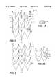
- FIG. 1is a flattened view of a stent, which would normally be formed by joining points a to a' and b to b', illustrating the sharp, angulated aspects of the stent where a series of parallel rings are used with crossties.
- FIG. 1Ais a view taken along lines A--A of FIG. 1, showing the oval cross-section of the wire-like material component.
- FIG. 2is similar to the view of FIG. 1, except the crossties have additional flexibility.
- FIG. 2Ais an alternative embodiment to FIG. 1.
- FIG. 3is a perspective view of the stent in FIG. 1, showing the additional feature of bending the angulated wire segments in a transverse plane.
- FIG. 4is an alternative to the embodiment in FIG. 3, shown in a perspective view, illustrating the use of crossties with additional flexibility.
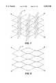
- FIG. 5is another perspective view, showing the exterior coating in the form of a mesh on the outer periphery of the stent.
- FIG. 6is yet another embodiment showing the angulated wire components with a combination of different crossties, some having more flexibility than others.
- FIG. 7is yet another embodiment illustrating the angulated wire members being out of phase as between one row and another and connected in that embodiment by crossties with flexibility.
- FIG. 8is the embodiment of FIG. 7, using crossties with less flexibility.
- FIG. 9illustrates the angulated wire components making up the stent being in alignment from one row to the next, with crossties offset circumferentially.
- FIG. 10is the view of FIG. 9, with the crossties in alignment longitudinally and circumferentially.
- FIG. 11is a close-up view of a wire prior to its being coiled into a helix as shown in FIG. 14.
- FIG. 12is an alternative embodiment to the forming of the wire in FIG. 11 as it relates to the embodiment of FIG. 14.
- FIG. 13is a sectional elevational view illustrating how the anchoring mechanism of the bend in the transverse plane operates.
- FIG. 14is an elevational view of a balloon-settable stent using the crossties having the loop feature in combination with the helically wound wire which is, itself, bent into a variety of different shapes, two of which are illustrated in FIGS. 11 and 12.
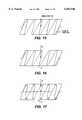
- FIG. 15illustrates a sinusoidally wound wire on a mandrel as known in the prior art.
- FIG. 16illustrates the response of such a design to a radial load.
- FIG. 17illustrates one of the embodiments of the invention involving angulated bends and a transverse bend in combination, illustrating its response to a similar load as that placed on the stent shown in FIG. 16.
- FIG. 18is a close-up of one of the elements of the stent of the present invention, illustrating one of the preferred embodiments for the cross-section as being round, as compared to the oval section shown in FIG. 1A.
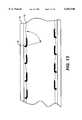
- FIG. 19illustrates a spirally wound stent employing sharp angulated bends with a transverse bend located adjacent the angulated bend and shown in a closeup inside the circle.
- FIG. 20is the stent of FIG. 19, with the crossties circumferentially offset.
- FIG. 1illustrates, in flattened form, one of the embodiments of the stent of the present invention.
- the points labeled "a" and “a'”are, in fact, joined together, as are the points "b" and "b',” to form a tubular shape for the stent.
- the stentis shown in flattened form to illustrate its components.
- the stentcan be cut from a tubular member by known techniques, such as lasers, or can be assembled from wire material.
- Wire or wire-like materialis intended to refer to the components of a stent, regardless of the manufacturing technique that is used. As illustrated in FIG. 1, wire 1 is bent in a predetermined shape and is disposed parallel to wire 4, which is in turn parallel to wire 6.
- wire 1When formed into the shape of a stent by connecting points a and a' and b and b', wire 1 is a ring made of a plurality of sharp bends 8.
- FIG. 1shows similar bends in wire 4 and 6. In this embodiment, the bends are sharp as opposed to being rounded.
- the embodiment in FIG. 1shows a general V-shape involving an apex at 10, formed by two segments 12 and 14, typically. Segments 12 and 14 can approach each other at a "sharp angle" but at a point short of the apex. They can be bent again into a near-parallel relation with a rounded apex. In this configuration, as shown in FIG.
- FIG. 2Ashows the use of U-shapes with sharp bends at apexes 16 and 18, typically.
- wire 1is secured to wire 4 by crossties such as 3, which can be of a wire material having similar or somewhat different characteristics than wires 1, 4, or 6.
- the crossties 3are relatively straight and in the same position as between wires 1 and 4 compared to wire 4 with wire 6.
- crossties such as 3can span adjacent windings or rings or can span over several, all without departing from the spirit of the invention.
- These crossties 3may be staggered such as, for example, shown in FIG. 9.
- FIG. 1Ashows the cross-section of the wire which in one embodiment is an oval, although the preferred embodiment is rounded.
- the stent depicted in FIG. 1can be assembled from wire components or can be cut from a solid tube using known laser cutting techniques.
- FIG. 2is similar to FIG. 1 except that the crossties 3 are made with a certain amount of flexibility generally put into them by a plurality of bends, although other means for providing flexibility in the crossties 3 are within the purview of the invention.
- the stentis flattened out into one plane.
- the flexible crosstiesallow greater accommodation of the stent shown in FIG. 2 when advanced into a vascular cavity that contains bends in one or more planes. To accommodate a bend, some of the crossties 3 on the inside of the bend are placed in compression and can easily compress, due to the flexibility revealed in the design of FIG.
- the crossties 3are in tension and elongate to accommodate the total stent structure in being positioned in a turn that exists in one or more planes.
- U-shapesmay be used as long as the turns or apexes 16 and 18 are "sharp" corners rather than a bending of the wire around a relatively long radius.
- the rationaleis that the sharp corners, whether in a U-shape or a V-shape, as shown in FIG. 1, when plastically deformed such as when placing the stent in position, do not recoil but instead hold their plastically deformed position much better, and therefore maintain their fixation to the vessel wall.
- FIG. 2Acan have the second bend feature, as illustrated in FIG. 19, where segments 104 and 106 are bent, raising the apexes 16 and 18 into another plane.
- the apex detail shown in FIG. 19can be used as the apex illustrated as 16 and 18 in FIG. 2A.
- the included angles in FIG. 2Amay be acute, right, or obtuse angles. Other shapes with "sharp" angles can be used such as [ or Z shapes, for example, without departing from the spirit of the invention.
- FIG. 3illustrates the use of bent wires or wire-like elements formed into rings such as, for example, 20, 22, 24, and 26. Longitudinally aligned crossties 28, 30, and 32 hold the rings to each other to create the stent structure, which is shown in perspective with its center axis labeled "x-y.”
- Each of the rings 20-26besides having the sharp bend illustrated in FIG. 1 or 2A, also has a second bend such as, for example, 34.
- the second bend 34is in a plane traversing the plane of the bends illustrated, for example, in FIG. 1 for wire 1.
- FIG. 19more readily illustrates this principle. In that figure, the sharp bends are formed, for example, in a particular segment of the stent by wire segments 36 and 38.
- FIG. 19is a continuously wound helix with ends 40 and 42 looped back around and connected at either end of the stent, as shown in the figure. This is to be distinguished from the design shown in FIG. 3 where a series of rings of wire 20-26 are employed.
- segments 36 and 38in the exploded portion of FIG. 19, it is seen that a sharp angle between them, represented by arrow 40, is formed. However, rather than connecting at an acute angle, such as shown in FIG. 1, or obtuse angles or acute angles as could be shown in FIG. 2A, segments 36 and 38 have parallel or near-parallel components 42 and 44, which are bent in a different plane than the main portion of segments 36 and 38. Eventually, the segments 42 and 44 come together at an apex 46, which in the preferred embodiment should have a small turning radius 48.
- the apex 46is outwardly oriented toward the vessel wall 50.
- the vesselhas an internal build-up 52.
- the expanded stentuses the parallel components 42 and 44, forming the apex 46, as an anchoring mechanism. While all the anchors in FIG. 13 are illustrated to be in the same orientation, some of the anchors can be in reverse orientations to other anchors, thus putting them in nonparallel planes, thereby stabilizing the stent against longitudinal movement in either direction. Such can be the case when using a design such as illustrated in FIG. 6, where a V-shaped acute angle design is illustrated. Taking the design of FIG.
- FIG. 4is similar to the embodiment of FIG. 3 except that the crossties 58 have additional flexibility in them.
- the crossties 58have additional flexibility in them.
- This structureshould be compared to a simple helical spring which, although will exhibit a tendency to have its coils come closer together on the inside of a turn and further apart on the outside, will exhibit the disadvantageous attributes of creating unduly large openings on the outside of the tum where the coils move away from each other.
- the ringssuch as 64 and 66 may move away from each other, adjacent crossties 62 and 58 will continue to bridge the gap between the rings to prevent unduly large openings in the stent which could promote significant tissue growth therethrough.
- FIG. 5illustrates the embodiment of FIG. 3, with an external covering on the stent which can be made of a biocompatible material or, in the alternative, can be coated with heparin or hydrogel. These sheath-type coatings prevent endothelial cell growth over the stent, which is a significant requirement in successful stenting of body cavities such as veins and arteries.
- FIG. 6is again a wire ring design with crossties similar to that shown in FIG. 1, except some of the wire rings have reverse orientation of their apexes, such as 54, to other rings which have their apexes pointing in the opposite direction, such as 56. While the design in FIG. 6 employs crossties such as 68, other flexible wire members 70 are placed in the transition zone 72 to fill in any large gaps in the transition zone 72. With the design of FIG. 6, the most likely flexing of the stent around a turn in a vascular flowpath will be adjacent to the transition zone 72. The wire members 70 have a plurality of bends to give them the flexibility, not only longitudinally but radially, when placing the stent of FIG. 6.
- FIG. 7illustrates the "sharp" angle design involving a generally V-shaped wire ring connected to its adjacent ring by crossties 74.
- Crossties 74have a plurality of bends, as illustrated in FIG. 7, to provide longitudinal flexibility of the stent to bend around a turn in the vascular path.
- FIG. 8is similar to FIG. 7 except that the crossties 76 are straight rather than having a plurality of bends.
- the design of FIG. 8has somewhat less flexibility with regard to being manipulatable around sharp bends but still retains additional longitudinal flexibility than prior designs.
- FIG. 9illustrates the staggering circumferentially of the crossties 78 and 80.
- crosstie 70is aligned with crosstie 82, but the ties skip a row of wires.
- crosstie 78holds together in one location wire 84 to wire 86.
- Crosstie 82is then in the same longitudinal line holding together wire rings 88 and 90. Where there is no connection between wire rings 86 and 88, aligned with crossties 78 and 82, the next crosstie appears either above or below, such as that denoted by 80, which is circumferentially offset.
- FIG. 10is similar to FIG. 9 except that the crossties are in longitudinal alignment instead of being offset circumferentially. It is clear that the design of FIG. 9 is more longitudinally flexible with respect to being workable around bends in the vascular cavities, while both designs of FIGS. 9 and 10 can flex because of their construction without twisting of the individual segments of each wire ring.
- FIGS. 11 and 12are to be considered in combination with FIG. 14.
- the wiremay be prebent in a rounded fashion, as shown in FIG. 11, or in an angled fashion, as shown in FIG. 12. These bends are very small, as can be seen in a realistic perspective by looking at FIG. 14. This design can be contrasted with the fairly large bends made in the wire such as 1 in FIG. 1.
- FIG. 14the undulations of the wire such as, for example, shown in FIGS. 11 and 12, become more readily apparent.
- a typical crosstie 92is illustrated in the exploded view.
- the stent in FIG. 14is expandable with a balloon 94.
- the crossties 92which have a loop 96 on at least one end, ride over several or at least one of the undulations represented in FIGS. 11 and 12.
- the crossties 92then remain fixated in a position representing the expanded state of the stent between a pair of undulations in a valley, such as 98. As a result, the expanded state of the stent is locked in.
- the stentmay expand as the balloon 94 grows, with loops 96 moving relatively to the undulations of the wires in each row of the helical winding 100. It should be noted that for this embodiment, crossties 92 which have loops 96 can have such loops at one end or both ends without departing from the spirit of the invention.
- FIG. 18a segment of one of the wires, which has been previously described as shown, indicates the preferred embodiment to be round.
- Wire or wire-like material as used hereinis intended to encompass a stent made literally of wires or a stent cut from a cylinder down to segments which function similarly to wires.
- FIGS. 19 and 20illustrate a helical winding for a stent, employing the sharp angled segments such as 36 and 38, but as contrasted with the design of FIG. 19, the crossties 102 are circumferentially offset in this particular case by 120°, which means that every third crosstie 102 is in longitudinal alignment. Other degrees of offset are within the purview of the invention. While straight crossties have been shown in FIGS. 19 and 20, it is within the purview of the invention to use crossties that have additional flexibility of a bend or more in them to accommodate the needs of bending for the stent.
- FIGS. 15-17illustrate some of the advantages of the use of the second bend, such as bent-up ends 42 and 44 in FIG. 19.
- FIG. 15illustrates a simple wound helix in a sinusoidal pattern, subjected to a lateral loading and illustrating in FIG. 16 the measured deflection as D.
- FIG. 17illustrates that by using sharply angled comers, in combination with the turning out in a second bend of the angled corner into a plane transversing or intersecting with the plane of the winding, again as illustrated in FIGS. 19 and 13, the net deflection is d, which is significantly less.
- the stents as above describedcan be made of a metal, such as stainless steel, platinum, nickel titanium, copper-tin alloy, or other suitable biocompatible metals.
- the stents as illustratedcan be cut from a tube whose wall thickness is between about 0.003"-0.10", using known laser techniques, so that the wire crosssection is rounded, such as illustrated in FIGS. 18 or 1A.
- the stents illustratedcan also be made from wire by bending the wire, as illustrated, to form the sharp angles as described.
- the crosstiescan be a more rigid, straight design or a more flexible design incorporating one or more bends. In lieu of a multi-ring design, a helix turned on a mandrel, using crossties, such as shown in FIG. 19, can also be employed.
- the sharp corners of the various designs indicatedprovide a uniform rigidity as well as resistance to recoil.
- the sharp angleswhen expanded by the a device such as a balloon 94 or when made from spring steel and simply pre-compressed and allowed to expand in the vascular cavity, resist recoil and tend to keep their expanded shape far better than wire bent in a rounded fashion.
- an anchoring deviceBy further bending each sharp angle into a different plane with a second bend, an anchoring device is created, plus the sharp angle itself is made far stiffer to again retain the expanded position of the stent against the wall of the vascular flowpath.
- the expanded diameter of the stents illustrated abovecan range from about 2 mm-25 mm.
- a polymeric sheath having a mesh appearancecan be attached to the outer periphery of the stent.
- This sheathcan be made from polymers such as expanded fluoropolymer, polyethylene, dacron, polyurethane, or similar materials in a thin layer.
- the polymeric layerundergoes plastic deformation. Holes or slits can be made in the plastic sheath in order to facilitate the plastic deformation and stretch of the stent to expand to its final diameter.
- the separation between each layer of strands or the pitchis between preferably 2 mm-4 mm.
- the various stents illustrated in the figurescan be delivered by a balloon such as 94 or can be made from spring steel and delivered in a compressed state with a sheath that is removed to allow the stent to spring outwardly radially for fixation. Another way to deliver such a stent is to twist it about its longitudinal axis, which results in a reduction of its outside diameter. Various clip-type devices or sleeves can then be employed to retain it in its reduced diameter state for delivery to the appropriate location in the body.
- the retraction devicesbe they clips or sleeves, can be shifted to allow the stent to take advantage of the potential energy stored in it from twisting so that it can spring out and fixate itself in the appropriate location.
- the circumferential offset of the crosstiessuch as, for example, 78 and 80 in FIG. 9, can be varied without departing from the spirit of the invention.
- the separation between crossties 78 and 80can be in the range of about 100°-180°.
- the crossties such as 78 and 80can be made from a radiopaque material to facilitate subsequent diagnostic procedures.
- the entire stentcan be made from radiopaque materials such as stainless steel or solid platinum.
- the illustrated stent designsalso facilitate application of the stent with lower inflation pressures on a balloon. Typical of known designs is the need to apply approximately 18 atmospheres of pressure to the balloon to obtain proper fixation.
- the illustrated designs of the present inventionare believed to be adequately seated at substantially lower inflation pressures for the balloon in the order of approximately 14 atmospheres.
- the illustrated designspresent the stent whose length remains relatively constant upon radial expansion. This is accomplished by flexibility in the longitudinal members which prevents the longitudinal shrinkage upon radial expansion characteristic of prior designs. It is this longitudinal shrinking upon radial expansion that has caused the segments of prior stent designs to twist into the flowpath of the stent, causing unwanted turbulence.
- the use of rounded members, such as illustrated in FIGS. 1A and 18,further helps to minimize the twist effect in conjunction with crossties that have some flexibility to them.
- the crosstiesare preferably made of "wire” having the following characteristics: The wire is normally annealed stainless steel having a diameter of 0.005"-0.010".
- the bends 8define and include an acute angle between 0°-90° with a preferred range of 15°, with the segment lengths of segments 12 and 14 being approximately 0.2 mm long and the crosstie lengths of crossties 3 being approximately 0.2 mm long.
- the apexes 16-18are again sharp angles formed by the wire, which can be acute or obtuse.
- Opposed sides 104 and 106are preferably approximately 2-3 mm long, while the connecting segment 108 between apexes 16 and 18 is preferably approximately 2 mm long.
- the preferred range of angles for the apexes 16 and 18is between 90° and 100°.
- the insertion length of crossties, such as 3 in FIG. 2, which have flexibility to them,is approximately 3 mm. When expanded to their maximum length, they are approximately 2-3 mm long in the preferred embodiment.
- each wire ring or coil of a helixhas a wire structure that has "sharp" bends as opposed to rounded bends.
- the "sharp" angular bends of the wiregive the assembled structure, be it a series of rings or a continuous helix, the rigidity to resist recoil upon expansion. In essence, once such a structure is plastically deformed, it better holds its expanded shape than a wire structure with rounded turns. By further bending the apexes into a different plane, as illustrated, for example, in FIG. 19, the tendency to hold the expanded shape is increased.
- the plane of parallel components 42 and 44 with respect to the plane of legs 36 and 38defines an included offset angle of approximately 30°. This offset is illustrated by angle A as seen in FIG. 13.
- the parallel components 42 and 44 with apex 46protrude outwardly toward the build-up 52 inside the vessel wall 50 by approximately 0.02"-0.04" in the preferred embodiment, as measured from the normal outer periphery of the expanded stent, which, for that much extension of the anchor mechanisms or apexes 46, generally has an expanded outer diameter of 0.120" to 0.200".
- FIGS. 1 and 2Another advantage of some of the designs illustrated, such as the wire ring design of FIG. 10, is that they can easily be cut down to a required size without risk of unraveling. The same can be said for the embodiment such as FIGS. 1 and 2.
- the use of the crosstiesprovides longitudinal bracing which further assists in promoting structural integrity of the stents, even if cut to a predetermined size.
- the balloon-expandable versions of the stents illustrated abovecan be made from annealed steel and expanded with a balloon.
- the embodiments using spring steel or piano wireneed to be held in a compressed state with a retractor and when positioned in the appropriate place, the retractor is relaxed and the stent is allowed to snap into place.
- bent wires having sharp anglessuch as the general V-shape of FIG. 1 and a general U-shape of FIG. 2A
- other geometric shapescan be used as long as the bent wire has sharp angles.
- the more bends per unit spacethe more flexibility to bend around turns in the vascular system the stent will have.
- the number of bends per unit spaceis increased, the ability of the stent to resist the radially inward or hoop stresses created by the vascular structure is decreased.
- the cost to manufacture the catheteris increased.
- the ability to withstand the hoop stresses imposed by the vascular structureoccurs due to the interlocking of the crosstie 92 in a valley 98 formed by a wire structure that has undulations as shown in FIGS. 11 or 12.
- Other types of undulations in the wire, along the scale necessary to lock the crosstie 92 in position after expansion with a balloon 94, or other mechanisms or devices that allow initial radial expansion to be locked in,are also within the purview of the invention.
- the structure of FIG. 14does not depend on relatively large bends above a mean baseline.
- the undulations from the average valueare fairly small but sufficiently large to allow the crosstie 92 to lodge in a valley 98.
- the undulationsmust be sufficiently small to allow the loop 96 to traverse one or more undulations as the stent expands. It is this ability of the loop 96 to traverse one or more undulations that allows the stent to be readily expanded in response to inflation of the balloon 94 and thereafter to hold its expanded position.
Landscapes
- Health & Medical Sciences (AREA)
- Engineering & Computer Science (AREA)
- Biomedical Technology (AREA)
- Cardiology (AREA)
- Oral & Maxillofacial Surgery (AREA)
- Transplantation (AREA)
- Heart & Thoracic Surgery (AREA)
- Vascular Medicine (AREA)
- Life Sciences & Earth Sciences (AREA)
- Animal Behavior & Ethology (AREA)
- General Health & Medical Sciences (AREA)
- Public Health (AREA)
- Veterinary Medicine (AREA)
- Media Introduction/Drainage Providing Device (AREA)
Abstract
Description
This application is a continuation of copending application Ser. No. 08/546,277, filed on Oct. 20, 1995.
The field of this invention relates to vascular stents that can be delivered to a predetermined position and allowed to spring outwardly or, in the alternative, which can be expanded in place.
Vascular stents are structures that are designed to maintain the patency of a vessel in the body. The stent provides internal support to allow the circulation to proceed therethrough. Stents can be used in the vascular system in ureters, bile ducts, esophagus, and in many other tubular structures in the human body.
Stents can be tubular or can be made from wire. Stents are typically made from a metal or polymeric substance or a metal coated with polymers which are biocompatible or contain heparin to reduce blood clotting or other tissue reactions. Many prior designs have used a coil approach where a wire is helically wound on a mandrel. Yet other designs have evolved--braided wire mesh and angulated wire forms wrapped on a spindle to form a coil.
U.S. Pat. No. 5,292,331 by Boneau and U.S. Pat. No. 5,403,341 describe such wire forms. These devices have very poor radial support to withstand the hoop strengths of the artery or vein and further are not suitable for arteries that are bent or curved or for long lesions; multiple stent are required. These designs do not provide any support to hold the wall of the artery, other than the memory of the metal.
Wall Stent, produced by Pfizer Inc., is a braided wire tube. Although this stent is flexible so as to be placed in curved arteries or veins and other body cavities, it does not have any radial strength imparted to it by design.
Wiktor, U.S. Pat. Nos. 4,649,922; 4,886,062; 4,969,458; and 5,133,732 describe a wire form stent. He describes stents made of wire helix made of a preformed wire which is in the sinusoidal form, in which either all or some of the adjacent strands are connected.
Arthur Fontaine, U.S. Pat. No. 5,370,683, also describes a similar device where a flat wire form of sinusoidal shape is wound on a mandrel to form a helical coil. the wire bends are "U" shaped and are connected to alternate "U"-shaped bands.
Allen Tower, U.S. Pat. Nos. 5,217,483 and 5,389,106 describes a similar device where the wire is preformed to a sinusoidal shape and subsequently wound on a mandrel to form a helical coil.
All of the above-described art fails to provide radial support. The pre-shaped wire form (sinusoidal in most of the prior art) is wrapped on a mandrel to form a coil. However, the forces imported by the vessel wall's hoop strength are radially inward. In other words, the force is acting perpendicular to the plane of the U-shaped wire form. This means that the bends that are in the wire add no structural strength to the wire form to support the force produced by the wall, which is radially inward.
When we examine the simple coils, such as taught in Scott U.S. Pat. No. 5,383,928 or Gene Samson U.S. Pat. No. 5,370,691 or Rolando Gills U.S. Pat. No. 5,222,969, it is apparent that the spring coil will withstand substantial radial forces due to the vessel wall; however, all these stents are bulky in their pre-expanded form and are hard to place in small and curved arteries or veins of the body. Also, a major disadvantage of this design is that when the coil stent is placed in a curved artery or vein, it forms an "accordion" shape whereby some strands in the outer radius are spread and those of the inner radius are gathered. Spring coils can also "flip" to form a flat structure when a longitudinal force is applied on one side of the stent.
The other types of stents that have been developed are tube stents. Palmer, U.S. Pat. Nos. 4,733,665; 4,739,762; 7,776,337; and 4,793,348 describe such a tube stent of slotted metal tube. The slotted metal tube is expanded by a high-pressure balloon to implant the stent into the inside wall of the artery or vein.
Joseph Weinstein, U.S. Pat. No. 5,213,561 describes a similar stent made of tubular materials with slots cut into it. On expansion using a balloon, it forms a structure with diamond-shaped slots.
Henry Wall, U.S. Pat. No. 5,266,073 also describes a stent, tubular, that has slots machined into it. When expanded, the edges of the stent lock to form a cylinder. Not only is this device stiff and can only be used for short lesions, but also the diameter cannot be adjusted to meet the exact needs of the particular vessel but it is fixed to the predetermined sizes.
Lau and Hastigan, U.S. Pat. No. 5,344,426 describes a slotted tubular stent that has a structure similar to Henry Wall's but has provided prongs that will lock in as the stent is expanded.
Michael Marin, U.S. Pat. No. 5,397,355 also describes a tubular slotted stent with locking prongs.
All the above-described tube stents, although typically providing substantial radial support when expanded, are not flexible enough to be placed in curved vessels. Arteries and veins in the human body are mostly curved and are tapered. As such, these tube stents suffer from this main disadvantage.
European patent document 042172982 employs wires that are doubled up and whose ends are snipped off to make a given joint. Such doubling up at the junction of two elements with snipped off free ends creates a potential puncture problem upon radial expansion. The sheer bulk of the doubled up wires makes them rotate radially outwardly away from the longitudinal centerline of the stent while the plain ends on such an arrangement which are snipped off offer the potential of sharp points which can puncture or damage the intima On the other hand, the apparatus of the present invention, employing sharp angles, as defined, avoids this problem in an embodiment which illustrates a continuous wire or wire-like member bent into a sharp angle. This type of structure alleviates the concerns of sharp edges, as well as the tendency of a doubled up heavy joint to rotate outwardly toward the intima upon radial expansion of the stem, as would be expected in the EPO reference 042172982.
Often these stents are layered with polymeric sheaths that are impregnated with biocompatible substances or can be coated with heparin or hydrogel Most sheath-type coatings reduce endothelial cell growth through the stent, which is a major requirement in successful stenting of body cavities such as arteries and veins.
Several parameters in design of stents are important. Of the more important parameters is the issue of recoil. Recoil deals with the memory of the stent material which, generally speaking, upon expansion in the blood vessel will want to recoil back to its original shape. This can be problematic because it is desirable for the stent, once expanded, to remain in good contact with the vessel wall to avoid longitudinal shifting. Furthermore, any recoil constricts the flow passage and presents a greater portion of the stent in the blood flowpath, thus creating additional complications due to the turbulence which ensues.
Related to the concern regarding recoil is another concern regarding component twist. This phenomenon generally occurs when the cross-sectional area of the components is rectangular, such as when the stent is manufactured from a cylindrical piece which is then cut by lasers or other means to form the particular pattern. Particularly in the honeycombed designs involving the use of square or rectangular element cross-sections, radial expansion of such stents generally results in a twist of the component segments such that they extend into the flowpath in the artery or vein. Again, this causes turbulence which is undesirable.
Related to the problem of recoil or constriction after expansion is the ability of the stent to anchor itself in the vascular wall. An anchoring system that does not cause trauma is a desirable feature not found in the prior art.
Yet other considerations which are desirable in a stent not found in the prior art is the flexibility to be maneuvered around bends in the vascular system, coupled with the ability to conform to a bend without kinking or leaving large open areas. The stents of the present invention have the objective of addressing the issue of recoil, as well as providing an anchoring mechanism to fixate the stent once set Several of the designs incorporate flexibility to allow the stent to follow a bend or curve in a vascular flowpath while at the same time providing sufficient radial deformation to ensure proper fixation while minimizing angular twisting movements of the stent components to minimize turbulence through the stent
A flexible stent is provided that has features to minimize recoil and facilitate anchoring of the stent in a vascular passage. The design features sharp angulated bends. Other features include a rounded cross-section in the wire or stent components. Another feature is the bending of the angulated bends in a transverse plane to provide additional rigidity and an anchoring mechanism. Ties are provided in alignment or in staggered fashion, either semi-rigid or flexible, to allow the structure, which can be made of joined rings or a helical arrangement, to be more flexible to accommodate bends in the vascular system. The ties are also disclosed with a locking system involving bending the wire which is formed into a helix in combination with crossties with loops which lock in the bends to lock the stent in an expanded position.
FIG. 1 is a flattened view of a stent, which would normally be formed by joining points a to a' and b to b', illustrating the sharp, angulated aspects of the stent where a series of parallel rings are used with crossties.
FIG. 1A is a view taken along lines A--A of FIG. 1, showing the oval cross-section of the wire-like material component.
FIG. 2 is similar to the view of FIG. 1, except the crossties have additional flexibility.
FIG. 2A is an alternative embodiment to FIG. 1.
FIG. 3 is a perspective view of the stent in FIG. 1, showing the additional feature of bending the angulated wire segments in a transverse plane.
FIG. 4 is an alternative to the embodiment in FIG. 3, shown in a perspective view, illustrating the use of crossties with additional flexibility.
FIG. 5 is another perspective view, showing the exterior coating in the form of a mesh on the outer periphery of the stent.
FIG. 6 is yet another embodiment showing the angulated wire components with a combination of different crossties, some having more flexibility than others.
FIG. 7 is yet another embodiment illustrating the angulated wire members being out of phase as between one row and another and connected in that embodiment by crossties with flexibility.
FIG. 8 is the embodiment of FIG. 7, using crossties with less flexibility.
FIG. 9 illustrates the angulated wire components making up the stent being in alignment from one row to the next, with crossties offset circumferentially.
FIG. 10 is the view of FIG. 9, with the crossties in alignment longitudinally and circumferentially.
FIG. 11 is a close-up view of a wire prior to its being coiled into a helix as shown in FIG. 14.
FIG. 12 is an alternative embodiment to the forming of the wire in FIG. 11 as it relates to the embodiment of FIG. 14.
FIG. 13 is a sectional elevational view illustrating how the anchoring mechanism of the bend in the transverse plane operates.
FIG. 14 is an elevational view of a balloon-settable stent using the crossties having the loop feature in combination with the helically wound wire which is, itself, bent into a variety of different shapes, two of which are illustrated in FIGS. 11 and 12.
FIG. 15 illustrates a sinusoidally wound wire on a mandrel as known in the prior art.
FIG. 16 illustrates the response of such a design to a radial load.
FIG. 17 illustrates one of the embodiments of the invention involving angulated bends and a transverse bend in combination, illustrating its response to a similar load as that placed on the stent shown in FIG. 16.
FIG. 18 is a close-up of one of the elements of the stent of the present invention, illustrating one of the preferred embodiments for the cross-section as being round, as compared to the oval section shown in FIG. 1A.
FIG. 19 illustrates a spirally wound stent employing sharp angulated bends with a transverse bend located adjacent the angulated bend and shown in a closeup inside the circle.
FIG. 20 is the stent of FIG. 19, with the crossties circumferentially offset.
FIG. 1 illustrates, in flattened form, one of the embodiments of the stent of the present invention. In order to form the stent, the points labeled "a" and "a'" are, in fact, joined together, as are the points "b" and "b'," to form a tubular shape for the stent. The stent is shown in flattened form to illustrate its components. The stent can be cut from a tubular member by known techniques, such as lasers, or can be assembled from wire material. Wire or wire-like material is intended to refer to the components of a stent, regardless of the manufacturing technique that is used. As illustrated in FIG. 1,wire 1 is bent in a predetermined shape and is disposed parallel towire 4, which is in turn parallel towire 6. When formed into the shape of a stent by connecting points a and a' and b and b',wire 1 is a ring made of a plurality ofsharp bends 8. FIG. 1 shows similar bends inwire segments Segments apexes
Referring again to FIG. 1,wire 1 is secured towire 4 by crossties such as 3, which can be of a wire material having similar or somewhat different characteristics thanwires crossties 3 are relatively straight and in the same position as betweenwires wire 4 withwire 6. In all the embodiments, crossties such as 3 can span adjacent windings or rings or can span over several, all without departing from the spirit of the invention. Thesecrossties 3 may be staggered such as, for example, shown in FIG. 9. FIG. 1A shows the cross-section of the wire which in one embodiment is an oval, although the preferred embodiment is rounded.
Usage of rings (see FIG. 1) or a continuous member (see FIG. 19) turned in a helical manner are each considered to be structures that employ "windings."
The stent depicted in FIG. 1 can be assembled from wire components or can be cut from a solid tube using known laser cutting techniques. FIG. 2 is similar to FIG. 1 except that thecrossties 3 are made with a certain amount of flexibility generally put into them by a plurality of bends, although other means for providing flexibility in thecrossties 3 are within the purview of the invention. Again, in the view of FIG. 2, the stent is flattened out into one plane. The flexible crossties allow greater accommodation of the stent shown in FIG. 2 when advanced into a vascular cavity that contains bends in one or more planes. To accommodate a bend, some of thecrossties 3 on the inside of the bend are placed in compression and can easily compress, due to the flexibility revealed in the design of FIG. 2, while on the opposite side of the bend, thecrossties 3 are in tension and elongate to accommodate the total stent structure in being positioned in a turn that exists in one or more planes. As previously stated, U-shapes may be used as long as the turns or apexes 16 and 18 are "sharp" corners rather than a bending of the wire around a relatively long radius. The rationale is that the sharp corners, whether in a U-shape or a V-shape, as shown in FIG. 1, when plastically deformed such as when placing the stent in position, do not recoil but instead hold their plastically deformed position much better, and therefore maintain their fixation to the vessel wall. In combination with the crossties in FIGS. 1 or 2 that have some flexibility, bends of various degrees of sharpness can be traversed by the stent without kinking. The design in FIG. 2A can have the second bend feature, as illustrated in FIG. 19, wheresegments apexes
FIG. 3 illustrates the use of bent wires or wire-like elements formed into rings such as, for example, 20, 22, 24, and 26. Longitudinally alignedcrossties second bend 34 is in a plane traversing the plane of the bends illustrated, for example, in FIG. 1 forwire 1. FIG. 19 more readily illustrates this principle. In that figure, the sharp bends are formed, for example, in a particular segment of the stent bywire segments
Looking now at thesegments segments parallel components segments segments small turning radius 48.
As seen in FIG. 13, the apex 46 is outwardly oriented toward thevessel wall 50. Typically, the vessel has an internal build-up 52. The expanded stent, as shown in FIG. 13, uses theparallel components apex 56 is also turned outwardly, then an anchoring system would be employed where some of the extending segments, as shown in FIG. 19, would be oriented in the direction shown in FIG. 13, while others would have the opposite orientation.
The embodiment shown in FIG. 4 is similar to the embodiment of FIG. 3 except that thecrossties 58 have additional flexibility in them. Thus, for example, if the stent of FIG. 4 were placed into a turn in a vascular structure, where the inside of the turn is represented bycrossties 60, those crossties would tend to compress while the outside of the turn, represented bycrossties adjacent crossties
FIG. 5 illustrates the embodiment of FIG. 3, with an external covering on the stent which can be made of a biocompatible material or, in the alternative, can be coated with heparin or hydrogel. These sheath-type coatings prevent endothelial cell growth over the stent, which is a significant requirement in successful stenting of body cavities such as veins and arteries.
The embodiment shown in FIG. 6 is again a wire ring design with crossties similar to that shown in FIG. 1, except some of the wire rings have reverse orientation of their apexes, such as 54, to other rings which have their apexes pointing in the opposite direction, such as 56. While the design in FIG. 6 employs crossties such as 68, otherflexible wire members 70 are placed in thetransition zone 72 to fill in any large gaps in thetransition zone 72. With the design of FIG. 6, the most likely flexing of the stent around a turn in a vascular flowpath will be adjacent to thetransition zone 72. Thewire members 70 have a plurality of bends to give them the flexibility, not only longitudinally but radially, when placing the stent of FIG. 6.
FIG. 7 illustrates the "sharp" angle design involving a generally V-shaped wire ring connected to its adjacent ring bycrossties 74.Crossties 74 have a plurality of bends, as illustrated in FIG. 7, to provide longitudinal flexibility of the stent to bend around a turn in the vascular path.
FIG. 8 is similar to FIG. 7 except that thecrossties 76 are straight rather than having a plurality of bends. The design of FIG. 8 has somewhat less flexibility with regard to being manipulatable around sharp bends but still retains additional longitudinal flexibility than prior designs.
FIG. 9 illustrates the staggering circumferentially of thecrossties crosstie 70 is aligned withcrosstie 82, but the ties skip a row of wires. Accordingly,crosstie 78 holds together in onelocation wire 84 towire 86. In that same longitudinal line, there is a gap with no crosstie betweenwire ring 86 andwire ring 88.Crosstie 82 is then in the same longitudinal line holding together wire rings 88 and 90. Where there is no connection between wire rings 86 and 88, aligned withcrossties
FIG. 10 is similar to FIG. 9 except that the crossties are in longitudinal alignment instead of being offset circumferentially. It is clear that the design of FIG. 9 is more longitudinally flexible with respect to being workable around bends in the vascular cavities, while both designs of FIGS. 9 and 10 can flex because of their construction without twisting of the individual segments of each wire ring.
FIGS. 11 and 12 are to be considered in combination with FIG. 14. In this embodiment, the wire may be prebent in a rounded fashion, as shown in FIG. 11, or in an angled fashion, as shown in FIG. 12. These bends are very small, as can be seen in a realistic perspective by looking at FIG. 14. This design can be contrasted with the fairly large bends made in the wire such as 1 in FIG. 1.
In the design of FIG. 14, the undulations of the wire such as, for example, shown in FIGS. 11 and 12, become more readily apparent. In FIG. 14, atypical crosstie 92 is illustrated in the exploded view. The stent in FIG. 14 is expandable with aballoon 94. As the stent grows radially when theballoon 94 is expanded, thecrossties 92, which have aloop 96 on at least one end, ride over several or at least one of the undulations represented in FIGS. 11 and 12. Thecrossties 92 then remain fixated in a position representing the expanded state of the stent between a pair of undulations in a valley, such as 98. As a result, the expanded state of the stent is locked in. The stent may expand as theballoon 94 grows, withloops 96 moving relatively to the undulations of the wires in each row of the helical winding 100. It should be noted that for this embodiment,crossties 92 which haveloops 96 can have such loops at one end or both ends without departing from the spirit of the invention.
Referring now to FIG. 18, a segment of one of the wires, which has been previously described as shown, indicates the preferred embodiment to be round. The use of a rounded cross-section, such as shown in FIGS. 1A or 18, prevents kinking of the wire segments upon expansion of the stent. Prior designs which have used square or rectangular cross-sections, resulting from using laser cutting techniques and cutting out wire segments from a solid cylinder, have exhibited a tendency of twist such that the wire rings or the helix contain kinks which stick into the flowpath, causing undesirable turbulence. Wire or wire-like material as used herein is intended to encompass a stent made literally of wires or a stent cut from a cylinder down to segments which function similarly to wires.
FIGS. 19 and 20 illustrate a helical winding for a stent, employing the sharp angled segments such as 36 and 38, but as contrasted with the design of FIG. 19, thecrossties 102 are circumferentially offset in this particular case by 120°, which means that everythird crosstie 102 is in longitudinal alignment. Other degrees of offset are within the purview of the invention. While straight crossties have been shown in FIGS. 19 and 20, it is within the purview of the invention to use crossties that have additional flexibility of a bend or more in them to accommodate the needs of bending for the stent.
FIGS. 15-17 illustrate some of the advantages of the use of the second bend, such as bent-up ends 42 and 44 in FIG. 19. FIG. 15 illustrates a simple wound helix in a sinusoidal pattern, subjected to a lateral loading and illustrating in FIG. 16 the measured deflection as D. FIG. 17 illustrates that by using sharply angled comers, in combination with the turning out in a second bend of the angled corner into a plane transversing or intersecting with the plane of the winding, again as illustrated in FIGS. 19 and 13, the net deflection is d, which is significantly less.
This illustration brings to the fore several salient advantages of the various embodiments previously described.
The stents as above described can be made of a metal, such as stainless steel, platinum, nickel titanium, copper-tin alloy, or other suitable biocompatible metals. The stents as illustrated can be cut from a tube whose wall thickness is between about 0.003"-0.10", using known laser techniques, so that the wire crosssection is rounded, such as illustrated in FIGS. 18 or 1A. The stents illustrated can also be made from wire by bending the wire, as illustrated, to form the sharp angles as described. The crossties can be a more rigid, straight design or a more flexible design incorporating one or more bends. In lieu of a multi-ring design, a helix turned on a mandrel, using crossties, such as shown in FIG. 19, can also be employed.
The sharp corners of the various designs indicated provide a uniform rigidity as well as resistance to recoil. The sharp angles, when expanded by the a device such as aballoon 94 or when made from spring steel and simply pre-compressed and allowed to expand in the vascular cavity, resist recoil and tend to keep their expanded shape far better than wire bent in a rounded fashion. By further bending each sharp angle into a different plane with a second bend, an anchoring device is created, plus the sharp angle itself is made far stiffer to again retain the expanded position of the stent against the wall of the vascular flowpath.
The expanded diameter of the stents illustrated above can range from about 2 mm-25 mm. As illustrated in FIG. 5, a polymeric sheath having a mesh appearance can be attached to the outer periphery of the stent. This sheath can be made from polymers such as expanded fluoropolymer, polyethylene, dacron, polyurethane, or similar materials in a thin layer. During expansion, the polymeric layer undergoes plastic deformation. Holes or slits can be made in the plastic sheath in order to facilitate the plastic deformation and stretch of the stent to expand to its final diameter.
In the embodiment such as shown in FIG. 14, the separation between each layer of strands or the pitch is between preferably 2 mm-4 mm. The various stents illustrated in the figures can be delivered by a balloon such as 94 or can be made from spring steel and delivered in a compressed state with a sheath that is removed to allow the stent to spring outwardly radially for fixation. Another way to deliver such a stent is to twist it about its longitudinal axis, which results in a reduction of its outside diameter. Various clip-type devices or sleeves can then be employed to retain it in its reduced diameter state for delivery to the appropriate location in the body. At this time the retraction devices, be they clips or sleeves, can be shifted to allow the stent to take advantage of the potential energy stored in it from twisting so that it can spring out and fixate itself in the appropriate location. The circumferential offset of the crossties such as, for example, 78 and 80 in FIG. 9, can be varied without departing from the spirit of the invention. Typically, measuring from the longitudinal axis of a stent, the separation betweencrossties
The illustrated stent designs also facilitate application of the stent with lower inflation pressures on a balloon. Typical of known designs is the need to apply approximately 18 atmospheres of pressure to the balloon to obtain proper fixation. The illustrated designs of the present invention are believed to be adequately seated at substantially lower inflation pressures for the balloon in the order of approximately 14 atmospheres.
The illustrated designs present the stent whose length remains relatively constant upon radial expansion. This is accomplished by flexibility in the longitudinal members which prevents the longitudinal shrinkage upon radial expansion characteristic of prior designs. It is this longitudinal shrinking upon radial expansion that has caused the segments of prior stent designs to twist into the flowpath of the stent, causing unwanted turbulence. The use of rounded members, such as illustrated in FIGS. 1A and 18, further helps to minimize the twist effect in conjunction with crossties that have some flexibility to them. In the preferred embodiment of FIGS. 2, 2a, 6, and 7, the crossties are preferably made of "wire" having the following characteristics: The wire is normally annealed stainless steel having a diameter of 0.005"-0.010".
In the embodiment illustrated in FIG. 1, thebends 8 define and include an acute angle between 0°-90° with a preferred range of 15°, with the segment lengths ofsegments crossties 3 being approximately 0.2 mm long. In the embodiment shown in FIG. 2A, the apexes 16-18 are again sharp angles formed by the wire, which can be acute or obtuse.Opposed sides segment 108 betweenapexes apexes
Again it should be noted that in the embodiments illustrated in FIGS. 1-10, 13, and 19-20, it is preferred that each wire ring or coil of a helix has a wire structure that has "sharp" bends as opposed to rounded bends. The "sharp" angular bends of the wire give the assembled structure, be it a series of rings or a continuous helix, the rigidity to resist recoil upon expansion. In essence, once such a structure is plastically deformed, it better holds its expanded shape than a wire structure with rounded turns. By further bending the apexes into a different plane, as illustrated, for example, in FIG. 19, the tendency to hold the expanded shape is increased. In the preferred embodiment, the plane ofparallel components legs parallel components apex 46 protrude outwardly toward the build-up 52 inside thevessel wall 50 by approximately 0.02"-0.04" in the preferred embodiment, as measured from the normal outer periphery of the expanded stent, which, for that much extension of the anchor mechanisms or apexes 46, generally has an expanded outer diameter of 0.120" to 0.200".
Another advantage of some of the designs illustrated, such as the wire ring design of FIG. 10, is that they can easily be cut down to a required size without risk of unraveling. The same can be said for the embodiment such as FIGS. 1 and 2. The use of the crossties provides longitudinal bracing which further assists in promoting structural integrity of the stents, even if cut to a predetermined size. As opposed to using spring steel, the balloon-expandable versions of the stents illustrated above can be made from annealed steel and expanded with a balloon. The embodiments using spring steel or piano wire need to be held in a compressed state with a retractor and when positioned in the appropriate place, the retractor is relaxed and the stent is allowed to snap into place.
It should be noted that while certain configurations of bent wires having sharp angles have been illustrated, such as the general V-shape of FIG. 1 and a general U-shape of FIG. 2A, other geometric shapes can be used as long as the bent wire has sharp angles. The more bends per unit space, the more flexibility to bend around turns in the vascular system the stent will have. However, as the number of bends per unit space is increased, the ability of the stent to resist the radially inward or hoop stresses created by the vascular structure is decreased. Additionally, as more bends are employed, the cost to manufacture the catheter is increased.
It should be noted that with the embodiment of FIG. 14, the ability to withstand the hoop stresses imposed by the vascular structure occurs due to the interlocking of thecrosstie 92 in a valley 98 formed by a wire structure that has undulations as shown in FIGS. 11 or 12. Other types of undulations in the wire, along the scale necessary to lock thecrosstie 92 in position after expansion with aballoon 94, or other mechanisms or devices that allow initial radial expansion to be locked in, are also within the purview of the invention.
The structure of FIG. 14 does not depend on relatively large bends above a mean baseline. When looking at the design of FIG. 14, the undulations from the average value are fairly small but sufficiently large to allow thecrosstie 92 to lodge in a valley 98. The undulations must be sufficiently small to allow theloop 96 to traverse one or more undulations as the stent expands. It is this ability of theloop 96 to traverse one or more undulations that allows the stent to be readily expanded in response to inflation of theballoon 94 and thereafter to hold its expanded position.
The foregoing disclosure and description of the invention are illustrative and explanatory thereof, and various changes in the size, shape and materials, as well as in the details of the illustrated construction, may be made without departing from the spirit of the invention.
Claims (32)
1. A stent comprising:
a radially flexible tubular structure made from a plurality of windings comprising peaks and valleys of a wire-like material about a longitudinal axis;
said wire-like material incorporating sharp first bends formed by at least two of segments of said wire-like material approaching each other for substantially their entire length;
said segments meeting at a point or becoming parallel to each other immediately before being joined;
at least one crosstie extending generally longitudinally to connect at least one of said windings to another of said windings; and
said sharp first bends, expanded beyond the original diameter, to resist recoil of the stent toward its original diameter.
2. A stent comprising:
a radially flexible tubular structure made from a plurality of windings comprising peaks and valleys of a wire-like material about a longitudinal axis;
said wire-like material incorporating sharp first bends formed by at least two of segments of said wire-like material approaching each other for substantially their entire length;
said segments meeting at a point or becoming parallel to each other immediately before being joined;
at least one crosstie extending generally longitudinally to connect at least one of said windings to another of said windings;
said at least one crosstie is formed to be flexible to change its length in response to a bending force applied to said tubular structure;
said sharp first bends, when plastically expanded beyond the original diameter, to resist recoil of the stent toward its original diameter.
3. The stent of claim 1, further comprising:
at least one second bend formed adjacent said first bends, said first bends disposing said wire-like material in a first plane while said second bend alters at least one of said sharp first bends out of said first plane and into an intersecting plane where an apex is formed.
4. The stent of claim 3, wherein said second bend turns said apex outwardly away from the longitudinal axis of said tubular structure.
5. The stent of claim 4, further comprising a plurality of second bends wherein some of said second bends are in planes not parallel to other second bends.
6. The stent of claim 1, wherein some of said sharp first bends are oppositely oriented with respect to said sharp first bends on other windings.
7. A stent comprising:
a radially flexible tubular structure made from a plurality of windings comprising peaks and valleys of a wire-like material about a longitudinal axis;
said wire-like material incorporating sharp first bends formed by at least two of segments of said wire-like material approaching each other for substantially their entire length;
said segments meeting at a point or becoming parallel to each other immediately before being joined;
at least one crosstie extending generally longitudinally to connect at least one of said windings to another of said windings;
said sharp first bends, expanded beyond the original diameter, to resist recoil of the stent toward its original diameter; and
at least some of said sharp first bends are similarly oriented between adjacent windings but are circumferentially out of phase with other sharp first bends on an adjacent winding.
8. The stent of claim 1, wherein at least some of said sharp first bends are similarly oriented between adjacent windings but are circumferentially in phase with other sharp first bends on an adjacent winding.
9. The stent of claim 7, wherein said at least one crosstie is formed to be flexible to change its length in response to a bending force applied to said tubular structure.
10. The stent of claim 8, wherein said at least one crosstie is formed to be flexible to change its length in response to a bending force applied to said tubular structure.
11. The stent of claim 7, further comprising a plurality of crossties wherein at least one of said crossfies between a first winding and a second winding is circumferentially misaligned from said crossties which extend between said second winding and a third winding.
12. The stent of claim 8, further comprising a plurality of crossties wherein at least one of said crossties between a first winding and a second winding is circumferentially misaligned from said crossfies which extend between said second winding and a third winding.
13. The stent of claim 3, wherein said second bend is disposed on each of said segments prior to said apex, with said sharp first bend defined by said approaching segments up to said second bend, said segments beyond said second bend coming together to define a rounded configuration of said apex.
14. The stent of claim 13, wherein at least one said second bend turns said apex outwardly away from the longitudinal axis of said tubular structure.
15. The stent of claim 14, wherein each apex is turned away from said longitudinal axis obliquely to said sharp first bend.
16. The stent of claim 15, further comprising a plurality of second bends wherein said second bends are disposed in intersecting planes.
17. The stent of claim 13, wherein said at least one crosstie is flexible to change its length in response to a bending force applied to said tubular structure.
18. The stent of claim 13, wherein at least some of said sharp first bends are similarly oriented between adjacent windings but are circumferentially out of phase with other sharp first bends on an adjacent winding.
19. The stent of claim 13, wherein at least some of said sharp first bends are similarly oriented between adjacent windings but are circumferentially in phase with other sharp first bends on an adjacent winding.
20. The stent of claim 1, wherein said wire-like material has at least a partially rounded cross-section.
21. The stent of claim 20, wherein said wire-like material is formed of a metal which gives the stent a characteristic of a spring when formed into a tubular structure.
22. The stent of claim 20, wherein said wire-like material is formed of an annealed metal which must be mechanically expanded for use of the stent.
23. The stent of claim 1, wherein said tubular structure is formed from discrete rings of said wire-like material, secured to each other by a plurality of crossties.
24. A stent comprising:
a radially flexible tubular structure made from a plurality of windings comprising peaks and valleys of a wire-like material about a longitudinal axis;
said wire-like material incorporating sharp first bends formed by at least two of segments of said wire-like material approaching each other for substantially their entire length;
said segments meeting at a point or becoming parallel to each other immediately before being joined;
at least one crosstie extending generally longitudinally to connect at least one of said windings to another of said windings;
said sharp first bends, expanded beyond the original diameter, to resist recoil of the stent toward its original diameter; and
said tubular structure is formed from a continuous spirally wound wire-like material where a plurality of said crossfies connect said windings.
25. The stent of claim 2, wherein said tubular structure is formed from discrete rings of said wire-like material, secured to each other by a plurality of crossties.
26. The stent of claim 2, wherein said tubular structure is formed from a continuous spirally wound wire-like material and further comprises a plurality of crossties which connect said windings.
27. The stent of claim 3, wherein said tubular structure is formed from discrete rings of said wire-like material, secured to each other by a plurality of crossties.
28. The stent of claim 3, wherein said tubular structure is formed from a continuous spirally wound wire-like material and further comprises a plurality of crossties which connect said windings.
29. A stent, comprising:
a radially flexible tubular structure made from a plurality of windings about a longitudinal axis of an undulating wire-like material, incorporating a plurality of undulations along its length; and
at least one crosstie spanning a pair of said windings and forming a loop over said undulations thereby permitting relative unidirectional movement between said loop and differing undulations on at least one of said windings which are thereby engaged.
30. The stent of claim 29, wherein:
said at least one crosstie is formed having a loop extending around said undulating wire-like material at said end thereof;
said plurality of windings are radially expandable, facilitated by said relative movement as said loop allows movement therethrough of said undulating wire-like element, whereupon attaining the desired radial expansion of said windings, said loop is retained between said undulations to minimize recoil.
31. The stent of claim 30, wherein said undulations are formed with angled bends.
32. The stent of claim 30, wherein said undulations are formed with rounded bends.
Priority Applications (1)
| Application Number | Priority Date | Filing Date | Title |
|---|---|---|---|
| US08/955,458US6053940A (en) | 1995-10-20 | 1997-10-21 | Vascular stent |
Applications Claiming Priority (2)
| Application Number | Priority Date | Filing Date | Title |
|---|---|---|---|
| US54627795A | 1995-10-20 | 1995-10-20 | |
| US08/955,458US6053940A (en) | 1995-10-20 | 1997-10-21 | Vascular stent |
Related Parent Applications (1)
| Application Number | Title | Priority Date | Filing Date |
|---|---|---|---|
| US54627795AContinuation | 1995-10-20 | 1995-10-20 |
Publications (1)
| Publication Number | Publication Date |
|---|---|
| US6053940Atrue US6053940A (en) | 2000-04-25 |
Family
ID=24179668
Family Applications (1)
| Application Number | Title | Priority Date | Filing Date |
|---|---|---|---|
| US08/955,458Expired - Fee RelatedUS6053940A (en) | 1995-10-20 | 1997-10-21 | Vascular stent |
Country Status (3)
| Country | Link |
|---|---|
| US (1) | US6053940A (en) |
| AU (1) | AU7458596A (en) |
| WO (1) | WO1997014375A1 (en) |
Cited By (150)
| Publication number | Priority date | Publication date | Assignee | Title |
|---|---|---|---|---|
| US6200337B1 (en)* | 1996-03-10 | 2001-03-13 | Terumo Kabushiki Kaisha | Implanting stent |
| US20020042645A1 (en)* | 1996-07-03 | 2002-04-11 | Shannon Donald T. | Drug eluting radially expandable tubular stented grafts |
| US20020049493A1 (en)* | 1996-04-26 | 2002-04-25 | Jang G. David | Intravascular stent |
| US6428570B1 (en)* | 1995-10-16 | 2002-08-06 | Medtronic, Inc. | Medical stents, apparatus and method for making same |
| US20020138131A1 (en)* | 2001-03-20 | 2002-09-26 | Solovay Kenneth S. | Rail stent |
| US20020143390A1 (en)* | 2001-03-30 | 2002-10-03 | Tatsuzo Ishii | Stent |
| US6461380B1 (en) | 1998-07-28 | 2002-10-08 | Advanced Cardiovascular Systems, Inc. | Stent configuration |
| US20020151962A1 (en)* | 1997-10-09 | 2002-10-17 | Scimed Life Systems, Inc. | Stent configurations |
| US20020161429A1 (en)* | 1996-04-26 | 2002-10-31 | Jang G. David | Intravascular stent |
| US20020169500A1 (en)* | 1996-04-26 | 2002-11-14 | Jang G. David | Intravascular stent |
| US6500204B1 (en)* | 1998-09-08 | 2002-12-31 | Kabushikikaisha Igaki Iryo Sekkei | Stent for vessels |
| US20030055489A1 (en)* | 1998-07-08 | 2003-03-20 | Scimed Life Systems, Inc. | Stent |
| US6563080B2 (en)* | 2001-02-15 | 2003-05-13 | Scimed Life Systems, Inc. | Laser cutting of stents and other medical devices |
| US20030093144A1 (en)* | 1998-02-02 | 2003-05-15 | Scimed Life Systems, Inc. | Tubular stent consists of chevron-shape expansion struts and contralaterally attached diagonal-connectors |
| US6585753B2 (en)* | 2001-03-28 | 2003-07-01 | Scimed Life Systems, Inc. | Expandable coil stent |
| WO2003070125A1 (en)* | 2001-12-21 | 2003-08-28 | Cardiovasc, Inc. | Composite stent with polymeric covering and bioactive coating |
| US6616689B1 (en) | 2000-05-03 | 2003-09-09 | Advanced Cardiovascular Systems, Inc. | Intravascular stent |
| US20030177949A1 (en)* | 2000-03-31 | 2003-09-25 | Flex Products, Inc. | Methods for producing enhanced interference pigments |
| US6629994B2 (en) | 2001-06-11 | 2003-10-07 | Advanced Cardiovascular Systems, Inc. | Intravascular stent |
| US6635083B1 (en) | 2001-06-25 | 2003-10-21 | Advanced Cardiovascular Systems, Inc. | Stent with non-linear links and method of use |
| US6656220B1 (en) | 2002-06-17 | 2003-12-02 | Advanced Cardiovascular Systems, Inc. | Intravascular stent |
| US20040093073A1 (en)* | 2002-05-08 | 2004-05-13 | David Lowe | Endoprosthesis having foot extensions |
| US20040093072A1 (en)* | 2002-05-06 | 2004-05-13 | Jeff Pappas | Endoprosthesis for controlled contraction and expansion |
| US20040106980A1 (en)* | 2002-08-15 | 2004-06-03 | Gmp Cardiac Care, Inc. | Stent-graft with rails |
| US20040106975A1 (en)* | 2001-03-20 | 2004-06-03 | Gmp/Cardiac Care, Inc. | Rail stent |
| US20040106985A1 (en)* | 1996-04-26 | 2004-06-03 | Jang G. David | Intravascular stent |
| US6749629B1 (en) | 2001-06-27 | 2004-06-15 | Advanced Cardiovascular Systems, Inc. | Stent pattern with figure-eights |
| US6758860B1 (en)* | 1996-03-05 | 2004-07-06 | Envysio Medical Devices Ulc | Expandable stent and method for delivery of same |
| US20040133271A1 (en)* | 2000-09-22 | 2004-07-08 | Jang G. David | Intravascular stent and assembly |
| US20040148011A1 (en)* | 2003-01-24 | 2004-07-29 | Brian Shiu | Flexible connecting bar for an endoluminal stent graft |
| US20040153141A1 (en)* | 1996-03-05 | 2004-08-05 | Penn Ian M. | Expandable stent and method for delivery of same |
| US20040181186A1 (en)* | 2003-03-13 | 2004-09-16 | Scimed Life Systems, Inc. | Medical device |
| US6796997B1 (en) | 1996-03-05 | 2004-09-28 | Evysio Medical Devices Ulc | Expandable stent |
| US20040193178A1 (en)* | 2003-03-26 | 2004-09-30 | Cardiomind, Inc. | Multiple joint implant delivery systems for sequentially-controlled implant deployment |
| US6805704B1 (en) | 2000-06-26 | 2004-10-19 | C. R. Bard, Inc. | Intraluminal stents |
| US20040215326A1 (en)* | 2003-04-22 | 2004-10-28 | Goodson Harry B. | Single-piece crown stent |
| US6846323B2 (en) | 2003-05-15 | 2005-01-25 | Advanced Cardiovascular Systems, Inc. | Intravascular stent |
| US20050056292A1 (en)* | 1999-08-05 | 2005-03-17 | Cooper Joel D. | Devices for maintaining patency of surgically created channels in tissue |
| US20050107865A1 (en)* | 2003-05-06 | 2005-05-19 | Anton Clifford | Endoprosthesis having foot extensions |
| US20050159807A1 (en)* | 2002-08-30 | 2005-07-21 | Bales Thomas O. | Helical stent having improved flexibility and expandability |
| US6929660B1 (en) | 2000-12-22 | 2005-08-16 | Advanced Cardiovascular Systems, Inc. | Intravascular stent |
| US20060015173A1 (en)* | 2003-05-06 | 2006-01-19 | Anton Clifford | Endoprosthesis having foot extensions |
| US20060069400A1 (en)* | 2004-09-27 | 2006-03-30 | Theranova, Llc | Method and apparatus for anchoring implants |
| US20060079955A1 (en)* | 2004-10-07 | 2006-04-13 | Scimed Life Systems, Inc. | Non-shortening helical stent |
| US20060116749A1 (en)* | 2003-07-18 | 2006-06-01 | Broncus Technologies, Inc. | Devices for maintaining patency of surgically created channels in tissue |
| JP2006521187A (en)* | 2003-03-25 | 2006-09-21 | マイクロ ベンション インコーポレイテッド | Methods and apparatus for treating aneurysms and other vascular disorders |
| US20070021834A1 (en)* | 2003-05-06 | 2007-01-25 | Eugene Young | Endoprosthesis having foot extensions |
| US20070021826A1 (en)* | 2003-04-24 | 2007-01-25 | Cook Incorporated | Intralumenally implantable frames |
| US20070038291A1 (en)* | 2003-04-24 | 2007-02-15 | Cook Incorporated | Intralumenally-implantable frames |
| US7179286B2 (en) | 2003-02-21 | 2007-02-20 | Boston Scientific Scimed, Inc. | Stent with stepped connectors |
| US20070100435A1 (en)* | 2003-04-24 | 2007-05-03 | Cook Incorporated | Artificial prostheses with preferred geometries |
| US20070191926A1 (en)* | 2006-02-14 | 2007-08-16 | Advanced Cardiovascular Systems, Inc. | Stent pattern for high stent retention |
| WO2007095466A2 (en) | 2006-02-14 | 2007-08-23 | Angiomed Gmbh & Co. Medizintechnik Kg | Highly flexible stent and method of manufacture |
| US20070255304A1 (en)* | 2002-02-21 | 2007-11-01 | Roschak Edmund J | Devices for creating passages and sensing for blood vessels |
| US20070260327A1 (en)* | 2003-04-24 | 2007-11-08 | Case Brian C | Artificial Valve Prosthesis with Improved Flow Dynamics |
| US20080009664A1 (en)* | 2006-07-10 | 2008-01-10 | Michelle Bartning | Method of treating urinary incontinence |
| US20080033230A1 (en)* | 2006-07-10 | 2008-02-07 | Michelle Bartning | Resilient device |
| US20080086194A1 (en)* | 2006-10-06 | 2008-04-10 | Advanced Cardiovascular Systems, | Intravascular stent |
| WO2008100783A2 (en) | 2007-02-12 | 2008-08-21 | C.R. Bard Inc. | Highly flexible stent and method of manufacture |
| US20080281406A1 (en)* | 1997-06-13 | 2008-11-13 | Orbusneich Medical, Inc. | Stent having helical elements |
| US20090030435A1 (en)* | 2004-09-27 | 2009-01-29 | Theranova, Llc | Method and apparatus for anchoring cardiovascular implants |
| WO2007083305A3 (en)* | 2006-01-17 | 2009-04-30 | Ez Surgical Ltd | Access enabling device for surgical procedures |
| US20090192589A1 (en)* | 2001-06-11 | 2009-07-30 | Advanced Cardiovascular Systems, Inc. | Intravascular stent |
| US20090204201A1 (en)* | 2006-05-18 | 2009-08-13 | C. R. Bard, Inc. | Bend-capable stent prosthesis |
| US20090216314A1 (en)* | 2005-11-10 | 2009-08-27 | Arshad Quadri | Balloon-Expandable, Self-Expanding, Vascular Prosthesis Connecting Stent |
| US20090306768A1 (en)* | 2006-07-28 | 2009-12-10 | Cardiaq Valve Technologies, Inc. | Percutaneous valve prosthesis and system and method for implanting same |
| US7637936B2 (en) | 2001-04-06 | 2009-12-29 | Boston Scientific Scimed, Inc. | Stent design |
| US20100004725A1 (en)* | 2006-09-07 | 2010-01-07 | C. R. Bard, Inc. | Helical implant having different ends |
| US20100016949A1 (en)* | 2006-08-29 | 2010-01-21 | C.R.Bard, Inc. | Annular mesh |
| US20100070021A1 (en)* | 2006-12-06 | 2010-03-18 | C.R. Bard, Inc | Stenting Ring with Marker |
| US20100082094A1 (en)* | 2008-09-29 | 2010-04-01 | Arshad Quadri | Heart valve |
| US20100082089A1 (en)* | 2008-10-01 | 2010-04-01 | Arshad Quadri | Delivery system for vascular implant |
| US20100191321A1 (en)* | 2007-09-07 | 2010-07-29 | C.R. Bard ,Inc. | Self-expansible stent with radiopaque markers and method of making such a stent |
| US7771463B2 (en)* | 2003-03-26 | 2010-08-10 | Ton Dai T | Twist-down implant delivery technologies |
| US20100211161A1 (en)* | 2007-04-03 | 2010-08-19 | C. R. Bard, Inc. | Bendable Stent |
| US7785361B2 (en) | 2003-03-26 | 2010-08-31 | Julian Nikolchev | Implant delivery technologies |
| US20100218359A1 (en)* | 2006-07-10 | 2010-09-02 | Michelle Bartning | Resilient device |
| US20100234936A1 (en)* | 2006-08-21 | 2010-09-16 | Martin Schlun | Self-expanding stent |
| US20100249903A1 (en)* | 2006-11-10 | 2010-09-30 | C. R. Bard, Inc. | Stent |
| US20100256607A1 (en)* | 2007-08-15 | 2010-10-07 | Daniel Rogers Burnett | Method and apparatus for automated active sterilization of fully implanted devices |
| US20100298921A1 (en)* | 2006-05-17 | 2010-11-25 | C. R. Bard, Inc. | Bend-capable tubular prosthesis |
| US7862602B2 (en) | 2005-11-02 | 2011-01-04 | Biosensors International Group, Ltd | Indirect-release electrolytic implant delivery systems |
| US20110004299A1 (en)* | 2006-02-18 | 2011-01-06 | The Cleveland Clinic Foundation | Apparatus and method for replacing a diseased cardiac valve |
| US20110004290A1 (en)* | 2007-02-12 | 2011-01-06 | C.R. Bard, Inc. | Highly flexible stent and method of manufacture |
| US20110015721A1 (en)* | 1998-03-05 | 2011-01-20 | Boston Scientific Scimed, Inc. | Intraluminal Stent |
| US20110152604A1 (en)* | 2009-12-23 | 2011-06-23 | Hull Jr Raymond J | Intravaginal incontinence device |
| US20110166640A1 (en)* | 2008-09-02 | 2011-07-07 | Cook Medical Technologies Llc | Stent having less invasive ends and improved radial force |
| US7988720B2 (en) | 2006-09-12 | 2011-08-02 | Boston Scientific Scimed, Inc. | Longitudinally flexible expandable stent |
| US8034100B2 (en) | 1999-03-11 | 2011-10-11 | Endologix, Inc. | Graft deployment system |
| US8038708B2 (en) | 2001-02-05 | 2011-10-18 | Cook Medical Technologies Llc | Implantable device with remodelable material and covering material |
| US20110257727A1 (en)* | 2010-04-20 | 2011-10-20 | M.I.Tech Co., Inc | Expanding Vascular Stent |
| US20110306975A1 (en)* | 2009-08-31 | 2011-12-15 | Ozics Oy | Arrangement for internal bone support |
| US20120035702A1 (en)* | 2009-04-24 | 2012-02-09 | Keith Horvath | Stent for valve replacement |
| US8118856B2 (en) | 2009-07-27 | 2012-02-21 | Endologix, Inc. | Stent graft |
| US8167925B2 (en) | 1999-03-11 | 2012-05-01 | Endologix, Inc. | Single puncture bifurcation graft deployment system |
| US8216295B2 (en) | 2008-07-01 | 2012-07-10 | Endologix, Inc. | Catheter system and methods of using same |
| US8236040B2 (en) | 2008-04-11 | 2012-08-07 | Endologix, Inc. | Bifurcated graft deployment systems and methods |
| US8308682B2 (en) | 2003-07-18 | 2012-11-13 | Broncus Medical Inc. | Devices for maintaining patency of surgically created channels in tissue |
| US8328865B2 (en) | 2007-02-12 | 2012-12-11 | C. R. Bard, Inc. | Highly flexible stent and method of manufacture |
| US8414644B2 (en) | 2009-04-15 | 2013-04-09 | Cardiaq Valve Technologies, Inc. | Vascular implant and delivery system |
| US8449597B2 (en) | 1995-03-01 | 2013-05-28 | Boston Scientific Scimed, Inc. | Longitudinally flexible expandable stent |
| US8491646B2 (en) | 2009-07-15 | 2013-07-23 | Endologix, Inc. | Stent graft |
| USRE44463E1 (en) | 2000-08-18 | 2013-08-27 | Angiomed Gmbh & Co. Medizintechnik Kg | Implant with attached element and method of making such an implant |
| US8523931B2 (en) | 2007-01-12 | 2013-09-03 | Endologix, Inc. | Dual concentric guidewire and methods of bifurcated graft deployment |
| US8608724B2 (en) | 2004-07-19 | 2013-12-17 | Broncus Medical Inc. | Devices for delivering substances through an extra-anatomic opening created in an airway |
| US8652203B2 (en) | 2010-09-23 | 2014-02-18 | Cardiaq Valve Technologies, Inc. | Replacement heart valves, delivery devices and methods |
| US8657870B2 (en) | 2009-06-26 | 2014-02-25 | Biosensors International Group, Ltd. | Implant delivery apparatus and methods with electrolytic release |
| EP2708210A1 (en) | 2012-09-12 | 2014-03-19 | Cook Medical Technologies LLC | Stent structure for implantable medical device |
| GB2506346A (en)* | 2012-09-12 | 2014-04-02 | Cook Medical Technologies Llc | Stent structure for implantable medical device |
| US8709034B2 (en) | 2011-05-13 | 2014-04-29 | Broncus Medical Inc. | Methods and devices for diagnosing, monitoring, or treating medical conditions through an opening through an airway wall |
| US8808350B2 (en) | 2011-03-01 | 2014-08-19 | Endologix, Inc. | Catheter system and methods of using same |
| US20140277391A1 (en)* | 2013-03-15 | 2014-09-18 | Stryker Nv Operations Limited | Stent and method of use |
| US8870943B2 (en) | 2012-09-12 | 2014-10-28 | Cook Medical Technologies Llc | Stent structure for implantable medical device |
| US8945202B2 (en) | 2009-04-28 | 2015-02-03 | Endologix, Inc. | Fenestrated prosthesis |
| US9023094B2 (en) | 2007-06-25 | 2015-05-05 | Microvention, Inc. | Self-expanding prosthesis |
| USD755384S1 (en) | 2014-03-05 | 2016-05-03 | Edwards Lifesciences Cardiaq Llc | Stent |
| US9345532B2 (en) | 2011-05-13 | 2016-05-24 | Broncus Medical Inc. | Methods and devices for ablation of tissue |
| US9393100B2 (en) | 2010-11-17 | 2016-07-19 | Endologix, Inc. | Devices and methods to treat vascular dissections |
| US9480560B2 (en) | 2009-09-29 | 2016-11-01 | Edwards Lifesciences Cardiaq Llc | Method of securing an intralumenal frame assembly |
| US9486339B2 (en) | 2004-09-01 | 2016-11-08 | Angiomed Gmbh & Co. Medizintechnik Kg | Stent and method for manufacturing the stent |
| US9554897B2 (en) | 2011-04-28 | 2017-01-31 | Neovasc Tiara Inc. | Methods and apparatus for engaging a valve prosthesis with tissue |
| US9572665B2 (en) | 2013-04-04 | 2017-02-21 | Neovasc Tiara Inc. | Methods and apparatus for delivering a prosthetic valve to a beating heart |
| US9579103B2 (en) | 2009-05-01 | 2017-02-28 | Endologix, Inc. | Percutaneous method and device to treat dissections |
| US9603558B2 (en) | 2008-08-15 | 2017-03-28 | Theranova, Llc | Methods and devices for the diagnosis and treatment of diabetes |
| US9622753B2 (en) | 2001-07-20 | 2017-04-18 | Microvention, Inc. | Aneurysm treatment device and method of use |
| US9681951B2 (en) | 2013-03-14 | 2017-06-20 | Edwards Lifesciences Cardiaq Llc | Prosthesis with outer skirt and anchors |
| US9713529B2 (en) | 2011-04-28 | 2017-07-25 | Neovasc Tiara Inc. | Sequentially deployed transcatheter mitral valve prosthesis |
| US9717591B2 (en) | 2009-12-04 | 2017-08-01 | Edwards Lifesciences Corporation | Prosthetic valve for replacing mitral valve |
| US9724083B2 (en) | 2013-07-26 | 2017-08-08 | Edwards Lifesciences Cardiaq Llc | Systems and methods for sealing openings in an anatomical wall |
| US9730791B2 (en) | 2013-03-14 | 2017-08-15 | Edwards Lifesciences Cardiaq Llc | Prosthesis for atraumatically grasping intralumenal tissue and methods of delivery |
| US9770329B2 (en) | 2010-05-05 | 2017-09-26 | Neovasc Tiara Inc. | Transcatheter mitral valve prosthesis |
| US10004584B2 (en) | 2006-07-10 | 2018-06-26 | First Quality Hygienic, Inc. | Resilient intravaginal device |
| US10016275B2 (en) | 2012-05-30 | 2018-07-10 | Neovasc Tiara Inc. | Methods and apparatus for loading a prosthesis onto a delivery system |
| US10058330B2 (en) | 2011-05-11 | 2018-08-28 | Microvention, Inc. | Device for occluding a lumen |
| CN109124837A (en)* | 2018-07-06 | 2019-01-04 | 淮阴工学院 | A kind of encephalic of imitative fish scale-shaped takes bolt bracket |
| US10213298B2 (en) | 2004-03-11 | 2019-02-26 | Percutaneous Cardiovascular Solutions Pty Ltd | Percutaneous heart valve prosthesis |
| US10219884B2 (en) | 2006-07-10 | 2019-03-05 | First Quality Hygienic, Inc. | Resilient device |
| US10238513B2 (en) | 2017-07-19 | 2019-03-26 | Abbott Cardiovascular Systems Inc. | Intravascular stent |
| US10245166B2 (en) | 2008-02-22 | 2019-04-02 | Endologix, Inc. | Apparatus and method of placement of a graft or graft system |
| US10272260B2 (en) | 2011-11-23 | 2019-04-30 | Broncus Medical Inc. | Methods and devices for diagnosing, monitoring, or treating medical conditions through an opening through an airway wall |
| US10350062B2 (en) | 2016-07-21 | 2019-07-16 | Edwards Lifesciences Corporation | Replacement heart valve prosthesis |
| US10433987B2 (en) | 2002-08-30 | 2019-10-08 | C. R. Bard, Inc. | Highly flexible stent and method of manufacture |
| US10583002B2 (en) | 2013-03-11 | 2020-03-10 | Neovasc Tiara Inc. | Prosthetic valve with anti-pivoting mechanism |
| US10772717B2 (en) | 2009-05-01 | 2020-09-15 | Endologix, Inc. | Percutaneous method and device to treat dissections |
| US10940167B2 (en) | 2012-02-10 | 2021-03-09 | Cvdevices, Llc | Methods and uses of biological tissues for various stent and other medical applications |
| US11129737B2 (en) | 2015-06-30 | 2021-09-28 | Endologix Llc | Locking assembly for coupling guidewire to delivery system |
| US11406495B2 (en) | 2013-02-11 | 2022-08-09 | Cook Medical Technologies Llc | Expandable support frame and medical device |
| US11406518B2 (en) | 2010-11-02 | 2022-08-09 | Endologix Llc | Apparatus and method of placement of a graft or graft system |
| US11684474B2 (en) | 2018-01-25 | 2023-06-27 | Edwards Lifesciences Corporation | Delivery system for aided replacement valve recapture and repositioning post-deployment |
| US20230329861A1 (en)* | 2020-07-23 | 2023-10-19 | St. Jude Medical, Cardiology Division, Inc. | Low Profile Expandable Heart Valve |
Families Citing this family (22)
| Publication number | Priority date | Publication date | Assignee | Title |
|---|---|---|---|---|
| US6896696B2 (en) | 1998-11-20 | 2005-05-24 | Scimed Life Systems, Inc. | Flexible and expandable stent |
| CA2206729A1 (en)* | 1996-06-13 | 1997-12-13 | Nitinol Devices & Components, Inc. | A stent |
| US6951572B1 (en) | 1997-02-20 | 2005-10-04 | Endologix, Inc. | Bifurcated vascular graft and method and apparatus for deploying same |
| US6071308A (en) | 1997-10-01 | 2000-06-06 | Boston Scientific Corporation | Flexible metal wire stent |
| US6066169A (en)* | 1998-06-02 | 2000-05-23 | Ave Connaught | Expandable stent having articulated connecting rods |
| US5911754A (en)* | 1998-07-24 | 1999-06-15 | Uni-Cath Inc. | Flexible stent with effective strut and connector patterns |
| US6755856B2 (en) | 1998-09-05 | 2004-06-29 | Abbott Laboratories Vascular Enterprises Limited | Methods and apparatus for stenting comprising enhanced embolic protection, coupled with improved protection against restenosis and thrombus formation |
| DE19840645A1 (en)* | 1998-09-05 | 2000-03-09 | Jomed Implantate Gmbh | Stent |
| US6193744B1 (en) | 1998-09-10 | 2001-02-27 | Scimed Life Systems, Inc. | Stent configurations |
| US6042597A (en)* | 1998-10-23 | 2000-03-28 | Scimed Life Systems, Inc. | Helical stent design |
| US6660030B2 (en) | 1998-12-11 | 2003-12-09 | Endologix, Inc. | Bifurcation graft deployment catheter |
| US6551351B2 (en)* | 1999-07-02 | 2003-04-22 | Scimed Life Systems | Spiral wound stent |
| US8070792B2 (en) | 2000-09-22 | 2011-12-06 | Boston Scientific Scimed, Inc. | Stent |
| US6740114B2 (en) | 2001-03-01 | 2004-05-25 | Cordis Corporation | Flexible stent |
| US6998060B2 (en) | 2001-03-01 | 2006-02-14 | Cordis Corporation | Flexible stent and method of manufacture |
| AU784552B2 (en) | 2001-03-02 | 2006-05-04 | Cardinal Health 529, Llc | Flexible stent |
| JP5523700B2 (en) | 2005-04-04 | 2014-06-18 | フレキシブル ステンティング ソリューションズ,インク. | Flexible stent |
| WO2007002863A2 (en)* | 2005-06-28 | 2007-01-04 | Venkatesh Ramaiah | Non-occlusive, retrievable dilation system |
| US8128679B2 (en) | 2007-05-23 | 2012-03-06 | Abbott Laboratories Vascular Enterprises Limited | Flexible stent with torque-absorbing connectors |
| US8920488B2 (en) | 2007-12-20 | 2014-12-30 | Abbott Laboratories Vascular Enterprises Limited | Endoprosthesis having a stable architecture |
| US8784467B2 (en) | 2009-05-15 | 2014-07-22 | Lemaitre Vascular, Inc. | Non-occlusive dilation devices |
| JP5739337B2 (en)* | 2009-09-16 | 2015-06-24 | テルモ株式会社 | In-vivo stent and stent delivery system |
Citations (63)
| Publication number | Priority date | Publication date | Assignee | Title |
|---|---|---|---|---|
| US34037A (en)* | 1861-12-24 | Improvement in heels for boots or shoes | ||
| US4503569A (en)* | 1983-03-03 | 1985-03-12 | Dotter Charles T | Transluminally placed expandable graft prosthesis |
| US4580568A (en)* | 1984-10-01 | 1986-04-08 | Cook, Incorporated | Percutaneous endovascular stent and method for insertion thereof |
| US4732152A (en)* | 1984-12-05 | 1988-03-22 | Medinvent S.A. | Device for implantation and a method of implantation in a vessel using such device |
| US4740207A (en)* | 1986-09-10 | 1988-04-26 | Kreamer Jeffry W | Intralumenal graft |
| US4776337A (en)* | 1985-11-07 | 1988-10-11 | Expandable Grafts Partnership | Expandable intraluminal graft, and method and apparatus for implanting an expandable intraluminal graft |
| US4795458A (en)* | 1987-07-02 | 1989-01-03 | Regan Barrie F | Stent for use following balloon angioplasty |
| US4820298A (en)* | 1987-11-20 | 1989-04-11 | Leveen Eric G | Internal vascular prosthesis |
| US4886062A (en)* | 1987-10-19 | 1989-12-12 | Medtronic, Inc. | Intravascular radially expandable stent and method of implant |
| US4913141A (en)* | 1988-10-25 | 1990-04-03 | Cordis Corporation | Apparatus and method for placement of a stent within a subject vessel |
| US4950227A (en)* | 1988-11-07 | 1990-08-21 | Boston Scientific Corporation | Stent delivery system |
| US4964853A (en)* | 1987-02-27 | 1990-10-23 | Terumo Kabushiki Kaisha | Catheter equipped with expansible member |
| US4969458A (en)* | 1987-07-06 | 1990-11-13 | Medtronic, Inc. | Intracoronary stent and method of simultaneous angioplasty and stent implant |
| US4990151A (en)* | 1988-09-28 | 1991-02-05 | Medinvent S.A. | Device for transluminal implantation or extraction |
| EP0421729A2 (en)* | 1989-10-02 | 1991-04-10 | Medtronic, Inc. | Articulated stent |
| US5100429A (en)* | 1989-04-28 | 1992-03-31 | C. R. Bard, Inc. | Endovascular stent and delivery system |
| US5108416A (en)* | 1990-02-13 | 1992-04-28 | C. R. Bard, Inc. | Stent introducer system |
| US5133732A (en)* | 1987-10-19 | 1992-07-28 | Medtronic, Inc. | Intravascular stent |
| US5135536A (en)* | 1991-02-05 | 1992-08-04 | Cordis Corporation | Endovascular stent and method |
| USRE34037E (en) | 1986-06-06 | 1992-08-18 | Asahi Kogaku Kogyo K.K. | Support for biomedical implant device |
| US5139480A (en)* | 1990-08-22 | 1992-08-18 | Biotech Laboratories, Inc. | Necking stents |
| US5158548A (en)* | 1990-04-25 | 1992-10-27 | Advanced Cardiovascular Systems, Inc. | Method and system for stent delivery |
| US5160341A (en)* | 1990-11-08 | 1992-11-03 | Advanced Surgical Intervention, Inc. | Resorbable urethral stent and apparatus for its insertion |
| US5163951A (en)* | 1990-12-27 | 1992-11-17 | Corvita Corporation | Mesh composite graft |
| US5163958A (en)* | 1989-02-02 | 1992-11-17 | Cordis Corporation | Carbon coated tubular endoprosthesis |
| US5163952A (en)* | 1990-09-14 | 1992-11-17 | Michael Froix | Expandable polymeric stent with memory and delivery apparatus and method |
| US5195984A (en)* | 1988-10-04 | 1993-03-23 | Expandable Grafts Partnership | Expandable intraluminal graft |
| US5197978A (en)* | 1991-04-26 | 1993-03-30 | Advanced Coronary Technology, Inc. | Removable heat-recoverable tissue supporting device |
| US5213561A (en)* | 1990-09-06 | 1993-05-25 | Weinstein Joseph S | Method and devices for preventing restenosis after angioplasty |
| US5222971A (en)* | 1990-10-09 | 1993-06-29 | Scimed Life Systems, Inc. | Temporary stent and methods for use and manufacture |
| US5222969A (en)* | 1992-03-16 | 1993-06-29 | Rolando Gillis | Intravascular stent for cardiovascular intervention |
| US5234457A (en)* | 1991-10-09 | 1993-08-10 | Boston Scientific Corporation | Impregnated stent |
| US5258042A (en)* | 1991-12-16 | 1993-11-02 | Henry Ford Health System | Intravascular hydrogel implant |
| US5266073A (en)* | 1987-12-08 | 1993-11-30 | Wall W Henry | Angioplasty stent |
| US5282823A (en)* | 1992-03-19 | 1994-02-01 | Medtronic, Inc. | Intravascular radially expandable stent |
| US5282824A (en)* | 1990-10-09 | 1994-02-01 | Cook, Incorporated | Percutaneous stent assembly |
| US5287861A (en)* | 1992-10-30 | 1994-02-22 | Wilk Peter J | Coronary artery by-pass method and associated catheter |
| US5292331A (en)* | 1989-08-24 | 1994-03-08 | Applied Vascular Engineering, Inc. | Endovascular support device |
| US5304121A (en)* | 1990-12-28 | 1994-04-19 | Boston Scientific Corporation | Drug delivery system making use of a hydrogel polymer coating |
| US5306294A (en)* | 1992-08-05 | 1994-04-26 | Ultrasonic Sensing And Monitoring Systems, Inc. | Stent construction of rolled configuration |
| US5314472A (en)* | 1991-10-01 | 1994-05-24 | Cook Incorporated | Vascular stent |
| US5334201A (en)* | 1993-03-12 | 1994-08-02 | Cowan Kevin P | Permanent stent made of a cross linkable material |
| US5336518A (en)* | 1992-12-11 | 1994-08-09 | Cordis Corporation | Treatment of metallic surfaces using radiofrequency plasma deposition and chemical attachment of bioactive agents |
| US5342348A (en)* | 1992-12-04 | 1994-08-30 | Kaplan Aaron V | Method and device for treating and enlarging body lumens |
| US5344426A (en)* | 1990-04-25 | 1994-09-06 | Advanced Cardiovascular Systems, Inc. | Method and system for stent delivery |
| EP0621017A1 (en)* | 1993-04-23 | 1994-10-26 | Advanced Cardiovascular Systems, Inc. | Ratcheting stent |
| US5360401A (en)* | 1993-02-18 | 1994-11-01 | Advanced Cardiovascular Systems, Inc. | Catheter for stent delivery |
| US5368566A (en)* | 1992-04-29 | 1994-11-29 | Cardiovascular Dynamics, Inc. | Delivery and temporary stent catheter having a reinforced perfusion lumen |
| US5370691A (en)* | 1993-01-26 | 1994-12-06 | Target Therapeutics, Inc. | Intravascular inflatable stent |
| US5383928A (en)* | 1992-06-10 | 1995-01-24 | Emory University | Stent sheath for local drug delivery |
| US5389106A (en)* | 1993-10-29 | 1995-02-14 | Numed, Inc. | Impermeable expandable intravascular stent |
| US5391172A (en)* | 1993-05-24 | 1995-02-21 | Advanced Cardiovascular Systems, Inc. | Stent delivery system with coaxial catheter handle |
| US5397355A (en)* | 1994-07-19 | 1995-03-14 | Stentco, Inc. | Intraluminal stent |
| US5403341A (en)* | 1994-01-24 | 1995-04-04 | Solar; Ronald J. | Parallel flow endovascular stent and deployment apparatus therefore |
| US5421955A (en)* | 1991-10-28 | 1995-06-06 | Advanced Cardiovascular Systems, Inc. | Expandable stents and method for making same |
| US5423885A (en)* | 1992-01-31 | 1995-06-13 | Advanced Cardiovascular Systems, Inc. | Stent capable of attachment within a body lumen |
| EP0662307A1 (en)* | 1993-12-28 | 1995-07-12 | Advanced Cardiovascular Systems, Inc. | Expandable stents and method for making same |
| US5433706A (en)* | 1993-10-25 | 1995-07-18 | Cordis Corporation | Perfusion balloon catheter |
| US5437632A (en)* | 1993-06-02 | 1995-08-01 | Target Therapeutics, Inc. | Variable stiffness balloon catheter |
| US5439444A (en)* | 1991-01-28 | 1995-08-08 | Corpak, Inc. | Pre-formed member for percutaneous catheter |
| US5439445A (en)* | 1992-08-07 | 1995-08-08 | Boston Scientific Corporation | Support catheter assembly |
| US5480423A (en)* | 1993-05-20 | 1996-01-02 | Boston Scientific Corporation | Prosthesis delivery |
| US5496365A (en)* | 1992-07-02 | 1996-03-05 | Sgro; Jean-Claude | Autoexpandable vascular endoprosthesis |
Family Cites Families (2)
| Publication number | Priority date | Publication date | Assignee | Title |
|---|---|---|---|---|
| US4856516A (en)* | 1989-01-09 | 1989-08-15 | Cordis Corporation | Endovascular stent apparatus and method |
| US5290305A (en)* | 1991-10-11 | 1994-03-01 | Kanji Inoue | Appliance collapsible for insertion into human organs and capable of resilient restoration |
- 1996
- 1996-10-18AUAU74585/96Apatent/AU7458596A/ennot_activeAbandoned
- 1996-10-18WOPCT/US1996/016789patent/WO1997014375A1/enactiveApplication Filing
- 1997
- 1997-10-21USUS08/955,458patent/US6053940A/ennot_activeExpired - Fee Related
Patent Citations (66)
| Publication number | Priority date | Publication date | Assignee | Title |
|---|---|---|---|---|
| US34037A (en)* | 1861-12-24 | Improvement in heels for boots or shoes | ||
| US4503569A (en)* | 1983-03-03 | 1985-03-12 | Dotter Charles T | Transluminally placed expandable graft prosthesis |
| US4580568A (en)* | 1984-10-01 | 1986-04-08 | Cook, Incorporated | Percutaneous endovascular stent and method for insertion thereof |
| US4732152A (en)* | 1984-12-05 | 1988-03-22 | Medinvent S.A. | Device for implantation and a method of implantation in a vessel using such device |
| US4776337A (en)* | 1985-11-07 | 1988-10-11 | Expandable Grafts Partnership | Expandable intraluminal graft, and method and apparatus for implanting an expandable intraluminal graft |
| US4776337B1 (en)* | 1985-11-07 | 2000-12-05 | Cordis Corp | Expandable intraluminal graft and method and apparatus for implanting an expandable intraluminal graft |
| USRE34037E (en) | 1986-06-06 | 1992-08-18 | Asahi Kogaku Kogyo K.K. | Support for biomedical implant device |
| US4740207A (en)* | 1986-09-10 | 1988-04-26 | Kreamer Jeffry W | Intralumenal graft |
| US4964853A (en)* | 1987-02-27 | 1990-10-23 | Terumo Kabushiki Kaisha | Catheter equipped with expansible member |
| US4795458A (en)* | 1987-07-02 | 1989-01-03 | Regan Barrie F | Stent for use following balloon angioplasty |
| US4969458A (en)* | 1987-07-06 | 1990-11-13 | Medtronic, Inc. | Intracoronary stent and method of simultaneous angioplasty and stent implant |
| US4886062A (en)* | 1987-10-19 | 1989-12-12 | Medtronic, Inc. | Intravascular radially expandable stent and method of implant |
| US5133732A (en)* | 1987-10-19 | 1992-07-28 | Medtronic, Inc. | Intravascular stent |
| US4820298A (en)* | 1987-11-20 | 1989-04-11 | Leveen Eric G | Internal vascular prosthesis |
| US5266073A (en)* | 1987-12-08 | 1993-11-30 | Wall W Henry | Angioplasty stent |
| US4990151A (en)* | 1988-09-28 | 1991-02-05 | Medinvent S.A. | Device for transluminal implantation or extraction |
| US5195984A (en)* | 1988-10-04 | 1993-03-23 | Expandable Grafts Partnership | Expandable intraluminal graft |
| US4913141A (en)* | 1988-10-25 | 1990-04-03 | Cordis Corporation | Apparatus and method for placement of a stent within a subject vessel |
| US4950227A (en)* | 1988-11-07 | 1990-08-21 | Boston Scientific Corporation | Stent delivery system |
| US5163958A (en)* | 1989-02-02 | 1992-11-17 | Cordis Corporation | Carbon coated tubular endoprosthesis |
| US5100429A (en)* | 1989-04-28 | 1992-03-31 | C. R. Bard, Inc. | Endovascular stent and delivery system |
| US5292331A (en)* | 1989-08-24 | 1994-03-08 | Applied Vascular Engineering, Inc. | Endovascular support device |
| EP0421729A2 (en)* | 1989-10-02 | 1991-04-10 | Medtronic, Inc. | Articulated stent |
| US5108416A (en)* | 1990-02-13 | 1992-04-28 | C. R. Bard, Inc. | Stent introducer system |
| US5344426A (en)* | 1990-04-25 | 1994-09-06 | Advanced Cardiovascular Systems, Inc. | Method and system for stent delivery |
| US5158548A (en)* | 1990-04-25 | 1992-10-27 | Advanced Cardiovascular Systems, Inc. | Method and system for stent delivery |
| US5139480A (en)* | 1990-08-22 | 1992-08-18 | Biotech Laboratories, Inc. | Necking stents |
| US5213561A (en)* | 1990-09-06 | 1993-05-25 | Weinstein Joseph S | Method and devices for preventing restenosis after angioplasty |
| US5163952A (en)* | 1990-09-14 | 1992-11-17 | Michael Froix | Expandable polymeric stent with memory and delivery apparatus and method |
| US5282824A (en)* | 1990-10-09 | 1994-02-01 | Cook, Incorporated | Percutaneous stent assembly |
| US5222971A (en)* | 1990-10-09 | 1993-06-29 | Scimed Life Systems, Inc. | Temporary stent and methods for use and manufacture |
| US5160341A (en)* | 1990-11-08 | 1992-11-03 | Advanced Surgical Intervention, Inc. | Resorbable urethral stent and apparatus for its insertion |
| US5163951A (en)* | 1990-12-27 | 1992-11-17 | Corvita Corporation | Mesh composite graft |
| US5304121A (en)* | 1990-12-28 | 1994-04-19 | Boston Scientific Corporation | Drug delivery system making use of a hydrogel polymer coating |
| US5439444A (en)* | 1991-01-28 | 1995-08-08 | Corpak, Inc. | Pre-formed member for percutaneous catheter |
| US5135536A (en)* | 1991-02-05 | 1992-08-04 | Cordis Corporation | Endovascular stent and method |
| US5197978B1 (en)* | 1991-04-26 | 1996-05-28 | Advanced Coronary Tech | Removable heat-recoverable tissue supporting device |
| US5197978A (en)* | 1991-04-26 | 1993-03-30 | Advanced Coronary Technology, Inc. | Removable heat-recoverable tissue supporting device |
| US5314472A (en)* | 1991-10-01 | 1994-05-24 | Cook Incorporated | Vascular stent |
| US5234457A (en)* | 1991-10-09 | 1993-08-10 | Boston Scientific Corporation | Impregnated stent |
| US5421955B1 (en)* | 1991-10-28 | 1998-01-20 | Advanced Cardiovascular System | Expandable stents and method for making same |
| US5421955A (en)* | 1991-10-28 | 1995-06-06 | Advanced Cardiovascular Systems, Inc. | Expandable stents and method for making same |
| US5258042A (en)* | 1991-12-16 | 1993-11-02 | Henry Ford Health System | Intravascular hydrogel implant |
| US5423885A (en)* | 1992-01-31 | 1995-06-13 | Advanced Cardiovascular Systems, Inc. | Stent capable of attachment within a body lumen |
| US5222969A (en)* | 1992-03-16 | 1993-06-29 | Rolando Gillis | Intravascular stent for cardiovascular intervention |
| US5282823A (en)* | 1992-03-19 | 1994-02-01 | Medtronic, Inc. | Intravascular radially expandable stent |
| US5368566A (en)* | 1992-04-29 | 1994-11-29 | Cardiovascular Dynamics, Inc. | Delivery and temporary stent catheter having a reinforced perfusion lumen |
| US5383928A (en)* | 1992-06-10 | 1995-01-24 | Emory University | Stent sheath for local drug delivery |
| US5496365A (en)* | 1992-07-02 | 1996-03-05 | Sgro; Jean-Claude | Autoexpandable vascular endoprosthesis |
| US5306294A (en)* | 1992-08-05 | 1994-04-26 | Ultrasonic Sensing And Monitoring Systems, Inc. | Stent construction of rolled configuration |
| US5439445A (en)* | 1992-08-07 | 1995-08-08 | Boston Scientific Corporation | Support catheter assembly |
| US5287861A (en)* | 1992-10-30 | 1994-02-22 | Wilk Peter J | Coronary artery by-pass method and associated catheter |
| US5342348A (en)* | 1992-12-04 | 1994-08-30 | Kaplan Aaron V | Method and device for treating and enlarging body lumens |
| US5336518A (en)* | 1992-12-11 | 1994-08-09 | Cordis Corporation | Treatment of metallic surfaces using radiofrequency plasma deposition and chemical attachment of bioactive agents |
| US5370691A (en)* | 1993-01-26 | 1994-12-06 | Target Therapeutics, Inc. | Intravascular inflatable stent |
| US5360401A (en)* | 1993-02-18 | 1994-11-01 | Advanced Cardiovascular Systems, Inc. | Catheter for stent delivery |
| US5334201A (en)* | 1993-03-12 | 1994-08-02 | Cowan Kevin P | Permanent stent made of a cross linkable material |
| EP0621017A1 (en)* | 1993-04-23 | 1994-10-26 | Advanced Cardiovascular Systems, Inc. | Ratcheting stent |
| US5480423A (en)* | 1993-05-20 | 1996-01-02 | Boston Scientific Corporation | Prosthesis delivery |
| US5391172A (en)* | 1993-05-24 | 1995-02-21 | Advanced Cardiovascular Systems, Inc. | Stent delivery system with coaxial catheter handle |
| US5437632A (en)* | 1993-06-02 | 1995-08-01 | Target Therapeutics, Inc. | Variable stiffness balloon catheter |
| US5433706A (en)* | 1993-10-25 | 1995-07-18 | Cordis Corporation | Perfusion balloon catheter |
| US5389106A (en)* | 1993-10-29 | 1995-02-14 | Numed, Inc. | Impermeable expandable intravascular stent |
| EP0662307A1 (en)* | 1993-12-28 | 1995-07-12 | Advanced Cardiovascular Systems, Inc. | Expandable stents and method for making same |
| US5403341A (en)* | 1994-01-24 | 1995-04-04 | Solar; Ronald J. | Parallel flow endovascular stent and deployment apparatus therefore |
| US5397355A (en)* | 1994-07-19 | 1995-03-14 | Stentco, Inc. | Intraluminal stent |
Non-Patent Citations (8)
| Title |
|---|
| AngioStent Balloon Expandable Stent System, AngioDynamics Division of E Z EM, Inc., Sep., 1994 (brochure).* |
| AngioStent Balloon Expandable Stent System, AngioDynamics Division of E-Z-EM, Inc., Sep., 1994 (brochure). |
| Gianturco Roubin Flex Stent Coronary Stents, Cook Cardiology, 1995 (brochure).* |
| Gianturco-Roubin Flex-Stent Coronary Stents, Cook Cardiology, 1995 (brochure). |
| Medtronic WIKTOR GX, Medtronic Interventional Vascular, no date (brochure).* |
| Miscellaneous literature regarding PS stent, no date.* |
| Miscellaneous literature regarding Wallstent, no date.* |
| Miscellaneous literature regarding Wiktor Stents, no date.* |
Cited By (385)
| Publication number | Priority date | Publication date | Assignee | Title |
|---|---|---|---|---|
| US8449597B2 (en) | 1995-03-01 | 2013-05-28 | Boston Scientific Scimed, Inc. | Longitudinally flexible expandable stent |
| US8728147B2 (en) | 1995-03-01 | 2014-05-20 | Boston Scientific Limited | Longitudinally flexible expandable stent |
| US20130268058A1 (en)* | 1995-03-01 | 2013-10-10 | Boston Scientific Scimed, Inc. | Longitudinally Flexible Expandable Stent |
| US6641609B2 (en) | 1995-10-16 | 2003-11-04 | Medtronic Ave, Inc. | Medical stents, apparatus and method for making same |
| US6428570B1 (en)* | 1995-10-16 | 2002-08-06 | Medtronic, Inc. | Medical stents, apparatus and method for making same |
| US6881223B2 (en) | 1996-03-05 | 2005-04-19 | Evysio Medical Devices Ulc | Expandable stent and method for delivery of same |
| US6858037B2 (en) | 1996-03-05 | 2005-02-22 | Evysio Medical Devices Ulc | Expandable stent and method for delivery of same |
| US7094255B2 (en) | 1996-03-05 | 2006-08-22 | Evysio Medical Devices Ulc | Expandable stent and method for delivery of same |
| US6758860B1 (en)* | 1996-03-05 | 2004-07-06 | Envysio Medical Devices Ulc | Expandable stent and method for delivery of same |
| US20040153141A1 (en)* | 1996-03-05 | 2004-08-05 | Penn Ian M. | Expandable stent and method for delivery of same |
| US6796997B1 (en) | 1996-03-05 | 2004-09-28 | Evysio Medical Devices Ulc | Expandable stent |
| US8075609B2 (en) | 1996-03-05 | 2011-12-13 | Evysio Medical Devices Ulc | Expandable stent |
| US6887264B2 (en) | 1996-03-05 | 2005-05-03 | Evysio Medical Devices Ulc | Expandable stent and method for delivery of same |
| US20040236404A1 (en)* | 1996-03-05 | 2004-11-25 | Penn Ian M. | Expandable stent and method for delivery of same |
| US6200337B1 (en)* | 1996-03-10 | 2001-03-13 | Terumo Kabushiki Kaisha | Implanting stent |
| US20020193870A1 (en)* | 1996-04-26 | 2002-12-19 | Jang G. David | Intravascular stent |
| US20020062149A1 (en)* | 1996-04-26 | 2002-05-23 | Jang G. David | Intravascular stent |
| US20020169500A1 (en)* | 1996-04-26 | 2002-11-14 | Jang G. David | Intravascular stent |
| US7081130B2 (en) | 1996-04-26 | 2006-07-25 | Boston Scientific Scimed, Inc. | Intravascular Stent |
| US8021414B2 (en) | 1996-04-26 | 2011-09-20 | Boston Scientific Scimed, Inc. | Intravascular stent |
| US20080300674A1 (en)* | 1996-04-26 | 2008-12-04 | Boston Scientific Scimed, Inc. | Intravascular Stent |
| US9445926B2 (en) | 1996-04-26 | 2016-09-20 | Boston Scientific Scimed, Inc. | Intravascular stent |
| US20040106985A1 (en)* | 1996-04-26 | 2004-06-03 | Jang G. David | Intravascular stent |
| US20020049493A1 (en)* | 1996-04-26 | 2002-04-25 | Jang G. David | Intravascular stent |
| US20020161430A1 (en)* | 1996-04-26 | 2002-10-31 | Jang G. David | Intravascular stent |
| US9078778B2 (en) | 1996-04-26 | 2015-07-14 | Boston Scientific Scimed, Inc. | Intravascular stent |
| US20020161429A1 (en)* | 1996-04-26 | 2002-10-31 | Jang G. David | Intravascular stent |
| US6770088B1 (en)* | 1996-04-26 | 2004-08-03 | Scimed Life Systems, Inc. | Intravascular stent |
| US7326241B2 (en)* | 1996-04-26 | 2008-02-05 | Boston Scientific Scimed, Inc. | Intravascular stent |
| US20020042645A1 (en)* | 1996-07-03 | 2002-04-11 | Shannon Donald T. | Drug eluting radially expandable tubular stented grafts |
| US20080294241A1 (en)* | 1997-06-13 | 2008-11-27 | Orbusneich Medical, Inc. | Stent having helical elements |
| US8382820B2 (en) | 1997-06-13 | 2013-02-26 | Orbusneich Medical, Inc. | Stent having helical elements |
| US20100324662A1 (en)* | 1997-06-13 | 2010-12-23 | Orbusneich Medical, Inc. | Stent having helical elements |
| US20080281406A1 (en)* | 1997-06-13 | 2008-11-13 | Orbusneich Medical, Inc. | Stent having helical elements |
| US20080281407A1 (en)* | 1997-06-13 | 2008-11-13 | Orbusneich Medical, Inc. | Stent having helical elements |
| US8968385B2 (en) | 1997-06-13 | 2015-03-03 | Orbusneich Medical, Inc. | Stent having helical elements |
| US20080288052A1 (en)* | 1997-06-13 | 2008-11-20 | Orbusneich Medical, Inc. | Stent having helical elements |
| US20080288050A1 (en)* | 1997-06-13 | 2008-11-20 | Orbusneich Medical, Inc. | Stent having helical elements |
| US20080288051A1 (en)* | 1997-06-13 | 2008-11-20 | Orbusneich Medical, Inc. | Stent having helical elements |
| US7942922B2 (en) | 1997-06-13 | 2011-05-17 | Orbusneich Medical, Inc. | Stent having helical elements |
| US8372135B2 (en) | 1997-06-13 | 2013-02-12 | Orbusneich Medical, Inc. | Stent having helical elements |
| US20080288053A1 (en)* | 1997-06-13 | 2008-11-20 | Orbusneich Medical, Inc. | Stent having helical elements |
| US7967852B2 (en) | 1997-06-13 | 2011-06-28 | Orbusneich Medical, Inc. | Stent having helical elements |
| US20090024207A1 (en)* | 1997-06-13 | 2009-01-22 | Addonizio Scott J | Stent Having Helical Elements |
| US8486133B2 (en) | 1997-06-13 | 2013-07-16 | Orbusneich Medical, Inc. | Stent having helical elements |
| US20080294243A1 (en)* | 1997-06-13 | 2008-11-27 | Orbusneich Medical, Inc. | Stent having helical elements |
| US20080294244A1 (en)* | 1997-06-13 | 2008-11-27 | Orbusneich Medical, Inc. | Stent having helical elements |
| US7951187B2 (en) | 1997-10-09 | 2011-05-31 | Boston Scientific Scimed, Inc. | Stent configurations |
| US20080167706A1 (en)* | 1997-10-09 | 2008-07-10 | Boston Scientific Scimed, Inc. | stent configurations |
| US20020151962A1 (en)* | 1997-10-09 | 2002-10-17 | Scimed Life Systems, Inc. | Stent configurations |
| US7335225B2 (en) | 1997-10-09 | 2008-02-26 | Boston Scientific Scimed, Inc | Stent configurations |
| US20030093144A1 (en)* | 1998-02-02 | 2003-05-15 | Scimed Life Systems, Inc. | Tubular stent consists of chevron-shape expansion struts and contralaterally attached diagonal-connectors |
| US8562665B2 (en) | 1998-02-02 | 2013-10-22 | Boston Scientific Scimed, Inc. | Tubular stent consists of chevron-shape expansion struts and contralaterally attached diagonal-connectors |
| US8118858B2 (en) | 1998-03-05 | 2012-02-21 | Boston Scientific Scimed, Inc. | Intraluminal stent |
| US8764815B2 (en) | 1998-03-05 | 2014-07-01 | Boston Scientific Scimed, Inc. | Intraluminal stent |
| US20110015721A1 (en)* | 1998-03-05 | 2011-01-20 | Boston Scientific Scimed, Inc. | Intraluminal Stent |
| US8668731B2 (en) | 1998-07-08 | 2014-03-11 | Boston Scientific Scimed, Inc. | Stent |
| US20100241217A1 (en)* | 1998-07-08 | 2010-09-23 | Boston Scientific Scimed, Inc. | Stent |
| US20060149356A1 (en)* | 1998-07-08 | 2006-07-06 | Boston Scientific Scimed, Inc. | Stent |
| US6945993B2 (en) | 1998-07-08 | 2005-09-20 | Boston Scientific Scimed, Inc. | Stent |
| US20080154354A1 (en)* | 1998-07-08 | 2008-06-26 | Boston Scientific Scimed, Inc. | Stent |
| US8986367B2 (en) | 1998-07-08 | 2015-03-24 | Boston Scientific Scimed, Inc. | Stent |
| US8206432B2 (en) | 1998-07-08 | 2012-06-26 | Boston Scientific Scimed, Inc. | Stent |
| US7326243B2 (en) | 1998-07-08 | 2008-02-05 | Boston Scientific Scimed, Inc. | Stent |
| US20030055489A1 (en)* | 1998-07-08 | 2003-03-20 | Scimed Life Systems, Inc. | Stent |
| US7731746B2 (en) | 1998-07-08 | 2010-06-08 | Boston Scientific Scimed, Inc. | Stent |
| US6461380B1 (en) | 1998-07-28 | 2002-10-08 | Advanced Cardiovascular Systems, Inc. | Stent configuration |
| US7331988B2 (en) | 1998-09-08 | 2008-02-19 | Kabushikikaisha Igaki Iryo Sekkei | Stent for vessel |
| US6500204B1 (en)* | 1998-09-08 | 2002-12-31 | Kabushikikaisha Igaki Iryo Sekkei | Stent for vessels |
| US7066952B2 (en) | 1998-09-08 | 2006-06-27 | Kabushikikaisha Igaki Iryo Sekkei | Method for manufacturing yarn for vessel stent |
| US7335226B2 (en) | 1998-09-08 | 2008-02-26 | Kabushikikaisha Igaki Iryo Sekkei | Yarn for vessel stent |
| US20040215330A1 (en)* | 1998-09-08 | 2004-10-28 | Keiji Igaki | Stent for vessel |
| US8167925B2 (en) | 1999-03-11 | 2012-05-01 | Endologix, Inc. | Single puncture bifurcation graft deployment system |
| US8034100B2 (en) | 1999-03-11 | 2011-10-11 | Endologix, Inc. | Graft deployment system |
| US20100116279A9 (en)* | 1999-08-05 | 2010-05-13 | Cooper Joel D | Devices for maintaining patency of surgically created channels in tissue |
| US7815590B2 (en) | 1999-08-05 | 2010-10-19 | Broncus Technologies, Inc. | Devices for maintaining patency of surgically created channels in tissue |
| US20050056292A1 (en)* | 1999-08-05 | 2005-03-17 | Cooper Joel D. | Devices for maintaining patency of surgically created channels in tissue |
| US20030177949A1 (en)* | 2000-03-31 | 2003-09-25 | Flex Products, Inc. | Methods for producing enhanced interference pigments |
| US6616689B1 (en) | 2000-05-03 | 2003-09-09 | Advanced Cardiovascular Systems, Inc. | Intravascular stent |
| US8449598B2 (en) | 2000-05-03 | 2013-05-28 | Abbott Cardiovascular Systems Inc. | Intravascular stent |
| US6805704B1 (en) | 2000-06-26 | 2004-10-19 | C. R. Bard, Inc. | Intraluminal stents |
| US8900290B2 (en) | 2000-08-17 | 2014-12-02 | Angiomed Gmbh & Co. Medizintechnik Kg | Implant with attached element and method of making such an implant |
| US10213327B2 (en) | 2000-08-17 | 2019-02-26 | Angiomed Gmbh & Co. Medizintechnik Kg | Implant with attached element and method of making such an implant |
| US9480587B2 (en) | 2000-08-17 | 2016-11-01 | Angiomed Gmbh & Co. Medizintechnik Kg | Implant with attached element and method of making such an implant |
| USRE44463E1 (en) | 2000-08-18 | 2013-08-27 | Angiomed Gmbh & Co. Medizintechnik Kg | Implant with attached element and method of making such an implant |
| US20040133271A1 (en)* | 2000-09-22 | 2004-07-08 | Jang G. David | Intravascular stent and assembly |
| US7766956B2 (en) | 2000-09-22 | 2010-08-03 | Boston Scientific Scimed, Inc. | Intravascular stent and assembly |
| US6929660B1 (en) | 2000-12-22 | 2005-08-16 | Advanced Cardiovascular Systems, Inc. | Intravascular stent |
| US8038708B2 (en) | 2001-02-05 | 2011-10-18 | Cook Medical Technologies Llc | Implantable device with remodelable material and covering material |
| US20030226833A1 (en)* | 2001-02-15 | 2003-12-11 | Scimed Life Systems, Inc. | Laser cutting of stents and other medical devices |
| US6867389B2 (en) | 2001-02-15 | 2005-03-15 | Scimed Life Systems, Inc. | Laser cutting of stents and other medical devices |
| US6563080B2 (en)* | 2001-02-15 | 2003-05-13 | Scimed Life Systems, Inc. | Laser cutting of stents and other medical devices |
| US20020138131A1 (en)* | 2001-03-20 | 2002-09-26 | Solovay Kenneth S. | Rail stent |
| US20040106975A1 (en)* | 2001-03-20 | 2004-06-03 | Gmp/Cardiac Care, Inc. | Rail stent |
| US20040098111A1 (en)* | 2001-03-28 | 2004-05-20 | Scimed Life Systems, Inc. | Expandable coil stent |
| US7033385B2 (en)* | 2001-03-28 | 2006-04-25 | Boston Scientific Scimed, Inc. | Expandable coil stent |
| US7309352B2 (en)* | 2001-03-28 | 2007-12-18 | Boston Scientific Scimed, Inc. | Expandable coil stent |
| US6585753B2 (en)* | 2001-03-28 | 2003-07-01 | Scimed Life Systems, Inc. | Expandable coil stent |
| US20060129233A1 (en)* | 2001-03-28 | 2006-06-15 | Boston Scientific Scimed, Inc. | Expandable coil stent |
| US20020143390A1 (en)* | 2001-03-30 | 2002-10-03 | Tatsuzo Ishii | Stent |
| US7637936B2 (en) | 2001-04-06 | 2009-12-29 | Boston Scientific Scimed, Inc. | Stent design |
| US6929657B2 (en) | 2001-06-11 | 2005-08-16 | Advanced Cardiovascular Systems, Inc. | Intravascular stent |
| US20040039439A1 (en)* | 2001-06-11 | 2004-02-26 | Gomez Andreina P. | Intravascular stent |
| US20090192589A1 (en)* | 2001-06-11 | 2009-07-30 | Advanced Cardiovascular Systems, Inc. | Intravascular stent |
| US8257426B2 (en) | 2001-06-11 | 2012-09-04 | Advanced Cardiovascular Systems, Inc. | Intravascular stent with a plurality of first and second peaks |
| US6629994B2 (en) | 2001-06-11 | 2003-10-07 | Advanced Cardiovascular Systems, Inc. | Intravascular stent |
| US6635083B1 (en) | 2001-06-25 | 2003-10-21 | Advanced Cardiovascular Systems, Inc. | Stent with non-linear links and method of use |
| US6749629B1 (en) | 2001-06-27 | 2004-06-15 | Advanced Cardiovascular Systems, Inc. | Stent pattern with figure-eights |
| US9622753B2 (en) | 2001-07-20 | 2017-04-18 | Microvention, Inc. | Aneurysm treatment device and method of use |
| WO2003070125A1 (en)* | 2001-12-21 | 2003-08-28 | Cardiovasc, Inc. | Composite stent with polymeric covering and bioactive coating |
| US20070255304A1 (en)* | 2002-02-21 | 2007-11-01 | Roschak Edmund J | Devices for creating passages and sensing for blood vessels |
| US20040093072A1 (en)* | 2002-05-06 | 2004-05-13 | Jeff Pappas | Endoprosthesis for controlled contraction and expansion |
| US7637935B2 (en) | 2002-05-06 | 2009-12-29 | Abbott Laboratories | Endoprosthesis for controlled contraction and expansion |
| US20100063581A1 (en)* | 2002-05-06 | 2010-03-11 | Jeff Pappas | Endoprosthesis For Controlled Contraction And Expansion |
| US8075610B2 (en) | 2002-05-06 | 2011-12-13 | Abbott Laboratories | Endoprosthesis for controlled contraction and expansion |
| US20040093073A1 (en)* | 2002-05-08 | 2004-05-13 | David Lowe | Endoprosthesis having foot extensions |
| US20070021827A1 (en)* | 2002-05-08 | 2007-01-25 | David Lowe | Endoprosthesis Having Foot Extensions |
| US7128756B2 (en) | 2002-05-08 | 2006-10-31 | Abbott Laboratories | Endoprosthesis having foot extensions |
| US7985249B2 (en) | 2002-05-08 | 2011-07-26 | Abbott Laboratories Corporation | Endoprosthesis having foot extensions |
| US7559947B2 (en) | 2002-05-08 | 2009-07-14 | Abbott Laboratories | Endoprosthesis having foot extensions |
| US20060142844A1 (en)* | 2002-05-08 | 2006-06-29 | David Lowe | Endoprosthesis having foot extensions |
| US6656220B1 (en) | 2002-06-17 | 2003-12-02 | Advanced Cardiovascular Systems, Inc. | Intravascular stent |
| US6805706B2 (en) | 2002-08-15 | 2004-10-19 | Gmp Cardiac Care, Inc. | Stent-graft with rails |
| US20040106980A1 (en)* | 2002-08-15 | 2004-06-03 | Gmp Cardiac Care, Inc. | Stent-graft with rails |
| US20050102022A1 (en)* | 2002-08-15 | 2005-05-12 | Gmp Cardiac Care, Inc. | Stent-graft with rails |
| US8038707B2 (en) | 2002-08-30 | 2011-10-18 | C.R. Bard, Inc. | Helical stent having improved flexibility and expandability |
| US9554927B2 (en) | 2002-08-30 | 2017-01-31 | C.R. Bard, Inc. | Helical stent having improved flexibility and expandability |
| US20090264986A1 (en)* | 2002-08-30 | 2009-10-22 | C.R. Bard, Inc. | Helical stent having improved flexibility and expandability |
| US10433987B2 (en) | 2002-08-30 | 2019-10-08 | C. R. Bard, Inc. | Highly flexible stent and method of manufacture |
| US8512391B2 (en) | 2002-08-30 | 2013-08-20 | C. R. Bard, Inc. | Helical stent having struts in a transition zone that progressively increase in length |
| US20050159807A1 (en)* | 2002-08-30 | 2005-07-21 | Bales Thomas O. | Helical stent having improved flexibility and expandability |
| US10463509B2 (en) | 2002-08-30 | 2019-11-05 | C. R. Bard, Inc. | Helical stent having improved flexibility and expandability |
| US20040148011A1 (en)* | 2003-01-24 | 2004-07-29 | Brian Shiu | Flexible connecting bar for an endoluminal stent graft |
| US7179286B2 (en) | 2003-02-21 | 2007-02-20 | Boston Scientific Scimed, Inc. | Stent with stepped connectors |
| US20040181186A1 (en)* | 2003-03-13 | 2004-09-16 | Scimed Life Systems, Inc. | Medical device |
| EP1610666A4 (en)* | 2003-03-25 | 2008-07-16 | Microvention Inc | Methods and apparatus for treating aneurysms and other vascular defects |
| JP2006521187A (en)* | 2003-03-25 | 2006-09-21 | マイクロ ベンション インコーポレイテッド | Methods and apparatus for treating aneurysms and other vascular disorders |
| US20070150045A1 (en)* | 2003-03-25 | 2007-06-28 | Ferrera David A | Methods And Apparatus For Treating Aneurysms And Other Vascular Defects |
| US7771463B2 (en)* | 2003-03-26 | 2010-08-10 | Ton Dai T | Twist-down implant delivery technologies |
| US20040193178A1 (en)* | 2003-03-26 | 2004-09-30 | Cardiomind, Inc. | Multiple joint implant delivery systems for sequentially-controlled implant deployment |
| US7785361B2 (en) | 2003-03-26 | 2010-08-31 | Julian Nikolchev | Implant delivery technologies |
| US8016869B2 (en) | 2003-03-26 | 2011-09-13 | Biosensors International Group, Ltd. | Guidewire-less stent delivery methods |
| US20040215326A1 (en)* | 2003-04-22 | 2004-10-28 | Goodson Harry B. | Single-piece crown stent |
| US6945992B2 (en)* | 2003-04-22 | 2005-09-20 | Medtronic Vascular, Inc. | Single-piece crown stent |
| US20070260327A1 (en)* | 2003-04-24 | 2007-11-08 | Case Brian C | Artificial Valve Prosthesis with Improved Flow Dynamics |
| US20070038291A1 (en)* | 2003-04-24 | 2007-02-15 | Cook Incorporated | Intralumenally-implantable frames |
| US7717952B2 (en) | 2003-04-24 | 2010-05-18 | Cook Incorporated | Artificial prostheses with preferred geometries |
| US9421096B2 (en) | 2003-04-24 | 2016-08-23 | Cook Medical Technologies Llc | Artificial valve prosthesis with improved flow dynamics |
| US7658759B2 (en) | 2003-04-24 | 2010-02-09 | Cook Incorporated | Intralumenally implantable frames |
| US8221492B2 (en) | 2003-04-24 | 2012-07-17 | Cook Medical Technologies | Artificial valve prosthesis with improved flow dynamics |
| US7625399B2 (en) | 2003-04-24 | 2009-12-01 | Cook Incorporated | Intralumenally-implantable frames |
| US20070100435A1 (en)* | 2003-04-24 | 2007-05-03 | Cook Incorporated | Artificial prostheses with preferred geometries |
| US20070021826A1 (en)* | 2003-04-24 | 2007-01-25 | Cook Incorporated | Intralumenally implantable frames |
| US8109991B2 (en) | 2003-05-06 | 2012-02-07 | Abbot Laboratories | Endoprosthesis having foot extensions |
| US8915954B2 (en) | 2003-05-06 | 2014-12-23 | Abbott Laboratories | Endoprosthesis having foot extensions |
| US20100049304A1 (en)* | 2003-05-06 | 2010-02-25 | Abbott Laboratories | Endoprosthesis Having Foot Extensions |
| US20070021834A1 (en)* | 2003-05-06 | 2007-01-25 | Eugene Young | Endoprosthesis having foot extensions |
| US7625401B2 (en) | 2003-05-06 | 2009-12-01 | Abbott Laboratories | Endoprosthesis having foot extensions |
| US8048146B2 (en) | 2003-05-06 | 2011-11-01 | Abbott Laboratories | Endoprosthesis having foot extensions |
| US20050107865A1 (en)* | 2003-05-06 | 2005-05-19 | Anton Clifford | Endoprosthesis having foot extensions |
| US7625398B2 (en) | 2003-05-06 | 2009-12-01 | Abbott Laboratories | Endoprosthesis having foot extensions |
| US20060015173A1 (en)* | 2003-05-06 | 2006-01-19 | Anton Clifford | Endoprosthesis having foot extensions |
| US6846323B2 (en) | 2003-05-15 | 2005-01-25 | Advanced Cardiovascular Systems, Inc. | Intravascular stent |
| US8308682B2 (en) | 2003-07-18 | 2012-11-13 | Broncus Medical Inc. | Devices for maintaining patency of surgically created channels in tissue |
| US9533128B2 (en) | 2003-07-18 | 2017-01-03 | Broncus Medical Inc. | Devices for maintaining patency of surgically created channels in tissue |
| US8002740B2 (en) | 2003-07-18 | 2011-08-23 | Broncus Technologies, Inc. | Devices for maintaining patency of surgically created channels in tissue |
| US20060116749A1 (en)* | 2003-07-18 | 2006-06-01 | Broncus Technologies, Inc. | Devices for maintaining patency of surgically created channels in tissue |
| US11974918B2 (en) | 2004-03-11 | 2024-05-07 | Percutaneous Cardiovascular Solutions Pty Ltd | Percutaneous heart valve prosthesis |
| US11213390B2 (en) | 2004-03-11 | 2022-01-04 | Percutaneous Cardiovascular Solutions Pty Ltd | Method of implanting a heart valve prosthesis |
| US11622856B2 (en) | 2004-03-11 | 2023-04-11 | Percutaneous Cardiovascular Solutions Pty Ltd | Percutaneous heart valve prosthesis |
| US10993806B2 (en) | 2004-03-11 | 2021-05-04 | Percutaneous Cardiovascular Solutions Pty Ltd | Percutaneous heart valve prosthesis |
| US11744705B2 (en) | 2004-03-11 | 2023-09-05 | Percutaneous Cardiovascular Solutions Pty Ltd | Method of implanting a heart valve prosthesis |
| US10213298B2 (en) | 2004-03-11 | 2019-02-26 | Percutaneous Cardiovascular Solutions Pty Ltd | Percutaneous heart valve prosthesis |
| US10369339B2 (en) | 2004-07-19 | 2019-08-06 | Broncus Medical Inc. | Devices for delivering substances through an extra-anatomic opening created in an airway |
| US11357960B2 (en) | 2004-07-19 | 2022-06-14 | Broncus Medical Inc. | Devices for delivering substances through an extra-anatomic opening created in an airway |
| US8784400B2 (en) | 2004-07-19 | 2014-07-22 | Broncus Medical Inc. | Devices for delivering substances through an extra-anatomic opening created in an airway |
| US8608724B2 (en) | 2004-07-19 | 2013-12-17 | Broncus Medical Inc. | Devices for delivering substances through an extra-anatomic opening created in an airway |
| US9486339B2 (en) | 2004-09-01 | 2016-11-08 | Angiomed Gmbh & Co. Medizintechnik Kg | Stent and method for manufacturing the stent |
| US10864095B2 (en) | 2004-09-01 | 2020-12-15 | Angiomed Gmbh & Co. Medizintechnik Kg | Stent and method for manufacturing the stent |
| US10342685B2 (en) | 2004-09-01 | 2019-07-09 | Angiomed Gmbh & Co. Medizintechnik Kg | Stent and method for manufacturing the stent |
| US20090030435A1 (en)* | 2004-09-27 | 2009-01-29 | Theranova, Llc | Method and apparatus for anchoring cardiovascular implants |
| US20060069400A1 (en)* | 2004-09-27 | 2006-03-30 | Theranova, Llc | Method and apparatus for anchoring implants |
| US7850704B2 (en)* | 2004-09-27 | 2010-12-14 | Theranova, Llc | Method and apparatus for anchoring implants |
| US7914570B2 (en) | 2004-10-07 | 2011-03-29 | Boston Scientific Scimed, Inc. | Non-shortening helical stent |
| US20060079955A1 (en)* | 2004-10-07 | 2006-04-13 | Scimed Life Systems, Inc. | Non-shortening helical stent |
| US8273116B2 (en) | 2005-11-02 | 2012-09-25 | Biosensors International Group, Ltd. | Indirect-release electrolytic implant delivery systems |
| US8579954B2 (en) | 2005-11-02 | 2013-11-12 | Biosensors International Group, Ltd. | Untwisting restraint implant delivery system |
| US7862602B2 (en) | 2005-11-02 | 2011-01-04 | Biosensors International Group, Ltd | Indirect-release electrolytic implant delivery systems |
| US8900285B2 (en) | 2005-11-02 | 2014-12-02 | Biosensors International Group, Ltd. | Covering electrolytic restraint implant delivery systems |
| US8974509B2 (en) | 2005-11-02 | 2015-03-10 | Biosensors International Group, Ltd. | Pass-through restraint electrolytic implant delivery systems |
| US9486336B2 (en) | 2005-11-10 | 2016-11-08 | Edwards Lifesciences Cardiaq Llc | Prosthesis having a plurality of distal and proximal prongs |
| US8092520B2 (en) | 2005-11-10 | 2012-01-10 | CardiAQ Technologies, Inc. | Vascular prosthesis connecting stent |
| US9974669B2 (en) | 2005-11-10 | 2018-05-22 | Edwards Lifesciences Cardiaq Llc | Percutaneous heart valve |
| US20090216314A1 (en)* | 2005-11-10 | 2009-08-27 | Arshad Quadri | Balloon-Expandable, Self-Expanding, Vascular Prosthesis Connecting Stent |
| WO2007058857A3 (en)* | 2005-11-10 | 2009-08-27 | Arshad Quadri | Balloon-expandable, self-expanding, vascular prosthesis connecting stent |
| US10456277B2 (en) | 2005-11-10 | 2019-10-29 | Edwards Lifesciences Cardiaq Llc | Percutaneous heart valve |
| US9433514B2 (en) | 2005-11-10 | 2016-09-06 | Edwards Lifesciences Cardiaq Llc | Method of securing a prosthesis |
| WO2007083305A3 (en)* | 2006-01-17 | 2009-04-30 | Ez Surgical Ltd | Access enabling device for surgical procedures |
| US10390978B2 (en) | 2006-02-14 | 2019-08-27 | Angiomed Gmbh & Co. Medizintechnik Kg | Highly flexible stent and method of manufacture |
| US11103371B2 (en) | 2006-02-14 | 2021-08-31 | Angiomed Gmbh & Co. Medizintechnik Kg | Highly flexible stent and method of manufacture |
| US20070191926A1 (en)* | 2006-02-14 | 2007-08-16 | Advanced Cardiovascular Systems, Inc. | Stent pattern for high stent retention |
| US9456911B2 (en) | 2006-02-14 | 2016-10-04 | Angiomed Gmbh & Co. Medizintechnik | Highly flexible stent and method of manufacture |
| WO2007095466A2 (en) | 2006-02-14 | 2007-08-23 | Angiomed Gmbh & Co. Medizintechnik Kg | Highly flexible stent and method of manufacture |
| EP3127508A1 (en) | 2006-02-14 | 2017-02-08 | Angiomed GmbH & Co. Medizintechnik KG | Highly flexible stent |
| US20090204200A1 (en)* | 2006-02-14 | 2009-08-13 | Angiomed Gmbh & Co. Medizintechnik Kg | Highly Flexible Stent and Method of Manufacture |
| US20110178597A9 (en)* | 2006-02-18 | 2011-07-21 | The Cleveland Clinic Foundation | Apparatus and method for replacing a diseased cardiac valve |
| US20110004299A1 (en)* | 2006-02-18 | 2011-01-06 | The Cleveland Clinic Foundation | Apparatus and method for replacing a diseased cardiac valve |
| US8685086B2 (en) | 2006-02-18 | 2014-04-01 | The Cleveland Clinic Foundation | Apparatus and method for replacing a diseased cardiac valve |
| US20100298921A1 (en)* | 2006-05-17 | 2010-11-25 | C. R. Bard, Inc. | Bend-capable tubular prosthesis |
| US10849770B2 (en) | 2006-05-17 | 2020-12-01 | C. R. Bard, Inc. | Bend-capable tubular prosthesis |
| US9155642B2 (en) | 2006-05-17 | 2015-10-13 | C.R. Bard, Inc. | Bend-capable tubular prosthesis |
| US8403978B2 (en) | 2006-05-17 | 2013-03-26 | C. R. Bard, Inc. | Bend-capable tubular prosthesis |
| US10231854B2 (en) | 2006-05-18 | 2019-03-19 | C. R. Bard, Inc. | Bend-capable stent prosthesis |
| US9364353B2 (en) | 2006-05-18 | 2016-06-14 | C.R. Bard, Inc. | Bend-capable stent prosthesis |
| US20090204201A1 (en)* | 2006-05-18 | 2009-08-13 | C. R. Bard, Inc. | Bend-capable stent prosthesis |
| US8574286B2 (en) | 2006-05-18 | 2013-11-05 | C. R. Bard, Inc. | Bend-capable stent prosthesis |
| US20080009663A1 (en)* | 2006-07-10 | 2008-01-10 | Michelle Bartning | Method of treating urinary incontinence |
| US20080009664A1 (en)* | 2006-07-10 | 2008-01-10 | Michelle Bartning | Method of treating urinary incontinence |
| US8608639B2 (en) | 2006-07-10 | 2013-12-17 | Mcneil-Ppc, Inc. | Resilient device |
| US8613698B2 (en) | 2006-07-10 | 2013-12-24 | Mcneil-Ppc, Inc. | Resilient device |
| US9050183B2 (en) | 2006-07-10 | 2015-06-09 | First Quality Hygienic, Inc. | Resilient device |
| US20100218359A1 (en)* | 2006-07-10 | 2010-09-02 | Michelle Bartning | Resilient device |
| US7892163B2 (en) | 2006-07-10 | 2011-02-22 | Mcneil-Ppc, Inc. | Method of treating urinary incontinence |
| US20080009666A1 (en)* | 2006-07-10 | 2008-01-10 | Michelle Bartning | Method of treating urinary incontinence |
| US10004584B2 (en) | 2006-07-10 | 2018-06-26 | First Quality Hygienic, Inc. | Resilient intravaginal device |
| US8177706B2 (en) | 2006-07-10 | 2012-05-15 | Mcneil-Ppc, Inc. | Method of treating urinary incontinence |
| US20080033230A1 (en)* | 2006-07-10 | 2008-02-07 | Michelle Bartning | Resilient device |
| US10219884B2 (en) | 2006-07-10 | 2019-03-05 | First Quality Hygienic, Inc. | Resilient device |
| US9173768B2 (en) | 2006-07-10 | 2015-11-03 | First Quality Hygienic, Inc. | Resilient device |
| US8753258B2 (en) | 2006-07-10 | 2014-06-17 | Mcneil-Ppc, Inc. | Resilient device |
| US8047980B2 (en) | 2006-07-10 | 2011-11-01 | Mcneil-Ppc, Inc. | Method of treating urinary incontinence |
| US7717892B2 (en) | 2006-07-10 | 2010-05-18 | Mcneil-Ppc, Inc. | Method of treating urinary incontinence |
| US20090306768A1 (en)* | 2006-07-28 | 2009-12-10 | Cardiaq Valve Technologies, Inc. | Percutaneous valve prosthesis and system and method for implanting same |
| US8152842B2 (en) | 2006-08-21 | 2012-04-10 | C. R. Bard, Inc. | Self-expanding stent |
| US20100234936A1 (en)* | 2006-08-21 | 2010-09-16 | Martin Schlun | Self-expanding stent |
| US20100016949A1 (en)* | 2006-08-29 | 2010-01-21 | C.R.Bard, Inc. | Annular mesh |
| US9254207B2 (en) | 2006-08-29 | 2016-02-09 | C.R. Bard, Inc. | Annular mesh |
| US8500793B2 (en) | 2006-09-07 | 2013-08-06 | C. R. Bard, Inc. | Helical implant having different ends |
| US20100004725A1 (en)* | 2006-09-07 | 2010-01-07 | C. R. Bard, Inc. | Helical implant having different ends |
| US7988720B2 (en) | 2006-09-12 | 2011-08-02 | Boston Scientific Scimed, Inc. | Longitudinally flexible expandable stent |
| US9913969B2 (en) | 2006-10-05 | 2018-03-13 | Broncus Medical Inc. | Devices for delivering substances through an extra-anatomic opening created in an airway |
| US8778009B2 (en) | 2006-10-06 | 2014-07-15 | Abbott Cardiovascular Systems Inc. | Intravascular stent |
| US20080086194A1 (en)* | 2006-10-06 | 2008-04-10 | Advanced Cardiovascular Systems, | Intravascular stent |
| US20100249903A1 (en)* | 2006-11-10 | 2010-09-30 | C. R. Bard, Inc. | Stent |
| US9084691B2 (en) | 2006-11-10 | 2015-07-21 | C. R. Bard, Inc. | Stent |
| US10500075B2 (en) | 2006-11-10 | 2019-12-10 | C. R. Bard, Inc. | Stent |
| US8551156B2 (en) | 2006-11-10 | 2013-10-08 | C. R. Bard, Inc. | Stent |
| US8475520B2 (en) | 2006-12-06 | 2013-07-02 | C. R. Bard, Inc. | Stenting ring with marker |
| US20100070021A1 (en)* | 2006-12-06 | 2010-03-18 | C.R. Bard, Inc | Stenting Ring with Marker |
| US8523931B2 (en) | 2007-01-12 | 2013-09-03 | Endologix, Inc. | Dual concentric guidewire and methods of bifurcated graft deployment |
| US8333799B2 (en) | 2007-02-12 | 2012-12-18 | C. R. Bard, Inc. | Highly flexible stent and method of manufacture |
| WO2008100783A2 (en) | 2007-02-12 | 2008-08-21 | C.R. Bard Inc. | Highly flexible stent and method of manufacture |
| EP4005537A1 (en) | 2007-02-12 | 2022-06-01 | C.R. Bard Inc. | Highly flexible stent and method of manufacture |
| US8328865B2 (en) | 2007-02-12 | 2012-12-11 | C. R. Bard, Inc. | Highly flexible stent and method of manufacture |
| US20110004290A1 (en)* | 2007-02-12 | 2011-01-06 | C.R. Bard, Inc. | Highly flexible stent and method of manufacture |
| US20100211161A1 (en)* | 2007-04-03 | 2010-08-19 | C. R. Bard, Inc. | Bendable Stent |
| US9050203B2 (en) | 2007-04-03 | 2015-06-09 | C. R. Bard, Inc. | Bendable stent |
| US8518101B2 (en) | 2007-04-03 | 2013-08-27 | C. R. Bard, Inc. | Bendable stent |
| US9023094B2 (en) | 2007-06-25 | 2015-05-05 | Microvention, Inc. | Self-expanding prosthesis |
| US8865063B2 (en) | 2007-08-15 | 2014-10-21 | Theranova, Llc | Method and apparatus for automated active sterilization of fully implanted devices |
| US20100256607A1 (en)* | 2007-08-15 | 2010-10-07 | Daniel Rogers Burnett | Method and apparatus for automated active sterilization of fully implanted devices |
| US8721709B2 (en) | 2007-09-07 | 2014-05-13 | C. R. Bard, Inc. | Self-expansible stent with radiopaque markers and method of making such a stent |
| US10016291B2 (en) | 2007-09-07 | 2018-07-10 | C. R. Bard, Inc. | Self-expansible stent with radiopaque markers and method of making such a stent |
| US20100191321A1 (en)* | 2007-09-07 | 2010-07-29 | C.R. Bard ,Inc. | Self-expansible stent with radiopaque markers and method of making such a stent |
| US10245166B2 (en) | 2008-02-22 | 2019-04-02 | Endologix, Inc. | Apparatus and method of placement of a graft or graft system |
| US8236040B2 (en) | 2008-04-11 | 2012-08-07 | Endologix, Inc. | Bifurcated graft deployment systems and methods |
| US8764812B2 (en) | 2008-04-11 | 2014-07-01 | Endologix, Inc. | Bifurcated graft deployment systems and methods |
| US8357192B2 (en) | 2008-04-11 | 2013-01-22 | Endologix, Inc. | Bifurcated graft deployment systems and methods |
| US8216295B2 (en) | 2008-07-01 | 2012-07-10 | Endologix, Inc. | Catheter system and methods of using same |
| US9700701B2 (en) | 2008-07-01 | 2017-07-11 | Endologix, Inc. | Catheter system and methods of using same |
| US10512758B2 (en) | 2008-07-01 | 2019-12-24 | Endologix, Inc. | Catheter system and methods of using same |
| US9603558B2 (en) | 2008-08-15 | 2017-03-28 | Theranova, Llc | Methods and devices for the diagnosis and treatment of diabetes |
| US10143408B2 (en) | 2008-08-15 | 2018-12-04 | Theranova, Llc | Methods and devices for the diagnosis and treatment of diabetes |
| US8128678B2 (en)* | 2008-09-02 | 2012-03-06 | Cook Medical Technologies Llc | Stent having less invasive ends and improved radial force |
| US20110166640A1 (en)* | 2008-09-02 | 2011-07-07 | Cook Medical Technologies Llc | Stent having less invasive ends and improved radial force |
| US8403983B2 (en) | 2008-09-29 | 2013-03-26 | Cardiaq Valve Technologies, Inc. | Heart valve |
| US9456896B2 (en) | 2008-09-29 | 2016-10-04 | Edwards Lifesciences Cardiaq Llc | Body cavity prosthesis |
| US20100082094A1 (en)* | 2008-09-29 | 2010-04-01 | Arshad Quadri | Heart valve |
| US8894702B2 (en) | 2008-09-29 | 2014-11-25 | Cardiaq Valve Technologies, Inc. | Replacement heart valve and method |
| US9339377B2 (en) | 2008-09-29 | 2016-05-17 | Edwards Lifesciences Cardiaq Llc | Body cavity prosthesis |
| US8337541B2 (en) | 2008-10-01 | 2012-12-25 | Cardiaq Valve Technologies, Inc. | Delivery system for vascular implant |
| US20100082089A1 (en)* | 2008-10-01 | 2010-04-01 | Arshad Quadri | Delivery system for vascular implant |
| US8911455B2 (en) | 2008-10-01 | 2014-12-16 | Cardiaq Valve Technologies, Inc. | Delivery system for vascular implant |
| US9597183B2 (en) | 2008-10-01 | 2017-03-21 | Edwards Lifesciences Cardiaq Llc | Delivery system for vascular implant |
| US8414644B2 (en) | 2009-04-15 | 2013-04-09 | Cardiaq Valve Technologies, Inc. | Vascular implant and delivery system |
| US9339380B2 (en) | 2009-04-15 | 2016-05-17 | Edwards Lifesciences Cardiaq Llc | Vascular implant |
| US9333074B2 (en) | 2009-04-15 | 2016-05-10 | Edwards Lifesciences Cardiaq Llc | Vascular implant and delivery system |
| US8795356B2 (en) | 2009-04-15 | 2014-08-05 | Cardiaq Valve Technologies, Inc. | Vascular implant |
| US9333073B2 (en) | 2009-04-15 | 2016-05-10 | Edwards Lifesciences Cardiaq Llc | Vascular implant and delivery method |
| US9585747B2 (en) | 2009-04-15 | 2017-03-07 | Edwards Lifesciences Cardiaq Llc | Vascular implant |
| US9339379B2 (en) | 2009-04-15 | 2016-05-17 | Edwards Lifesciences Cardiaq Llc | Vascular implant and delivery system |
| US9339378B2 (en) | 2009-04-15 | 2016-05-17 | Edwards Lifesciences Cardiaq Llc | Vascular implant and delivery system |
| US20120035702A1 (en)* | 2009-04-24 | 2012-02-09 | Keith Horvath | Stent for valve replacement |
| US10603196B2 (en) | 2009-04-28 | 2020-03-31 | Endologix, Inc. | Fenestrated prosthesis |
| US8945202B2 (en) | 2009-04-28 | 2015-02-03 | Endologix, Inc. | Fenestrated prosthesis |
| US9579103B2 (en) | 2009-05-01 | 2017-02-28 | Endologix, Inc. | Percutaneous method and device to treat dissections |
| US10772717B2 (en) | 2009-05-01 | 2020-09-15 | Endologix, Inc. | Percutaneous method and device to treat dissections |
| US8657870B2 (en) | 2009-06-26 | 2014-02-25 | Biosensors International Group, Ltd. | Implant delivery apparatus and methods with electrolytic release |
| US9757262B2 (en) | 2009-07-15 | 2017-09-12 | Endologix, Inc. | Stent graft |
| US8491646B2 (en) | 2009-07-15 | 2013-07-23 | Endologix, Inc. | Stent graft |
| US8821564B2 (en) | 2009-07-27 | 2014-09-02 | Endologix, Inc. | Stent graft |
| US8118856B2 (en) | 2009-07-27 | 2012-02-21 | Endologix, Inc. | Stent graft |
| US9907642B2 (en) | 2009-07-27 | 2018-03-06 | Endologix, Inc. | Stent graft |
| US10874502B2 (en) | 2009-07-27 | 2020-12-29 | Endologix Llc | Stent graft |
| US20110306975A1 (en)* | 2009-08-31 | 2011-12-15 | Ozics Oy | Arrangement for internal bone support |
| US9730790B2 (en) | 2009-09-29 | 2017-08-15 | Edwards Lifesciences Cardiaq Llc | Replacement valve and method |
| US9480560B2 (en) | 2009-09-29 | 2016-11-01 | Edwards Lifesciences Cardiaq Llc | Method of securing an intralumenal frame assembly |
| US9949827B2 (en) | 2009-09-29 | 2018-04-24 | Edwards Lifesciences Cardiaq Llc | Replacement heart valves, delivery devices and methods |
| US10166097B2 (en) | 2009-09-29 | 2019-01-01 | Edwards Lifesciences Cardiaq Llc | Replacement heart valve and method |
| US9023100B2 (en) | 2009-09-29 | 2015-05-05 | Cardiaq Valve Technologies, Inc. | Replacement heart valves, delivery devices and methods |
| US12115062B2 (en) | 2009-12-04 | 2024-10-15 | Edwards Lifesciences Corporation | Prosthetic valve having multi-part frame |
| US10507102B2 (en) | 2009-12-04 | 2019-12-17 | Edwards Lifesciences Corporation | Prosthetic valve for replacing mitral valve |
| US10111748B2 (en) | 2009-12-04 | 2018-10-30 | Edwards Lifesciences Corporation | Prosthetic valve for replacing mitral valve |
| US10758342B2 (en) | 2009-12-04 | 2020-09-01 | Edwards Lifesciences Corporation | Prosthetic valve for replacing mitral valve |
| US9717591B2 (en) | 2009-12-04 | 2017-08-01 | Edwards Lifesciences Corporation | Prosthetic valve for replacing mitral valve |
| US11911264B2 (en) | 2009-12-04 | 2024-02-27 | Edwards Lifesciences Corporation | Valve repair and replacement devices |
| US11583396B2 (en) | 2009-12-04 | 2023-02-21 | Edwards Lifesciences Corporation | Prosthetic valve for replacing mitral valve |
| US12409031B2 (en) | 2009-12-04 | 2025-09-09 | Edwards Lifesciences Corporation | Prosthetic valve having a multi-part frame |
| US20110152604A1 (en)* | 2009-12-23 | 2011-06-23 | Hull Jr Raymond J | Intravaginal incontinence device |
| US20110257727A1 (en)* | 2010-04-20 | 2011-10-20 | M.I.Tech Co., Inc | Expanding Vascular Stent |
| US8882824B2 (en)* | 2010-04-20 | 2014-11-11 | Cg Bio Co., Ltd. | Expanding vascular stent |
| US9770329B2 (en) | 2010-05-05 | 2017-09-26 | Neovasc Tiara Inc. | Transcatheter mitral valve prosthesis |
| US11419720B2 (en) | 2010-05-05 | 2022-08-23 | Neovasc Tiara Inc. | Transcatheter mitral valve prosthesis |
| US10449042B2 (en) | 2010-05-05 | 2019-10-22 | Neovasc Tiara Inc. | Transcatheter mitral valve prosthesis |
| US11432924B2 (en) | 2010-05-05 | 2022-09-06 | Neovasc Tiara Inc. | Transcatheter mitral valve prosthesis |
| US10881510B2 (en) | 2010-09-23 | 2021-01-05 | Edwards Lifesciences Cardiaq Llc | Replacement heart valves, delivery devices and methods |
| US12318290B2 (en) | 2010-09-23 | 2025-06-03 | Edwards Lifesciences Cardiaq Llc | Replacement heart valves, delivery devices and methods |
| US10610362B2 (en) | 2010-09-23 | 2020-04-07 | Edwards Lifesciences Cardiaq Llc | Replacement heart valves, delivery devices and methods |
| US8652203B2 (en) | 2010-09-23 | 2014-02-18 | Cardiaq Valve Technologies, Inc. | Replacement heart valves, delivery devices and methods |
| US11406518B2 (en) | 2010-11-02 | 2022-08-09 | Endologix Llc | Apparatus and method of placement of a graft or graft system |
| US9393100B2 (en) | 2010-11-17 | 2016-07-19 | Endologix, Inc. | Devices and methods to treat vascular dissections |
| US10779938B2 (en) | 2011-02-23 | 2020-09-22 | Edwards Lifesciences Cardiaq Llc | Replacement heart valve and method |
| US11903825B2 (en) | 2011-02-23 | 2024-02-20 | Edwards Lifesciences Cardiaq Llc | Replacement heart valve and method |
| US10660775B2 (en) | 2011-03-01 | 2020-05-26 | Endologix, Inc. | Catheter system and methods of using same |
| US9687374B2 (en) | 2011-03-01 | 2017-06-27 | Endologix, Inc. | Catheter system and methods of using same |
| US9549835B2 (en) | 2011-03-01 | 2017-01-24 | Endologix, Inc. | Catheter system and methods of using same |
| US12239558B2 (en) | 2011-03-01 | 2025-03-04 | Endologix Llc | Catheter system and methods of using same |
| US8808350B2 (en) | 2011-03-01 | 2014-08-19 | Endologix, Inc. | Catheter system and methods of using same |
| US9554897B2 (en) | 2011-04-28 | 2017-01-31 | Neovasc Tiara Inc. | Methods and apparatus for engaging a valve prosthesis with tissue |
| US9713529B2 (en) | 2011-04-28 | 2017-07-25 | Neovasc Tiara Inc. | Sequentially deployed transcatheter mitral valve prosthesis |
| US10058330B2 (en) | 2011-05-11 | 2018-08-28 | Microvention, Inc. | Device for occluding a lumen |
| US9421070B2 (en) | 2011-05-13 | 2016-08-23 | Broncus Medical Inc. | Methods and devices for diagnosing, monitoring, or treating medical conditions through an opening through an airway wall |
| US8709034B2 (en) | 2011-05-13 | 2014-04-29 | Broncus Medical Inc. | Methods and devices for diagnosing, monitoring, or treating medical conditions through an opening through an airway wall |
| US8932316B2 (en) | 2011-05-13 | 2015-01-13 | Broncus Medical Inc. | Methods and devices for diagnosing, monitoring, or treating medical conditions through an opening through an airway wall |
| US9993306B2 (en) | 2011-05-13 | 2018-06-12 | Broncus Medical Inc. | Methods and devices for diagnosing, monitoring, or treating medical conditions through an opening through an airway wall |
| US12016640B2 (en) | 2011-05-13 | 2024-06-25 | Broncus Medical Inc. | Methods and devices for diagnosing, monitoring, or treating medical conditions through an opening through an airway wall |
| US9486229B2 (en) | 2011-05-13 | 2016-11-08 | Broncus Medical Inc. | Methods and devices for excision of tissue |
| US9345532B2 (en) | 2011-05-13 | 2016-05-24 | Broncus Medical Inc. | Methods and devices for ablation of tissue |
| US10631938B2 (en) | 2011-05-13 | 2020-04-28 | Broncus Medical Inc. | Methods and devices for diagnosing, monitoring, or treating medical conditions through an opening through an airway wall |
| US11413139B2 (en) | 2011-11-23 | 2022-08-16 | Neovasc Tiara Inc. | Sequentially deployed transcatheter mitral valve prosthesis |
| US10537422B2 (en) | 2011-11-23 | 2020-01-21 | Neovasc Tiara Inc. | Sequentially deployed transcatheter mitral valve prosthesis |
| US10272260B2 (en) | 2011-11-23 | 2019-04-30 | Broncus Medical Inc. | Methods and devices for diagnosing, monitoring, or treating medical conditions through an opening through an airway wall |
| US12053369B2 (en) | 2011-11-23 | 2024-08-06 | Neovasc Tiara Inc. | Sequentially deployed transcatheter mitral valve prosthesis |
| US10940167B2 (en) | 2012-02-10 | 2021-03-09 | Cvdevices, Llc | Methods and uses of biological tissues for various stent and other medical applications |
| US11497602B2 (en) | 2012-02-14 | 2022-11-15 | Neovasc Tiara Inc. | Methods and apparatus for engaging a valve prosthesis with tissue |
| US12138159B2 (en) | 2012-02-14 | 2024-11-12 | Neovasc Tiara Inc. | Methods and apparatus for engaging a valve prosthesis with tissue |
| US10363133B2 (en) | 2012-02-14 | 2019-07-30 | Neovac Tiara Inc. | Methods and apparatus for engaging a valve prosthesis with tissue |
| US10940001B2 (en) | 2012-05-30 | 2021-03-09 | Neovasc Tiara Inc. | Methods and apparatus for loading a prosthesis onto a delivery system |
| US11617650B2 (en) | 2012-05-30 | 2023-04-04 | Neovasc Tiara Inc. | Methods and apparatus for loading a prosthesis onto a delivery system |
| US10314705B2 (en) | 2012-05-30 | 2019-06-11 | Neovasc Tiara Inc. | Methods and apparatus for loading a prosthesis onto a delivery system |
| US10016275B2 (en) | 2012-05-30 | 2018-07-10 | Neovasc Tiara Inc. | Methods and apparatus for loading a prosthesis onto a delivery system |
| US11389294B2 (en) | 2012-05-30 | 2022-07-19 | Neovasc Tiara Inc. | Methods and apparatus for loading a prosthesis onto a delivery system |
| US8870943B2 (en) | 2012-09-12 | 2014-10-28 | Cook Medical Technologies Llc | Stent structure for implantable medical device |
| GB2506346A (en)* | 2012-09-12 | 2014-04-02 | Cook Medical Technologies Llc | Stent structure for implantable medical device |
| GB2506346B (en)* | 2012-09-12 | 2014-11-12 | Cook Medical Technologies Llc | Stent structure for implantable medical device |
| EP2708210A1 (en) | 2012-09-12 | 2014-03-19 | Cook Medical Technologies LLC | Stent structure for implantable medical device |
| US11406495B2 (en) | 2013-02-11 | 2022-08-09 | Cook Medical Technologies Llc | Expandable support frame and medical device |
| US10583002B2 (en) | 2013-03-11 | 2020-03-10 | Neovasc Tiara Inc. | Prosthetic valve with anti-pivoting mechanism |
| US9730791B2 (en) | 2013-03-14 | 2017-08-15 | Edwards Lifesciences Cardiaq Llc | Prosthesis for atraumatically grasping intralumenal tissue and methods of delivery |
| US9681951B2 (en) | 2013-03-14 | 2017-06-20 | Edwards Lifesciences Cardiaq Llc | Prosthesis with outer skirt and anchors |
| US20140277391A1 (en)* | 2013-03-15 | 2014-09-18 | Stryker Nv Operations Limited | Stent and method of use |
| US9498360B2 (en)* | 2013-03-15 | 2016-11-22 | Stryker Corporation | Stent and method of use |
| US9572665B2 (en) | 2013-04-04 | 2017-02-21 | Neovasc Tiara Inc. | Methods and apparatus for delivering a prosthetic valve to a beating heart |
| US10383728B2 (en) | 2013-04-04 | 2019-08-20 | Neovasc Tiara Inc. | Methods and apparatus for delivering a prosthetic valve to a beating heart |
| US11389291B2 (en) | 2013-04-04 | 2022-07-19 | Neovase Tiara Inc. | Methods and apparatus for delivering a prosthetic valve to a beating heart |
| US9724083B2 (en) | 2013-07-26 | 2017-08-08 | Edwards Lifesciences Cardiaq Llc | Systems and methods for sealing openings in an anatomical wall |
| USD755384S1 (en) | 2014-03-05 | 2016-05-03 | Edwards Lifesciences Cardiaq Llc | Stent |
| US11129737B2 (en) | 2015-06-30 | 2021-09-28 | Endologix Llc | Locking assembly for coupling guidewire to delivery system |
| US12186215B2 (en) | 2015-06-30 | 2025-01-07 | Endologix Llc | Locking assembly for coupling guidewire to delivery system |
| US11224507B2 (en) | 2016-07-21 | 2022-01-18 | Edwards Lifesciences Corporation | Replacement heart valve prosthesis |
| US10350062B2 (en) | 2016-07-21 | 2019-07-16 | Edwards Lifesciences Corporation | Replacement heart valve prosthesis |
| US10238513B2 (en) | 2017-07-19 | 2019-03-26 | Abbott Cardiovascular Systems Inc. | Intravascular stent |
| US11684474B2 (en) | 2018-01-25 | 2023-06-27 | Edwards Lifesciences Corporation | Delivery system for aided replacement valve recapture and repositioning post-deployment |
| CN109124837A (en)* | 2018-07-06 | 2019-01-04 | 淮阴工学院 | A kind of encephalic of imitative fish scale-shaped takes bolt bracket |
| US20230329861A1 (en)* | 2020-07-23 | 2023-10-19 | St. Jude Medical, Cardiology Division, Inc. | Low Profile Expandable Heart Valve |
Also Published As
| Publication number | Publication date |
|---|---|
| AU7458596A (en) | 1997-05-07 |
| WO1997014375A1 (en) | 1997-04-24 |
Similar Documents
| Publication | Publication Date | Title |
|---|---|---|
| US6053940A (en) | Vascular stent | |
| WO1997014375A9 (en) | Vascular stent | |
| US5824059A (en) | Flexible stent | |
| US5707387A (en) | Flexible stent | |
| US5741293A (en) | Locking stent | |
| US6203569B1 (en) | Flexible stent | |
| US6340366B2 (en) | Stent with nested or overlapping rings | |
| CA1328391C (en) | Radially expandable endoprosthesis and the like | |
| US5906639A (en) | High strength and high density intraluminal wire stent | |
| US6241757B1 (en) | Stent for expanding body's lumen | |
| US4629458A (en) | Reinforcing structure for cardiovascular graft | |
| JP3280034B2 (en) | Stent graft against kink | |
| AU726772B2 (en) | Flat wire stent | |
| US8118858B2 (en) | Intraluminal stent | |
| US6287333B1 (en) | Flexible stent | |
| JP2691074B2 (en) | Spiral stent | |
| JP3583801B2 (en) | Luminal stents and implants | |
| US5342387A (en) | Artificial support for a blood vessel | |
| US5897589A (en) | Endoluminal medical implant | |
| US5092877A (en) | Radially expandable endoprosthesis | |
| US6022370A (en) | Expandable stent | |
| EP3115021A1 (en) | Helical stent having improved flexibility and expandability | |
| WO1998007386A1 (en) | Tubular stent | |
| JP7736716B2 (en) | Expandable tube for intravascular deployment - Patent Application 20070122997 | |
| EP4393451A2 (en) | Stent with enhanced low crimping profile |
Legal Events
| Date | Code | Title | Description |
|---|---|---|---|
| REMI | Maintenance fee reminder mailed | ||
| REIN | Reinstatement after maintenance fee payment confirmed | ||
| FP | Lapsed due to failure to pay maintenance fee | Effective date:20040425 | |
| FEPP | Fee payment procedure | Free format text:PETITION RELATED TO MAINTENANCE FEES FILED (ORIGINAL EVENT CODE: PMFP); ENTITY STATUS OF PATENT OWNER: SMALL ENTITY | |
| FPAY | Fee payment | Year of fee payment:4 | |
| SULP | Surcharge for late payment | ||
| FEPP | Fee payment procedure | Free format text:PETITION RELATED TO MAINTENANCE FEES GRANTED (ORIGINAL EVENT CODE: PMFG); ENTITY STATUS OF PATENT OWNER: SMALL ENTITY | |
| PRDP | Patent reinstated due to the acceptance of a late maintenance fee | Effective date:20060111 | |
| REMI | Maintenance fee reminder mailed | ||
| LAPS | Lapse for failure to pay maintenance fees | ||
| STCH | Information on status: patent discontinuation | Free format text:PATENT EXPIRED DUE TO NONPAYMENT OF MAINTENANCE FEES UNDER 37 CFR 1.362 | |
| FP | Lapsed due to failure to pay maintenance fee | Effective date:20080425 |