US6053579A - Height-Adjustable chair arm assembly having cam-type adjusting mechanism - Google Patents
Height-Adjustable chair arm assembly having cam-type adjusting mechanismDownload PDFInfo
- Publication number
- US6053579A US6053579AUS08/774,353US77435396AUS6053579AUS 6053579 AUS6053579 AUS 6053579AUS 77435396 AUS77435396 AUS 77435396AUS 6053579 AUS6053579 AUS 6053579A
- Authority
- US
- United States
- Prior art keywords
- latch member
- slide tube
- arm
- latch
- activating
- Prior art date
- Legal status (The legal status is an assumption and is not a legal conclusion. Google has not performed a legal analysis and makes no representation as to the accuracy of the status listed.)
- Expired - Lifetime
Links
Images


Classifications
- A—HUMAN NECESSITIES
- A47—FURNITURE; DOMESTIC ARTICLES OR APPLIANCES; COFFEE MILLS; SPICE MILLS; SUCTION CLEANERS IN GENERAL
- A47C—CHAIRS; SOFAS; BEDS
- A47C1/00—Chairs adapted for special purposes
- A47C1/02—Reclining or easy chairs
- A47C1/022—Reclining or easy chairs having independently-adjustable supporting parts
- A47C1/03—Reclining or easy chairs having independently-adjustable supporting parts the parts being arm-rests
- A47C1/0303—Reclining or easy chairs having independently-adjustable supporting parts the parts being arm-rests adjustable rectilinearly in vertical direction
- A47C1/0305—Reclining or easy chairs having independently-adjustable supporting parts the parts being arm-rests adjustable rectilinearly in vertical direction by peg-and-notch or pawl-and-ratchet mechanism
- A—HUMAN NECESSITIES
- A47—FURNITURE; DOMESTIC ARTICLES OR APPLIANCES; COFFEE MILLS; SPICE MILLS; SUCTION CLEANERS IN GENERAL
- A47C—CHAIRS; SOFAS; BEDS
- A47C1/00—Chairs adapted for special purposes
- A47C1/02—Reclining or easy chairs
- A47C1/022—Reclining or easy chairs having independently-adjustable supporting parts
- A47C1/03—Reclining or easy chairs having independently-adjustable supporting parts the parts being arm-rests
Definitions
- the inventionrelates to chairs with adjustable arms and, more particularly, to an armrest which can be conveniently vertically adjusted with respect to the chair seat.
- Chairs designed for use particularly in office environments and the likeare being increasingly provided with adjustment features so as to improve the ergonomics of the chair, particularly in those situations where the chair is used for long periods of time, such as when an occupant is working at a computer terminal, to provide improved comfort and healthful support of the occupant's body.
- One of the areas which has been addressed to improve such comfortrelates to the chair arms, and some known chairs have provided arms having position adjustability, particularly with respect to the ability to vary the armrest height relative to the seat.
- the known chairs which possess height-adjustable chair armstypically employ vertically telescopic supports and a cooperating releasable latch arrangement for permitting height adjustment.
- Most known arrangementshave disadvantages, either from a manufacturing or structural viewpoint, or from an operational viewpoint.
- many of the structuresare undesirably complex, and/or the overall support arrangement and cooperating latch mechanism is such as to make release of the latch and adjustment of arm height difficult or inconvenient, particularly to an occupant seated in the chair.
- the improved height-adjustable chair arm assembly of this inventionprovides an improved latching mechanism which extends through the arm rest and into the arm upright so as to permit easy and efficient unlatching and height adjustment if desired, with the occupant in a seated position being able to easily release and maintain the latching mechanism in an unlatched position while at the same time permitting the occupant to easily raise or lower the arm while seated, and then permit the latch to re-engage.
- the present inventioncomprises a chair having height-adjustable arm assemblies respectively mounted adjacent opposite sides of a seat.
- Each arm assemblyincludes a horizontally elongate armrest which is connected to an upper end of an arm upright.
- the arm uprightincludes a vertically oriented support segment which has a guide bore defined therein.
- the armrestincludes a vertically elongate slide tube and a horizontally elongate arm element.
- the arm elementis connected to an upper end of the slide tube.
- a lower end of the slide tubeis movably mounted within the guide bore.
- a latch arrangementfunctions to permit the slide tube to be positioned relative to the support segment at any one of a plurality of height positions.
- the latch arrangementincludes a cartridge assembly slidably received within a window defined in a vertical wall of the slide tube.
- the cartridge assemblyincludes a latch member which is movably supported within a box-like housing and is movable so as to engage one of a series of latching notches.
- a latch-activating mechanismfunctions to move the latch member between a latching position and a release position.
- the latch-activating mechanismincludes an activating lever and an activating rod.
- the activating leveris pivotally supported on the arm element and the activating rod has an upper end which cooperates with the activating lever and a lower end that engages a roller which cooperates with a cam surface of the latch member.
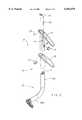
- FIG. 1is a side elevational view of a chair having the improved height-adjustable chair arm assembly of this invention mounted thereon, this view showing the right-side charm arm assembly;
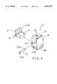
- FIG. 2is an exploded perspective view of a right-side height-adjustable chair arm assembly according to the present invention, the chair arm assembly being shown removed from the chair for clarity of description, and further a portion of the armrest being shown removed from the chair arm assembly for clarity of description;
- FIG. 3is a fragmentary sectional view of the chair arm assembly of FIG. 1, with the latch being shown engaged within one of the notches of the sleeve of the chair arm assembly so as to maintain the armrest at a desired height;
- FIG. 4is a sectional view taken generally along line 4--4 in FIG. 3;
- FIG. 5is an exploded perspective view of the compact cartridge assembly of FIG. 3;
- FIG. 6is a fragmentary sectional view of an upper portion of the chair arm assembly of FIG. 1 which shows the cooperation between the actuator rod and the actuator lever.
- FIG. 1diagrammatically illustrates a chair 2, often referred to as an office-type chair.
- This chairemploys a center pedestal 3 which projects upwardly from a base 4.
- a suitable seat assemblyis mounted on an upper end of the center pedestal 3.
- the seat assemblyincludes a chair seat 6 and a chair control or seat frame 5.
- the chair control 5supports the chair seat 6 and is mounted thereto.
- a chair back 7projects upwardly from a location above the rear edge of the chair seat 6.
- the chair 2is provided with a pair of height-adjustable arm assemblies 8 mounted thereon, namely right and left assemblies which are respectively disposed adjacent the right and left sides of the seat 6 so as to project upwardly therefrom to hence permit the chair occupant to be seated therebetween.
- the right and left chair arm assemblies 8are substantially identical except for being mirror images of one another, and only the right side assembly is visible in FIG. 1.
- the right side height-adjustable arm assembly 8includes an arm upright 10 which is fixed to and projects upwardly from adjacent the seat 6.
- the arm upright 10 in the illustrated embodimentis generally L-shaped and includes a base leg 10B which is fixed to the seat frame 5, and also includes a vertically elongate and upwardly cantilevered support leg or segment 10A.
- the support segment 10Ahas a plastic sleeve 11 fixed vertically therein.
- the sleeve 11defines a guide bore 13 which extends through the sleeve.
- the sleeve 11includes a plurality of uniformly vertically spaced notches 12 defined therein as shown in FIG. 3.
- the arm assembly 8further includes an arm element having a slide tube 16 fixed thereto and projecting downwardly therefrom.
- the tube 16which in the illustrated embodiment is rectangular in cross section, is slidably but nonrotatably supported within the guide bore 13 of the sleeve 11.
- the arm assembly 8additionally includes a compact cartridge assembly 17 which is secured interiorly of the tube 16 adjacent the lower end thereof.
- This cartridge assemblyhas a box-like housing 18, the front wall 18B of which fits within a window 16A formed in the side of the tube 16.
- the top and bottom walls of housing 18have tabs 31 which snap into position behind the tube wall to fixedly position the cartridge assembly 17 within the tube 16 while enabling the cartridge assembly to be inserted through the window 16A.
- the cartridge housing 18has a latch 19 slidably supported therein adjacent the bottom wall thereof and urged by a spring 20 so that the nose of the latch 19 projects through an opening 18A formed in the front wall of the housing 18 for engagement with one of the notches 12 formed in sleeve 11.
- the latch 19includes a pair of guide posts 25 (FIG. 5) which project outwardly from opposite sides thereof.
- the guide posts 25are slidably received within a pair of elongate guide slots 25A respectively defined with the opposed side walls of housing 18. Note that only one guide post 25 and one guide slot 25A are shown in FIG. 5.
- the latch 19has an upwardly tapered cam 21 defining thereon a generally flat cam surface 21A engaged by an elongated roller 22.
- the cam surface 21Ais downwardly sloped relative to the vertical so as to project toward the opening 18A.
- the reduced diameter end parts 22A of roller 22are confined within a pair of cam slots 23 formed in the opposed side walls of housing 18, which slots 23 are reversely inclined relative to the cam surface 21A. Note that only one cam slot 23 is shown in FIG. 5.
- Roller 22is resiliently retained within a bifurcated lower end of a vertically elongate actuator rod 24 which extends downwardly through an opening 20 defined in a horizontal top wall of the cartridge housing 18.
- the actuator rod 24projects upwardly through the tube 16 into the arm element 15 and has its upper end coupled to an actuator lever 26.
- the actuator lever 26is pivotally supported on the arm element 15 by a transverse horizontal pivot 29.
- the actuator lever 26has a finger-engaging part or pad 27 disposed under a front part of an armrest 28 of the arm assembly 8 for engagement by the chair occupant.
- actuator lever 26When the occupant presses pad 27 upwardly, actuator lever 26 is caused to pivot about pivot pin 29 against the bias of spring 30. In turn, actuator rod 24 is depressed by actuator lever 26 so as to cause the actuator rod to be forced downwardly to push the roller 22 against the inclined cam 21 to thereby withdraw the latch 19 from the notch 12. With the latch 19 withdrawn from the notch 12, the occupant can then vertically raise and lower the armrest 28. When reaching a desired position, the occupant releases the pad 27 and then any slight vertical movement will cause the spring 20 to urge the latch 19 into the closest adjacent notch 12 to lock the armrest 28 at a desired height.
Landscapes
- Health & Medical Sciences (AREA)
- Dentistry (AREA)
- General Health & Medical Sciences (AREA)
- Chair Legs, Seat Parts, And Backrests (AREA)
Abstract
Description
Claims (18)
Priority Applications (1)
| Application Number | Priority Date | Filing Date | Title |
|---|---|---|---|
| US08/774,353US6053579A (en) | 1996-12-27 | 1996-12-27 | Height-Adjustable chair arm assembly having cam-type adjusting mechanism |
Applications Claiming Priority (1)
| Application Number | Priority Date | Filing Date | Title |
|---|---|---|---|
| US08/774,353US6053579A (en) | 1996-12-27 | 1996-12-27 | Height-Adjustable chair arm assembly having cam-type adjusting mechanism |
Publications (1)
| Publication Number | Publication Date |
|---|---|
| US6053579Atrue US6053579A (en) | 2000-04-25 |
Family
ID=25100993
Family Applications (1)
| Application Number | Title | Priority Date | Filing Date |
|---|---|---|---|
| US08/774,353Expired - LifetimeUS6053579A (en) | 1996-12-27 | 1996-12-27 | Height-Adjustable chair arm assembly having cam-type adjusting mechanism |
Country Status (1)
| Country | Link |
|---|---|
| US (1) | US6053579A (en) |
Cited By (44)
| Publication number | Priority date | Publication date | Assignee | Title |
|---|---|---|---|---|
| US6139107A (en)* | 2000-03-17 | 2000-10-31 | Lee; Ching-Yang | Armrest adjusting mechanism |
| US6398309B1 (en)* | 2001-07-05 | 2002-06-04 | Su-Jan Chen | Level-adjustable and swivelable armrest assembly |
| US6523898B1 (en) | 1999-06-17 | 2003-02-25 | Steelcase Development Corporation | Chair construction |
| EP1258209A3 (en)* | 2001-05-16 | 2003-09-17 | Froli Kunststoffwerk Heinrich Fromme OHG | Adjustment mechanism for an arm-rest of a chair |
| US20030178882A1 (en)* | 2002-02-13 | 2003-09-25 | Schmitz Johann Burkhard | Back support structure |
| US20040070244A1 (en)* | 2002-02-11 | 2004-04-15 | Graco Children's Products Inc. | Child seat |
| US6733080B2 (en) | 1992-06-15 | 2004-05-11 | Herman Miller, Inc. | Seating structure having a backrest with a flexible membrane and a moveable armrest |
| US20040104611A1 (en)* | 1998-01-21 | 2004-06-03 | Caruso Jerome C. | Adjustable armrest |
| US6802566B2 (en) | 2000-09-28 | 2004-10-12 | Formway Furniture Limited | Arm assembly for a chair |
| US6824218B1 (en) | 2004-01-30 | 2004-11-30 | Knoll, Inc. | Height adjustment mechanism for a chair |
| US6840582B2 (en) | 2002-05-14 | 2005-01-11 | Formway Furniture Limited | Height adjustable arm assembly |
| US6974190B1 (en)* | 2005-03-17 | 2005-12-13 | Yu-Ching Hung | Armrest adjustment mechanism |
| US7011371B1 (en)* | 2004-11-29 | 2006-03-14 | Po-Chuan Tsai | Armrest assembly having a height adjustable function |
| US20070024100A1 (en)* | 2005-07-05 | 2007-02-01 | Chun Hui Chan | Adjustable armrest assembly |
| US20070057560A1 (en)* | 2005-03-01 | 2007-03-15 | Tim Fookes | Arm assembly for a chair |
| US20070278838A1 (en)* | 2006-06-02 | 2007-12-06 | Davis Judy G | Armrest |
| USD572490S1 (en) | 2006-06-05 | 2008-07-08 | Steelcase Inc. | Chair |
| USD572914S1 (en) | 2006-06-05 | 2008-07-15 | Steelcase Inc. | Chair |
| US20080296955A1 (en)* | 2007-06-01 | 2008-12-04 | Geister Jennifer K | Height adjustable armrest |
| US20090108660A1 (en)* | 2007-08-23 | 2009-04-30 | Weber Jeffrey A | Adjustable armrest and method for the use thereof |
| US20100038950A1 (en)* | 2008-02-11 | 2010-02-18 | Ching-Yang Lee | Height adjustment mechanism for armrest |
| US20100066147A1 (en)* | 2008-09-15 | 2010-03-18 | Po-Chuan Tsai | Chair Armrest having a Height Adjustable Function |
| USD637423S1 (en) | 2010-04-13 | 2011-05-10 | Herman Miller, Inc. | Chair |
| USD639091S1 (en) | 2010-04-13 | 2011-06-07 | Herman Miller, Inc. | Backrest |
| US20110140497A1 (en)* | 2008-05-02 | 2011-06-16 | Tim Fookes | Armrest for a chair |
| USD650206S1 (en) | 2010-04-13 | 2011-12-13 | Herman Miller, Inc. | Chair |
| USD652657S1 (en) | 2010-04-13 | 2012-01-24 | Herman Miller, Inc. | Chair |
| USD653061S1 (en) | 2010-04-13 | 2012-01-31 | Herman Miller, Inc. | Chair |
| US20120068512A1 (en)* | 2005-03-01 | 2012-03-22 | Haworth, Inc. | Arm assembly for a chair |
| USD657166S1 (en) | 2010-04-13 | 2012-04-10 | Herman Miller, Inc. | Chair |
| US8449037B2 (en) | 2010-04-13 | 2013-05-28 | Herman Miller, Inc. | Seating structure with a contoured flexible backrest |
| US20140117736A1 (en)* | 2011-02-10 | 2014-05-01 | L & P Property Management Company | Adjustable armrest for a seating unit |
| US8777318B2 (en) | 2012-06-01 | 2014-07-15 | Atec International Team Co., Ltd. | Height adjustment mechanism for armrest |
| US10220843B2 (en) | 2016-02-23 | 2019-03-05 | Deka Products Limited Partnership | Mobility device control system |
| USD846452S1 (en) | 2017-05-20 | 2019-04-23 | Deka Products Limited Partnership | Display housing |
| JP2020162985A (en)* | 2019-03-29 | 2020-10-08 | 株式会社オカムラ | Arm rest and chair |
| US10802495B2 (en) | 2016-04-14 | 2020-10-13 | Deka Products Limited Partnership | User control device for a transporter |
| US10908045B2 (en) | 2016-02-23 | 2021-02-02 | Deka Products Limited Partnership | Mobility device |
| US10926756B2 (en) | 2016-02-23 | 2021-02-23 | Deka Products Limited Partnership | Mobility device |
| USD915248S1 (en) | 2017-05-20 | 2021-04-06 | Deka Products Limited Partnership | Set of toggles |
| US11399995B2 (en) | 2016-02-23 | 2022-08-02 | Deka Products Limited Partnership | Mobility device |
| US11681293B2 (en) | 2018-06-07 | 2023-06-20 | Deka Products Limited Partnership | System and method for distributed utility service execution |
| USD1047785S1 (en) | 2017-05-20 | 2024-10-22 | Deka Products Limited Partnership | Toggle control device |
| US12440401B2 (en) | 2024-05-22 | 2025-10-14 | Deka Products Limited Partnership | Mobility device |
Citations (23)
| Publication number | Priority date | Publication date | Assignee | Title |
|---|---|---|---|---|
| US232790A (en)* | 1880-09-28 | Stool or chair | ||
| US441964A (en)* | 1890-12-02 | Francis neppert | ||
| US493111A (en)* | 1893-03-07 | Piano-stool | ||
| US504683A (en)* | 1893-09-05 | Joseph r | ||
| US2569834A (en)* | 1949-10-28 | 1951-10-02 | James W Smith | Armrest |
| US4489981A (en)* | 1983-01-31 | 1984-12-25 | Everest & Jennings, Inc. | Wheelchair adjustable arm rest assembly |
| US4934750A (en)* | 1988-03-10 | 1990-06-19 | Daimler-Benz Ag | Center console for motor vehicles |
| US5050933A (en)* | 1990-07-02 | 1991-09-24 | Marta Tornero | Stacking chair with collapsible arms |
| US5242138A (en)* | 1992-01-16 | 1993-09-07 | Gary Kornberg | Arm rest for a wheelchair |
| US5265938A (en)* | 1991-12-05 | 1993-11-30 | Westinghouse Electric Corp. | Adjustable arm for a chair |
| US5318347A (en)* | 1992-10-19 | 1994-06-07 | Shin Yeh Enterprise Co., Ltd. | Height-adjustable armrest unit for chair |
| US5324096A (en)* | 1992-03-02 | 1994-06-28 | Hon Industries Inc. | Adjustable height chair arm |
| US5346284A (en)* | 1992-09-10 | 1994-09-13 | Dauphin Entwicklungs- U. Beteiligungs-Gmbh | Seating furniture armrest |
| US5368365A (en)* | 1992-04-23 | 1994-11-29 | Global Upholstery Company | Adjustable arm rest assembly |
| US5382079A (en)* | 1993-10-25 | 1995-01-17 | Chromcraft Revington, Inc. | Adjustable arm attachable to a chair body |
| US5388892A (en)* | 1993-04-02 | 1995-02-14 | Tornero; Lino E. | Mechanism for the relative positioning of telescoping members |
| US5393124A (en)* | 1992-12-08 | 1995-02-28 | Neil; Gary K. | Armrest assembly |
| US5393125A (en)* | 1993-05-28 | 1995-02-28 | Steelcase Inc. | Height adjustable chair arm assembly |
| US5435626A (en)* | 1994-06-21 | 1995-07-25 | Lai; Yu-Shan | Armrest-adjusting mechanism |
| US5439267A (en)* | 1993-05-28 | 1995-08-08 | Steelcase Inc. | Chair with adjustable arm assemblies |
| US5620233A (en)* | 1995-06-07 | 1997-04-15 | Jami, Inc. | Adjusting mechanism for selectively positioning chair components |
| US5647638A (en)* | 1995-06-07 | 1997-07-15 | Haworth, Inc. | Height-adjustable chair arm assembly |
| US5829839A (en)* | 1996-10-17 | 1998-11-03 | Haworth, Inc. | Height-adjustable chair arm assembly having gear-type adjusting mechanism |
- 1996
- 1996-12-27USUS08/774,353patent/US6053579A/ennot_activeExpired - Lifetime
Patent Citations (24)
| Publication number | Priority date | Publication date | Assignee | Title |
|---|---|---|---|---|
| US232790A (en)* | 1880-09-28 | Stool or chair | ||
| US441964A (en)* | 1890-12-02 | Francis neppert | ||
| US493111A (en)* | 1893-03-07 | Piano-stool | ||
| US504683A (en)* | 1893-09-05 | Joseph r | ||
| US2569834A (en)* | 1949-10-28 | 1951-10-02 | James W Smith | Armrest |
| US4489981A (en)* | 1983-01-31 | 1984-12-25 | Everest & Jennings, Inc. | Wheelchair adjustable arm rest assembly |
| US4934750A (en)* | 1988-03-10 | 1990-06-19 | Daimler-Benz Ag | Center console for motor vehicles |
| US5050933A (en)* | 1990-07-02 | 1991-09-24 | Marta Tornero | Stacking chair with collapsible arms |
| US5265938A (en)* | 1991-12-05 | 1993-11-30 | Westinghouse Electric Corp. | Adjustable arm for a chair |
| US5242138A (en)* | 1992-01-16 | 1993-09-07 | Gary Kornberg | Arm rest for a wheelchair |
| US5324096A (en)* | 1992-03-02 | 1994-06-28 | Hon Industries Inc. | Adjustable height chair arm |
| US5368365A (en)* | 1992-04-23 | 1994-11-29 | Global Upholstery Company | Adjustable arm rest assembly |
| US5346284A (en)* | 1992-09-10 | 1994-09-13 | Dauphin Entwicklungs- U. Beteiligungs-Gmbh | Seating furniture armrest |
| US5318347A (en)* | 1992-10-19 | 1994-06-07 | Shin Yeh Enterprise Co., Ltd. | Height-adjustable armrest unit for chair |
| US5393124A (en)* | 1992-12-08 | 1995-02-28 | Neil; Gary K. | Armrest assembly |
| US5388892A (en)* | 1993-04-02 | 1995-02-14 | Tornero; Lino E. | Mechanism for the relative positioning of telescoping members |
| US5393125A (en)* | 1993-05-28 | 1995-02-28 | Steelcase Inc. | Height adjustable chair arm assembly |
| US5439267A (en)* | 1993-05-28 | 1995-08-08 | Steelcase Inc. | Chair with adjustable arm assemblies |
| US5382079A (en)* | 1993-10-25 | 1995-01-17 | Chromcraft Revington, Inc. | Adjustable arm attachable to a chair body |
| US5435626A (en)* | 1994-06-21 | 1995-07-25 | Lai; Yu-Shan | Armrest-adjusting mechanism |
| US5620233A (en)* | 1995-06-07 | 1997-04-15 | Jami, Inc. | Adjusting mechanism for selectively positioning chair components |
| US5647638A (en)* | 1995-06-07 | 1997-07-15 | Haworth, Inc. | Height-adjustable chair arm assembly |
| US5853223A (en)* | 1995-06-07 | 1998-12-29 | Haworth, Inc. | Height-adjustable chair arm assembly |
| US5829839A (en)* | 1996-10-17 | 1998-11-03 | Haworth, Inc. | Height-adjustable chair arm assembly having gear-type adjusting mechanism |
Non-Patent Citations (3)
| Title |
|---|
| Copending U.S. Ser. No. 08/731 712, filed Oct. 17, 1996 (Client Ref: Haworth Case 196) and copies of the drawings therefrom.* |
| Copending U.S. Ser. No. 08/857 032, filed May 15, 1997 (Client Ref: Haworth Case 165A) and copies of the drawings therefrom.* |
| U.S. Ser. No. 08,/486,613, filed Jul. 15, 1997, now attached U.S. Pat. No. 5,647,638 (Client Ref: Haworth Case 165).* |
Cited By (74)
| Publication number | Priority date | Publication date | Assignee | Title |
|---|---|---|---|---|
| US6733080B2 (en) | 1992-06-15 | 2004-05-11 | Herman Miller, Inc. | Seating structure having a backrest with a flexible membrane and a moveable armrest |
| US6877813B2 (en)* | 1998-01-21 | 2005-04-12 | Herman Miller, Inc. | Adjustable armrest |
| US20040104611A1 (en)* | 1998-01-21 | 2004-06-03 | Caruso Jerome C. | Adjustable armrest |
| US7740315B2 (en) | 1999-06-17 | 2010-06-22 | Steelcase Inc. | Back construction for seating unit |
| US20050093354A1 (en)* | 1999-06-17 | 2005-05-05 | Ball Douglas C. | Back construction for seating unit |
| US20040046432A1 (en)* | 1999-06-17 | 2004-03-11 | Ball Douglas C. | Chair construction |
| US20070057549A1 (en)* | 1999-06-17 | 2007-03-15 | Ball Douglas C | Back construction for seating unit |
| US6913315B2 (en) | 1999-06-17 | 2005-07-05 | Steelcase Development Corporation | Chair construction |
| US6523898B1 (en) | 1999-06-17 | 2003-02-25 | Steelcase Development Corporation | Chair construction |
| US6139107A (en)* | 2000-03-17 | 2000-10-31 | Lee; Ching-Yang | Armrest adjusting mechanism |
| US6802566B2 (en) | 2000-09-28 | 2004-10-12 | Formway Furniture Limited | Arm assembly for a chair |
| EP1258209A3 (en)* | 2001-05-16 | 2003-09-17 | Froli Kunststoffwerk Heinrich Fromme OHG | Adjustment mechanism for an arm-rest of a chair |
| US6398309B1 (en)* | 2001-07-05 | 2002-06-04 | Su-Jan Chen | Level-adjustable and swivelable armrest assembly |
| US20040070244A1 (en)* | 2002-02-11 | 2004-04-15 | Graco Children's Products Inc. | Child seat |
| US7419222B2 (en) | 2002-02-13 | 2008-09-02 | Herman Miller, Inc. | Support member for a seating structure |
| US20030178882A1 (en)* | 2002-02-13 | 2003-09-25 | Schmitz Johann Burkhard | Back support structure |
| US20060091715A1 (en)* | 2002-02-13 | 2006-05-04 | Herman Miller, Inc. | Support member for a seating structure |
| US7841666B2 (en) | 2002-02-13 | 2010-11-30 | Herman Miller, Inc. | Back support structure |
| US20090127905A1 (en)* | 2002-02-13 | 2009-05-21 | Herman Miller, Inc. | Back support structure |
| US7249802B2 (en) | 2002-02-13 | 2007-07-31 | Herman Miller, Inc. | Back support structure |
| US6840582B2 (en) | 2002-05-14 | 2005-01-11 | Formway Furniture Limited | Height adjustable arm assembly |
| US6824218B1 (en) | 2004-01-30 | 2004-11-30 | Knoll, Inc. | Height adjustment mechanism for a chair |
| US7011371B1 (en)* | 2004-11-29 | 2006-03-14 | Po-Chuan Tsai | Armrest assembly having a height adjustable function |
| US8235468B2 (en)* | 2005-03-01 | 2012-08-07 | Haworth, Inc. | Arm assembly for a chair |
| US20120068512A1 (en)* | 2005-03-01 | 2012-03-22 | Haworth, Inc. | Arm assembly for a chair |
| US7533939B2 (en) | 2005-03-01 | 2009-05-19 | Haworth, Inc. | Arm assembly for a chair |
| US20070057560A1 (en)* | 2005-03-01 | 2007-03-15 | Tim Fookes | Arm assembly for a chair |
| US20090189428A1 (en)* | 2005-03-01 | 2009-07-30 | Haworth, Inc. | Arm assembly for a chair |
| US7815259B2 (en) | 2005-03-01 | 2010-10-19 | Haworth, Inc. | Arm assembly for a chair |
| US6974190B1 (en)* | 2005-03-17 | 2005-12-13 | Yu-Ching Hung | Armrest adjustment mechanism |
| US20070024100A1 (en)* | 2005-07-05 | 2007-02-01 | Chun Hui Chan | Adjustable armrest assembly |
| US20070278838A1 (en)* | 2006-06-02 | 2007-12-06 | Davis Judy G | Armrest |
| US7644991B2 (en) | 2006-06-02 | 2010-01-12 | Steelcase Inc. | Chair with folding armrest |
| USD572490S1 (en) | 2006-06-05 | 2008-07-08 | Steelcase Inc. | Chair |
| USD572914S1 (en) | 2006-06-05 | 2008-07-15 | Steelcase Inc. | Chair |
| US7841665B2 (en) | 2007-06-01 | 2010-11-30 | Steelcase Inc. | Height adjustable armrest |
| US20080296955A1 (en)* | 2007-06-01 | 2008-12-04 | Geister Jennifer K | Height adjustable armrest |
| US20090108660A1 (en)* | 2007-08-23 | 2009-04-30 | Weber Jeffrey A | Adjustable armrest and method for the use thereof |
| US20100038950A1 (en)* | 2008-02-11 | 2010-02-18 | Ching-Yang Lee | Height adjustment mechanism for armrest |
| US7744159B2 (en)* | 2008-02-11 | 2010-06-29 | Isotech Products Incorporated | Height adjustment mechanism for armrest |
| US8132860B2 (en) | 2008-05-02 | 2012-03-13 | Haworth, Inc. | Armrest for a chair |
| US20110140497A1 (en)* | 2008-05-02 | 2011-06-16 | Tim Fookes | Armrest for a chair |
| US20100066147A1 (en)* | 2008-09-15 | 2010-03-18 | Po-Chuan Tsai | Chair Armrest having a Height Adjustable Function |
| US7896440B2 (en)* | 2008-09-15 | 2011-03-01 | Po-Chuan Tsai | Chair armrest having a height adjustable function |
| US9301615B2 (en) | 2010-04-13 | 2016-04-05 | Herman Miller, Inc. | Seating structure with a contoured flexible backrest |
| USD653061S1 (en) | 2010-04-13 | 2012-01-31 | Herman Miller, Inc. | Chair |
| USD652657S1 (en) | 2010-04-13 | 2012-01-24 | Herman Miller, Inc. | Chair |
| USD650206S1 (en) | 2010-04-13 | 2011-12-13 | Herman Miller, Inc. | Chair |
| USD657166S1 (en) | 2010-04-13 | 2012-04-10 | Herman Miller, Inc. | Chair |
| USD639091S1 (en) | 2010-04-13 | 2011-06-07 | Herman Miller, Inc. | Backrest |
| US8449037B2 (en) | 2010-04-13 | 2013-05-28 | Herman Miller, Inc. | Seating structure with a contoured flexible backrest |
| USD637423S1 (en) | 2010-04-13 | 2011-05-10 | Herman Miller, Inc. | Chair |
| US20140117736A1 (en)* | 2011-02-10 | 2014-05-01 | L & P Property Management Company | Adjustable armrest for a seating unit |
| US9173498B2 (en)* | 2011-02-10 | 2015-11-03 | L&P Property Management Company | Adjustable armrest for a seating unit |
| US8777318B2 (en) | 2012-06-01 | 2014-07-15 | Atec International Team Co., Ltd. | Height adjustment mechanism for armrest |
| US10220843B2 (en) | 2016-02-23 | 2019-03-05 | Deka Products Limited Partnership | Mobility device control system |
| US12023285B2 (en) | 2016-02-23 | 2024-07-02 | Deka Products Limited Partnership | Mobility device |
| US10752243B2 (en) | 2016-02-23 | 2020-08-25 | Deka Products Limited Partnership | Mobility device control system |
| US12240440B2 (en) | 2016-02-23 | 2025-03-04 | Deka Products Limited Partnership | Mobility device |
| US10908045B2 (en) | 2016-02-23 | 2021-02-02 | Deka Products Limited Partnership | Mobility device |
| US10926756B2 (en) | 2016-02-23 | 2021-02-23 | Deka Products Limited Partnership | Mobility device |
| US11794722B2 (en) | 2016-02-23 | 2023-10-24 | Deka Products Limited Partnership | Mobility device |
| US11399995B2 (en) | 2016-02-23 | 2022-08-02 | Deka Products Limited Partnership | Mobility device |
| US11679044B2 (en) | 2016-02-23 | 2023-06-20 | Deka Products Limited Partnership | Mobility device |
| US12117842B2 (en) | 2016-04-14 | 2024-10-15 | Deka Products Limited Partnership | User control device for a transporter |
| US10802495B2 (en) | 2016-04-14 | 2020-10-13 | Deka Products Limited Partnership | User control device for a transporter |
| US11720115B2 (en) | 2016-04-14 | 2023-08-08 | Deka Products Limited Partnership | User control device for a transporter |
| USD876994S1 (en) | 2017-05-20 | 2020-03-03 | Deka Products Limited Partnership | Display housing |
| USD915248S1 (en) | 2017-05-20 | 2021-04-06 | Deka Products Limited Partnership | Set of toggles |
| USD1047785S1 (en) | 2017-05-20 | 2024-10-22 | Deka Products Limited Partnership | Toggle control device |
| USD846452S1 (en) | 2017-05-20 | 2019-04-23 | Deka Products Limited Partnership | Display housing |
| US11681293B2 (en) | 2018-06-07 | 2023-06-20 | Deka Products Limited Partnership | System and method for distributed utility service execution |
| JP2020162985A (en)* | 2019-03-29 | 2020-10-08 | 株式会社オカムラ | Arm rest and chair |
| US12440401B2 (en) | 2024-05-22 | 2025-10-14 | Deka Products Limited Partnership | Mobility device |
Similar Documents
| Publication | Publication Date | Title |
|---|---|---|
| US6053579A (en) | Height-Adjustable chair arm assembly having cam-type adjusting mechanism | |
| US5829839A (en) | Height-adjustable chair arm assembly having gear-type adjusting mechanism | |
| US4451084A (en) | Backrest height adjustment for office chair | |
| US5037158A (en) | Height adjustment mechanism for chair back | |
| US6092871A (en) | Lumbar support | |
| US5265938A (en) | Adjustable arm for a chair | |
| US5439268A (en) | Adjustable armrest assembly for a chair | |
| US5895095A (en) | Adjustable armrest assemblies for chairs | |
| KR19990022262A (en) | Adjustable armrest assembly | |
| US5445432A (en) | Height adjusting means for a chair | |
| US5765920A (en) | Height-adjusting mechanism for arm rest of a chair | |
| KR102314380B1 (en) | Lumbar support for chair | |
| GB2224304A (en) | Mechanism for adjusting height of handle bar of pushcart | |
| US6811224B2 (en) | Chair with adjustable arms and/or back | |
| US5853222A (en) | Height-adjustable chair back | |
| US6422652B1 (en) | Height adjusting mechanism | |
| US5791734A (en) | Chair with a backrest which is continuously adjustable height | |
| US6705678B1 (en) | Height-adjustable chair back | |
| JPH10313974A (en) | Armrest device for chair | |
| JPH079161U (en) | Height adjustment mechanism for infant chair | |
| JPH07108015A (en) | Device for adjusting vertical position of armrest of chair | |
| JPH1033303A (en) | Chair sliding lock mechanism | |
| KR100605035B1 (en) | Chair integrated desk | |
| KR960000751Y1 (en) | Height and angle adjustable arm rest of chair | |
| KR950002792Y1 (en) | Chair available position adjustment for backrest |
Legal Events
| Date | Code | Title | Description |
|---|---|---|---|
| AS | Assignment | Owner name:HAWORTH, INC., MICHIGAN Free format text:ASSIGNMENT OF ASSIGNORS INTEREST;ASSIGNORS:NELSON, PATRICK C.;WILKERSON, LARRY A.;REEL/FRAME:008375/0595 Effective date:19970109 | |
| STCF | Information on status: patent grant | Free format text:PATENTED CASE | |
| CC | Certificate of correction | ||
| FPAY | Fee payment | Year of fee payment:4 | |
| FPAY | Fee payment | Year of fee payment:8 | |
| FPAY | Fee payment | Year of fee payment:12 | |
| AS | Assignment | Owner name:PNC BANK, NATIONAL ASSOCIATION, AS ADMINISTRATIVE Free format text:COLLATERAL ASSIGNMENT OF PATENTS;ASSIGNOR:HAWORTH, INC., HAWORTH, LTD. AND SUCCESSORS;REEL/FRAME:032606/0875 Effective date:20140403 | |
| AS | Assignment | Owner name:HAWORTH, INC., MICHIGAN Free format text:RELEASE BY SECURED PARTY;ASSIGNOR:PNC BANK, NATIONAL ASSOCIATION;REEL/FRAME:052788/0497 Effective date:20200528 Owner name:HAWORTH, LTD., MICHIGAN Free format text:RELEASE BY SECURED PARTY;ASSIGNOR:PNC BANK, NATIONAL ASSOCIATION;REEL/FRAME:052788/0497 Effective date:20200528 | |
| AS | Assignment | Owner name:PNC BANK, PENNSYLVANIA Free format text:COLLATERAL ASSIGNMENT OF PATENTS;ASSIGNORS:HAWORTH, INC.;AFFORDABLE INTERIOR SYSTEMS, INC.;REEL/FRAME:062078/0770 Effective date:20221129 |