US6052606A - Reversible keypad and display for a telephone handset - Google Patents
Reversible keypad and display for a telephone handsetDownload PDFInfo
- Publication number
- US6052606A US6052606AUS08/989,463US98946397AUS6052606AUS 6052606 AUS6052606 AUS 6052606AUS 98946397 AUS98946397 AUS 98946397AUS 6052606 AUS6052606 AUS 6052606A
- Authority
- US
- United States
- Prior art keywords
- screen
- display
- keys
- mode
- telephone
- Prior art date
- Legal status (The legal status is an assumption and is not a legal conclusion. Google has not performed a legal analysis and makes no representation as to the accuracy of the status listed.)
- Expired - Lifetime
Links
Images


Classifications
- H—ELECTRICITY
- H04—ELECTRIC COMMUNICATION TECHNIQUE
- H04M—TELEPHONIC COMMUNICATION
- H04M1/00—Substation equipment, e.g. for use by subscribers
- H04M1/02—Constructional features of telephone sets
- H04M1/0202—Portable telephone sets, e.g. cordless phones, mobile phones or bar type handsets
- H—ELECTRICITY
- H04—ELECTRIC COMMUNICATION TECHNIQUE
- H04M—TELEPHONIC COMMUNICATION
- H04M1/00—Substation equipment, e.g. for use by subscribers
- H04M1/72—Mobile telephones; Cordless telephones, i.e. devices for establishing wireless links to base stations without route selection
- H04M1/724—User interfaces specially adapted for cordless or mobile telephones
- H04M1/72403—User interfaces specially adapted for cordless or mobile telephones with means for local support of applications that increase the functionality
- H04M1/7243—User interfaces specially adapted for cordless or mobile telephones with means for local support of applications that increase the functionality with interactive means for internal management of messages
- H—ELECTRICITY
- H04—ELECTRIC COMMUNICATION TECHNIQUE
- H04M—TELEPHONIC COMMUNICATION
- H04M2250/00—Details of telephonic subscriber devices
- H04M2250/16—Details of telephonic subscriber devices including more than one display unit
- H—ELECTRICITY
- H04—ELECTRIC COMMUNICATION TECHNIQUE
- H04M—TELEPHONIC COMMUNICATION
- H04M2250/00—Details of telephonic subscriber devices
- H04M2250/22—Details of telephonic subscriber devices including a touch pad, a touch sensor or a touch detector
Definitions
- This inventionrelates to cellular telephone handsets and, more particularly, to a cellular telephone handset provided with an improved display and key pad system.
- a typical cellular telephone handsethas a small display screen for viewing information and a keypad for entering data, such as a telephone number to be called, and to control and select functions to be performed by the handset.
- Many telephone handsetsare designed to receive paging messages, store information in memory, recall information from the memory, and display it on the display screen of the handset, as well as provide for voice telephone communications.
- Modern telephone handsetshave become very small and, as a result, the display screen on such handsets are, accordingly, quite small. As a result, the amount of information that can be displayed in a given instant of time is limited.
- the small display screensare quite adequate for normal telephone operations, but when the display screen operates to display a received message such as sent with a page or an E-mail message, the size of the screen becomes a handicap because it is inadequate to display enough information at one time. Similarly, the size of the screen becomes a disadvantage when the handset is operated to display maps, pictures or X-ray photographs.
- the present inventionprovides an improved solution to the problem in that it provides two screens, one which would normally function in telephone dialing operations as a display screen and the second screen will implement the keypad in a touch sensitive mode for the telephone dialing operations.
- the small display screenwill be used in telephone dialing operations to display information related to telephone dialing, such as displaying the number to be called.
- the roles of the two screensare reversed.
- the small screenthen becomes a touch sensitive keypad implementing a small number of keys to control the function of the device and the larger screen, which formerly implemented a telephone keypad, then serves the function of displaying information. In this manner, the entire larger screen used to implement the telephone keypad becomes available to display information and enables a larger amount of information to be displayed simultaneously on the screen.
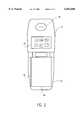
- FIG. 1illustrates a view in elevation of the functional side of the telephone handset of the invention when operating in a normal telephone dialing mode
- FIG. 2illustrates the same view of the telephone handset, but showing the display when the handset is operating in the alternate mode to display a large amount of data and with the smaller display screen being used to define a limited functional keypad;
- FIG. 3illustrates a schematic sectional view through one of the display screens illustrating the arrangement of the functional components of the display screen
- FIG. 4is a block diagram of the electrical circuit of the handset of the invention.
- FIG. 5is a block diagram of a circuit employed to a selectively energize electroluminescent panels employed to backlight the display screens.
- the cellular phone handset of the present inventioncomprises two casing sections 11 and 13 which are hinged together to permit the handset to be folded up to make it convenient for carrying in a pocket or handbag.
- the upper casing section 11contains a speaker 15 and a touch sensitive display screen 17.
- the lower casing section 13contains a touch sensitive display screen 19 and a microphone 21.
- the display screens 17 and 19are of the liquid crystal display type.
- the lower display screen 19When operating in the telephone dialing mode as shown in FIG. 1, the lower display screen 19 will be controlled to display a keypad comprising a set of 18 keys, each of which will be located over a touch sensitive target on the display screen 19.
- the lower 12 keyswill correspond to the keypad of a conventional telephone and include the conventional alpha-numeric insignia of the conventional telephone keypad.
- the upper 6 keyswill correspond to control functions. When operating in the telephone dialing mode wherein the keypad is displayed as shown in FIG. 1, the user will press one of the function keys to obtain a dial tone and then may dial a selected number by touching the keys of the telephone number to be called.
- one of the function keyscan be used in combination with the digit keys of the telephone keypad to automatically dial numbers stored in the memory of the system. In either case, the dialed number will be displayed on the display screen 17 and in the case of an automatic dialing, the name of the person being dialed may also be displayed.
- the function keysin addition to initiating a call and enabling automatic dialing would also be used to terminate a call and perform other selected functions such as calling up information from memory to be displayed on the display screen 17, such as a list of the persons or places that can be automatically dialed and the associated keypad digit or digits for effecting the automatic dialing.
- the mode of operation represented by FIG. 1would also be used when it was desired to enter data into the memory of the handset, or to transmit data to a remote location to which a telephone connection has been made, using the telephone keypad displayed on the screen.
- the data entered or transmittedwould be displayed on the screen 17.
- One of the upper six function keyswill be a mode switching key and will bear an appropriate insignia to indicate this function, such as an "M" or the word "MODE".
- MODE switching keyWhen the MODE switching key is touched by the user, the mode of operation is switched to that represented by FIG. 2 in which the lower display screen 19 becomes an information displaying screen and the upper screen 17 is used to display a set of function keys, which in the preferred embodiment consist of 6 function keys.
- the keys corresponding to the telephone keypadare not needed in this mode of operation since the handset will not be used in this mode for dialing a number to be called. The user can switch the mode shown in FIG.
- the touch sensitive function keys displayed on the upper screen 17may include functions to control the display, such as keys to scroll up or down, or keys to page up and down.
- One of the function keys displayed on the screenmay also be provided to effect a hang up or disconnect.
- One of the function keyswill be a mode switching key and bear an appropriate insignia, such as an "M” or the word "MODE" to indicate that it has this function.
- the mode of operationUpon the operator touching the mode switching key, the mode of operation will be then switched back to that shown in FIG. 1 to enable the user of the system to initiate another call by dialing another telephone number by touching the appropriate keys which will then be displayed on the display screen 19, or to use the telephone keypad to enter or transmit data.
- Each of the display screenswill be provided with two electro-luminescent panels providing backlighting.
- the screencan be backlit two ways, one way being to backlight just the keys being displayed on the screen and the other way being to backlight the entire screen.
- this backlightingis carried out by one of the panels operating to backlight only the displayed keys and the other panel functioning to backlight the areas outside the keys.
- a display screenis operating as a keypad, only the electro-luminescent panel which illuminates only the keys would be energized.
- both electro-luminescent panelswill be energized.
- FIG. 3is a schematic exploded sectional view of the display screen 19 showing the arrangement of the components of the display screen.
- the display screencomprises a liquid crystal display unit 27a on top of which is a touch sensitive overlay 29a.
- the liquid crystal display unit 27awill be controlled to display the outline of the keys of the keypad as well as the insignia on each of the keys.
- An electro-luminescent panel 30ais positioned beneath the liquid crystal display 27a and will operate when energized to backlight the area of the screen outside the keys displayed by the liquid crystal display unit 27a.
- a second electro-luminescent panel 31a positioned beneath the panel 30aoperates to backlight the areas within the key outlines displayed by the liquid crystal display unit 27a.
- the display screen 17comprises an identical arrangement of components as the display screen 19, which components are identified as the liquid crystal display unit 27b, a touch sensitive overlay 29b, and electroluminescent panels 30b and 31b, which provide backlighting to the screen 17 in the same manner as the electroluminescent panels 30a and 31a provide backlighting to the screen 19.
- the display screensare controlled to backlight only the displayed keys when such display screen is operating in a keypad mode and to backlight the entire screen when such display screen is operating in an information display mode.
- the liquid crystal display units 27a and 27bwill display each key by displaying a closed figure defining the outline of the key and insignia within the key to identify the key and/or its function.
- the liquid crystal closed figure outlinecan be omitted so that only the backlighting provided by the electroluminscent panel 31a or 31b and the liquid crystal display of key insignia define the target area of each key.
- a microprocessor 28 of the handsetwill control the liquid crystal display unit 27a for the screen 19 to display the telephone keypad on the screen 19 as shown in FIG. 1 and will respond to the touching of the target areas in the touch sensitive overlay 29a corresponding to the displayed keys on the screen 19 to carry out the functions or the dialing directed by the touching of the corresponding displayed keys on the screen 19 by the liquid crystal display unit 27a.
- the microprocessor 28controls a cellular telephone circuit 40 to carry out dialing and other cellular telephone functions and receives data transmitted to the telephone circuit 40.
- the microprocessor 28When the handset is operating in the information display mode, the microprocessor 28 will control the liquid crystal display unit 29b for the screen 17 to display the function keys on the display screen 17 as shown in FIG. 2 and the microprocessor 28 will respond to the touching of the function keys displayed on the screen 17 to carry out the functions called for by the touching of the function keys.
- the circuit for controlling the energization of the electro-luminescent panelscomprises an electroluminescent lamp driver 41 which, when the power for the handset is turned on, will apply power to both the electroluminescent panels 31a and 31b continuously to always backlight the areas inside the keys so that this backlighting is provided whether or not the keys are displayed.
- the power from the electroluminescent lamp driver 41is also applied to a high voltage switch 43 which is controlled by the microprocessor 28.
- the high voltage switch 43will apply the power from the electroluminescent lamp driver 41 to the electro-luminescent panel 30b for the screen 17, but not to the electroluminescent panel 30a for the screen 19.
- both EL panels 30b and 31b for the screen 17will be energized to backlight the whole screen 17 and in the screen 19, only the electroluminescent panel 31a will be energized so that in the screen 19, only the areas within the displayed keys in the keypad are backlit.
- both panels 31a and 31bwill still be energized, but in this mode of operation, the electroluminscent panel 30a for the screen 19 will be energized and the electroluminescent panel 30b for the screen 17 will be turned off.
- the area inside the displayed keys on the screen 17will be backlit and the whole screen 19 will be backlit in this mode of operation.
- the useris provided with a relatively large screen area to display information without unduly restricting the area for the keypad use for dialing a number for outgoing calls.
- the preferred embodiment of the inventionis a cellular telephone handset of the folding type in which there is a need to limit the size of the screen area for displaying information.
- the inventive conceptmay also be employed in conventional directly connected telephones as well as in cordless telephone handsets.
Landscapes
- Engineering & Computer Science (AREA)
- Signal Processing (AREA)
- Human Computer Interaction (AREA)
- Computer Networks & Wireless Communication (AREA)
- Telephone Set Structure (AREA)
- Telephone Function (AREA)
Abstract
Description
Claims (8)
Priority Applications (1)
| Application Number | Priority Date | Filing Date | Title |
|---|---|---|---|
| US08/989,463US6052606A (en) | 1997-12-12 | 1997-12-12 | Reversible keypad and display for a telephone handset |
Applications Claiming Priority (1)
| Application Number | Priority Date | Filing Date | Title |
|---|---|---|---|
| US08/989,463US6052606A (en) | 1997-12-12 | 1997-12-12 | Reversible keypad and display for a telephone handset |
Publications (1)
| Publication Number | Publication Date |
|---|---|
| US6052606Atrue US6052606A (en) | 2000-04-18 |
Family
ID=25535134
Family Applications (1)
| Application Number | Title | Priority Date | Filing Date |
|---|---|---|---|
| US08/989,463Expired - LifetimeUS6052606A (en) | 1997-12-12 | 1997-12-12 | Reversible keypad and display for a telephone handset |
Country Status (1)
| Country | Link |
|---|---|
| US (1) | US6052606A (en) |
Cited By (21)
| Publication number | Priority date | Publication date | Assignee | Title |
|---|---|---|---|---|
| USD459730S1 (en) | 2001-03-15 | 2002-07-02 | Novatel Wireless, Inc. | Dialer application display screen for a portable computing device |
| US6424823B1 (en)* | 2000-02-09 | 2002-07-23 | Samsung Electronics Co., Ltd. | Cell phone with integrated personal mirror |
| US6505056B1 (en)* | 1999-06-04 | 2003-01-07 | Inst Information Ind | Data displaying device and a method for requesting a data updating |
| KR20030018523A (en)* | 2001-08-30 | 2003-03-06 | 엘지전자 주식회사 | Keypad sensing device in mobile phone |
| WO2003009091A3 (en)* | 2001-07-16 | 2003-05-22 | Ii Carroll Alexis Spencer | Functional identifiers on wireless devices |
| US6640114B2 (en) | 2000-05-11 | 2003-10-28 | Youngbo Engineering, Inc. | Method and apparatus for data entry in a wireless network access device |
| US20040002355A1 (en)* | 2002-06-29 | 2004-01-01 | Spencer Carroll Alexis | Functional identifiers on wireless devices for gaming/wagering/lottery applications and methods of using same |
| US20040067762A1 (en)* | 2002-10-03 | 2004-04-08 | Henrik Balle | Method and device for entering text |
| US20040198307A1 (en)* | 2002-09-11 | 2004-10-07 | Suli Chang | Mobile phone with two input modes |
| US6871048B2 (en)* | 1998-04-28 | 2005-03-22 | Sony Corporation | Mobil communication apparatus and information providing system using the mobile communication apparatus |
| US20050143137A1 (en)* | 2003-12-25 | 2005-06-30 | Fujitsu Limited | Terminal apparatus |
| US6983168B2 (en)* | 2000-05-26 | 2006-01-03 | Benq Corporation | Back light holder for a mobile phone |
| US7012595B2 (en)* | 2001-03-30 | 2006-03-14 | Koninklijke Philips Electronics N.V. | Handheld electronic device with touch pad |
| US20070273662A1 (en)* | 2006-05-26 | 2007-11-29 | Hon Hai Precision Industry Co., Ltd. | Display apparatus and display method for a portable device |
| US7804489B1 (en)* | 2001-08-29 | 2010-09-28 | Palmsource Inc. | Method and apparatus for displaying information in a display screen region identified by permanent printing |
| US20110092256A1 (en)* | 2001-10-16 | 2011-04-21 | Research In Motion Limited | Handheld mobile communication device |
| CN102769693A (en)* | 2011-05-06 | 2012-11-07 | 宏碁股份有限公司 | Low power consumption mobile communication device and working method |
| USRE43931E1 (en)* | 1997-12-30 | 2013-01-15 | Ericsson Inc. | Radiotelephones having contact-sensitive user interfaces and methods of operating same |
| US9153088B2 (en) | 2004-10-22 | 2015-10-06 | Smart Cellco, Inc. | RFID functionality for portable electronic devices |
| US9519898B2 (en) | 2004-10-22 | 2016-12-13 | Smart Cellco, Inc. | Wearable electronic devices and mobile transactions and/or actions |
| USD1090622S1 (en)* | 2024-04-05 | 2025-08-26 | Soo Hoon Cho | Display screen or portion thereof with animated graphical user interface |
Citations (12)
| Publication number | Priority date | Publication date | Assignee | Title |
|---|---|---|---|---|
| US4268721A (en)* | 1977-05-02 | 1981-05-19 | Sri International | Portable telephone communication device for the hearing impaired |
| US5335276A (en)* | 1992-12-16 | 1994-08-02 | Texas Instruments Incorporated | Communication system and methods for enhanced information transfer |
| US5422656A (en)* | 1993-11-01 | 1995-06-06 | International Business Machines Corp. | Personal communicator having improved contrast control for a liquid crystal, touch sensitive display |
| US5465401A (en)* | 1992-12-15 | 1995-11-07 | Texas Instruments Incorporated | Communication system and methods for enhanced information transfer |
| US5537608A (en)* | 1992-11-13 | 1996-07-16 | International Business Machines Corporation | Personal communicator apparatus |
| US5568536A (en)* | 1994-07-25 | 1996-10-22 | International Business Machines Corporation | Selective reconfiguration method and apparatus in a multiple application personal communications device |
| US5572573A (en)* | 1994-01-25 | 1996-11-05 | U S West Advanced Technologies, Inc. | Removable user interface for use with interactive electronic devices |
| US5581243A (en)* | 1990-06-04 | 1996-12-03 | Microslate Inc. | Method and apparatus for displaying simulated keyboards on touch-sensitive displays |
| US5584054A (en)* | 1994-07-18 | 1996-12-10 | Motorola, Inc. | Communication device having a movable front cover for exposing a touch sensitive display |
| US5615384A (en)* | 1993-11-01 | 1997-03-25 | International Business Machines Corporation | Personal communicator having improved zoom and pan functions for editing information on touch sensitive display |
| US5633912A (en)* | 1993-07-08 | 1997-05-27 | U S West Advanced Technologies, Inc. | Mobile telephone user interface including fixed and dynamic function keys and method of using same |
| US5808862A (en)* | 1992-12-22 | 1998-09-15 | Ncr Corporation | Computer configuration which allows conversion between multiple operative positions |
- 1997
- 1997-12-12USUS08/989,463patent/US6052606A/ennot_activeExpired - Lifetime
Patent Citations (12)
| Publication number | Priority date | Publication date | Assignee | Title |
|---|---|---|---|---|
| US4268721A (en)* | 1977-05-02 | 1981-05-19 | Sri International | Portable telephone communication device for the hearing impaired |
| US5581243A (en)* | 1990-06-04 | 1996-12-03 | Microslate Inc. | Method and apparatus for displaying simulated keyboards on touch-sensitive displays |
| US5537608A (en)* | 1992-11-13 | 1996-07-16 | International Business Machines Corporation | Personal communicator apparatus |
| US5465401A (en)* | 1992-12-15 | 1995-11-07 | Texas Instruments Incorporated | Communication system and methods for enhanced information transfer |
| US5335276A (en)* | 1992-12-16 | 1994-08-02 | Texas Instruments Incorporated | Communication system and methods for enhanced information transfer |
| US5808862A (en)* | 1992-12-22 | 1998-09-15 | Ncr Corporation | Computer configuration which allows conversion between multiple operative positions |
| US5633912A (en)* | 1993-07-08 | 1997-05-27 | U S West Advanced Technologies, Inc. | Mobile telephone user interface including fixed and dynamic function keys and method of using same |
| US5422656A (en)* | 1993-11-01 | 1995-06-06 | International Business Machines Corp. | Personal communicator having improved contrast control for a liquid crystal, touch sensitive display |
| US5615384A (en)* | 1993-11-01 | 1997-03-25 | International Business Machines Corporation | Personal communicator having improved zoom and pan functions for editing information on touch sensitive display |
| US5572573A (en)* | 1994-01-25 | 1996-11-05 | U S West Advanced Technologies, Inc. | Removable user interface for use with interactive electronic devices |
| US5584054A (en)* | 1994-07-18 | 1996-12-10 | Motorola, Inc. | Communication device having a movable front cover for exposing a touch sensitive display |
| US5568536A (en)* | 1994-07-25 | 1996-10-22 | International Business Machines Corporation | Selective reconfiguration method and apparatus in a multiple application personal communications device |
Cited By (30)
| Publication number | Priority date | Publication date | Assignee | Title |
|---|---|---|---|---|
| US8812059B2 (en) | 1997-12-30 | 2014-08-19 | Ericsson, Inc. | Radiotelephones having contact-sensitive user interfaces and methods of operating same |
| USRE43931E1 (en)* | 1997-12-30 | 2013-01-15 | Ericsson Inc. | Radiotelephones having contact-sensitive user interfaces and methods of operating same |
| US6871048B2 (en)* | 1998-04-28 | 2005-03-22 | Sony Corporation | Mobil communication apparatus and information providing system using the mobile communication apparatus |
| US6505056B1 (en)* | 1999-06-04 | 2003-01-07 | Inst Information Ind | Data displaying device and a method for requesting a data updating |
| US6424823B1 (en)* | 2000-02-09 | 2002-07-23 | Samsung Electronics Co., Ltd. | Cell phone with integrated personal mirror |
| US6640114B2 (en) | 2000-05-11 | 2003-10-28 | Youngbo Engineering, Inc. | Method and apparatus for data entry in a wireless network access device |
| US6983168B2 (en)* | 2000-05-26 | 2006-01-03 | Benq Corporation | Back light holder for a mobile phone |
| USD459730S1 (en) | 2001-03-15 | 2002-07-02 | Novatel Wireless, Inc. | Dialer application display screen for a portable computing device |
| US7012595B2 (en)* | 2001-03-30 | 2006-03-14 | Koninklijke Philips Electronics N.V. | Handheld electronic device with touch pad |
| WO2003009091A3 (en)* | 2001-07-16 | 2003-05-22 | Ii Carroll Alexis Spencer | Functional identifiers on wireless devices |
| US9679436B2 (en) | 2001-07-16 | 2017-06-13 | Cell Lotto, Inc. | Functional identifiers on wireless devices for gaming/wagering/lottery applications and methods of using same |
| US10360756B2 (en) | 2001-07-16 | 2019-07-23 | Cell Lotto, Inc. | Functional identifiers on wireless devices for gaming/wagering/lottery applications and methods of using same |
| US7804489B1 (en)* | 2001-08-29 | 2010-09-28 | Palmsource Inc. | Method and apparatus for displaying information in a display screen region identified by permanent printing |
| KR20030018523A (en)* | 2001-08-30 | 2003-03-06 | 엘지전자 주식회사 | Keypad sensing device in mobile phone |
| US20110092256A1 (en)* | 2001-10-16 | 2011-04-21 | Research In Motion Limited | Handheld mobile communication device |
| US9286754B2 (en) | 2002-06-29 | 2016-03-15 | Cell Lotto, Inc. | Functional identifiers on wireless devices for gaming/wagering/lottery applications and methods of using same |
| US8452242B2 (en)* | 2002-06-29 | 2013-05-28 | Cell Lotto, Inc. | Functional identifiers on wireless devices for gaming/wagering/lottery applications and methods of using same |
| US20040002355A1 (en)* | 2002-06-29 | 2004-01-01 | Spencer Carroll Alexis | Functional identifiers on wireless devices for gaming/wagering/lottery applications and methods of using same |
| US7031758B2 (en)* | 2002-09-11 | 2006-04-18 | Fih Co., Ltd. | Mobile phone with two input modes |
| US20040198307A1 (en)* | 2002-09-11 | 2004-10-07 | Suli Chang | Mobile phone with two input modes |
| US20040067762A1 (en)* | 2002-10-03 | 2004-04-08 | Henrik Balle | Method and device for entering text |
| US20050143137A1 (en)* | 2003-12-25 | 2005-06-30 | Fujitsu Limited | Terminal apparatus |
| US9153088B2 (en) | 2004-10-22 | 2015-10-06 | Smart Cellco, Inc. | RFID functionality for portable electronic devices |
| US9519898B2 (en) | 2004-10-22 | 2016-12-13 | Smart Cellco, Inc. | Wearable electronic devices and mobile transactions and/or actions |
| US9779404B2 (en) | 2004-10-22 | 2017-10-03 | Smart Cellco, Inc. | Business transactions over portable electronic devices with social media filters |
| US10387870B2 (en) | 2004-10-22 | 2019-08-20 | Smart Cellco, Inc. | RFID/NFC functionality for portable electronic devices |
| US10990958B2 (en) | 2004-10-22 | 2021-04-27 | Smart Cellco, Inc. | RFID/NFC functionality for portable electronic devices |
| US20070273662A1 (en)* | 2006-05-26 | 2007-11-29 | Hon Hai Precision Industry Co., Ltd. | Display apparatus and display method for a portable device |
| CN102769693A (en)* | 2011-05-06 | 2012-11-07 | 宏碁股份有限公司 | Low power consumption mobile communication device and working method |
| USD1090622S1 (en)* | 2024-04-05 | 2025-08-26 | Soo Hoon Cho | Display screen or portion thereof with animated graphical user interface |
Similar Documents
| Publication | Publication Date | Title |
|---|---|---|
| US6052606A (en) | Reversible keypad and display for a telephone handset | |
| US7203521B2 (en) | Method of displaying speed dials on a screen of a mobile communication terminal | |
| US6195569B1 (en) | Phone displaying alternative functionality menu | |
| JP2826469B2 (en) | Mobile phone | |
| US5737394A (en) | Portable telephone apparatus having a plurality of selectable functions activated by the use of dedicated and/or soft keys | |
| US20080167081A1 (en) | Keyless touch-screen cellular telephone | |
| EP0802659A1 (en) | Portable telephone with pivotally mounted keypad | |
| EP1942641B1 (en) | Apparatus and method for originating call by using image | |
| JP2003134204A (en) | Mobile phone | |
| GB2344261A (en) | Means for stopping a call alert and placing an incoming call on hold | |
| KR20020070752A (en) | Pocket telephone | |
| KR100334796B1 (en) | Keypad device in a mobile telecommunication terminal having touch-screen | |
| JP3379476B2 (en) | Mobile terminal with display | |
| JP3501710B2 (en) | Mobile phone | |
| JP4132902B2 (en) | Mobile terminal device, display control method and program for mobile terminal device | |
| US8036712B1 (en) | Radio apparatus with a control element for selecting and/or activating functions displayed on a display device | |
| JP3411158B2 (en) | Telephone | |
| JPS61163764A (en) | Telephone with search-type automatic dialing function | |
| JP4014003B2 (en) | Mobile phone | |
| JP4161561B2 (en) | Mobile terminal, pointer control method thereof, and program thereof | |
| KR100191820B1 (en) | Secondary speed dial device | |
| KR100360872B1 (en) | Mobile information terminal | |
| JPH10145469A (en) | Portable telephone set | |
| KR100845828B1 (en) | 3-stage dual LCD clamshell portable terminal and its control method | |
| JPH08139799A (en) | Telephone device |
Legal Events
| Date | Code | Title | Description |
|---|---|---|---|
| AS | Assignment | Owner name:LOCKHEED MARTIN CORPORATION, MARYLAND Free format text:ASSIGNMENT OF ASSIGNORS INTEREST;ASSIGNOR:BOWEN, RONALD A.;REEL/FRAME:008902/0418 Effective date:19971208 | |
| STCF | Information on status: patent grant | Free format text:PATENTED CASE | |
| AS | Assignment | Owner name:BAE SYSTEMS INFORMATION AND ELECTRONIC SYSTEMS INT Free format text:ASSIGNMENT OF ASSIGNORS INTEREST;ASSIGNOR:LOCKHEED MARTIN CORPORATION;REEL/FRAME:012287/0780 Effective date:20001127 | |
| FEPP | Fee payment procedure | Free format text:PAYOR NUMBER ASSIGNED (ORIGINAL EVENT CODE: ASPN); ENTITY STATUS OF PATENT OWNER: LARGE ENTITY | |
| FPAY | Fee payment | Year of fee payment:4 | |
| FPAY | Fee payment | Year of fee payment:8 | |
| AS | Assignment | Owner name:SCENERA TECHNOLOGIES, LLC, NEW HAMPSHIRE Free format text:ASSIGNMENT OF ASSIGNORS INTEREST;ASSIGNOR:BAE SYSTEMS INFORMATION AND ELECTRONIC SYSTEMS INTEGRATION INC.;REEL/FRAME:023870/0156 Effective date:20100122 Owner name:RETRO REFLECTIVE OPTICS,NEW HAMPSHIRE Free format text:ASSIGNMENT OF ASSIGNORS INTEREST;ASSIGNOR:BAE SYSTEMS INFORMATION AND ELECTRONIC SYSTEMS INTEGRATION INC.;REEL/FRAME:023870/0156 Effective date:20100122 Owner name:RETRO REFLECTIVE OPTICS, NEW HAMPSHIRE Free format text:ASSIGNMENT OF ASSIGNORS INTEREST;ASSIGNOR:BAE SYSTEMS INFORMATION AND ELECTRONIC SYSTEMS INTEGRATION INC.;REEL/FRAME:023870/0156 Effective date:20100122 | |
| AS | Assignment | Owner name:RETRO REFLECTIVE OPTICS,NEW HAMPSHIRE Free format text:ASSIGNMENT OF ASSIGNORS INTEREST;ASSIGNOR:BAE SYSTEMS INFORMATION AND ELECTRONIC SYSTEMS INTEGRATION INC.;REEL/FRAME:023915/0043 Effective date:20100122 Owner name:RETRO REFLECTIVE OPTICS, NEW HAMPSHIRE Free format text:ASSIGNMENT OF ASSIGNORS INTEREST;ASSIGNOR:BAE SYSTEMS INFORMATION AND ELECTRONIC SYSTEMS INTEGRATION INC.;REEL/FRAME:023915/0043 Effective date:20100122 | |
| AS | Assignment | Owner name:CREDIT SUISSE MANAGEMENT LLC,NEW YORK Free format text:SECURITY AGREEMENT;ASSIGNOR:RETRO REFLECTIVE OPTICS, LLC;REEL/FRAME:023905/0580 Effective date:20100122 Owner name:CREDIT SUISSE MANAGEMENT LLC, NEW YORK Free format text:SECURITY AGREEMENT;ASSIGNOR:RETRO REFLECTIVE OPTICS, LLC;REEL/FRAME:023905/0580 Effective date:20100122 | |
| FEPP | Fee payment procedure | Free format text:PAYER NUMBER DE-ASSIGNED (ORIGINAL EVENT CODE: RMPN); ENTITY STATUS OF PATENT OWNER: LARGE ENTITY Free format text:PAYOR NUMBER ASSIGNED (ORIGINAL EVENT CODE: ASPN); ENTITY STATUS OF PATENT OWNER: LARGE ENTITY | |
| FPAY | Fee payment | Year of fee payment:12 |