US6052212A - Method and apparatus for correcting coma in a high resolution scanner - Google Patents
Method and apparatus for correcting coma in a high resolution scannerDownload PDFInfo
- Publication number
- US6052212A US6052212AUS09/211,237US21123798AUS6052212AUS 6052212 AUS6052212 AUS 6052212AUS 21123798 AUS21123798 AUS 21123798AUS 6052212 AUS6052212 AUS 6052212A
- Authority
- US
- United States
- Prior art keywords
- sub
- cylinder
- cylinder mirror
- reflective face
- coma
- Prior art date
- Legal status (The legal status is an assumption and is not a legal conclusion. Google has not performed a legal analysis and makes no representation as to the accuracy of the status listed.)
- Expired - Lifetime
Links
Images

Classifications
- G—PHYSICS
- G02—OPTICS
- G02B—OPTICAL ELEMENTS, SYSTEMS OR APPARATUS
- G02B27/00—Optical systems or apparatus not provided for by any of the groups G02B1/00 - G02B26/00, G02B30/00
- G02B27/0025—Optical systems or apparatus not provided for by any of the groups G02B1/00 - G02B26/00, G02B30/00 for optical correction, e.g. distorsion, aberration
- G02B27/0031—Optical systems or apparatus not provided for by any of the groups G02B1/00 - G02B26/00, G02B30/00 for optical correction, e.g. distorsion, aberration for scanning purposes
Definitions
- This inventionrelates in general to the field of high resolution optical scanners and more specifically relates to a technique to eliminate coma in the image formed by such scanners.
- Optical scannersare widely used in laser equipment to digitize images on reflective or transmissive media, or to print images on reflective or transmissive media. In the former application, the laser beam is unmodulated, while in the latter application, the laser beam is modulated with information.
- One application of an optical scanneris to create depth or motion images on lenticular material having a recording layer. Spatially multiplexed images are exposed onto the recording layer by a laser optical scanner.
- the conjugating cylinderoperate a reducing magnification less than 1 ⁇ which will reduce the size of the image of the spot on the polygon.
- magnification of the conjugating cylinderdeparts from 1 ⁇ it introduces coma into the image. This is the dilemma for the optical designer.
- the desire to have a small spot at the image planerequires either a small spot on the polygon facet (thus producing diffraction artifacts) or a high reducing magnification in the conjugating cylinder (thus producing coma) which actually enlarges the spot.
- FIG. 1aillustrates how a point source 10 imaged by the curved surface of a cylinder mirror 20 on axis (i.e., an angle of incidence of 0 degrees) is imaged to a coma-free image point 30.
- FIG. 1billustrates how a point source 10 imaged by the curved surface of a cylinder mirror 20 tilted by an angle 40 with respect to the optical axis produces an image 30 aberrated by a certain amount of coma 50.
- the amount of comadepends upon the radius of curvature of the surface, the distance between the object and the mirror surface, the distance between the mirror surface and the image, the angle of tilt of the mirror with respect to the optical axis, and the numerical aperture of the light.
- the magnificationis 1 and there is no coma.
- a method of correcting a scanning device's reflective face's pyramid error as well as coma in the cross scan direction of an optical scanning systemcomprising the steps of: focusing a beam of light to a spot in the cross scan axis in the vicinity of the scanning device's reflective face with a first cylinder mirror which is tilted at an angle to produce a fixed, known amount of coma in the spot focused in the cross scan axis; and imaging the location of the reflective face, and thus reimaging the spot, to a second image position with a second cylinder mirror which is tilted at a second angle, the second cylinder mirror imaging the spot with a fixed and known amount of coma in the cross scan axis which is approximately equal to and opposite in sign to the first fixed, known amount of coma.
- the inventionhas the following advantages.
- This inventionprovides an optical solution which allows for the conjugating cylinder to work at a magnification other than 1 ⁇ while the final image remains free from coma.
- This inventionprovides a mathematical method of designing such a system.
- FIGS. 1a and 1bare diagrammatic views useful in understanding the source of errors in an optical scanning system.
- FIG. 2is a diagrammatic view useful in understanding the present invention.
- FIG. 3is a diagrammatic view of an embodiment of the present invention.
- FIG. 4is a cross-sectional view of lenticular recording media.
- FIG. 2illustrates the concept of the invention, that is, how a single point can be imaged by two cylinder mirrors with the final image having no coma.
- a point source 10is imaged at a magnification not equal to 1 by a curved mirror 20 tilted by an angle 40 producing an image 30 which is aberrated by a certain amount of coma 50.
- This aberrated image 30is directed towards a second mirror surface 60 tilted by an angle 70 and reimages the aberrated image 30 to a final image 80 which is coma free.
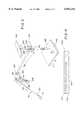
- FIG. 3illustrates the preferred embodiment of the invention.
- Laser light 100 in one or more wavelengthsexists from a source 110, such as modulated laser diode.
- a relay lens 120images the laser light 100 to a beam waist location 140.
- the lighttravels a distance 130 from the beam waist location 140 and is reflected by a cylinder mirror 160 towards a second cylinder mirror 200 at an angle 180.
- the second cylinder mirror 200has a power axis orthogonal to the first cylinder mirror 160 power axis.
- the first and second cylinder mirrors 160,200are separated by an axial distance 132.
- the second cylinder mirror 200creates a focused beam waist 240 in a plane parallel to the axis of the reflective face of a scanning device, such as the rotating polygon facet 220.
- Beam waist 240has a fixed amount of coma.
- the polygon facet 220redirects and scans the laser light towards a beam folding mirror 230 at an axial distance 136 from polygon facet 220.
- Beam folding mirror 230directs the scanning beam by an angle 250 towards a third cylinder mirror 260 located an axial distance 138 from beam folding mirror 230.
- the third cylinder mirror 260has a power axis in the cross-scan direction and redirects the laser beam by an angle 300.
- the beamis focused in the crossscan axis to the image plane 280 a distance 142 from cylinder mirror 260.
- Image plans 280is represented by recording media 400.
- the scanning devicecan also be a reciprocating galvo mirror.
- the third cylinder mirror 260conjugates the polygon facet plan 220 with the final image plane 280 in the cross-scan axis such that the coma induced by said second cylinder 200 is canceled at the image plane 280. This occurs when the following equation is satisfied:
- R 1Radius of Curvature of cylinder 20
- R 2Radius of Curvature of cylinder 26
- recording media 400is lenticular media (FIG. 4) including a recording layer 402 (such as photosensitive media) and a lenticular layer 404 including lenticular lenses 406.
- the modulated laser beamis scanned across media 400 in the direction of arrow B (FIG. 3), and parallel to the long cylindrical axes of the lenticular lenses in the media.
- Media 400is moved in the direction of arrow A to provide scanning in a direction orthogonal to the direction of arrow B.
Landscapes
- Physics & Mathematics (AREA)
- General Physics & Mathematics (AREA)
- Optics & Photonics (AREA)
- Mechanical Optical Scanning Systems (AREA)
- Facsimile Scanning Arrangements (AREA)
- Lenses (AREA)
Abstract
Description
l.sub.1 '.sup.2 [(l.sub.1 '/l.sub.1)-1]×tan(I.sub.1)/R.sub.1 cos(I.sub.1) =l.sub.2 '.sup.2 [(l.sub.2 '/l.sub.2)-1]×tan(I.sub.2)/R.sub.2 cos(I.sub.2)
Claims (22)
l.sub.1 '.sup.2 [(l.sub.1 '÷l.sub.1)-1]×tan(I.sub.1)÷R.sub.1 cos(I.sub.1) =l.sub.2 '.sup.2 [(l.sub.2 '÷l.sub.2)-1]×tan(I.sub.2)÷R.sub.2 cos(I.sub.2)
l.sub.1 '.sup.2 [(l.sub.1 '÷l.sub.1)-1]×tan(I.sub.1)÷R.sub.1 cos(I.sub.1) =l.sub.2 '.sup.2 [(l.sub.2 '÷l.sub.2)-1]×tan(I.sub.2)÷R.sub.2 cos(I.sub.2).
Priority Applications (3)
| Application Number | Priority Date | Filing Date | Title |
|---|---|---|---|
| US09/211,237US6052212A (en) | 1998-12-14 | 1998-12-14 | Method and apparatus for correcting coma in a high resolution scanner |
| EP99203848AEP1011004A3 (en) | 1998-12-14 | 1999-11-17 | Method and apparatus for correcting coma in a high resolution scanner |
| JP11352723AJP2000214404A (en) | 1998-12-14 | 1999-12-13 | Method and device for correcting coma in high-resolution scanner |
Applications Claiming Priority (1)
| Application Number | Priority Date | Filing Date | Title |
|---|---|---|---|
| US09/211,237US6052212A (en) | 1998-12-14 | 1998-12-14 | Method and apparatus for correcting coma in a high resolution scanner |
Publications (1)
| Publication Number | Publication Date |
|---|---|
| US6052212Atrue US6052212A (en) | 2000-04-18 |
Family
ID=22786090
Family Applications (1)
| Application Number | Title | Priority Date | Filing Date |
|---|---|---|---|
| US09/211,237Expired - LifetimeUS6052212A (en) | 1998-12-14 | 1998-12-14 | Method and apparatus for correcting coma in a high resolution scanner |
Country Status (3)
| Country | Link |
|---|---|
| US (1) | US6052212A (en) |
| EP (1) | EP1011004A3 (en) |
| JP (1) | JP2000214404A (en) |
Cited By (1)
| Publication number | Priority date | Publication date | Assignee | Title |
|---|---|---|---|---|
| US20040238765A1 (en)* | 2003-05-26 | 2004-12-02 | Andreas Bode | Device for detecting information contained in a phosphor layer |
Families Citing this family (1)
| Publication number | Priority date | Publication date | Assignee | Title |
|---|---|---|---|---|
| DE10251239B4 (en)* | 2002-11-04 | 2009-01-29 | Dilo Trading Ag | Anode for lithium polymer cells and method of manufacture |
Citations (10)
| Publication number | Priority date | Publication date | Assignee | Title |
|---|---|---|---|---|
| US3897132A (en)* | 1973-02-08 | 1975-07-29 | Agfa Gevaert Ag | Method and apparatus for correcting pyramidal error in an optical system with a mirror wheel |
| US4633272A (en)* | 1985-04-02 | 1986-12-30 | Eastman Kodak Company | Laser printing apparatus having a multiple formatted output |
| US4759593A (en)* | 1986-03-21 | 1988-07-26 | Eastman Kodak Company | High resolution optical scanner |
| US4832429A (en)* | 1983-01-19 | 1989-05-23 | T. R. Whitney Corporation | Scanning imaging system and method |
| US4848885A (en)* | 1988-05-09 | 1989-07-18 | Polaroid Corporation | Preobjective scanning system |
| US5168386A (en)* | 1990-10-22 | 1992-12-01 | Tencor Instruments | Flat field telecentric scanner |
| US5235438A (en)* | 1990-08-21 | 1993-08-10 | Dainippon Screen Mfg. Co. Ltd. | Image scanning and recording method and apparatus for compensating for a pyramidal error of a rotating polygon |
| US5267057A (en)* | 1990-08-21 | 1993-11-30 | Dainippon Screen Mfg., Co., Ltd. | Image scanning and recording method and apparatus for compensating for a pyramidal error of a rotating polygon |
| US5343326A (en)* | 1993-08-02 | 1994-08-30 | Xerox Corporation | Compact ros imaging system |
| US5768001A (en)* | 1996-06-10 | 1998-06-16 | Agfa Division, Bayer Corp. | Rotating beam deflector having an integral wave front correction element |
Family Cites Families (3)
| Publication number | Priority date | Publication date | Assignee | Title |
|---|---|---|---|---|
| GB2141554A (en)* | 1983-06-15 | 1984-12-19 | Philips Electronic Associated | A slit imaging system using two concave mirrors |
| US4921320A (en)* | 1988-09-22 | 1990-05-01 | Eastman Kodak Company | Optical scanner |
| US5491578A (en)* | 1994-12-19 | 1996-02-13 | Xerox Corporation | Optics for passive scan angle doubling |
- 1998
- 1998-12-14USUS09/211,237patent/US6052212A/ennot_activeExpired - Lifetime
- 1999
- 1999-11-17EPEP99203848Apatent/EP1011004A3/ennot_activeWithdrawn
- 1999-12-13JPJP11352723Apatent/JP2000214404A/enactivePending
Patent Citations (10)
| Publication number | Priority date | Publication date | Assignee | Title |
|---|---|---|---|---|
| US3897132A (en)* | 1973-02-08 | 1975-07-29 | Agfa Gevaert Ag | Method and apparatus for correcting pyramidal error in an optical system with a mirror wheel |
| US4832429A (en)* | 1983-01-19 | 1989-05-23 | T. R. Whitney Corporation | Scanning imaging system and method |
| US4633272A (en)* | 1985-04-02 | 1986-12-30 | Eastman Kodak Company | Laser printing apparatus having a multiple formatted output |
| US4759593A (en)* | 1986-03-21 | 1988-07-26 | Eastman Kodak Company | High resolution optical scanner |
| US4848885A (en)* | 1988-05-09 | 1989-07-18 | Polaroid Corporation | Preobjective scanning system |
| US5235438A (en)* | 1990-08-21 | 1993-08-10 | Dainippon Screen Mfg. Co. Ltd. | Image scanning and recording method and apparatus for compensating for a pyramidal error of a rotating polygon |
| US5267057A (en)* | 1990-08-21 | 1993-11-30 | Dainippon Screen Mfg., Co., Ltd. | Image scanning and recording method and apparatus for compensating for a pyramidal error of a rotating polygon |
| US5168386A (en)* | 1990-10-22 | 1992-12-01 | Tencor Instruments | Flat field telecentric scanner |
| US5343326A (en)* | 1993-08-02 | 1994-08-30 | Xerox Corporation | Compact ros imaging system |
| US5768001A (en)* | 1996-06-10 | 1998-06-16 | Agfa Division, Bayer Corp. | Rotating beam deflector having an integral wave front correction element |
Cited By (2)
| Publication number | Priority date | Publication date | Assignee | Title |
|---|---|---|---|---|
| US20040238765A1 (en)* | 2003-05-26 | 2004-12-02 | Andreas Bode | Device for detecting information contained in a phosphor layer |
| US7247874B2 (en)* | 2003-05-26 | 2007-07-24 | Agfa-Gevaert Healthcare Gmbh | Device for detecting information contained in a phosphor layer |
Also Published As
| Publication number | Publication date |
|---|---|
| EP1011004A3 (en) | 2003-05-14 |
| JP2000214404A (en) | 2000-08-04 |
| EP1011004A2 (en) | 2000-06-21 |
Similar Documents
| Publication | Publication Date | Title |
|---|---|---|
| US4759593A (en) | High resolution optical scanner | |
| US4099829A (en) | Flat field optical scanning system | |
| JP3433070B2 (en) | Light beam scanning device | |
| KR100228975B1 (en) | A device and a method for correcting astigmatism, bow distortion and field curvature | |
| JPH09274152A (en) | Multi-beam writing optical system | |
| KR100335624B1 (en) | Laser Beam Injection Device | |
| US6052212A (en) | Method and apparatus for correcting coma in a high resolution scanner | |
| KR20010014242A (en) | Anamorphic scan lens for laser scanner | |
| US7274498B2 (en) | Post-objective scanning device | |
| JPH08248345A (en) | Optical scanning device | |
| JPH0618802A (en) | Optical scanning device | |
| JP3198750B2 (en) | Optical scanning device | |
| US5381259A (en) | Raster output scanner (ROS) using an overfilled polygon design with minimized optical path length | |
| JP3192537B2 (en) | Scanning optical device | |
| JP2952197B2 (en) | Image scanning device | |
| JPH04170510A (en) | Post-objective scanning optical system and image forming device | |
| JPH07318838A (en) | Optical scanning device | |
| JP2974343B2 (en) | Optical scanning optical system and image scanning apparatus using the optical system | |
| JPS628016Y2 (en) | ||
| JPS6226733Y2 (en) | ||
| JPH03107811A (en) | scanning optical device | |
| JPS62127818A (en) | Optical light beam scanner | |
| JPH0772403A (en) | Optical scanning device | |
| JPH03223712A (en) | Laser light scanner | |
| JP2001021823A (en) | Optical adjustment method for optical scanner |
Legal Events
| Date | Code | Title | Description |
|---|---|---|---|
| AS | Assignment | Owner name:EASTMAN KODAK COMPANY, NEW YORK Free format text:ASSIGNMENT OF ASSIGNORS INTEREST;ASSIGNOR:COBB, JOSHUA M.;REEL/FRAME:009668/0859 Effective date:19981211 | |
| STCF | Information on status: patent grant | Free format text:PATENTED CASE | |
| FEPP | Fee payment procedure | Free format text:PAYOR NUMBER ASSIGNED (ORIGINAL EVENT CODE: ASPN); ENTITY STATUS OF PATENT OWNER: LARGE ENTITY | |
| FPAY | Fee payment | Year of fee payment:4 | |
| FPAY | Fee payment | Year of fee payment:8 | |
| FPAY | Fee payment | Year of fee payment:12 | |
| AS | Assignment | Owner name:CITICORP NORTH AMERICA, INC., AS AGENT, NEW YORK Free format text:SECURITY INTEREST;ASSIGNORS:EASTMAN KODAK COMPANY;PAKON, INC.;REEL/FRAME:028201/0420 Effective date:20120215 | |
| AS | Assignment | Owner name:WILMINGTON TRUST, NATIONAL ASSOCIATION, AS AGENT, MINNESOTA Free format text:PATENT SECURITY AGREEMENT;ASSIGNORS:EASTMAN KODAK COMPANY;PAKON, INC.;REEL/FRAME:030122/0235 Effective date:20130322 Owner name:WILMINGTON TRUST, NATIONAL ASSOCIATION, AS AGENT, Free format text:PATENT SECURITY AGREEMENT;ASSIGNORS:EASTMAN KODAK COMPANY;PAKON, INC.;REEL/FRAME:030122/0235 Effective date:20130322 | |
| AS | Assignment | Owner name:BANK OF AMERICA N.A., AS AGENT, MASSACHUSETTS Free format text:INTELLECTUAL PROPERTY SECURITY AGREEMENT (ABL);ASSIGNORS:EASTMAN KODAK COMPANY;FAR EAST DEVELOPMENT LTD.;FPC INC.;AND OTHERS;REEL/FRAME:031162/0117 Effective date:20130903 Owner name:BARCLAYS BANK PLC, AS ADMINISTRATIVE AGENT, NEW YORK Free format text:INTELLECTUAL PROPERTY SECURITY AGREEMENT (SECOND LIEN);ASSIGNORS:EASTMAN KODAK COMPANY;FAR EAST DEVELOPMENT LTD.;FPC INC.;AND OTHERS;REEL/FRAME:031159/0001 Effective date:20130903 Owner name:JPMORGAN CHASE BANK, N.A., AS ADMINISTRATIVE, DELAWARE Free format text:INTELLECTUAL PROPERTY SECURITY AGREEMENT (FIRST LIEN);ASSIGNORS:EASTMAN KODAK COMPANY;FAR EAST DEVELOPMENT LTD.;FPC INC.;AND OTHERS;REEL/FRAME:031158/0001 Effective date:20130903 Owner name:EASTMAN KODAK COMPANY, NEW YORK Free format text:RELEASE OF SECURITY INTEREST IN PATENTS;ASSIGNORS:CITICORP NORTH AMERICA, INC., AS SENIOR DIP AGENT;WILMINGTON TRUST, NATIONAL ASSOCIATION, AS JUNIOR DIP AGENT;REEL/FRAME:031157/0451 Effective date:20130903 Owner name:JPMORGAN CHASE BANK, N.A., AS ADMINISTRATIVE, DELA Free format text:INTELLECTUAL PROPERTY SECURITY AGREEMENT (FIRST LIEN);ASSIGNORS:EASTMAN KODAK COMPANY;FAR EAST DEVELOPMENT LTD.;FPC INC.;AND OTHERS;REEL/FRAME:031158/0001 Effective date:20130903 Owner name:PAKON, INC., NEW YORK Free format text:RELEASE OF SECURITY INTEREST IN PATENTS;ASSIGNORS:CITICORP NORTH AMERICA, INC., AS SENIOR DIP AGENT;WILMINGTON TRUST, NATIONAL ASSOCIATION, AS JUNIOR DIP AGENT;REEL/FRAME:031157/0451 Effective date:20130903 Owner name:BARCLAYS BANK PLC, AS ADMINISTRATIVE AGENT, NEW YO Free format text:INTELLECTUAL PROPERTY SECURITY AGREEMENT (SECOND LIEN);ASSIGNORS:EASTMAN KODAK COMPANY;FAR EAST DEVELOPMENT LTD.;FPC INC.;AND OTHERS;REEL/FRAME:031159/0001 Effective date:20130903 | |
| AS | Assignment | Owner name:PAKON, INC., NEW YORK Free format text:RELEASE BY SECURED PARTY;ASSIGNOR:JP MORGAN CHASE BANK, N.A., AS ADMINISTRATIVE AGENT;REEL/FRAME:049814/0001 Effective date:20190617 Owner name:KODAK AVIATION LEASING LLC, NEW YORK Free format text:RELEASE BY SECURED PARTY;ASSIGNOR:JP MORGAN CHASE BANK, N.A., AS ADMINISTRATIVE AGENT;REEL/FRAME:049814/0001 Effective date:20190617 Owner name:EASTMAN KODAK COMPANY, NEW YORK Free format text:RELEASE BY SECURED PARTY;ASSIGNOR:JP MORGAN CHASE BANK, N.A., AS ADMINISTRATIVE AGENT;REEL/FRAME:049814/0001 Effective date:20190617 Owner name:FAR EAST DEVELOPMENT LTD., NEW YORK Free format text:RELEASE BY SECURED PARTY;ASSIGNOR:JP MORGAN CHASE BANK, N.A., AS ADMINISTRATIVE AGENT;REEL/FRAME:049814/0001 Effective date:20190617 Owner name:KODAK IMAGING NETWORK, INC., NEW YORK Free format text:RELEASE BY SECURED PARTY;ASSIGNOR:JP MORGAN CHASE BANK, N.A., AS ADMINISTRATIVE AGENT;REEL/FRAME:049814/0001 Effective date:20190617 Owner name:KODAK REALTY, INC., NEW YORK Free format text:RELEASE BY SECURED PARTY;ASSIGNOR:JP MORGAN CHASE BANK, N.A., AS ADMINISTRATIVE AGENT;REEL/FRAME:049814/0001 Effective date:20190617 Owner name:KODAK AMERICAS, LTD., NEW YORK Free format text:RELEASE BY SECURED PARTY;ASSIGNOR:JP MORGAN CHASE BANK, N.A., AS ADMINISTRATIVE AGENT;REEL/FRAME:049814/0001 Effective date:20190617 Owner name:KODAK PORTUGUESA LIMITED, NEW YORK Free format text:RELEASE BY SECURED PARTY;ASSIGNOR:JP MORGAN CHASE BANK, N.A., AS ADMINISTRATIVE AGENT;REEL/FRAME:049814/0001 Effective date:20190617 Owner name:NPEC, INC., NEW YORK Free format text:RELEASE BY SECURED PARTY;ASSIGNOR:JP MORGAN CHASE BANK, N.A., AS ADMINISTRATIVE AGENT;REEL/FRAME:049814/0001 Effective date:20190617 Owner name:LASER PACIFIC MEDIA CORPORATION, NEW YORK Free format text:RELEASE BY SECURED PARTY;ASSIGNOR:JP MORGAN CHASE BANK, N.A., AS ADMINISTRATIVE AGENT;REEL/FRAME:049814/0001 Effective date:20190617 Owner name:QUALEX, INC., NEW YORK Free format text:RELEASE BY SECURED PARTY;ASSIGNOR:JP MORGAN CHASE BANK, N.A., AS ADMINISTRATIVE AGENT;REEL/FRAME:049814/0001 Effective date:20190617 Owner name:FPC, INC., NEW YORK Free format text:RELEASE BY SECURED PARTY;ASSIGNOR:JP MORGAN CHASE BANK, N.A., AS ADMINISTRATIVE AGENT;REEL/FRAME:049814/0001 Effective date:20190617 Owner name:KODAK PHILIPPINES, LTD., NEW YORK Free format text:RELEASE BY SECURED PARTY;ASSIGNOR:JP MORGAN CHASE BANK, N.A., AS ADMINISTRATIVE AGENT;REEL/FRAME:049814/0001 Effective date:20190617 Owner name:KODAK (NEAR EAST), INC., NEW YORK Free format text:RELEASE BY SECURED PARTY;ASSIGNOR:JP MORGAN CHASE BANK, N.A., AS ADMINISTRATIVE AGENT;REEL/FRAME:049814/0001 Effective date:20190617 Owner name:CREO MANUFACTURING AMERICA LLC, NEW YORK Free format text:RELEASE BY SECURED PARTY;ASSIGNOR:JP MORGAN CHASE BANK, N.A., AS ADMINISTRATIVE AGENT;REEL/FRAME:049814/0001 Effective date:20190617 | |
| AS | Assignment | Owner name:LASER PACIFIC MEDIA CORPORATION, NEW YORK Free format text:RELEASE BY SECURED PARTY;ASSIGNOR:BARCLAYS BANK PLC;REEL/FRAME:052773/0001 Effective date:20170202 Owner name:NPEC INC., NEW YORK Free format text:RELEASE BY SECURED PARTY;ASSIGNOR:BARCLAYS BANK PLC;REEL/FRAME:052773/0001 Effective date:20170202 Owner name:KODAK PHILIPPINES LTD., NEW YORK Free format text:RELEASE BY SECURED PARTY;ASSIGNOR:BARCLAYS BANK PLC;REEL/FRAME:052773/0001 Effective date:20170202 Owner name:FAR EAST DEVELOPMENT LTD., NEW YORK Free format text:RELEASE BY SECURED PARTY;ASSIGNOR:BARCLAYS BANK PLC;REEL/FRAME:052773/0001 Effective date:20170202 Owner name:EASTMAN KODAK COMPANY, NEW YORK Free format text:RELEASE BY SECURED PARTY;ASSIGNOR:BARCLAYS BANK PLC;REEL/FRAME:052773/0001 Effective date:20170202 Owner name:KODAK (NEAR EAST) INC., NEW YORK Free format text:RELEASE BY SECURED PARTY;ASSIGNOR:BARCLAYS BANK PLC;REEL/FRAME:052773/0001 Effective date:20170202 Owner name:QUALEX INC., NEW YORK Free format text:RELEASE BY SECURED PARTY;ASSIGNOR:BARCLAYS BANK PLC;REEL/FRAME:052773/0001 Effective date:20170202 Owner name:KODAK AMERICAS LTD., NEW YORK Free format text:RELEASE BY SECURED PARTY;ASSIGNOR:BARCLAYS BANK PLC;REEL/FRAME:052773/0001 Effective date:20170202 Owner name:KODAK REALTY INC., NEW YORK Free format text:RELEASE BY SECURED PARTY;ASSIGNOR:BARCLAYS BANK PLC;REEL/FRAME:052773/0001 Effective date:20170202 Owner name:FPC INC., NEW YORK Free format text:RELEASE BY SECURED PARTY;ASSIGNOR:BARCLAYS BANK PLC;REEL/FRAME:052773/0001 Effective date:20170202 |