US6051957A - Battery pack having a state of charge indicator - Google Patents
Battery pack having a state of charge indicatorDownload PDFInfo
- Publication number
- US6051957A US6051957AUS09/176,574US17657498AUS6051957AUS 6051957 AUS6051957 AUS 6051957AUS 17657498 AUS17657498 AUS 17657498AUS 6051957 AUS6051957 AUS 6051957A
- Authority
- US
- United States
- Prior art keywords
- battery
- charge
- amount
- discharge
- display
- Prior art date
- Legal status (The legal status is an assumption and is not a legal conclusion. Google has not performed a legal analysis and makes no representation as to the accuracy of the status listed.)
- Expired - Lifetime
Links
- 238000005259measurementMethods0.000claimsabstractdescription11
- 238000000034methodMethods0.000claimsdescription25
- 239000004973liquid crystal related substanceSubstances0.000claimsdescription3
- 230000001413cellular effectEffects0.000description5
- 238000004364calculation methodMethods0.000description4
- 238000012544monitoring processMethods0.000description3
- 238000013459approachMethods0.000description2
- 238000001514detection methodMethods0.000description2
- 238000007599dischargingMethods0.000description2
- 238000004590computer programMethods0.000description1
- 238000010586diagramMethods0.000description1
- 230000000694effectsEffects0.000description1
- 238000012986modificationMethods0.000description1
- 230000004048modificationEffects0.000description1
- 239000000126substanceSubstances0.000description1
Images


Classifications
- H—ELECTRICITY
- H01—ELECTRIC ELEMENTS
- H01M—PROCESSES OR MEANS, e.g. BATTERIES, FOR THE DIRECT CONVERSION OF CHEMICAL ENERGY INTO ELECTRICAL ENERGY
- H01M10/00—Secondary cells; Manufacture thereof
- H01M10/42—Methods or arrangements for servicing or maintenance of secondary cells or secondary half-cells
- H01M10/48—Accumulators combined with arrangements for measuring, testing or indicating the condition of cells, e.g. the level or density of the electrolyte
- H—ELECTRICITY
- H02—GENERATION; CONVERSION OR DISTRIBUTION OF ELECTRIC POWER
- H02J—CIRCUIT ARRANGEMENTS OR SYSTEMS FOR SUPPLYING OR DISTRIBUTING ELECTRIC POWER; SYSTEMS FOR STORING ELECTRIC ENERGY
- H02J7/00—Circuit arrangements for charging or depolarising batteries or for supplying loads from batteries
- H02J7/0047—Circuit arrangements for charging or depolarising batteries or for supplying loads from batteries with monitoring or indicating devices or circuits
- H02J7/0048—Detection of remaining charge capacity or state of charge [SOC]
- H—ELECTRICITY
- H01—ELECTRIC ELEMENTS
- H01M—PROCESSES OR MEANS, e.g. BATTERIES, FOR THE DIRECT CONVERSION OF CHEMICAL ENERGY INTO ELECTRICAL ENERGY
- H01M6/00—Primary cells; Manufacture thereof
- H01M6/50—Methods or arrangements for servicing or maintenance, e.g. for maintaining operating temperature
- H01M6/5044—Cells or batteries structurally combined with cell condition indicating means
- Y—GENERAL TAGGING OF NEW TECHNOLOGICAL DEVELOPMENTS; GENERAL TAGGING OF CROSS-SECTIONAL TECHNOLOGIES SPANNING OVER SEVERAL SECTIONS OF THE IPC; TECHNICAL SUBJECTS COVERED BY FORMER USPC CROSS-REFERENCE ART COLLECTIONS [XRACs] AND DIGESTS
- Y02—TECHNOLOGIES OR APPLICATIONS FOR MITIGATION OR ADAPTATION AGAINST CLIMATE CHANGE
- Y02E—REDUCTION OF GREENHOUSE GAS [GHG] EMISSIONS, RELATED TO ENERGY GENERATION, TRANSMISSION OR DISTRIBUTION
- Y02E60/00—Enabling technologies; Technologies with a potential or indirect contribution to GHG emissions mitigation
- Y02E60/10—Energy storage using batteries
Definitions
- This inventionrelates to batteries for portable devices such as computers, camcorders and cellular phones.
- Batteriesare used to power portable electronic equipment. Often batteries are used with equipment that give an indication of an amount of charge left in the battery.
- the charge indicatordisplays an indication of a percentage of useful power remaining compared to that the full charged battery.
- these indicatorsare carried by the battery cell and are often of the chemical type.
- the indicatorsare produced by circuits contained in the electronic device such as the cell phone or the like. When the indicator is produced by the device, the indicator is often a display such as an LCD display of a battery divided into segments. Each segment is lit or enabled to represent a percentage of power left in the battery. As power is drained from the battery segments are turned off with remaining lit ones indicating the remaining power in the battery.
- a battery pack for a portable electronic deviceincludes a case for carrying a battery.
- the casesupports a charge sensing circuit carried by the case, the charge sensing circuit producing a discharge signal corresponding to a measurement of an amount of charge removed from a battery.
- the casealso supports a processor responsive to the discharge signal from the charge sensor circuit to produce a signal corresponding to an amount of time prior to discharge of the battery based on a current rate of discharge and a display responsive to the signal to display a time period corresponding to the amount of time to discharge the battery based upon the current rate of discharge of the battery.
- the battery packcan include a charge sensor circuit that measures the amount of charge removed from the battery.
- the sensor circuitcan be a Coulomb counting circuit that counts an amount of charge units removed from the battery.
- the displaycan be a liquid crystal display, electrophoretic, or electronic ink display.
- the battery packcan carry at least one battery cell within the case.
- the processoris responsive to a charge signal and produces the signal corresponding to an amount of time prior to discharge based on the charge signal and a discharge signal from the charge sensor circuit.
- the processorproduces a signal corresponding to a message that indicates a mode of operation of the battery and the message is displayed by the display.
- the messagecan correspond to an operation mode or a diagnostic mode.
- a battery pack for a portable electronic deviceincludes a case carrying a battery, the case supporting a charge sensing circuit to produce an electrical signal corresponding to a measurement of an amount of charge removed from the battery and a processor responsive to the electrical signal from the charge sensor circuit to produce a signal corresponding to an amount of time prior to discharge of the battery in accordance with a history of operation of the battery.
- the battery packalso includes a display responsive to the signal indicating the amount of time prior to discharge, to display a time period corresponding to the amount of time to discharge the battery based upon a current mode of operation of the battery.
- a method of indicating time remaining to discharge a batteryincludes measuring and accumulating an amount of charge removed from the battery, determining the time remaining to discharge the battery from the amount of accumulated charge removed from the battery and from a current mode of operation of the battery and displaying a time period corresponding to the amount of time to discharge the battery.
- a method of indicating time remaining to charge a battery contained in a battery caseincludes measuring and accumulating an amount of charge inserted into the battery during charging of the battery and determining the time remaining to charge the battery from the amount of accumulated charge inserted into the battery. The method also includes displaying, on a display carried by the battery case, a time period corresponding to the amount of time to charge the battery.
- the displaycan have fields for displaying several status type messages.
- the processorcan cause measurements of charge being removed from a rechargeable battery cell or being added to a rechargeable battery cell. These measurements are used to determine the amount of time that the battery cells have for discharging and charging. The time is calculated in accordance with the maximum capacity of the battery cells, and either the rate of charge or the rate of discharge of the battery cells in accordance with the mode of use, i.e., talk or a standby mode. This simplifies a user's estimate of the ability of the battery to last for a particular use before reaching discharge. Further, because the display is on the battery, its time to discharge can be ascertained by a user without having to attach the battery to a device such as a camcorder or cell phone.
- FIG. 1is a perspective view of a battery pack carrying a display.
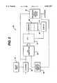
- FIG. 2is a block diagram of a microprocessor based controller to calculate a time based state of charge for cells in the battery pack of FIG. 1.
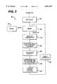
- FIG. 3is a flow chart showing a process for determining a state of charge.
- FIG. 4is a flow chart showing a process for determining an operational mode of a battery.
- FIG. 5is a flow chart showing a process for calculating capacity.
- a battery pack 10includes a case 12 carrying a display 14.
- the case 12houses rechargeable battery cells, a controller (as will be described in conjunction with FIG. 2) and an electrical terminal 16 for connection to a user appliance such as a cellular telephone, video camcorder, etc.
- the case 12can be configured to fit the user appliance.
- the case 12carries the display 14.
- the display 14includes a numeric message field which indicates, generally, in hours and minutes, the amount of time left to charge the battery, or to discharge the battery in accordance with the mode of operation of the battery. That is, the display will display a first time to discharge when the battery is in a use mode and a second time remaining to discharge when in a standby mode. These first and second times are determined in accordance with the capacity of the battery and the drain of charge from the battery depending on the mode. Alternatively, the display can display the time to charge the battery during charging operations.
- the display 14can have fields for displaying several status type messages.
- the display 14can have a field that indicates the current mode of operation of the battery.
- the "TALK" message 14ccan be displayed on a battery used in cellular telephones and indicates that the battery is connected to a phone currently in use, whereas, the "STDY,” message i.e., standby 14e, can be displayed when the battery is in a standby mode of operation.
- the batterycan display messages such as "FULL CHARGE NEEDED" 14f, "REPLACE SOON” 14g and "INT EXT” 14a that can be used to indicate whether an internal or external charger in being used.
- the display 14can display the time "TO FULL CHARGE", and so forth.
- the microprocessor based controller 20for generating signals to cause appropriate messages to be displayed on display 14 is shown.
- the microprocessor based controller 20includes a processor 22 fed via a memory 24 having a computer program 40 in the form of software or firmware stored therein which controls operation of the processor 22 and permits the processor 22 to cause measurements of energy being removed from a rechargeable battery cell or being added to a rechargeable battery cell 36. These measurements are used to ascertain the amount of time that the battery cells have for discharging and charging in accordance with the maximum capacity of the battery cells, and either the rate of charge, or the rate of discharge of the battery cells in accordance with the mode or use, i.e., talk or a standby mode.
- leakage of charge from the batterycan also calculated. Charge leakage can be based on known or estimated leakage rates.
- the processorcontrols an A/D converter 26 that provides data corresponding to measurements made of the state of the battery cells 36.
- the A/D converter 26senses current fed to the battery cells via a charger 30 and also senses current drawn from the rechargeable battery cell via an energy monitor circuit 28.
- the energy monitoring circuitcan operate using various known modes. A preferred mode is the so-called "Coulomb counting mode" in which charge that is removed from the battery is determined. Under control of the program 40, the A/D converter will sample these signals and feed these signals to the processor 22 to permit the processor to make the necessary measurements of these parameters.
- the controller 20 as well as chargingcan be performed via a solar panel 32.
- the rechargeable battery cells 36can supply current to the controller electronics 20.
- the program 40includes an initialization routine 42 which initializes various components in the controller 20, as needed.
- the controller 20will enter a sleep mode 24 and will remain in that mode unless awakened by a timer signal 43 or some other event.
- the program 40can exit the sleep mode via an interrupt from the energy monitoring circuit or from software or hardware timers.
- the programcauses the processor to read 46 outputs from the analog-to-digital converter (26, FIG. 2).
- the A/D converter(26, FIG. 2) will be fed via the discharge current from the rechargeable battery cells 36 via the energy monitoring circuit 28, as well as, a charging current from the charger 30 depending upon the use of the battery.
- the processorwill determine the mode of operation 48 of the battery and call an average current routine that will calculate the average current being drawn from the battery over a period of time. Details on one approach for determining mode of operation are set out in FIG. 4.
- the processorwill calculate 50 the remaining capacity of the battery (using a routine 80 FIG. 5, or equivalent) and will determine the end of charge and end of discharge states of the battery 36.
- the processorwill calculate the time remaining to discharge or charge the battery in accordance with the mode of operation of the battery and produce signals that are used by a display control routine to enable the various messages 14a-14g on the display 14. Thereafter, the processor resets the operation and returns to a sleep mode 34 awaiting the next event.
- the process 48 for determining the mode of operation of the battery 10includes determining 60 a direction of current flow from the battery.
- the direction of current flowdetermines whether the battery is in a use or standby state, or in a charging state. If the direction of current flow is negative, i.e., the battery is being discharged, the process will determine 62 if the current being drawn from the battery exceeds some predetermined threshold for a specified period of time.
- batteries used in cellular telephones or video camcordershave maximum standby currents that can exceed the minimum use currents. Therefore, in order to provide accurate representations of the amount of time available in each mode, it is necessary to filter the current consumption and add current consumption to the proper mode.
- the process 48determines 62 the amount of current drawn from the battery over a specified period of time. This assumes that the peak currents are exceeded for a specified period of time in a "use" mode; whereas those peak currents are not exceeded over a long period of time during standby mode.
- the processdetermines 62 that the currents do exceed some threshold for a specified period of time, that indicates that the battery is in a "use” mode such as a "talk" mode for a cellular telephone. Therefore, the current consumed in the "use" mode, i.e., talk, is summed 66 with previous use currents and the time spent in that mode is also incremented. If the threshold was not exceeded for the specified period of time, the battery is in a standby mode and standby currents are added 68 and time in that mode is incremented.
- the mode detection process 48calculates 72 an average current by dividing total current by the total time in which the battery has been operated.
- the mode detection process 48then calls a time remaining calculation process 80.
- the time remaining process 80determines the amount of time remaining to fully discharge the battery or charge the battery depending upon the mode of operation, as determined in FIG. 4.
- One modelis a floating average technique in which a moving average of current consumption is calculated separately for the current when the battery is in a "use" mode or a "standby" mode.
- One disadvantage with this approachis that since the process is a moving average, the amount of time to discharge may in fact go up when an average current value goes down relatively quickly. To dampen this effect, a non-floating average can be used in which the average current is updated over very large time intervals with actually learned values. This model provides a smoother output because the amount of current used in the calculations is constant during a calculation cycle.
- An alternative modelis a time count model.
- a time count registeris decremented to count down the amount of time remaining in the time count register. This technique provides a precise count of time that the battery spends in the various modes.
- the time count model embodiment of the remaining time calculation 80calculates 82 the remaining time to discharge the battery once per charging cycle and initializes 84 a pair "time remaining to discharge registers" (not shown) with the time value corresponding to the amount of time needed to discharge the battery in accordance with each mode such as "USE” e.g., talk and "STB” e.g., standby, as in Equations 1 and 2.
- the remaining timeis calculated 86 by dividing the capacity of the battery by the average current consumed per time period.
- the use and standby mode time registerscontain the remaining time to discharge the battery in accordance with the mode. As a mode is determined 86, each mode register is decremented. Thus for the standby mode, the mode standby register is decremented as in Equation 3, and the use mode register is decremented as in Equation 4.
- the processdecrements the standby register, as given in Equation 5 and decrements the use register by an amount of time, as given by Equation 6.
Landscapes
- Engineering & Computer Science (AREA)
- Manufacturing & Machinery (AREA)
- Chemical & Material Sciences (AREA)
- Chemical Kinetics & Catalysis (AREA)
- Electrochemistry (AREA)
- General Chemical & Material Sciences (AREA)
- Power Engineering (AREA)
- Charge And Discharge Circuits For Batteries Or The Like (AREA)
- Secondary Cells (AREA)
- Tests Of Electric Status Of Batteries (AREA)
- Battery Mounting, Suspending (AREA)
Abstract
Description
This invention relates to batteries for portable devices such as computers, camcorders and cellular phones.
Batteries are used to power portable electronic equipment. Often batteries are used with equipment that give an indication of an amount of charge left in the battery. The charge indicator displays an indication of a percentage of useful power remaining compared to that the full charged battery. Sometimes these indicators are carried by the battery cell and are often of the chemical type. Sometimes the indicators are produced by circuits contained in the electronic device such as the cell phone or the like. When the indicator is produced by the device, the indicator is often a display such as an LCD display of a battery divided into segments. Each segment is lit or enabled to represent a percentage of power left in the battery. As power is drained from the battery segments are turned off with remaining lit ones indicating the remaining power in the battery.
According to an aspect of the invention, a battery pack for a portable electronic device includes a case for carrying a battery. The case supports a charge sensing circuit carried by the case, the charge sensing circuit producing a discharge signal corresponding to a measurement of an amount of charge removed from a battery. The case also supports a processor responsive to the discharge signal from the charge sensor circuit to produce a signal corresponding to an amount of time prior to discharge of the battery based on a current rate of discharge and a display responsive to the signal to display a time period corresponding to the amount of time to discharge the battery based upon the current rate of discharge of the battery.
The battery pack can include a charge sensor circuit that measures the amount of charge removed from the battery. The sensor circuit can be a Coulomb counting circuit that counts an amount of charge units removed from the battery. The display can be a liquid crystal display, electrophoretic, or electronic ink display. The battery pack can carry at least one battery cell within the case. The processor is responsive to a charge signal and produces the signal corresponding to an amount of time prior to discharge based on the charge signal and a discharge signal from the charge sensor circuit. The processor produces a signal corresponding to a message that indicates a mode of operation of the battery and the message is displayed by the display. The message can correspond to an operation mode or a diagnostic mode.
According to another aspect of the invention, a battery pack for a portable electronic device includes a case carrying a battery, the case supporting a charge sensing circuit to produce an electrical signal corresponding to a measurement of an amount of charge removed from the battery and a processor responsive to the electrical signal from the charge sensor circuit to produce a signal corresponding to an amount of time prior to discharge of the battery in accordance with a history of operation of the battery. The battery pack also includes a display responsive to the signal indicating the amount of time prior to discharge, to display a time period corresponding to the amount of time to discharge the battery based upon a current mode of operation of the battery.
According to a still further aspect of the invention, a method of indicating time remaining to discharge a battery includes measuring and accumulating an amount of charge removed from the battery, determining the time remaining to discharge the battery from the amount of accumulated charge removed from the battery and from a current mode of operation of the battery and displaying a time period corresponding to the amount of time to discharge the battery.
According to a still further aspect of the invention, a method of indicating time remaining to charge a battery contained in a battery case includes measuring and accumulating an amount of charge inserted into the battery during charging of the battery and determining the time remaining to charge the battery from the amount of accumulated charge inserted into the battery. The method also includes displaying, on a display carried by the battery case, a time period corresponding to the amount of time to charge the battery.
One or more of the following advantages are provided by the invention. The display can have fields for displaying several status type messages. The processor can cause measurements of charge being removed from a rechargeable battery cell or being added to a rechargeable battery cell. These measurements are used to determine the amount of time that the battery cells have for discharging and charging. The time is calculated in accordance with the maximum capacity of the battery cells, and either the rate of charge or the rate of discharge of the battery cells in accordance with the mode of use, i.e., talk or a standby mode. This simplifies a user's estimate of the ability of the battery to last for a particular use before reaching discharge. Further, because the display is on the battery, its time to discharge can be ascertained by a user without having to attach the battery to a device such as a camcorder or cell phone.
FIG. 1 is a perspective view of a battery pack carrying a display.
FIG. 2 is a block diagram of a microprocessor based controller to calculate a time based state of charge for cells in the battery pack of FIG. 1.
FIG. 3 is a flow chart showing a process for determining a state of charge.
FIG. 4 is a flow chart showing a process for determining an operational mode of a battery.
FIG. 5 is a flow chart showing a process for calculating capacity.
Referring now to FIG. 1, abattery pack 10 includes acase 12 carrying adisplay 14. Thecase 12 houses rechargeable battery cells, a controller (as will be described in conjunction with FIG. 2) and anelectrical terminal 16 for connection to a user appliance such as a cellular telephone, video camcorder, etc. Thecase 12 can be configured to fit the user appliance. Thecase 12 carries thedisplay 14. Thedisplay 14 includes a numeric message field which indicates, generally, in hours and minutes, the amount of time left to charge the battery, or to discharge the battery in accordance with the mode of operation of the battery. That is, the display will display a first time to discharge when the battery is in a use mode and a second time remaining to discharge when in a standby mode. These first and second times are determined in accordance with the capacity of the battery and the drain of charge from the battery depending on the mode. Alternatively, the display can display the time to charge the battery during charging operations.
Thedisplay 14 can have fields for displaying several status type messages. In particular, thedisplay 14 can have a field that indicates the current mode of operation of the battery. For example, the "TALK"message 14c can be displayed on a battery used in cellular telephones and indicates that the battery is connected to a phone currently in use, whereas, the "STDY," message i.e.,standby 14e, can be displayed when the battery is in a standby mode of operation. In addition, the battery can display messages such as "FULL CHARGE NEEDED" 14f, "REPLACE SOON" 14g and "INT EXT" 14a that can be used to indicate whether an internal or external charger in being used. Thedisplay 14 can display the time "TO FULL CHARGE", and so forth.
Referring now to FIG. 2, a microprocessor basedcontroller 20 for generating signals to cause appropriate messages to be displayed ondisplay 14 is shown. The microprocessor basedcontroller 20 includes aprocessor 22 fed via amemory 24 having acomputer program 40 in the form of software or firmware stored therein which controls operation of theprocessor 22 and permits theprocessor 22 to cause measurements of energy being removed from a rechargeable battery cell or being added to arechargeable battery cell 36. These measurements are used to ascertain the amount of time that the battery cells have for discharging and charging in accordance with the maximum capacity of the battery cells, and either the rate of charge, or the rate of discharge of the battery cells in accordance with the mode or use, i.e., talk or a standby mode. Optionally, leakage of charge from the battery can also calculated. Charge leakage can be based on known or estimated leakage rates.
The processor controls an A/D converter 26 that provides data corresponding to measurements made of the state of thebattery cells 36. The A/D converter 26 senses current fed to the battery cells via acharger 30 and also senses current drawn from the rechargeable battery cell via anenergy monitor circuit 28. The energy monitoring circuit can operate using various known modes. A preferred mode is the so-called "Coulomb counting mode" in which charge that is removed from the battery is determined. Under control of theprogram 40, the A/D converter will sample these signals and feed these signals to theprocessor 22 to permit the processor to make the necessary measurements of these parameters. Optionally, thecontroller 20 as well as charging can be performed via asolar panel 32. Alternatively, therechargeable battery cells 36 can supply current to thecontroller electronics 20.
Referring now to FIG. 3, aprogram 40 for providing a time state of charge display format for thedisplay 14 is shown. Theprogram 40 includes aninitialization routine 42 which initializes various components in thecontroller 20, as needed. Thecontroller 20 will enter asleep mode 24 and will remain in that mode unless awakened by atimer signal 43 or some other event. For example, theprogram 40 can exit the sleep mode via an interrupt from the energy monitoring circuit or from software or hardware timers. Upon exiting the sleep mode, the program causes the processor to read 46 outputs from the analog-to-digital converter (26, FIG. 2). The A/D converter (26, FIG. 2) will be fed via the discharge current from therechargeable battery cells 36 via theenergy monitoring circuit 28, as well as, a charging current from thecharger 30 depending upon the use of the battery.
The processor will determine the mode ofoperation 48 of the battery and call an average current routine that will calculate the average current being drawn from the battery over a period of time. Details on one approach for determining mode of operation are set out in FIG. 4. The processor will calculate 50 the remaining capacity of the battery (using a routine 80 FIG. 5, or equivalent) and will determine the end of charge and end of discharge states of thebattery 36. The processor will calculate the time remaining to discharge or charge the battery in accordance with the mode of operation of the battery and produce signals that are used by a display control routine to enable thevarious messages 14a-14g on thedisplay 14. Thereafter, the processor resets the operation and returns to a sleep mode 34 awaiting the next event.
Referring now to FIG. 4, theprocess 48 for determining the mode of operation of thebattery 10 includes determining 60 a direction of current flow from the battery. The direction of current flow determines whether the battery is in a use or standby state, or in a charging state. If the direction of current flow is negative, i.e., the battery is being discharged, the process will determine 62 if the current being drawn from the battery exceeds some predetermined threshold for a specified period of time. Often batteries used in cellular telephones or video camcorders have maximum standby currents that can exceed the minimum use currents. Therefore, in order to provide accurate representations of the amount of time available in each mode, it is necessary to filter the current consumption and add current consumption to the proper mode. Therefore, theprocess 48 determines 62 the amount of current drawn from the battery over a specified period of time. This assumes that the peak currents are exceeded for a specified period of time in a "use" mode; whereas those peak currents are not exceeded over a long period of time during standby mode.
If the process determines 62 that the currents do exceed some threshold for a specified period of time, that indicates that the battery is in a "use" mode such as a "talk" mode for a cellular telephone. Therefore, the current consumed in the "use" mode, i.e., talk, is summed 66 with previous use currents and the time spent in that mode is also incremented. If the threshold was not exceeded for the specified period of time, the battery is in a standby mode and standby currents are added 68 and time in that mode is incremented.
If the direction of current flow was into the battery or if there is no current flow, those occurrences indicate that the battery is in an "off" state or a "charging" state. In the off state, the battery may still have a small negative current flow and such currents and corresponding times are added 74. The use or talk mode current, standby current and off state currents are added 70 to provide a total current that is used to calculate an average current 72.
Themode detection process 48 calculates 72 an average current by dividing total current by the total time in which the battery has been operated. Themode detection process 48 then calls a time remainingcalculation process 80. Thetime remaining process 80 determines the amount of time remaining to fully discharge the battery or charge the battery depending upon the mode of operation, as determined in FIG. 4.
Several time remaining models may be used. One model is a floating average technique in which a moving average of current consumption is calculated separately for the current when the battery is in a "use" mode or a "standby" mode. One disadvantage with this approach is that since the process is a moving average, the amount of time to discharge may in fact go up when an average current value goes down relatively quickly. To dampen this effect, a non-floating average can be used in which the average current is updated over very large time intervals with actually learned values. This model provides a smoother output because the amount of current used in the calculations is constant during a calculation cycle.
An alternative model is a time count model. In the time count model, a time count register is decremented to count down the amount of time remaining in the time count register. This technique provides a precise count of time that the battery spends in the various modes.
Referring now to FIG. 5, the time count model embodiment of the remainingtime calculation 80 calculates 82 the remaining time to discharge the battery once per charging cycle and initializes 84 a pair "time remaining to discharge registers" (not shown) with the time value corresponding to the amount of time needed to discharge the battery in accordance with each mode such as "USE" e.g., talk and "STB" e.g., standby, as in Equations 1 and 2.
REMT,USE=CAP/Iavg,USE Equation 1
REMT,STB=CAP/Iavg,STB Equation 2
The remaining time is calculated 86 by dividing the capacity of the battery by the average current consumed per time period. The use and standby mode time registers contain the remaining time to discharge the battery in accordance with the mode. As a mode is determined 86, each mode register is decremented. Thus for the standby mode, the mode standby register is decremented as in Equation 3, and the use mode register is decremented as in Equation 4.
RemT,STB=RemT,USE-1/min Equation 3
RemT,TLK=RemT,TLK-Iavg,STB/Iave,USE/min Equation 4
If the mode detected 86 is the use mode, the process decrements the standby register, as given in Equation 5 and decrements the use register by an amount of time, as given by Equation 6.
RemT,STB=RemT,STB-Iavg,USE/Iave,STB/min Equation 5
RemT,USE=RemT,USE-1/min Equation 6
It is to be understood that while the invention has been described in conjunction with the detailed description thereof, the foregoing description is intended to illustrate and not limit the scope of the invention, which is defined by the scope of the appended claims. Other aspects, advantages, and modifications are within the scope of the following claims.
Claims (20)
1. A battery pack for a portable electronic device comprising:
a case for carrying a battery, said case supporting:
a charge sensing circuit, the charge sensing circuit producing a discharge signal corresponding to a measurement of an amount of charge removed from a battery;
a processor responsive to the discharge signal from the charge sensor circuit to produce a signal corresponding to an amount of time prior to discharge of the battery based on a current rate of discharge of the battery; and
a display responsive to the signal corresponding to the amount of time to discharge the battery, configured to display a time period corresponding to the amount of time to discharge the battery based upon the current rate of discharge of the battery.
2. The battery pack of claim 1 wherein the sensor circuit is a charge sensor circuit that measures the amount of charge removed from the battery.
3. The battery pack of claim 1 wherein the sensor circuit is a Coulomb counting circuit that counts an amount of charge units removed from the battery.
4. The battery pack of claim 1 wherein the display is a low power display.
5. The battery pack of claim 1 wherein the display is a liquid crystal display, an electrophoretic display or an electronic ink display.
6. The battery pack of claim 1 further comprising at least one battery cell carried within the case.
7. The battery pack of claim 1 wherein the charge sensing circuit produces a charge signal corresponding to the amount of charge fed to a battery during a charging mode of operation.
8. The battery pack of claim 7 wherein the processor is responsive to the charge signal and produces said signal corresponding to an amount of time prior to discharge based on the charge signal and the discharge signal from the charge sensor circuit.
9. The battery pack of claim 1 wherein the processor produces a signal corresponding to a message that indicates a mode of operation of the battery and the message is displayed by the display device.
10. The battery pack of claim 9 wherein the message corresponds to an operation mode or a standby mode.
11. The battery pack of claim 1 wherein the battery pack further comprises:
a battery and the charge sensing circuit and processor derive a power signal from the battery.
12. A battery pack for a portable electronic device comprises:
a case carrying a battery, the case supporting:
a charge sensing circuit to produce an electrical signal corresponding to a measurement of an amount of charge removed from the battery;
a processor responsive to the electrical signal from the charge sensor circuit to produce a signal corresponding to an amount of time prior to discharge of the battery in accordance with a history of operation of the battery; and
a display, responsive to the signal indicating the amount of time prior to discharge, to display a time period corresponding to the amount of time to discharge the battery based upon a current mode of operation of the battery.
13. The battery pack of claim 12 wherein the sensor circuit is a charge sensor circuit that measures the amount of charge removed from the battery.
14. The battery pack of claim 12 wherein the sensor circuit is a Coulomb counting circuit that counts the amount of charge removed from the battery.
15. The battery pack of claim 12 wherein the display is a liquid crystal display, a light emitting diode display, an electrophoretic display or an electronic ink display.
16. A method of indicating time remaining to discharge a battery contained in a battery case, the method comprising:
measuring and accumulating an amount of charge removed from the battery;
determining the time remaining to discharge the battery from the amount of accumulated charge removed from the battery; and
displaying, on a display carried by the battery case, a time period corresponding to the amount of time to discharge the battery.
17. The method of claim 16 wherein the time displayed is based upon a current mode of operation of the battery.
18. The method of claim 16 wherein measuring and accumulating an amount of charge removed from the battery takes into consideration charge removed during operation, standby and quiescent periods.
19. A method of indicating time remaining to charge a battery contained in a battery case, the method comprising:
measuring and accumulating an amount of charge inserted into the battery during charging of the battery;
determining the time remaining to charge the battery from the amount of accumulated charge inserted into the battery; and
displaying, on a display carried by the battery case, a time period corresponding to the amount of time to charge the battery.
20. The method of claim 19 wherein the time displayed is based upon a current mode of operation of the battery.
Priority Applications (10)
| Application Number | Priority Date | Filing Date | Title |
|---|---|---|---|
| US09/176,574US6051957A (en) | 1998-10-21 | 1998-10-21 | Battery pack having a state of charge indicator |
| JP2000577499AJP2002528850A (en) | 1998-10-21 | 1999-10-20 | Battery pack having charge status indicator |
| DE69924860TDE69924860T2 (en) | 1998-10-21 | 1999-10-20 | BATTERY WITH CHARGE INDICATOR |
| CNB998133434ACN1201162C (en) | 1998-10-21 | 1999-10-20 | Battery pack having state charging indicator |
| PCT/US1999/024470WO2000023810A1 (en) | 1998-10-21 | 1999-10-20 | Battery pack having a state of charge indicator |
| EP99955060AEP1123515B1 (en) | 1998-10-21 | 1999-10-20 | Battery pack having a state of charge indicator |
| AT99955060TATE293798T1 (en) | 1998-10-21 | 1999-10-20 | BATTERY WITH CHARGE INDICATOR |
| AU11251/00AAU1125100A (en) | 1998-10-21 | 1999-10-20 | Battery pack having a state of charge indicator |
| CA002349570ACA2349570A1 (en) | 1998-10-21 | 1999-10-20 | Battery pack having a state of charge indicator |
| ARP990105315AAR025810A1 (en) | 1998-10-21 | 1999-10-21 | BATTERY ASSEMBLY FOR A PORTABLE ELECTRONIC DEVICE, REMOTE TIME INDICATION METHOD UNTIL THE DISCHARGE OF A BATTERY CONTAINED IN AN ACCOMMODATION, AND A TIME INDICATION METHOD TO TRANSCENT UNTIL CHARGING A BATTERY CONTAINED IN AN ACCOMMODATION |
Applications Claiming Priority (1)
| Application Number | Priority Date | Filing Date | Title |
|---|---|---|---|
| US09/176,574US6051957A (en) | 1998-10-21 | 1998-10-21 | Battery pack having a state of charge indicator |
Publications (1)
| Publication Number | Publication Date |
|---|---|
| US6051957Atrue US6051957A (en) | 2000-04-18 |
Family
ID=22644912
Family Applications (1)
| Application Number | Title | Priority Date | Filing Date |
|---|---|---|---|
| US09/176,574Expired - LifetimeUS6051957A (en) | 1998-10-21 | 1998-10-21 | Battery pack having a state of charge indicator |
Country Status (10)
| Country | Link |
|---|---|
| US (1) | US6051957A (en) |
| EP (1) | EP1123515B1 (en) |
| JP (1) | JP2002528850A (en) |
| CN (1) | CN1201162C (en) |
| AR (1) | AR025810A1 (en) |
| AT (1) | ATE293798T1 (en) |
| AU (1) | AU1125100A (en) |
| CA (1) | CA2349570A1 (en) |
| DE (1) | DE69924860T2 (en) |
| WO (1) | WO2000023810A1 (en) |
Cited By (46)
| Publication number | Priority date | Publication date | Assignee | Title |
|---|---|---|---|---|
| US20020018137A1 (en)* | 2000-07-25 | 2002-02-14 | Nikon Corporation | Electronic camera |
| US6411911B1 (en)* | 1999-06-30 | 2002-06-25 | Tyco Electronics Logistics Ag | Battery diagnostic method utilizing a universal normalized discharge curve for predicting battery reserve time |
| US6501968B1 (en)* | 1997-04-21 | 2002-12-31 | Canon Kabushiki Kaisha | Battery-powered communications apparatus |
| US20030011372A1 (en)* | 2001-06-19 | 2003-01-16 | Stmicroelectronics S.A. | Method and device for checking the charge state of a battery, in particular a rechargeable battery for a cellular mobile telephone |
| US6512354B2 (en)* | 1998-07-08 | 2003-01-28 | E Ink Corporation | Method and apparatus for sensing the state of an electrophoretic display |
| US6580665B1 (en)* | 1998-08-31 | 2003-06-17 | Citizen Watch Co., Ltd. | Electronic timepiece having power generating function |
| US20030195719A1 (en)* | 2002-04-10 | 2003-10-16 | Hitachi, Ltd. | State detecting system and device employing the same |
| US6658270B1 (en)* | 2000-08-18 | 2003-12-02 | Chang-Jung Lee | Displayer-embedded cellular phone battery |
| US6704133B2 (en) | 1998-03-18 | 2004-03-09 | E-Ink Corporation | Electro-optic display overlays and systems for addressing such displays |
| US20040070511A1 (en)* | 2002-10-11 | 2004-04-15 | Samsung Electronics Co., Ltd. | Method for informing user of available battery time based on operating mode of hybrid terminal |
| US20040164710A1 (en)* | 2003-02-21 | 2004-08-26 | Mcneill James Thomas | Battery charging apparatus |
| US20040239293A1 (en)* | 2003-04-01 | 2004-12-02 | Makita Corporation | Rechargeable battery devices |
| US6864875B2 (en) | 1998-04-10 | 2005-03-08 | E Ink Corporation | Full color reflective display with multichromatic sub-pixels |
| US20050099672A1 (en)* | 1998-07-08 | 2005-05-12 | E Ink Corporation | Method and apparatus for determining properties of an electrophoretic display |
| US20050275551A1 (en)* | 2004-06-14 | 2005-12-15 | John Houldsworth | Method and apparatus for brightness control of indication lights |
| US20060002220A1 (en)* | 2004-07-02 | 2006-01-05 | Seagate Technology Llc | Assessing energy requirements for a refreshed device |
| US20060187072A1 (en)* | 2005-02-23 | 2006-08-24 | Eaglepicher Energy Products Corporation | Physical key to facilitate an inactive mode for a state-of-charge indicator within a battery |
| US7140546B1 (en)* | 2002-12-12 | 2006-11-28 | Symbol Technologies, Inc. | Battery pack with integrated human interface devices |
| US7167155B1 (en) | 1995-07-20 | 2007-01-23 | E Ink Corporation | Color electrophoretic displays |
| US20070018615A1 (en)* | 2004-07-13 | 2007-01-25 | Siemens Aktiengesellschaft | Device and method for determining operating parameters of a battery |
| US20070035273A1 (en)* | 2005-08-11 | 2007-02-15 | Fujitsu Limited | Electronic apparatus with battery unit |
| US20080136654A1 (en)* | 2006-12-12 | 2008-06-12 | Motorola, Inc. | Methods and devices for power source life value calculation and representation |
| US20080169179A1 (en)* | 2006-12-21 | 2008-07-17 | Strangfeld Bruce A | Switch actuator |
| US20080306699A1 (en)* | 2004-07-23 | 2008-12-11 | Zte Corpoaration | Method For Measuring the Power Consumption Time of a Cdma Mobile Terminal |
| US20090033284A1 (en)* | 2007-05-04 | 2009-02-05 | Iwei Technology Co., Ltd. | Charging device with battery capacity analysis function |
| US20090058368A1 (en)* | 2007-09-05 | 2009-03-05 | Black & Decker Inc. | System and method for re-initiating charge cycle for battery pack left in a charger |
| US20090249095A1 (en)* | 2008-03-26 | 2009-10-01 | Rajesh Poornachandran | User driven power conservation in processor-based systems |
| US20090273309A1 (en)* | 2008-04-30 | 2009-11-05 | Visteon Global Technologies, Inc. | Photovoltaic charging system |
| US20100198537A1 (en)* | 2008-12-26 | 2010-08-05 | Panasonic Corporation | Electronic device and method for calculating remaining usable time of battery |
| US20100253285A1 (en)* | 2009-04-03 | 2010-10-07 | Sony Corporation | Battery pack and charging method |
| WO2011029113A1 (en) | 2009-09-10 | 2011-03-17 | Fronius International Gmbh | Energy conversion method and apparatus, and welding device |
| WO2011061682A3 (en)* | 2009-11-17 | 2011-08-11 | Steve Carkner | Automatic flight-safe indicator and method of use for batteries |
| EP2487498A4 (en)* | 2009-10-06 | 2013-03-27 | Viva Developments S L | Device for digitally displaying the electric charge stored in electricity storage devices |
| US20140055082A1 (en)* | 2012-08-23 | 2014-02-27 | Qualcomm Incorporated | Charging current calibration |
| US20150281625A1 (en)* | 2014-03-31 | 2015-10-01 | Echostar Technologies L.L.C. | Predicting end of battery life for a remote controller device |
| US20150318720A1 (en)* | 2012-12-07 | 2015-11-05 | Hitachi Koki Co., Ltd. | Charging Device |
| US20160064962A1 (en)* | 2014-09-03 | 2016-03-03 | Mophie, Inc. | Systems and methods for battery charging and management |
| US9876522B2 (en) | 2013-03-15 | 2018-01-23 | Mophie, Inc. | Protective case for mobile device |
| US10170738B2 (en) | 2008-01-18 | 2019-01-01 | Mophie Inc. | Battery pack for mobile devices |
| US10416753B1 (en)* | 2015-12-10 | 2019-09-17 | Amazon Technologies, Inc. | Date-based computing device charge management |
| US10429917B2 (en)* | 2017-04-21 | 2019-10-01 | Dell Products L.P. | Calculating a throttle rate for battery current limiting |
| USD861653S1 (en) | 2015-05-27 | 2019-10-01 | Mophie Inc. | Protective battery case for mobile communications device |
| US10516431B2 (en) | 2017-11-21 | 2019-12-24 | Mophie Inc. | Mobile device case for receiving wireless signals |
| USD940647S1 (en) | 2019-01-07 | 2022-01-11 | Mophie Inc. | Battery pack |
| US11857482B1 (en) | 2013-07-01 | 2024-01-02 | Hyperice Ip Subco, Llc | Massage device having variable stroke length |
| US12343302B2 (en) | 2021-08-13 | 2025-07-01 | Hyperice Ip Subco, Llc | Combination applicator and adapter for percussive massage device |
Families Citing this family (8)
| Publication number | Priority date | Publication date | Assignee | Title |
|---|---|---|---|---|
| US20080042861A1 (en)* | 2006-08-16 | 2008-02-21 | Bruno Dacquay | Safety battery meter system for surgical hand piece |
| FR2916049B1 (en)* | 2007-05-11 | 2009-07-03 | Commissariat Energie Atomique | METHOD FOR DIAGNOSING DEFECTIVE ELEMENTS IN AN AUTONOMOUS SYSTEM POWERED BY AN INTERMITTENT POWER SOURCE |
| DE102010010443A1 (en)* | 2010-02-25 | 2011-08-25 | Dr. Ing. h.c. F. Porsche Aktiengesellschaft, 70435 | Display device of a motor vehicle |
| JP5108964B2 (en)* | 2011-01-14 | 2012-12-26 | 株式会社エヌ・ティ・ティ・ドコモ | Apparatus and method for calculating battery life of mobile device |
| FR2975543B1 (en)* | 2011-05-19 | 2015-01-02 | Renault Sa | SYSTEM AND METHOD FOR ESTIMATING THE END OF CHARGE OF A BATTERY |
| EP3033627A1 (en)* | 2013-08-13 | 2016-06-22 | Koninklijke Philips N.V. | Automated battery indication and feedback system based on environmental conditions and use data for improved management and reliability |
| CN111257781A (en)* | 2020-03-17 | 2020-06-09 | 上海度普新能源科技有限公司 | Power-off sleep resting time determination method, health state value determination method and health state value determination device |
| KR102554673B1 (en)* | 2020-10-13 | 2023-07-13 | 삼성에스디아이 주식회사 | Battery pack |
Citations (36)
| Publication number | Priority date | Publication date | Assignee | Title |
|---|---|---|---|---|
| US1497388A (en)* | 1922-11-03 | 1924-06-10 | Edward M Sterling | Method of and apparatus for indicating the electrical condition of a cell |
| US2980754A (en)* | 1959-03-23 | 1961-04-18 | Union Carbide Corp | Cell exhaustion indicator |
| US3563806A (en)* | 1967-12-11 | 1971-02-16 | Wayne R Hruden | Battery capacity and activation indicating structure |
| US4295097A (en)* | 1979-05-07 | 1981-10-13 | Arthur H. Thompson | Battery capacity measuring method and apparatus |
| US4323849A (en)* | 1980-01-11 | 1982-04-06 | Hybricon, Inc. | Coulometer |
| US4497881A (en)* | 1983-01-31 | 1985-02-05 | Bertolino Renee Z | Battery charge indicator |
| US4515873A (en)* | 1983-07-28 | 1985-05-07 | Cordis Corporation | Lithium cell having continuous depletion gauge |
| US4595880A (en)* | 1983-08-08 | 1986-06-17 | Ford Motor Company | Battery state of charge gauge |
| US4679000A (en)* | 1985-06-20 | 1987-07-07 | Robert Clark | Bidirectional current time integration device |
| US4952862A (en)* | 1989-09-29 | 1990-08-28 | At&T Bell Laboratories | Apparatus and method for adaptively predicting battery discharge reserve time |
| US5216371A (en)* | 1989-06-12 | 1993-06-01 | Ricoh Company, Ltd. | Battery pack including measuring and indicating |
| US5244754A (en)* | 1991-06-04 | 1993-09-14 | Display Matrix Corporation | Battery charge indicator |
| US5250905A (en)* | 1991-09-24 | 1993-10-05 | Duracell Inc. | Battery with electrochemical tester |
| US5254951A (en)* | 1991-05-29 | 1993-10-19 | Fujitsu Limited | Circuit for measuring discharging and charging current of a battery providing offset/drift voltage for correcting amplifier output |
| US5256500A (en)* | 1991-01-28 | 1993-10-26 | Mitsubishi Denki Kabushiki Kaisha | Battery having lifetime indicator |
| US5284719A (en)* | 1992-07-08 | 1994-02-08 | Benchmarq Microelectronics, Inc. | Method and apparatus for monitoring battery capacity |
| US5321627A (en)* | 1992-03-11 | 1994-06-14 | Globe-Union, Inc. | Battery monitor and method for providing operating parameters |
| US5341084A (en)* | 1991-12-12 | 1994-08-23 | Fujitsu Limited | Method and device for determining and indicating a residual capacity of a battery |
| US5348813A (en)* | 1991-06-04 | 1994-09-20 | Display Matrix Corporation | Battery charge indicator |
| US5371682A (en)* | 1993-02-04 | 1994-12-06 | At&T Corp. | Method and apparatus for predicting battery reserve time to a specified end-voltage |
| US5372898A (en)* | 1994-02-17 | 1994-12-13 | The United States Of America As Represented By The Secretary Of The Army | Universal inexpensive battery state-of-charge indicator |
| US5411817A (en)* | 1990-08-11 | 1995-05-02 | Eastman Kodak Company | Battery with charge indicator |
| US5418085A (en)* | 1991-01-31 | 1995-05-23 | Eveready Battery Company, Inc. | Battery voltage tester for end of cell |
| US5418086A (en)* | 1993-08-09 | 1995-05-23 | Eveready Battery Company, Inc. | Battery with coulometric state of charge indicator |
| US5460902A (en)* | 1993-05-07 | 1995-10-24 | Parker; Robert | Temperature responsive battery tester |
| US5518835A (en)* | 1992-07-23 | 1996-05-21 | 4C Technologies Inc. | Device for indicating the residual capacity of secondary cells |
| US5543245A (en)* | 1993-03-15 | 1996-08-06 | Alcatel Converters | System and method for monitoring battery aging |
| US5563004A (en)* | 1995-03-21 | 1996-10-08 | Aer Energy Resources, Inc. | Rechargeable metal-air electrochemical cell with hydrogen recombination and end-of-charge indicator |
| US5572110A (en)* | 1994-12-15 | 1996-11-05 | Intel Corporation | Smart battery charger system |
| US5578915A (en)* | 1994-09-26 | 1996-11-26 | General Motors Corporation | Dynamic battery state-of-charge and capacity determination |
| US5623210A (en)* | 1994-03-23 | 1997-04-22 | Sanyo Electric Co., Ltd. | Current detector for detecting battery charge remaining |
| US5640150A (en)* | 1995-08-17 | 1997-06-17 | The United States Of America As Represented By The Secretary Of The Army | Resettable state-of-charge indicator for rechargeable batteries |
| US5641587A (en)* | 1995-12-15 | 1997-06-24 | Compaq Computer Corporation | Battery pack with a monitoring circuit for a known system |
| US5658682A (en)* | 1992-12-11 | 1997-08-19 | Honda Giken Kogyo Kabushiki Kaisha | Process for detecting remaining capacity of battery |
| US5710501A (en)* | 1994-11-10 | 1998-01-20 | Duracell, Inc. | Battery pack having a processor controlled battery operating system |
| US5757595A (en)* | 1996-04-10 | 1998-05-26 | Honda Giken Kogyo Kabushiki Kaisha | Apparatus for displaying battery charging of electric vehicle |
Family Cites Families (12)
| Publication number | Priority date | Publication date | Assignee | Title |
|---|---|---|---|---|
| JPS5421537A (en)* | 1977-07-18 | 1979-02-17 | Canon Kk | Electronic device |
| GB2213599B (en)* | 1986-01-14 | 1990-02-21 | Eikoh Giken Co Ltd | A circuit arrangement for judging the lifetime of a battery in a no-break power supply system |
| FR2615627A1 (en)* | 1987-05-21 | 1988-11-25 | Robotconsult Sarl | Device for analysing the available charge of storage batteries |
| US4835453A (en)* | 1987-07-07 | 1989-05-30 | U.S. Philips Corp. | Battery-powered device |
| JPH02171669A (en)* | 1988-12-23 | 1990-07-03 | Matsushita Electric Works Ltd | battery capacity display device |
| JPH0386744U (en)* | 1989-06-12 | 1991-09-03 | ||
| JPH0422073A (en)* | 1990-05-16 | 1992-01-27 | Casio Comput Co Ltd | Battery pack device and battery status notification device |
| US5315228A (en)* | 1992-01-24 | 1994-05-24 | Compaq Computer Corp. | Battery charge monitor and fuel gauge |
| JP3225580B2 (en)* | 1992-04-03 | 2001-11-05 | ソニー株式会社 | Battery device |
| JP3182248B2 (en)* | 1993-04-30 | 2001-07-03 | 三洋電機株式会社 | Battery pack and charger |
| US5726555A (en)* | 1995-02-28 | 1998-03-10 | Nec Corporation | Battery charger capable of displaying necessary charging time |
| JPH09167638A (en)* | 1995-12-15 | 1997-06-24 | Hitachi Ltd | Battery with remaining capacity display and battery pack with remaining capacity display function |
- 1998
- 1998-10-21USUS09/176,574patent/US6051957A/ennot_activeExpired - Lifetime
- 1999
- 1999-10-20JPJP2000577499Apatent/JP2002528850A/ennot_activeRevoked
- 1999-10-20WOPCT/US1999/024470patent/WO2000023810A1/enactiveIP Right Grant
- 1999-10-20AUAU11251/00Apatent/AU1125100A/ennot_activeAbandoned
- 1999-10-20DEDE69924860Tpatent/DE69924860T2/ennot_activeExpired - Lifetime
- 1999-10-20ATAT99955060Tpatent/ATE293798T1/ennot_activeIP Right Cessation
- 1999-10-20EPEP99955060Apatent/EP1123515B1/ennot_activeExpired - Lifetime
- 1999-10-20CNCNB998133434Apatent/CN1201162C/ennot_activeExpired - Fee Related
- 1999-10-20CACA002349570Apatent/CA2349570A1/ennot_activeAbandoned
- 1999-10-21ARARP990105315Apatent/AR025810A1/enunknown
Patent Citations (38)
| Publication number | Priority date | Publication date | Assignee | Title |
|---|---|---|---|---|
| US1497388A (en)* | 1922-11-03 | 1924-06-10 | Edward M Sterling | Method of and apparatus for indicating the electrical condition of a cell |
| US2980754A (en)* | 1959-03-23 | 1961-04-18 | Union Carbide Corp | Cell exhaustion indicator |
| US3563806A (en)* | 1967-12-11 | 1971-02-16 | Wayne R Hruden | Battery capacity and activation indicating structure |
| US4295097A (en)* | 1979-05-07 | 1981-10-13 | Arthur H. Thompson | Battery capacity measuring method and apparatus |
| US4323849A (en)* | 1980-01-11 | 1982-04-06 | Hybricon, Inc. | Coulometer |
| US4497881A (en)* | 1983-01-31 | 1985-02-05 | Bertolino Renee Z | Battery charge indicator |
| US4515873A (en)* | 1983-07-28 | 1985-05-07 | Cordis Corporation | Lithium cell having continuous depletion gauge |
| US4595880A (en)* | 1983-08-08 | 1986-06-17 | Ford Motor Company | Battery state of charge gauge |
| US4679000A (en)* | 1985-06-20 | 1987-07-07 | Robert Clark | Bidirectional current time integration device |
| US5216371A (en)* | 1989-06-12 | 1993-06-01 | Ricoh Company, Ltd. | Battery pack including measuring and indicating |
| US4952862A (en)* | 1989-09-29 | 1990-08-28 | At&T Bell Laboratories | Apparatus and method for adaptively predicting battery discharge reserve time |
| US5411817A (en)* | 1990-08-11 | 1995-05-02 | Eastman Kodak Company | Battery with charge indicator |
| US5256500A (en)* | 1991-01-28 | 1993-10-26 | Mitsubishi Denki Kabushiki Kaisha | Battery having lifetime indicator |
| US5418085A (en)* | 1991-01-31 | 1995-05-23 | Eveready Battery Company, Inc. | Battery voltage tester for end of cell |
| US5254951A (en)* | 1991-05-29 | 1993-10-19 | Fujitsu Limited | Circuit for measuring discharging and charging current of a battery providing offset/drift voltage for correcting amplifier output |
| US5244754A (en)* | 1991-06-04 | 1993-09-14 | Display Matrix Corporation | Battery charge indicator |
| US5348813A (en)* | 1991-06-04 | 1994-09-20 | Display Matrix Corporation | Battery charge indicator |
| US5396177A (en)* | 1991-09-24 | 1995-03-07 | Duracell Inc. | Battery with electrochemical tester |
| US5250905A (en)* | 1991-09-24 | 1993-10-05 | Duracell Inc. | Battery with electrochemical tester |
| US5339024A (en)* | 1991-09-24 | 1994-08-16 | Duracell Inc. | Battery with electrochemical tester |
| US5341084A (en)* | 1991-12-12 | 1994-08-23 | Fujitsu Limited | Method and device for determining and indicating a residual capacity of a battery |
| US5321627A (en)* | 1992-03-11 | 1994-06-14 | Globe-Union, Inc. | Battery monitor and method for providing operating parameters |
| US5284719A (en)* | 1992-07-08 | 1994-02-08 | Benchmarq Microelectronics, Inc. | Method and apparatus for monitoring battery capacity |
| US5518835A (en)* | 1992-07-23 | 1996-05-21 | 4C Technologies Inc. | Device for indicating the residual capacity of secondary cells |
| US5658682A (en)* | 1992-12-11 | 1997-08-19 | Honda Giken Kogyo Kabushiki Kaisha | Process for detecting remaining capacity of battery |
| US5371682A (en)* | 1993-02-04 | 1994-12-06 | At&T Corp. | Method and apparatus for predicting battery reserve time to a specified end-voltage |
| US5543245A (en)* | 1993-03-15 | 1996-08-06 | Alcatel Converters | System and method for monitoring battery aging |
| US5460902A (en)* | 1993-05-07 | 1995-10-24 | Parker; Robert | Temperature responsive battery tester |
| US5418086A (en)* | 1993-08-09 | 1995-05-23 | Eveready Battery Company, Inc. | Battery with coulometric state of charge indicator |
| US5372898A (en)* | 1994-02-17 | 1994-12-13 | The United States Of America As Represented By The Secretary Of The Army | Universal inexpensive battery state-of-charge indicator |
| US5623210A (en)* | 1994-03-23 | 1997-04-22 | Sanyo Electric Co., Ltd. | Current detector for detecting battery charge remaining |
| US5578915A (en)* | 1994-09-26 | 1996-11-26 | General Motors Corporation | Dynamic battery state-of-charge and capacity determination |
| US5710501A (en)* | 1994-11-10 | 1998-01-20 | Duracell, Inc. | Battery pack having a processor controlled battery operating system |
| US5572110A (en)* | 1994-12-15 | 1996-11-05 | Intel Corporation | Smart battery charger system |
| US5563004A (en)* | 1995-03-21 | 1996-10-08 | Aer Energy Resources, Inc. | Rechargeable metal-air electrochemical cell with hydrogen recombination and end-of-charge indicator |
| US5640150A (en)* | 1995-08-17 | 1997-06-17 | The United States Of America As Represented By The Secretary Of The Army | Resettable state-of-charge indicator for rechargeable batteries |
| US5641587A (en)* | 1995-12-15 | 1997-06-24 | Compaq Computer Corporation | Battery pack with a monitoring circuit for a known system |
| US5757595A (en)* | 1996-04-10 | 1998-05-26 | Honda Giken Kogyo Kabushiki Kaisha | Apparatus for displaying battery charging of electric vehicle |
Non-Patent Citations (2)
| Title |
|---|
| "Available Battery Time Sensor", Ferraiolo et al., IBM Technical Disclosure Bulletin, vol. 16, No. 5, Oct. 1973, pp. 1413-1414. |
| Available Battery Time Sensor , Ferraiolo et al., IBM Technical Disclosure Bulletin, vol. 16, No. 5, Oct. 1973, pp. 1413 1414.* |
Cited By (89)
| Publication number | Priority date | Publication date | Assignee | Title |
|---|---|---|---|---|
| US7167155B1 (en) | 1995-07-20 | 2007-01-23 | E Ink Corporation | Color electrophoretic displays |
| US6501968B1 (en)* | 1997-04-21 | 2002-12-31 | Canon Kabushiki Kaisha | Battery-powered communications apparatus |
| US6704133B2 (en) | 1998-03-18 | 2004-03-09 | E-Ink Corporation | Electro-optic display overlays and systems for addressing such displays |
| US8466852B2 (en) | 1998-04-10 | 2013-06-18 | E Ink Corporation | Full color reflective display with multichromatic sub-pixels |
| US7075502B1 (en) | 1998-04-10 | 2006-07-11 | E Ink Corporation | Full color reflective display with multichromatic sub-pixels |
| US6864875B2 (en) | 1998-04-10 | 2005-03-08 | E Ink Corporation | Full color reflective display with multichromatic sub-pixels |
| US6512354B2 (en)* | 1998-07-08 | 2003-01-28 | E Ink Corporation | Method and apparatus for sensing the state of an electrophoretic display |
| US6995550B2 (en) | 1998-07-08 | 2006-02-07 | E Ink Corporation | Method and apparatus for determining properties of an electrophoretic display |
| US20050099672A1 (en)* | 1998-07-08 | 2005-05-12 | E Ink Corporation | Method and apparatus for determining properties of an electrophoretic display |
| US6580665B1 (en)* | 1998-08-31 | 2003-06-17 | Citizen Watch Co., Ltd. | Electronic timepiece having power generating function |
| US6411911B1 (en)* | 1999-06-30 | 2002-06-25 | Tyco Electronics Logistics Ag | Battery diagnostic method utilizing a universal normalized discharge curve for predicting battery reserve time |
| US20020018137A1 (en)* | 2000-07-25 | 2002-02-14 | Nikon Corporation | Electronic camera |
| US7081924B2 (en)* | 2000-07-25 | 2006-07-25 | Nikon Corporation | Electronic camera with battery capacity detection capability |
| US6658270B1 (en)* | 2000-08-18 | 2003-12-02 | Chang-Jung Lee | Displayer-embedded cellular phone battery |
| US20030011372A1 (en)* | 2001-06-19 | 2003-01-16 | Stmicroelectronics S.A. | Method and device for checking the charge state of a battery, in particular a rechargeable battery for a cellular mobile telephone |
| US6680615B2 (en)* | 2001-06-19 | 2004-01-20 | Stmicroelectronics Sa | Method and device for checking the charge state of a battery, in particular a rechargeable battery for a cellular mobile telephone |
| US7085661B2 (en)* | 2002-04-10 | 2006-08-01 | Hitachi, Ltd. | State detecting system and device employing the same |
| US20050119856A1 (en)* | 2002-04-10 | 2005-06-02 | Hitachi, Ltd. | State detecting system and device employing the same |
| US20030195719A1 (en)* | 2002-04-10 | 2003-10-16 | Hitachi, Ltd. | State detecting system and device employing the same |
| US20040070511A1 (en)* | 2002-10-11 | 2004-04-15 | Samsung Electronics Co., Ltd. | Method for informing user of available battery time based on operating mode of hybrid terminal |
| US6943693B2 (en)* | 2002-10-11 | 2005-09-13 | Samsung Electronics Co., Ltd. | Method for informing user of available battery time based on operating mode of hybrid terminal |
| US7140546B1 (en)* | 2002-12-12 | 2006-11-28 | Symbol Technologies, Inc. | Battery pack with integrated human interface devices |
| US20070057069A1 (en)* | 2002-12-12 | 2007-03-15 | Symbol Technologies, Inc. | Battery pack with integrated human interface devices |
| US7331526B2 (en)* | 2002-12-12 | 2008-02-19 | Symbol Technologies, Inc. | Battery pack with integrated human interface devices |
| US20040164710A1 (en)* | 2003-02-21 | 2004-08-26 | Mcneill James Thomas | Battery charging apparatus |
| US6859012B2 (en)* | 2003-02-21 | 2005-02-22 | Thomson Licensing, S.A. | Battery charging apparatus |
| WO2004077589A3 (en)* | 2003-02-21 | 2005-01-27 | Thomson Licensing Sa | Battery charging apparatus |
| US7091699B2 (en) | 2003-04-01 | 2006-08-15 | Makita Corporation | Rechargeable battery devices |
| EP1465316A3 (en)* | 2003-04-01 | 2005-06-08 | Makita Corporation | Rechargeable battery devices |
| US20040239293A1 (en)* | 2003-04-01 | 2004-12-02 | Makita Corporation | Rechargeable battery devices |
| US7477158B2 (en)* | 2004-06-14 | 2009-01-13 | Texas Instruments Incorporated | Method and apparatus for brightness control of indication lights |
| US20050275551A1 (en)* | 2004-06-14 | 2005-12-15 | John Houldsworth | Method and apparatus for brightness control of indication lights |
| USRE44009E1 (en)* | 2004-07-02 | 2013-02-19 | Seagate Technology Llc | Assessing energy requirements for a refreshed device |
| US20060002220A1 (en)* | 2004-07-02 | 2006-01-05 | Seagate Technology Llc | Assessing energy requirements for a refreshed device |
| US7321521B2 (en)* | 2004-07-02 | 2008-01-22 | Seagate Technology Llc | Assessing energy requirements for a refreshed device |
| US20070018615A1 (en)* | 2004-07-13 | 2007-01-25 | Siemens Aktiengesellschaft | Device and method for determining operating parameters of a battery |
| US20080306699A1 (en)* | 2004-07-23 | 2008-12-11 | Zte Corpoaration | Method For Measuring the Power Consumption Time of a Cdma Mobile Terminal |
| US7176806B2 (en)* | 2005-02-23 | 2007-02-13 | Eaglepicher Energy Products Corporation | Physical key to facilitate an inactive mode for a state-of-charge indicator within a battery |
| US20110095726A1 (en)* | 2005-02-23 | 2011-04-28 | Eaglepicher Technologies, Llc | Physical Key To Facilitate An Inactive Mode For A State-Of-Charge Indicator Within A Battery |
| US20060187072A1 (en)* | 2005-02-23 | 2006-08-24 | Eaglepicher Energy Products Corporation | Physical key to facilitate an inactive mode for a state-of-charge indicator within a battery |
| US8044814B2 (en) | 2005-02-23 | 2011-10-25 | Eaglepicher Energy Products Corporation | Physical key to facilitate an inactive mode for a state-of-charge indicator within a battery |
| US7868777B2 (en) | 2005-02-23 | 2011-01-11 | EaglePicher Technologies | Physical key to facilitate an inactive mode state-of-charge indicator within a battery |
| US20090111006A1 (en)* | 2005-02-23 | 2009-04-30 | Eaglepicher Energy Products Corporation | Physical key to facilitate an inactive mode state-of-charge indicator within a battery |
| US20070035273A1 (en)* | 2005-08-11 | 2007-02-15 | Fujitsu Limited | Electronic apparatus with battery unit |
| US7602150B2 (en)* | 2005-08-11 | 2009-10-13 | Fujitsu Limited | Battery device for electronic apparatus with rechargeable secondary battery, fuel cell and run time computing unit |
| US20080136654A1 (en)* | 2006-12-12 | 2008-06-12 | Motorola, Inc. | Methods and devices for power source life value calculation and representation |
| US7622689B2 (en)* | 2006-12-21 | 2009-11-24 | Integrated Device Technology Inc. | Switch actuator |
| US20080169179A1 (en)* | 2006-12-21 | 2008-07-17 | Strangfeld Bruce A | Switch actuator |
| US20090033284A1 (en)* | 2007-05-04 | 2009-02-05 | Iwei Technology Co., Ltd. | Charging device with battery capacity analysis function |
| US20090058368A1 (en)* | 2007-09-05 | 2009-03-05 | Black & Decker Inc. | System and method for re-initiating charge cycle for battery pack left in a charger |
| US8358108B2 (en)* | 2007-09-05 | 2013-01-22 | Black & Decker Inc. | System and method for re-initiating charge cycle for battery pack left in a charger |
| US10170738B2 (en) | 2008-01-18 | 2019-01-01 | Mophie Inc. | Battery pack for mobile devices |
| US10559788B2 (en) | 2008-01-18 | 2020-02-11 | Mophie Inc. | Battery pack for mobile devices |
| US20090249095A1 (en)* | 2008-03-26 | 2009-10-01 | Rajesh Poornachandran | User driven power conservation in processor-based systems |
| US20090273309A1 (en)* | 2008-04-30 | 2009-11-05 | Visteon Global Technologies, Inc. | Photovoltaic charging system |
| US7888908B2 (en) | 2008-04-30 | 2011-02-15 | Visteon Global Technologies, Inc. | Photovoltaic charging system |
| US20100198537A1 (en)* | 2008-12-26 | 2010-08-05 | Panasonic Corporation | Electronic device and method for calculating remaining usable time of battery |
| US20100253285A1 (en)* | 2009-04-03 | 2010-10-07 | Sony Corporation | Battery pack and charging method |
| CN102596479B (en)* | 2009-09-10 | 2015-09-09 | 弗罗纽斯国际有限公司 | Energy conversion method and device and welding device |
| RU2507043C2 (en)* | 2009-09-10 | 2014-02-20 | Фрониус Интернэшнл Гмбх | Method and device for power conversion, and welding set |
| CN102596479A (en)* | 2009-09-10 | 2012-07-18 | 弗罗纽斯国际有限公司 | Energy conversion method and apparatus, and welding device |
| WO2011029113A1 (en) | 2009-09-10 | 2011-03-17 | Fronius International Gmbh | Energy conversion method and apparatus, and welding device |
| US9481048B2 (en) | 2009-09-10 | 2016-11-01 | Fronius International Gmbh | Energy conversion method and apparatus, and welding device |
| EP2487498A4 (en)* | 2009-10-06 | 2013-03-27 | Viva Developments S L | Device for digitally displaying the electric charge stored in electricity storage devices |
| WO2011061682A3 (en)* | 2009-11-17 | 2011-08-11 | Steve Carkner | Automatic flight-safe indicator and method of use for batteries |
| US20140055082A1 (en)* | 2012-08-23 | 2014-02-27 | Qualcomm Incorporated | Charging current calibration |
| US9190862B2 (en)* | 2012-08-23 | 2015-11-17 | Qualcomm Incorporated | Charging current calibration |
| US20150318720A1 (en)* | 2012-12-07 | 2015-11-05 | Hitachi Koki Co., Ltd. | Charging Device |
| US9876522B2 (en) | 2013-03-15 | 2018-01-23 | Mophie, Inc. | Protective case for mobile device |
| US11857482B1 (en) | 2013-07-01 | 2024-01-02 | Hyperice Ip Subco, Llc | Massage device having variable stroke length |
| US12213933B1 (en) | 2013-07-01 | 2025-02-04 | Hyperice Ip Subco, Llc | Massage device with a releasable connection for a massaging head |
| US12208052B1 (en) | 2013-07-01 | 2025-01-28 | Hyperice Ip Subco, Llc | Massage device with a releasable connection for a massaging head |
| US12208051B1 (en) | 2013-07-01 | 2025-01-28 | Hyperice Ip Subco, Llc | Massage device with a releasable connection for a massaging head |
| US11938082B1 (en) | 2013-07-01 | 2024-03-26 | Hyperice Ip Subco, Llc | Massage device having variable stroke length |
| US12201578B1 (en) | 2013-07-01 | 2025-01-21 | Hyperice Ip Subco, Llc | Massage device with a releasable connection for a massaging head |
| US12133826B1 (en) | 2013-07-01 | 2024-11-05 | Hyperice Ip Subco, Llc | Massage device with a releasable connection for a massaging head |
| US20150281625A1 (en)* | 2014-03-31 | 2015-10-01 | Echostar Technologies L.L.C. | Predicting end of battery life for a remote controller device |
| US9369656B2 (en)* | 2014-03-31 | 2016-06-14 | Echostar Technologies L.L.C. | Predicting end of battery life for a remote controller device |
| US20160064962A1 (en)* | 2014-09-03 | 2016-03-03 | Mophie, Inc. | Systems and methods for battery charging and management |
| US10079496B2 (en) | 2014-09-03 | 2018-09-18 | Mophie Inc. | Systems for managing charging devices based on battery health information |
| US10033204B2 (en) | 2014-09-03 | 2018-07-24 | Mophie, Inc. | Systems and methods for battery charging and management |
| US9997933B2 (en)* | 2014-09-03 | 2018-06-12 | Mophie, Inc. | Systems and methods for battery charging and management |
| USD861653S1 (en) | 2015-05-27 | 2019-10-01 | Mophie Inc. | Protective battery case for mobile communications device |
| US10416753B1 (en)* | 2015-12-10 | 2019-09-17 | Amazon Technologies, Inc. | Date-based computing device charge management |
| US10429917B2 (en)* | 2017-04-21 | 2019-10-01 | Dell Products L.P. | Calculating a throttle rate for battery current limiting |
| US10516431B2 (en) | 2017-11-21 | 2019-12-24 | Mophie Inc. | Mobile device case for receiving wireless signals |
| USD940647S1 (en) | 2019-01-07 | 2022-01-11 | Mophie Inc. | Battery pack |
| USD956686S1 (en) | 2019-01-07 | 2022-07-05 | Mophie Inc. | Battery pack |
| US12343302B2 (en) | 2021-08-13 | 2025-07-01 | Hyperice Ip Subco, Llc | Combination applicator and adapter for percussive massage device |
Also Published As
| Publication number | Publication date |
|---|---|
| AU1125100A (en) | 2000-05-08 |
| DE69924860T2 (en) | 2006-03-02 |
| CN1326550A (en) | 2001-12-12 |
| CN1201162C (en) | 2005-05-11 |
| JP2002528850A (en) | 2002-09-03 |
| DE69924860D1 (en) | 2005-05-25 |
| ATE293798T1 (en) | 2005-05-15 |
| WO2000023810A1 (en) | 2000-04-27 |
| CA2349570A1 (en) | 2000-04-27 |
| AR025810A1 (en) | 2002-12-18 |
| EP1123515B1 (en) | 2005-04-20 |
| EP1123515A1 (en) | 2001-08-16 |
Similar Documents
| Publication | Publication Date | Title |
|---|---|---|
| US6051957A (en) | Battery pack having a state of charge indicator | |
| US6157169A (en) | Monitoring technique for accurately determining residual capacity of a battery | |
| EP1243934B1 (en) | Battery life estimation | |
| US7456613B2 (en) | Battery remaining capacity calculating method, battery remaining capacity calculating device, and battery remaining capacity calculating program | |
| US7071654B2 (en) | Battery charging/discharging apparatus and battery charging/discharging method | |
| JPH0759135B2 (en) | Rechargeable nickel-cadmium battery charge status indicator | |
| US6163132A (en) | Battery charging status indicator apparatus | |
| US8874393B2 (en) | Battery pack, electronic device, and inspection method of battery pack | |
| JP2000121710A (en) | Battery management device for backup power supply and method of diagnosing deterioration of secondary battery used therein | |
| JPH11191437A (en) | Battery identification device and its identifying method | |
| CN1637427B (en) | Battery, camera and camera system and portable equipment | |
| JP2723873B2 (en) | Portable radio with battery level display | |
| US6828761B1 (en) | Battery charging/discharging apparatus and battery charging/discharging method | |
| JPH11344544A (en) | Method for measuring battery capacity of battery pack | |
| JP2001056362A (en) | Rechargeable battery or rechargeable battery pack | |
| JP2002078211A (en) | Battery-powered electronic devices | |
| KR100630055B1 (en) | Battery usage time display device and method of mobile communication terminal | |
| JPH077858A (en) | Electronic equipment | |
| JP2003009407A (en) | Information terminal equipment | |
| MXPA01004005A (en) | Battery pack having a state of charge indicator | |
| JP2003185720A (en) | Battery remaining amount measuring method, small electric equipment and battery pack using the measuring method | |
| JPH06153413A (en) | Charge control device and charge control method | |
| KR100570452B1 (en) | Charging apparatus | |
| JPH08213059A (en) | Electronics | |
| JP2001143766A (en) | Charger, charge / discharge control method, and storage medium |
Legal Events
| Date | Code | Title | Description |
|---|---|---|---|
| AS | Assignment | Owner name:DURACELL, INC., CONNECTICUT Free format text:ASSIGNMENT OF ASSIGNORS INTEREST;ASSIGNOR:KLEIN, DAVID N.;REEL/FRAME:009529/0110 Effective date:19981016 | |
| STCF | Information on status: patent grant | Free format text:PATENTED CASE | |
| AS | Assignment | Owner name:GILLETTE COMPANY, THE, MASSACHUSETTS Free format text:MERGER;ASSIGNOR:DURACELL INC.;REEL/FRAME:013158/0413 Effective date:19981120 | |
| FEPP | Fee payment procedure | Free format text:PAYOR NUMBER ASSIGNED (ORIGINAL EVENT CODE: ASPN); ENTITY STATUS OF PATENT OWNER: LARGE ENTITY | |
| FPAY | Fee payment | Year of fee payment:4 | |
| FPAY | Fee payment | Year of fee payment:8 | |
| FPAY | Fee payment | Year of fee payment:12 | |
| AS | Assignment | Owner name:DURACELL U.S. OPERATIONS, INC., DELAWARE Free format text:ASSIGNMENT OF ASSIGNORS INTEREST;ASSIGNOR:THE GILLETTE COMPANY;REEL/FRAME:037931/0489 Effective date:20160225 |