US6051896A - Molding machine - Google Patents
Molding machineDownload PDFInfo
- Publication number
- US6051896A US6051896AUS09/300,510US30051099AUS6051896AUS 6051896 AUS6051896 AUS 6051896AUS 30051099 AUS30051099 AUS 30051099AUS 6051896 AUS6051896 AUS 6051896A
- Authority
- US
- United States
- Prior art keywords
- stationary
- linear movement
- molding machine
- moving
- magnetic
- Prior art date
- Legal status (The legal status is an assumption and is not a legal conclusion. Google has not performed a legal analysis and makes no representation as to the accuracy of the status listed.)
- Expired - Fee Related
Links
Images


Classifications
- H—ELECTRICITY
- H02—GENERATION; CONVERSION OR DISTRIBUTION OF ELECTRIC POWER
- H02K—DYNAMO-ELECTRIC MACHINES
- H02K16/00—Machines with more than one rotor or stator
- B—PERFORMING OPERATIONS; TRANSPORTING
- B29—WORKING OF PLASTICS; WORKING OF SUBSTANCES IN A PLASTIC STATE IN GENERAL
- B29C—SHAPING OR JOINING OF PLASTICS; SHAPING OF MATERIAL IN A PLASTIC STATE, NOT OTHERWISE PROVIDED FOR; AFTER-TREATMENT OF THE SHAPED PRODUCTS, e.g. REPAIRING
- B29C45/00—Injection moulding, i.e. forcing the required volume of moulding material through a nozzle into a closed mould; Apparatus therefor
- B29C45/17—Component parts, details or accessories; Auxiliary operations
- B29C45/46—Means for plasticising or homogenising the moulding material or forcing it into the mould
- B29C45/47—Means for plasticising or homogenising the moulding material or forcing it into the mould using screws
- B29C45/50—Axially movable screw
- B29C45/5008—Drive means therefor
- H—ELECTRICITY
- H02—GENERATION; CONVERSION OR DISTRIBUTION OF ELECTRIC POWER
- H02K—DYNAMO-ELECTRIC MACHINES
- H02K21/00—Synchronous motors having permanent magnets; Synchronous generators having permanent magnets
- H02K21/12—Synchronous motors having permanent magnets; Synchronous generators having permanent magnets with stationary armatures and rotating magnets
- H02K21/14—Synchronous motors having permanent magnets; Synchronous generators having permanent magnets with stationary armatures and rotating magnets with magnets rotating within the armatures
- H—ELECTRICITY
- H02—GENERATION; CONVERSION OR DISTRIBUTION OF ELECTRIC POWER
- H02K—DYNAMO-ELECTRIC MACHINES
- H02K41/00—Propulsion systems in which a rigid body is moved along a path due to dynamo-electric interaction between the body and a magnetic field travelling along the path
- H02K41/02—Linear motors; Sectional motors
- H02K41/03—Synchronous motors; Motors moving step by step; Reluctance motors
- B—PERFORMING OPERATIONS; TRANSPORTING
- B29—WORKING OF PLASTICS; WORKING OF SUBSTANCES IN A PLASTIC STATE IN GENERAL
- B29C—SHAPING OR JOINING OF PLASTICS; SHAPING OF MATERIAL IN A PLASTIC STATE, NOT OTHERWISE PROVIDED FOR; AFTER-TREATMENT OF THE SHAPED PRODUCTS, e.g. REPAIRING
- B29C45/00—Injection moulding, i.e. forcing the required volume of moulding material through a nozzle into a closed mould; Apparatus therefor
- B29C45/17—Component parts, details or accessories; Auxiliary operations
- B29C2045/1784—Component parts, details or accessories not otherwise provided for; Auxiliary operations not otherwise provided for
- B29C2045/1792—Machine parts driven by an electric motor, e.g. electric servomotor
- B29C2045/1793—Machine parts driven by an electric motor, e.g. electric servomotor by an electric linear motor
- B—PERFORMING OPERATIONS; TRANSPORTING
- B29—WORKING OF PLASTICS; WORKING OF SUBSTANCES IN A PLASTIC STATE IN GENERAL
- B29C—SHAPING OR JOINING OF PLASTICS; SHAPING OF MATERIAL IN A PLASTIC STATE, NOT OTHERWISE PROVIDED FOR; AFTER-TREATMENT OF THE SHAPED PRODUCTS, e.g. REPAIRING
- B29C45/00—Injection moulding, i.e. forcing the required volume of moulding material through a nozzle into a closed mould; Apparatus therefor
- B29C45/17—Component parts, details or accessories; Auxiliary operations
- B29C45/46—Means for plasticising or homogenising the moulding material or forcing it into the mould
- B29C45/47—Means for plasticising or homogenising the moulding material or forcing it into the mould using screws
- B29C45/50—Axially movable screw
- B29C45/5008—Drive means therefor
- B29C2045/5032—Drive means therefor using means for detecting injection or back pressures
- B—PERFORMING OPERATIONS; TRANSPORTING
- B29—WORKING OF PLASTICS; WORKING OF SUBSTANCES IN A PLASTIC STATE IN GENERAL
- B29C—SHAPING OR JOINING OF PLASTICS; SHAPING OF MATERIAL IN A PLASTIC STATE, NOT OTHERWISE PROVIDED FOR; AFTER-TREATMENT OF THE SHAPED PRODUCTS, e.g. REPAIRING
- B29C45/00—Injection moulding, i.e. forcing the required volume of moulding material through a nozzle into a closed mould; Apparatus therefor
- B29C45/17—Component parts, details or accessories; Auxiliary operations
- B29C45/76—Measuring, controlling or regulating
- H—ELECTRICITY
- H02—GENERATION; CONVERSION OR DISTRIBUTION OF ELECTRIC POWER
- H02K—DYNAMO-ELECTRIC MACHINES
- H02K2201/00—Specific aspects not provided for in the other groups of this subclass relating to the magnetic circuits
- H02K2201/18—Machines moving with multiple degrees of freedom
Definitions
- the present inventionrelates to a molding machine equipped with a drive unit for rotating and linearly moving a movable body, such as a screw.
- Such an injection molding machineincludes a measurement-related drive section, which employs a first servomotor and is adapted to rotate a screw, and an injection-related drive section, which employs a second servomotor and is adapted to linearly move the screw.
- the measurement-related drive sectioncauses the screw to rotate, thereby plasticizing and measuring a molding material.
- the injection-related drive sectioncauses the screw to advance, thereby injecting and charging the measured resin into a mold.
- Many molding machinesemploy a drive unit for driving a movable body, such as a screw, in two different operation modes as mentioned above.
- the drive unitemploys independent drive mechanisms corresponding to different drive sections.
- the drive mechanismseach include a servomotor, a transmission mechanism, a reduction mechanism, and a motion conversion mechanism (e.g. ball screw mechanism) for converting a rotational motion to a linear motion.
- a motion conversion mechanisme.g. ball screw mechanism
- An object of the present inventionis to provide a molding machine capable of reducing the number of components and implementing a simpler, more compact structure.
- Another object of the present inventionis to provide a molding machine capable of improving reliability and achieving great cost reduction.
- a molding machine of the present inventioncomprises a drive unit for rotating and linearly moving a movable body.
- the drive unitcomprises a linear motor and a rotary motor.
- the linear motorcomprises a linear movement body having a moving-side magnetic-pole portion and supported in an axially movable manner, and a stationary body having a stationary-side magnetic-pole portion adapted to linearly move the linear movement body.
- the linear movement bodyhas a moving-side inclined surface on which part of the moving-side magnetic-pole portion is disposed.
- the stationary bodyhas a stationary-side inclined surface which faces the moving-side inclined surface and on which part of the stationary-side magnetic-pole portion is disposed.
- the rotary motoris incorporated into the linear movement body and is adapted to rotate an output shaft connected to the movable body.
- the output shaft of the thus-configured drive unitis connected to a screw housed within an injection apparatus.
- the rotary motoris driven so as to rotate the screw via the output shaft, thereby plasticizing and measuring a molding material.
- the linear motoris driven so as to linearly move the linear movement body, thereby advancing the screw via the output shaft.
- speed control of the linear movement bodyis performed primarily by the moving-side magnetic-pole portion of the linear movement body excluding the moving-side inclined surface and the stationary-side magnetic-pole portion of the stationary body excluding the stationary-side inclined surface.
- pressure control of the linear movement body (screw)is performed primarily by the moving-side magnetic-pole portion of the moving-side inclined surface and the stationary-side magnetic-pole portion of the stationary-side inclined surface.
- FIG. 1is a schematic view showing an in-line screw injection molding machine according to an embodiment of the present invention
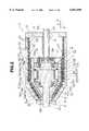
- FIG. 2is a sectional side view of a drive unit provided on the molding machine of FIG. 1;
- FIG. 3is a sectional side view of the drive unit of FIG. 2 in which a linear movement body is situated at a position different from that of FIG. 2;
- FIG. 4is a perspective view showing a front portion of the linear movement body of the molding machine of FIG. 1 and a front portion of a stationary body of the molding machine of FIG. 1 represented by an imaginary line;
- FIG. 5is a left-hand side view showing a front portion of the linear movement body of the molding machine of FIG. 1 and a front portion of the stationary body of the molding machine of FIG. 1 represented partially by an imaginary line;
- FIG. 6is a connection diagram of armature coils and field coils in a linear motor of the drive unit of the molding machine of FIG. 1;
- FIG. 7is a diagram illustrating the principle of the linear motor
- FIG. 8is a characteristic diagram showing the relationship between axial moving distance and thrust with respect to the linear motor
- FIG. 9is a sectional side view showing a portion of a drive unit according to a modified embodiment of the present invention.
- FIG. 10is a sectional side view showing a portion of a drive unit according to another modified embodiment of the present invention.
- FIG. 11is a partially sectional plan view of a drive unit according to still another modified embodiment of the present invention.
- FIG. 12is a partially sectional plan view of a drive unit according to a further modified embodiment of the present invention.
- a molding machine according to a first embodimenti.e., an in-line screw injection molding machine M, will be described with reference to FIGS. 1 to 8.
- FIG. 1shows an injection apparatus Mi of the in-line screw injection molding machine M.
- the injection apparatus Miincludes a heating cylinder 15 having an injection nozzle 16 located at the tip thereof and a hopper 17 located at a rear (right-hand side in FIG. 1) portion.
- a screw Ks(movable body K) is inserted into the heating cylinder 15 such that it can undergo rotation and reciprocating motion therein.
- a drive unit 1is provided at the rear end of the heating cylinder 15.
- An output shaft 8 of the drive unit 1is connected to the rear end of the screw Ks.
- Reference numeral 18denotes a machine base for supporting the injection apparatus Mi.
- the drive unit 1will next be described in detail with reference to FIGS. 2 to 8.
- the drive unit 1integrally includes a rotary motor R for rotating the screw Ks and a linear motor L for linearly moving the screw Ks.
- the linear motor Lfunctions as a three-phase AC servomotor and includes a linear movement body 2 supported such that it can move in axial direction Ds, and a stationary body 4 adapted to linearly move the linear movement body 2.
- the stationary body 4includes a casing 20.
- the casing 20assumes a tubular shape of square cross section, and a front (left-hand side in FIG. 1) portion thereof is reduced in size toward its front end to form a tetragonal pyramid.
- a rear cover 21is attached to the rear end face of the casing 20.
- a spindle 22projects rearward from a central portion of the rear end of the linear movement body 2 and is spline-connected to the rear cover 21 at the center thereof such that it can slide in axial direction Ds, thereby forming a rotation-restricting mechanism 9 for restricting rotation of the linear movement body 2.
- the spindle 22assumes a tubular form to allow cables 23 to run therethrough as shown in FIG. 1.
- Reference numeral 24 in FIG. 1denotes a protection cover which covers the spindle 22.
- An armature portion 25 including stationary-side magnetic-pole portions 5sa, 5sb, 5sc, . . . , 5ha, 5hb, 5hc, . . .is provided on the interior upper (upper side in FIG. 2) surface of the casing 20.
- a front portion of the interior upper surface of the casing 20forms a stationary-side inclined surface 7, and the remaining portion of the interior upper surface of the casing 20 forms a stationary-side parallel surface 26.
- the stationary-side magnetic-pole portions 5sa, 5sb, 5sc . . .are arranged on the stationary-side inclined surface 7, whereas the remaining stationary-side magnetic-pole portions 5ha, 5hb, 5hc, . . .
- An armature portion 27is also similarly configured on the interior lower (lower side in FIG. 2) surface of the casing 20.
- a configuration of the lower armature portion 27is the mirror image of the above-described configuration of the upper armature portion 25.
- FIGS. 1 to 3schematically show a number of slots 29.
- Three-phase (U phase, V phase, and W phase) armature coils 30are wound in the corresponding slots 29 formed in the armature core 28.
- the armature coils 30each include a U-phase armature coil, a V-phase armature coil, and a W-phase armature coil, each being shifted by an electrical angle of 120°.
- the first U-phase armature coilis wound from slot U1 toward slot U2: the second U-phase armature coil is wound from slot U3 toward slot U4; and the third U-phase armature coil is wound from slot U5 toward slot U6.
- the first V-phase armature coilis wound from slot V1 toward slot V2; the second V-phase armature coil is wound from slot V3 toward slot V4; and the third V-phase armature coil is wound from slot V5 toward slot V6.
- the first W-phase armature coilis wound from slot W1 toward slot W2; the second W-phase armature coil is wound from slot W3 toward slot W4; and the third W-phase armature coil is wound from slot W5 toward slot W6.
- FIG. 5shows only the stationary-side inclined surface 7, but the stationary-side parallel surface 26 and the armature portion 27 are configured similarly.
- the linear movement body 2includes a housing 35 that assumes a tubular shape of square cross section. A front portion of the housing 35 is reduced in size toward its front end to form a tetragonal pyramid. Magnetic elements 36a to 36f, 36g . . . are arranged at predetermined intervals on the outer surface of the linear movement body 2 and are magnetically isolated from each other by the housing 36 of non-magnetic material. Each of the magnetic elements 36a . . . is formed in a rectangular frame shape. Thus, a field pole portion 37 is formed on the outer upper surface of the housing 35. Moving-side magnetic-pole portions 3sa, 3sb, 3sc, . . . , 3ha, 3hb, 3hc . . .
- a front portion of the outer upper surface of the housing 35forms a moving-side inclined surface 6, and the remaining portion of the outer upper surface of the housing 35 forms a moving-side parallel surface 38.
- the moving-side inclined surface 6faces the stationary-side inclined surface 7, and the moving-side parallel surface 38 faces the stationary-side parallel surface 26.
- the moving-side magnetic-pole portions 3sa, 3sb, 3sc . . .are arranged on the moving-side inclined surface 6, whereas the remaining moving-side magnetic-pole portions 3ha, 3hb, 3hc, . . . are arranged on the moving-side parallel surface 38.
- a field pole portion 39is similarly configured on the outer lower surface of the housing 35.
- a configuration of the lower field pole portion 39is the mirror image of the above-described configuration of the upper field pole portion 37.
- a field-generating portion 41is provided on the interior left-hand surface of the casing 20.
- the field-generating portion 41is adapted to magnetize the magnetic elements 36a to 36f, 36g . . . so as to generate the moving-side magnetic-pole portions 3sa, 3sb, 3sc, . . . , 3ha, 3hb, 3hc, . . .
- a plurality of comb-shaped silicon steel platesare superposed in direction Z (FIG. 2) to form a laminated field core 42.
- a front portion of the interior surface of the field core 42forms a stationary-side inclined surface 43, and the remaining portion of the interior surface of the field core 42 forms a stationary-side parallel surface 45.
- a total of 18 slots 44are formed in the stationary-side inclined surface 43 at predetermined intervals in axial direction Ds, and many slots 44 are similarly formed in the stationary-side parallel surface 45.
- the number of slots 44is selected according to specifications of application.
- Three-phase (u phase, v phase, and w phase) field coils 46are wound in the corresponding slots 44 formed in the field core 42.
- the field coils 46each include a u-phase armature coil, a v-phase armature coil, and a w-phase armature coil, each being shifted by an electrical angle of 120°.
- the first u-phase field coilis wound from slot u1 toward slot u2; the second u-phase field coil is wound from slot u3 toward slot u4; and the third u-phase field coil is wound from slot u5 toward slot u6.
- the first v-phase field coilis wound from slot v1 toward slot v2: the second v-phase field coil is wound from slot v3 toward slot v4; and the third v-phase field coil is wound from slot V5 toward slot V6.
- the first w-phase field coilis wound from slot wl toward slot w2; the second w-phase field coil is wound from slot w3 toward slot w4; and the third w-phase field coil is wound from slot w5 toward slot w6.
- the field coils 46are wound in such a manner as to shift in electrical angle by 90°, or to shift by one slot 44 and half in position along direction X, with respect to the corresponding armature coils 30.
- the angle of shiftis not necessarily an exact electrical angle of 90°, but may be an electrical angle near 90°.
- FIG. 5shows only the stationary-side inclined surface 43, but the stationary-side parallel surface 45 is configured similarly.
- a field-generating portion 47is similarly configured on the interior right-hand surface of the casing 20.
- a configuration of the right-hand field-generating portion 47is the mirror image of the above-described configuration of the left-hand field-generating portion 41.
- the field magnetic-pole portions 37 and 39 and the field-generating portions 41 and 47serve in combination as field portions corresponding to the armature portions 25 and 27.
- the principle of operation of the linear motor Lwill next be described.
- the operation induced between the moving-side inclined surface 6 and the stationary-side inclined surface 8will be described with reference to FIGS. 4 and 5.
- the operation induced between the stationary-side parallel surface 26 and the moving-side parallel surface 38is basically similar to that induced between the inclined surfaces 6 and 7.
- alternating currents iu, iv, and iwwhich are shifted by a phase angle of 120°, flow through the field coils 46.
- imrepresents a maximum current
- a north pole for generating magnetic flux ⁇ directed toward the magnetic element 36a (36c and 36e) of the linear movement body 2is induced, and a south pole for absorbing magnetic flux ⁇ directed from the magnetic element 36b (36d and 36f) toward the field-generating portion 41 is induced.
- a relevant magnetic poleemerges in the magnetic elements 36a, 36b, 36c, 36d, . . .
- the emerging magnetic polesmove in axial direction Ds.
- the same phenomenonalso occurs in the field-generating portion 47.
- magnetic fluxis distributed in the form of a sine wave along the direction of linear movement.
- the magnetic elements 36a to 36f of the linear movement body 2are magnetized in predetermined directions according to magnetic poles (north and south poles) induced in each of the field-generating portions 41 . . .
- the moving-side magnetic-pole portions 3sa, 3sb, 3sc, . . . , 3ha, 3hb, 3hc, . . .are induced on the outer upper surface of the housing 35.
- alternating currents iu, iv, and iwcause the north pole to be induced in each of the field-generating portions 41 . . .
- the magnetic elements 36a to 36fare magnetized in the following manner.
- the south poleis induced in a surface of the magnetic element 36a (36c and 36e) opposite the corresponding field-generating portion 41 . . . and in a surface of the magnetic element 36b (36d and 36f) opposite the corresponding armature portion 25 . . .
- the north poleis induced in a surface of the magnetic element 36a (36c and 36e) opposite the corresponding armature portion 25 . . . and in a surface of the magnetic element 36b (36d and 36f) opposite the corresponding field-generating portion 41 . . .
- magnetic flux ⁇(dotted line) induced from the north-pole region of the field-generating portion 41 passes through the south-pole surface (side surface) of the magnetic element 36a and reaches the interior thereof.
- the magnetic flux ⁇ which has reached the interior of the magnetic element 36apasses through the north-pole surface (upper surface) of the magnetic element 36a and reaches the interior of the armature portion 25.
- the magnetic flux ⁇passes through the interior of the armature portion 25 an axial direction Ds and passes through the south-pole surface (upper surface) of the magnetic element 36b, thus reaching the interior of the magnetic element 36b.
- FIG. 4only shows the relationship between the left-hand field-generating portion 41 and the upper armature portion 25. The same relationship is established between the right-hand field-generating portion 47 and the lower armature portion 27.
- a predetermined closed magnetic circuitis formed by means of the field portions (field-generating portions 41 and 47 and magnetic elements 36a . . . and the armature portions 25 and 27.
- armature currentsThree-phase alternating currents (armature currents) IU, IV, and IW, which are shifted by a phase angle of 120°, flow through the armature coils 30 of each of the armature portions 25 . . .
- Imrepresents a maximum current
- the magnitude of torque Tcan be controlled simply by controlling the magnitude of current flowing through the field coils 46 and the armature coils 30.
- armature currentalso induces magnetic flux.
- the housing 35 of the linear movement body 2is non-magnetic, the linear movement body 2 is less likely to be magnetized; i.e., the linear movement body 2 is less affected by the magnetic flux.
- FIG. 6shows how the armature coils 30 and the field coils 46 are connected.
- the armature coils 30 and the field coils 46can be series-wound.
- the drive unit 1therefore, can be controlled as a series-wound AC motor by a single inverter.
- the field coils 46are provided with additional coils for controlling thrust.
- a desired thrustcan be generated.
- separate invertersmay be provided and may perform control so as to establish a phase difference of 90° between field current and armature current.
- the moving-side inclined surface 6is formed at the front portion of the linear movement body 2, and the moving-side magnetic-pole portions 3sa, 3sb, 3sc . . . are arranged on the moving-side inclined surface 6.
- the stationary-side inclined surface 7is formed at the front portion of the stationary body 4 and faces the moving-side inclined surface 6.
- the stationary-side magnetic-pole portions 5sa, 5sb, 5sc . . .are arranged on the stationary-side inclined surface 7.
- attractive force Fis generated between the linear movement body 2 (moving-side magnetic-pole portions 3sa, 3sb, 3sc, . . .
- Attractive force Fcauses generation, on the linear movement body 2, of thrust Fx greater than torque T generated according to Fleming's rule.
- the linear movement body 2 and the stationary body 4may be arranged so as to face vertical surface-to-vertical surface with respect to axial direction Ds. In this case, however, moving distance X of the linear movement body 2 becomes too short to be practical. Also, control of thrust Fx becomes very difficult.
- moving distance X of the linear movement body 2is greater than gap d between the moving-side inclined surface 6 and the stationary-side inclined surface 7 (i.e., X>d).
- FIG. 8is a characteristic diagram showing the relationship between moving distance X and thrust Fx among the following cases: the linear movement body 2 and the stationary body 4 is arranged so as to face vertical surface-to-vertical surface with respect to axial direction Ds; the inclined surfaces 6 and 7 face each other as in the case of the linear motor L according to the present embodiment; and parallel surfaces are simply provided as in the case of a conventional linear motor.
- thrust Fxdecreases abruptly with moving distance X.
- thrust Fxis constant irrespective of moving distance X.
- hollow space Sris present within the linear movement portion 2, i.e., within the housing 35.
- the rotary motor Ris disposed within the hollow space Sr.
- the rotary motor Rincludes a shaft 51 disposed at the center thereof.
- a rotor portion (magnet rotor) 52is provided at an intermediate portion of the shaft 51.
- a front portion of the shaft 51is formed into the output shaft 8.
- the front end of the output shaft 8projects forward through a front end opening formed in the housing 35 and is connected to the rear end of screw Ks.
- the front part of the rotor portion 52is formed into a supported portion 53, and the rear part of the rotor portion 52 is formed into a supported portion 54.
- the supported portions 53 and 54are rotatably supported within the housing 35 via bearing mechanisms 55 and 56, respectively.
- the bearing mechanisms 55 and 56include thrust bearings 55s and 56s, respectively.
- the thrust bearings 55s and 56sconstitute a pressure endurance mechanism 10 for bearing a pressure that is imposed on the output shaft 8 in axial direction Ds.
- a stator portion 57is disposed on the interior surface of the housing 35 in such a manner as to face the rotor portion 52.
- the stator portion 57 and the rotor portion 52constitute a three-phase AC servomotor.
- the stator portion 57includes a plurality of core portions 57s, which are arranged at predetermined pitches along the interior surface of the housing 35, and stator coils 57c wound on the corresponding core portions 57s.
- the rotor portion 52includes a plurality of magnets 52m circumferentially arranged thereon.
- a rotary encoder 58 for detecting the rotational position (rotational speed) of the shaft 51is attached to the rear end of the supported portion 54. Cables connected to the stator coils 57c and the rotary encoder 58 are included in the cables 23 and are thus led out to the exterior of the drive unit 1 through the hollow spindle 22.
- the cables 23are connected to a controller 19 shown in FIG. 1.
- the armature coils 30 and the field coils 46 of the linear motor Lare connected to the controller 19.
- Reference numeral 19s in FIG. 1denotes a setting unit connected to the controller 19.
- various sensorssuch as a position sensor for detecting position of the screw Ks, a pressure sensor for detecting pressure imposed on the screw Ks, and a speed sensor for detecting an advancing speed of the screw Ks.
- FIG. 3shows a state in which the linear movement body 2 is retreated.
- the linear motor Lis driven so as to linearly move the linear movement body 2, thereby advancing the screw Ks via the output shaft 8.
- the advancing screw Kscauses the measured, molten resin to be injected and charged into an unillustrated mold through the injection nozzle 16.
- the moving-side magnetic-pole portions 3ha . . . disposed on the moving-side parallel surfaces 38 of the linear movement body 2 and the stationary-side magnetic-pole portions 5ha . . . disposed on the stationary-side parallel surfaces 26 of the stationary body 4operate dominantly, causing the linear movement body 2 to advance.
- the controller 19performs feedback control over the screw Ks with respect to speed, on the basis of a target screw speed (injection rate) set in the setting unit 19s and a detected speed of the screw Ks obtained from an unillustrated speed sensor.
- the moving-side magnetic-pole portions 3sa . . . on the moving-side inclined surfaces 6 and the stationary-side magnetic-pole portions 5sa . . . on the stationary-side inclined surfaces 7operate dominantly, so that a thrust Fx is generated.
- the controller 19performs feedback control over the screw Ks with respect to pressure, on the basis of a target holding pressure set in the setting unit 19s and a detected pressure of the screw Ks obtained from an unillustrated pressure sensor. Accordingly, during pressure holding, the generated thrust Fx secures a large holding pressure.
- a holding pressureis directly applied to the rotary motor R and is borne by the thrust bearings 55s and 56s of the pressure endurance mechanism 10.
- FIG. 9shows a modified embodiment of the pressure endurance mechanism 10 of the rotary motor R.
- the thrust bearings 55s and 56s of the rotary motor R shown in FIG. 2bear pressure which is applied to the output shaft 8 in axial direction Ds.
- the shaft 51is accommodated within the housing 35 such that a stopper portion 61 formed within the housing 35 allows the shaft 51 to move by a predetermined distance in an axial direction Ds.
- a contact plate 62is integrally provided on a portion of the shaft 51.
- An engagement portion 63is integrally provided on the interior surface of the housing 35 and is located behind the contact plate 62.
- An electromagnet portion 64is integrally provided within the housing 35 and is located ahead of the contact plate 62.
- the contact plate 62, the engagement portion 63, and the electromagnet portion 64constitute the pressure endurance mechanism 10.
- an injection steppressure (such as holding pressure) is applied backward to the screw Ks.
- pressuresuch as holding pressure
- the contact plate 62abuts the engagement portion 63, so that backward movement of the shaft 51 is restricted.
- a force of about 20 tonscan be endured.
- the electromagnet portion 64is excited to thereby attract the contact plate 62 forward such that a gap of about 0.3 mm to 0.5 mm is formed between the contact plate 62 and the electromagnet portion 64, while movement of a radial bearing 65 is restricted by the stopper portion 61 formed within the housing 35.
- FIG. 10shows another modified embodiment of the pressure endurance mechanism 10, which assumes the form of a magnetic bearing and is configured in the following manner.
- Front and rear parts of the rotor portion 52are formed into inclined portions (e.g., tapered portions) 71f and 71r, respectively.
- Magnetic attraction elements 72f and 72rformed from silicon steel plates are disposed on the inclined portions 71f and 71r, respectively.
- Inclined portions 73f and 73rare formed on the interior surface of the housing 35 in such a manner as to face the inclined portions 71f and 71r, respectively.
- Multipolar electromagnets 74f and 74rare disposed on the inclined portions 73f and 73r, respectively.
- FIG. 10the same features as those of FIG. 2 are denoted by common reference numerals for clarification, and detailed description thereof is omitted.
- FIG. 11shows a modified embodiment of the rotation-restricting mechanism 9 interposed between the linear movement body 2 and the stationary body 4 and adapted to restrict rotation of the linear movement body 2.
- tie bars 83a and 83bextend between a tie bar support 81 attached to the heating cylinder 15 and a tie bar support 82 attached to the casing 20.
- a slider 84is slidably mounted on the tie bars 83a and 83b.
- a tip portion of the output shaft 8 of the drive unit 1is attached to the slider 84 in such a manner as to be rotatable via bearings 85a, 85b, 85c, and 85d disposed on the outer circumferential surface thereof.
- a pressure sensor 86such as a load cell, is interposed between the tip portion of the output shaft 8 and the slider 84.
- the tip end face of the output shaft 8is connected to the rear end of the screw Ks.
- the tip of the housing 35extends forward and is connected to the rear end face of the slider 84.
- the pressure sensor 86detects pressure applied to the screw Ks in axial direction Ds.
- FIG. 11the same features as those of FIGS. 1 and 2 are denoted by common reference numerals for clarification, and detailed description thereof is omitted.
- FIG. 12shows a further modified embodiment of the present invention in which the rotary motor R is disposed outside the linear movement body 2 and is integrally connected to the linear movement body 2.
- the housing 35is integrally attached to the rear end face of the slider 84, while the front end of the linear movement body 2 is connected to the rear end of the housing 35.
- the rotary motor Ris disposed within the housing 35.
- the output shaft 8(shaft 51) projects forward through a front end opening of the housing 35.
- a tip portion of the output shaft 8is attached to the slider 84 in such a manner as to be rotatable via the bearings 85a, 85b, 85c, and 85d disposed on the outer circumferential surface thereof.
- FIG. 12the same features as those of FIGS. 2 and 11 are denoted by common reference numerals for clarification, and detailed description thereof is omitted.
- the linear motor L of FIG. 2is described while mentioning two pairs of armature cores 28 and two pairs of field cores 42 provide around the linear movement body 2.
- the number of armature cores 28 and the number of field cores 42are not particularly limited.
- two field cores 42may be combined with a single armature core 28; a single field core 42 may be combined with two armature cores 28; and three or more armature cores 28 may be combined with three or more field cores 42.
- the configuration of the rotation-restricting mechanism 9, the pressure endurance mechanism 10, or the rotary motor Ris not particularly limited, but may be modified in various ways.
- the above embodimentsare described while mentioning the inclined surfaces 6 and 7 formed at a front portion of the linear motor L.
- the inclined surfaces 6 and 7may be formed at a rear or intermediate portion of the linear motor L.
- the configuration of the linear motor L and that of the rotary motor Rare not particularly limited, but may be modified in various ways.
- the linear motor L and the rotary motor Rare described while mentioning the linear movement boy 2 of square cross section and the stationary body 4 of square cross section.
- the linear movement body 2 and the stationary body 4may assume a polygonal or circular section.
- the armature portions 25 . . . and the field-generating portions 41 . . .each assume quadrantal section.
- the magnetic elements 36a . . . disposed on the linear movement body 2may be replaced by magnets.
- the field-generating portions of the embodiment shown in FIG. 5become unnecessary, so that the armature portions 25 . . . can be formed on all of the upper, lower, left-hand, and right-hand sides of the casing 20.
- a plurality of drive units 1may be connected together while sharing the same shaft 51. Torque (pressure) increases with the number of the drive units 1 connected. By selecting an angle of inclination of the inclined surfaces 6 and 7, the magnitude (rate of change) of thrust Fx with respect to moving distance X of the movable body K can be modified accordingly.
- the terms "moving-side" and "stationary-side”refer to a relative concept.
- a "moving-side” elementmay be stationary, and a “stationary-side” element may be movable.
- the output shaftmay be connected to the stationary body.
- the injection molding machine Mis described while mentioning the screw Ks disposed within the injection apparatus Mi and serving as the movable body K.
- the movable body Kis not particularly limited, but may assume various forms that rotate and move linearly, such as a screw disposed within a heating cylinder of a plasticizing apparatus of a preplasticization injection molding machine, wherein a valve portion for opening and closing a resin passage of the heating cylinder is provided at the tip end of the screw, or a mold exchange rotary table for supporting a plurality of molds.
Landscapes
- Engineering & Computer Science (AREA)
- Power Engineering (AREA)
- Manufacturing & Machinery (AREA)
- Mechanical Engineering (AREA)
- Physics & Mathematics (AREA)
- Chemical & Material Sciences (AREA)
- Combustion & Propulsion (AREA)
- Electromagnetism (AREA)
- Injection Moulding Of Plastics Or The Like (AREA)
- Linear Motors (AREA)
Abstract
Description
Claims (13)
Applications Claiming Priority (2)
| Application Number | Priority Date | Filing Date | Title |
|---|---|---|---|
| JP12222998AJP3427171B2 (en) | 1998-05-01 | 1998-05-01 | Molding machine |
| JP10-122229 | 1998-05-01 |
Publications (1)
| Publication Number | Publication Date |
|---|---|
| US6051896Atrue US6051896A (en) | 2000-04-18 |
Family
ID=14830774
Family Applications (1)
| Application Number | Title | Priority Date | Filing Date |
|---|---|---|---|
| US09/300,510Expired - Fee RelatedUS6051896A (en) | 1998-05-01 | 1999-04-28 | Molding machine |
Country Status (2)
| Country | Link |
|---|---|
| US (1) | US6051896A (en) |
| JP (1) | JP3427171B2 (en) |
Cited By (35)
| Publication number | Priority date | Publication date | Assignee | Title |
|---|---|---|---|---|
| WO2000067984A1 (en)* | 1999-05-05 | 2000-11-16 | Karl Hehl | Injection molding machine for processing plastics |
| US6236124B1 (en)* | 1998-05-01 | 2001-05-22 | Nisso Electric Corporation | Linear motor |
| WO2002045939A1 (en)* | 2000-12-04 | 2002-06-13 | Mannesmann Plastics Machinery Gmbh | Injection unit for an injection moulding machine |
| US20030054059A1 (en)* | 2001-09-14 | 2003-03-20 | Sumitomo Heavy Industries, Ltd. | Injection apparatus |
| US20030068396A1 (en)* | 2001-10-05 | 2003-04-10 | Toyo Machinery & Metal Co., Ltd. | Injection molding machine |
| US20030193247A1 (en)* | 2002-04-12 | 2003-10-16 | Gilles Delaire | Actuator having a permanent magnet |
| US20040026809A1 (en)* | 2001-08-17 | 2004-02-12 | Shunshi Kuzumi | Injection device and injection method |
| US20040071810A1 (en)* | 2002-10-09 | 2004-04-15 | Chia-Chun Hsu | Electromagnetic coaxial driving injection apparatus |
| US6793477B2 (en)* | 2000-04-24 | 2004-09-21 | Fanuc Ltd. | Injection mechanism of injection molding machine |
| US20040232791A1 (en)* | 2003-05-19 | 2004-11-25 | Luc Gilbert | System for driving a rotatable machine |
| WO2005122366A1 (en)* | 2004-06-11 | 2005-12-22 | Siemens Aktiengesellschaft | Drive device |
| WO2006032629A1 (en)* | 2004-09-20 | 2006-03-30 | Siemens Aktiengesellschaft | Electric machine |
| US20060147578A1 (en)* | 2003-03-04 | 2006-07-06 | Sumitomo Heavy Industries, Ltd. | Injection molding machine driving device, injection device, and mold clamping device |
| EP1696541A1 (en)* | 2005-02-24 | 2006-08-30 | Ortlinghaus-Werke GmbH | Non rotating linear actuator |
| WO2007057313A1 (en)* | 2005-11-18 | 2007-05-24 | Siemens Aktiengesellschaft | Plastics injection-moulding machine with integrated, linear-rotary direct drive |
| WO2007090710A1 (en)* | 2006-02-09 | 2007-08-16 | Siemens Aktiengesellschaft | Motor with rotational and linear drive with integrated axial force measurement |
| US20070237658A1 (en)* | 2006-04-06 | 2007-10-11 | Micropump, Inc., A Unit Of Idex Corporation | Magnetically driven valveless piston pumps |
| US20070296121A1 (en)* | 2006-06-07 | 2007-12-27 | Husky Injection Molding Systems Ltd. | Molding-system drive |
| US20090017152A1 (en)* | 2004-12-20 | 2009-01-15 | Toyo Machinery & Metal Co., Ltd. | Method for controlling measurement in injection molding machine, and injection molding machine |
| WO2009033926A1 (en)* | 2007-09-07 | 2009-03-19 | Siemens Aktiengesellschaft | Method for operating an injection device for an injection moulding machine, an injection device and an injection moulding machine with such an injection device |
| US20090087505A1 (en)* | 2007-10-01 | 2009-04-02 | Siemens Aktiengesellschaft | Injection molding machine |
| US20090251013A1 (en)* | 2004-12-15 | 2009-10-08 | Siemens Aktiengesellschaft | Electric Motor for Rotation and Axial Movement |
| US20090297655A1 (en)* | 2004-11-22 | 2009-12-03 | Siemens Aktiengesellschaft | Linearly Displaceable Rotary Drive For A Plastic Injection-Molding Machine |
| US20110206797A1 (en)* | 2007-08-07 | 2011-08-25 | Toyo Machinery & Metal Co., Ltd. | Molding Machine |
| US20110224616A1 (en)* | 2008-05-20 | 2011-09-15 | Avant Medical Corporation | Autoinjector system |
| CN104539122A (en)* | 2014-12-08 | 2015-04-22 | 沈阳工业大学 | Rotary linear permanent magnet electric motor |
| US9616173B2 (en) | 2008-07-23 | 2017-04-11 | Avant Medical Corporation | System and method for an injection using a syringe needle |
| US9925336B2 (en) | 2008-05-20 | 2018-03-27 | Avant Medical Corp. | Cassette for a hidden injection needle |
| USD829890S1 (en) | 2012-04-20 | 2018-10-02 | Amgen Inc. | Injection device |
| US10092703B2 (en) | 2013-03-15 | 2018-10-09 | Amgen Inc. | Drug cassette, autoinjector, and autoinjector system |
| US10092706B2 (en) | 2011-04-20 | 2018-10-09 | Amgen Inc. | Autoinjector apparatus |
| US10492990B2 (en) | 2013-03-15 | 2019-12-03 | Amgen Inc. | Drug cassette, autoinjector, and autoinjector system |
| DE102017117003B4 (en) | 2016-07-28 | 2019-12-05 | Engel Austria Gmbh | Storage container for a molding machine |
| USD898908S1 (en) | 2012-04-20 | 2020-10-13 | Amgen Inc. | Pharmaceutical product cassette for an injection device |
| US10892078B2 (en) | 2016-12-07 | 2021-01-12 | Mts Systems Corporation | Electric actuator |
Families Citing this family (1)
| Publication number | Priority date | Publication date | Assignee | Title |
|---|---|---|---|---|
| JP4717774B2 (en)* | 2006-10-13 | 2011-07-06 | 日精樹脂工業株式会社 | Injection molding machine |
Citations (14)
| Publication number | Priority date | Publication date | Assignee | Title |
|---|---|---|---|---|
| US4133460A (en)* | 1976-01-29 | 1979-01-09 | Jerpbak Jeffery P | Apparatus embodying explosively removable sleeve |
| US4152570A (en)* | 1976-10-25 | 1979-05-01 | Inoue-Japax Research Inc. | Drive assembly for multi-directional lateral displacement between tool and workpiece |
| US4242606A (en)* | 1978-03-08 | 1980-12-30 | Robert Bosch Gmbh | Magnetic final control element for a regulator apparatus |
| US4511319A (en)* | 1981-08-24 | 1985-04-16 | Ube Industries, Inc. | Vent-type plastication molding machine |
| US4565116A (en)* | 1982-10-14 | 1986-01-21 | Karl Hehl | Hydraulic speed controls for die closing unit of injection molding machine |
| US4669013A (en)* | 1985-04-02 | 1987-05-26 | International Business Machines Corporation | Multiple coils for reduction of stray magnetic fields in disk file actuators |
| US5443587A (en)* | 1992-06-09 | 1995-08-22 | Nissei Plastic Industrial Co., Ltd. | Injection molding machine control having motor slip compensator |
| US5470592A (en)* | 1993-10-27 | 1995-11-28 | Ferromatik Milacron Maschinenbau Gmbh | Apparatus for generating clamping force in injection molding machines |
| US5472657A (en)* | 1991-08-26 | 1995-12-05 | Fuji Photo Film Co., Ltd. | Method for molding plastic shutter for magnetic disk cartridge |
| JPH0911290A (en)* | 1995-06-30 | 1997-01-14 | Nissei Plastics Ind Co | Method and device for controlling injection molding machine |
| US5661446A (en)* | 1995-06-07 | 1997-08-26 | Mts Systems Corporation | Electromagnetic actuator |
| US5792396A (en)* | 1995-10-20 | 1998-08-11 | Nissei Plastic Industrial Co. Ltd. | Position detecting system for an injection molding apparatus |
| US5868978A (en)* | 1996-11-21 | 1999-02-09 | Matsushita Electric Industrial Co., Ltd. | Injection molding method for thin components |
| US5897815A (en)* | 1993-05-24 | 1999-04-27 | Impac Technologies | Process for injection molding of slurries |
- 1998
- 1998-05-01JPJP12222998Apatent/JP3427171B2/ennot_activeExpired - Fee Related
- 1999
- 1999-04-28USUS09/300,510patent/US6051896A/ennot_activeExpired - Fee Related
Patent Citations (14)
| Publication number | Priority date | Publication date | Assignee | Title |
|---|---|---|---|---|
| US4133460A (en)* | 1976-01-29 | 1979-01-09 | Jerpbak Jeffery P | Apparatus embodying explosively removable sleeve |
| US4152570A (en)* | 1976-10-25 | 1979-05-01 | Inoue-Japax Research Inc. | Drive assembly for multi-directional lateral displacement between tool and workpiece |
| US4242606A (en)* | 1978-03-08 | 1980-12-30 | Robert Bosch Gmbh | Magnetic final control element for a regulator apparatus |
| US4511319A (en)* | 1981-08-24 | 1985-04-16 | Ube Industries, Inc. | Vent-type plastication molding machine |
| US4565116A (en)* | 1982-10-14 | 1986-01-21 | Karl Hehl | Hydraulic speed controls for die closing unit of injection molding machine |
| US4669013A (en)* | 1985-04-02 | 1987-05-26 | International Business Machines Corporation | Multiple coils for reduction of stray magnetic fields in disk file actuators |
| US5472657A (en)* | 1991-08-26 | 1995-12-05 | Fuji Photo Film Co., Ltd. | Method for molding plastic shutter for magnetic disk cartridge |
| US5443587A (en)* | 1992-06-09 | 1995-08-22 | Nissei Plastic Industrial Co., Ltd. | Injection molding machine control having motor slip compensator |
| US5897815A (en)* | 1993-05-24 | 1999-04-27 | Impac Technologies | Process for injection molding of slurries |
| US5470592A (en)* | 1993-10-27 | 1995-11-28 | Ferromatik Milacron Maschinenbau Gmbh | Apparatus for generating clamping force in injection molding machines |
| US5661446A (en)* | 1995-06-07 | 1997-08-26 | Mts Systems Corporation | Electromagnetic actuator |
| JPH0911290A (en)* | 1995-06-30 | 1997-01-14 | Nissei Plastics Ind Co | Method and device for controlling injection molding machine |
| US5792396A (en)* | 1995-10-20 | 1998-08-11 | Nissei Plastic Industrial Co. Ltd. | Position detecting system for an injection molding apparatus |
| US5868978A (en)* | 1996-11-21 | 1999-02-09 | Matsushita Electric Industrial Co., Ltd. | Injection molding method for thin components |
Cited By (88)
| Publication number | Priority date | Publication date | Assignee | Title |
|---|---|---|---|---|
| US6236124B1 (en)* | 1998-05-01 | 2001-05-22 | Nisso Electric Corporation | Linear motor |
| US6769892B1 (en) | 1999-05-05 | 2004-08-03 | Karl Hehl | Injection molding machine for processing plastics |
| WO2000067984A1 (en)* | 1999-05-05 | 2000-11-16 | Karl Hehl | Injection molding machine for processing plastics |
| US6793477B2 (en)* | 2000-04-24 | 2004-09-21 | Fanuc Ltd. | Injection mechanism of injection molding machine |
| WO2002045939A1 (en)* | 2000-12-04 | 2002-06-13 | Mannesmann Plastics Machinery Gmbh | Injection unit for an injection moulding machine |
| US7033158B2 (en)* | 2000-12-04 | 2006-04-25 | Mannesmann Plastics Machinery Gmbh | Injection unit for an injection moulding machine |
| US20040018270A1 (en)* | 2000-12-04 | 2004-01-29 | Klaus Becker | Injection unit for an injection moulding machine |
| EP1418037A4 (en)* | 2001-08-17 | 2009-06-03 | Sumitomo Heavy Industries | Injection device and injection method |
| US20040026809A1 (en)* | 2001-08-17 | 2004-02-12 | Shunshi Kuzumi | Injection device and injection method |
| US6755636B2 (en) | 2001-09-14 | 2004-06-29 | Sumitomo Heavy Industries, Ltd. | Injection apparatus |
| US7329373B2 (en) | 2001-09-14 | 2008-02-12 | Sumitomo Heavy Industries, Ltd. | Control method of rotational speed of screw for injection molding machine |
| US20040185130A1 (en)* | 2001-09-14 | 2004-09-23 | Sumitomo Heavy Industries, Ltd. | Injection molding apparatus |
| US20040188877A1 (en)* | 2001-09-14 | 2004-09-30 | Sumitomo Heavy Industries, Ltd. | Control method of rotational speed of screw for injection molding machine |
| US7125233B2 (en) | 2001-09-14 | 2006-10-24 | Sumitomo Heavy Industries, Ltd. | Injection molding apparatus |
| EP1319489A3 (en)* | 2001-09-14 | 2003-08-06 | Sumitomo Heavy Industries, Ltd. | Electric injection moulding machine |
| US20030054059A1 (en)* | 2001-09-14 | 2003-03-20 | Sumitomo Heavy Industries, Ltd. | Injection apparatus |
| US7128550B2 (en)* | 2001-10-05 | 2006-10-31 | Toyo Machinery & Metal Co., Ltd. | Injection molding machine |
| US20030068396A1 (en)* | 2001-10-05 | 2003-04-10 | Toyo Machinery & Metal Co., Ltd. | Injection molding machine |
| US6787946B2 (en)* | 2002-04-12 | 2004-09-07 | Siemens Vdo Automotive Inc. | Actuator having a permanent magnet |
| US20030193247A1 (en)* | 2002-04-12 | 2003-10-16 | Gilles Delaire | Actuator having a permanent magnet |
| US20040263002A1 (en)* | 2002-04-12 | 2004-12-30 | Siemens Vdo Automotive Inc. | Actuator having a permanent magnet |
| US6867512B2 (en)* | 2002-04-12 | 2005-03-15 | Siemens Vdo Automotive Inc. | Actuator having a permanent magnet |
| US7090477B2 (en)* | 2002-10-09 | 2006-08-15 | Industrial Technology Research Institute | Electromagnetic coaxial driving injection apparatus |
| US20040071810A1 (en)* | 2002-10-09 | 2004-04-15 | Chia-Chun Hsu | Electromagnetic coaxial driving injection apparatus |
| US20060147578A1 (en)* | 2003-03-04 | 2006-07-06 | Sumitomo Heavy Industries, Ltd. | Injection molding machine driving device, injection device, and mold clamping device |
| EP1607205A4 (en)* | 2003-03-04 | 2007-05-23 | Sumitomo Heavy Industries | Injection molding machine driving device, injection device and mold clamping device |
| US7442022B2 (en) | 2003-03-04 | 2008-10-28 | Sumitomo Heavy Industries, Ltd. | Drive apparatus for injection molding machine, injection apparatus, and mold clamping apparatus |
| US7041044B2 (en)* | 2003-05-19 | 2006-05-09 | Andritz-Guinard S.A.S. | Rotatable machine or centrifuge with driving motors in a simple casing |
| US20040232791A1 (en)* | 2003-05-19 | 2004-11-25 | Luc Gilbert | System for driving a rotatable machine |
| WO2005122366A1 (en)* | 2004-06-11 | 2005-12-22 | Siemens Aktiengesellschaft | Drive device |
| US7841250B2 (en) | 2004-06-11 | 2010-11-30 | Siemens Aktiengesellschaft | Drive device |
| CN1934770B (en)* | 2004-06-11 | 2010-05-26 | 西门子公司 | drive unit |
| US20080127757A1 (en)* | 2004-06-11 | 2008-06-05 | Suemens Aktiengesellschaft | Drive Device |
| WO2006032629A1 (en)* | 2004-09-20 | 2006-03-30 | Siemens Aktiengesellschaft | Electric machine |
| US20080309179A1 (en)* | 2004-09-20 | 2008-12-18 | Siemens Aktiengesellschaft | Electric Machine |
| US20090297655A1 (en)* | 2004-11-22 | 2009-12-03 | Siemens Aktiengesellschaft | Linearly Displaceable Rotary Drive For A Plastic Injection-Molding Machine |
| US7819655B2 (en)* | 2004-11-22 | 2010-10-26 | Siemens Aktiengesellschaft | Linearly displaceable rotary drive for a plastic injection-molding machine |
| US20090251013A1 (en)* | 2004-12-15 | 2009-10-08 | Siemens Aktiengesellschaft | Electric Motor for Rotation and Axial Movement |
| US7677875B2 (en)* | 2004-12-20 | 2010-03-16 | Toyo Machinery & Metal Co., Ltd. | Injection molding machine for controlling measurement of an in-line screw |
| US20090017152A1 (en)* | 2004-12-20 | 2009-01-15 | Toyo Machinery & Metal Co., Ltd. | Method for controlling measurement in injection molding machine, and injection molding machine |
| EP1696541A1 (en)* | 2005-02-24 | 2006-08-30 | Ortlinghaus-Werke GmbH | Non rotating linear actuator |
| DE102005055491B4 (en)* | 2005-11-18 | 2009-09-10 | Siemens Ag | Drive for a plastic injection molding machine |
| WO2007057313A1 (en)* | 2005-11-18 | 2007-05-24 | Siemens Aktiengesellschaft | Plastics injection-moulding machine with integrated, linear-rotary direct drive |
| CN101312814B (en)* | 2005-11-18 | 2012-06-13 | 西门子公司 | Plastic injection molding machine with built-in linear-rotary direct drive |
| US8022580B2 (en)* | 2005-11-18 | 2011-09-20 | Siemens Aktiengesellschaft | Plastics injection-molding machine with integrated, linear-rotary direct drive |
| US20080284256A1 (en)* | 2005-11-18 | 2008-11-20 | Siemens Aktiengesellschaft | Plastics Injection-Molding Machine With Integrated, Linear-Rotary Direct Drive |
| DE102005055491A1 (en)* | 2005-11-18 | 2007-05-24 | Siemens Ag | Plastic injection molding machine with integrated, linear-rotary direct drive |
| US20090007698A1 (en)* | 2006-02-09 | 2009-01-08 | Siemens Aktiengesellschaft | Motor with rotational and linear drive with integrated axial force measurement |
| WO2007090710A1 (en)* | 2006-02-09 | 2007-08-16 | Siemens Aktiengesellschaft | Motor with rotational and linear drive with integrated axial force measurement |
| US7793558B2 (en) | 2006-02-09 | 2010-09-14 | Siemens Aktiengesellschaft | Motor with rotational and linear drive with integrated axial force measurement |
| US20070237658A1 (en)* | 2006-04-06 | 2007-10-11 | Micropump, Inc., A Unit Of Idex Corporation | Magnetically driven valveless piston pumps |
| US7798783B2 (en)* | 2006-04-06 | 2010-09-21 | Micropump, Inc. | Magnetically driven valveless piston pumps |
| US20070296121A1 (en)* | 2006-06-07 | 2007-12-27 | Husky Injection Molding Systems Ltd. | Molding-system drive |
| US8128391B2 (en)* | 2007-08-07 | 2012-03-06 | Toyo Machinery & Metal Co., Ltd. | Molding machine |
| US20110206797A1 (en)* | 2007-08-07 | 2011-08-25 | Toyo Machinery & Metal Co., Ltd. | Molding Machine |
| WO2009033926A1 (en)* | 2007-09-07 | 2009-03-19 | Siemens Aktiengesellschaft | Method for operating an injection device for an injection moulding machine, an injection device and an injection moulding machine with such an injection device |
| CN101402238A (en)* | 2007-10-01 | 2009-04-08 | 西门子公司 | Injection moulding machine |
| CN101402238B (en)* | 2007-10-01 | 2014-01-22 | 西门子公司 | Injection moulding machine |
| US20090087505A1 (en)* | 2007-10-01 | 2009-04-02 | Siemens Aktiengesellschaft | Injection molding machine |
| US7878784B2 (en)* | 2007-10-01 | 2011-02-01 | Siemens Aktiengesellschaft | Injection molding machine |
| US20110224616A1 (en)* | 2008-05-20 | 2011-09-15 | Avant Medical Corporation | Autoinjector system |
| US10864324B2 (en) | 2008-05-20 | 2020-12-15 | Avant Medical Corp. | Autoinjector system |
| US20120101439A9 (en)* | 2008-05-20 | 2012-04-26 | Avant Medical Corporation | Autoinjector system |
| US11883633B2 (en) | 2008-05-20 | 2024-01-30 | Avant Medical Corp. | Autoinjector system |
| US10792426B2 (en) | 2008-05-20 | 2020-10-06 | Avant Medical Corp. | Autoinjector system |
| US9925336B2 (en) | 2008-05-20 | 2018-03-27 | Avant Medical Corp. | Cassette for a hidden injection needle |
| US9974904B2 (en)* | 2008-05-20 | 2018-05-22 | Avant Medical Corp. | Autoinjector system |
| US12186535B2 (en) | 2008-07-23 | 2025-01-07 | Avant Medical Corp. | System and method for an injection using a syringe needle |
| US11724032B2 (en) | 2008-07-23 | 2023-08-15 | Avant Medical Corp. | System and method for an injection using a syringe needle |
| US10639422B2 (en) | 2008-07-23 | 2020-05-05 | Avant Medical Corp. | System and method for an injection using a syringe needle |
| US9616173B2 (en) | 2008-07-23 | 2017-04-11 | Avant Medical Corporation | System and method for an injection using a syringe needle |
| US11986643B2 (en) | 2011-04-20 | 2024-05-21 | Amgen Inc. | Autoinjector apparatus |
| US10092706B2 (en) | 2011-04-20 | 2018-10-09 | Amgen Inc. | Autoinjector apparatus |
| US11419990B2 (en) | 2011-04-20 | 2022-08-23 | Amgen Inc. | Autoinjector apparatus |
| US10918805B2 (en) | 2011-04-20 | 2021-02-16 | Amgen Inc. | Autoinjector apparatus |
| US12350480B2 (en) | 2011-04-20 | 2025-07-08 | Amgen Inc. | Autoinjector apparatus |
| USD898908S1 (en) | 2012-04-20 | 2020-10-13 | Amgen Inc. | Pharmaceutical product cassette for an injection device |
| USD829890S1 (en) | 2012-04-20 | 2018-10-02 | Amgen Inc. | Injection device |
| USD1076075S1 (en) | 2012-04-20 | 2025-05-20 | Amgen Inc. | Pharmaceutical product cassette for an injection device |
| US10786629B2 (en) | 2013-03-15 | 2020-09-29 | Amgen Inc. | Drug cassette, autoinjector, and autoinjector system |
| US11020537B2 (en) | 2013-03-15 | 2021-06-01 | Amgen Inc. | Drug cassette, autoinjector, and autoinjector system |
| US10492990B2 (en) | 2013-03-15 | 2019-12-03 | Amgen Inc. | Drug cassette, autoinjector, and autoinjector system |
| US10092703B2 (en) | 2013-03-15 | 2018-10-09 | Amgen Inc. | Drug cassette, autoinjector, and autoinjector system |
| US11944798B2 (en) | 2013-03-15 | 2024-04-02 | Amgen Inc. | Drug cassette, autoinjector, and autoinjector system |
| CN104539122B (en)* | 2014-12-08 | 2017-04-12 | 沈阳工业大学 | Rotary linear permanent magnet electric motor |
| CN104539122A (en)* | 2014-12-08 | 2015-04-22 | 沈阳工业大学 | Rotary linear permanent magnet electric motor |
| DE102017117003B4 (en) | 2016-07-28 | 2019-12-05 | Engel Austria Gmbh | Storage container for a molding machine |
| US10892078B2 (en) | 2016-12-07 | 2021-01-12 | Mts Systems Corporation | Electric actuator |
Also Published As
| Publication number | Publication date |
|---|---|
| JP3427171B2 (en) | 2003-07-14 |
| JPH11309752A (en) | 1999-11-09 |
Similar Documents
| Publication | Publication Date | Title |
|---|---|---|
| US6051896A (en) | Molding machine | |
| US6247913B1 (en) | Molding machine | |
| US6639337B1 (en) | Motor/generator with multiple rotors | |
| US8143750B2 (en) | Linear motor having coils surrounding an axially moving magnetic rod | |
| US6239530B1 (en) | Subsynchronous reluctance electrical machine | |
| US20090009114A1 (en) | Synchronous machine | |
| CN102684442B (en) | Variable field magnet rotating electrical machine | |
| JPH0513805B2 (en) | ||
| US6124648A (en) | Molding machine | |
| US20090017151A1 (en) | Drive apparatus for injection molding machine, injection apparatus, and mold clamping apparatus | |
| US5929541A (en) | Synchronous machine | |
| US5864197A (en) | Synchronous machine | |
| JP6385854B2 (en) | Brushless motor | |
| CN110994856A (en) | A radial plastic forming die direct drive mechanism | |
| CA1235173A (en) | Stepping motor of hybrid multi-phase type and device for its control | |
| US20220094213A1 (en) | Motor | |
| KR102689296B1 (en) | electric injection molding machine | |
| EP2684662A1 (en) | Molding machine | |
| JP2004129456A (en) | Rotary magnetic pole position detection device for rotating electrical machines | |
| JPH0382350A (en) | Electric motor field rotor and its manufacturing method | |
| JPS63277455A (en) | Hybrid motor | |
| JP4197314B2 (en) | Drive unit for injection molding machine | |
| US20250044381A1 (en) | Method of magnetic orientation determination of injection molded permanent magnets | |
| JPS62114462A (en) | linear motor | |
| JP2019134584A (en) | Rotation and linear motion driving device |
Legal Events
| Date | Code | Title | Description |
|---|---|---|---|
| AS | Assignment | Owner name:NISSEI PLASTIC INDUSTRIAL CO., LTD., JAPAN Free format text:ASSIGNMENT OF ASSIGNORS INTEREST;ASSIGNORS:SHIBUYA, HIROSHI;NISHIDA, SATOSHI;SEKIYAMA, TOKUZOU;AND OTHERS;REEL/FRAME:010105/0533;SIGNING DATES FROM 19990416 TO 19990423 Owner name:NISSO ELECTRIC CO., JAPAN Free format text:ASSIGNMENT OF ASSIGNORS INTEREST;ASSIGNORS:SHIBUYA, HIROSHI;NISHIDA, SATOSHI;SEKIYAMA, TOKUZOU;AND OTHERS;REEL/FRAME:010105/0533;SIGNING DATES FROM 19990416 TO 19990423 | |
| CC | Certificate of correction | ||
| FPAY | Fee payment | Year of fee payment:4 | |
| FPAY | Fee payment | Year of fee payment:8 | |
| AS | Assignment | Owner name:MOOG JAPAN LIMITED, JAPAN Free format text:ASSIGNMENT OF ASSIGNORS INTEREST;ASSIGNOR:NISSO ELECTRIC COMPANY;REEL/FRAME:020794/0187 Effective date:20080324 | |
| FEPP | Fee payment procedure | Free format text:PAYOR NUMBER ASSIGNED (ORIGINAL EVENT CODE: ASPN); ENTITY STATUS OF PATENT OWNER: LARGE ENTITY | |
| REMI | Maintenance fee reminder mailed | ||
| LAPS | Lapse for failure to pay maintenance fees | ||
| STCH | Information on status: patent discontinuation | Free format text:PATENT EXPIRED DUE TO NONPAYMENT OF MAINTENANCE FEES UNDER 37 CFR 1.362 | |
| FP | Lapsed due to failure to pay maintenance fee | Effective date:20120418 |