US6051021A - Self-expanding endoprosthesis - Google Patents
Self-expanding endoprosthesisDownload PDFInfo
- Publication number
- US6051021A US6051021AUS09/083,974US8397498AUS6051021AUS 6051021 AUS6051021 AUS 6051021AUS 8397498 AUS8397498 AUS 8397498AUS 6051021 AUS6051021 AUS 6051021A
- Authority
- US
- United States
- Prior art keywords
- endoprosthesis
- temperature
- framework
- rigidity
- filaments
- Prior art date
- Legal status (The legal status is an assumption and is not a legal conclusion. Google has not performed a legal analysis and makes no representation as to the accuracy of the status listed.)
- Expired - Lifetime
Links
- 230000007704transitionEffects0.000claimsabstractdescription28
- 229910052751metalInorganic materials0.000claimsabstractdescription21
- 239000002184metalSubstances0.000claimsabstractdescription21
- 238000007669thermal treatmentMethods0.000claimsabstractdescription14
- PXHVJJICTQNCMI-UHFFFAOYSA-NNickelChemical compound[Ni]PXHVJJICTQNCMI-UHFFFAOYSA-N0.000claimsdescription33
- 238000000034methodMethods0.000claimsdescription16
- 239000000463materialSubstances0.000claimsdescription12
- 229910052759nickelInorganic materials0.000claimsdescription11
- 229910045601alloyInorganic materials0.000claimsdescription8
- 239000000956alloySubstances0.000claimsdescription8
- 229910001069Ti alloyInorganic materials0.000claimsdescription7
- 238000009954braidingMethods0.000claimsdescription7
- 229910000990Ni alloyInorganic materials0.000claimsdescription6
- 230000008859changeEffects0.000claimsdescription6
- 229910000531Co alloyInorganic materials0.000claimsdescription5
- RTAQQCXQSZGOHL-UHFFFAOYSA-NTitaniumChemical compound[Ti]RTAQQCXQSZGOHL-UHFFFAOYSA-N0.000claimsdescription5
- 230000006835compressionEffects0.000claimsdescription5
- 238000007906compressionMethods0.000claimsdescription5
- 238000001816coolingMethods0.000claimsdescription5
- 238000004519manufacturing processMethods0.000claimsdescription5
- 239000010936titaniumSubstances0.000claimsdescription5
- 239000011248coating agentSubstances0.000claimsdescription4
- 238000000576coating methodMethods0.000claimsdescription4
- 238000005520cutting processMethods0.000claimsdescription4
- 238000010438heat treatmentMethods0.000claimsdescription3
- 229910052719titaniumInorganic materials0.000claimsdescription3
- 238000011282treatmentMethods0.000description10
- 230000000694effectsEffects0.000description9
- 210000001367arteryAnatomy0.000description6
- 230000008901benefitEffects0.000description6
- 230000035882stressEffects0.000description6
- 230000007774longtermEffects0.000description5
- 229910000734martensiteInorganic materials0.000description5
- 208000007474aortic aneurysmDiseases0.000description4
- 230000003902lesionEffects0.000description4
- 239000000203mixtureSubstances0.000description4
- 239000004429CalibreSubstances0.000description3
- 239000013078crystalSubstances0.000description3
- 239000011295pitchSubstances0.000description3
- 230000009467reductionEffects0.000description3
- 230000002441reversible effectEffects0.000description3
- 230000009466transformationEffects0.000description3
- 206010002329AneurysmDiseases0.000description2
- 208000031481Pathologic ConstrictionDiseases0.000description2
- NBIIXXVUZAFLBC-UHFFFAOYSA-NPhosphoric acidChemical compoundOP(O)(O)=ONBIIXXVUZAFLBC-UHFFFAOYSA-N0.000description2
- 229910001566austeniteInorganic materials0.000description2
- 238000006243chemical reactionMethods0.000description2
- 229910017052cobaltInorganic materials0.000description2
- 239000010941cobaltSubstances0.000description2
- GUTLYIVDDKVIGB-UHFFFAOYSA-Ncobalt atomChemical compound[Co]GUTLYIVDDKVIGB-UHFFFAOYSA-N0.000description2
- 230000006378damageEffects0.000description2
- 238000013461designMethods0.000description2
- 229910000701elgiloys (Co-Cr-Ni Alloy)Inorganic materials0.000description2
- 238000003780insertionMethods0.000description2
- 230000037431insertionEffects0.000description2
- 238000011160researchMethods0.000description2
- 229910001285shape-memory alloyInorganic materials0.000description2
- 210000000115thoracic cavityAnatomy0.000description2
- 230000002792vascularEffects0.000description2
- VYZAMTAEIAYCRO-UHFFFAOYSA-NChromiumChemical compound[Cr]VYZAMTAEIAYCRO-UHFFFAOYSA-N0.000description1
- 229910000599Cr alloyInorganic materials0.000description1
- GRYLNZFGIOXLOG-UHFFFAOYSA-NNitric acidChemical compoundO[N+]([O-])=OGRYLNZFGIOXLOG-UHFFFAOYSA-N0.000description1
- FAPWRFPIFSIZLT-UHFFFAOYSA-MSodium chlorideChemical compound[Na+].[Cl-]FAPWRFPIFSIZLT-UHFFFAOYSA-M0.000description1
- GWEVSGVZZGPLCZ-UHFFFAOYSA-NTitan oxideChemical compoundO=[Ti]=OGWEVSGVZZGPLCZ-UHFFFAOYSA-N0.000description1
- 230000009471actionEffects0.000description1
- 230000006978adaptationEffects0.000description1
- 229910000147aluminium phosphateInorganic materials0.000description1
- 238000000137annealingMethods0.000description1
- 238000013459approachMethods0.000description1
- 230000009286beneficial effectEffects0.000description1
- 230000017531blood circulationEffects0.000description1
- 210000004204blood vesselAnatomy0.000description1
- 230000036760body temperatureEffects0.000description1
- 238000013130cardiovascular surgeryMethods0.000description1
- 229910052804chromiumInorganic materials0.000description1
- 239000011651chromiumSubstances0.000description1
- 239000000788chromium alloySubstances0.000description1
- 230000002301combined effectEffects0.000description1
- 238000004590computer programMethods0.000description1
- 230000001143conditioned effectEffects0.000description1
- 239000012809cooling fluidSubstances0.000description1
- 230000006866deteriorationEffects0.000description1
- 230000010339dilationEffects0.000description1
- 238000006073displacement reactionMethods0.000description1
- 238000005516engineering processMethods0.000description1
- 230000006355external stressEffects0.000description1
- 238000009661fatigue testMethods0.000description1
- 230000002349favourable effectEffects0.000description1
- 230000006870functionEffects0.000description1
- 238000002513implantationMethods0.000description1
- 238000011065in-situ storageMethods0.000description1
- 208000014674injuryDiseases0.000description1
- 150000002739metalsChemical class0.000description1
- 229910001000nickel titaniumInorganic materials0.000description1
- HLXZNVUGXRDIFK-UHFFFAOYSA-Nnickel titaniumChemical compound[Ti].[Ti].[Ti].[Ti].[Ti].[Ti].[Ti].[Ti].[Ti].[Ti].[Ti].[Ni].[Ni].[Ni].[Ni].[Ni].[Ni].[Ni].[Ni].[Ni].[Ni].[Ni].[Ni].[Ni].[Ni]HLXZNVUGXRDIFK-UHFFFAOYSA-N0.000description1
- 229910017604nitric acidInorganic materials0.000description1
- 210000000056organAnatomy0.000description1
- RVTZCBVAJQQJTK-UHFFFAOYSA-Noxygen(2-);zirconium(4+)Chemical compound[O-2].[O-2].[Zr+4]RVTZCBVAJQQJTK-UHFFFAOYSA-N0.000description1
- 238000004806packaging method and processMethods0.000description1
- 230000000803paradoxical effectEffects0.000description1
- 238000002161passivationMethods0.000description1
- 230000000704physical effectEffects0.000description1
- 230000035755proliferationEffects0.000description1
- 230000010349pulsationEffects0.000description1
- 230000008439repair processEffects0.000description1
- 239000000523sampleSubstances0.000description1
- 238000004904shorteningMethods0.000description1
- 239000011780sodium chlorideSubstances0.000description1
- 238000005728strengtheningMethods0.000description1
- 230000002195synergetic effectEffects0.000description1
- OGIDPMRJRNCKJF-UHFFFAOYSA-Ntitanium oxideInorganic materials[Ti]=OOGIDPMRJRNCKJF-UHFFFAOYSA-N0.000description1
- 238000012546transferMethods0.000description1
- 229910052723transition metalInorganic materials0.000description1
- 230000008733traumaEffects0.000description1
- 230000003144traumatizing effectEffects0.000description1
- 230000001960triggered effectEffects0.000description1
Images


Classifications
- A—HUMAN NECESSITIES
- A61—MEDICAL OR VETERINARY SCIENCE; HYGIENE
- A61F—FILTERS IMPLANTABLE INTO BLOOD VESSELS; PROSTHESES; DEVICES PROVIDING PATENCY TO, OR PREVENTING COLLAPSING OF, TUBULAR STRUCTURES OF THE BODY, e.g. STENTS; ORTHOPAEDIC, NURSING OR CONTRACEPTIVE DEVICES; FOMENTATION; TREATMENT OR PROTECTION OF EYES OR EARS; BANDAGES, DRESSINGS OR ABSORBENT PADS; FIRST-AID KITS
- A61F2/00—Filters implantable into blood vessels; Prostheses, i.e. artificial substitutes or replacements for parts of the body; Appliances for connecting them with the body; Devices providing patency to, or preventing collapsing of, tubular structures of the body, e.g. stents
- A61F2/82—Devices providing patency to, or preventing collapsing of, tubular structures of the body, e.g. stents
- A61F2/86—Stents in a form characterised by the wire-like elements; Stents in the form characterised by a net-like or mesh-like structure
- A61F2/90—Stents in a form characterised by the wire-like elements; Stents in the form characterised by a net-like or mesh-like structure characterised by a net-like or mesh-like structure
- A—HUMAN NECESSITIES
- A61—MEDICAL OR VETERINARY SCIENCE; HYGIENE
- A61F—FILTERS IMPLANTABLE INTO BLOOD VESSELS; PROSTHESES; DEVICES PROVIDING PATENCY TO, OR PREVENTING COLLAPSING OF, TUBULAR STRUCTURES OF THE BODY, e.g. STENTS; ORTHOPAEDIC, NURSING OR CONTRACEPTIVE DEVICES; FOMENTATION; TREATMENT OR PROTECTION OF EYES OR EARS; BANDAGES, DRESSINGS OR ABSORBENT PADS; FIRST-AID KITS
- A61F2/00—Filters implantable into blood vessels; Prostheses, i.e. artificial substitutes or replacements for parts of the body; Appliances for connecting them with the body; Devices providing patency to, or preventing collapsing of, tubular structures of the body, e.g. stents
- A61F2/95—Instruments specially adapted for placement or removal of stents or stent-grafts
- A—HUMAN NECESSITIES
- A61—MEDICAL OR VETERINARY SCIENCE; HYGIENE
- A61F—FILTERS IMPLANTABLE INTO BLOOD VESSELS; PROSTHESES; DEVICES PROVIDING PATENCY TO, OR PREVENTING COLLAPSING OF, TUBULAR STRUCTURES OF THE BODY, e.g. STENTS; ORTHOPAEDIC, NURSING OR CONTRACEPTIVE DEVICES; FOMENTATION; TREATMENT OR PROTECTION OF EYES OR EARS; BANDAGES, DRESSINGS OR ABSORBENT PADS; FIRST-AID KITS
- A61F2210/00—Particular material properties of prostheses classified in groups A61F2/00 - A61F2/26 or A61F2/82 or A61F9/00 or A61F11/00 or subgroups thereof
- A61F2210/0014—Particular material properties of prostheses classified in groups A61F2/00 - A61F2/26 or A61F2/82 or A61F9/00 or A61F11/00 or subgroups thereof using shape memory or superelastic materials, e.g. nitinol
- A61F2210/0019—Particular material properties of prostheses classified in groups A61F2/00 - A61F2/26 or A61F2/82 or A61F9/00 or A61F11/00 or subgroups thereof using shape memory or superelastic materials, e.g. nitinol operated at only one temperature whilst inside or touching the human body, e.g. constrained in a non-operative shape during surgery, another temperature only occurring before the operation
- A—HUMAN NECESSITIES
- A61—MEDICAL OR VETERINARY SCIENCE; HYGIENE
- A61F—FILTERS IMPLANTABLE INTO BLOOD VESSELS; PROSTHESES; DEVICES PROVIDING PATENCY TO, OR PREVENTING COLLAPSING OF, TUBULAR STRUCTURES OF THE BODY, e.g. STENTS; ORTHOPAEDIC, NURSING OR CONTRACEPTIVE DEVICES; FOMENTATION; TREATMENT OR PROTECTION OF EYES OR EARS; BANDAGES, DRESSINGS OR ABSORBENT PADS; FIRST-AID KITS
- A61F2240/00—Manufacturing or designing of prostheses classified in groups A61F2/00 - A61F2/26 or A61F2/82 or A61F9/00 or A61F11/00 or subgroups thereof
- A61F2240/001—Designing or manufacturing processes
Definitions
- the inventionrelates to radially expandable luminal endoprostheses and more particularly to vascular endoprostheses, and especially stents.
- Crucial criteria in this regardinclude the high ratio between the diameter of the endoprosthesis in its contracted shape and its nominal diameter (unconstrained state), but also the flexibility of this endoprosthesis, which must be able, during insertion, to follow sinuous courses without thereby causing kinking.
- Treating thoracic and abdominal aneurysmsthus requires the use of endoprostheses of large diameter: of the order of 35 to 45 mm for thoracic aneurysms, and of the order of 22 to 33 mm for abdominal aneurysms.
- the endoprostheses used to repair the anatomical conduitscomprise a rigid framework which is often provided with a coating.
- the endoprostheses consistingis solely of a framework bear the name "stent”.
- frameworkswhich are dilated by inflatable balloons
- self-expanding frameworkswhich comprise braided or unbraided structures
- Endoprostheseswhich are put in place and then dilated to their nominal diameter by introduction of an inflatable balloon.
- the balloon stentscan only be used for treating lesions in arteries of small calibre (at most 12 mm). The reason for this is simple: for a stent with, for example, an initial diameter of 3 mm to be dilated up to a diameter of 8, 10 or even 12 mm, it is necessary to use a pressure of up to 5 to 10 atmospheres (as indicated in U.S. Pat. No. 4,950,227).
- the balloonmust therefore be extremely strong, which entails problems as regards diameter.
- an intervention performed on an abdominal aneurysmcan last for 6 to 8 hours when using a femoral or iliac surgical approach (compared to an average duration of 2 hours for treatment by a direct surgical route).
- thesedo not require balloons: they are generally stretched out lengthwise and introduced, in a shape with a reduced diameter, into an applicator consisting of a tubular catheter equipped with a pusher. The whole assembly is introduced, particularly by the femoral or iliac route, as far as the deployment site, where the endoprosthesis is released.
- the braided stents with cobalt/nickel/chromium alloys(ELGILOY® or PHYNOX®), however, permit diameters varying from 2 mm to 45 mm or even 50 mm to be obtained.
- the endoprosthesisUpon release, the endoprosthesis, initially subjected to elongation, with narrowing of its diameter, automatically recovers its nominal diameter.
- the first braided endoprostheses of this typewere made by C. DIDCOTT.
- FR-1,602,513discloses endoprostheses provided with a rigid framework which is formed by interweaving metal filaments into a braid. This document describes braids having an angle of intersection .sub. ⁇ of between 45 and 90° between the filaments of two different layers.
- Patent U.S. Pat. No. 5,061,275describes an endoprosthesis with a braided framework in which the angle of intersection .sub. ⁇ is obtuse.
- the coefficient of elongation of the prosthesisis high, which entails problems when it is being put into place. (Coefficient of elongation is defined as the ratio of the axial extension of such a prosthesis in its stressed shape, hence with reduced diameter, and in its unstressed shape, at its nominal diameter).
- EP-A-0 740 928describes a braided endoprosthesis made of cobalt/nickel/chromium-based alloy, in which, in order to increase the resistance to radial compression, a doubled filament has been used, which poses a problem as regards the space taken up in the applicator.
- Fatigue testshave shown the same results after simulated longitudinal compression for an equivalent period of five months.
- the truncated incised cylinders and the mesh structuresgenerally lack flexibility, are rigid and kink excessively. There is thus a high risk that they damage the walls of the vessels. In addition, they take up considerable space in the introducer.
- the helical structures (or coils) when triggered by the mere change of phasedo not open the arteries sufficiently and are ineffective in the treatment of stenoses, since they do not cover the whole of the artery wall.
- the object of the inventionis to develop an endoprosthesis which exhibits high flexibility during its introduction, but which in situ exhibits good resistance, to crushing.
- Another object of the inventionis that the endoprosthesis exhibits good stability at the site of implantation.
- Another object of the inventionis to develop an endoprosthesis which covers a wide range of diameters and which can in particular be implanted in anatomical conduits of large diameter.
- the subject of the inventionis a luminal endoprosthesis comprising a multifilament braided framework made up of braided phase-transition metal filaments; said framework tends to spontaneously adopt, independent of its surrounding temperature, a given nominal diameter; the metal of the framework has undergone a suitable treatment conferring upon it, within a temperature range higher than ambient temperature and lower than the temperature of a warm-blooded organism, a structural state transition bringing it from a given rigidity to a greater rigidity.
- the braidis made up of braided filaments which intersect at an angle .sub. ⁇ when the framework is at its nominal diameter. This angle can vary along the length of the braid. These filaments preferably form an angle .sub. ⁇ of between 30 and 95°, and advantageously between 50 and 90° along at least a section of the framework.
- the metalis preferably superelastic, a property allowing it to deform reversibly by several percent.
- the filaments forming the braidare advantageously made of biocompatible metal, and are chosen from the nickel/titanium alloys and the nickel/titanium/cobalt alloys.
- the alloypreferably comprises between 52 and 56% by weight of nickel.
- the inventionalso relates to a method for manufacturing an endoprosthesis as described hereinabove, comprising the following operations:
- the braidingis advantageously effected using cold-hammered nickel/titanium filaments straight from the die, and the thermal treatment comprises at least one heating phase in a zone between 450 and 600°, advantageously at 500° C., for 10 minutes, and air cooling.
- the braidingis advantageously carried out so that the filaments form between each other, at least along a section of the braid, a value of angle .sub. ⁇ between 30 and 95°.
- the endoprosthesispermits a greatly reduced coefficient of elongation, is very flexible in its contracted shape, is not prone to kinking and fully resists crushing after it has been put into place.
- Another advantageis that below its transition temperature, the endoprosthesis is very easy to manipulate, so that it can readily be set to the right (nominal) dimension, brought to its reduced diameter and introduced into an applicator without fear of damage.
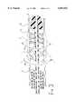
- FIGS. 1 and 2are diagrammatic representations of two stages in positioning an endoprosthesis according to the invention in an anatomical conduit.
- FIG. 3is a diagrammatic representation of another embodiment wherein angle .sub. ⁇ varies along the length of the endoprosthesis.
- FIG. 4is a graph showing the relationship between .sub. ⁇ (angle of intersection between two filaments of a stent) and the radial force (corresponding to the resistance of the stent to radial pressure thereof), established for a braided stent according to the state of the art and for a stent according to the invention.
- FIG. 1shows the general appearance of a device used for positioning an endoprosthesis according to the invention.
- framework 1 of the endoprosthesisis represented here.
- what appears here as a simple stentmay include an external and/or internal coating.
- the framework 1is made up of a braid of interlaced metal filaments.
- the particular feature of the endoprosthesis according to the inventionlies in the design of its framework, which involves the effects of a braided, naturally elastic structure, and the particular physical properties of the filaments from which it is made, combined with a phase transition effect.
- the filaments forming the braided frameworkare made from a specific alloy (in this case a Ni/Ti alloy) which, by virtue of a suitable treatment which is described hereinafter, undergoes, at a predetermined temperature, close to that of a warm-blooded organism, a reversible transition of its crystal structure, entailing a radical change in its mechanical characteristics.
- a specific alloyin this case a Ni/Ti alloy
- the metal of the framework 1 in its initial state(that is to say, below its phase transition temperature) appears perfectly ductile.
- the operatorcan very easily manipulate the endoprosthesis without fear of damaging it, breaking up the structure or disrupting the arrangement of the filaments. He can in particular set the endoprosthesis to the appropriate dimension by cutting it and compressing it radially (the effect of which is to bring the filaments up close to one another, their angle of intersection tending at this moment towards a negligible value close to zero).
- FIG. 1shows the distal end of the applicator after the latter has been introduced percutaneously into an anatomical conduit 6, in such a way as to bring the endoprosthesis to the site to be treated 7.
- the radial stressceases to apply, and, by virtue of the inherent elasticity of the braided structure, the framework 1 dilates to its nominal diameter, which corresponds substantially to that of the anatomical conduit 6.
- This changeexerts its effects at the moment when the framework 1 deploys, this corresponding to an increase in the value of the angle of intersection between the filaments.
- the filamentsthus participate in two ways in the opening out of the braided structure: there is an important synergistic effect between the deployment of the braided structure of the framework and the rigidification of the filaments due to their state transition.
- the endoprosthesiswhich, until the moment of release, exhibited very great flexibility, perfectly adapted for its insertion into the sinuosities of anatomical conduits, is thus rigidified and, quasi-instantaneously, perfectly capable not only of exerting an adequate pressure on the inner wall of the anatomical conduit 6, but also of withstanding the external stresses which this anatomical conduit 6 will necessarily suffer.
- the two combined effectsreinforce each other and permit a complete expansion of the endoprosthesis without trauma, a fact which in the long term is beneficial to the patient.
- the number of the filaments forming the framework 1 of the endoprosthesiscan be reduced, or, optionally, it is possible to use filaments of smaller diameter than in the braided endoprostheses according to the prior art, which fact leads to a substantial reduction in the diameter of the stent in the compressed state, and thus of the applicator, and increases the flexibility.
- This designalso brings with it other appreciable advantages, particularly for the positioning in the anatomical conduits of large diameter.
- the frameworkmade light (hence a reduction of the diameter in the applicator), but in addition the risk of radial non-deployment of the endoprosthesis is considerably reduced.
- FIG. 2shows the final angle .sub. ⁇ formed between the braided filaments when the framework is deployed radially.
- Trialshave demonstrated excellent adaptation of the endoprostheses according to the invention, especially for values of .sub. ⁇ of between 30 and 95°, and, optimally, in a range of 50 to 90°. In this range of angles, the difference in length between the compressed endoprosthesis (see FIG. 1) and the released endoprosthesis (see FIG. 2) is proportionally small.
- the diameter of the endoprosthesis(represented here as quasi-cylindrical) can vary along its length, and that as a consequence the angle .sub. ⁇ can also vary depending on the particular section of the endoprosthesis.
- FIG. 3displays an endoprosthesis according to the invention, wherein the pitch varies along the length, causing .sub. ⁇ to adopt different values, in the present case .sub. ⁇ 1 and .sub. ⁇ 2.
- a low value of .sub. ⁇makes it possible to reduce in particular the phenomena of friction at the moment of release and to better adapt the endoprosthesis to the biomechanical characteristics of the anatomical conduits.
- the manufacture of the framework of the endoprosthesis according to the inventioninvolves a limited number of operations, which has favourable repercussions on the production costs.
- the present shape memory filamentremains flexible and does not exhibit the rigidity of a traditionally conditioned shape-memory filament: it attains a resistance to rupture of barely 1500 N/mm 2 .
- the manufacture of the framework of an endoprosthesis according to the inventiongenerally comprises the following operations:
- the origin of the shape memoryis the existence of a reversible crystal change which takes place during cycles of heating/cooling of the specimen.
- austeniteIs characterized by a unit cell of high symmetry (it occupies a greater volume without mass transfer).
- martensitehas a cell of lesser symmetry and occupies a minimum volume.
- This phasemay appear in several variants.
- composition of the alloy(in which the nickel is present in a proportion varying between 52 and 56% by weight) plays an important role in determining the optimum parameters.
- the braided structureis prepared by fixing it on a metal bar with a diameter in relation to the nominal diameter of the endoprosthesis, or by introducing It inside a hollow mould.
- the wholeundergoes a thermal treatment at between 400 and 600° C. for an appropriate length of time (generally of the order of 10 minutes), which operation is followed by air cooling.
- the martensitic transformation temperatureis then situated between 30 and 40° C.
- a treatment time of 10 minutes at 500° C.is applied, and the maximum stiffening is obtained around 37° C.
- the thermal treatmentcan, if appropriate, be repeated in order to eliminate the residual austenite.
- the present stentis also able to withstand very high radial solicitations.
- Table 1 hereinbelowpermits comparison of the resistance to radial pressure of various endoprosthesis frameworks.
- the specimensare brought to a temperature of 37° C., either using a thermostatic bath or air.
- a very fine filamentof approximately 0.10 mm in diameter, is wound round each framework. One end of this filament is fixed to the base of the apparatus and the other is fixed to the upper part of the apparatus which is removable.
- This upper partconsists of a probe which simultaneously measures the force exerted on the specimens and the corresponding displacements.
- the resulting valueis determined (in Newton) using a computer program.
- nickel/titanium filaments usedare covered, following the present thermal treatment, with a layer of titanium oxide which ensures the passivation of the metal (by way of comparison, the metal surfaces of cobalt alloy structures must be passivated by subsequent treatment with nitric or phosphoric acid).
- the endoprostheses provided with a framework according to the inventionare non-traumatizing and simple to trim, which makes it easy to adjust their length from one case to another, if necessary at the actual site of an intervention, starting from segments of standardized length, which facilitates the packaging of the framework elements and of the endoprostheses themselves.
- curve Ashows off a virtually linear relationship between angle .sub. ⁇ and the radial force F.
- Curve Bon the contrary, exhibits a virtually constant value of F between 60° and 90° (flat segment of the curve), significantly above the corresponding values on curve A, then a slightly increasing value between 90° and 104°.
- the practitionerthus has at his disposal a stent that simultaneously exhibits a high resistance to radial pressure and a low length decrease when released in place.
- the present stentthus mimics an active component of the circulatory system. As a consequence, the possibilities of rejections and other side-effects are lowered.
- Another proved advantageis that the stent remains even over long terms close to its nominal diameter while classical braided stents are known to have a tendency to distend the walls of the vessels, causing as a counter-reaction a stretch of the adjacent sections of the arteries.
Landscapes
- Health & Medical Sciences (AREA)
- Engineering & Computer Science (AREA)
- Biomedical Technology (AREA)
- Life Sciences & Earth Sciences (AREA)
- General Health & Medical Sciences (AREA)
- Transplantation (AREA)
- Heart & Thoracic Surgery (AREA)
- Vascular Medicine (AREA)
- Cardiology (AREA)
- Animal Behavior & Ethology (AREA)
- Oral & Maxillofacial Surgery (AREA)
- Public Health (AREA)
- Veterinary Medicine (AREA)
- Media Introduction/Drainage Providing Device (AREA)
- Prostheses (AREA)
- Transition And Organic Metals Composition Catalysts For Addition Polymerization (AREA)
- Superconductors And Manufacturing Methods Therefor (AREA)
- Diaphragms For Electromechanical Transducers (AREA)
- Saccharide Compounds (AREA)
Abstract
Description
TABLE I ______________________________________ Stents according to the invention (37° C.) Cobalt alloy stents ______________________________________ Value of 32.5° 35° 45° 55° 53° angle α/2 Length 80 mm 80 mm 80 mm Initial 8.1 30.1 8.2.15 30.5 diameter (mm) Radial Force N Diameter under stress (mm) 0 8.1 30.1 8.15 8.2 30.5 0,20 7.98 30.5 0,40 7.91 30.2 0,60 7.3 29.8 0,80 6.98 26.1 1,00 6.2 23.54 1,20 5.7 20.05 1,40 4.9 19.4 1,60 3.9 16.36 1,80 3.2 12.6 ______________________________________
Claims (21)
Applications Claiming Priority (4)
| Application Number | Priority Date | Filing Date | Title |
|---|---|---|---|
| BE09700461 | 1997-05-27 | ||
| BE9700461ABE1011180A6 (en) | 1997-05-27 | 1997-05-27 | Luminal endoprosthesis AUTO EXPANDABLE. |
| EP97202698 | 1997-09-02 | ||
| EP97202698AEP0880946A1 (en) | 1997-05-27 | 1997-09-02 | Self-expanding endoprostheses |
Publications (1)
| Publication Number | Publication Date |
|---|---|
| US6051021Atrue US6051021A (en) | 2000-04-18 |
Family
ID=3890540
Family Applications (1)
| Application Number | Title | Priority Date | Filing Date |
|---|---|---|---|
| US09/083,974Expired - LifetimeUS6051021A (en) | 1997-05-27 | 1998-05-26 | Self-expanding endoprosthesis |
Country Status (16)
| Country | Link |
|---|---|
| US (1) | US6051021A (en) |
| EP (2) | EP0880946A1 (en) |
| JP (1) | JP2001526575A (en) |
| KR (1) | KR100656725B1 (en) |
| CN (1) | CN1163197C (en) |
| AT (1) | ATE256440T1 (en) |
| AU (1) | AU726933B2 (en) |
| BE (1) | BE1011180A6 (en) |
| BR (1) | BR9809663A (en) |
| CA (1) | CA2291686A1 (en) |
| DE (1) | DE69820616T2 (en) |
| ES (1) | ES2213903T3 (en) |
| IL (1) | IL133120A (en) |
| PT (1) | PT986347E (en) |
| RU (1) | RU2221523C2 (en) |
| WO (1) | WO1998053762A1 (en) |
Cited By (95)
| Publication number | Priority date | Publication date | Assignee | Title |
|---|---|---|---|---|
| US6241758B1 (en) | 1999-05-28 | 2001-06-05 | Advanced Cardiovascular Systems, Inc. | Self-expanding stent delivery system and method of use |
| US6280465B1 (en) | 1999-12-30 | 2001-08-28 | Advanced Cardiovascular Systems, Inc. | Apparatus and method for delivering a self-expanding stent on a guide wire |
| US6302893B1 (en) | 1996-07-15 | 2001-10-16 | Advanced Cardiovascular Systems, Inc. | Self-expanding stent delivery system |
| US6375676B1 (en) | 1999-05-17 | 2002-04-23 | Advanced Cardiovascular Systems, Inc. | Self-expanding stent with enhanced delivery precision and stent delivery system |
| US20030024534A1 (en)* | 2001-07-26 | 2003-02-06 | Silvestri Gerard A. | Removable stent and method of using the same |
| US6544219B2 (en) | 2000-12-15 | 2003-04-08 | Advanced Cardiovascular Systems, Inc. | Catheter for placement of therapeutic devices at the ostium of a bifurcation of a body lumen |
| US6551341B2 (en) | 2001-06-14 | 2003-04-22 | Advanced Cardiovascular Systems, Inc. | Devices configured from strain hardened Ni Ti tubing |
| US6554848B2 (en) | 2000-06-02 | 2003-04-29 | Advanced Cardiovascular Systems, Inc. | Marker device for rotationally orienting a stent delivery system prior to deploying a curved self-expanding stent |
| US6572646B1 (en) | 2000-06-02 | 2003-06-03 | Advanced Cardiovascular Systems, Inc. | Curved nitinol stent for extremely tortuous anatomy |
| US6585747B1 (en) | 2000-04-14 | 2003-07-01 | Advanced Cardiovascular Systems, Inc. | Interdigitating polymeric endcap for enhanced stent retention |
| US20030139804A1 (en)* | 1995-11-27 | 2003-07-24 | Schneider (Europe) Ag, A/K/A Schneider (Europe) Gmbh | Conical stent |
| US6620191B1 (en) | 2001-03-27 | 2003-09-16 | Advanced Cardiovascular Systems, Inc. | System for releasably securing a stent on a catheter assembly and method of use |
| US6626937B1 (en) | 2000-11-14 | 2003-09-30 | Advanced Cardiovascular Systems, Inc. | Austenitic nitinol medical devices |
| US20030199920A1 (en)* | 2000-11-02 | 2003-10-23 | Boylan John F. | Devices configured from heat shaped, strain hardened nickel-titanium |
| US20030208263A1 (en)* | 1994-05-19 | 2003-11-06 | Burmeister Paul H. | Tissue supporting devices |
| US6666880B1 (en) | 2001-06-19 | 2003-12-23 | Advised Cardiovascular Systems, Inc. | Method and system for securing a coated stent to a balloon catheter |
| US6702843B1 (en)* | 2000-04-12 | 2004-03-09 | Scimed Life Systems, Inc. | Stent delivery means with balloon retraction means |
| US6706053B1 (en) | 2000-04-28 | 2004-03-16 | Advanced Cardiovascular Systems, Inc. | Nitinol alloy design for sheath deployable and re-sheathable vascular devices |
| US20040073293A1 (en)* | 1996-04-30 | 2004-04-15 | Thompson Paul J. | Three-dimensional braided covered stent |
| US20040088040A1 (en)* | 2002-11-05 | 2004-05-06 | Mangiardi Eric K. | Stent with geometry determinated functionality and method of making the same |
| US20040116996A1 (en)* | 2001-04-18 | 2004-06-17 | Lutz Freitag | Removable essentially cylindrical implants |
| US20040122511A1 (en)* | 2002-11-05 | 2004-06-24 | Mangiardi Eric K. | Coated stent with geometry determinated functionality and method of making the same |
| US20040127974A1 (en)* | 2002-11-05 | 2004-07-01 | Mangiardi Eric K. | Differential covering and coating methods |
| US20040220608A1 (en)* | 2003-05-01 | 2004-11-04 | D'aquanni Peter | Radiopaque nitinol embolic protection frame |
| US20040249447A1 (en)* | 2000-12-27 | 2004-12-09 | Boylan John F. | Radiopaque and MRI compatible nitinol alloys for medical devices |
| US6979346B1 (en) | 2001-08-08 | 2005-12-27 | Advanced Cardiovascular Systems, Inc. | System and method for improved stent retention |
| US20060052816A1 (en)* | 2004-08-31 | 2006-03-09 | Cook Incorporated | Device for treating an aneurysm |
| US20060086440A1 (en)* | 2000-12-27 | 2006-04-27 | Boylan John F | Nitinol alloy design for improved mechanical stability and broader superelastic operating window |
| US7077860B2 (en) | 1997-04-24 | 2006-07-18 | Advanced Cardiovascular Systems, Inc. | Method of reducing or eliminating thrombus formation |
| US20060200222A1 (en)* | 2002-10-26 | 2006-09-07 | Alveolus, Inc. | Medical appliance delivery apparatus and method of use |
| US20060206200A1 (en)* | 2004-05-25 | 2006-09-14 | Chestnut Medical Technologies, Inc. | Flexible vascular occluding device |
| US20060258972A1 (en)* | 2005-05-13 | 2006-11-16 | Alveolus, Inc. | Delivery device with viewing window and associated method |
| US7175655B1 (en) | 2001-09-17 | 2007-02-13 | Endovascular Technologies, Inc. | Avoiding stress-induced martensitic transformation in nickel titanium alloys used in medical devices |
| US20070066992A1 (en)* | 2000-10-05 | 2007-03-22 | Scimed Life Systems, Inc. | Filter delivery and retrieval device |
| US7198675B2 (en) | 2003-09-30 | 2007-04-03 | Advanced Cardiovascular Systems | Stent mandrel fixture and method for selectively coating surfaces of a stent |
| US20070083257A1 (en)* | 2005-09-13 | 2007-04-12 | Dharmendra Pal | Aneurysm occlusion device |
| US7258891B2 (en) | 2001-06-28 | 2007-08-21 | Advanced Cardiovascular Systems, Inc. | Stent mounting assembly and a method of using the same to coat a stent |
| US20070239259A1 (en)* | 1999-12-01 | 2007-10-11 | Advanced Cardiovascular Systems Inc. | Nitinol alloy design and composition for medical devices |
| US20070249965A1 (en)* | 1990-12-18 | 2007-10-25 | Advanced Cardiovascular System, Inc. | Superelastic guiding member |
| US7297159B2 (en) | 2000-10-26 | 2007-11-20 | Advanced Cardiovascular Systems, Inc. | Selective coating of medical devices |
| US20080027532A1 (en)* | 2000-12-27 | 2008-01-31 | Abbott Cardiovascular Systems Inc. | Radiopaque nitinol alloys for medical devices |
| US20080132998A1 (en)* | 2004-09-29 | 2008-06-05 | Alveolus, Inc. | Active stent |
| US20080215131A1 (en)* | 2006-12-04 | 2008-09-04 | Cook Incorporated | Method for loading a medical device into a delivery system |
| US20080262600A1 (en)* | 1999-03-16 | 2008-10-23 | Jalisi Marc M | Multilayer stent |
| US7553377B1 (en) | 2004-04-27 | 2009-06-30 | Advanced Cardiovascular Systems, Inc. | Apparatus and method for electrostatic coating of an abluminal stent surface |
| US7563324B1 (en) | 2003-12-29 | 2009-07-21 | Advanced Cardiovascular Systems Inc. | System and method for coating an implantable medical device |
| US7604660B2 (en) | 2003-05-01 | 2009-10-20 | Merit Medical Systems, Inc. | Bifurcated medical appliance delivery apparatus and method |
| US7632307B2 (en) | 2004-12-16 | 2009-12-15 | Advanced Cardiovascular Systems, Inc. | Abluminal, multilayer coating constructs for drug-delivery stents |
| US7637934B2 (en) | 2003-03-31 | 2009-12-29 | Merit Medical Systems, Inc. | Medical appliance optical delivery and deployment apparatus and method |
| US7648727B2 (en) | 2004-08-26 | 2010-01-19 | Advanced Cardiovascular Systems, Inc. | Methods for manufacturing a coated stent-balloon assembly |
| US20100094394A1 (en)* | 2008-10-06 | 2010-04-15 | Bradley Beach | Reconstrainable stent delivery system |
| US20100125329A1 (en)* | 2000-11-02 | 2010-05-20 | Zhi Cheng Lin | Pseudoelastic stents having a drug coating and a method of producing the same |
| US7803180B2 (en) | 2005-04-04 | 2010-09-28 | Flexible Stenting Solutions, Inc. | Flexible stent |
| US20100286760A1 (en)* | 2009-04-24 | 2010-11-11 | Bradley Beach | Flexible devices |
| US20100298952A1 (en)* | 2009-05-20 | 2010-11-25 | Arsenal Medical | Medical implant |
| US7867547B2 (en) | 2005-12-19 | 2011-01-11 | Advanced Cardiovascular Systems, Inc. | Selectively coating luminal surfaces of stents |
| US7875068B2 (en) | 2002-11-05 | 2011-01-25 | Merit Medical Systems, Inc. | Removable biliary stent |
| US20110082464A1 (en)* | 2009-10-05 | 2011-04-07 | Arsenal Medical, Inc. | Polymeric Implant Delivery System |
| US20110137398A1 (en)* | 2008-04-23 | 2011-06-09 | Cook Inc. | Method of loading a medical device into a delivery system |
| US7976648B1 (en) | 2000-11-02 | 2011-07-12 | Abbott Cardiovascular Systems Inc. | Heat treatment for cold worked nitinol to impart a shape setting capability without eventually developing stress-induced martensite |
| US8003156B2 (en) | 2006-05-04 | 2011-08-23 | Advanced Cardiovascular Systems, Inc. | Rotatable support elements for stents |
| US8017237B2 (en) | 2006-06-23 | 2011-09-13 | Abbott Cardiovascular Systems, Inc. | Nanoshells on polymers |
| US8048441B2 (en) | 2007-06-25 | 2011-11-01 | Abbott Cardiovascular Systems, Inc. | Nanobead releasing medical devices |
| US8048448B2 (en) | 2006-06-15 | 2011-11-01 | Abbott Cardiovascular Systems Inc. | Nanoshells for drug delivery |
| US8147534B2 (en) | 2005-05-25 | 2012-04-03 | Tyco Healthcare Group Lp | System and method for delivering and deploying an occluding device within a vessel |
| US8267985B2 (en) | 2005-05-25 | 2012-09-18 | Tyco Healthcare Group Lp | System and method for delivering and deploying an occluding device within a vessel |
| US8273101B2 (en) | 2005-05-25 | 2012-09-25 | Tyco Healthcare Group Lp | System and method for delivering and deploying an occluding device within a vessel |
| US8394119B2 (en) | 2006-02-22 | 2013-03-12 | Covidien Lp | Stents having radiopaque mesh |
| US8398701B2 (en) | 2004-05-25 | 2013-03-19 | Covidien Lp | Flexible vascular occluding device |
| US8500794B2 (en) | 2007-08-02 | 2013-08-06 | Flexible Stenting Solutions, Inc. | Flexible stent |
| US8540765B2 (en) | 2009-05-20 | 2013-09-24 | 480 Biomedical, Inc. | Medical implant |
| US20130317600A1 (en)* | 2009-05-20 | 2013-11-28 | Maria Palasis | Drug eluting medical implant |
| US8603530B2 (en) | 2006-06-14 | 2013-12-10 | Abbott Cardiovascular Systems Inc. | Nanoshell therapy |
| US8617234B2 (en) | 2004-05-25 | 2013-12-31 | Covidien Lp | Flexible vascular occluding device |
| US8623067B2 (en) | 2004-05-25 | 2014-01-07 | Covidien Lp | Methods and apparatus for luminal stenting |
| US8992601B2 (en) | 2009-05-20 | 2015-03-31 | 480 Biomedical, Inc. | Medical implants |
| US9101507B2 (en) | 2011-05-18 | 2015-08-11 | Ralph F. Caselnova | Apparatus and method for proximal-to-distal endoluminal stent deployment |
| US9114001B2 (en) | 2012-10-30 | 2015-08-25 | Covidien Lp | Systems for attaining a predetermined porosity of a vascular device |
| US9157174B2 (en) | 2013-02-05 | 2015-10-13 | Covidien Lp | Vascular device for aneurysm treatment and providing blood flow into a perforator vessel |
| US9155647B2 (en) | 2012-07-18 | 2015-10-13 | Covidien Lp | Methods and apparatus for luminal stenting |
| US9309347B2 (en) | 2009-05-20 | 2016-04-12 | Biomedical, Inc. | Bioresorbable thermoset polyester/urethane elastomers |
| US9427339B2 (en) | 2011-10-30 | 2016-08-30 | Endospan Ltd. | Triple-collar stent-graft |
| US9452070B2 (en) | 2012-10-31 | 2016-09-27 | Covidien Lp | Methods and systems for increasing a density of a region of a vascular device |
| US9597204B2 (en) | 2011-12-04 | 2017-03-21 | Endospan Ltd. | Branched stent-graft system |
| US9675482B2 (en) | 2008-05-13 | 2017-06-13 | Covidien Lp | Braid implant delivery systems |
| US9770350B2 (en) | 2012-05-15 | 2017-09-26 | Endospan Ltd. | Stent-graft with fixation elements that are radially confined for delivery |
| US9839510B2 (en) | 2011-08-28 | 2017-12-12 | Endospan Ltd. | Stent-grafts with post-deployment variable radial displacement |
| US9918825B2 (en) | 2009-06-23 | 2018-03-20 | Endospan Ltd. | Vascular prosthesis for treating aneurysms |
| US9943427B2 (en) | 2012-11-06 | 2018-04-17 | Covidien Lp | Shaped occluding devices and methods of using the same |
| US10004618B2 (en) | 2004-05-25 | 2018-06-26 | Covidien Lp | Methods and apparatus for luminal stenting |
| US10485684B2 (en) | 2014-12-18 | 2019-11-26 | Endospan Ltd. | Endovascular stent-graft with fatigue-resistant lateral tube |
| US10568994B2 (en) | 2009-05-20 | 2020-02-25 | 480 Biomedical Inc. | Drug-eluting medical implants |
| US10603197B2 (en) | 2013-11-19 | 2020-03-31 | Endospan Ltd. | Stent system with radial-expansion locking |
| US10888414B2 (en) | 2019-03-20 | 2021-01-12 | inQB8 Medical Technologies, LLC | Aortic dissection implant |
| US20230277733A1 (en)* | 2019-09-11 | 2023-09-07 | Stryker Corporation | Intravascular devices |
Families Citing this family (11)
| Publication number | Priority date | Publication date | Assignee | Title |
|---|---|---|---|---|
| US6800073B2 (en) | 1999-10-28 | 2004-10-05 | Scimed Life Systems, Inc. | Biocompatible pharmaceutical articles |
| US6663606B1 (en) | 1999-10-28 | 2003-12-16 | Scimed Life Systems, Inc. | Biocompatible medical devices |
| US8808272B2 (en) | 1999-10-28 | 2014-08-19 | Boston Scientific Scimed, Inc. | Biocompatible medical devices |
| US6638259B1 (en)* | 1999-10-28 | 2003-10-28 | Scimed Life Systems, Inc. | Biocompatible medical devices |
| BE1013757A6 (en) | 2000-12-12 | 2002-07-02 | Frid Noureddine | Luminal endoprosthesis MODULAR. |
| US8192484B2 (en) | 2000-12-12 | 2012-06-05 | Cardiatis S.A. | Stent for blood flow improvement |
| US7794493B2 (en)* | 2004-06-30 | 2010-09-14 | Cordis Corporation | Magnetic resonance imaging compatibility alloy for implantable medical devices |
| US8337390B2 (en)* | 2008-07-30 | 2012-12-25 | Cube S.R.L. | Intracardiac device for restoring the functional elasticity of the cardiac structures, holding tool for the intracardiac device, and method for implantation of the intracardiac device in the heart |
| US9364358B2 (en) | 2012-07-27 | 2016-06-14 | Medinol Ltd. | Catheter with retractable cover and pressurized fluid |
| EP3760239B1 (en) | 2018-03-01 | 2022-11-02 | Titanium Textiles AG | Titanium matrix based on a tension-free metal warp knit fabric for guided tissue regeneration |
| BR112020017887A8 (en) | 2018-03-01 | 2023-04-11 | Llc Elastic Titanium Implants | TENSION-FREE TITANIUM METAL WARP KNITTING FABRIC FOR SURGICALLY SHAPEING SOFT TISSUES |
Citations (38)
| Publication number | Priority date | Publication date | Assignee | Title |
|---|---|---|---|---|
| US4425908A (en)* | 1981-10-22 | 1984-01-17 | Beth Israel Hospital | Blood clot filter |
| US4503569A (en)* | 1983-03-03 | 1985-03-12 | Dotter Charles T | Transluminally placed expandable graft prosthesis |
| US4512338A (en)* | 1983-01-25 | 1985-04-23 | Balko Alexander B | Process for restoring patency to body vessels |
| US4580568A (en)* | 1984-10-01 | 1986-04-08 | Cook, Incorporated | Percutaneous endovascular stent and method for insertion thereof |
| US4655771A (en)* | 1982-04-30 | 1987-04-07 | Shepherd Patents S.A. | Prosthesis comprising an expansible or contractile tubular body |
| US4665906A (en)* | 1983-10-14 | 1987-05-19 | Raychem Corporation | Medical devices incorporating sim alloy elements |
| US4681110A (en)* | 1985-12-02 | 1987-07-21 | Wiktor Dominik M | Catheter arrangement having a blood vessel liner, and method of using it |
| US4743251A (en)* | 1983-12-08 | 1988-05-10 | Henry Bocquee | Vein prothesis and method for producing same |
| US4795458A (en)* | 1987-07-02 | 1989-01-03 | Regan Barrie F | Stent for use following balloon angioplasty |
| US5037427A (en)* | 1987-03-25 | 1991-08-06 | Terumo Kabushiki Kaisha | Method of implanting a stent within a tubular organ of a living body and of removing same |
| US5061275A (en)* | 1986-04-21 | 1991-10-29 | Medinvent S.A. | Self-expanding prosthesis |
| US5067957A (en)* | 1983-10-14 | 1991-11-26 | Raychem Corporation | Method of inserting medical devices incorporating SIM alloy elements |
| WO1992019310A1 (en)* | 1991-04-26 | 1992-11-12 | Advanced Coronary Technology, Inc. | Removable heat-recoverable tissue supporting device |
| US5190546A (en)* | 1983-10-14 | 1993-03-02 | Raychem Corporation | Medical devices incorporating SIM alloy elements |
| US5201901A (en)* | 1987-10-08 | 1993-04-13 | Terumo Kabushiki Kaisha | Expansion unit and apparatus for expanding tubular organ lumen |
| US5226913A (en)* | 1988-09-01 | 1993-07-13 | Corvita Corporation | Method of making a radially expandable prosthesis |
| US5354309A (en)* | 1991-10-11 | 1994-10-11 | Angiomed Ag | Apparatus for widening a stenosis in a body cavity |
| US5395390A (en)* | 1992-05-01 | 1995-03-07 | The Beth Israel Hospital Association | Metal wire stent |
| US5405377A (en)* | 1992-02-21 | 1995-04-11 | Endotech Ltd. | Intraluminal stent |
| WO1995030385A1 (en)* | 1994-05-04 | 1995-11-16 | Regents Of The University Of Minnesota | Stent and method of making the same |
| WO1995031945A1 (en)* | 1994-05-19 | 1995-11-30 | Scimed Life Systems, Inc. | Improved tissue supporting devices |
| US5534007A (en)* | 1995-05-18 | 1996-07-09 | Scimed Life Systems, Inc. | Stent deployment catheter with collapsible sheath |
| US5540712A (en)* | 1992-05-01 | 1996-07-30 | Nitinol Medical Technologies, Inc. | Stent and method and apparatus for forming and delivering the same |
| US5562728A (en)* | 1983-12-09 | 1996-10-08 | Endovascular Tech Inc | Endovascular grafting apparatus, system and method and devices for use therewith |
| US5562725A (en)* | 1992-09-14 | 1996-10-08 | Meadox Medicals Inc. | Radially self-expanding implantable intraluminal device |
| US5575818A (en)* | 1995-02-14 | 1996-11-19 | Corvita Corporation | Endovascular stent with locking ring |
| EP0744164A1 (en)* | 1995-05-25 | 1996-11-27 | Cook Incorporated | An implantable prosthetic device |
| WO1997013475A1 (en)* | 1995-10-11 | 1997-04-17 | Schneider (Usa) Inc. | Braided composite prosthesis |
| US5624508A (en)* | 1995-05-02 | 1997-04-29 | Flomenblit; Josef | Manufacture of a two-way shape memory alloy and device |
| US5630840A (en)* | 1993-01-19 | 1997-05-20 | Schneider (Usa) Inc | Clad composite stent |
| US5674277A (en)* | 1994-12-23 | 1997-10-07 | Willy Rusch Ag | Stent for placement in a body tube |
| US5718159A (en)* | 1996-04-30 | 1998-02-17 | Schneider (Usa) Inc. | Process for manufacturing three-dimensional braided covered stent |
| US5741333A (en)* | 1995-04-12 | 1998-04-21 | Corvita Corporation | Self-expanding stent for a medical device to be introduced into a cavity of a body |
| US5782741A (en)* | 1996-11-12 | 1998-07-21 | Guidant Coropration | Two-stage treatment wire |
| US5840387A (en)* | 1995-07-28 | 1998-11-24 | Aegis Biosciences L.L.C. | Sulfonated multiblock copolymer and uses therefor |
| US5851217A (en)* | 1990-02-28 | 1998-12-22 | Medtronic, Inc. | Intralumenal drug eluting prosthesis |
| US5888201A (en)* | 1996-02-08 | 1999-03-30 | Schneider (Usa) Inc | Titanium alloy self-expanding stent |
| EP1205743A1 (en)* | 2000-06-29 | 2002-05-15 | Hogy Medical Co., Ltd. | Indicator for plasma sterilization |
Family Cites Families (6)
| Publication number | Priority date | Publication date | Assignee | Title |
|---|---|---|---|---|
| GB1205743A (en) | 1966-07-15 | 1970-09-16 | Nat Res Dev | Surgical dilator |
| FR2333487A1 (en) | 1975-12-02 | 1977-07-01 | Rhone Poulenc Ind | Implantable surgical tubing with sewable ends - has radially elastic wall including a fleece layer and reinforcement |
| US4950227A (en) | 1988-11-07 | 1990-08-21 | Boston Scientific Corporation | Stent delivery system |
| DE19508805C2 (en)* | 1995-03-06 | 2000-03-30 | Lutz Freitag | Stent for placement in a body tube with a flexible support structure made of at least two wires with different shape memory functions |
| EP0740928B1 (en) | 1995-04-12 | 2004-07-07 | Corvita Europe | Self-expanding stent for introducing a medical device in a body cavity and manufacturing process |
| RU7599U1 (en)* | 1997-12-18 | 1998-09-16 | Виктор Томович Партош | Intravascular endoprosthesis |
- 1997
- 1997-05-27BEBE9700461Apatent/BE1011180A6/ennot_activeIP Right Cessation
- 1997-09-02EPEP97202698Apatent/EP0880946A1/ennot_activeWithdrawn
- 1998
- 1998-05-26ATAT98923937Tpatent/ATE256440T1/ennot_activeIP Right Cessation
- 1998-05-26CNCNB988052539Apatent/CN1163197C/ennot_activeExpired - Lifetime
- 1998-05-26JPJP50002699Apatent/JP2001526575A/enactivePending
- 1998-05-26ESES98923937Tpatent/ES2213903T3/ennot_activeExpired - Lifetime
- 1998-05-26CACA002291686Apatent/CA2291686A1/ennot_activeAbandoned
- 1998-05-26BRBR9809663-0Apatent/BR9809663A/ennot_activeIP Right Cessation
- 1998-05-26USUS09/083,974patent/US6051021A/ennot_activeExpired - Lifetime
- 1998-05-26ILIL13312098Apatent/IL133120A/ennot_activeIP Right Cessation
- 1998-05-26RURU99125544/14Apatent/RU2221523C2/ennot_activeIP Right Cessation
- 1998-05-26EPEP98923937Apatent/EP0986347B1/ennot_activeExpired - Lifetime
- 1998-05-26PTPT98923937Tpatent/PT986347E/enunknown
- 1998-05-26AUAU76319/98Apatent/AU726933B2/ennot_activeExpired
- 1998-05-26DEDE69820616Tpatent/DE69820616T2/ennot_activeExpired - Lifetime
- 1998-05-26KRKR1019997010759Apatent/KR100656725B1/ennot_activeExpired - Lifetime
- 1998-05-26WOPCT/BE1998/000076patent/WO1998053762A1/enactiveIP Right Grant
Patent Citations (47)
| Publication number | Priority date | Publication date | Assignee | Title |
|---|---|---|---|---|
| US4425908A (en)* | 1981-10-22 | 1984-01-17 | Beth Israel Hospital | Blood clot filter |
| US4954126B1 (en)* | 1982-04-30 | 1996-05-28 | Ams Med Invent S A | Prosthesis comprising an expansible or contractile tubular body |
| US4655771A (en)* | 1982-04-30 | 1987-04-07 | Shepherd Patents S.A. | Prosthesis comprising an expansible or contractile tubular body |
| US4655771B1 (en)* | 1982-04-30 | 1996-09-10 | Medinvent Ams Sa | Prosthesis comprising an expansible or contractile tubular body |
| US4954126A (en)* | 1982-04-30 | 1990-09-04 | Shepherd Patents S.A. | Prosthesis comprising an expansible or contractile tubular body |
| US4512338A (en)* | 1983-01-25 | 1985-04-23 | Balko Alexander B | Process for restoring patency to body vessels |
| US4503569A (en)* | 1983-03-03 | 1985-03-12 | Dotter Charles T | Transluminally placed expandable graft prosthesis |
| US5597378A (en)* | 1983-10-14 | 1997-01-28 | Raychem Corporation | Medical devices incorporating SIM alloy elements |
| US5067957A (en)* | 1983-10-14 | 1991-11-26 | Raychem Corporation | Method of inserting medical devices incorporating SIM alloy elements |
| US5190546A (en)* | 1983-10-14 | 1993-03-02 | Raychem Corporation | Medical devices incorporating SIM alloy elements |
| US4665906A (en)* | 1983-10-14 | 1987-05-19 | Raychem Corporation | Medical devices incorporating sim alloy elements |
| US4743251A (en)* | 1983-12-08 | 1988-05-10 | Henry Bocquee | Vein prothesis and method for producing same |
| US5562728A (en)* | 1983-12-09 | 1996-10-08 | Endovascular Tech Inc | Endovascular grafting apparatus, system and method and devices for use therewith |
| US4580568A (en)* | 1984-10-01 | 1986-04-08 | Cook, Incorporated | Percutaneous endovascular stent and method for insertion thereof |
| US4681110A (en)* | 1985-12-02 | 1987-07-21 | Wiktor Dominik M | Catheter arrangement having a blood vessel liner, and method of using it |
| US5061275A (en)* | 1986-04-21 | 1991-10-29 | Medinvent S.A. | Self-expanding prosthesis |
| US5037427A (en)* | 1987-03-25 | 1991-08-06 | Terumo Kabushiki Kaisha | Method of implanting a stent within a tubular organ of a living body and of removing same |
| US4795458A (en)* | 1987-07-02 | 1989-01-03 | Regan Barrie F | Stent for use following balloon angioplasty |
| US5201901A (en)* | 1987-10-08 | 1993-04-13 | Terumo Kabushiki Kaisha | Expansion unit and apparatus for expanding tubular organ lumen |
| US5226913A (en)* | 1988-09-01 | 1993-07-13 | Corvita Corporation | Method of making a radially expandable prosthesis |
| US5851217A (en)* | 1990-02-28 | 1998-12-22 | Medtronic, Inc. | Intralumenal drug eluting prosthesis |
| WO1992019310A1 (en)* | 1991-04-26 | 1992-11-12 | Advanced Coronary Technology, Inc. | Removable heat-recoverable tissue supporting device |
| US5197978A (en)* | 1991-04-26 | 1993-03-30 | Advanced Coronary Technology, Inc. | Removable heat-recoverable tissue supporting device |
| US5197978B1 (en)* | 1991-04-26 | 1996-05-28 | Advanced Coronary Tech | Removable heat-recoverable tissue supporting device |
| US5354309A (en)* | 1991-10-11 | 1994-10-11 | Angiomed Ag | Apparatus for widening a stenosis in a body cavity |
| US5540713A (en)* | 1991-10-11 | 1996-07-30 | Angiomed Ag | Apparatus for widening a stenosis in a body cavity |
| US5405377A (en)* | 1992-02-21 | 1995-04-11 | Endotech Ltd. | Intraluminal stent |
| US5540712A (en)* | 1992-05-01 | 1996-07-30 | Nitinol Medical Technologies, Inc. | Stent and method and apparatus for forming and delivering the same |
| US5395390A (en)* | 1992-05-01 | 1995-03-07 | The Beth Israel Hospital Association | Metal wire stent |
| US5562725A (en)* | 1992-09-14 | 1996-10-08 | Meadox Medicals Inc. | Radially self-expanding implantable intraluminal device |
| US5630840A (en)* | 1993-01-19 | 1997-05-20 | Schneider (Usa) Inc | Clad composite stent |
| US5554181A (en)* | 1994-05-04 | 1996-09-10 | Regents Of The University Of Minnesota | Stent |
| WO1995030385A1 (en)* | 1994-05-04 | 1995-11-16 | Regents Of The University Of Minnesota | Stent and method of making the same |
| WO1995031945A1 (en)* | 1994-05-19 | 1995-11-30 | Scimed Life Systems, Inc. | Improved tissue supporting devices |
| US5674277A (en)* | 1994-12-23 | 1997-10-07 | Willy Rusch Ag | Stent for placement in a body tube |
| US5575818A (en)* | 1995-02-14 | 1996-11-19 | Corvita Corporation | Endovascular stent with locking ring |
| US5741333A (en)* | 1995-04-12 | 1998-04-21 | Corvita Corporation | Self-expanding stent for a medical device to be introduced into a cavity of a body |
| US5624508A (en)* | 1995-05-02 | 1997-04-29 | Flomenblit; Josef | Manufacture of a two-way shape memory alloy and device |
| US5534007A (en)* | 1995-05-18 | 1996-07-09 | Scimed Life Systems, Inc. | Stent deployment catheter with collapsible sheath |
| EP0744164A1 (en)* | 1995-05-25 | 1996-11-27 | Cook Incorporated | An implantable prosthetic device |
| US5840387A (en)* | 1995-07-28 | 1998-11-24 | Aegis Biosciences L.L.C. | Sulfonated multiblock copolymer and uses therefor |
| WO1997013475A1 (en)* | 1995-10-11 | 1997-04-17 | Schneider (Usa) Inc. | Braided composite prosthesis |
| US5758562A (en)* | 1995-10-11 | 1998-06-02 | Schneider (Usa) Inc. | Process for manufacturing braided composite prosthesis |
| US5888201A (en)* | 1996-02-08 | 1999-03-30 | Schneider (Usa) Inc | Titanium alloy self-expanding stent |
| US5718159A (en)* | 1996-04-30 | 1998-02-17 | Schneider (Usa) Inc. | Process for manufacturing three-dimensional braided covered stent |
| US5782741A (en)* | 1996-11-12 | 1998-07-21 | Guidant Coropration | Two-stage treatment wire |
| EP1205743A1 (en)* | 2000-06-29 | 2002-05-15 | Hogy Medical Co., Ltd. | Indicator for plasma sterilization |
Cited By (194)
| Publication number | Priority date | Publication date | Assignee | Title |
|---|---|---|---|---|
| US20070249965A1 (en)* | 1990-12-18 | 2007-10-25 | Advanced Cardiovascular System, Inc. | Superelastic guiding member |
| US20030208263A1 (en)* | 1994-05-19 | 2003-11-06 | Burmeister Paul H. | Tissue supporting devices |
| US20110184508A2 (en)* | 1994-05-19 | 2011-07-28 | Boston Scientific Scimed, Inc. | Improved tissue supporting devices |
| US20030139804A1 (en)* | 1995-11-27 | 2003-07-24 | Schneider (Europe) Ag, A/K/A Schneider (Europe) Gmbh | Conical stent |
| US6818015B2 (en) | 1995-11-27 | 2004-11-16 | Schneider (Europe) Gmbh | Conical stent |
| US7052513B2 (en) | 1996-04-30 | 2006-05-30 | Boston Scientific Scimed, Inc. | Three-dimensional braided covered stent |
| US20040073293A1 (en)* | 1996-04-30 | 2004-04-15 | Thompson Paul J. | Three-dimensional braided covered stent |
| US6302893B1 (en) | 1996-07-15 | 2001-10-16 | Advanced Cardiovascular Systems, Inc. | Self-expanding stent delivery system |
| US6576006B2 (en) | 1996-07-15 | 2003-06-10 | Advanced Cardiovascular Systems, Inc. | Self-expanding stent delivery system |
| US7077860B2 (en) | 1997-04-24 | 2006-07-18 | Advanced Cardiovascular Systems, Inc. | Method of reducing or eliminating thrombus formation |
| US20080262600A1 (en)* | 1999-03-16 | 2008-10-23 | Jalisi Marc M | Multilayer stent |
| US6860898B2 (en) | 1999-05-17 | 2005-03-01 | Advanced Cardiovascular Systems, Inc. | Self-expanding stent with enhanced delivery precision and stent delivery system |
| US6375676B1 (en) | 1999-05-17 | 2002-04-23 | Advanced Cardiovascular Systems, Inc. | Self-expanding stent with enhanced delivery precision and stent delivery system |
| US6709454B1 (en) | 1999-05-17 | 2004-03-23 | Advanced Cardiovascular Systems, Inc. | Self-expanding stent with enhanced delivery precision and stent delivery system |
| US6893458B2 (en) | 1999-05-17 | 2005-05-17 | Advanced Cardiovascular Systems, Inc. | Self-expanding stent with enhanced delivery precision and stent delivery system |
| US6241758B1 (en) | 1999-05-28 | 2001-06-05 | Advanced Cardiovascular Systems, Inc. | Self-expanding stent delivery system and method of use |
| US20070239259A1 (en)* | 1999-12-01 | 2007-10-11 | Advanced Cardiovascular Systems Inc. | Nitinol alloy design and composition for medical devices |
| US20090248130A1 (en)* | 1999-12-01 | 2009-10-01 | Abbott Cardiovascular Systems, Inc. | Nitinol alloy design and composition for vascular stents |
| US6280465B1 (en) | 1999-12-30 | 2001-08-28 | Advanced Cardiovascular Systems, Inc. | Apparatus and method for delivering a self-expanding stent on a guide wire |
| US6702843B1 (en)* | 2000-04-12 | 2004-03-09 | Scimed Life Systems, Inc. | Stent delivery means with balloon retraction means |
| US6585747B1 (en) | 2000-04-14 | 2003-07-01 | Advanced Cardiovascular Systems, Inc. | Interdigitating polymeric endcap for enhanced stent retention |
| US20040158281A1 (en)* | 2000-04-28 | 2004-08-12 | Boylan John F. | Nitinol alloy design for sheath deployable and re-sheathable vascular devices |
| US6706053B1 (en) | 2000-04-28 | 2004-03-16 | Advanced Cardiovascular Systems, Inc. | Nitinol alloy design for sheath deployable and re-sheathable vascular devices |
| US6554848B2 (en) | 2000-06-02 | 2003-04-29 | Advanced Cardiovascular Systems, Inc. | Marker device for rotationally orienting a stent delivery system prior to deploying a curved self-expanding stent |
| US20030187497A1 (en)* | 2000-06-02 | 2003-10-02 | Boylan John F. | Curved nitinol stent for extremely tortuous anatomy |
| US6572646B1 (en) | 2000-06-02 | 2003-06-03 | Advanced Cardiovascular Systems, Inc. | Curved nitinol stent for extremely tortuous anatomy |
| US20070066992A1 (en)* | 2000-10-05 | 2007-03-22 | Scimed Life Systems, Inc. | Filter delivery and retrieval device |
| US7297159B2 (en) | 2000-10-26 | 2007-11-20 | Advanced Cardiovascular Systems, Inc. | Selective coating of medical devices |
| US20030199920A1 (en)* | 2000-11-02 | 2003-10-23 | Boylan John F. | Devices configured from heat shaped, strain hardened nickel-titanium |
| US7938843B2 (en) | 2000-11-02 | 2011-05-10 | Abbott Cardiovascular Systems Inc. | Devices configured from heat shaped, strain hardened nickel-titanium |
| US20100125329A1 (en)* | 2000-11-02 | 2010-05-20 | Zhi Cheng Lin | Pseudoelastic stents having a drug coating and a method of producing the same |
| US7976648B1 (en) | 2000-11-02 | 2011-07-12 | Abbott Cardiovascular Systems Inc. | Heat treatment for cold worked nitinol to impart a shape setting capability without eventually developing stress-induced martensite |
| US6626937B1 (en) | 2000-11-14 | 2003-09-30 | Advanced Cardiovascular Systems, Inc. | Austenitic nitinol medical devices |
| US20040059410A1 (en)* | 2000-11-14 | 2004-03-25 | Cox Daniel L. | Austenitic nitinol medical devices |
| US7128758B2 (en) | 2000-11-14 | 2006-10-31 | Advanced Cardiovascular Systems, Inc. | Austenitic nitinol medical devices |
| US6544219B2 (en) | 2000-12-15 | 2003-04-08 | Advanced Cardiovascular Systems, Inc. | Catheter for placement of therapeutic devices at the ostium of a bifurcation of a body lumen |
| US20060086440A1 (en)* | 2000-12-27 | 2006-04-27 | Boylan John F | Nitinol alloy design for improved mechanical stability and broader superelastic operating window |
| US7128757B2 (en) | 2000-12-27 | 2006-10-31 | Advanced Cardiovascular, Inc. | Radiopaque and MRI compatible nitinol alloys for medical devices |
| US20080027532A1 (en)* | 2000-12-27 | 2008-01-31 | Abbott Cardiovascular Systems Inc. | Radiopaque nitinol alloys for medical devices |
| US20040249447A1 (en)* | 2000-12-27 | 2004-12-09 | Boylan John F. | Radiopaque and MRI compatible nitinol alloys for medical devices |
| US7918011B2 (en) | 2000-12-27 | 2011-04-05 | Abbott Cardiovascular Systems, Inc. | Method for providing radiopaque nitinol alloys for medical devices |
| US6620191B1 (en) | 2001-03-27 | 2003-09-16 | Advanced Cardiovascular Systems, Inc. | System for releasably securing a stent on a catheter assembly and method of use |
| US7252680B2 (en) | 2001-04-18 | 2007-08-07 | Alveolus, Inc. | Removable essentially cylindrical implants |
| US20040116996A1 (en)* | 2001-04-18 | 2004-06-17 | Lutz Freitag | Removable essentially cylindrical implants |
| US6551341B2 (en) | 2001-06-14 | 2003-04-22 | Advanced Cardiovascular Systems, Inc. | Devices configured from strain hardened Ni Ti tubing |
| US20030158575A1 (en)* | 2001-06-14 | 2003-08-21 | Boylan John F. | Devices configured from strain hardened Ni Ti tubing |
| US6666880B1 (en) | 2001-06-19 | 2003-12-23 | Advised Cardiovascular Systems, Inc. | Method and system for securing a coated stent to a balloon catheter |
| US7258891B2 (en) | 2001-06-28 | 2007-08-21 | Advanced Cardiovascular Systems, Inc. | Stent mounting assembly and a method of using the same to coat a stent |
| US20030024534A1 (en)* | 2001-07-26 | 2003-02-06 | Silvestri Gerard A. | Removable stent and method of using the same |
| US7547321B2 (en) | 2001-07-26 | 2009-06-16 | Alveolus Inc. | Removable stent and method of using the same |
| US6979346B1 (en) | 2001-08-08 | 2005-12-27 | Advanced Cardiovascular Systems, Inc. | System and method for improved stent retention |
| US8425588B2 (en) | 2001-09-17 | 2013-04-23 | Abbott Laboratories | Avoiding stress-induced martensitic transformation in nickel titanium alloys used in medical devices |
| US20110112624A1 (en)* | 2001-09-17 | 2011-05-12 | Abbott Laboratories | Avoiding Stress-Induced Martensitic Transformation in Nickel Titanium Alloys Used in Medical Devices |
| US20070162105A1 (en)* | 2001-09-17 | 2007-07-12 | Endovascular Technologies, Inc. | Avoiding stress-induced martensitic transformation in nickle titanium alloys used in medical devices |
| US7175655B1 (en) | 2001-09-17 | 2007-02-13 | Endovascular Technologies, Inc. | Avoiding stress-induced martensitic transformation in nickel titanium alloys used in medical devices |
| US7875070B2 (en) | 2001-09-17 | 2011-01-25 | Abbott Laboratories | Avoiding stress-induced martensitic transformation in nickel titanium alloys used in medical devices |
| US20060200222A1 (en)* | 2002-10-26 | 2006-09-07 | Alveolus, Inc. | Medical appliance delivery apparatus and method of use |
| US20100004732A1 (en)* | 2002-10-26 | 2010-01-07 | Merit Medical Systems Inc. | Medical appliance delivery apparatus and method of use |
| US7608099B2 (en) | 2002-10-26 | 2009-10-27 | Merit Medical Systems Inc. | Medical appliance delivery apparatus and method of use |
| US8267987B2 (en) | 2002-10-26 | 2012-09-18 | Merit Medical Systems, Inc. | Medical appliance delivery apparatus and method of use |
| US20040122511A1 (en)* | 2002-11-05 | 2004-06-24 | Mangiardi Eric K. | Coated stent with geometry determinated functionality and method of making the same |
| US20040127974A1 (en)* | 2002-11-05 | 2004-07-01 | Mangiardi Eric K. | Differential covering and coating methods |
| US7527644B2 (en) | 2002-11-05 | 2009-05-05 | Alveolus Inc. | Stent with geometry determinated functionality and method of making the same |
| US7959671B2 (en) | 2002-11-05 | 2011-06-14 | Merit Medical Systems, Inc. | Differential covering and coating methods |
| US8206436B2 (en) | 2002-11-05 | 2012-06-26 | Merit Medical Systems, Inc. | Coated stent with geometry determinated functionality and method of making the same |
| US20040088040A1 (en)* | 2002-11-05 | 2004-05-06 | Mangiardi Eric K. | Stent with geometry determinated functionality and method of making the same |
| US7875068B2 (en) | 2002-11-05 | 2011-01-25 | Merit Medical Systems, Inc. | Removable biliary stent |
| US7637942B2 (en) | 2002-11-05 | 2009-12-29 | Merit Medical Systems, Inc. | Coated stent with geometry determinated functionality and method of making the same |
| US20100057183A1 (en)* | 2003-03-31 | 2010-03-04 | Merit Medical Systems, Inc. | Medical appliance optical delivery and deployment apparatus and method |
| US8298277B2 (en) | 2003-03-31 | 2012-10-30 | Merit Medical Systems, Inc. | Medical appliance optical delivery and deployment apparatus and method |
| US7637934B2 (en) | 2003-03-31 | 2009-12-29 | Merit Medical Systems, Inc. | Medical appliance optical delivery and deployment apparatus and method |
| US7942892B2 (en) | 2003-05-01 | 2011-05-17 | Abbott Cardiovascular Systems Inc. | Radiopaque nitinol embolic protection frame |
| US20090319021A1 (en)* | 2003-05-01 | 2009-12-24 | Merit Medical Systems, Inc. | Bifurcated medical appliance delivery apparatus and method |
| US8353946B2 (en) | 2003-05-01 | 2013-01-15 | Merit Medical Systems, Inc. | Bifurcated medical appliance delivery apparatus and method |
| US20040220608A1 (en)* | 2003-05-01 | 2004-11-04 | D'aquanni Peter | Radiopaque nitinol embolic protection frame |
| US7604660B2 (en) | 2003-05-01 | 2009-10-20 | Merit Medical Systems, Inc. | Bifurcated medical appliance delivery apparatus and method |
| US20060212068A1 (en)* | 2003-05-01 | 2006-09-21 | Advanced Cardiovascular Systems, Inc. | Embolic protection device with an elongated superelastic radiopaque core member |
| US7604700B2 (en) | 2003-09-30 | 2009-10-20 | Advanced Cardiovascular Systems, Inc. | Stent mandrel fixture and method for selectively coating surfaces of a stent |
| US7198675B2 (en) | 2003-09-30 | 2007-04-03 | Advanced Cardiovascular Systems | Stent mandrel fixture and method for selectively coating surfaces of a stent |
| US8197879B2 (en) | 2003-09-30 | 2012-06-12 | Advanced Cardiovascular Systems, Inc. | Method for selectively coating surfaces of a stent |
| US7563324B1 (en) | 2003-12-29 | 2009-07-21 | Advanced Cardiovascular Systems Inc. | System and method for coating an implantable medical device |
| US7553377B1 (en) | 2004-04-27 | 2009-06-30 | Advanced Cardiovascular Systems, Inc. | Apparatus and method for electrostatic coating of an abluminal stent surface |
| US8623067B2 (en) | 2004-05-25 | 2014-01-07 | Covidien Lp | Methods and apparatus for luminal stenting |
| US8617234B2 (en) | 2004-05-25 | 2013-12-31 | Covidien Lp | Flexible vascular occluding device |
| US8398701B2 (en) | 2004-05-25 | 2013-03-19 | Covidien Lp | Flexible vascular occluding device |
| US9801744B2 (en) | 2004-05-25 | 2017-10-31 | Covidien Lp | Methods and apparatus for luminal stenting |
| US8382825B2 (en) | 2004-05-25 | 2013-02-26 | Covidien Lp | Flexible vascular occluding device |
| US20060206200A1 (en)* | 2004-05-25 | 2006-09-14 | Chestnut Medical Technologies, Inc. | Flexible vascular occluding device |
| US10765542B2 (en) | 2004-05-25 | 2020-09-08 | Covidien Lp | Methods and apparatus for luminal stenting |
| US12042411B2 (en) | 2004-05-25 | 2024-07-23 | Covidien Lp | Methods and apparatus for luminal stenting |
| US9855047B2 (en) | 2004-05-25 | 2018-01-02 | Covidien Lp | Flexible vascular occluding device |
| US11771433B2 (en) | 2004-05-25 | 2023-10-03 | Covidien Lp | Flexible vascular occluding device |
| US10918389B2 (en) | 2004-05-25 | 2021-02-16 | Covidien Lp | Flexible vascular occluding device |
| US9393021B2 (en) | 2004-05-25 | 2016-07-19 | Covidien Lp | Flexible vascular occluding device |
| US9295568B2 (en) | 2004-05-25 | 2016-03-29 | Covidien Lp | Methods and apparatus for luminal stenting |
| US10004618B2 (en) | 2004-05-25 | 2018-06-26 | Covidien Lp | Methods and apparatus for luminal stenting |
| US9125659B2 (en) | 2004-05-25 | 2015-09-08 | Covidien Lp | Flexible vascular occluding device |
| US9050205B2 (en) | 2004-05-25 | 2015-06-09 | Covidien Lp | Methods and apparatus for luminal stenting |
| US8628564B2 (en) | 2004-05-25 | 2014-01-14 | Covidien Lp | Methods and apparatus for luminal stenting |
| US7648727B2 (en) | 2004-08-26 | 2010-01-19 | Advanced Cardiovascular Systems, Inc. | Methods for manufacturing a coated stent-balloon assembly |
| US20060052816A1 (en)* | 2004-08-31 | 2006-03-09 | Cook Incorporated | Device for treating an aneurysm |
| US7887579B2 (en) | 2004-09-29 | 2011-02-15 | Merit Medical Systems, Inc. | Active stent |
| US20080132998A1 (en)* | 2004-09-29 | 2008-06-05 | Alveolus, Inc. | Active stent |
| US7632307B2 (en) | 2004-12-16 | 2009-12-15 | Advanced Cardiovascular Systems, Inc. | Abluminal, multilayer coating constructs for drug-delivery stents |
| US9592137B2 (en) | 2005-04-04 | 2017-03-14 | Flexible Stenting Solutions, Inc. | Flexible stent |
| US7803180B2 (en) | 2005-04-04 | 2010-09-28 | Flexible Stenting Solutions, Inc. | Flexible stent |
| US20060258972A1 (en)* | 2005-05-13 | 2006-11-16 | Alveolus, Inc. | Delivery device with viewing window and associated method |
| US7731654B2 (en) | 2005-05-13 | 2010-06-08 | Merit Medical Systems, Inc. | Delivery device with viewing window and associated method |
| US9204983B2 (en) | 2005-05-25 | 2015-12-08 | Covidien Lp | System and method for delivering and deploying an occluding device within a vessel |
| US9381104B2 (en) | 2005-05-25 | 2016-07-05 | Covidien Lp | System and method for delivering and deploying an occluding device within a vessel |
| US8273101B2 (en) | 2005-05-25 | 2012-09-25 | Tyco Healthcare Group Lp | System and method for delivering and deploying an occluding device within a vessel |
| US8267985B2 (en) | 2005-05-25 | 2012-09-18 | Tyco Healthcare Group Lp | System and method for delivering and deploying an occluding device within a vessel |
| US9095343B2 (en) | 2005-05-25 | 2015-08-04 | Covidien Lp | System and method for delivering and deploying an occluding device within a vessel |
| US8257421B2 (en) | 2005-05-25 | 2012-09-04 | Tyco Healthcare Group Lp | System and method for delivering and deploying an occluding device within a vessel |
| US10322018B2 (en) | 2005-05-25 | 2019-06-18 | Covidien Lp | System and method for delivering and deploying an occluding device within a vessel |
| US8236042B2 (en) | 2005-05-25 | 2012-08-07 | Tyco Healthcare Group Lp | System and method for delivering and deploying an occluding device within a vessel |
| US10064747B2 (en) | 2005-05-25 | 2018-09-04 | Covidien Lp | System and method for delivering and deploying an occluding device within a vessel |
| US9198666B2 (en) | 2005-05-25 | 2015-12-01 | Covidien Lp | System and method for delivering and deploying an occluding device within a vessel |
| US8147534B2 (en) | 2005-05-25 | 2012-04-03 | Tyco Healthcare Group Lp | System and method for delivering and deploying an occluding device within a vessel |
| US20070083257A1 (en)* | 2005-09-13 | 2007-04-12 | Dharmendra Pal | Aneurysm occlusion device |
| US8057495B2 (en) | 2005-09-13 | 2011-11-15 | Cook Medical Technologies Llc | Aneurysm occlusion device |
| US7867547B2 (en) | 2005-12-19 | 2011-01-11 | Advanced Cardiovascular Systems, Inc. | Selectively coating luminal surfaces of stents |
| US10433988B2 (en) | 2006-02-22 | 2019-10-08 | Covidien Lp | Stents having radiopaque mesh |
| US8394119B2 (en) | 2006-02-22 | 2013-03-12 | Covidien Lp | Stents having radiopaque mesh |
| US9320590B2 (en) | 2006-02-22 | 2016-04-26 | Covidien Lp | Stents having radiopaque mesh |
| US9610181B2 (en) | 2006-02-22 | 2017-04-04 | Covidien Lp | Stents having radiopaque mesh |
| US11382777B2 (en) | 2006-02-22 | 2022-07-12 | Covidien Lp | Stents having radiopaque mesh |
| US8003156B2 (en) | 2006-05-04 | 2011-08-23 | Advanced Cardiovascular Systems, Inc. | Rotatable support elements for stents |
| US8637110B2 (en) | 2006-05-04 | 2014-01-28 | Advanced Cardiovascular Systems, Inc. | Rotatable support elements for stents |
| US8741379B2 (en) | 2006-05-04 | 2014-06-03 | Advanced Cardiovascular Systems, Inc. | Rotatable support elements for stents |
| US8596215B2 (en) | 2006-05-04 | 2013-12-03 | Advanced Cardiovascular Systems, Inc. | Rotatable support elements for stents |
| US8465789B2 (en) | 2006-05-04 | 2013-06-18 | Advanced Cardiovascular Systems, Inc. | Rotatable support elements for stents |
| US8603530B2 (en) | 2006-06-14 | 2013-12-10 | Abbott Cardiovascular Systems Inc. | Nanoshell therapy |
| US8808342B2 (en) | 2006-06-14 | 2014-08-19 | Abbott Cardiovascular Systems Inc. | Nanoshell therapy |
| US8048448B2 (en) | 2006-06-15 | 2011-11-01 | Abbott Cardiovascular Systems Inc. | Nanoshells for drug delivery |
| US8017237B2 (en) | 2006-06-23 | 2011-09-13 | Abbott Cardiovascular Systems, Inc. | Nanoshells on polymers |
| US8293367B2 (en) | 2006-06-23 | 2012-10-23 | Advanced Cardiovascular Systems, Inc. | Nanoshells on polymers |
| US8592036B2 (en) | 2006-06-23 | 2013-11-26 | Abbott Cardiovascular Systems Inc. | Nanoshells on polymers |
| US8191220B2 (en) | 2006-12-04 | 2012-06-05 | Cook Medical Technologies Llc | Method for loading a medical device into a delivery system |
| US20080215131A1 (en)* | 2006-12-04 | 2008-09-04 | Cook Incorporated | Method for loading a medical device into a delivery system |
| US8048441B2 (en) | 2007-06-25 | 2011-11-01 | Abbott Cardiovascular Systems, Inc. | Nanobead releasing medical devices |
| US8500794B2 (en) | 2007-08-02 | 2013-08-06 | Flexible Stenting Solutions, Inc. | Flexible stent |
| US8888835B2 (en) | 2008-04-23 | 2014-11-18 | Cook Medical Technologies Llc | Method of loading a medical device into a delivery system |
| US20110137398A1 (en)* | 2008-04-23 | 2011-06-09 | Cook Inc. | Method of loading a medical device into a delivery system |
| US10610389B2 (en) | 2008-05-13 | 2020-04-07 | Covidien Lp | Braid implant delivery systems |
| US9675482B2 (en) | 2008-05-13 | 2017-06-13 | Covidien Lp | Braid implant delivery systems |
| US11707371B2 (en) | 2008-05-13 | 2023-07-25 | Covidien Lp | Braid implant delivery systems |
| US9149376B2 (en) | 2008-10-06 | 2015-10-06 | Cordis Corporation | Reconstrainable stent delivery system |
| US20100094394A1 (en)* | 2008-10-06 | 2010-04-15 | Bradley Beach | Reconstrainable stent delivery system |
| US10010438B2 (en) | 2008-10-06 | 2018-07-03 | Flexible Stenting Solutions, Inc. | Reconstrainable stent delivery system |
| US8636760B2 (en) | 2009-04-20 | 2014-01-28 | Covidien Lp | System and method for delivering and deploying an occluding device within a vessel |
| US20100286760A1 (en)* | 2009-04-24 | 2010-11-11 | Bradley Beach | Flexible devices |
| US8540765B2 (en) | 2009-05-20 | 2013-09-24 | 480 Biomedical, Inc. | Medical implant |
| US20100298952A1 (en)* | 2009-05-20 | 2010-11-25 | Arsenal Medical | Medical implant |
| US20130317600A1 (en)* | 2009-05-20 | 2013-11-28 | Maria Palasis | Drug eluting medical implant |
| US8137396B2 (en) | 2009-05-20 | 2012-03-20 | 480 Biomedical, Inc | Medical implant |
| US9155638B2 (en)* | 2009-05-20 | 2015-10-13 | 480 Biomedical, Inc. | Drug eluting medical implant |
| US8992601B2 (en) | 2009-05-20 | 2015-03-31 | 480 Biomedical, Inc. | Medical implants |
| US20110238162A1 (en)* | 2009-05-20 | 2011-09-29 | Arsenal Medical | Medical implant |
| US9278016B2 (en) | 2009-05-20 | 2016-03-08 | 480 Biomedical, Inc. | Medical implant |
| US9309347B2 (en) | 2009-05-20 | 2016-04-12 | Biomedical, Inc. | Bioresorbable thermoset polyester/urethane elastomers |
| US20130304177A1 (en)* | 2009-05-20 | 2013-11-14 | Maria Palasis | Drug Eluting Medical Implant |
| US10617796B2 (en) | 2009-05-20 | 2020-04-14 | Lyra Therapeutics, Inc. | Drug eluting medical implant |
| US8888840B2 (en)* | 2009-05-20 | 2014-11-18 | Boston Scientific Scimed, Inc. | Drug eluting medical implant |
| US10568994B2 (en) | 2009-05-20 | 2020-02-25 | 480 Biomedical Inc. | Drug-eluting medical implants |
| US11090148B2 (en) | 2009-06-23 | 2021-08-17 | Endospan Ltd. | Vascular prosthesis for treating aneurysms |
| US9918825B2 (en) | 2009-06-23 | 2018-03-20 | Endospan Ltd. | Vascular prosthesis for treating aneurysms |
| US20110082464A1 (en)* | 2009-10-05 | 2011-04-07 | Arsenal Medical, Inc. | Polymeric Implant Delivery System |
| US8372133B2 (en) | 2009-10-05 | 2013-02-12 | 480 Biomedical, Inc. | Polymeric implant delivery system |
| US9101507B2 (en) | 2011-05-18 | 2015-08-11 | Ralph F. Caselnova | Apparatus and method for proximal-to-distal endoluminal stent deployment |
| US9839510B2 (en) | 2011-08-28 | 2017-12-12 | Endospan Ltd. | Stent-grafts with post-deployment variable radial displacement |
| US9427339B2 (en) | 2011-10-30 | 2016-08-30 | Endospan Ltd. | Triple-collar stent-graft |
| US9597204B2 (en) | 2011-12-04 | 2017-03-21 | Endospan Ltd. | Branched stent-graft system |
| US9770350B2 (en) | 2012-05-15 | 2017-09-26 | Endospan Ltd. | Stent-graft with fixation elements that are radially confined for delivery |
| US9877856B2 (en) | 2012-07-18 | 2018-01-30 | Covidien Lp | Methods and apparatus for luminal stenting |
| US9155647B2 (en) | 2012-07-18 | 2015-10-13 | Covidien Lp | Methods and apparatus for luminal stenting |
| US9301831B2 (en) | 2012-10-30 | 2016-04-05 | Covidien Lp | Methods for attaining a predetermined porosity of a vascular device |
| US9907643B2 (en) | 2012-10-30 | 2018-03-06 | Covidien Lp | Systems for attaining a predetermined porosity of a vascular device |
| US9114001B2 (en) | 2012-10-30 | 2015-08-25 | Covidien Lp | Systems for attaining a predetermined porosity of a vascular device |
| US9452070B2 (en) | 2012-10-31 | 2016-09-27 | Covidien Lp | Methods and systems for increasing a density of a region of a vascular device |
| US10206798B2 (en) | 2012-10-31 | 2019-02-19 | Covidien Lp | Methods and systems for increasing a density of a region of a vascular device |
| US10952878B2 (en) | 2012-10-31 | 2021-03-23 | Covidien Lp | Methods and systems for increasing a density of a region of a vascular device |
| US9943427B2 (en) | 2012-11-06 | 2018-04-17 | Covidien Lp | Shaped occluding devices and methods of using the same |
| US9561122B2 (en) | 2013-02-05 | 2017-02-07 | Covidien Lp | Vascular device for aneurysm treatment and providing blood flow into a perforator vessel |
| US9157174B2 (en) | 2013-02-05 | 2015-10-13 | Covidien Lp | Vascular device for aneurysm treatment and providing blood flow into a perforator vessel |
| US10603197B2 (en) | 2013-11-19 | 2020-03-31 | Endospan Ltd. | Stent system with radial-expansion locking |
| US10485684B2 (en) | 2014-12-18 | 2019-11-26 | Endospan Ltd. | Endovascular stent-graft with fatigue-resistant lateral tube |
| US11419742B2 (en) | 2014-12-18 | 2022-08-23 | Endospan Ltd. | Endovascular stent-graft with fatigue-resistant lateral tube |
| US12193954B2 (en) | 2014-12-18 | 2025-01-14 | Endospan Ltd. | Endovascular stent-graft with fatigue-resistant lateral tube |
| US10888414B2 (en) | 2019-03-20 | 2021-01-12 | inQB8 Medical Technologies, LLC | Aortic dissection implant |
| US20230277733A1 (en)* | 2019-09-11 | 2023-09-07 | Stryker Corporation | Intravascular devices |
| US12133934B2 (en)* | 2019-09-11 | 2024-11-05 | Stryker Corporation | Intravascular devices |
| US12194199B2 (en) | 2019-09-11 | 2025-01-14 | Stryker Corporation | Intravascular devices |
| US12280181B2 (en) | 2019-09-11 | 2025-04-22 | Stryker Corporation | Intravascular devices |
Also Published As
| Publication number | Publication date |
|---|---|
| EP0986347A1 (en) | 2000-03-22 |
| CN1163197C (en) | 2004-08-25 |
| JP2001526575A (en) | 2001-12-18 |
| DE69820616T2 (en) | 2004-09-30 |
| WO1998053762A1 (en) | 1998-12-03 |
| AU726933B2 (en) | 2000-11-23 |
| RU2221523C2 (en) | 2004-01-20 |
| KR20010012796A (en) | 2001-02-26 |
| ATE256440T1 (en) | 2004-01-15 |
| ES2213903T3 (en) | 2004-09-01 |
| CA2291686A1 (en) | 1998-12-03 |
| CN1257416A (en) | 2000-06-21 |
| EP0986347B1 (en) | 2003-12-17 |
| IL133120A (en) | 2004-02-19 |
| BR9809663A (en) | 2000-07-11 |
| AU7631998A (en) | 1998-12-30 |
| EP0880946A1 (en) | 1998-12-02 |
| BE1011180A6 (en) | 1999-06-01 |
| DE69820616D1 (en) | 2004-01-29 |
| KR100656725B1 (en) | 2006-12-15 |
| IL133120A0 (en) | 2001-03-19 |
| PT986347E (en) | 2004-05-31 |
Similar Documents
| Publication | Publication Date | Title |
|---|---|---|
| US6051021A (en) | Self-expanding endoprosthesis | |
| JP4209032B2 (en) | Multi-layered stent with superelastic joint | |
| US6315791B1 (en) | Self-expanding prothesis | |
| AU772011B2 (en) | A method for making a self-expanding stent-graft | |
| US6296661B1 (en) | Self-expanding stent-graft | |
| EP0866678B1 (en) | Kink-resistant stent graft | |
| US5545210A (en) | Method of implanting a permanent shape memory alloy stent | |
| CA2144429C (en) | A radially self-expanding implantable intraluminal device | |
| US7632303B1 (en) | Variable stiffness medical devices | |
| US6361637B2 (en) | Method of making a kink resistant stent-graft | |
| US7722663B1 (en) | Anatomically correct endoluminal prostheses | |
| JP2005506112A (en) | Intraluminal device and method of making the same | |
| US20110152994A1 (en) | Implantable device | |
| CA2459516C (en) | Split-bridge stent design | |
| WO1997049353A1 (en) | A population of intraluminal prostheses having uniform characteristics and a process for making the same | |
| MXPA99010357A (en) | Self-expanding endoprosthesis | |
| HK1016058B (en) | Kink resistant stent-graft |
Legal Events
| Date | Code | Title | Description |
|---|---|---|---|
| AS | Assignment | Owner name:MEDICORP R&D BENELUX S.A., BELGIUM Free format text:ASSIGNMENT OF ASSIGNORS INTEREST;ASSIGNOR:FRID, NOUREDDINE;REEL/FRAME:009193/0766 Effective date:19980520 | |
| STCF | Information on status: patent grant | Free format text:PATENTED CASE | |
| CC | Certificate of correction | ||
| FEPP | Fee payment procedure | Free format text:PAT HOLDER NO LONGER CLAIMS SMALL ENTITY STATUS, ENTITY STATUS SET TO UNDISCOUNTED (ORIGINAL EVENT CODE: STOL); ENTITY STATUS OF PATENT OWNER: LARGE ENTITY | |
| FPAY | Fee payment | Year of fee payment:4 | |
| FPAY | Fee payment | Year of fee payment:8 | |
| AS | Assignment | Owner name:BOLTON MEDICAL, INC., FLORIDA Free format text:ASSIGNMENT OF ASSIGNORS INTEREST;ASSIGNOR:MEDICORP R&D BENELUX, S.A.;REEL/FRAME:020897/0393 Effective date:20050505 | |
| AS | Assignment | Owner name:MEDICORP R&D BENELUX SA, BELGIUM Free format text:ASSIGNMENT OF ASSIGNORS INTEREST;ASSIGNOR:BOLTON MEDICAL, INC.;REEL/FRAME:021439/0507 Effective date:20080723 | |
| FPAY | Fee payment | Year of fee payment:12 |