US6050977A - Syringe with retractable needle assembly - Google Patents
Syringe with retractable needle assemblyDownload PDFInfo
- Publication number
- US6050977A US6050977AUS09/111,325US11132598AUS6050977AUS 6050977 AUS6050977 AUS 6050977AUS 11132598 AUS11132598 AUS 11132598AUS 6050977 AUS6050977 AUS 6050977A
- Authority
- US
- United States
- Prior art keywords
- syringe
- plunger
- needle assembly
- elastic member
- hollow body
- Prior art date
- Legal status (The legal status is an assumption and is not a legal conclusion. Google has not performed a legal analysis and makes no representation as to the accuracy of the status listed.)
- Expired - Fee Related
Links
Images


Classifications
- A—HUMAN NECESSITIES
- A61—MEDICAL OR VETERINARY SCIENCE; HYGIENE
- A61M—DEVICES FOR INTRODUCING MEDIA INTO, OR ONTO, THE BODY; DEVICES FOR TRANSDUCING BODY MEDIA OR FOR TAKING MEDIA FROM THE BODY; DEVICES FOR PRODUCING OR ENDING SLEEP OR STUPOR
- A61M5/00—Devices for bringing media into the body in a subcutaneous, intra-vascular or intramuscular way; Accessories therefor, e.g. filling or cleaning devices, arm-rests
- A61M5/178—Syringes
- A61M5/31—Details
- A61M5/32—Needles; Details of needles pertaining to their connection with syringe or hub; Accessories for bringing the needle into, or holding the needle on, the body; Devices for protection of needles
- A61M5/3205—Apparatus for removing or disposing of used needles or syringes, e.g. containers; Means for protection against accidental injuries from used needles
- A61M5/321—Means for protection against accidental injuries by used needles
- A61M5/322—Retractable needles, i.e. disconnected from and withdrawn into the syringe barrel by the piston
- A61M5/3234—Fully automatic needle retraction, i.e. in which triggering of the needle does not require a deliberate action by the user
- A—HUMAN NECESSITIES
- A61—MEDICAL OR VETERINARY SCIENCE; HYGIENE
- A61M—DEVICES FOR INTRODUCING MEDIA INTO, OR ONTO, THE BODY; DEVICES FOR TRANSDUCING BODY MEDIA OR FOR TAKING MEDIA FROM THE BODY; DEVICES FOR PRODUCING OR ENDING SLEEP OR STUPOR
- A61M2205/00—General characteristics of the apparatus
- A61M2205/58—Means for facilitating use, e.g. by people with impaired vision
- A61M2205/581—Means for facilitating use, e.g. by people with impaired vision by audible feedback
Definitions
- the present inventionrelates generally to protection against an accidental sharps injury or stick from an unprotected needle. More particularly, the present invention relates to a retractable needle syringe for protection from an accidental sharps injury or stick from a used needle of the type commonly associated with medical practice. Most particularly, the present invention relates to an automatic retractable needle syringe for protection against an accidental sharps injury or stick from a used syringe.
- U.S. Pat. No. 5,209,739discloses a hypodermic needle assembly and a syringe, both having a retractable cannula.
- An elastomeric tubeis connected between the cannula and the passage to the fluid chamber.
- a separate mechanical devicemust be independently operated by the user to cause retraction of the cannula into a second compartment. Since the fluid must travel through the elastomeric tube to bypass the second compartment, there is a potential risk of injecting air directly into the patient if the elastomeric tube breaks.
- European Patent No. 0 862 A1discloses a device in which a needle is retracted into the syringe.
- the devicerequires the user to independently operate a mechanical device to cause retraction of the needle.
- the elastic memberis not preloaded and requires the user to depress the plunger to load the elastic member and thereafter continue to apply pressure on the plunger to avoid premature withdrawal of the plunger. As such, the device requires two hands for its operation.
- U.S. Pat. Nos. 5,395,337, 5,267,961, 5,190,526, 4,955,870, 4,874,382 and 4,838,869each disclose a device in which the needle is retracted by a compressive spring. In each of these devices, the spring and needle connection passes through the plunger sealing member. This results in complex sealing requirement for the plunger sealing member.
- the present inventionprovides a disposable, single use syringe which has a hollow body that is substantially open at one end and is substantially closed at its other end except for an aperture through which an injection means passes.
- a retractable needle assemblyis positioned within the hollow body so that the injection means passes out through the syringe body aperture.
- An elongated plungerwhich moves in the hollow body for injection purpose, has a preloaded elastic member on spaced apart retainer means and means for retracting the needle assembly. Upon substantial completion of the injection, the preload on the elastic member is released and the relaxing elastic member draws the injection means in through the aperture.
- FIG. 1is an exploded view of a syringe assembly in accordance with the present invention.
- FIG. 2depicts the needle assembly
- FIG. 3depicts the tip end of the plunger assembly.
- FIG. 4is a side elevation of the plunger assembly.
- FIG. 5is a cross sectional view of the plunger assembly taken along line 5--5 of FIG. 1.
- FIG. 6is a front elevational view of the automatic release member.
- FIG. 7is a cross sectional view of the automatic release member taken along line 7--7 of FIG. 6.
- FIG. 8shows a side elevation of a protective cap which may be used with the syringe.
- FIG. 9depicts a Luer-lock adapter attached to the syringe.
- FIG. 10depicts the syringe of FIG. 1 in an assembled but unused condition.
- FIG. 11is an expanded view of the cross section of the needle assembly taken along line 11--11 of FIG. 2, with the tip of the plunger inserted therein.
- FIG. 12depicts the syringe of FIG. 10 after the plunger assembly has been withdrawn.
- FIG. 13depicts the syringe of FIG. 12 after the syringe has been rotated.
- FIG. 14depicts the syringe of FIG. 13 as the sealing member begins to connect with the needle assembly.
- FIG. 15depicts the syringe of FIG. 14 upon substantial depression of the plunger assembly.
- FIG. 16depicts an expanded view of the rear portion of the syringe shown in FIG. 15.
- FIG. 17depicts an expanded view of the mated needle assembly and plunger tip of FIG. 16.
- FIG. 18depicts the syringe of FIG. 16 immediately after complete depression of the plunger assembly.
- FIG. 19depicts the syringe of FIG. 18 after it has been used and the needle has been retracted.
- FIG. 20depicts an expanded view of the rear portion of the syringe shown in FIG. 12.
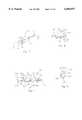
- FIG. 21is an exploded view of a second embodiment of the present invention.
- FIG. 22depicts the syringe of FIG. 21 in an assembled but unused condition.
- FIG. 23is an exploded view of a third embodiment of the present invention.
- FIG. 24is an elevation view of an alternate needle assembly for the third embodiment.
- FIG. 25is a section view taken along the line 25--25 in FIG. 24.
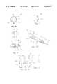
- FIG. 26is an expanded cross-sectional view of the forward portion of the syringe hollow body of the embodiment shown in FIG. 23 with the needle assembly inserted therein.
- FIG. 27is a cross-sectional view of the plunger body taken along the line 27--27 in FIG. 23.
- FIG. 28is an isometric view of the retraction hub of the third embodiment.
- FIG. 29is an enlarged cross-sectional view for the end portions of the plunger assembly of the embodiment shown in FIG. 23.
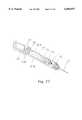
- FIG. 30depicts the syringe of FIG. 23 in an assembled but unused condition.
- FIG. 31depicts an expanded cross-sectional view of the forward portion of the syringe of FIG. 23 upon substantial depression of the plunger assembly.
- FIG. 32depicts an expanded cross-sectional view of the forward portion of the syringe shown in FIG. 23 immediately after complete depression of the plunger assembly.
- FIG. 33depicts the syringe of FIG. 23 after it has been used and the needle has been retracted.
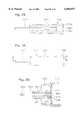
- FIG. 34depicts the syringe of FIG. 23 in an assembled but unused condition with a damper in the elastic member.
- FIG. 35is an enlarged cross-sectional view for the end portions of the plunger assembly of an alternate embodiment.
- FIG. 36depicts an expanded cross-sectional view of the forward portion of an alternate embodiment of the syringe.
- FIG. 37depicts an expanded cross-sectional view of the forward portion of the syringe shown in FIG. 36.
- the first embodiment 8is comprised generally of the syringe 10, the needle assembly 40, the automatic release member 70, the elastic member 80 and the plunger assembly 88.
- the syringe 10is comprised of a hollow body portion 12 which has a closed end 14 and an open end 24 surrounded by a grip ring 26. Integral with grip ring 26 are a stop 28 and a guiding shoulder 32 which is shown in FIG. 13. On the interior of the hollow body 12, adjacent the open end 24, is a pin 30.
- the closed end 14is defined by a truncated cone 16 which includes a truncating plane having an aperture 18.
- a retaining ring 20that retains the needle assembly 40 in position during use.
- retaining ring 20may be replaced by a plurality of projections.
- the needle assembly 40is comprised of a needle 42 which is centrally positioned in the conical projection 44.
- the conical projection 44generally complements the interior of the truncated cone 16 in the syringe 10.
- the interior surface of the truncated cone 16has a number of ridges 21 which extend from the closed end 14 to the truncating plane of the cone 16. These ridges 21 act to simplify the breaking of the seal between the needle assembly 40 and the interior surface of cone 16, thereby reducing the resistance which must be overcome to withdraw the needle assembly 40.
- a resilient collar 46Located adjacent to the projection 44 is a resilient collar 46. Immediately behind the collar 46 is the angular recess 48. Adjacent to the recess 48 is the sealing ring 50. The resilient collar 46, the angular recess 48 and the sealing ring 50 are all formed as a unitary molding of synthetic rubber.
- the interior recess 41 of needle assembly 40communicates with the hollow needle 42.
- a rectangularly configured cavity 52which is shown in detail in FIG. 2.
- the cavity 52is shaped like an arrow head with narrowly spaced walls 54 defining the shorter side of the rectangle.
- Automatic release member 70holds the elastic member 80 on the plunger member 88 in a preloaded or tensioned condition until the plunger member 88 is completely depressed.
- the elastic member 80is an elastic band which is approved for medical uses. The plunger assembly 88, the elastic member 80, and the automatic release 70 will be described in greater detail with reference to FIGS. 3-7.
- the plunger assembly 88includes a plunger portion 90 and a sealing member 110.
- the plunger portion 90has a shaft 92 which terminates at one end in the force application pad 104 and at its other end in geometrically configured tip 112.
- geometrically configured tip 112is arrow shaped with two collapsible fins 113, 115 as rod 114 extends from the end of the shaft 92.
- detents 117At the tip of rod 114 are detents 117 which allow each fin 113, 115 to collapse against the rod 114.
- the base of rod 114has two ramps 119 which assist in withdrawing tip 112 from the needle assembly cavity 52 which is in its initial position.
- a sealing member 110is placed on the rod 114 in sealing engagement therewith.
- a suitable sealing member 110is described in detail in my U.S. Pat. No. 5,338,304, which description is incorporated herein by reference.
- the shaft 92consists of 4 ribs 92A, 92B, 92C, 92D formed in a substantially cross shape with angular channels formed between adjacent ribs.
- the upper rib 92Ahas a rotation notch 94 adjacent the sealing member 110 and a first retaining notch 106 adjacent the force applicator pad 104.
- the lower rib 92Chas a second retaining notch 102 adjacent the force applicator pad 104, a third retaining notch 98 adjacent the sealing member 110, and a locking notch 100 therebetween.
- the automatic release member 70is placed on the plunger shaft 92 with its upper portion located in the first retaining notch 96 and its lower portion in the second retaining notch 102.
- the elastic member 80is attached at one end to the automatic release member 70 and at the other end to the third retaining notch 98.
- the second retaining notch 102 and the third retaining notch 98are spaced so that the elastic member 80 is preloaded, i.e. there is tension in the elastic member 80.
- the automatic release member 70is held in the second retaining notch 102 by the tensioned elastic member 80.
- the upper portionis at an approximately 45 degree angle from the lower portion and is unrestrained in the first retaining notch 96.
- the automatic release member 70is generally a beveled ring.
- the small opening 78is large enough to allow the automatic release member 70 to pass along the plunger assembly 88 until it reaches the trailing edge 108 of the first retaining notch 96.
- the trailing edge 108fits into the large opening 76, but will not pass through the small opening 78.
- the lower portion of the automatic release member 70has a notch 72 and a projection 74.
- the elastic member 80is passed through notch 72 and is hooked or secured to the projection 74.
- the automatic release member 70is then positioned on the plunger assembly 88 as previously described above.
- FIG. 8shows a protective cap 130 with threads 132 which may be used with the device 8.
- the exterior surface of truncated cone 16has threads 22 which allow the syringe 10 to be connected to the threaded cap 130 and other equipment which uses a standard Luer-lock connection.
- FIG. 9shows a Luer-lock adapter 140 with threads 142 which mate with the threads 22 on the syringe 10.
- the opposite end of the adapter 140has a second set of threads 144 and a membrane 146 which covers the end of the adapter 140 to keep it sanitary.
- the adapter 140is connected to the closed end 14 of the syringe 10.
- the needle 42punctures the membrane 146 and extends slightly past the end of the adapter 140.
- the second set of threads 144can than be used to connect the device to an intravenous line.
- the device 8operates as described hereinafter.
- FIG. 10shows the device 8 when it is first removed from its packaging and the protective cap 130 is removed.
- the plunger assembly 88is aligned within the syringe 10 such that the pin 30 is positioned in the groove between the upper rib 92A and the left rib 92B.
- the plunger assembly 88is in a first alignment in which the fins 113, 115 are horizontal and therefore are collapsed by the vertical walls 54 of the cavity 52 as shown in FIG. 11. This alignment keeps the tip 112 from locking with the needle assembly 40.
- the ramps 119help prevent the collapsed fins 113, 115 from catching on the walls 54 of the cavity.
- the plunger assembly 88is then withdrawn to the position shown in FIG. 12 to fill the hollow body 12 in a conventional manner. It will be noted that in the withdrawn position, the elastic member 80 remains in a preloaded position. Since the elastic member 80 is tensioned between two points on the plunger, the elastic member 80 does not act to withdraw or depress the plunger assembly 88. With the plunger assembly 88 withdrawn sufficiently, the pin 30 is aligned with the rotation notch 94. As shown in FIG. 13, syringe 10 and plunger assembly 88 can then be rotated relative to each other so that the fins 113, 115 are in alignment with the narrowly spaced walls 54 of the cavity 52.
- the device 8is ready for injection of the needle 42 into the patient.
- the elastic member 80is not acting to move the plunger assembly 88 in either direction. Therefore, the user is free to hold the device 8 in the traditional dart like fashion between their thumb and forefinger of one hand, and use the other hand to pinch the patient's skin at the point of insertion for subcutaneous injection, spread the skin for intermuscular injection, and stabilize the skin for IV injection. These methods of injection are the generally preferred methods in the medical field.
- the upper portion of the automatic release member 70is about to contact the finger grip 26 and the stop 28. Slightly thereafter, the upper portion of the automatic release member 70 contacts the finger grip 26 and the stop 28 and begins to move upward on the stop 28 as shown in FIG. 15.
- FIG. 16which is an expanded view of the rear of the device 8 in the position of FIG. 15, shows the trailing edge 108 of the first retaining notch 96 pinching the automatic release member 70 between itself and the stop 28.
- the fins 113, 115 of the tip 112are now aligned with the longer sides of the rectangular cavity 52.
- the fins 113, 115collapse as the tip 112 passes into the cavity 52, but upon complete depression of the plunger assembly 88, open inside the cavity 52 as shown in FIG. 17, thereby locking the plunger assembly together with the needle assembly 40.
- the notch 96 in plunger assembly 88is of sufficient length so plunger 88 can be depressed slightly further to account for any possible compression between the needle assembly 40 and the sealing member 110 and to ensure that the components mate and that all of the fluid has been discharged from the syringe 10.
- the plunger assembly 88recoils slightly and guiding shoulder 32 urges the automatic release member 70 upward until it sits against the open end 14 of the syringe and the grip ring 26 as shown is FIG. 18. Since the elastic member 80 is now tensioned between a forward point on the plunger assembly 88, and a fixed point which is separate from the plunger assembly 88 and rear of the first point, the elastic member 80 retracts the plunger assembly 88 until the entire needle 42 is retracted within the syringe 10 as shown in FIG. 19. Once the plunger assembly 88 has been completely retracted, the guiding shoulder 32 continues to urge the automatic release member 70 inwardly until it locks into locking notch 100 as shown in FIG. 20. At this point, the plunger assembly 88 is secured so that it cannot be accidentally withdrawn from the syringe 10 or pushed so the needle projects from the syringe and so that the device 8 cannot be reused.
- the components of the device 208are generally the same as in the first embodiment, however, the tip 112 and cavity 52 have different configurations, and there is an abutment 106 formed between upper rib 92A and left rib 92B.
- the tip 112is configured to have a plurality of fins 213 or alternatively, is shaped as a hemisphere as described in my earlier referenced U.S. Pat. No. 5,338,304, which description is incorporated herein by reference.
- the cavity 52is shaped to compliment each tip 112 configuration respectively.
- abutment 106is provided to prevent premature mating of the plunger tip 112 and the cavity 52.
- the plungeris initially aligned in the syringe such that abutment 106 contacts the pin 30, thereby preventing complete depression of the plunger assembly 88 and premature meeting of the tip 112 and the needle assembly 40.
- the deviceis then filled as in the first embodiment.
- the syringeis then again rotated such that the pin 30 passes through notch 94 until the pin 30 is aligned in the groove between upper rib 92A and right rib 92D.
- an abutment 106could be included in the first embodiment between upper rib 92A and left rib 92B to ensure that the tip 112 and needle assembly 40 do not prematurely mate.
- the third embodiment 308is comprised generally of the syringe 310, the needle assembly 340, the elastic member 370, and the plunger assembly 380.
- the syringe 310is comprised of a hollow body portion 312 which has a closed end 320 and an open end 324 surrounded by a grip ring 326.
- the hollow body portion 312preferably has an oval cross-section.
- the closed end 320 of the hollow body 312is defined by a cone 314 which includes a truncating plane having an aperture 318.
- the opposite end of the cone 314has a tapered portion 317, as shown in FIG. 26, the function of which will be described hereinafter.
- Proximate the tapered portion 317is an annular recess 315 which receives collar 346 of the needle assembly 340 and retains it in position during use.
- a cap receiving sleeve 316extends from the closed end 320 about the cone 314.
- the needle assembly 340is shown in FIGS. 24 and 25. It comprises a needle 342 which is centrally positioned in the conical body 344.
- the conical body 344generally complements the interior of the cone 314 of the syringe 310.
- Adjacent to the body 344is a resilient collar 346 which retains the needle assembly 340 in position and provides a fluid tight seal against the cone 314.
- An interior recess 348 of the needle assembly 340communicates with the hollow needle 342.
- an inner collar 350which defines the opening to the cavity 348.
- the cavity 348 and inner collar 350are configured to mate with a geometrically configured tip 326 on the plunger assembly 380, as will be described in more detail hereinafter.
- the plunger assembly 380includes a hollow plunger body 381, a sealing member 360, a retraction hub 320, and a plunger pad 400.
- the plunger body 381is shown in FIG. 27 and generally comprises a hollow tube 382 which is also preferably oval in cross-section to complement the syringe hollow body 312.
- One end 383 of the plunger tube 382is substantially open while the other end 385 has a reduced opening.
- An annular recess 384is provided adjacent to the substantially open end 383 to aid in connection of the plunger pad 400 to the plunger tube 382.
- Hollow shaft 390extends from the reduced opening end 385 and is axially aligned with the aperture 395.
- the free end of the shaft 390has an annular ring 392 extending therefrom.
- the plunger sealing means 360is placed on the shaft 390 and maintained in position by the ring 392, see FIG. 29.
- the plunger body 381terminates with an annular tapered projection 394 forward of ring 392. The function of the projection 394 will be described in more detail hereinafter.
- a retraction hub 320extends through the opening in the shaft 390 and into the hollow tube 382.
- the retraction hub 320generally comprises a major tubular body 322 extending between front and rear collars 324 and 330 which maintain the hub 320 in its initial position in the shaft 390 of the plunger body 381.
- the major tubular body 322is in sealing engagement with the interior of shaft 390 in this initial position.
- Extending forward of the front collar 324is a nipple 321 which includes rod 327 and tapered head 326.
- the tapered head 326provides an annular lip 329 between it and the rod 327.
- the sides of nipple 321include flattened portions 328.
- the flattened portions 328allow fluid to pass by the nipple 321 during depression of the plunger 380. This will be described in more detail hereinafter.
- Extending rearward from rear collar 330is a minor tubular body 332 which terminates in a solid retaining ring 334.
- the retaining ring 334may be comprised of a plurality of projections.
- plunger pad 400is positioned in the substantially open end 383 of the plunger tube 382.
- the plunger pad 400includes a force application pad 402 which is attached to the plunger pad body 404.
- An annular ring 406extends from the plunger pad body 404 and mates with annular recess 384 in the hollow body 382 to maintain the plunger pad 400 in position.
- Extending forward from the plunger pad body 404is a nipple 408 which has retaining ring 410 as its terminate end. Retaining ring 410 retains an end of the elastic member 370 in position.
- elastic member 370extends between the minor tubular body 332 and nipple 408 and is retained in place by retaining rings 334 and 410.
- the plunger pad body 404is preferably provided with an aperture 412 to assist in the manufacture of the plunger assembly 380.
- the elastic member 370can be attached to both the retraction hub 320 and the plunger pad 400 before insertion into the plunger body 381.
- the retraction hub 320can then be placed in the hollow tube 382 and the plunger pad 400 snap fit into its position at the rear of the plunger body 381.
- the retraction hub 320By extending a rod member through the aperture 412, the retraction hub 320 can be pushed forward until it snaps into position in the plunger shaft 390. This operation will preload elastic member 370.
- a recess 340may also be provided in the rear of the retraction hub 320 to assist in this process.
- the elastic member 370extends from the thumb pad 402 to the retraction hub 320, any air or contaminant that could possibly enter through the aperture 412 is prevented from entering the plunger hollow tube 382. This also prevents any contaminated material from escaping out the aperture 412 upon retraction of the needle assembly 340. For example, if blood or the like were to spray off of the needle 342 as it retracted into the plunger hollow tube 382, the elastic member 370 would prevent that material from exiting through the aperture 412.
- the aperture 412may also be configured such that air in the elastic member 370 will cause an audible signal, for example a whistle, as the retraction hub 320 retracts and the elastic member 370 contracts. This will signal the user that the retraction hub 320 has released and retracted.
- an audible signalfor example a whistle
- the syringe 308is assembled as shown in FIG. 30, it is ready for use.
- the syringe body 312can be filled in a conventional manner by withdrawing the plunger assembly 380.
- the elastic member 370remains in a preloaded condition when the plunger assembly is withdrawn.
- the tapered head 326 of the retraction hub 320enters the needle assembly cavity 348.
- the lip 329 of the tapered head 326is forward of and retained by the needle assembly inner collar 350.
- the retraction hub 320has moved as far into the needle assembly 340 as possible, yet the plunger body 381 has not completed its full stroke. As such, continued force on the force application pad 402 will continue to move the plunger body 381 forward.
- the flat portions 328 of tapered head 326allow the remaining fluid to pass out through the needle 342 during the final depression of the plunger body 380.
- the forward collar 324 of the retraction hubwill move inside of the plunger shaft 390. Because the retraction hub 320 is under the load of the elastic member 370 but no longer retained by the forward collar 324, the load of the elastic member 370 automatically retracts the hub 320 into the plunger hollow tube 382.
- the needle assembly 340is also retracted into the hollow plunger tube 382, as shown in FIG. 33.
- Annular tapered projection 394 on the forward end of the plunger shaft 390contacts the tapered portion 317 of cone 314 and causes it to spread slightly. This reduces the retaining force of cone 314 on the needle assembly 340 to assist retraction of the needle assembly 340 and allows easier retraction.
- the aperture 412also allows a damping material 420 to be placed inside the elastic member 370. Whether or not the damping material 420 is placed in the elastic member 370, a cap 414 may be placed over the aperture 412.
- a variety of materials, including fluids,may be used in the elastic member 370 to increase the damping effect. In most cases, air contained in the elastic member 370 will provide a sufficient damping effect and may allow some control over the speed of retraction.
- Control of retractionmay also be enhanced by leaving the aperture 412 open and allowing the user to cover the aperture, for example with their thumb, to regulate the damping effect. The user can slow the escape of the damping material to slow retraction.
- a rigid member 425for example a rod, may extend from the hub 320 and through the aperture 412 to allow the user to manually control the speed of retraction.
- the rate of retractionmay also be controlled by expanding the rear collar 330 of the retraction hub 320 until it contacts the interior of the plunger tube 382, as shown in FIGS. 36 and 37.
- the friction between the rear collar 330 and the plunger tube 382slows the rate of retraction.
- the friction forcecan be adjusted by varying any of several factors, for example the materials used or the fit between components, to provide a desired rate of retraction.
Landscapes
- Health & Medical Sciences (AREA)
- Engineering & Computer Science (AREA)
- Heart & Thoracic Surgery (AREA)
- Vascular Medicine (AREA)
- Anesthesiology (AREA)
- Biomedical Technology (AREA)
- Environmental & Geological Engineering (AREA)
- Hematology (AREA)
- Life Sciences & Earth Sciences (AREA)
- Animal Behavior & Ethology (AREA)
- General Health & Medical Sciences (AREA)
- Public Health (AREA)
- Veterinary Medicine (AREA)
- Infusion, Injection, And Reservoir Apparatuses (AREA)
Abstract
Description
Claims (49)
Priority Applications (1)
| Application Number | Priority Date | Filing Date | Title |
|---|---|---|---|
| US09/111,325US6050977A (en) | 1996-11-15 | 1998-07-07 | Syringe with retractable needle assembly |
Applications Claiming Priority (3)
| Application Number | Priority Date | Filing Date | Title |
|---|---|---|---|
| US08/749,997US5693023A (en) | 1996-11-15 | 1996-11-15 | Syringe with retractable needle assembly |
| PCT/US1997/020646WO1998020923A1 (en) | 1996-11-15 | 1997-11-14 | Syringe with retractable needle assembly |
| US09/111,325US6050977A (en) | 1996-11-15 | 1998-07-07 | Syringe with retractable needle assembly |
Related Parent Applications (1)
| Application Number | Title | Priority Date | Filing Date |
|---|---|---|---|
| PCT/US1997/020646ContinuationWO1998020923A1 (en) | 1996-11-15 | 1997-11-14 | Syringe with retractable needle assembly |
Publications (1)
| Publication Number | Publication Date |
|---|---|
| US6050977Atrue US6050977A (en) | 2000-04-18 |
Family
ID=25016097
Family Applications (2)
| Application Number | Title | Priority Date | Filing Date |
|---|---|---|---|
| US08/749,997Expired - LifetimeUS5693023A (en) | 1996-11-15 | 1996-11-15 | Syringe with retractable needle assembly |
| US09/111,325Expired - Fee RelatedUS6050977A (en) | 1996-11-15 | 1998-07-07 | Syringe with retractable needle assembly |
Family Applications Before (1)
| Application Number | Title | Priority Date | Filing Date |
|---|---|---|---|
| US08/749,997Expired - LifetimeUS5693023A (en) | 1996-11-15 | 1996-11-15 | Syringe with retractable needle assembly |
Country Status (9)
| Country | Link |
|---|---|
| US (2) | US5693023A (en) |
| EP (1) | EP1011766B1 (en) |
| CN (1) | CN1146448C (en) |
| AT (1) | ATE247497T1 (en) |
| AU (1) | AU726983B2 (en) |
| CA (1) | CA2275255C (en) |
| DE (1) | DE69724291T2 (en) |
| NZ (1) | NZ336299A (en) |
| WO (1) | WO1998020923A1 (en) |
Cited By (78)
| Publication number | Priority date | Publication date | Assignee | Title |
|---|---|---|---|---|
| US6413236B1 (en) | 1999-10-08 | 2002-07-02 | Lewis R. Van Dyke | Automatically retractable needle safety syringe |
| US6530903B2 (en) | 2000-02-24 | 2003-03-11 | Xiping Wang | Safety syringe |
| US20030050656A1 (en)* | 2000-11-10 | 2003-03-13 | Steven Schraga | Single use lancet device |
| WO2003057290A1 (en)* | 2002-01-11 | 2003-07-17 | Fa Systems Automation (S) Pte Ltd | An apparatus and process for manufacturing a medical safety device |
| US6649857B1 (en) | 2002-07-10 | 2003-11-18 | Pointe-Safe, L.L.C. | Needle destruction device |
| WO2003095003A1 (en) | 2002-05-10 | 2003-11-20 | Cambridge Biostability Ltd. | Safety injectors |
| US20040006314A1 (en)* | 2000-12-13 | 2004-01-08 | Campbell Vance D. | Syringe with retractable needle assembly |
| US20040034353A1 (en)* | 1994-03-28 | 2004-02-19 | Michelson Gary Karlin | Apparatus and method for anterior spinal stabilization |
| US20040039407A1 (en)* | 2002-04-29 | 2004-02-26 | Steven Schraga | Lancet device |
| US20040054324A1 (en)* | 2002-09-16 | 2004-03-18 | Rudy Montalvo | Syringe with retractable needle assembly |
| US6712787B1 (en) | 2000-05-19 | 2004-03-30 | Edward D. Dysarz | Self destructive safety syringe |
| US6749595B1 (en) | 2000-06-15 | 2004-06-15 | Kieran P. J. Murphy | Cement delivery needle |
| US20040122375A1 (en)* | 2002-07-02 | 2004-06-24 | Woodard, James A. | Retractable hypodermic syringe |
| US20040138619A1 (en)* | 2001-06-14 | 2004-07-15 | Kiehne Bruce Leigh | Retractable needle assembly for a catheter and which uses an elastomeric member to retract the needle |
| US20040143224A1 (en)* | 2002-01-07 | 2004-07-22 | Jeffrey Field | Method and apparatus for inhibiting fluid loss from a syringe |
| EP1461100A2 (en)* | 2000-01-26 | 2004-09-29 | Tecnedil S.r.l. | Disposable safety syringe including an automatically retractable needle |
| US20050046749A1 (en)* | 2003-08-26 | 2005-03-03 | Alps Electric Co., Ltd. | Television tuner for both analog and digital signal |
| US20050070945A1 (en)* | 1999-11-02 | 2005-03-31 | Steven Schraga | Single use lancet assembly |
| US20050080380A1 (en)* | 2003-10-14 | 2005-04-14 | Hsin-Po Hsieh | Safety syringe |
| US6887253B2 (en) | 2000-01-05 | 2005-05-03 | Steve Schraga | Lancet depth adjustment assembly |
| US6916308B2 (en) | 2000-06-08 | 2005-07-12 | Cook Incorporated | High pressure injection syringe |
| US6918918B1 (en) | 2001-08-14 | 2005-07-19 | Steven Schraga | Single use lancet assembly |
| US6939330B1 (en) | 2002-12-12 | 2005-09-06 | Medsolve Llc | Syringe insertion system |
| US6949111B2 (en) | 1998-02-13 | 2005-09-27 | Steven Schraga | Lancet device |
| EP1455859A4 (en)* | 2001-09-05 | 2005-11-16 | Futura Medical Technologies Inc | Retractable hyposermic syringe |
| WO2006029320A1 (en)* | 2004-09-09 | 2006-03-16 | Bayer Healthcare Llc | Damping system for a lancet using compressed air |
| US20060079920A1 (en)* | 2001-08-14 | 2006-04-13 | Steven Schraga | Single use lancet assembly |
| US20060167413A1 (en)* | 2003-07-04 | 2006-07-27 | Owen Mumford Limited | Automatic pen-type injector |
| US20060178686A1 (en)* | 2005-02-07 | 2006-08-10 | Steven Schraga | Single use lancet device |
| US20060253074A1 (en)* | 2005-05-09 | 2006-11-09 | Daniel Thayer | Retractable safety syringe |
| US20060264840A1 (en)* | 2005-05-09 | 2006-11-23 | Daniel Thayer | Syringe |
| WO2006129289A1 (en)* | 2005-06-01 | 2006-12-07 | Medsafe Asa | Injection syringe with automatically retractable needle |
| US20070078402A1 (en)* | 2005-08-31 | 2007-04-05 | Chung-Yu Yang | Safety Syringe |
| US20070078404A1 (en)* | 2005-07-22 | 2007-04-05 | Wei-Shui Wu | Safety syringe whose needle can be pulled back |
| USD543624S1 (en)* | 2005-12-07 | 2007-05-29 | Khalaj Ben M | Syringe's plunger locking/unlocking device |
| US20070250003A1 (en)* | 2006-04-03 | 2007-10-25 | Bare Rex O | Fluid activated retractable safety syringe |
| US20070255212A1 (en)* | 2006-04-20 | 2007-11-01 | Jeffrey Smith | Plunger activated vacuum release mechanism for a syringe |
| US20070260181A1 (en)* | 2006-04-19 | 2007-11-08 | Jeffrey Smith | Vacuum actuated small volume syringe |
| US20070260180A1 (en)* | 2006-05-05 | 2007-11-08 | Jeffrey Smith | Syringe |
| US20080021296A1 (en)* | 2004-10-21 | 2008-01-24 | Creaven John P | Sensor-Dispensing Device And Mechanism For Extracting Sensor |
| US20080027381A1 (en)* | 2006-05-24 | 2008-01-31 | Jeffrey Smith | Syringe |
| US20080097306A1 (en)* | 2006-08-29 | 2008-04-24 | Jeffrey Smith | Sterilized syringe |
| US20080114307A1 (en)* | 2006-11-06 | 2008-05-15 | Jeffrey Smith | Puncturable membrane for safety syringe |
| US20080167625A1 (en)* | 2006-12-29 | 2008-07-10 | Stephen Earhart | Process for creating a stop surface on a syringe plunger rod |
| JP2008535589A (en)* | 2005-04-15 | 2008-09-04 | ユニトラクト シリンジ プロプライエタリイ リミテッド | Controlled retractable syringe and plunger described therein |
| US20080306981A1 (en)* | 2007-06-06 | 2008-12-11 | Oracle International Corporation | Extensible Document Transformation Language: An Innovative Way of Generating Business Document and Report |
| US20090043326A1 (en)* | 2005-03-04 | 2009-02-12 | Bayer Healthcare Llc | Lancet Release Mechanism |
| US20090082798A1 (en)* | 2005-07-14 | 2009-03-26 | Bayer Healthcare Llc | Lancing Device for One Skin Puncture |
| US20090131966A1 (en)* | 2005-06-30 | 2009-05-21 | Mohammad Kheiri | Single-puncture lancing system |
| US20090221962A1 (en)* | 2005-05-12 | 2009-09-03 | Unitract Syringe Pty Ltd. | controlled retraction syringe and plunger therefor |
| US20100178703A1 (en)* | 2007-03-12 | 2010-07-15 | Bayer Healthcare Llc | Single-sensor meter system with no sensor handling and method of using the same |
| US20100179579A1 (en)* | 2007-03-12 | 2010-07-15 | Bayer Healthcare Llc | Lancet-eject mechanism |
| AU2006246309B2 (en)* | 2005-05-12 | 2011-01-06 | Unitract Syringe Pty Ltd | Improved controlled retraction syringe and plunger therefor |
| US20110046601A1 (en)* | 2006-11-06 | 2011-02-24 | Jeffrey Smith | Puncturable membrane for safety syringe |
| US20110118771A1 (en)* | 2005-08-04 | 2011-05-19 | Tieming Ruan | Lancing Device |
| US7972301B2 (en) | 2006-04-03 | 2011-07-05 | Safeshot Technologies, Llc | Safety needle syringe braking system |
| US7985216B2 (en) | 2004-03-16 | 2011-07-26 | Dali Medical Devices Ltd. | Medicinal container engagement and automatic needle device |
| US20110196300A1 (en)* | 2004-11-22 | 2011-08-11 | Intelliject, Inc. | Devices, systems and methods for medicament delivery |
| US8277422B2 (en) | 2010-07-23 | 2012-10-02 | Safeshot Technologies, Llc | Multi-chambered retractable safety syringe |
| US8376998B2 (en) | 2003-09-17 | 2013-02-19 | Elcam Medical Agricultural Cooperative Association Ltd. | Automatic injection device |
| US8425462B2 (en) | 2004-11-22 | 2013-04-23 | Intelliject, Inc. | Devices, systems, and methods for medicament delivery |
| US8627816B2 (en) | 2011-02-28 | 2014-01-14 | Intelliject, Inc. | Medicament delivery device for administration of opioid antagonists including formulations for naloxone |
| US8715309B2 (en) | 2002-04-29 | 2014-05-06 | Steven Schraga | Lancet device |
| US8814896B2 (en) | 1999-11-02 | 2014-08-26 | Stat Medical Devices, Inc. | Single use lancet assembly |
| US8939943B2 (en) | 2011-01-26 | 2015-01-27 | Kaleo, Inc. | Medicament delivery device for administration of opioid antagonists including formulations for naloxone |
| US9056170B2 (en) | 2004-11-22 | 2015-06-16 | Kaleo, Inc. | Devices, systems and methods for medicament delivery |
| US9055898B2 (en) | 2005-03-04 | 2015-06-16 | Bayer Healthcare Llc | Lancet release mechanism |
| US9084849B2 (en) | 2011-01-26 | 2015-07-21 | Kaleo, Inc. | Medicament delivery devices for administration of a medicament within a prefilled syringe |
| US9517307B2 (en) | 2014-07-18 | 2016-12-13 | Kaleo, Inc. | Devices and methods for delivering opioid antagonists including formulations for naloxone |
| USD806246S1 (en) | 2016-02-25 | 2017-12-26 | Steven Schraga | Lancet cover |
| US10071203B2 (en) | 2004-11-22 | 2018-09-11 | Kaleo, Inc. | Devices, systems and methods for medicament delivery |
| US10576206B2 (en) | 2015-06-30 | 2020-03-03 | Kaleo, Inc. | Auto-injectors for administration of a medicament within a prefilled syringe |
| US10688244B2 (en) | 2016-12-23 | 2020-06-23 | Kaleo, Inc. | Medicament delivery device and methods for delivering drugs to infants and children |
| US10737028B2 (en) | 2004-11-22 | 2020-08-11 | Kaleo, Inc. | Devices, systems and methods for medicament delivery |
| US11167087B2 (en) | 2019-08-09 | 2021-11-09 | Kaleo, Inc. | Devices and methods for delivery of substances within a prefilled syringe |
| WO2022233706A1 (en)* | 2021-05-07 | 2022-11-10 | Shl Medical Ag | A component and a sub-assembly for a medicament delivery |
| US11590286B2 (en) | 2004-11-22 | 2023-02-28 | Kaleo, Inc. | Devices, systems and methods for medicament delivery |
| US12268847B1 (en) | 2021-02-10 | 2025-04-08 | Kaleo, Inc. | Devices and methods for delivery of substances within a medicament container |
Families Citing this family (32)
| Publication number | Priority date | Publication date | Assignee | Title |
|---|---|---|---|---|
| US6090131A (en)* | 1997-09-25 | 2000-07-18 | Daley; Robert J. | Bioabsorbable staples |
| US5902319A (en)* | 1997-09-25 | 1999-05-11 | Daley; Robert J. | Bioabsorbable staples |
| TW359621B (en)* | 1998-04-10 | 1999-06-01 | Wen-Neng Liu | Safe injector with injection needle pull-back this invention provides a safe injector with injection needle pull-back which comprises: a needle cylinder, a plunger and an injection needle |
| US6120526A (en)* | 1999-01-29 | 2000-09-19 | Daley; Robert J. | Delivery devices for bioabsorbable staples |
| CA2278390C (en)* | 1999-07-19 | 2003-10-07 | Yu-Hau Chang-Lai | Safety syringe |
| US6656164B1 (en)* | 1999-09-07 | 2003-12-02 | Computer Controlled Syringe, Inc. | Retractable needle device |
| CA2394328A1 (en) | 1999-12-13 | 2001-06-14 | Futura Medical Technologies, Inc. | Syringe with retractable needle assembly |
| US6093171A (en)* | 1999-12-30 | 2000-07-25 | Huang; Wu-Shun | Safety syringe |
| US6193687B1 (en)* | 2000-01-25 | 2001-02-27 | Pi-Chang Lo | Safety hypodermic syringe |
| US6461328B2 (en)* | 2000-12-21 | 2002-10-08 | Uniqsafe Medical Technology Group Ltd. | Safety syringe |
| MY119705A (en)* | 2000-12-26 | 2005-07-29 | Wang Lin | Safety syringe |
| US6540763B2 (en) | 2001-02-20 | 2003-04-01 | Medisys Asia Pacific Pte Ltd. | Lancet device with retractable sharps member |
| US6719736B2 (en)* | 2001-04-06 | 2004-04-13 | Margie M. Collins | Dental syringe with disposable needle assembly and reusable plunger assembly |
| TW475449U (en)* | 2001-05-22 | 2002-02-01 | Chiou Jiu Chuen | Rotation sleeve control type pull-back safe injector |
| AU781969B2 (en)* | 2001-05-22 | 2005-06-23 | Chiu, Chu-Chun | Safety syringe with retractable needle holder |
| US6409702B1 (en)* | 2001-05-31 | 2002-06-25 | Li-Hua Lu | Plunger and needle holder of safety hypodermic syringe |
| US6488657B1 (en)* | 2001-09-21 | 2002-12-03 | M.K. Meditech Co., Ltd. | Needle holder positioning structure for safety hypodermic syringe |
| US6468246B1 (en)* | 2001-11-27 | 2002-10-22 | M.K. Meditech Co., Ltd. | Needle holder mounting arrangement for safety hypodermic syringe |
| WO2003045480A1 (en)* | 2001-11-30 | 2003-06-05 | Novo Nordisk A/S | A safety needle assembly |
| US7364569B2 (en)* | 2002-11-22 | 2008-04-29 | Life Shield Products Inc | Retractable safe syringe |
| US6613016B1 (en)* | 2003-01-21 | 2003-09-02 | Jen Chuan Ku | Safety hypodermic syringe |
| AU2005336322A1 (en)* | 2005-09-06 | 2007-03-15 | Global Medisafe Holdings Pty Limited | Single use safety syringe having a retractable needle |
| CN100581606C (en)* | 2005-10-10 | 2010-01-20 | 王治明 | Safety syringe |
| US7798994B2 (en)* | 2005-11-15 | 2010-09-21 | Becton, Dickinson And Company | Needle shield to septum interconnect |
| CN101433742B (en)* | 2007-11-12 | 2011-04-27 | 许明正 | Disposable injection syringe with pre-store medicament |
| CN102458521B (en)* | 2009-06-04 | 2014-06-04 | 诺沃—诺迪斯克保健股份有限公司 | Mixing device with piston coupling arrangement |
| US20140088500A1 (en)* | 2011-06-29 | 2014-03-27 | Sunwell Global Limited | Safety syringe |
| EP2823841A1 (en) | 2013-07-09 | 2015-01-14 | Sanofi-Aventis Deutschland GmbH | Autoinjector |
| EP2923714A1 (en) | 2014-03-28 | 2015-09-30 | Sanofi-Aventis Deutschland GmbH | Autoinjector triggered by skin contact |
| CN105214181B (en)* | 2014-07-04 | 2018-06-26 | 许沛扬 | Safety injector and its needle body needle stand pumpback device |
| CA2960278A1 (en)* | 2014-09-11 | 2016-03-17 | Psivida Us, Inc. | Injector apparatus |
| CN105413017B (en)* | 2015-12-30 | 2018-12-28 | 华东交通大学 | Disposable, self-destroying syringe |
Citations (26)
| Publication number | Priority date | Publication date | Assignee | Title |
|---|---|---|---|---|
| US4820278A (en)* | 1988-01-13 | 1989-04-11 | The Boeing Company | Non-contaminating renewable syringe |
| US4838869A (en)* | 1987-08-29 | 1989-06-13 | Allard Edward F | Retractable needle syringe |
| US4874382A (en)* | 1987-10-15 | 1989-10-17 | Servetus Partnership | Safety syringe |
| EP0354824A2 (en)* | 1988-08-01 | 1990-02-14 | Joseph Labouze | Non rensable syringe |
| US4917679A (en)* | 1988-09-12 | 1990-04-17 | Kronner Richard F | Syringe with protective sleeve |
| US4955870A (en)* | 1988-08-23 | 1990-09-11 | Ridderheim Kristen A | Hypodermic syringe with retractable needle |
| EP0480862A1 (en)* | 1990-10-09 | 1992-04-15 | Adolfo Ibanez Garcia | Single use syringe with automatic safety mechanism |
| US5120310A (en)* | 1991-04-03 | 1992-06-09 | Shaw Thomas J | Nonreusable syringe |
| EP0505330A1 (en)* | 1991-03-18 | 1992-09-23 | PROFARM S.p.A. | Selflocking syringe |
| FR2675999A1 (en)* | 1991-04-30 | 1992-11-06 | Ferras Jean | Safety syringe |
| US5188613A (en)* | 1991-04-03 | 1993-02-23 | Shaw Thomas J | Nonreusable syringe with safety indicator |
| US5190526A (en)* | 1992-09-18 | 1993-03-02 | Murray Kenneth W | Hypodermic safety syringe with retracting needle system |
| WO1993006880A1 (en)* | 1991-10-04 | 1993-04-15 | Retrax, Inc. | Retractable syringe |
| US5209739A (en)* | 1992-06-23 | 1993-05-11 | Leon Talalay | Hypodermic needle |
| US5267961A (en)* | 1991-04-03 | 1993-12-07 | Shaw Thomas J | Nonreusable syringe with safety indicator |
| US5320606A (en)* | 1993-03-17 | 1994-06-14 | Jore Matthew B | Single use hypodermic safety syringe |
| US5338304A (en)* | 1992-06-15 | 1994-08-16 | Adventec, Inc. | Needle protected syringe |
| US5385551A (en)* | 1993-09-22 | 1995-01-31 | Shaw; Thomas J. | Nonreusable medical device with front retraction |
| US5389076A (en)* | 1994-04-05 | 1995-02-14 | Shaw; Thomas J. | Single use medical device with retraction mechanism |
| US5395337A (en)* | 1993-08-31 | 1995-03-07 | Clemens; Anton H. | Needle retraction system |
| WO1995011713A1 (en)* | 1993-10-28 | 1995-05-04 | Lok-Tek Syringe Pty Ltd | Hypodermic syringe with retractable needle mount |
| US5423758A (en)* | 1993-12-16 | 1995-06-13 | Shaw; Thomas J. | Retractable fluid collection device |
| US5480385A (en)* | 1995-01-10 | 1996-01-02 | Specialized Health Products, Inc. | Self retracting medical needle apparatus and methods |
| WO1996004030A1 (en)* | 1994-08-05 | 1996-02-15 | Paola Danesi | Single-use syringe with retractable needle |
| EP0704225A2 (en)* | 1994-09-28 | 1996-04-03 | Becton, Dickinson and Company | Retractable needle syringe |
| US5656031A (en)* | 1995-01-10 | 1997-08-12 | Specialized Health Products, Inc. | Medical syringe and self retracting needle apparatus |
- 1996
- 1996-11-15USUS08/749,997patent/US5693023A/ennot_activeExpired - Lifetime
- 1997
- 1997-11-14DEDE69724291Tpatent/DE69724291T2/ennot_activeExpired - Lifetime
- 1997-11-14CACA002275255Apatent/CA2275255C/ennot_activeExpired - Fee Related
- 1997-11-14NZNZ336299Apatent/NZ336299A/enunknown
- 1997-11-14AUAU52548/98Apatent/AU726983B2/ennot_activeCeased
- 1997-11-14ATAT97947479Tpatent/ATE247497T1/ennot_activeIP Right Cessation
- 1997-11-14CNCNB971813973Apatent/CN1146448C/ennot_activeExpired - Fee Related
- 1997-11-14WOPCT/US1997/020646patent/WO1998020923A1/enactiveIP Right Grant
- 1997-11-14EPEP97947479Apatent/EP1011766B1/ennot_activeExpired - Lifetime
- 1998
- 1998-07-07USUS09/111,325patent/US6050977A/ennot_activeExpired - Fee Related
Patent Citations (26)
| Publication number | Priority date | Publication date | Assignee | Title |
|---|---|---|---|---|
| US4838869A (en)* | 1987-08-29 | 1989-06-13 | Allard Edward F | Retractable needle syringe |
| US4874382A (en)* | 1987-10-15 | 1989-10-17 | Servetus Partnership | Safety syringe |
| US4820278A (en)* | 1988-01-13 | 1989-04-11 | The Boeing Company | Non-contaminating renewable syringe |
| EP0354824A2 (en)* | 1988-08-01 | 1990-02-14 | Joseph Labouze | Non rensable syringe |
| US4955870A (en)* | 1988-08-23 | 1990-09-11 | Ridderheim Kristen A | Hypodermic syringe with retractable needle |
| US4917679A (en)* | 1988-09-12 | 1990-04-17 | Kronner Richard F | Syringe with protective sleeve |
| EP0480862A1 (en)* | 1990-10-09 | 1992-04-15 | Adolfo Ibanez Garcia | Single use syringe with automatic safety mechanism |
| EP0505330A1 (en)* | 1991-03-18 | 1992-09-23 | PROFARM S.p.A. | Selflocking syringe |
| US5120310A (en)* | 1991-04-03 | 1992-06-09 | Shaw Thomas J | Nonreusable syringe |
| US5188613A (en)* | 1991-04-03 | 1993-02-23 | Shaw Thomas J | Nonreusable syringe with safety indicator |
| US5267961A (en)* | 1991-04-03 | 1993-12-07 | Shaw Thomas J | Nonreusable syringe with safety indicator |
| FR2675999A1 (en)* | 1991-04-30 | 1992-11-06 | Ferras Jean | Safety syringe |
| WO1993006880A1 (en)* | 1991-10-04 | 1993-04-15 | Retrax, Inc. | Retractable syringe |
| US5338304A (en)* | 1992-06-15 | 1994-08-16 | Adventec, Inc. | Needle protected syringe |
| US5209739A (en)* | 1992-06-23 | 1993-05-11 | Leon Talalay | Hypodermic needle |
| US5190526A (en)* | 1992-09-18 | 1993-03-02 | Murray Kenneth W | Hypodermic safety syringe with retracting needle system |
| US5320606A (en)* | 1993-03-17 | 1994-06-14 | Jore Matthew B | Single use hypodermic safety syringe |
| US5395337A (en)* | 1993-08-31 | 1995-03-07 | Clemens; Anton H. | Needle retraction system |
| US5385551A (en)* | 1993-09-22 | 1995-01-31 | Shaw; Thomas J. | Nonreusable medical device with front retraction |
| WO1995011713A1 (en)* | 1993-10-28 | 1995-05-04 | Lok-Tek Syringe Pty Ltd | Hypodermic syringe with retractable needle mount |
| US5423758A (en)* | 1993-12-16 | 1995-06-13 | Shaw; Thomas J. | Retractable fluid collection device |
| US5389076A (en)* | 1994-04-05 | 1995-02-14 | Shaw; Thomas J. | Single use medical device with retraction mechanism |
| WO1996004030A1 (en)* | 1994-08-05 | 1996-02-15 | Paola Danesi | Single-use syringe with retractable needle |
| EP0704225A2 (en)* | 1994-09-28 | 1996-04-03 | Becton, Dickinson and Company | Retractable needle syringe |
| US5480385A (en)* | 1995-01-10 | 1996-01-02 | Specialized Health Products, Inc. | Self retracting medical needle apparatus and methods |
| US5656031A (en)* | 1995-01-10 | 1997-08-12 | Specialized Health Products, Inc. | Medical syringe and self retracting needle apparatus |
Cited By (155)
| Publication number | Priority date | Publication date | Assignee | Title |
|---|---|---|---|---|
| US20040034353A1 (en)* | 1994-03-28 | 2004-02-19 | Michelson Gary Karlin | Apparatus and method for anterior spinal stabilization |
| US6949111B2 (en) | 1998-02-13 | 2005-09-27 | Steven Schraga | Lancet device |
| US6413236B1 (en) | 1999-10-08 | 2002-07-02 | Lewis R. Van Dyke | Automatically retractable needle safety syringe |
| US20050070945A1 (en)* | 1999-11-02 | 2005-03-31 | Steven Schraga | Single use lancet assembly |
| US8034069B2 (en) | 1999-11-02 | 2011-10-11 | Steven Schraga | Single use lancet assembly |
| US8353924B2 (en) | 1999-11-02 | 2013-01-15 | Stat Medical Devices, Inc. | Single use lancet assembly |
| US8814896B2 (en) | 1999-11-02 | 2014-08-26 | Stat Medical Devices, Inc. | Single use lancet assembly |
| US20100305598A1 (en)* | 1999-11-02 | 2010-12-02 | Steven Schraga | single use lancet assembly |
| US7678126B2 (en) | 2000-01-05 | 2010-03-16 | Steven Schraga | Lancet depth adjustment assembly |
| US6887253B2 (en) | 2000-01-05 | 2005-05-03 | Steve Schraga | Lancet depth adjustment assembly |
| US20100198243A1 (en)* | 2000-01-05 | 2010-08-05 | Steven Schraga | Lancet depth adjustment assembly |
| EP1461100A2 (en)* | 2000-01-26 | 2004-09-29 | Tecnedil S.r.l. | Disposable safety syringe including an automatically retractable needle |
| US6530903B2 (en) | 2000-02-24 | 2003-03-11 | Xiping Wang | Safety syringe |
| US6712787B1 (en) | 2000-05-19 | 2004-03-30 | Edward D. Dysarz | Self destructive safety syringe |
| US20060116643A1 (en)* | 2000-06-08 | 2006-06-01 | Dixon Christopher G | High pressure injection syringe |
| US7604618B2 (en) | 2000-06-08 | 2009-10-20 | Cook Incorporated | High pressure injection syringe |
| US6916308B2 (en) | 2000-06-08 | 2005-07-12 | Cook Incorporated | High pressure injection syringe |
| US6749595B1 (en) | 2000-06-15 | 2004-06-15 | Kieran P. J. Murphy | Cement delivery needle |
| US20030050656A1 (en)* | 2000-11-10 | 2003-03-13 | Steven Schraga | Single use lancet device |
| US7575583B1 (en) | 2000-11-10 | 2009-08-18 | Steven Schraga | Single use lancet device |
| US6958072B2 (en) | 2000-11-10 | 2005-10-25 | Steven Schraga | Single use lancet device |
| US20040006314A1 (en)* | 2000-12-13 | 2004-01-08 | Campbell Vance D. | Syringe with retractable needle assembly |
| US7044931B2 (en) | 2000-12-13 | 2006-05-16 | Hypoguard Usa Inc. | Syringe with retractable needle assembly |
| US20040138619A1 (en)* | 2001-06-14 | 2004-07-15 | Kiehne Bruce Leigh | Retractable needle assembly for a catheter and which uses an elastomeric member to retract the needle |
| US20060079920A1 (en)* | 2001-08-14 | 2006-04-13 | Steven Schraga | Single use lancet assembly |
| US8048097B2 (en) | 2001-08-14 | 2011-11-01 | Steven Schraga | Single use lancet assembly |
| US6918918B1 (en) | 2001-08-14 | 2005-07-19 | Steven Schraga | Single use lancet assembly |
| EP1455859A4 (en)* | 2001-09-05 | 2005-11-16 | Futura Medical Technologies Inc | Retractable hyposermic syringe |
| US20040143224A1 (en)* | 2002-01-07 | 2004-07-22 | Jeffrey Field | Method and apparatus for inhibiting fluid loss from a syringe |
| WO2003057290A1 (en)* | 2002-01-11 | 2003-07-17 | Fa Systems Automation (S) Pte Ltd | An apparatus and process for manufacturing a medical safety device |
| US8715309B2 (en) | 2002-04-29 | 2014-05-06 | Steven Schraga | Lancet device |
| US8118825B2 (en) | 2002-04-29 | 2012-02-21 | Steven Schraga | Lancet device |
| US20040039407A1 (en)* | 2002-04-29 | 2004-02-26 | Steven Schraga | Lancet device |
| US6808507B2 (en) | 2002-05-10 | 2004-10-26 | Cambridge Biostability Ltd. | Safety injectors |
| WO2003095003A1 (en) | 2002-05-10 | 2003-11-20 | Cambridge Biostability Ltd. | Safety injectors |
| US20090043263A1 (en)* | 2002-07-02 | 2009-02-12 | Woodard Jr James A | Retractable hypodermic syringe |
| US20040122375A1 (en)* | 2002-07-02 | 2004-06-24 | Woodard, James A. | Retractable hypodermic syringe |
| US7393343B2 (en) | 2002-07-02 | 2008-07-01 | Hypoguard Usa Inc. | Retractable hypodermic syringe |
| US6649857B1 (en) | 2002-07-10 | 2003-11-18 | Pointe-Safe, L.L.C. | Needle destruction device |
| EP1549365A4 (en)* | 2002-09-16 | 2006-08-23 | Futura Medical Technologies Inc | Syringe with retractable needle assembly |
| US20040054324A1 (en)* | 2002-09-16 | 2004-03-18 | Rudy Montalvo | Syringe with retractable needle assembly |
| AU2003270733B2 (en)* | 2002-09-16 | 2009-01-22 | Futura Medical Technologies, Inc. | Syringe with retractable needle assembly |
| CN100448491C (en)* | 2002-09-16 | 2009-01-07 | 未来医疗技术公司 | Syringes with retractable needle parts |
| US7494479B2 (en) | 2002-09-16 | 2009-02-24 | Medsolve Technologies, Inc. | Syringe with retractable needle assembly |
| US6939330B1 (en) | 2002-12-12 | 2005-09-06 | Medsolve Llc | Syringe insertion system |
| US20060167413A1 (en)* | 2003-07-04 | 2006-07-27 | Owen Mumford Limited | Automatic pen-type injector |
| US7563252B2 (en)* | 2003-07-04 | 2009-07-21 | Owen Mumford Limited | Automatic pen-type injector |
| US20050046749A1 (en)* | 2003-08-26 | 2005-03-03 | Alps Electric Co., Ltd. | Television tuner for both analog and digital signal |
| US8376998B2 (en) | 2003-09-17 | 2013-02-19 | Elcam Medical Agricultural Cooperative Association Ltd. | Automatic injection device |
| EP2650033A2 (en) | 2003-09-17 | 2013-10-16 | Elcam Medical Agricultural Cooperative Association Ltd. | Automatic injection device |
| US11623051B2 (en) | 2003-09-17 | 2023-04-11 | E3D Agricultural Cooperative Association Ltd. | Automatic injection device |
| US20050080380A1 (en)* | 2003-10-14 | 2005-04-14 | Hsin-Po Hsieh | Safety syringe |
| US7985216B2 (en) | 2004-03-16 | 2011-07-26 | Dali Medical Devices Ltd. | Medicinal container engagement and automatic needle device |
| US20080097503A1 (en)* | 2004-09-09 | 2008-04-24 | Creaven John P | Damping System for a Lancet Using Compressed Air |
| WO2006029320A1 (en)* | 2004-09-09 | 2006-03-16 | Bayer Healthcare Llc | Damping system for a lancet using compressed air |
| US20080021296A1 (en)* | 2004-10-21 | 2008-01-24 | Creaven John P | Sensor-Dispensing Device And Mechanism For Extracting Sensor |
| US8142733B2 (en) | 2004-10-21 | 2012-03-27 | Bayer Healthcare Llc | Sensor-dispensing device and mechanism for extracting sensor |
| US9833573B2 (en) | 2004-11-22 | 2017-12-05 | Kaleo, Inc. | Devices, systems and methods for medicament delivery |
| US9056170B2 (en) | 2004-11-22 | 2015-06-16 | Kaleo, Inc. | Devices, systems and methods for medicament delivery |
| US9737669B2 (en) | 2004-11-22 | 2017-08-22 | Kaleo, Inc. | Devices, systems and methods for medicament delivery |
| US9352091B2 (en) | 2004-11-22 | 2016-05-31 | Kaleo, Inc. | Devices, systems and methods for medicament delivery |
| US8425462B2 (en) | 2004-11-22 | 2013-04-23 | Intelliject, Inc. | Devices, systems, and methods for medicament delivery |
| US8361029B2 (en) | 2004-11-22 | 2013-01-29 | Intelliject, Llc | Devices, systems and methods for medicament delivery |
| US8920377B2 (en) | 2004-11-22 | 2014-12-30 | Kaleo, Inc. | Devices, systems and methods for medicament delivery |
| US10737028B2 (en) | 2004-11-22 | 2020-08-11 | Kaleo, Inc. | Devices, systems and methods for medicament delivery |
| US10071203B2 (en) | 2004-11-22 | 2018-09-11 | Kaleo, Inc. | Devices, systems and methods for medicament delivery |
| US20110196300A1 (en)* | 2004-11-22 | 2011-08-11 | Intelliject, Inc. | Devices, systems and methods for medicament delivery |
| US10314977B2 (en) | 2004-11-22 | 2019-06-11 | Kaleo, Inc. | Devices, systems and methods for medicament delivery |
| US9149579B2 (en) | 2004-11-22 | 2015-10-06 | Kaleo, Inc. | Devices, systems and methods for medicament delivery |
| US10335549B2 (en) | 2004-11-22 | 2019-07-02 | Kaleo, Inc. | Devices, systems and methods for medicament delivery |
| US11590286B2 (en) | 2004-11-22 | 2023-02-28 | Kaleo, Inc. | Devices, systems and methods for medicament delivery |
| US10918791B2 (en) | 2005-02-01 | 2021-02-16 | Kaleo, Inc. | Devices, systems and methods for medicament delivery |
| US20060178686A1 (en)* | 2005-02-07 | 2006-08-10 | Steven Schraga | Single use lancet device |
| US9055898B2 (en) | 2005-03-04 | 2015-06-16 | Bayer Healthcare Llc | Lancet release mechanism |
| US20090043326A1 (en)* | 2005-03-04 | 2009-02-12 | Bayer Healthcare Llc | Lancet Release Mechanism |
| US9622688B2 (en) | 2005-03-04 | 2017-04-18 | Ascensia Diabetes Care Holdings Ag | Lancet-release mechanism |
| US8784444B2 (en) | 2005-03-04 | 2014-07-22 | Bayer Healthcare Llc | Lancet release mechanism |
| JP2008535589A (en)* | 2005-04-15 | 2008-09-04 | ユニトラクト シリンジ プロプライエタリイ リミテッド | Controlled retractable syringe and plunger described therein |
| US8167837B2 (en) | 2005-04-15 | 2012-05-01 | Unitract Syringe Pty Ltd. | Controlled retraction syringe and plunger therefor |
| US20090093759A1 (en)* | 2005-04-15 | 2009-04-09 | Unitract Syringe Pty Ltd | Controlled retraction syringe and plunger therefor |
| US9155845B2 (en) | 2005-05-09 | 2015-10-13 | Credence Medsystems, Inc. | Retractable safety syringe |
| US7947020B2 (en) | 2005-05-09 | 2011-05-24 | Safeshot Technologies, Llc | Retractable safety syringe |
| US20060264840A1 (en)* | 2005-05-09 | 2006-11-23 | Daniel Thayer | Syringe |
| US20060253074A1 (en)* | 2005-05-09 | 2006-11-09 | Daniel Thayer | Retractable safety syringe |
| US7572247B2 (en) | 2005-05-09 | 2009-08-11 | Safeshot Technologies, Llc | Syringe |
| US8535266B2 (en) | 2005-05-09 | 2013-09-17 | Safeshot Technologies, Llc | Retractable safety syringe |
| US20070000556A1 (en)* | 2005-05-09 | 2007-01-04 | Jeffrey Smith | Syringe |
| US20100217203A1 (en)* | 2005-05-09 | 2010-08-26 | Daniel Thayer | Retractable safety syringe |
| US8114050B2 (en)* | 2005-05-12 | 2012-02-14 | Unitract Syringe Pty Ltd | Controlled retraction syringe and plunger therefor |
| US20090221962A1 (en)* | 2005-05-12 | 2009-09-03 | Unitract Syringe Pty Ltd. | controlled retraction syringe and plunger therefor |
| AU2006246309B2 (en)* | 2005-05-12 | 2011-01-06 | Unitract Syringe Pty Ltd | Improved controlled retraction syringe and plunger therefor |
| US20090281491A1 (en)* | 2005-06-01 | 2009-11-12 | Medsafe Asa | Injection syringe with automatically retractable needle |
| WO2006129289A1 (en)* | 2005-06-01 | 2006-12-07 | Medsafe Asa | Injection syringe with automatically retractable needle |
| US20090131966A1 (en)* | 2005-06-30 | 2009-05-21 | Mohammad Kheiri | Single-puncture lancing system |
| US8333782B2 (en) | 2005-07-14 | 2012-12-18 | Bayer Healthcare Llc | Lancing device for one skin puncture |
| US20090082798A1 (en)* | 2005-07-14 | 2009-03-26 | Bayer Healthcare Llc | Lancing Device for One Skin Puncture |
| US8048098B2 (en) | 2005-07-14 | 2011-11-01 | Bayer Healthcare Llc | Lancing device for one skin puncture |
| US20070078404A1 (en)* | 2005-07-22 | 2007-04-05 | Wei-Shui Wu | Safety syringe whose needle can be pulled back |
| US20110118771A1 (en)* | 2005-08-04 | 2011-05-19 | Tieming Ruan | Lancing Device |
| US8864783B2 (en) | 2005-08-04 | 2014-10-21 | Bayer Healthcare Llc | Lancing device |
| US9375175B2 (en) | 2005-08-04 | 2016-06-28 | Ascensia Diabetes Care Holdings Ag | Lancing device |
| US8617195B2 (en) | 2005-08-04 | 2013-12-31 | Bayer Healthcare Llc | Lancing device |
| US20070078402A1 (en)* | 2005-08-31 | 2007-04-05 | Chung-Yu Yang | Safety Syringe |
| USD543624S1 (en)* | 2005-12-07 | 2007-05-29 | Khalaj Ben M | Syringe's plunger locking/unlocking device |
| US7972301B2 (en) | 2006-04-03 | 2011-07-05 | Safeshot Technologies, Llc | Safety needle syringe braking system |
| US8740855B2 (en) | 2006-04-03 | 2014-06-03 | Credence Medsystems, Inc. | Safety needle syringe braking system |
| US20070250003A1 (en)* | 2006-04-03 | 2007-10-25 | Bare Rex O | Fluid activated retractable safety syringe |
| US7806858B2 (en) | 2006-04-19 | 2010-10-05 | Safeshot Technologies, Llc | Vacuum actuated small volume syringe |
| US20100324484A1 (en)* | 2006-04-19 | 2010-12-23 | Safeshot Technologies, Llc | Vacuum Actuated Small Volume Syringe |
| US20070260181A1 (en)* | 2006-04-19 | 2007-11-08 | Jeffrey Smith | Vacuum actuated small volume syringe |
| US8273055B2 (en) | 2006-04-19 | 2012-09-25 | Safeshot Technologies, Llc | Vacuum actuated small volume syringe |
| US8152762B2 (en) | 2006-04-20 | 2012-04-10 | Safeshot Technologies, Llc | Plunger activated vacuum release mechanism for a syringe |
| US20070255212A1 (en)* | 2006-04-20 | 2007-11-01 | Jeffrey Smith | Plunger activated vacuum release mechanism for a syringe |
| US20070260180A1 (en)* | 2006-05-05 | 2007-11-08 | Jeffrey Smith | Syringe |
| US7972300B2 (en)* | 2006-05-05 | 2011-07-05 | Safeshot Technologies, Llc | Syringe |
| US20080027381A1 (en)* | 2006-05-24 | 2008-01-31 | Jeffrey Smith | Syringe |
| US8088104B2 (en) | 2006-05-24 | 2012-01-03 | Safeshot Technologies, Llc | Syringe |
| US20080097306A1 (en)* | 2006-08-29 | 2008-04-24 | Jeffrey Smith | Sterilized syringe |
| US20080114307A1 (en)* | 2006-11-06 | 2008-05-15 | Jeffrey Smith | Puncturable membrane for safety syringe |
| US20110046601A1 (en)* | 2006-11-06 | 2011-02-24 | Jeffrey Smith | Puncturable membrane for safety syringe |
| US8398601B2 (en) | 2006-11-06 | 2013-03-19 | Safeshot Technologies, Llc | Puncturable membrane for safety syringe |
| US20080167625A1 (en)* | 2006-12-29 | 2008-07-10 | Stephen Earhart | Process for creating a stop surface on a syringe plunger rod |
| US7704426B2 (en) | 2006-12-29 | 2010-04-27 | Tyco Healthcare Group Lp | Process for creating a stop surface on a syringe plunger rod |
| WO2008085380A1 (en)* | 2006-12-29 | 2008-07-17 | Tyco Healthcare Group Lp | Process for creating a stop surface on a syringe plunger rod |
| US20100179579A1 (en)* | 2007-03-12 | 2010-07-15 | Bayer Healthcare Llc | Lancet-eject mechanism |
| US8303615B2 (en) | 2007-03-12 | 2012-11-06 | Bayer Healthcare Llc | Lancet-eject mechanism |
| US20100178703A1 (en)* | 2007-03-12 | 2010-07-15 | Bayer Healthcare Llc | Single-sensor meter system with no sensor handling and method of using the same |
| US20080306981A1 (en)* | 2007-06-06 | 2008-12-11 | Oracle International Corporation | Extensible Document Transformation Language: An Innovative Way of Generating Business Document and Report |
| US8277422B2 (en) | 2010-07-23 | 2012-10-02 | Safeshot Technologies, Llc | Multi-chambered retractable safety syringe |
| US10342924B2 (en) | 2011-01-26 | 2019-07-09 | Kaleo, Inc. | Medicament delivery devices for administration of a medicament within a prefilled syringe |
| US9084849B2 (en) | 2011-01-26 | 2015-07-21 | Kaleo, Inc. | Medicament delivery devices for administration of a medicament within a prefilled syringe |
| US11426520B2 (en) | 2011-01-26 | 2022-08-30 | Kaleo, Inc. | Medicament delivery devices for administration of a medicament within a prefilled syringe |
| US8939943B2 (en) | 2011-01-26 | 2015-01-27 | Kaleo, Inc. | Medicament delivery device for administration of opioid antagonists including formulations for naloxone |
| US10238806B2 (en) | 2011-01-26 | 2019-03-26 | Kaleo, Inc. | Medicament delivery devices for administration of a medicament within a prefilled syringe |
| US12420016B2 (en) | 2011-01-26 | 2025-09-23 | Kaleo, Inc. | Medicament delivery devices for administration of a medicament within a prefilled syringe |
| US10322239B2 (en) | 2011-01-26 | 2019-06-18 | Kaleo, Inc. | Medicament delivery device for administration of opioid antagonists including formulations for naloxone |
| USD994110S1 (en) | 2011-01-26 | 2023-08-01 | Kaleo, Inc. | Medicament delivery device cover |
| US9814838B2 (en) | 2011-01-26 | 2017-11-14 | Kaleo, Inc. | Medicament delivery device for administration of opioid antagonists including formulations for naloxone |
| USD1011520S1 (en) | 2011-01-26 | 2024-01-16 | Kaleo, Inc. | Medicament delivery device and cover assembly |
| US9022022B2 (en) | 2011-02-28 | 2015-05-05 | Kaleo, Inc. | Medicament delivery device for administration of opioid antagonists including formulations for naloxone |
| US8627816B2 (en) | 2011-02-28 | 2014-01-14 | Intelliject, Inc. | Medicament delivery device for administration of opioid antagonists including formulations for naloxone |
| US9474869B2 (en) | 2011-02-28 | 2016-10-25 | Kaleo, Inc. | Medicament delivery device for administration of opioid antagonists including formulations for naloxone |
| US10143792B2 (en) | 2011-02-28 | 2018-12-04 | Kaleo, Inc. | Medicament delivery device for administration of opioid antagonists including formulations for naloxone |
| US9517307B2 (en) | 2014-07-18 | 2016-12-13 | Kaleo, Inc. | Devices and methods for delivering opioid antagonists including formulations for naloxone |
| US10220158B2 (en) | 2014-07-18 | 2019-03-05 | Kaleo, Inc. | Devices and methods for delivering opioid antagonists including formulations for naloxone |
| US10576206B2 (en) | 2015-06-30 | 2020-03-03 | Kaleo, Inc. | Auto-injectors for administration of a medicament within a prefilled syringe |
| US11517674B2 (en) | 2015-06-30 | 2022-12-06 | Kaleo, Inc. | Auto-injectors for administration of a medicament within a prefilled syringe |
| USD806246S1 (en) | 2016-02-25 | 2017-12-26 | Steven Schraga | Lancet cover |
| US10842938B2 (en) | 2016-12-23 | 2020-11-24 | Kaleo, Inc. | Medicament delivery device and methods for delivering drugs to infants and children |
| US11771830B2 (en) | 2016-12-23 | 2023-10-03 | Kaleo, Inc. | Medicament delivery device and methods for delivering drugs to infants and children |
| US10688244B2 (en) | 2016-12-23 | 2020-06-23 | Kaleo, Inc. | Medicament delivery device and methods for delivering drugs to infants and children |
| US11167087B2 (en) | 2019-08-09 | 2021-11-09 | Kaleo, Inc. | Devices and methods for delivery of substances within a prefilled syringe |
| US12017047B2 (en) | 2019-08-09 | 2024-06-25 | Kaleo, Inc. | Devices and methods for delivery of substances within a prefilled syringe |
| US12268847B1 (en) | 2021-02-10 | 2025-04-08 | Kaleo, Inc. | Devices and methods for delivery of substances within a medicament container |
| WO2022233706A1 (en)* | 2021-05-07 | 2022-11-10 | Shl Medical Ag | A component and a sub-assembly for a medicament delivery |
Also Published As
| Publication number | Publication date |
|---|---|
| EP1011766B1 (en) | 2003-08-20 |
| DE69724291T2 (en) | 2004-03-18 |
| CA2275255C (en) | 2006-08-29 |
| CN1244811A (en) | 2000-02-16 |
| CN1146448C (en) | 2004-04-21 |
| CA2275255A1 (en) | 1998-05-22 |
| AU5254898A (en) | 1998-06-03 |
| NZ336299A (en) | 2001-01-26 |
| ATE247497T1 (en) | 2003-09-15 |
| US5693023A (en) | 1997-12-02 |
| DE69724291D1 (en) | 2003-09-25 |
| AU726983B2 (en) | 2000-11-30 |
| EP1011766A1 (en) | 2000-06-28 |
| HK1029537A1 (en) | 2001-04-06 |
| WO1998020923A1 (en) | 1998-05-22 |
Similar Documents
| Publication | Publication Date | Title |
|---|---|---|
| US6050977A (en) | Syringe with retractable needle assembly | |
| US7601139B2 (en) | Spring launched needle safety clip | |
| US4966593A (en) | Disposable hypodermic syringe with retractable needle | |
| US5085642A (en) | Conveniently carried frequent use autoinjector | |
| US4950251A (en) | Simplified retractable needle syringe | |
| US7044931B2 (en) | Syringe with retractable needle assembly | |
| US20040143224A1 (en) | Method and apparatus for inhibiting fluid loss from a syringe | |
| AU2002350451A1 (en) | Spring launched needle safety clip | |
| EP1797921B1 (en) | Safety hypodermic syringe | |
| CA2394351C (en) | Syringe with retractable needle assembly | |
| HK1029537B (en) | Syringe with retractable needle assembly | |
| MXPA99005527A (en) | Syringe with retractable needle assembly | |
| WO2002066097A2 (en) | Method and apparatus for inhibiting fluid loss from a syringe | |
| WO2004082758A1 (en) | A syringe |
Legal Events
| Date | Code | Title | Description |
|---|---|---|---|
| AS | Assignment | Owner name:ADVENTEC, INC., A NEW JERSEY CORPORATION, NEW JERS Free format text:ASSIGNMENT OF ASSIGNORS INTEREST;ASSIGNOR:ADAMS, ROBERT D.;REEL/FRAME:009348/0320 Effective date:19980702 | |
| AS | Assignment | Owner name:FUTURA MEDICAL TECHNOLOGIES INC., DELAWARE Free format text:ASSIGNMENT OF ASSIGNORS INTEREST;ASSIGNOR:ADVENTEC, INC.;REEL/FRAME:010244/0459 Effective date:19990910 | |
| CC | Certificate of correction | ||
| FPAY | Fee payment | Year of fee payment:4 | |
| AS | Assignment | Owner name:GOVERNOR AND COMPANY OF THE BANK OF SCOTLAND, THE, Free format text:SECURITY AGREEMENT;ASSIGNOR:HYPOGUARD USA INC.;REEL/FRAME:014934/0762 Effective date:20040116 | |
| AS | Assignment | Owner name:HYPOGUARD USA INC., MINNESOTA Free format text:MERGER;ASSIGNOR:FUTURA MEDICAL TECHNOLOGIES, INC.;REEL/FRAME:015074/0734 Effective date:20030826 | |
| AS | Assignment | Owner name:HYPOGUARD USA, INC., MINNESOTA Free format text:RELEASE BY SECURED PARTY;ASSIGNOR:THE GOVERNOR AND COMPANY OF THE BANK OF SCOTLAND;REEL/FRAME:017619/0038 Effective date:20060511 | |
| FPAY | Fee payment | Year of fee payment:8 | |
| REMI | Maintenance fee reminder mailed | ||
| LAPS | Lapse for failure to pay maintenance fees | ||
| STCH | Information on status: patent discontinuation | Free format text:PATENT EXPIRED DUE TO NONPAYMENT OF MAINTENANCE FEES UNDER 37 CFR 1.362 | |
| FP | Lapsed due to failure to pay maintenance fee | Effective date:20120418 |