US6050969A - Pressure indicator - Google Patents
Pressure indicatorDownload PDFInfo
- Publication number
- US6050969A US6050969AUS09/062,334US6233498AUS6050969AUS 6050969 AUS6050969 AUS 6050969AUS 6233498 AUS6233498 AUS 6233498AUS 6050969 AUS6050969 AUS 6050969A
- Authority
- US
- United States
- Prior art keywords
- indicator
- shunt valve
- cam
- ferromagnetic
- pressure setting
- Prior art date
- Legal status (The legal status is an assumption and is not a legal conclusion. Google has not performed a legal analysis and makes no representation as to the accuracy of the status listed.)
- Expired - Lifetime
Links
Images


Classifications
- A—HUMAN NECESSITIES
- A61—MEDICAL OR VETERINARY SCIENCE; HYGIENE
- A61M—DEVICES FOR INTRODUCING MEDIA INTO, OR ONTO, THE BODY; DEVICES FOR TRANSDUCING BODY MEDIA OR FOR TAKING MEDIA FROM THE BODY; DEVICES FOR PRODUCING OR ENDING SLEEP OR STUPOR
- A61M27/00—Drainage appliance for wounds or the like, i.e. wound drains, implanted drains
- A61M27/002—Implant devices for drainage of body fluids from one part of the body to another
- A61M27/006—Cerebrospinal drainage; Accessories therefor, e.g. valves
- A—HUMAN NECESSITIES
- A61—MEDICAL OR VETERINARY SCIENCE; HYGIENE
- A61F—FILTERS IMPLANTABLE INTO BLOOD VESSELS; PROSTHESES; DEVICES PROVIDING PATENCY TO, OR PREVENTING COLLAPSING OF, TUBULAR STRUCTURES OF THE BODY, e.g. STENTS; ORTHOPAEDIC, NURSING OR CONTRACEPTIVE DEVICES; FOMENTATION; TREATMENT OR PROTECTION OF EYES OR EARS; BANDAGES, DRESSINGS OR ABSORBENT PADS; FIRST-AID KITS
- A61F2/00—Filters implantable into blood vessels; Prostheses, i.e. artificial substitutes or replacements for parts of the body; Appliances for connecting them with the body; Devices providing patency to, or preventing collapsing of, tubular structures of the body, e.g. stents
- A61F2/0004—Closure means for urethra or rectum, i.e. anti-incontinence devices or support slings against pelvic prolapse
- A61F2/0031—Closure means for urethra or rectum, i.e. anti-incontinence devices or support slings against pelvic prolapse for constricting the lumen; Support slings for the urethra
- A61F2/0036—Closure means for urethra or rectum, i.e. anti-incontinence devices or support slings against pelvic prolapse for constricting the lumen; Support slings for the urethra implantable
- A—HUMAN NECESSITIES
- A61—MEDICAL OR VETERINARY SCIENCE; HYGIENE
- A61F—FILTERS IMPLANTABLE INTO BLOOD VESSELS; PROSTHESES; DEVICES PROVIDING PATENCY TO, OR PREVENTING COLLAPSING OF, TUBULAR STRUCTURES OF THE BODY, e.g. STENTS; ORTHOPAEDIC, NURSING OR CONTRACEPTIVE DEVICES; FOMENTATION; TREATMENT OR PROTECTION OF EYES OR EARS; BANDAGES, DRESSINGS OR ABSORBENT PADS; FIRST-AID KITS
- A61F2250/00—Special features of prostheses classified in groups A61F2/00 - A61F2/26 or A61F2/82 or A61F9/00 or A61F11/00 or subgroups thereof
- A61F2250/0001—Means for transferring electromagnetic energy to implants
- A—HUMAN NECESSITIES
- A61—MEDICAL OR VETERINARY SCIENCE; HYGIENE
- A61F—FILTERS IMPLANTABLE INTO BLOOD VESSELS; PROSTHESES; DEVICES PROVIDING PATENCY TO, OR PREVENTING COLLAPSING OF, TUBULAR STRUCTURES OF THE BODY, e.g. STENTS; ORTHOPAEDIC, NURSING OR CONTRACEPTIVE DEVICES; FOMENTATION; TREATMENT OR PROTECTION OF EYES OR EARS; BANDAGES, DRESSINGS OR ABSORBENT PADS; FIRST-AID KITS
- A61F2250/00—Special features of prostheses classified in groups A61F2/00 - A61F2/26 or A61F2/82 or A61F9/00 or A61F11/00 or subgroups thereof
- A61F2250/0058—Additional features; Implant or prostheses properties not otherwise provided for
- A61F2250/0085—Identification means; Administration of patients
Definitions
- the present inventionrelates to devices for obtaining information from an apparatus and more particularly to a system including an implantable apparatus and a device for obtaining pressure setting information of the apparatus after implantation.
- CSFcerebrospinal fluid
- fluid shunt systemsinclude a valve mechanism for controlling or regulating the flow rate of fluid through the system.
- Shunt systemstypically permit fluid flow only when the fluid pressure reaches a threshold pressure for the shunt valve.
- the threshold pressureshould be such that excessive fluid is allowed to drain without creating an undesirable overdrainage condition in which too much fluid is drained from the ventricle.
- the shunt systemshould have a threshold pressure that is balanced to reduce excessive intracranial pressure and avoid overdrainage conditions.
- the threshold pressuremay be desirable to periodically adjust the threshold pressure. For example, a surgeon may initially select a relatively low threshold pressure to trigger fluid flow. Over time, the initial threshold pressure may not be ideal. For example, it could lead to excess fluid flow, creating an undesirable overdrainage condition in which too much fluid is drained from the ventricle. Such a situation may give rise to a need to increase the threshold pressure to afford a fluid flow rate that is balanced to avoid both excessive intracranial pressure and overdrainage conditions.
- U.S. Pat. Nos. 4,615,691 and 4,772,257both of which are incorporated by reference herein.
- the shunt valveincludes a stepping motor having rotor and stator elements.
- the stator elementsare composed of a magnetically soft and permeable material shaped and positioned with respect to the rotor.
- the external programming deviceapplies a magnetic field causing the rotor to rotate about a central axis so as to adjust the threshold pressure.
- the pressure setting of the deviceshould be verified to ensure proper fluid drainage occurs.
- the pressure settingis generally ascertained using X-ray examination of the device.
- Known shunt valves and stepping motorsgenerally include radiopaque elements that are observable on a display or other device. From the observed positions of the radiopaque elements, the pressure to which the device has been programmed can be verified.
- X-ray examinationcan be cumbersome and time consuming. Furthermore, access to X-ray equipment may be limited or the equipment may be unavailable.
- the present inventionprovides a shunt system including an implantable apparatus and a device for obtaining pressure information from the apparatus after implantation. Although primarily shown and described as a system for obtaining pressure information from an implanted shunt valve, it is understood that the invention has other applications as well.
- a device for determining the pressure setting of an implanted shunt valveincludes a housing having a fluid-filled chamber and a ferromagnetic indicator that is freely movable within the chamber.
- the housingis adapted to be externally mountable upon the patient's body at a location proximate the implanted shunt valve.
- a plurality of markingscan be affixed on the housing such that each marking corresponds to a specific pressure setting of the shunt valve.
- the markingscan also include a centrally located marking for positioning the device relative to the shunt valve.
- the shunt valveincludes an indicator magnet.
- the indicator magnetgenerates a magnetic field that biases the ferromagnetic indicator to a particular orientation in relation to the location of the magnetic poles of the indicator magnet.
- the indicator magnetis affixed to a cam which forms a portion of a stepping motor for programming the shunt valve to a selected pressure setting. The positions of the cam and the indicator magnet correspond to the pressure setting of the shunt valve.
- the deviceIn operation, after the shunt valve is implanted under the scalp of the patient the device is used to determine the pressure setting of the shunt valve.
- the housingis mounted on the scalp of a patient over a protrusion corresponding to the implanted shunt valve.
- the deviceshould be positioned such that the ferromagnetic indicator is aligned with the central marking to ensure that the device is properly positioned in relation to the shunt valve.
- the position of the ferromagnetic indicator of the deviceis determined by the relative position of the indicator magnet in the shunt valve which corresponds to the pressure setting of the shunt valve.
- the pressure setting of the shunt valveis then visually determined based on the orientation of the ferromagnetic indicator with respect to the markings on the housing. More particularly, the ferromagnetic indicator will be generally aligned with one of the markings, each of which indicate a particular pressure setting of the shunt valve.
- a device for determinng pressure setting information from an implanted shunt valveincludes a ferromagnetic indicator that is secured to the housing at a pivot point.
- the ferromagnetic indicatorwhich is disposed within a chamber formed in the housing, is freely rotatable about the pivot point.
- a ferromagnetic materialis contained in cavities formed in the side walls of the housing. The position of the ferromagnetic material is influenced by an indicator magnet disposed within the shunt valve. Based on the position of the ferromagnetic material, the device can be manipulated to align the ferromagnetic indicator with the indicator magnet in the shunt valve.
- the pivot point of the ferromagnetic indicatorshould be aligned with the ferromagnetic material in the cavities formed in the side walls of the housing.
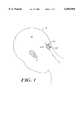
- FIG. 1is a perspective view of an implanted shunt valve and a device for obtaining information from the shunt valve in accordance with the present invention
- FIG. 2is a perspective view of the device of FIG. 1;
- FIG. 3is a perspective view of the shunt valve of FIG. 1 shown without an exterior portion of the shunt valve;
- FIG. 4is a top view of the device of FIG. 1;
- FIG. 5is a side view of the device of FIG. 1;
- FIG. 5Ais a side view of an alternative embodiment of the device of FIG. 1;
- FIG. 6is a top view of another embodiment of a device in accordance with the present invention.
- FIG. 7is a side view of the device of FIG. 6;
- FIG. 8is a top view of the shunt valve of FIG. 3;
- FIG. 9is a cross-sectional view of the shunt valve of FIG. 3 along lines 9--9;
- FIG. 10is a top view of the device and shunt valve of FIG. 1 shown in a first position
- FIG. 11is a further top view of the device and shunt valve of FIG. 1 shown in a second position.
- FIGS. 1-3show a system 100 including a shunt valve 200 and a device 300 for determining a pressure setting of the shunt valve 200.
- the shunt valve 200is implanted under the scalp (not shown) of a patient 10 proximate the skull 12.
- the device 300is adapted for being externally mounted on the patient's head over the protrusion corresponding to the implanted shunt valve 200.
- the device 300includes a housing 302 having a geometry adapted for placement against the body of a patient. It is understood that the housing 302 can have a variety of configurations that allow the device 300 to be positioned in relation to an implanted apparatus.
- the housing 302includes opposed first and second side walls 304a,b and a top portion 306. The side walls 304 and the top portion 306 together form a channel 308 that is sized to accommodate a protrusion on a patient's scalp corresponding to the implanted shunt valve 200.
- a chamber 310Disposed within the top portion 306 of the housing is a chamber 310 (FIG. 5) in which a ferromagnetic indicator 312 is freely movable.
- the chamber 310can contain a fluid 314, such as a clear oil, that allows the ferromagnetic indicator 312 to freely move within the chamber 310.
- the ferromagnetic indicator 312can float on the fluid 314 or the fluid can facilitate movement of the ferromagnetic indicator by reducing frictional forces.
- a plurality of markings 316 indicative of a pressure setting of the implanted apparatuscan be affixed on the housing 302.
- the markings 316can also include a central marking 318 that can facilitate proper positioning of the device in relation to the implanted shunt valve.
- the housing 302can further include a magnifying element 320, such as a lens, that is effective to enhance a visual determination of the position of the relatively small ferromagnetic indicator 312. It is understood that the magnifying element 320 can be affixed to the device or it can be a separate component, such as a loupe type instrument.
- FIGS. 6-7show an alternative embodiment of the device 300' wherein the ferromagnetic indicator 312 is secured to the housing 302 at a pivot point 322.
- the ferromagnetic indicator 312is freely rotatable about the pivot point 322.
- a ferromagnetic material 324such as iron filings, is contained within first and second cavities 326a,b located in respective first and second wall portions 304a,b of the housing.
- the ferromagnetic material 324provides an indication of the relative alignment of the device 300' in relation to the shunt valve 200. That is, when the pivot point 322 is aligned with the ferromagnetic material 324 in the first and second cavities 326a,b, the device 300' is properly positioned in relation to the shunt valve 200.
- the ferromagnetic indicator 312then rotates about the pivot point 322 and points to one of the markings 316 on the housing.
- the shunt valve 200is typically implanted under the scalp in fluid communication with a ventricular catheter (not shown) located in the ventricles of the patient's brain.
- the shunt valve 200is effective to drain excess cerebrospinal fluid (CSF) to reduce elevated intracranial pressure.
- the shunt valve 200includes a stepping motor 202 that is actuable by means of an external programmer (see U.S. Pat. No. 4,772,257) to set a threshold pressure above which CSF flows through the shunt valve.
- the stepping motor 202includes a rotor 204 that is effective to rotate a cam 206 having a series of steps 208 formed thereon.
- a spring 210has a first end 210a in contact with the cam 206 and a second end 210b in biased contact with a spherical element 212.
- the particular step 208 on which the first end 210 of the spring restsdetermines the pressure applied to the spherical element 212 by the second end 210b of the spring.
- the shunt valve 200includes an indicator magnet 214 to allow the pressure setting of the shunt valve 200, e.g., the position of the cam 206, to be determined by the externally mountable device 300.
- the indicator magnet 214is secured within the shunt valve 200 in a fixed position relative to the cam 206 and/or rotor 204.
- the indicator magnet 214is secured to a top portion 216 of the cam such that the indicator magnet is coaxial with both the cam 206 and the rotor 204.
- the poles of the indicator magnet 214can be positioned to correspond to a predetermined pressure setting of the shunt valve.
- the device housing 302has a length LH (FIG. 4) that can range from about 10 millimeters to about 16 millimeters and a width WH that can range from about 8 millimeters to about 24 millimeters.
- the height HHcan vary from about 5 millimeters to about 10 millimeters.
- the chamber 310is generally centered between the sidewalls 304 with a diameter ranging from about 3 millimeters to about 7 millimeters.
- the depth DC (FIG. 5) of the chamber 310can vary from about 0.5 millimeter to about 1.5 millimeter and is preferably about 1.0 millimeter.
- the ferromagnetic indicator 312can be formed in a variety of geometries that enhance a visual determination of the position of the indicator.
- the ferromagnetic indicator 312is elongate or needle-shaped with a length of about 1.3 millimeter.
- the indicator magnet 214 housed within the shunt valve 200is, in an exemplary embodiment, circular with a diameter ranging from about 1.0 millimeter to about 1.2 millimeter with a thickness of about 0.3 millimeter.
- the indicator magnet 214generates a magnetic field having a strength in the range from about 100 Gauss to about 500 Gauss.
- the device 300is mounted upon the patient's scalp such that the protrusion corresponding to the shunt valve is generally within the channel 308 of the housing.
- An arrow 313indicates the direction of fluid flow for proper longitudinal orientation of the device. It is understood that CSF flows in a direction from the patient to the shunt valve.
- the device 300After initial placement on the scalp, the device 300 typically needs to be more accurately positioned with respect to the shunt valve 200. As shown in FIG. 10, for example, after initial placement of the device 300 over the scalp protrusion (not shown) the ferromagnetic indicator 312 is not aligned with the center marking 318. The position of the ferromagnetic indicator 312 is determined by the relative position of the indicator magnet 214 and the cam 206 which correspond to the pressure setting of the shunt valve 200. The device 300 should be manipulated until the ferromagnetic indicator 312 is within the center marking 318 on the housing, as shown in FIG. 11. After the device is properly positioned, the ferromagnetic indicator 312 points to one of the markings 316. Each of these markings corresponds to a particular pressure setting of the shunt valve 200.
- ferromagneticrefers to a property exhibited by certain metals, alloys, and compounds characterized by an attraction to a magnetized body.
- the ferromagnetic indicatormay be comprised of a ferrite steel in one embodiment.
- the ferromagnetic indicatorcan be a composite material containing ferromagnetic and non-ferromagnetic materials.
Landscapes
- Health & Medical Sciences (AREA)
- Engineering & Computer Science (AREA)
- Biomedical Technology (AREA)
- Hematology (AREA)
- Animal Behavior & Ethology (AREA)
- Otolaryngology (AREA)
- Anesthesiology (AREA)
- Heart & Thoracic Surgery (AREA)
- Neurology (AREA)
- Life Sciences & Earth Sciences (AREA)
- Ophthalmology & Optometry (AREA)
- General Health & Medical Sciences (AREA)
- Public Health (AREA)
- Veterinary Medicine (AREA)
- External Artificial Organs (AREA)
- Measuring Pulse, Heart Rate, Blood Pressure Or Blood Flow (AREA)
- Prostheses (AREA)
- Measuring And Recording Apparatus For Diagnosis (AREA)
Abstract
Description
Claims (13)
Priority Applications (5)
| Application Number | Priority Date | Filing Date | Title |
|---|---|---|---|
| US09/062,334US6050969A (en) | 1998-04-17 | 1998-04-17 | Pressure indicator |
| EP99913941AEP1071489A1 (en) | 1998-04-17 | 1999-03-17 | Pressure indicator |
| PCT/US1999/005878WO1999053990A1 (en) | 1998-04-17 | 1999-03-17 | Pressure indicator |
| JP2000544390AJP4306964B2 (en) | 1998-04-17 | 1999-03-17 | Pressure indicator |
| AU31902/99AAU3190299A (en) | 1998-04-17 | 1999-03-17 | Pressure indicator |
Applications Claiming Priority (1)
| Application Number | Priority Date | Filing Date | Title |
|---|---|---|---|
| US09/062,334US6050969A (en) | 1998-04-17 | 1998-04-17 | Pressure indicator |
Publications (1)
| Publication Number | Publication Date |
|---|---|
| US6050969Atrue US6050969A (en) | 2000-04-18 |
Family
ID=22041795
Family Applications (1)
| Application Number | Title | Priority Date | Filing Date |
|---|---|---|---|
| US09/062,334Expired - LifetimeUS6050969A (en) | 1998-04-17 | 1998-04-17 | Pressure indicator |
Country Status (5)
| Country | Link |
|---|---|
| US (1) | US6050969A (en) |
| EP (1) | EP1071489A1 (en) |
| JP (1) | JP4306964B2 (en) |
| AU (1) | AU3190299A (en) |
| WO (1) | WO1999053990A1 (en) |
Cited By (27)
| Publication number | Priority date | Publication date | Assignee | Title |
|---|---|---|---|---|
| US6383160B1 (en)* | 1999-04-29 | 2002-05-07 | Children's Medical Center Corporation | Variable anti-siphon valve apparatus and method |
| US6439538B1 (en)* | 1999-10-04 | 2002-08-27 | Seiko Instruments Inc. | Pressure variable valve apparatus and set pressure detecting apparatus of the valve apparatus |
| US6474360B1 (en)* | 1999-06-15 | 2002-11-05 | Seiko Instruments Inc. | Variable pressure valve apparatus |
| US6485449B2 (en)* | 1999-12-20 | 2002-11-26 | Seiko Instruments Inc. | Pressure-variable valve device and set-pressure adjusting device for the valve device |
| EP1243826A3 (en)* | 2001-03-21 | 2003-05-21 | Seiko Instruments Inc. | Pressure-variable valve device and set-pressure adjusting device for the valve device |
| US6585677B2 (en) | 2000-08-30 | 2003-07-01 | John A. Cowan, Jr. | Shunt |
| US20030216710A1 (en)* | 2002-03-26 | 2003-11-20 | Hurt Robert F. | Catheter |
| US6684904B2 (en)* | 1999-06-15 | 2004-02-03 | Seiko Instruments Inc. | Variable pressure valve apparatus |
| US6702249B2 (en)* | 2001-03-19 | 2004-03-09 | Seiko Instruments Inc. | Pressure-variable valve device and set-pressure adjusting device for the valve device |
| EP1457231A1 (en)* | 2003-03-12 | 2004-09-15 | Integra Neurosciences Implants (France) SA | Implantable valve for the treatment of hydrocephalus |
| US20050187509A1 (en)* | 2004-02-25 | 2005-08-25 | Wolf Erich W. | Transcutaneous telemetry of cerebrospinal fluid shunt programmable-valve pressure using near-infrared (NIR) light |
| US20060074371A1 (en)* | 2004-09-30 | 2006-04-06 | Codman & Shurtleff, Inc. | High pressure range hydrocephalus valve system |
| US20070038171A1 (en)* | 2005-07-25 | 2007-02-15 | Mayer Peter L | Shunt system |
| US20090204054A1 (en)* | 2004-02-25 | 2009-08-13 | Wolf Ii Erich W | Transcutaneous telemetry of cerebrospinal fluid shunt programmable-valve pressure using near-infrared (nir) light |
| US20100199506A1 (en)* | 2009-02-12 | 2010-08-12 | Christophe Moureaux | Device for mechanically locating and reading the setting of an adjustable valve |
| US20110066098A1 (en)* | 2007-11-23 | 2011-03-17 | Ecole Polytechnique Federale De Lausanne (Epfl) | Non-invasively adjustable drainage device |
| US20110112460A1 (en)* | 2009-11-09 | 2011-05-12 | Medtronic Xomed, Inc. | Adjustable valve setting with motor control |
| US20120046595A1 (en)* | 2010-08-17 | 2012-02-23 | Codman & Shurtleff, Inc. | Implantable adjustable valve |
| US20140121586A1 (en)* | 1999-03-17 | 2014-05-01 | Medtronic, Inc. | Tool For Adjusting An Implantable Adjustable Fluid Flow Control Valve |
| US9126010B2 (en) | 2013-03-14 | 2015-09-08 | Medtronic Xomed, Inc. | Device and method for finding the center and reading the setting of an implantable medical device |
| US9149615B2 (en) | 2010-08-17 | 2015-10-06 | DePuy Synthes Products, Inc. | Method and tools for implanted device |
| US9295826B2 (en) | 2012-06-21 | 2016-03-29 | Medtronic Xomed, Inc. | Fluid flow control devices, rotors and magnets with increased resistance to inadvertent setting change and improved accessory tool coupling |
| US9694166B2 (en) | 2002-03-26 | 2017-07-04 | Medtronics Ps Medical, Inc. | Method of draining cerebrospinal fluid |
| WO2018031936A1 (en)* | 2016-08-12 | 2018-02-15 | Hakim Carlos | Externally programmable magnetic valve assembly and controller |
| US10183143B2 (en) | 2013-03-15 | 2019-01-22 | Bitol Designs, Llc | Occlusion resistant catheter and method of use |
| US10406331B2 (en)* | 2016-11-14 | 2019-09-10 | Integra Lifesciences Switzerland Sàrl | Device and method to locate and read an implanted device using ultrasound |
| US12420075B2 (en) | 2016-08-12 | 2025-09-23 | Ceredyn Biotechnology Llc | Externally programable magnetic valve assembly and controller |
Families Citing this family (12)
| Publication number | Priority date | Publication date | Assignee | Title |
|---|---|---|---|---|
| US7585280B2 (en) | 2004-12-29 | 2009-09-08 | Codman & Shurtleff, Inc. | System and method for measuring the pressure of a fluid system within a patient |
| WO2009034410A1 (en)* | 2007-09-10 | 2009-03-19 | Sophysa | Device and method for mechanically locating and reading the setting of an adjustable valve |
| US7842004B2 (en)* | 2007-10-31 | 2010-11-30 | Codman & Shurtleff, Inc. | Wireless pressure setting indicator |
| US8480612B2 (en) | 2007-10-31 | 2013-07-09 | DePuy Synthes Products, LLC | Wireless shunts with storage |
| US8454524B2 (en) | 2007-10-31 | 2013-06-04 | DePuy Synthes Products, LLC | Wireless flow sensor |
| US9204812B2 (en) | 2007-10-31 | 2015-12-08 | DePuy Synthes Products, LLC | Wireless pressure sensing shunts |
| JP5330851B2 (en)* | 2009-02-12 | 2013-10-30 | ソフィサ | Device for mechanically positioning and reading the setpoint of the adjustable valve |
| US8088091B2 (en) | 2009-03-09 | 2012-01-03 | New Jersey Institute Of Technology | No clog shunt using a compact fluid drag path |
| US8038641B2 (en)* | 2009-03-31 | 2011-10-18 | Codman & Shurtleff, Inc. | Tools and methods for programming an implantable valve |
| US10322267B2 (en) | 2013-03-15 | 2019-06-18 | Carlos A. Hakim | Externally programmable valve assembly |
| US9872972B2 (en)* | 2014-09-04 | 2018-01-23 | Integra LifeSciences Switzerland Sarl | Methods and devices for locating and adjusting an implantable valve |
| US10226193B2 (en) | 2015-03-31 | 2019-03-12 | Medtronic Ps Medical, Inc. | Wireless pressure measurement and monitoring for shunts |
Citations (18)
| Publication number | Priority date | Publication date | Assignee | Title |
|---|---|---|---|---|
| US3423672A (en)* | 1967-05-08 | 1969-01-21 | Raymond F Stockton | Terrestrial magnetism responsive device including fluid supported indicating means for investigating subsurface characteristics of the earth |
| US4146029A (en)* | 1974-04-23 | 1979-03-27 | Ellinwood Jr Everett H | Self-powered implanted programmable medication system and method |
| US4204547A (en)* | 1978-11-13 | 1980-05-27 | Allocca John A | Method and apparatus for noninvasive monitoring of intracranial pressure |
| US4360007A (en)* | 1980-08-05 | 1982-11-23 | Yeda Research And Development Co., Ltd. | Remote controlled magnetic actuator particularly for an implantable device like a valve |
| US4438568A (en)* | 1980-03-13 | 1984-03-27 | The Brunton Company | Recreational compass |
| US4443214A (en)* | 1981-03-18 | 1984-04-17 | Society Dite: Sophysa | Valve for the treatment of hydrocephalus |
| US4540400A (en)* | 1983-02-17 | 1985-09-10 | Cordis Corporation | Non-invasively adjustable valve |
| US4551128A (en)* | 1983-05-11 | 1985-11-05 | Salomon Hakim | Cerebrospinal fluid shunt valve |
| US4595390A (en)* | 1983-07-21 | 1986-06-17 | Salomon Hakim | Magnetically-adjustable cerebrospinal fluid shunt valve |
| US4608992A (en)* | 1983-08-18 | 1986-09-02 | Salomon Hakim | External magnetic detection of physiopathological and other parameters |
| US4615691A (en)* | 1983-12-08 | 1986-10-07 | Salomon Hakim | Surgically-implantable stepping motor |
| US4676772A (en)* | 1985-12-23 | 1987-06-30 | Cordis Corporation | Adjustable implantable valve having non-invasive position indicator |
| US4700490A (en)* | 1985-01-16 | 1987-10-20 | The Brunton Company | Compass |
| US4772257A (en)* | 1983-12-08 | 1988-09-20 | Salomon Hakim | External programmer for magnetically-adjustable cerebrospinal fluid shunt valve |
| US5146687A (en)* | 1991-02-25 | 1992-09-15 | Bjorn Kjellstrom | Compass |
| US5187871A (en)* | 1992-01-27 | 1993-02-23 | Mcdermott Damien | Underwater navigation device |
| US5637083A (en)* | 1996-01-19 | 1997-06-10 | Pudenz-Schulte Medical Research Corporation | Implantable adjustable fluid flow control valve |
| US5643194A (en)* | 1994-06-24 | 1997-07-01 | Sophysa | Subcutaneous valve and device for externally setting it |
Family Cites Families (3)
| Publication number | Priority date | Publication date | Assignee | Title |
|---|---|---|---|---|
| US2836144A (en)* | 1957-06-21 | 1958-05-27 | Leta S Taylor | Gauge head |
| US4016827A (en)* | 1975-09-12 | 1977-04-12 | Lawrence Jr James F | Magnetically coupled indicator means for control setting |
| DE2626215C3 (en)* | 1976-06-11 | 1979-03-01 | Messerschmitt-Boelkow-Blohm Gmbh, 8000 Muenchen | Drainage device for draining excess fluid from the cerebral cavities |
- 1998
- 1998-04-17USUS09/062,334patent/US6050969A/ennot_activeExpired - Lifetime
- 1999
- 1999-03-17EPEP99913941Apatent/EP1071489A1/ennot_activeWithdrawn
- 1999-03-17AUAU31902/99Apatent/AU3190299A/ennot_activeAbandoned
- 1999-03-17JPJP2000544390Apatent/JP4306964B2/ennot_activeExpired - Fee Related
- 1999-03-17WOPCT/US1999/005878patent/WO1999053990A1/ennot_activeApplication Discontinuation
Patent Citations (18)
| Publication number | Priority date | Publication date | Assignee | Title |
|---|---|---|---|---|
| US3423672A (en)* | 1967-05-08 | 1969-01-21 | Raymond F Stockton | Terrestrial magnetism responsive device including fluid supported indicating means for investigating subsurface characteristics of the earth |
| US4146029A (en)* | 1974-04-23 | 1979-03-27 | Ellinwood Jr Everett H | Self-powered implanted programmable medication system and method |
| US4204547A (en)* | 1978-11-13 | 1980-05-27 | Allocca John A | Method and apparatus for noninvasive monitoring of intracranial pressure |
| US4438568A (en)* | 1980-03-13 | 1984-03-27 | The Brunton Company | Recreational compass |
| US4360007A (en)* | 1980-08-05 | 1982-11-23 | Yeda Research And Development Co., Ltd. | Remote controlled magnetic actuator particularly for an implantable device like a valve |
| US4443214A (en)* | 1981-03-18 | 1984-04-17 | Society Dite: Sophysa | Valve for the treatment of hydrocephalus |
| US4540400A (en)* | 1983-02-17 | 1985-09-10 | Cordis Corporation | Non-invasively adjustable valve |
| US4551128A (en)* | 1983-05-11 | 1985-11-05 | Salomon Hakim | Cerebrospinal fluid shunt valve |
| US4595390A (en)* | 1983-07-21 | 1986-06-17 | Salomon Hakim | Magnetically-adjustable cerebrospinal fluid shunt valve |
| US4608992A (en)* | 1983-08-18 | 1986-09-02 | Salomon Hakim | External magnetic detection of physiopathological and other parameters |
| US4615691A (en)* | 1983-12-08 | 1986-10-07 | Salomon Hakim | Surgically-implantable stepping motor |
| US4772257A (en)* | 1983-12-08 | 1988-09-20 | Salomon Hakim | External programmer for magnetically-adjustable cerebrospinal fluid shunt valve |
| US4700490A (en)* | 1985-01-16 | 1987-10-20 | The Brunton Company | Compass |
| US4676772A (en)* | 1985-12-23 | 1987-06-30 | Cordis Corporation | Adjustable implantable valve having non-invasive position indicator |
| US5146687A (en)* | 1991-02-25 | 1992-09-15 | Bjorn Kjellstrom | Compass |
| US5187871A (en)* | 1992-01-27 | 1993-02-23 | Mcdermott Damien | Underwater navigation device |
| US5643194A (en)* | 1994-06-24 | 1997-07-01 | Sophysa | Subcutaneous valve and device for externally setting it |
| US5637083A (en)* | 1996-01-19 | 1997-06-10 | Pudenz-Schulte Medical Research Corporation | Implantable adjustable fluid flow control valve |
Non-Patent Citations (4)
| Title |
|---|
| Advertisement material for Medtronic, STRATA Adjustable Delta Valve.* |
| Advertisement material for Medtronic, STRATA™ Adjustable Delta Valve. |
| Article Entitled, "The SOPHY Programmable Pressure Valve Model SU8," appears to correspond to U.S. Patent No. 4,443,214. Horological Technology to benefit the Neurosurgeon. |
| Article Entitled, The SOPHY Programmable Pressure Valve Model SU8, appears to correspond to U.S. Patent No. 4,443,214. Horological Technology to benefit the Neurosurgeon.* |
Cited By (57)
| Publication number | Priority date | Publication date | Assignee | Title |
|---|---|---|---|---|
| USD946143S1 (en) | 1999-03-17 | 2022-03-15 | Medtronic, Inc. | Tool for adjusting an implantable adjustable fluid flow control valve |
| USD1054554S1 (en) | 1999-03-17 | 2024-12-17 | Medtronic, Inc. | Tool for adjusting an implantable adjustable fluid flow control valve |
| USD961071S1 (en) | 1999-03-17 | 2022-08-16 | Medtronic, Inc. | Tool for adjusting an implantable adjustable fluid flow control valve |
| US20140121586A1 (en)* | 1999-03-17 | 2014-05-01 | Medtronic, Inc. | Tool For Adjusting An Implantable Adjustable Fluid Flow Control Valve |
| USD928313S1 (en) | 1999-03-17 | 2021-08-17 | Medtronic, Inc. | Tool for adjusting an implantable adjustable fluid flow control valve |
| USD945608S1 (en) | 1999-03-17 | 2022-03-08 | Medtronic, Inc. | Tool for adjusting an implantable adjustable fluid flow control valve |
| USD922572S1 (en) | 1999-03-17 | 2021-06-15 | Medtronic, Inc. | Tool for adjusting an implantable adjustable fluid flow control valve |
| US9364646B2 (en)* | 1999-03-17 | 2016-06-14 | Medtronic, Inc. | Tool for adjusting an implantable adjustable fluid flow control valve |
| US6383160B1 (en)* | 1999-04-29 | 2002-05-07 | Children's Medical Center Corporation | Variable anti-siphon valve apparatus and method |
| US6474360B1 (en)* | 1999-06-15 | 2002-11-05 | Seiko Instruments Inc. | Variable pressure valve apparatus |
| US6684904B2 (en)* | 1999-06-15 | 2004-02-03 | Seiko Instruments Inc. | Variable pressure valve apparatus |
| US6439538B1 (en)* | 1999-10-04 | 2002-08-27 | Seiko Instruments Inc. | Pressure variable valve apparatus and set pressure detecting apparatus of the valve apparatus |
| US6485449B2 (en)* | 1999-12-20 | 2002-11-26 | Seiko Instruments Inc. | Pressure-variable valve device and set-pressure adjusting device for the valve device |
| US6585677B2 (en) | 2000-08-30 | 2003-07-01 | John A. Cowan, Jr. | Shunt |
| US6932787B2 (en) | 2000-08-30 | 2005-08-23 | John A. Cowan | Shunt |
| US20040030278A1 (en)* | 2000-08-30 | 2004-02-12 | Cowan John A. | Shunt |
| US6702249B2 (en)* | 2001-03-19 | 2004-03-09 | Seiko Instruments Inc. | Pressure-variable valve device and set-pressure adjusting device for the valve device |
| EP1243826A3 (en)* | 2001-03-21 | 2003-05-21 | Seiko Instruments Inc. | Pressure-variable valve device and set-pressure adjusting device for the valve device |
| US9694166B2 (en) | 2002-03-26 | 2017-07-04 | Medtronics Ps Medical, Inc. | Method of draining cerebrospinal fluid |
| US20030216710A1 (en)* | 2002-03-26 | 2003-11-20 | Hurt Robert F. | Catheter |
| EP1457231A1 (en)* | 2003-03-12 | 2004-09-15 | Integra Neurosciences Implants (France) SA | Implantable valve for the treatment of hydrocephalus |
| US20040236264A1 (en)* | 2003-03-12 | 2004-11-25 | Alain Lecuyer | Implantable valve for the treatment of hydrocephalus |
| FR2852252A1 (en)* | 2003-03-12 | 2004-09-17 | Integra Neurosciences Implants | IMPLANTABLE VALVE FOR THE TREATMENT OF HYDROCEPHALIA |
| US20090204054A1 (en)* | 2004-02-25 | 2009-08-13 | Wolf Ii Erich W | Transcutaneous telemetry of cerebrospinal fluid shunt programmable-valve pressure using near-infrared (nir) light |
| US7485105B2 (en) | 2004-02-25 | 2009-02-03 | Wolf Erich W | Transcutaneous telemetry of cerebrospinal fluid shunt programmable-valve pressure using near-infrared (NIR) light |
| US8057422B2 (en) | 2004-02-25 | 2011-11-15 | Wolf Ii Erich W | Transcutaneous telemetry of cerebrospinal fluid shunt programmable-valve pressure using near-infrared (NIR) light |
| US20050187509A1 (en)* | 2004-02-25 | 2005-08-25 | Wolf Erich W. | Transcutaneous telemetry of cerebrospinal fluid shunt programmable-valve pressure using near-infrared (NIR) light |
| US7559912B2 (en) | 2004-09-30 | 2009-07-14 | Codman & Shurtleff, Inc. | High pressure range hydrocephalus valve system |
| US20100010415A1 (en)* | 2004-09-30 | 2010-01-14 | Codman & Shurtleff, Inc. | High pressure range hydrocephalus valve system |
| US20060074371A1 (en)* | 2004-09-30 | 2006-04-06 | Codman & Shurtleff, Inc. | High pressure range hydrocephalus valve system |
| US8088092B2 (en) | 2004-09-30 | 2012-01-03 | Codman & Shurtleff, Inc. | High pressure range hydrocephalus valve system |
| US20070038171A1 (en)* | 2005-07-25 | 2007-02-15 | Mayer Peter L | Shunt system |
| US20160287439A1 (en)* | 2007-11-23 | 2016-10-06 | Ecole Polytechnique Federale De Lausanne (Epfl) | Non-invasively adjustable drainage device |
| US9375347B2 (en)* | 2007-11-23 | 2016-06-28 | Ecole Polytechnique Federale De Lausanne (Epfl) | Non-invasively adjustable drainage device |
| US20110066098A1 (en)* | 2007-11-23 | 2011-03-17 | Ecole Polytechnique Federale De Lausanne (Epfl) | Non-invasively adjustable drainage device |
| US20100199506A1 (en)* | 2009-02-12 | 2010-08-12 | Christophe Moureaux | Device for mechanically locating and reading the setting of an adjustable valve |
| US7921571B2 (en)* | 2009-02-12 | 2011-04-12 | Sophysa | Device for mechanically locating and reading the setting of an adjustable valve |
| US8241240B2 (en)* | 2009-11-09 | 2012-08-14 | Medtronic Xomed, Inc. | Adjustable valve setting with motor control |
| US8753331B2 (en) | 2009-11-09 | 2014-06-17 | Medtronic Xomed, Inc. | Adjustable valve setting with motor control |
| US20110112460A1 (en)* | 2009-11-09 | 2011-05-12 | Medtronic Xomed, Inc. | Adjustable valve setting with motor control |
| US20120046595A1 (en)* | 2010-08-17 | 2012-02-23 | Codman & Shurtleff, Inc. | Implantable adjustable valve |
| US9149615B2 (en) | 2010-08-17 | 2015-10-06 | DePuy Synthes Products, Inc. | Method and tools for implanted device |
| US10092734B2 (en) | 2010-08-17 | 2018-10-09 | Integra LifeSciences Switzerland Sarl | Method and tools for implanted device |
| US8322365B2 (en)* | 2010-08-17 | 2012-12-04 | Codman & Shurtleff, Inc. | Implantable adjustable valve |
| US8617142B2 (en) | 2010-08-17 | 2013-12-31 | DePuy Synthes Products, LLC | Implantable adjustable valve |
| US10369335B2 (en)* | 2012-06-21 | 2019-08-06 | Medtronic Xomed, Inc. | Fluid flow control devices, rotors and magnets with increased resistance to inadvertent setting change and improved accessory tool coupling |
| US9295826B2 (en) | 2012-06-21 | 2016-03-29 | Medtronic Xomed, Inc. | Fluid flow control devices, rotors and magnets with increased resistance to inadvertent setting change and improved accessory tool coupling |
| US11167117B2 (en)* | 2012-06-21 | 2021-11-09 | Medtronic Xomed, Inc. | Fluid flow control devices, rotors and magnets with increased resistance to inadvertent setting change and improved accessory tool coupling |
| US9427559B2 (en) | 2013-03-14 | 2016-08-30 | Medtronic Xomed, Inc. | Device and method for finding the center and reading the setting of an implantable medical device |
| US9126010B2 (en) | 2013-03-14 | 2015-09-08 | Medtronic Xomed, Inc. | Device and method for finding the center and reading the setting of an implantable medical device |
| US10183143B2 (en) | 2013-03-15 | 2019-01-22 | Bitol Designs, Llc | Occlusion resistant catheter and method of use |
| US10864363B2 (en) | 2016-08-12 | 2020-12-15 | Carlos A. Hakim | Externally programable magnetic valve assembly and controller |
| WO2018031936A1 (en)* | 2016-08-12 | 2018-02-15 | Hakim Carlos | Externally programmable magnetic valve assembly and controller |
| CN109803606A (en)* | 2016-08-12 | 2019-05-24 | 卡洛斯.A.哈金 | Externally programmable solenoid valve assemblies and controllers |
| US12420075B2 (en) | 2016-08-12 | 2025-09-23 | Ceredyn Biotechnology Llc | Externally programable magnetic valve assembly and controller |
| US12434043B2 (en) | 2016-08-12 | 2025-10-07 | Ceredyn Biotechnology Llc | Externally programable magnetic valve assembly and controller |
| US10406331B2 (en)* | 2016-11-14 | 2019-09-10 | Integra Lifesciences Switzerland Sàrl | Device and method to locate and read an implanted device using ultrasound |
Also Published As
| Publication number | Publication date |
|---|---|
| AU3190299A (en) | 1999-11-08 |
| JP2002512095A (en) | 2002-04-23 |
| EP1071489A1 (en) | 2001-01-31 |
| JP4306964B2 (en) | 2009-08-05 |
| WO1999053990A1 (en) | 1999-10-28 |
Similar Documents
| Publication | Publication Date | Title |
|---|---|---|
| US6050969A (en) | Pressure indicator | |
| US9427559B2 (en) | Device and method for finding the center and reading the setting of an implantable medical device | |
| US7422566B2 (en) | Method of treating a patient with hydrocephalus and apparatus therefor | |
| AU2006200951B2 (en) | Pressure sensing devices | |
| EP2420284B1 (en) | Implantable adjustable valve | |
| JP5474633B2 (en) | Tools and methods for programming implantable valves | |
| EP3263172B1 (en) | Device to control magnetic rotor of a programmable hydrocephalus valve | |
| US6045530A (en) | Adjustable angle catheter | |
| US7559912B2 (en) | High pressure range hydrocephalus valve system | |
| AU2018241070B2 (en) | An Implantable Bodily Fluid Drainage Valve with Magnetic Field Resistance Engagement Confirmation | |
| US10406331B2 (en) | Device and method to locate and read an implanted device using ultrasound | |
| AU2018241068B2 (en) | Electronic Toolset to Locate, Read, Adjust, and Confirm Adjustment in an Implantable Bodily Fluid Drainage System Without Recalibrating Following Adjustment | |
| JP7226887B2 (en) | An electronic toolset for locating, reading, adjusting, and confirming adjustments of an implantable fluid drainage system without post-adjustment recalibration | |
| CA3019544C (en) | An implantable bodily fluid drainage valve with magnetic field resistance engagement confirmation | |
| EP3632496B1 (en) | An implantable bodily fluid drainage valve with magnetic field resistance engagement confirmation method | |
| EP3632498A1 (en) | Electronic toolset to locate, read, adjust, and confirm adjustment in an implantable bodily fluid drainage system without recalibrating following adjustment | |
| CA3019407A1 (en) | Electronic toolset to locate, read, adjust, and confirm adjustment in an implantable bodily fluid drainage system without recalibrating following adjustment |
Legal Events
| Date | Code | Title | Description |
|---|---|---|---|
| AS | Assignment | Owner name:JOHNSON & JOHNSON PROFESSIONAL, INC., MASSACHUSETT Free format text:ASSIGNMENT OF ASSIGNORS INTEREST;ASSIGNOR:KRAUS, ROBERT G.;REEL/FRAME:009127/0449 Effective date:19980416 | |
| STCF | Information on status: patent grant | Free format text:PATENTED CASE | |
| AS | Assignment | Owner name:DEPUY ORTHOPAEDICS, INC., NEW JERSEY Free format text:MERGER;ASSIGNOR:CASES TO BE RECORDED IN THE NAME OF DEPUY ORTHOPAEDICS, INC.;REEL/FRAME:010725/0402 Effective date:19990703 | |
| FEPP | Fee payment procedure | Free format text:PAYOR NUMBER ASSIGNED (ORIGINAL EVENT CODE: ASPN); ENTITY STATUS OF PATENT OWNER: LARGE ENTITY | |
| FPAY | Fee payment | Year of fee payment:4 | |
| FPAY | Fee payment | Year of fee payment:8 | |
| FPAY | Fee payment | Year of fee payment:12 | |
| AS | Assignment | Owner name:DEPUY SYNTHES PRODUCTS, INC., MASSACHUSETTS Free format text:ASSIGNMENT OF ASSIGNORS INTEREST;ASSIGNOR:DEPUY ORTHOPAEDICS, INC.;REEL/FRAME:046237/0671 Effective date:20180503 Owner name:INTEGRA LIFESCIENCES SWITZERLAND SARL, SWITZERLAND Free format text:ASSIGNMENT OF ASSIGNORS INTEREST;ASSIGNOR:DEPUY SYNTHES PRODUCTS, INC.;REEL/FRAME:046237/0800 Effective date:20180606 |