US6050842A - Electrical connector with paired terminals - Google Patents
Electrical connector with paired terminalsDownload PDFInfo
- Publication number
- US6050842A US6050842AUS08/723,230US72323096AUS6050842AUS 6050842 AUS6050842 AUS 6050842AUS 72323096 AUS72323096 AUS 72323096AUS 6050842 AUS6050842 AUS 6050842A
- Authority
- US
- United States
- Prior art keywords
- wire
- terminal
- terminals
- housing
- pairs
- Prior art date
- Legal status (The legal status is an assumption and is not a legal conclusion. Google has not performed a legal analysis and makes no representation as to the accuracy of the status listed.)
- Expired - Lifetime
Links
Images


Classifications
- H—ELECTRICITY
- H01—ELECTRIC ELEMENTS
- H01R—ELECTRICALLY-CONDUCTIVE CONNECTIONS; STRUCTURAL ASSOCIATIONS OF A PLURALITY OF MUTUALLY-INSULATED ELECTRICAL CONNECTING ELEMENTS; COUPLING DEVICES; CURRENT COLLECTORS
- H01R4/00—Electrically-conductive connections between two or more conductive members in direct contact, i.e. touching one another; Means for effecting or maintaining such contact; Electrically-conductive connections having two or more spaced connecting locations for conductors and using contact members penetrating insulation
- H01R4/24—Connections using contact members penetrating or cutting insulation or cable strands
- H01R4/2416—Connections using contact members penetrating or cutting insulation or cable strands the contact members having insulation-cutting edges, e.g. of tuning fork type
- H01R4/242—Connections using contact members penetrating or cutting insulation or cable strands the contact members having insulation-cutting edges, e.g. of tuning fork type the contact members being plates having a single slot
- H01R4/2425—Flat plates, e.g. multi-layered flat plates
- H01R4/2429—Flat plates, e.g. multi-layered flat plates mounted in an insulating base
- H—ELECTRICITY
- H01—ELECTRIC ELEMENTS
- H01R—ELECTRICALLY-CONDUCTIVE CONNECTIONS; STRUCTURAL ASSOCIATIONS OF A PLURALITY OF MUTUALLY-INSULATED ELECTRICAL CONNECTING ELEMENTS; COUPLING DEVICES; CURRENT COLLECTORS
- H01R12/00—Structural associations of a plurality of mutually-insulated electrical connecting elements, specially adapted for printed circuits, e.g. printed circuit boards [PCB], flat or ribbon cables, or like generally planar structures, e.g. terminal strips, terminal blocks; Coupling devices specially adapted for printed circuits, flat or ribbon cables, or like generally planar structures; Terminals specially adapted for contact with, or insertion into, printed circuits, flat or ribbon cables, or like generally planar structures
- H01R12/50—Fixed connections
- H01R12/51—Fixed connections for rigid printed circuits or like structures
- H01R12/515—Terminal blocks providing connections to wires or cables
- H—ELECTRICITY
- H01—ELECTRIC ELEMENTS
- H01R—ELECTRICALLY-CONDUCTIVE CONNECTIONS; STRUCTURAL ASSOCIATIONS OF A PLURALITY OF MUTUALLY-INSULATED ELECTRICAL CONNECTING ELEMENTS; COUPLING DEVICES; CURRENT COLLECTORS
- H01R13/00—Details of coupling devices of the kinds covered by groups H01R12/70 or H01R24/00 - H01R33/00
- H01R13/646—Details of coupling devices of the kinds covered by groups H01R12/70 or H01R24/00 - H01R33/00 specially adapted for high-frequency, e.g. structures providing an impedance match or phase match
- H01R13/6461—Means for preventing cross-talk
- H—ELECTRICITY
- H01—ELECTRIC ELEMENTS
- H01R—ELECTRICALLY-CONDUCTIVE CONNECTIONS; STRUCTURAL ASSOCIATIONS OF A PLURALITY OF MUTUALLY-INSULATED ELECTRICAL CONNECTING ELEMENTS; COUPLING DEVICES; CURRENT COLLECTORS
- H01R13/00—Details of coupling devices of the kinds covered by groups H01R12/70 or H01R24/00 - H01R33/00
- H01R13/646—Details of coupling devices of the kinds covered by groups H01R12/70 or H01R24/00 - H01R33/00 specially adapted for high-frequency, e.g. structures providing an impedance match or phase match
- H01R13/6473—Impedance matching
- H01R13/6477—Impedance matching by variation of dielectric properties
- Y—GENERAL TAGGING OF NEW TECHNOLOGICAL DEVELOPMENTS; GENERAL TAGGING OF CROSS-SECTIONAL TECHNOLOGIES SPANNING OVER SEVERAL SECTIONS OF THE IPC; TECHNICAL SUBJECTS COVERED BY FORMER USPC CROSS-REFERENCE ART COLLECTIONS [XRACs] AND DIGESTS
- Y10—TECHNICAL SUBJECTS COVERED BY FORMER USPC
- Y10S—TECHNICAL SUBJECTS COVERED BY FORMER USPC CROSS-REFERENCE ART COLLECTIONS [XRACs] AND DIGESTS
- Y10S439/00—Electrical connectors
- Y10S439/941—Crosstalk suppression
Definitions
- This inventionis related to an electrical connector that is used to terminate twisted pair wires.
- This inventionis also related to electrical connectors that employ slotted beam or insulation displacement contacts or terminals to establish an electrical connector with insulated wires. More particularly, this invention is also related to electrical connectors that can be used to improve inductive and capacitive electrical coupling between individual wires in a twisted pair and to reduce crosstalk between adjacent twisted pairs for higher frequency transmission, such as 100 Mhz signals.
- FIG. 1A conventional 110 style electrical connector used to terminate twisted pair telecommunications cables is shown in FIG. 1. These connectors 110 employ slotted beam or insulation displacement contact terminals 150.
- the connector shown in FIG. 1is a four position connector that is used to terminate tip and ring wires in a two pair cable to a printed circuit board using compliant pin sections 156.
- the four terminals 150are positioned side by side with the planar slotted beam portions 152 of the four terminals located in the same plane. Terminals 150 are received in cavities 136 in an insulated housing 112 that extend into tapered divider walls 124, center walls 120 and side walls 122 located on the top of the housing 112. These walls 120, 122, 124 define channels into which wires are inserted.
- Terminals 150are held in the housing 112 by tabs 162 struck from the sides of the terminal and by plastic inserted into the terminal opening left when the tabs 162 are formed.
- An electrical connector of similar construction that is used for splicing separate twisted pair cablesis disclosed in U.S. Pat. No. 5,409,404,
- Each of these prior art connectorsis primarily intended for use with conventional twisted pair cable of the type commonly used for telephone communications.
- Recently twisted pair cablehas been increasingly used for higher speed or higher frequency applications such as networked data communications.
- Standard twisted pair cableis not suitable for many of these applications because the transmission characteristics of standard twisted pair cable and twisted pair connectors are not satisfactory for these higher frequency applications. Therefore new standards for twisted pair cable suitable for higher frequencies have emerged.
- Category 5 twisted pair cableis one such cable. These cables are more tightly twisted to increase inductive and capacitive electrical coupling between individual wires forming each twisted pair. More stringent restrictions on crosstalk, and especially near end crosstalk (NEXT), have also been placed on these higher performance twisted pair cables.
- NXTnear end crosstalk
- the instant inventionis directed to an electrical connector configuration that addresses the shortcomings of standard electrical connectors, such as 110 style electrical connectors, when used with twisted pair cable intended for higher frequency applications.
- An object of this inventionis therefore to improve the coupling between individual wires of the same twisted pair at the electrical connector by maintaining the tighter twist of higher performance twisted pair cables closer to the connector.
- This inventionis also intended to reduce the crosstalk between adjacent twisted pairs at the connector by reducing the capacitance between adjacent terminals connected to adjacent wire pairs.
- this inventioncan be implemented in an electrical connector having the same cross sectional area as a standard 110 style connector and having the same contact footprint.
- Standard wire insertion tools used for 110 style connectorscan also be used with a connector embodying this invention.
- Another object of this inventionis to simplify the manner in which an electrical connector using compliant pins can be mounted on a printed circuit board.
- terminals in a connectorare inclined and offset relative to wire channels in a housing.
- Paired terminals used for each wire paircan be moved closer together into an overlapping relationship and separate terminal pairs can be separated to improve crosstalk performance
- the terminalscan also be made wider to improve terminal retention in the housing.
- an electrical connectorcomprising an insulating housing and slotted beam terminals for terminating individual wires in twisted wire pairs.
- the housingincludes wire channels and intersecting terminal cavities.
- the terminalsare positioned in the terminal cavities with a wire contact slot aligned with the corresponding wire channel.
- the maximum width of the terminalsis greater than the centerline spacing between adjacent wire channels that receive individual wires of the same wire pair.
- the terminals and the terminal cavitiesare inclined relative to the wire channels to achieve such spacing.
- the coupling between the wirescan be improved at the connector to improve the high frequency performance of the connector and the twisted wire pair.
- terminals for different wire pairscan be separated to reduce crosstalk between adjacent wire pairs
- Terminal retention in the housingcan therefore be improved. Improved terminal retention is especially important for connectors using compliant pins that must be inserted into plated through holes in a printed circuit board. Increased housing wall thickness limits breakage and damage to the connector.
- FIG. 1is a perspective view of a prior art electrical connector used with twisted wire pairs showing the terminals exploded from the insulated housing of the electrical connector.
- FIG. 2is a perspective view of the preferred embodiment of an electrical connector employing paired terminals and showing the insertion of individual wires of first and second twisted wire pairs in a wire cable.
- FIG. 3is a top plan view of the electrical connector shown in FIG. 2.
- FIG. 4is a bottom view of the electrical connector shown in FIGS. 2 and 3.
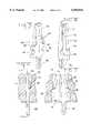
- FIG. 5is a perspective view of one embodiment of a terminal that could be used in the electrical connector of the type shown in FIGS. 2-4.
- FIG. 6is a partial section view showing the manner in which the terminal shown in FIG. 5 is secured to prevent the terminal from being pushed through the bottom of the connector housing.
- FIG. 7is a partial section view showing the manner in which the terminal shown in FIG. 5 is secured to prevent the terminal from being pushed out the top of the connector housing.
- FIG. 8is a perspective view showing an alternate embodiment of a terminal that could be used in and electrical connector of the type shown in FIGS. 2-4.
- FIG. 9is a perspective view of another alternate embodiment of the terminal.
- FIG. 10is a perspective view showing four terminals of the type shown in FIG. 9 showing the relative angular orientation and spacing between these terminals.
- FIG. 11is a perspective view of an insertion tool having two staggered insertion heads that could be used with an electrical connector of the type shown in FIGS. 2-4
- FIG. 12is a section view of the staggered insertion tool shown in FIG. 11.
- Electrical connector 10is a 110 style electrical connector that is used to connect a first twisted wire pair 2 and a second twisted wire pair 4 to a printed circuit board (not shown). Each twisted pair 2, 4 includes two wires 6 and 8 that are typically used in a balanced pair transmission line. Electrical connector 10 can be employed with conventional twisted pair cable of the type commonly used for conventional telecommunications. This connector 10 can also be used for higher speed applications since connector 10 is intended to improve the coupling between wires in the same twisted pair relative to conventional 110 style connectors and to reduce crosstalk between adjacent twisted pairs relative to conventional 110 style connectors. Specifically this connector 110 is intended to be used with higher performance twisted pair cable configurations, such as Category 5 twisted pair cables, that employ a tighter twist than conventional twisted pair cables.
- the connector 10is a four position connector in which four slotted beam or insulation displacement terminals 50, as shown in FIGS. 5-7, or alternate terminals 70, as shown in FIG. 8, are inserted into a molded insulated housing 12.
- Housing 12is a one piece structure having a base portion 14 with walls extending upwardly from an upper base surface 16.
- one central wall 20 and two side walls 22are separated by two tapered divider walls 24.
- the tapered divider walls 24are configured to act as splitters or dividers over which the individual wires 6, 8 forming one of the twisted wire pairs are separated.
- the wires 6, 8enter wire channels 34 formed on either side of one of the tapered divider walls 24.
- the channels 34are also formed by an adjacent central wall 20 or an adjacent side wall 22.
- Each tapered divider wall 24differs from the divider wall 124 in a conventional 110 style connector such as that shown in FIG. 1.
- Each tapered divider wall 24includes two mutually staggered sections 26, 28 that are respectively offset toward the front and rear or the housing 12 as viewed in FIG. 2.
- Each staggered sectionhas an inclined upper surface 30 and 32 respectively.
- the front inclined surface 30merges with the rear inclined surface 32 along a straight line apex at the top of the tapered divider wall.
- each tapered divider wall 24is described as having two sections 26, 28, it should be understood that each tapered divider wall is an integrally molded portion of the housing 12 and the staggered sections 26, 28 are really part of the same one-piece structure.
- These staggered sectionspermit the use of a standard, commonly available, single position insertion tool commonly employed to terminate conventional 110 style connecting blocks such as that shown in FIG. 1.
- the wire channels 34extend from the apex at the top of the tapered divider walls 24 to the upper surface 16 of the housing base 14.
- the four wire channels 34are mutually parallel and are perpendicular to the front and rear faces of the housing 12 between which the channels 34 extend
- Terminal cavities 36extend from the lower surface 18 of the housing base 14 through the upper surface 16 of the housing base 14 and extend upwardly in the tapered divider walls 24, the central wall 20 and the side walls 22 where they are manifested as opposed grooves extending into the corresponding wall from a corresponding wire channel 34.
- the terminal cavities 36are inclined relative to the wire channels 34.
- the angle of inclinationis between fifteen and thirty degrees. An inclination of twenty degrees is shown in the embodiment depicted herein.
- a central cavity 42extends upwardly from the lower surface 18 of the housing base 14 as shown in FIG. 4. This central cavity 42 is cored during molding of the housing 12 and extends upwardly into the central wall 20. In the preferred embodiment, the central cavity 42 terminates below the top surface of the central wall 20, which has a continuous upper surface as shown in FIGS. 2 and 3.
- Terminal 50that can be used in connector 10 is shown in FIGS. 5-7.
- This terminal 50is stamped and formed from a flat metal strip of a resilient metal.
- Terminal 50has a flat or planar slotted beam or insulation displacement contact section 52.
- a wire contact slot 54is formed between two opposed contact beams. A wire inserted laterally of its axis into the contact slot 54 will be engaged by the inward facing edges of the wire contact slot 54 and a gas tight mechanical and electrical connection will be established between the wire and the terminal 50.
- Terminal 50also includes a compliant pin 56 that can be inserted into a plated through hole in a printed circuit board. A press fit mechanical and electrical connection can then be established between the compliant pin 56 and the plated through hole. Insertion of the pin 56 into the hole will cause deflection of the two opposed arms forming the compliant pin 56 to establish a contact force between the pin and the plated through hole. As with other contacts having a compliant pin section of the type depicted herein, significant, though not excessive, force will be required to insert the pin into the plated though hole.
- the compliant pin 56is offset relative to the centerline of the terminal running through the central wire contact slot 54. This offset can be seen more clearly in FIG. 7 and in FIG. 4.
- the slotted beam 52 and the compliant pin 56extend from opposite sides of a central terminal section 58.
- Terminals 50are preferably stamped in a progressive die and the center section 58 would form a part of the carrier strip interconnecting adjacent terminals when in strip form.
- the center section 58would form a part of the carrier strip interconnecting adjacent terminals when in strip form.
- adjacent terminalsare severed from the carrier strip to form individual terminals 50 a portion of that carrier strip forms central section 58 and upwardly facing shoulders 60 are formed on opposite edges of the central section 58.
- semicircular recesses 52are formed on opposite edges of the central section 58 beneath the shoulders 60. These semicircular recesses 52 are left by the pilot holes in the carrier strip after the individual terminals 50 are separated.
- spring fingers 64are formed along the outer edges of the slotted beam portion 52 of terminals 50. These spring fingers 64 are cantilever beams that are joined to the slotted beam sections 52 at their upper ends. The free ends of the cantilever beam spring fingers 64 face downwardly when viewed from the perspective of FIG. 5. The spring fingers 64 are formed to extend out of the plane of the slotted beam section 52 when at rest, but the spring fingers 64 can be deflected into the plane of the rest of the terminal when the terminal is inserted into a terminal cavity 36 in housing 12.
- Each terminal cavity 36includes an upwardly facing shoulder 38 located along one longer side of the generally rectangular terminal cavity 36.
- the width of the terminal cavity 36is smaller below this upwardly facing shoulder 38 than that portion of the cavity extending from the shoulder 38 to the upper surface 16 of the housing base 14.
- the width of the portion of the terminal cavity below shoulder 38is substantially equal to the thickness of the terminal 50.
- Each terminal cavity 36also includes two downwardly facing shoulders 40 located on opposite ends of the rectangular shaped terminal cavity. Since the terminal shoulders 60 on the center terminal section 58 form the widest part of terminal 50, these terminal shoulders abut the downwardly facing housing cavity shoulders 40 to prevent further insertion of terminal 50 into terminal cavity 36. In this manner the terminals 50 cannot move in either direction when inserted to the position shown in FIGS. 6 and 7 and terminals 50 are held in position in the housing 12. An even more secure engagement can be achieved by deforming portions of the plastic housing base 14 into the semicircular recesses 62 in substantially the same manner as disclosed in U.S. Pat. No. 5,409,404.
- FIG. 8An alternate terminal 70 that can be used in electrical connector 10 is shown in FIG. 8
- This terminal 70also has a slotted beam portion 72 and a wire contact slot 74.
- a compliant pin 76extends from the bottom of terminal 70 and is offset relative to the centerline of the terminal along which the wire contact slot 74 extends.
- the central portion of the terminal 70differs from the embodiment of FIGS. 5-7.
- a central hole 78is located along the centerline of the terminal 70. This central hole 78 also serves as a pilot hole prior to the time when the terminal 70 is severed from its carrier strip.
- An upwardly facing shoulder 79is formed along one edge of terminal 70 to abut a downwardly facing cavity shoulder of the same type as shoulder 40 in the housing configuration shown in FIG.
- Terminal 80is also an insulation displacement terminal having slotted beams 82 defining a wire contact slot 84 extending along the centerline of the slotted beam section of the terminal 80. Offset compliant beams 86 extend along the bottom of terminal 80. A central hole 88 is formed below the wire contact slot 84 and a tab 90 is struck out from the plane of the slotted beams 82. This tab 90 provides a retention surface for the terminal. Material can be upset or forced out of the housing into the terminal hole 88 to provide retention of the terminal in a corresponding housing Terminal 80 also includes a shoulder 92 that 5 would engage a printed circuit board and act as a stop to precisely position the connector and the terminals on a printed circuit board.
- Terminal 80would be employed in substantially the same type housing as that shown in FIGS. 2-4. It should be understood however that the detail of the terminal cavities for receiving terminals 80 would differ from that shown in FIGS. 6 and 7. The relative positions that the terminals 80 would occupy in a connector 10 is shown in FIG. 10.
- the spacing between the terminal centerlines of adjacent terminals 80 forming a single terminal pair for terminating a single wire pairis represented by a distance "a".
- the spacing between the second and third inner terminals 80, that are part of the separate first and second terminal pairs respectivelyis represented by a distance "b".
- the distance "b"is greater than the distance "a” to reduce crosstalk between adjacent wire pairs.
- the spacing between all adjacent compliant pinsis constant and is represented by the distance "c”.
- adjacent terminals 80 in the same terminal pairare offset or staggered by a distance "d”.
- the terminals 50Since the terminal cavities 36 are inclined relative to the wire channels 34, the terminals 50 will be angled relative to the wire channels 34. As shown in FIGS. 3 and 4, the terminals 50 will also be staggered and pairs of terminals 50 will overlap. By angling the terminals 50 and by overlapping two terminals 50 that are to be used to terminate the individual wires in the same twisted wire pair, the centerline of the terminals extending through the wire contact slots 54 can be spaced closer together. For the conventional connector shown in FIG. 1, all of the four terminals used with the four wires in two twisted pairs are evenly spaced on 0.150 inch centers.
- the centerline spacing of the wire channels 34, the wire contact slots 54 and for the two wires of an individual wire pair 2 or 4can be reduced
- the centerline spacing of two paired terminals on opposite sides of the same tapered divider wall 24can be reduced to 0.100 inch or less for a terminal having substantially the same width as a terminal 150 used in the prior art configuration of FIG.
- the terminalscan be wider for increased overlap and a greater normal contact force. Bringing the centerlines closer together improves the coupling of the individual wires of the same twisted wire pair relative to that which can be achieved with a conventional side by side coplanar configuration. For higher frequency applications, this paired terminal configuration yields relative coupling improvement that is more important than for conventional applications.
- this closer spacingmeans that the tighter twist can be maintained closer to the terminals thereby reducing discontinuities at the terminals.
- terminals 50 intended to be used with wires in the same wire pairBy pairing terminals 50 intended to be used with wires in the same wire pair, extra space is left so terminals for different wire pairs, and the wire pairs themselves, can be spaced further apart in a connector of the same cross sectional area. As seen in FIG. 3 the two interior terminals 50 are spaced further apart than the paired terminals 50 on either the right or the left of the connector 10. In the preferred embodiment, the spacing between this second and third terminal 50 from the left, as shown in FIG. 3, is approximately 0.200 inch while the centerline spacing between paired terminals one and two or paired terminals three and four is approximately 0.100 inch.
- the centerlines of adjacent terminals 50are not constant in electrical connector 10.
- the offset of the compliant pins 56 on the terminalsallows the compliant pins to be kept on a constant centerline spacing.
- the centerline spacing between adjacent compliant pinswould be 0.150 inch while the spacing between the wire contact slots would be 0.100 between first and second terminals and between third and forth terminals, but would be 0.200 between the second and third terminals.
- FIGS. 11 and 12show a new dual position tool 204 that consists of two staggered single position tools heads 202.
- the staggered configuration of the tapered divider walls 24 and the corresponding staggering of the central wall as shown in FIG. 3will align the tool 204 so that each blade 206 and each wire insertion slot 208 will be aligned with the wire contact slot 54 in the corresponding terminal and the wire cutoff 209 will trim the end of the wire.
- the staggered dual tipspermit termination both wires in a pair with a single stroke reducing the time needed by an operator to terminate the wires to the connector.
- insertion forcemust be applied directly to terminals 150 because retention force provided by the engagement between the plastic at 144 with the terminal opening left by tab 162 is not sufficient to withstand the force necessary to insert the compliant pins 156. Therefore insertion tooling must engage the tops of the terminals 156.
- the angled orientation of the terminals 50 in the connector 10means that the terminals can be wider and sufficient space is then available for the shoulders 60 in terminals 50 or the shoulders 79 in terminals 70. These terminal shoulders now engage a relatively large housing shoulder 40 and the compliant pin insertion force can now be applied to the housing and transferred to the terminals.
- the amount of housing material that can be upset into the hole 78is greater than that which can be upset into the opening left by tab 162 in the prior art configuration and even greater force can be applied through the housing to the terminal. For configurations in which a separate pin is inserted into opening 78, even greater force can be applied.
- the angled configuration of the terminals 50also provides additional space for increasing the thickness of the housing walls. This additional space is especially useful because the side walls 22 can be thicker in the preferred embodiment of this invention than for a conventional connector such as that shown in FIG. 1. Increasing the thickness of side walls 22 will reduce any tendency for these walls to break off due to excessive forces applied when the connector is in use. Staggering the terminals and positioning them on different centerlines, such as the 0.100 inch and 0.200 inch spacing used in the preferred embodiment also provides additional space for increasing the thickness of the housing walls.
- the preferred embodiment of this inventionis an electrical connector 10 that is used to connect twisted wire pairs to a printed circuit board.
- inclined, paired terminalscould be used in alternative connector configurations.
- the inclined, paired terminalscould be employed in a connector that would be used to splice two twisted wire pair cables. Such a connector would typically not be limited to a two pair cable.
- the inventionis also not limited to use with a connector employing compliant pins. Solid pins that can be soldered to a printed circuit board could be employed. It should therefore be understood that although the preferred embodiment of this invention is directed to improvements in a prior art 110 style electrical connector, the invention, at least in its broadest aspects is not limited to the preferred embodiment of the invention depicted herein.
- the inclined terminal configuration and the staggeringcould be used to achieve a similar improvement in electrical performance for a connector using a stamped and formed contact array employed in a connector including an insulation displacement input and a modular jack or other output connector. Therefore the invention is defined by the following claims and is not limited to the representative embodiments depicted herein.
Landscapes
- Details Of Connecting Devices For Male And Female Coupling (AREA)
- Coupling Device And Connection With Printed Circuit (AREA)
- Multi-Conductor Connections (AREA)
Abstract
Description
Claims (15)
Priority Applications (7)
| Application Number | Priority Date | Filing Date | Title |
|---|---|---|---|
| US08/723,230US6050842A (en) | 1996-09-27 | 1996-09-27 | Electrical connector with paired terminals |
| PCT/US1997/017243WO1998013902A1 (en) | 1996-09-27 | 1997-09-25 | Electrical connector with paired terminals |
| DE69715221TDE69715221T2 (en) | 1996-09-27 | 1997-09-25 | ELECTRICAL CONNECTOR WITH PAIRS ADAPTED |
| EP97944460AEP0928505B1 (en) | 1996-09-27 | 1997-09-25 | Electrical connector with paired terminals |
| CN97198301ACN1126199C (en) | 1996-09-27 | 1997-09-25 | Electric connector with paired terminals |
| AU45948/97AAU4594897A (en) | 1996-09-27 | 1997-09-25 | Electrical connector with paired terminals |
| JP51591398AJP3795532B2 (en) | 1996-09-27 | 1997-09-25 | Electrical connector with paired terminals |
Applications Claiming Priority (1)
| Application Number | Priority Date | Filing Date | Title |
|---|---|---|---|
| US08/723,230US6050842A (en) | 1996-09-27 | 1996-09-27 | Electrical connector with paired terminals |
Publications (1)
| Publication Number | Publication Date |
|---|---|
| US6050842Atrue US6050842A (en) | 2000-04-18 |
Family
ID=24905400
Family Applications (1)
| Application Number | Title | Priority Date | Filing Date |
|---|---|---|---|
| US08/723,230Expired - LifetimeUS6050842A (en) | 1996-09-27 | 1996-09-27 | Electrical connector with paired terminals |
Country Status (7)
| Country | Link |
|---|---|
| US (1) | US6050842A (en) |
| EP (1) | EP0928505B1 (en) |
| JP (1) | JP3795532B2 (en) |
| CN (1) | CN1126199C (en) |
| AU (1) | AU4594897A (en) |
| DE (1) | DE69715221T2 (en) |
| WO (1) | WO1998013902A1 (en) |
Cited By (50)
| Publication number | Priority date | Publication date | Assignee | Title |
|---|---|---|---|---|
| US6231377B1 (en)* | 1999-09-10 | 2001-05-15 | Dr. Johannes Heidenhain Gmbh | Positional encoder with an electrical connection unit |
| US6309259B1 (en)* | 1999-07-12 | 2001-10-30 | Sumitomo Wiring Systems, Ltd. | Metal terminal with elastic locking portions |
| US6379188B1 (en)* | 1997-02-07 | 2002-04-30 | Teradyne, Inc. | Differential signal electrical connectors |
| US6379198B1 (en)* | 2000-03-13 | 2002-04-30 | Avaya Technology Corp. | Electrical connector terminal construction |
| USD460419S1 (en) | 2001-07-12 | 2002-07-16 | Leviton Manufacturing Co., Inc. | Housing for electrical connector |
| US6475019B1 (en) | 2001-07-12 | 2002-11-05 | Leviton Manufacturing Co., Inc. | Insulation displacement electrical connector |
| WO2003009422A1 (en)* | 2001-07-16 | 2003-01-30 | Electro-Terminal Gmbh & Co Kg | Device for connecting and contacting a printed circuit board and plug |
| US6565392B2 (en)* | 2001-10-01 | 2003-05-20 | Litton Systems, Inc. | Compliant section for an electrical contact |
| US6592395B2 (en) | 2001-10-03 | 2003-07-15 | Avaya Technology Corp. | In-line cable connector assembly |
| US6758695B2 (en) | 2002-06-28 | 2004-07-06 | Tyco Electronics Corporation | Connector assembly with a floating shield dividing contacts formed in differential pairs |
| US6799988B2 (en) | 2001-07-12 | 2004-10-05 | Leviton Manufacturing Co., Inc. | Insulation displacement electrical connector with spring retainers |
| US6843657B2 (en) | 2001-01-12 | 2005-01-18 | Litton Systems Inc. | High speed, high density interconnect system for differential and single-ended transmission applications |
| US6910897B2 (en) | 2001-01-12 | 2005-06-28 | Litton Systems, Inc. | Interconnection system |
| US6979202B2 (en) | 2001-01-12 | 2005-12-27 | Litton Systems, Inc. | High-speed electrical connector |
| WO2006048220A1 (en)* | 2004-11-05 | 2006-05-11 | Adc Gmbh | Plug-in connector for printed circuit boards |
| DE102005057211A1 (en)* | 2005-12-01 | 2007-06-06 | Tyco Electronics Amp Gmbh | Electrical contact element and contact arrangement |
| WO2007113564A3 (en)* | 2006-04-03 | 2007-11-29 | Brand Rex Ltd | Improvements in and relating to electrical connectors |
| DE102007002769A1 (en)* | 2007-01-18 | 2008-08-07 | Adc Gmbh | Terminal strip |
| US20080196507A1 (en)* | 2007-02-20 | 2008-08-21 | Honeywell International Inc. | Pressure sensor incorporating a compliant pin |
| US20080268719A1 (en)* | 2007-03-29 | 2008-10-30 | The Siemon Company | Modular Connector With Reduced Termination Variability And Improved Performance |
| US20100003847A1 (en)* | 2007-01-18 | 2010-01-07 | Adc Gmbh | Electrical plug-in connector |
| US20100197163A1 (en)* | 2009-01-30 | 2010-08-05 | Markus Ofenloch | Insulation Displacement Contact With Separation Point and Contact Arrangement With Insulation Displacement Contact |
| US20120021636A1 (en)* | 2009-01-19 | 2012-01-26 | Adc Gmbh | Telecommunications connector |
| US8231415B2 (en) | 2009-07-10 | 2012-07-31 | Fci Americas Technology Llc | High speed backplane connector with impedance modification and skew correction |
| US8366485B2 (en) | 2009-03-19 | 2013-02-05 | Fci Americas Technology Llc | Electrical connector having ribbed ground plate |
| US8708733B2 (en) | 2011-09-14 | 2014-04-29 | Interplex Industries, Inc. | Large deflection constrained insulation displacement terminal and connector |
| USD718253S1 (en) | 2012-04-13 | 2014-11-25 | Fci Americas Technology Llc | Electrical cable connector |
| US8905651B2 (en) | 2012-01-31 | 2014-12-09 | Fci | Dismountable optical coupling device |
| USD720698S1 (en) | 2013-03-15 | 2015-01-06 | Fci Americas Technology Llc | Electrical cable connector |
| US8944831B2 (en) | 2012-04-13 | 2015-02-03 | Fci Americas Technology Llc | Electrical connector having ribbed ground plate with engagement members |
| US20150044889A1 (en)* | 2013-08-09 | 2015-02-12 | Lite-On Electronics (Guangzhou) Limited | Electrical connector and assembly of the electrical connector and a circuit board |
| USD727268S1 (en) | 2012-04-13 | 2015-04-21 | Fci Americas Technology Llc | Vertical electrical connector |
| USD727852S1 (en) | 2012-04-13 | 2015-04-28 | Fci Americas Technology Llc | Ground shield for a right angle electrical connector |
| USD733662S1 (en) | 2013-01-25 | 2015-07-07 | Fci Americas Technology Llc | Connector housing for electrical connector |
| US9083091B1 (en)* | 2013-09-06 | 2015-07-14 | Anthony Ravlich | Electrical terminal connector for solderless connection of parts to electrical contact holes |
| USD746236S1 (en) | 2012-07-11 | 2015-12-29 | Fci Americas Technology Llc | Electrical connector housing |
| US9246274B2 (en) | 2013-03-15 | 2016-01-26 | Panduit Corp. | Communication connectors having crosstalk compensation networks |
| US9257778B2 (en) | 2012-04-13 | 2016-02-09 | Fci Americas Technology | High speed electrical connector |
| CN105628981A (en)* | 2014-10-30 | 2016-06-01 | 上海电缆研究所 | High-frequency cable testing platform |
| US9543703B2 (en) | 2012-07-11 | 2017-01-10 | Fci Americas Technology Llc | Electrical connector with reduced stack height |
| DE102016212631A1 (en) | 2015-07-16 | 2017-01-19 | Conti Temic Microelectronic Gmbh | Connection element, arrangement, connection system and method for contacting a connection element |
| US20170117645A1 (en)* | 2014-06-12 | 2017-04-27 | Fci Americas Technology Llc | Electrical cable connector |
| US20170346201A1 (en)* | 2016-05-30 | 2017-11-30 | Ngk Spark Plug Co., Ltd. | Terminal member and connector |
| US20180034168A1 (en)* | 2015-02-18 | 2018-02-01 | Autonetworks Technologies, Ltd. | Connector |
| LU101643B1 (en)* | 2020-02-13 | 2021-08-13 | Phoenix Contact Gmbh & Co | Plug contact element, direct plug connector, method for producing a plug contact element and method for producing a direct plug connector |
| LU101641B1 (en)* | 2020-02-13 | 2021-08-13 | Phoenix Contact Gmbh & Co | System consisting of a plug contact carrier and at least one plug contact element, plug contact carrier, plug contact element and connector |
| US11362444B2 (en) | 2018-06-27 | 2022-06-14 | Interplex Industries, Inc. | Laminated wire connector |
| US11444394B2 (en)* | 2020-03-25 | 2022-09-13 | Robert Bosch Llc | Capacitor carrier assembly with connection terminals |
| US11594825B2 (en)* | 2017-10-31 | 2023-02-28 | J.S.T. Corporation | IDCC connection system and process |
| DE102021134576A1 (en) | 2021-12-23 | 2023-06-29 | iwis smart connect GmbH | IDC cutting contact |
Families Citing this family (8)
| Publication number | Priority date | Publication date | Assignee | Title |
|---|---|---|---|---|
| EP1020964B1 (en)* | 1999-01-15 | 2005-10-12 | The Whitaker Corporation | Connector for terminating communication cables |
| JP4550733B2 (en)* | 2005-12-20 | 2010-09-22 | ヒロセ電機株式会社 | Electrical connector |
| DE102007050589B4 (en) | 2007-10-23 | 2009-06-25 | Adc Gmbh | PC Board |
| EP2333339B1 (en)* | 2008-10-10 | 2018-08-15 | Mitsubishi Heavy Industries, Ltd. | Electric compressor for car air conditioning |
| JP6244332B2 (en)* | 2015-06-12 | 2017-12-06 | 矢崎総業株式会社 | Connector and connector manufacturing method |
| DE202017006421U1 (en)* | 2017-12-08 | 2019-03-11 | Würth Elektronik eiSos Gmbh & Co. KG | Electrical connector |
| JP2019192527A (en)* | 2018-04-26 | 2019-10-31 | ヒロセ電機株式会社 | Circuit board electrical connector |
| CN116266681A (en)* | 2021-12-17 | 2023-06-20 | 技嘉科技股份有限公司 | electrical connector |
Citations (22)
| Publication number | Priority date | Publication date | Assignee | Title |
|---|---|---|---|---|
| US3496522A (en)* | 1967-04-28 | 1970-02-17 | Bell Telephone Labor Inc | Wire connecting blocks |
| US3702456A (en)* | 1971-04-07 | 1972-11-07 | Amp Inc | Electrical terminal block for interconnecting a plurality of conductors |
| US3820058A (en)* | 1972-10-04 | 1974-06-25 | Du Pont | Insulation pierce type connector |
| US3877771A (en)* | 1972-08-21 | 1975-04-15 | Leo Anker Jensen | Apparatus for the solderless splicing of multi-lead cables |
| US3899237A (en)* | 1973-09-10 | 1975-08-12 | Bell Telephone Labor Inc | Connecting block structures for modular main distribution frames |
| US4013332A (en)* | 1975-06-30 | 1977-03-22 | Lloyd A. Heneveld, trustee | Electrical connector |
| US4066317A (en)* | 1976-09-30 | 1978-01-03 | Western Electric Company, Inc. | Electrical conductor terminating system |
| US4171857A (en)* | 1977-06-07 | 1979-10-23 | Krone Gmbh | Cleat connector for insulated wires |
| US4452502A (en)* | 1981-04-04 | 1984-06-05 | Krone Gmbh | Wire connector for telecommunications cables |
| US4533196A (en)* | 1981-09-19 | 1985-08-06 | Krone Gmbh | Device for making a solderless, non-screwed and unstripped single or multiple contact at a terminal element |
| US4618201A (en)* | 1984-07-16 | 1986-10-21 | E. I. Du Pont De Nemours And Company | Connector for establishing electrical contact with a high count twisted pair cable |
| US4778407A (en)* | 1982-12-23 | 1988-10-18 | Amp Incorporated | Electrical connector plug for conductors on closely spaced centers |
| GB2263022A (en)* | 1991-12-20 | 1993-07-07 | Sumitomo Wall Systems Ltd | Electrical connecting box for forming branch circuits |
| US5282754A (en)* | 1992-09-03 | 1994-02-01 | Northern Telecom Limited | Multi-terminal electrical connectors |
| EP0590796A2 (en)* | 1992-09-02 | 1994-04-06 | The Whitaker Corporation | Mixed coaxial connector |
| EP0598192A1 (en)* | 1992-11-16 | 1994-05-25 | KRONE Aktiengesellschaft | Signal-connector with capacitive adjustment for improved crosstalk parameters |
| US5362257A (en)* | 1993-07-08 | 1994-11-08 | The Whitaker Corporation | Communications connector terminal arrays having noise cancelling capabilities |
| US5409404A (en)* | 1994-01-21 | 1995-04-25 | The Whitaker Corporation | Electrical connector with slotted beam contact |
| US5494461A (en)* | 1993-07-27 | 1996-02-27 | Krone Aktiengesellschaft | Terminal block for high transmission rates in the telecommunication and data technique |
| US5554053A (en)* | 1994-08-24 | 1996-09-10 | Minnesota Mining And Manufacturing Company | Modular connector with separable wire retention |
| US5556296A (en)* | 1993-11-18 | 1996-09-17 | Filotex | Asymmetric contact and terminal strip equipped with such contacts |
| US5605469A (en)* | 1995-01-05 | 1997-02-25 | Thomas & Betts Corporation | Electrical connector having an improved conductor holding block and conductor shield |
- 1996
- 1996-09-27USUS08/723,230patent/US6050842A/ennot_activeExpired - Lifetime
- 1997
- 1997-09-25AUAU45948/97Apatent/AU4594897A/ennot_activeAbandoned
- 1997-09-25CNCN97198301Apatent/CN1126199C/ennot_activeExpired - Lifetime
- 1997-09-25DEDE69715221Tpatent/DE69715221T2/ennot_activeExpired - Fee Related
- 1997-09-25JPJP51591398Apatent/JP3795532B2/ennot_activeExpired - Fee Related
- 1997-09-25EPEP97944460Apatent/EP0928505B1/ennot_activeExpired - Lifetime
- 1997-09-25WOPCT/US1997/017243patent/WO1998013902A1/enactiveIP Right Grant
Patent Citations (22)
| Publication number | Priority date | Publication date | Assignee | Title |
|---|---|---|---|---|
| US3496522A (en)* | 1967-04-28 | 1970-02-17 | Bell Telephone Labor Inc | Wire connecting blocks |
| US3702456A (en)* | 1971-04-07 | 1972-11-07 | Amp Inc | Electrical terminal block for interconnecting a plurality of conductors |
| US3877771A (en)* | 1972-08-21 | 1975-04-15 | Leo Anker Jensen | Apparatus for the solderless splicing of multi-lead cables |
| US3820058A (en)* | 1972-10-04 | 1974-06-25 | Du Pont | Insulation pierce type connector |
| US3899237A (en)* | 1973-09-10 | 1975-08-12 | Bell Telephone Labor Inc | Connecting block structures for modular main distribution frames |
| US4013332A (en)* | 1975-06-30 | 1977-03-22 | Lloyd A. Heneveld, trustee | Electrical connector |
| US4066317A (en)* | 1976-09-30 | 1978-01-03 | Western Electric Company, Inc. | Electrical conductor terminating system |
| US4171857A (en)* | 1977-06-07 | 1979-10-23 | Krone Gmbh | Cleat connector for insulated wires |
| US4452502A (en)* | 1981-04-04 | 1984-06-05 | Krone Gmbh | Wire connector for telecommunications cables |
| US4533196A (en)* | 1981-09-19 | 1985-08-06 | Krone Gmbh | Device for making a solderless, non-screwed and unstripped single or multiple contact at a terminal element |
| US4778407A (en)* | 1982-12-23 | 1988-10-18 | Amp Incorporated | Electrical connector plug for conductors on closely spaced centers |
| US4618201A (en)* | 1984-07-16 | 1986-10-21 | E. I. Du Pont De Nemours And Company | Connector for establishing electrical contact with a high count twisted pair cable |
| GB2263022A (en)* | 1991-12-20 | 1993-07-07 | Sumitomo Wall Systems Ltd | Electrical connecting box for forming branch circuits |
| EP0590796A2 (en)* | 1992-09-02 | 1994-04-06 | The Whitaker Corporation | Mixed coaxial connector |
| US5282754A (en)* | 1992-09-03 | 1994-02-01 | Northern Telecom Limited | Multi-terminal electrical connectors |
| EP0598192A1 (en)* | 1992-11-16 | 1994-05-25 | KRONE Aktiengesellschaft | Signal-connector with capacitive adjustment for improved crosstalk parameters |
| US5362257A (en)* | 1993-07-08 | 1994-11-08 | The Whitaker Corporation | Communications connector terminal arrays having noise cancelling capabilities |
| US5494461A (en)* | 1993-07-27 | 1996-02-27 | Krone Aktiengesellschaft | Terminal block for high transmission rates in the telecommunication and data technique |
| US5556296A (en)* | 1993-11-18 | 1996-09-17 | Filotex | Asymmetric contact and terminal strip equipped with such contacts |
| US5409404A (en)* | 1994-01-21 | 1995-04-25 | The Whitaker Corporation | Electrical connector with slotted beam contact |
| US5554053A (en)* | 1994-08-24 | 1996-09-10 | Minnesota Mining And Manufacturing Company | Modular connector with separable wire retention |
| US5605469A (en)* | 1995-01-05 | 1997-02-25 | Thomas & Betts Corporation | Electrical connector having an improved conductor holding block and conductor shield |
Non-Patent Citations (2)
| Title |
|---|
| AMP Standard Products Catalog 2012 2, Issued Mar. 1985, pp. 620 621: AMP Latch Connectors and Non Polarized Receptacles, .100 .100 2.54 2.54 Centers.* |
| AMP Standard Products Catalog 2012-2, Issued Mar. 1985, pp. 620-621: "AMP-Latch Connectors" and Non-Polarized Receptacles, .100×.100 [2.54×2.54] Centers. |
Cited By (97)
| Publication number | Priority date | Publication date | Assignee | Title |
|---|---|---|---|---|
| US6379188B1 (en)* | 1997-02-07 | 2002-04-30 | Teradyne, Inc. | Differential signal electrical connectors |
| US6309259B1 (en)* | 1999-07-12 | 2001-10-30 | Sumitomo Wiring Systems, Ltd. | Metal terminal with elastic locking portions |
| US6231377B1 (en)* | 1999-09-10 | 2001-05-15 | Dr. Johannes Heidenhain Gmbh | Positional encoder with an electrical connection unit |
| US6379198B1 (en)* | 2000-03-13 | 2002-04-30 | Avaya Technology Corp. | Electrical connector terminal construction |
| US6843657B2 (en) | 2001-01-12 | 2005-01-18 | Litton Systems Inc. | High speed, high density interconnect system for differential and single-ended transmission applications |
| US20060292932A1 (en)* | 2001-01-12 | 2006-12-28 | Winchester Electronics Corporation | High-speed electrical connector |
| US7101191B2 (en) | 2001-01-12 | 2006-09-05 | Winchester Electronics Corporation | High speed electrical connector |
| US7056128B2 (en) | 2001-01-12 | 2006-06-06 | Litton Systems, Inc. | High speed, high density interconnect system for differential and single-ended transmission systems |
| US7019984B2 (en) | 2001-01-12 | 2006-03-28 | Litton Systems, Inc. | Interconnection system |
| US20050085103A1 (en)* | 2001-01-12 | 2005-04-21 | Litton Systems, Inc. | High speed, high density interconnect system for differential and single-ended transmission systems |
| US6910897B2 (en) | 2001-01-12 | 2005-06-28 | Litton Systems, Inc. | Interconnection system |
| US6979202B2 (en) | 2001-01-12 | 2005-12-27 | Litton Systems, Inc. | High-speed electrical connector |
| US20060019507A1 (en)* | 2001-01-12 | 2006-01-26 | Litton Systems, Inc. | High speed electrical connector |
| US6475019B1 (en) | 2001-07-12 | 2002-11-05 | Leviton Manufacturing Co., Inc. | Insulation displacement electrical connector |
| USD460419S1 (en) | 2001-07-12 | 2002-07-16 | Leviton Manufacturing Co., Inc. | Housing for electrical connector |
| US6626694B2 (en) | 2001-07-12 | 2003-09-30 | Leviton Manufacturing Co., Inc. | Insulation displacement electrical connector with contact retaining arms |
| US6799988B2 (en) | 2001-07-12 | 2004-10-05 | Leviton Manufacturing Co., Inc. | Insulation displacement electrical connector with spring retainers |
| WO2003009422A1 (en)* | 2001-07-16 | 2003-01-30 | Electro-Terminal Gmbh & Co Kg | Device for connecting and contacting a printed circuit board and plug |
| US6565392B2 (en)* | 2001-10-01 | 2003-05-20 | Litton Systems, Inc. | Compliant section for an electrical contact |
| US6592395B2 (en) | 2001-10-03 | 2003-07-15 | Avaya Technology Corp. | In-line cable connector assembly |
| US6758695B2 (en) | 2002-06-28 | 2004-07-06 | Tyco Electronics Corporation | Connector assembly with a floating shield dividing contacts formed in differential pairs |
| WO2006048220A1 (en)* | 2004-11-05 | 2006-05-11 | Adc Gmbh | Plug-in connector for printed circuit boards |
| RU2345456C1 (en)* | 2004-11-05 | 2009-01-27 | Адц Гмбх | Printed-circuit connector |
| US7722404B2 (en) | 2004-11-05 | 2010-05-25 | Adc Gmbh | Plug-in connector for printed circuit boards |
| US7374449B2 (en) | 2005-12-01 | 2008-05-20 | Tyco Electronics Amp Gmbh | Electrical contact element and contact arrangement |
| US20070128919A1 (en)* | 2005-12-01 | 2007-06-07 | Ulrich Demuth | Electrical Contact Element and Contact Arrangement |
| DE102005057211A1 (en)* | 2005-12-01 | 2007-06-06 | Tyco Electronics Amp Gmbh | Electrical contact element and contact arrangement |
| DE102005057211B4 (en)* | 2005-12-01 | 2008-07-31 | Tyco Electronics Amp Gmbh | Electrical contact element and contact arrangement |
| DE102005057211A9 (en)* | 2005-12-01 | 2008-04-17 | Tyco Electronics Amp Gmbh | Electrical contact element and contact arrangement |
| WO2007113564A3 (en)* | 2006-04-03 | 2007-11-29 | Brand Rex Ltd | Improvements in and relating to electrical connectors |
| DE102007002769A1 (en)* | 2007-01-18 | 2008-08-07 | Adc Gmbh | Terminal strip |
| US7980882B2 (en) | 2007-01-18 | 2011-07-19 | Adc Gmbh | Electrical plug receiving connector |
| DE102007002769B4 (en)* | 2007-01-18 | 2008-10-16 | Adc Gmbh | Terminal strip |
| US7938673B2 (en) | 2007-01-18 | 2011-05-10 | Adc Gmbh | Terminal strip |
| US20100003847A1 (en)* | 2007-01-18 | 2010-01-07 | Adc Gmbh | Electrical plug-in connector |
| US20100075530A1 (en)* | 2007-01-18 | 2010-03-25 | Adc Gmbh | Terminal strip |
| US7458274B2 (en)* | 2007-02-20 | 2008-12-02 | Honeywell International Inc. | Pressure sensor incorporating a compliant pin |
| US20080196507A1 (en)* | 2007-02-20 | 2008-08-21 | Honeywell International Inc. | Pressure sensor incorporating a compliant pin |
| US8267714B2 (en)* | 2007-03-29 | 2012-09-18 | The Siemon Company | Modular connector with reduced termination variability and improved performance |
| US20080268719A1 (en)* | 2007-03-29 | 2008-10-30 | The Siemon Company | Modular Connector With Reduced Termination Variability And Improved Performance |
| US8702442B2 (en)* | 2009-01-19 | 2014-04-22 | Adc Gmbh | Telecommunications connector |
| US20120021636A1 (en)* | 2009-01-19 | 2012-01-26 | Adc Gmbh | Telecommunications connector |
| EP2387810A4 (en)* | 2009-01-19 | 2015-03-25 | Tyco Electronics Services Gmbh | Telecommunications connector |
| AU2010205891B2 (en)* | 2009-01-19 | 2015-09-24 | Tyco Electronics Services Gmbh | Telecommunications connector |
| US8083538B2 (en)* | 2009-01-30 | 2011-12-27 | Tyco Electronics Amp Gmbh | Insulation displacement contact with separation point and contact arrangement with insulation displacement contact |
| US20100197163A1 (en)* | 2009-01-30 | 2010-08-05 | Markus Ofenloch | Insulation Displacement Contact With Separation Point and Contact Arrangement With Insulation Displacement Contact |
| US10096921B2 (en) | 2009-03-19 | 2018-10-09 | Fci Usa Llc | Electrical connector having ribbed ground plate |
| US10720721B2 (en) | 2009-03-19 | 2020-07-21 | Fci Usa Llc | Electrical connector having ribbed ground plate |
| US9048583B2 (en) | 2009-03-19 | 2015-06-02 | Fci Americas Technology Llc | Electrical connector having ribbed ground plate |
| US9461410B2 (en) | 2009-03-19 | 2016-10-04 | Fci Americas Technology Llc | Electrical connector having ribbed ground plate |
| US8366485B2 (en) | 2009-03-19 | 2013-02-05 | Fci Americas Technology Llc | Electrical connector having ribbed ground plate |
| US8231415B2 (en) | 2009-07-10 | 2012-07-31 | Fci Americas Technology Llc | High speed backplane connector with impedance modification and skew correction |
| WO2013039657A3 (en)* | 2011-09-14 | 2014-05-15 | Interplex Industries, Inc. | Large deflection constrained insulation displacement terminal and connector |
| US8708733B2 (en) | 2011-09-14 | 2014-04-29 | Interplex Industries, Inc. | Large deflection constrained insulation displacement terminal and connector |
| US8905651B2 (en) | 2012-01-31 | 2014-12-09 | Fci | Dismountable optical coupling device |
| USD790471S1 (en) | 2012-04-13 | 2017-06-27 | Fci Americas Technology Llc | Vertical electrical connector |
| US9831605B2 (en) | 2012-04-13 | 2017-11-28 | Fci Americas Technology Llc | High speed electrical connector |
| USD718253S1 (en) | 2012-04-13 | 2014-11-25 | Fci Americas Technology Llc | Electrical cable connector |
| USD816044S1 (en) | 2012-04-13 | 2018-04-24 | Fci Americas Technology Llc | Electrical cable connector |
| USD727852S1 (en) | 2012-04-13 | 2015-04-28 | Fci Americas Technology Llc | Ground shield for a right angle electrical connector |
| USD727268S1 (en) | 2012-04-13 | 2015-04-21 | Fci Americas Technology Llc | Vertical electrical connector |
| US8944831B2 (en) | 2012-04-13 | 2015-02-03 | Fci Americas Technology Llc | Electrical connector having ribbed ground plate with engagement members |
| USD748063S1 (en) | 2012-04-13 | 2016-01-26 | Fci Americas Technology Llc | Electrical ground shield |
| USD750030S1 (en) | 2012-04-13 | 2016-02-23 | Fci Americas Technology Llc | Electrical cable connector |
| US9257778B2 (en) | 2012-04-13 | 2016-02-09 | Fci Americas Technology | High speed electrical connector |
| USD750025S1 (en) | 2012-04-13 | 2016-02-23 | Fci Americas Technology Llc | Vertical electrical connector |
| USD746236S1 (en) | 2012-07-11 | 2015-12-29 | Fci Americas Technology Llc | Electrical connector housing |
| USD751507S1 (en) | 2012-07-11 | 2016-03-15 | Fci Americas Technology Llc | Electrical connector |
| US9871323B2 (en) | 2012-07-11 | 2018-01-16 | Fci Americas Technology Llc | Electrical connector with reduced stack height |
| US9543703B2 (en) | 2012-07-11 | 2017-01-10 | Fci Americas Technology Llc | Electrical connector with reduced stack height |
| USD766832S1 (en) | 2013-01-25 | 2016-09-20 | Fci Americas Technology Llc | Electrical connector |
| USD772168S1 (en) | 2013-01-25 | 2016-11-22 | Fci Americas Technology Llc | Connector housing for electrical connector |
| USD745852S1 (en) | 2013-01-25 | 2015-12-22 | Fci Americas Technology Llc | Electrical connector |
| USD733662S1 (en) | 2013-01-25 | 2015-07-07 | Fci Americas Technology Llc | Connector housing for electrical connector |
| USD720698S1 (en) | 2013-03-15 | 2015-01-06 | Fci Americas Technology Llc | Electrical cable connector |
| US9246274B2 (en) | 2013-03-15 | 2016-01-26 | Panduit Corp. | Communication connectors having crosstalk compensation networks |
| US20150044889A1 (en)* | 2013-08-09 | 2015-02-12 | Lite-On Electronics (Guangzhou) Limited | Electrical connector and assembly of the electrical connector and a circuit board |
| US9083091B1 (en)* | 2013-09-06 | 2015-07-14 | Anthony Ravlich | Electrical terminal connector for solderless connection of parts to electrical contact holes |
| US10069223B2 (en)* | 2014-06-12 | 2018-09-04 | Fci Usa Llc | Electrical cable connector |
| US20170117645A1 (en)* | 2014-06-12 | 2017-04-27 | Fci Americas Technology Llc | Electrical cable connector |
| CN105628981B (en)* | 2014-10-30 | 2018-09-25 | 上海电缆研究所有限公司 | High frequency cable test platform |
| CN105628981A (en)* | 2014-10-30 | 2016-06-01 | 上海电缆研究所 | High-frequency cable testing platform |
| US20180034168A1 (en)* | 2015-02-18 | 2018-02-01 | Autonetworks Technologies, Ltd. | Connector |
| US10084247B2 (en)* | 2015-02-18 | 2018-09-25 | Autonetworks Technologies, Ltd. | Connector |
| DE102016212631A1 (en) | 2015-07-16 | 2017-01-19 | Conti Temic Microelectronic Gmbh | Connection element, arrangement, connection system and method for contacting a connection element |
| US10096916B2 (en)* | 2016-05-30 | 2018-10-09 | Ngk Spark Plug Co., Ltd. | Terminal member and connector |
| US20170346201A1 (en)* | 2016-05-30 | 2017-11-30 | Ngk Spark Plug Co., Ltd. | Terminal member and connector |
| US12322917B2 (en)* | 2017-10-31 | 2025-06-03 | J.S.T. Corporation | IDCC connection system and process |
| US11594825B2 (en)* | 2017-10-31 | 2023-02-28 | J.S.T. Corporation | IDCC connection system and process |
| US11362444B2 (en) | 2018-06-27 | 2022-06-14 | Interplex Industries, Inc. | Laminated wire connector |
| WO2021160427A1 (en)* | 2020-02-13 | 2021-08-19 | Phoenix Contact Gmbh & Co. Kg | Plug contact element, direct connector, method for producing a plug contact element, and method for producing a direct connector |
| WO2021160426A1 (en)* | 2020-02-13 | 2021-08-19 | Phoenix Contact Gmbh & Co. Kg | System consisting of a plug contact carrier and at least one plug contact element, plug contact carrier, plug contact element, and connector |
| CN115053411A (en)* | 2020-02-13 | 2022-09-13 | 菲尼克斯电气公司 | System comprising a plug contact carrier and at least one plug contact element, plug contact carrier, plug contact element and plug connector |
| LU101641B1 (en)* | 2020-02-13 | 2021-08-13 | Phoenix Contact Gmbh & Co | System consisting of a plug contact carrier and at least one plug contact element, plug contact carrier, plug contact element and connector |
| LU101643B1 (en)* | 2020-02-13 | 2021-08-13 | Phoenix Contact Gmbh & Co | Plug contact element, direct plug connector, method for producing a plug contact element and method for producing a direct plug connector |
| US11444394B2 (en)* | 2020-03-25 | 2022-09-13 | Robert Bosch Llc | Capacitor carrier assembly with connection terminals |
| DE102021134576A1 (en) | 2021-12-23 | 2023-06-29 | iwis smart connect GmbH | IDC cutting contact |
Also Published As
| Publication number | Publication date |
|---|---|
| EP0928505A1 (en) | 1999-07-14 |
| JP3795532B2 (en) | 2006-07-12 |
| CN1126199C (en) | 2003-10-29 |
| DE69715221D1 (en) | 2002-10-10 |
| AU4594897A (en) | 1998-04-17 |
| CN1231777A (en) | 1999-10-13 |
| WO1998013902A1 (en) | 1998-04-02 |
| DE69715221T2 (en) | 2003-05-22 |
| JP2001501354A (en) | 2001-01-30 |
| EP0928505B1 (en) | 2002-09-04 |
Similar Documents
| Publication | Publication Date | Title |
|---|---|---|
| US6050842A (en) | Electrical connector with paired terminals | |
| AU678499B2 (en) | Patch connector | |
| US5947761A (en) | Electrical connector with pivoting wire fixture | |
| EP0021731B1 (en) | Electrical contact member and connector including such contact members | |
| US4840578A (en) | Electrical contact | |
| US4618207A (en) | Two piece modular receptacle | |
| US6379165B1 (en) | Electrical connector assembly having grounding buses | |
| US4703991A (en) | Low profile jack | |
| US20020177334A1 (en) | High density connector for balanced transmission lines | |
| EP0390450A1 (en) | Back-to-back stackable connector for interface bus | |
| AU670721B2 (en) | Electrical connectors | |
| US6319030B1 (en) | Switching receptacle connector | |
| US4653831A (en) | Connector housing | |
| US5643005A (en) | Connector for an electrical cable | |
| EP0847111A2 (en) | Modular plug with automatically staggered wires | |
| US4274198A (en) | Self-stripping electrical terminal | |
| US4380119A (en) | Method of making an electrical connector assembly | |
| US5114362A (en) | High density electrical connector and method of making a high density electrical connector | |
| US4641903A (en) | Insulation displacement connector | |
| US6045391A (en) | Multi-pole connecting terminal for electrical conductors | |
| JPH0477430B2 (en) | ||
| EP0152690B1 (en) | Multi-wire insulation displacement connector assembly | |
| JPH09147929A (en) | Contact for cable connector, contact assembly, multi-core cable connector and crimping tool | |
| US6910921B2 (en) | Electrical connector | |
| CN111106484B (en) | Two-end connector assembly with adjustable distance |
Legal Events
| Date | Code | Title | Description |
|---|---|---|---|
| AS | Assignment | Owner name:WHITAKER CORPORATION, THE, DELAWARE Free format text:ASSIGNMENT OF ASSIGNORS INTEREST;ASSIGNORS:FERRILL, JESS BRITTON;PITTS, TERRY LEE;REEL/FRAME:008275/0532 Effective date:19960927 | |
| STCF | Information on status: patent grant | Free format text:PATENTED CASE | |
| FPAY | Fee payment | Year of fee payment:4 | |
| FPAY | Fee payment | Year of fee payment:8 | |
| FPAY | Fee payment | Year of fee payment:12 | |
| AS | Assignment | Owner name:THE WHITAKER LLC, DELAWARE Free format text:CERTIFICATE OF CONVERSION;ASSIGNOR:THE WHITAKER CORPORATION;REEL/FRAME:036068/0954 Effective date:20100805 | |
| AS | Assignment | Owner name:COMMSCOPE EMEA LIMITED, IRELAND Free format text:ASSIGNMENT OF ASSIGNORS INTEREST;ASSIGNOR:THE WHITAKER LLC;REEL/FRAME:036942/0001 Effective date:20150824 | |
| AS | Assignment | Owner name:COMMSCOPE TECHNOLOGIES LLC, NORTH CAROLINA Free format text:ASSIGNMENT OF ASSIGNORS INTEREST;ASSIGNOR:COMMSCOPE EMEA LIMITED;REEL/FRAME:037012/0001 Effective date:20150828 | |
| AS | Assignment | Owner name:JPMORGAN CHASE BANK, N.A., AS COLLATERAL AGENT, ILLINOIS Free format text:PATENT SECURITY AGREEMENT (TERM);ASSIGNOR:COMMSCOPE TECHNOLOGIES LLC;REEL/FRAME:037513/0709 Effective date:20151220 Owner name:JPMORGAN CHASE BANK, N.A., AS COLLATERAL AGENT, ILLINOIS Free format text:PATENT SECURITY AGREEMENT (ABL);ASSIGNOR:COMMSCOPE TECHNOLOGIES LLC;REEL/FRAME:037514/0196 Effective date:20151220 Owner name:JPMORGAN CHASE BANK, N.A., AS COLLATERAL AGENT, IL Free format text:PATENT SECURITY AGREEMENT (ABL);ASSIGNOR:COMMSCOPE TECHNOLOGIES LLC;REEL/FRAME:037514/0196 Effective date:20151220 Owner name:JPMORGAN CHASE BANK, N.A., AS COLLATERAL AGENT, IL Free format text:PATENT SECURITY AGREEMENT (TERM);ASSIGNOR:COMMSCOPE TECHNOLOGIES LLC;REEL/FRAME:037513/0709 Effective date:20151220 | |
| AS | Assignment | Owner name:ANDREW LLC, NORTH CAROLINA Free format text:RELEASE BY SECURED PARTY;ASSIGNOR:JPMORGAN CHASE BANK, N.A.;REEL/FRAME:048840/0001 Effective date:20190404 Owner name:COMMSCOPE, INC. OF NORTH CAROLINA, NORTH CAROLINA Free format text:RELEASE BY SECURED PARTY;ASSIGNOR:JPMORGAN CHASE BANK, N.A.;REEL/FRAME:048840/0001 Effective date:20190404 Owner name:ALLEN TELECOM LLC, ILLINOIS Free format text:RELEASE BY SECURED PARTY;ASSIGNOR:JPMORGAN CHASE BANK, N.A.;REEL/FRAME:048840/0001 Effective date:20190404 Owner name:COMMSCOPE TECHNOLOGIES LLC, NORTH CAROLINA Free format text:RELEASE BY SECURED PARTY;ASSIGNOR:JPMORGAN CHASE BANK, N.A.;REEL/FRAME:048840/0001 Effective date:20190404 Owner name:REDWOOD SYSTEMS, INC., NORTH CAROLINA Free format text:RELEASE BY SECURED PARTY;ASSIGNOR:JPMORGAN CHASE BANK, N.A.;REEL/FRAME:048840/0001 Effective date:20190404 Owner name:REDWOOD SYSTEMS, INC., NORTH CAROLINA Free format text:RELEASE BY SECURED PARTY;ASSIGNOR:JPMORGAN CHASE BANK, N.A.;REEL/FRAME:049260/0001 Effective date:20190404 Owner name:COMMSCOPE TECHNOLOGIES LLC, NORTH CAROLINA Free format text:RELEASE BY SECURED PARTY;ASSIGNOR:JPMORGAN CHASE BANK, N.A.;REEL/FRAME:049260/0001 Effective date:20190404 Owner name:ALLEN TELECOM LLC, ILLINOIS Free format text:RELEASE BY SECURED PARTY;ASSIGNOR:JPMORGAN CHASE BANK, N.A.;REEL/FRAME:049260/0001 Effective date:20190404 Owner name:ANDREW LLC, NORTH CAROLINA Free format text:RELEASE BY SECURED PARTY;ASSIGNOR:JPMORGAN CHASE BANK, N.A.;REEL/FRAME:049260/0001 Effective date:20190404 Owner name:COMMSCOPE, INC. OF NORTH CAROLINA, NORTH CAROLINA Free format text:RELEASE BY SECURED PARTY;ASSIGNOR:JPMORGAN CHASE BANK, N.A.;REEL/FRAME:049260/0001 Effective date:20190404 |