US6050765A - Fastener for logs and fastening technique therefor - Google Patents
Fastener for logs and fastening technique thereforDownload PDFInfo
- Publication number
- US6050765A US6050765AUS09/138,278US13827898AUS6050765AUS 6050765 AUS6050765 AUS 6050765AUS 13827898 AUS13827898 AUS 13827898AUS 6050765 AUS6050765 AUS 6050765A
- Authority
- US
- United States
- Prior art keywords
- log
- fastener
- bore
- shank
- shaft segment
- Prior art date
- Legal status (The legal status is an assumption and is not a legal conclusion. Google has not performed a legal analysis and makes no representation as to the accuracy of the status listed.)
- Expired - Lifetime
Links
Images


Classifications
- F—MECHANICAL ENGINEERING; LIGHTING; HEATING; WEAPONS; BLASTING
- F16—ENGINEERING ELEMENTS AND UNITS; GENERAL MEASURES FOR PRODUCING AND MAINTAINING EFFECTIVE FUNCTIONING OF MACHINES OR INSTALLATIONS; THERMAL INSULATION IN GENERAL
- F16B—DEVICES FOR FASTENING OR SECURING CONSTRUCTIONAL ELEMENTS OR MACHINE PARTS TOGETHER, e.g. NAILS, BOLTS, CIRCLIPS, CLAMPS, CLIPS OR WEDGES; JOINTS OR JOINTING
- F16B25/00—Screws that cut thread in the body into which they are screwed, e.g. wood screws
- F16B25/10—Screws performing an additional function to thread-forming, e.g. drill screws or self-piercing screws
- F—MECHANICAL ENGINEERING; LIGHTING; HEATING; WEAPONS; BLASTING
- F16—ENGINEERING ELEMENTS AND UNITS; GENERAL MEASURES FOR PRODUCING AND MAINTAINING EFFECTIVE FUNCTIONING OF MACHINES OR INSTALLATIONS; THERMAL INSULATION IN GENERAL
- F16B—DEVICES FOR FASTENING OR SECURING CONSTRUCTIONAL ELEMENTS OR MACHINE PARTS TOGETHER, e.g. NAILS, BOLTS, CIRCLIPS, CLAMPS, CLIPS OR WEDGES; JOINTS OR JOINTING
- F16B25/00—Screws that cut thread in the body into which they are screwed, e.g. wood screws
- F16B25/001—Screws that cut thread in the body into which they are screwed, e.g. wood screws characterised by the material of the body into which the screw is screwed
- F16B25/0015—Screws that cut thread in the body into which they are screwed, e.g. wood screws characterised by the material of the body into which the screw is screwed the material being a soft organic material, e.g. wood or plastic
- F—MECHANICAL ENGINEERING; LIGHTING; HEATING; WEAPONS; BLASTING
- F16—ENGINEERING ELEMENTS AND UNITS; GENERAL MEASURES FOR PRODUCING AND MAINTAINING EFFECTIVE FUNCTIONING OF MACHINES OR INSTALLATIONS; THERMAL INSULATION IN GENERAL
- F16B—DEVICES FOR FASTENING OR SECURING CONSTRUCTIONAL ELEMENTS OR MACHINE PARTS TOGETHER, e.g. NAILS, BOLTS, CIRCLIPS, CLAMPS, CLIPS OR WEDGES; JOINTS OR JOINTING
- F16B25/00—Screws that cut thread in the body into which they are screwed, e.g. wood screws
- F16B25/0036—Screws that cut thread in the body into which they are screwed, e.g. wood screws characterised by geometric details of the screw
- F16B25/0042—Screws that cut thread in the body into which they are screwed, e.g. wood screws characterised by geometric details of the screw characterised by the geometry of the thread, the thread being a ridge wrapped around the shaft of the screw
- F16B25/0057—Screws that cut thread in the body into which they are screwed, e.g. wood screws characterised by geometric details of the screw characterised by the geometry of the thread, the thread being a ridge wrapped around the shaft of the screw the screw having distinct axial zones, e.g. multiple axial thread sections with different pitch or thread cross-sections
- F16B25/0063—Screws that cut thread in the body into which they are screwed, e.g. wood screws characterised by geometric details of the screw characterised by the geometry of the thread, the thread being a ridge wrapped around the shaft of the screw the screw having distinct axial zones, e.g. multiple axial thread sections with different pitch or thread cross-sections with a non-threaded portion on the shaft of the screw
- F—MECHANICAL ENGINEERING; LIGHTING; HEATING; WEAPONS; BLASTING
- F16—ENGINEERING ELEMENTS AND UNITS; GENERAL MEASURES FOR PRODUCING AND MAINTAINING EFFECTIVE FUNCTIONING OF MACHINES OR INSTALLATIONS; THERMAL INSULATION IN GENERAL
- F16B—DEVICES FOR FASTENING OR SECURING CONSTRUCTIONAL ELEMENTS OR MACHINE PARTS TOGETHER, e.g. NAILS, BOLTS, CIRCLIPS, CLAMPS, CLIPS OR WEDGES; JOINTS OR JOINTING
- F16B25/00—Screws that cut thread in the body into which they are screwed, e.g. wood screws
- F16B25/0036—Screws that cut thread in the body into which they are screwed, e.g. wood screws characterised by geometric details of the screw
- F16B25/0089—Screws that cut thread in the body into which they are screwed, e.g. wood screws characterised by geometric details of the screw the screw having wings
- F—MECHANICAL ENGINEERING; LIGHTING; HEATING; WEAPONS; BLASTING
- F16—ENGINEERING ELEMENTS AND UNITS; GENERAL MEASURES FOR PRODUCING AND MAINTAINING EFFECTIVE FUNCTIONING OF MACHINES OR INSTALLATIONS; THERMAL INSULATION IN GENERAL
- F16B—DEVICES FOR FASTENING OR SECURING CONSTRUCTIONAL ELEMENTS OR MACHINE PARTS TOGETHER, e.g. NAILS, BOLTS, CIRCLIPS, CLAMPS, CLIPS OR WEDGES; JOINTS OR JOINTING
- F16B35/00—Screw-bolts; Stay-bolts; Screw-threaded studs; Screws; Set screws
- F16B35/04—Screw-bolts; Stay-bolts; Screw-threaded studs; Screws; Set screws with specially-shaped head or shaft in order to fix the bolt on or in an object
- F16B35/06—Specially-shaped heads
- F16B35/065—Specially-shaped heads with self-countersink-cutting means
Definitions
- This inventionrelates generally to fasteners and fastening techniques for fastening logs. More particularly, the present invention relates to fasteners and techniques for fastening together wood beams, landscape timbers and the logs of a log home.
- Log homeswhich are manufactured from pre-shaped logs formed in an efficient, mass production process are now common-place.
- the pre-formed logsare transported to the building site, and the log home is constructed in a highly efficient process.
- the construction processconventionally involves fastening together the logs which form the walls of the home. Because the logs have a substantial thickness, typically on the order of 6 inches or more, and because over time there is ordinarily significant settling and displacement of the connected logs subsequent to construction, the fastening process is not entirely straightforward.
- One wide spread conventional log fastening techniqueinvolves drilling a hole in the log that is to be secured on top of a bottom secured log. A counter-sink is also drilled. After the hole and counter-sink are formed, a large spiral nail or a common nail is driven through the hole into the bottom securing log, or a long screw is inserted through the pre-drilled hole and threaded into the bottom log. The fastener head is driven into the counter-sink.
- U.S. Pat. No. 5,400,845assigned to the assignee of the subject application, discloses a self-drilling/tapping fastener which is driven through the log that is to be secured without pre-drilling a bore. In log construction a limited free movement of the logs must be accommodated since over the lifetime of the log home, the logs ordinarily will shrink and will also settle. In addition, the fastening technique must be accomplished without splitting the logs.
- the inventionin a preferred form is a fastener for fastening together the logs which are used to construct log homes.
- the fasteneris configured to ream the bore formed in the new log, reducing the torque required to install the fastener and facilitating limited relative movement of the logs due to shrinkage and settling.
- the inventionalso encompasses the fastening technique for fastening together such logs.
- the log fastenerincludes a head which is adapted to receive a driver for application of a torque.
- a shankextends from the head and terminates in a self-drilling point.
- the shankhas a shaft segment of generally uniform diameter and a threaded segment which threads into the secured log.
- the shaft segmentincludes a pair of radially extending wings which upon torquing the fastener ream the bore in the new log, increasing the diameter of the bore and thereby reducing friction between the shaft segment and the new log.
- the fastenermay include a pair of fins under the head which upon torquing the fastener, self-tap the counter-bore so that the head may be sunk below the surface of the new log.
- a lubricous coatingis applied to the shank to allow for settling of the logs. The coating also eliminates a significant amount of friction, further reducing the torque required during installation.
- An object of the inventionis to provide a new and improved fastener and technique for fastening together pre-formed building logs.
- Another object of the inventionis to provide a new and improved fastener and fastening technique which allow pre-formed logs to be connected in a highly efficient and cost effective manner.
- a further object of the inventionis to provide a new and improved technique wherein logs may be fastened together in an efficient manner which allows for subsequent settling and movement of the logs and does not result in splitting of the logs or compromising their structural integrity.
- a yet further object of the inventionis to provide a new and improved fastener and technique which requires less torque for installation.
- FIG. 1is a schematic view illustrating logs which have been connected together by fasteners in accordance with the present invention
- FIG. 2is an enlarged elevational frontal view, partly broken away, of a fastener in accordance with the present invention
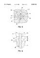
- FIG. 3is a cross section view of the fastener taken along line 3--3 of FIG. 2;
- FIG. 4is an enlarged, fragmentary, side view of the fastener of FIG. 2;
- FIG. 5is an enlarged, fragmentary, cross section view of the fastener and new log taken along line 5--5 of FIG. 1;
- FIG. 6is an enlarged cross section view of Area 6 of FIG. 1.
- Log fastener 10is especially adapted for fastening together a new, unsecured log 12' to an adjacent, secured log 12 or logs in constructing a log home.
- the logs 12, 12'which are illustrated in FIG. 1, are preformed and may assume a wide variety of shapes and configurations.
- the logs 12, 12'typically have substantial thicknesses which may commonly be on the order of 6, 8, 10 inches or even greater thicknesses.
- the logs 12, 12'are formed in an efficient, mass produced process which provides a generally uniform shape so as to produce generally uniformly spaced upper and lower planar surfaces 14, 16.
- the logs 12, 12'also typically have various tongues 18, grooves 20, slots 22 and notches (not illustrated) which are used in the construction process.
- the fastener 10may also have application in fastening together beams, landscape ties, rails, etc. which have a substantial thickness.
- fastener 10includes an integral hex head 24, flange 26, and shank 28.
- the shank 28is comprised of a shaft segment 30 having a substantially uniform diameter and a transition segment 32 disposed intermediate the shaft segment 30 and the flange 26.
- the transition segment 32has a frustoconical shape where the diameter adjacent the flange 26 is greater than the diameter adjacent the shaft segment 30.
- a pair of diametrically opposed fins 34project radially outward from the transition segment 32 and a portion of the shaft segment 30.
- the fins 34are configured so that when the fins 34 engage the top surface 14 of the log 12' and the fastener 10 is torqued, the fins 34 drill a counter-bore 36.
- the head 24may thus be countersunk into the new log 12' as part of the fastener driving process.
- the counter-bore 36may be drilled as a separate operation and the fins eliminated.
- the shaft segment 30is dimensioned to axially extend a distance 40 substantially equal to the entire thickness of the log 12, 12'.
- the shank 28also includes a threaded segment 38 which typically axially extends a distance 42 on the order of two (2) inches.
- the threaded segment 38terminates in a point 44 of a type known in the art for self-drilling a bore 46 into the logs 12, 12' (FIG. 5).
- a pair of diametrically opposed wings 48project outwardly from the shaft segment 30 of the shank 28.
- the outer diameter 50 of the wings 48is substantially equal to the thread diameter 52.
- the wings 48ream the bore wall 54 behind the thread segment 38, thereby enlarging the diameter of the bore 46, as the fastener 10 is driven into the new log 12', as shown in FIG. 5.
- the gap 56 between the surfaces 58 of the shaft segment 30 and the bore wall 54minimizes engagement between the shaft segment 30 and the bore wall 54, reducing the friction between the new log 12' and the fastener 10 and allowing the fastener 10 to be installed with less torque.
- the clearance 56also facilitates relative movement between the fastener 10 and the new log 12' due to log shrinkage or settling.
- each of the wings 48has a base 60 and an extension portion 62 extending from the base 60 to a cutting edge 64.
- the extreme axial ends of the cutting edge 64may be beveled.
- the base 60has a trapezoidal cross-section, such that the bottom 66 of the base 60 has a width 68 which is wider than the width 70 of the top 72 of the base 60, to provide better mechanical support to the extension portion 62.
- the radially inner, bottom 66 of the base 60is set below the surface 58 of the shaft segment 30 and the height of the base is selected such that the radially outer, top 72 of the base 60 does not extend beyond the surface 58 of the shaft segment 30, ensuring that there is no contact between the base 60 and the material of the new log 12'.
- the length 74 (FIG. 2) and width 70 of the extension portion 62are selected to provide a cross-sectional area which is great enough to provide the mechanical strength required to remove material from the bore wall 54 while minimizing the contact between the wings 48 and the log material to reduce friction therebetween.
- the length 74 of the extension portionis substantially equal to the distance 75 between adjacent threads to optimize the reaming characteristics of the cutting edge 64 while minimizing the surface area.
- the wings 48are positioned at an axial distance 76 from the threaded segment 38.
- the length 74 of the extension portion 62 and the length of the distance 76are selected such that the lead end 77 of the extension portion 62 penetrates the upper surface 14 of the secured log 12 and enlarges the drilled bore 46 of the secured log 12 immediately adjacent the upper surface 14 of the secured log 12 (FIG. 6). This ensures that the full length of the drilled bore 46 in the new log 12' is enlarged by the wings 48, minimizing the friction between the new log 12' and the shaft segment 30 of the fastener 10.
- the minimum value of the length 79 of the penetrationis selected such that the force generated by lateral relative movement between the logs 12, 12' will result in a bending force rather than in a shear force.
- the maximum value of the length 79 of the penetrationis selected such that the thread connection between the threaded segment 38 of the shank 28 and the secured log 12 will not be compromised.
- the shank 28is preferably coated with a lubricous coating (partially illustrated).
- the coatingaids in the installation by further lessening the friction during the installation process.
- the lubricous coatingwill allow the logs 12, 12' to settle by providing a limited degree of lubricated movement along the fastener shank 28.
- the lubricous coatingis a XylanTM coating which contains TeflonTM and is applied via a fluorocarbon.
- the logs 12, 12'are fastened together by applying a torque to the fasteners 10 without initially pre-drilling either a through bore or a counter-bore into the new log 12'.
- a fastener holder attachmentis used in conjunction with an automatic screw gun (neither illustrated) to support the fastener 10 and ensure that a sufficient downward force is exerted on the fastener 10 for threading the fastener 10 through the new log 12' and into the secured log 12.
- the fastener 10self-drills and self-taps into the logs 12, 12', and as it does so, forms a bore 46 which is dimensioned to receive the shaft segment 30.
- the pair of wings 48enter the bore 46 and function to enlarge the diameter of the bore 46 to reduce contact between the shaft segment 30 and the bore wall 54 and thereby reduce friction therebetween.
- the pair of fins 34function to form a counter-bore 36 for sinking the head 24 below the top surface 14 of the new log 12'.
- the shaft segment 30 and the threaded segment 38are dimensioned so that the fastener 10 only threadably engages the secured (bottom) log 12 when the fastener 10 is fully driven.
- the lubricous coatingfacilitates the installation process.
- the total length of the transition segment 32 and the shaft segment 30is approximately 8 inches and the length of the threaded segment 38 is approximately 2 inches.
- the diameter of the flange 26is approximately 0.445 inches.
- the diameter of the intermediate shaft segment 30is approximately 0.189 inches.
- the root diameter 78 of the threaded segment 38is 0.172 inches and the thread diameter 52 is 0.260 inches.
- the diameter 50 of the pair of wings 48is 0.260 inches.
- the length 74 of each wing 48is 0.128 inches and the distance 76 from the mid-point of each wing 48 to the threaded segment 38 may be 0.125 to 0.250 inches and preferably is 0.200 inches.
- the width 70 of the top 72 of the base 60 and the extension portion 62 of each wing 48is 0.020 inches, the width 68 of the bottom 66 of the base 60 is 0.070 inches, and the angle 80 formed by the sides of the base 60 is 80-90°.
- the height 82 of the wing 48is 0.068 inches, the height 84 of the extension portion 62 is 0.037 inches, and the radius 86 formed between the leading edge of the extension portion 62 and the surface 58 of the shaft segment 30 is 0.074 inches (FIG. 2).
- Table 1provides test results comparing the performance of a standard (std.) ten (10) inch threaded fastener with a first ten (10) inch wing fastener (wing) in accordance with the invention having no lubricous coating and with a second ten (10) inch wing fastener (wing) in accordance with the invention having a coating of XylanTM.
- the test logswere composed of pressure treated wood (PT), southern yellow pine (SthYwPine), or oak (OAK).
- the data provided in the tableincludes the start and finish times, the max torque required to install each fastener, the % change in the max torque from the subject fasteners to the conventional fastener, the total force (represented by the total area) required to install each fastener, and the % change in the total force from the subject fasteners to the conventional fastener.
- the test results provided in Table 1show that the maximum torque and total force required to install a fastener 10 in accordance with the present invention is less than that required to install a comparable length conventional fastener in pressure treated wood and southern yellow pine, two of the most common building materials.
- the maximum torque and total force required to install the fastener 10 in pressure treated woodwas reduced by at least thirty percent (30%) and twenty-one percent (21%), respectively.
- the maximum torque and total force required to install the fastener 10 in southern yellow pinewas reduced by at least ten percent (10%) and eighteen percent (18%), respectively.
- the test resultsalso indicate that although the maximum torque required to install fastener 10 in oak is less than that required to install a conventional fastener, the total force is approximately the same.
Landscapes
- Engineering & Computer Science (AREA)
- General Engineering & Computer Science (AREA)
- Mechanical Engineering (AREA)
- Physics & Mathematics (AREA)
- Geometry (AREA)
- Life Sciences & Earth Sciences (AREA)
- Chemical & Material Sciences (AREA)
- Dispersion Chemistry (AREA)
- Wood Science & Technology (AREA)
- Joining Of Building Structures In Genera (AREA)
Abstract
Description
TABLE 1 __________________________________________________________________________SCREW Xylan TIME (sec) MAX TORQUE TOTAL AREA TYPE CLEAR COAT WOOD start finish lb-in % CHANGE lb-in-sec % CHANGE __________________________________________________________________________std. Y PT 1.0 9.0 50.8 -- 290 -- wing Y 9.1 35.9 30 225 22 wing N 9.0 34.2 33 227 21 std. Y SthYwPine 1.0 9.1 58.6 -- 343 -- wing Y SthYwPine 1.0 9.0 42.6 27 259 24 wing N SthYwPine 1.1 9.0 45.5 22 280 18 std. Y SthYwPine 1.0 9.0 64.4 -- 372 -- wing Y SthYwPine 1.1 9.0 57.6 10 296 20 wing N SthYwPine 1.0 9.0 50.6 21.0 295 20 std. Y SthYwPine 1.1 9.0 74.9 -- 428 -- wing Y SthYwPine 1.1 9.0 59.6 20.0 341 20 wing N SthYwPine 1.1 9.0 61.8 17.0 345 19 std. Y 9.1 102.0 -- 621 -- wing Y 9.1 82.3 19.0 586 6 wing N 9.0 86.2 15.0 632 -2 std. Y 9.1 87.1 -- 503 -- wing Y 9.1 85.9 1.0 507 -1 wing N 9.1 80.9 7.0 556 -9 __________________________________________________________________________
Claims (16)
Priority Applications (1)
| Application Number | Priority Date | Filing Date | Title |
|---|---|---|---|
| US09/138,278US6050765A (en) | 1998-08-21 | 1998-08-21 | Fastener for logs and fastening technique therefor |
Applications Claiming Priority (1)
| Application Number | Priority Date | Filing Date | Title |
|---|---|---|---|
| US09/138,278US6050765A (en) | 1998-08-21 | 1998-08-21 | Fastener for logs and fastening technique therefor |
Publications (1)
| Publication Number | Publication Date |
|---|---|
| US6050765Atrue US6050765A (en) | 2000-04-18 |
Family
ID=22481304
Family Applications (1)
| Application Number | Title | Priority Date | Filing Date |
|---|---|---|---|
| US09/138,278Expired - LifetimeUS6050765A (en) | 1998-08-21 | 1998-08-21 | Fastener for logs and fastening technique therefor |
Country Status (1)
| Country | Link |
|---|---|
| US (1) | US6050765A (en) |
Cited By (40)
| Publication number | Priority date | Publication date | Assignee | Title |
|---|---|---|---|---|
| US6361259B1 (en)* | 1996-04-17 | 2002-03-26 | Sfs Industrie Holding Ag | Screw for torque-limited fastening |
| US6385929B1 (en)* | 1999-10-29 | 2002-05-14 | Richard J. Englehart | Log and screw pin building system |
| EP1253334A1 (en)* | 2001-04-25 | 2002-10-30 | Aoyama Seisakusho Co., Ltd. | Threaded fastener and method of clamping using the same |
| US6666638B2 (en)* | 2001-02-15 | 2003-12-23 | Phillips Screw Company | Deck screw having multiple threaded sections |
| US20040134142A1 (en)* | 2003-01-14 | 2004-07-15 | Stutts H. Craig | Log home construction system |
| US20040163358A1 (en)* | 2003-02-26 | 2004-08-26 | Gregory Clarke | System for constructing log structures |
| US20040197139A1 (en)* | 2001-08-06 | 2004-10-07 | Mcgovern Hubert T. | Deck screws suitable for use with composite lumber |
| US20040228705A1 (en)* | 2003-05-16 | 2004-11-18 | Abbott-Interfast Corporation. | Fasteners for composite material |
| US6851233B2 (en)* | 2001-09-15 | 2005-02-08 | Richard Morgenstern | Cast log structure |
| US20050235779A1 (en)* | 2002-07-15 | 2005-10-27 | Haytayan Harry M | Method and apparatus for fastening together structural components |
| US20060201581A1 (en)* | 2005-03-10 | 2006-09-14 | Richard Belinda | Timber fastener and method of manufacturing and employing the same |
| US20070059122A1 (en)* | 2005-09-09 | 2007-03-15 | Kwantex Research Inc. | Screw for composite board |
| US20070128001A1 (en)* | 2005-12-07 | 2007-06-07 | Guo-Cai Su | Screw with two types of threads |
| US20070130852A1 (en)* | 2003-12-19 | 2007-06-14 | Sfs Intec Holding Ag | Wood wall construction made of wooden beams |
| US20070147973A1 (en)* | 2005-12-22 | 2007-06-28 | Cyril Laan | Dual threaded screw for composite materials |
| US20070271761A1 (en)* | 2002-07-15 | 2007-11-29 | Haytayan Harry M | Apparatus and method for fastening together structural components |
| US20070292235A1 (en)* | 2006-06-15 | 2007-12-20 | Katsumi Shinjo | Self-Drilling Reaming Screw for Hard Materials |
| US20080263984A1 (en)* | 2007-04-27 | 2008-10-30 | Gillis Timothy F | Plug finishing system and tool therefor |
| US20080273939A1 (en)* | 2004-12-03 | 2008-11-06 | Simpson Strong-Tie Company, Inc. | Variably Threaded Screw |
| US20090151278A1 (en)* | 2007-12-18 | 2009-06-18 | Cornerstone Specialty Wood Products, Llc | Flooring system and method for installing involving a corrugated member and a panel flooring member |
| US7604445B1 (en)* | 1999-04-07 | 2009-10-20 | A-Z Ausrustung Und Zubehor Gmbh & Co. Kg | Countersunk head screw |
| US7677854B2 (en)* | 2006-01-12 | 2010-03-16 | Spax International Gmbh & Co. Kg | Self-boring and self-tapping screw |
| US20100071313A1 (en)* | 2007-01-16 | 2010-03-25 | Pierre-Louis Zuber | Method of assembling strips of wood |
| US20110146171A1 (en)* | 2008-04-28 | 2011-06-23 | Torkel Flatland | Thermally insulating building construction element assembly, and timber or lumber member for same |
| US20110164944A1 (en)* | 2009-05-22 | 2011-07-07 | Hughes Barry J | Low energy screws for wood and similar materials |
| US20110229285A1 (en)* | 2008-09-30 | 2011-09-22 | Flueckiger Werner | Fastening device |
| US9322422B2 (en) | 2012-07-23 | 2016-04-26 | Simpson Strong-Tie Company, Inc. | Fastener with drill pilot and reversed threaded regions |
| US9482258B2 (en) | 2012-05-10 | 2016-11-01 | Simpson Strong-Tie Company, Inc. | Fastener with multiple threaded regions |
| US9523383B2 (en) | 2013-03-26 | 2016-12-20 | Simpson Strong-Tie Company, Inc. | Variable thread fastener |
| US20170037893A9 (en)* | 2013-03-15 | 2017-02-09 | Kevin G. Walters | Fastener for Installation Tool for Roof Truss Framing and Construction System |
| US9651079B2 (en) | 2013-03-21 | 2017-05-16 | Simpson Strong-Tie Company, Inc. | Fastener with prolate cross-section |
| US20180202479A1 (en)* | 2017-01-16 | 2018-07-19 | Altenloh, Brinck & Co. U.S. Inc. | Threaded Fastener |
| US20190136898A1 (en)* | 2017-11-08 | 2019-05-09 | Chun Yu Works & Co., Ltd. | Self-tapping screw with drilling wing |
| US20200137897A1 (en)* | 2017-03-21 | 2020-04-30 | Phoenix Contact Gmbh & Co. Kg | Electronics housing and method for housing electronic components |
| US11181138B2 (en) | 2013-03-26 | 2021-11-23 | Simpson Strong-Tie Company, Inc. | Variable thread knurl fastener |
| US20220235809A1 (en)* | 2019-07-03 | 2022-07-28 | Hilti Aktiengesellschaft | Dry-construction screw |
| US11433511B2 (en) | 2013-03-15 | 2022-09-06 | Omg, Inc. | Dual positionable fastener installation tool adaptor |
| US11624392B2 (en) | 2019-12-27 | 2023-04-11 | Wei-Chih Chen | Wing-shaped thrust screw assembly |
| US20230160413A1 (en)* | 2021-11-23 | 2023-05-25 | Omg, Inc. | Threaded Fastener With Scalloped Minor Diameter |
| US11975424B2 (en) | 2013-03-15 | 2024-05-07 | Omg, Inc. | Multiple entry angle adaptor with locator for fastener installation tool |
Citations (5)
| Publication number | Priority date | Publication date | Assignee | Title |
|---|---|---|---|---|
| US3358548A (en)* | 1966-04-14 | 1967-12-19 | Illinois Tool Works | Drill screw |
| US3869219A (en)* | 1972-10-30 | 1975-03-04 | Robert Neil Wilson | Drill screw |
| US4881861A (en)* | 1987-09-08 | 1989-11-21 | Itw Limited | Fastening assembly |
| US5400845A (en)* | 1992-12-21 | 1995-03-28 | Olympic Manufacturing Group, Inc. | Technique for fastening logs and fastener therefor |
| US5516248A (en)* | 1994-09-07 | 1996-05-14 | Abbott-Interfast Corporation | Low torque wood screw |
- 1998
- 1998-08-21USUS09/138,278patent/US6050765A/ennot_activeExpired - Lifetime
Patent Citations (5)
| Publication number | Priority date | Publication date | Assignee | Title |
|---|---|---|---|---|
| US3358548A (en)* | 1966-04-14 | 1967-12-19 | Illinois Tool Works | Drill screw |
| US3869219A (en)* | 1972-10-30 | 1975-03-04 | Robert Neil Wilson | Drill screw |
| US4881861A (en)* | 1987-09-08 | 1989-11-21 | Itw Limited | Fastening assembly |
| US5400845A (en)* | 1992-12-21 | 1995-03-28 | Olympic Manufacturing Group, Inc. | Technique for fastening logs and fastener therefor |
| US5516248A (en)* | 1994-09-07 | 1996-05-14 | Abbott-Interfast Corporation | Low torque wood screw |
Cited By (74)
| Publication number | Priority date | Publication date | Assignee | Title |
|---|---|---|---|---|
| US6361259B1 (en)* | 1996-04-17 | 2002-03-26 | Sfs Industrie Holding Ag | Screw for torque-limited fastening |
| US7604445B1 (en)* | 1999-04-07 | 2009-10-20 | A-Z Ausrustung Und Zubehor Gmbh & Co. Kg | Countersunk head screw |
| US6385929B1 (en)* | 1999-10-29 | 2002-05-14 | Richard J. Englehart | Log and screw pin building system |
| US20040151559A1 (en)* | 2001-02-15 | 2004-08-05 | Arnold Craven | Screw |
| US6941635B2 (en) | 2001-02-15 | 2005-09-13 | Phillips Screw Company | Screw for remnant-producing alternative lumber material |
| US6666638B2 (en)* | 2001-02-15 | 2003-12-23 | Phillips Screw Company | Deck screw having multiple threaded sections |
| US7695228B2 (en) | 2001-02-15 | 2010-04-13 | Phillips Fastener, Llc | Screw |
| US20050265806A1 (en)* | 2001-02-15 | 2005-12-01 | Arnold Craven | Screw |
| US20100196122A1 (en)* | 2001-02-15 | 2010-08-05 | Arnold Craven | Screw |
| EP1253334A1 (en)* | 2001-04-25 | 2002-10-30 | Aoyama Seisakusho Co., Ltd. | Threaded fastener and method of clamping using the same |
| US20040197139A1 (en)* | 2001-08-06 | 2004-10-07 | Mcgovern Hubert T. | Deck screws suitable for use with composite lumber |
| US20070147974A1 (en)* | 2001-08-06 | 2007-06-28 | Mcgovern Hubert T | Deck screw and installation method for composite lumber |
| US7189045B2 (en) | 2001-08-06 | 2007-03-13 | Omg, Inc. | Deck screws suitable for use with composite lumber |
| US7367768B2 (en) | 2001-08-06 | 2008-05-06 | Omg, Inc. | Deck screw and installation method for composite lumber |
| US6851233B2 (en)* | 2001-09-15 | 2005-02-08 | Richard Morgenstern | Cast log structure |
| US20050235779A1 (en)* | 2002-07-15 | 2005-10-27 | Haytayan Harry M | Method and apparatus for fastening together structural components |
| US8074348B2 (en) | 2002-07-15 | 2011-12-13 | Haytayan Harry M | Apparatus and method for fastening together structural components |
| US7377019B2 (en)* | 2002-07-15 | 2008-05-27 | Haytayan Harry M | Method and apparatus for fastening together structural components |
| US20070271761A1 (en)* | 2002-07-15 | 2007-11-29 | Haytayan Harry M | Apparatus and method for fastening together structural components |
| US6904728B2 (en)* | 2003-01-14 | 2005-06-14 | Heritage Log Homes, Inc. | Log home construction system |
| US20040134142A1 (en)* | 2003-01-14 | 2004-07-15 | Stutts H. Craig | Log home construction system |
| US7594370B2 (en) | 2003-02-26 | 2009-09-29 | Pointblank Design Inc. | Butt joint for logs in log structures |
| US7313890B2 (en) | 2003-02-26 | 2008-01-01 | Pointblank Design Inc. | Wall opening support system |
| US7594367B2 (en) | 2003-02-26 | 2009-09-29 | Pointblank Design Inc. | Connection structure for a log wall |
| US7117647B2 (en) | 2003-02-26 | 2006-10-10 | Pointblank Design Inc. | System for constructing log structures |
| US20040163358A1 (en)* | 2003-02-26 | 2004-08-26 | Gregory Clarke | System for constructing log structures |
| US20070094961A1 (en)* | 2003-02-26 | 2007-05-03 | Pointblank Design Inc. | Butt Joint For Logs In Log Structures |
| US20060288656A1 (en)* | 2003-02-26 | 2006-12-28 | Pointblank Design Inc. | Exterior casing structure for an opening in a log wall |
| US20060288655A1 (en)* | 2003-02-26 | 2006-12-28 | Pointblank Design Inc. | Connection structure for a log wall |
| US20040228705A1 (en)* | 2003-05-16 | 2004-11-18 | Abbott-Interfast Corporation. | Fasteners for composite material |
| US8430618B2 (en) | 2003-05-16 | 2013-04-30 | Abbott-Interfast Corporation | Fasteners for composite material |
| US20070130852A1 (en)* | 2003-12-19 | 2007-06-14 | Sfs Intec Holding Ag | Wood wall construction made of wooden beams |
| US20080273939A1 (en)* | 2004-12-03 | 2008-11-06 | Simpson Strong-Tie Company, Inc. | Variably Threaded Screw |
| US20060201581A1 (en)* | 2005-03-10 | 2006-09-14 | Richard Belinda | Timber fastener and method of manufacturing and employing the same |
| US20070059122A1 (en)* | 2005-09-09 | 2007-03-15 | Kwantex Research Inc. | Screw for composite board |
| US8894339B2 (en) | 2005-12-02 | 2014-11-25 | Simpson Strong-Tie Company, Inc. | Variably threaded screw |
| US20070128001A1 (en)* | 2005-12-07 | 2007-06-07 | Guo-Cai Su | Screw with two types of threads |
| US20070147973A1 (en)* | 2005-12-22 | 2007-06-28 | Cyril Laan | Dual threaded screw for composite materials |
| US7255523B2 (en) | 2005-12-22 | 2007-08-14 | Prime Source Building Products, Inc. | Dual threaded screw for composite materials |
| US7677854B2 (en)* | 2006-01-12 | 2010-03-16 | Spax International Gmbh & Co. Kg | Self-boring and self-tapping screw |
| US20070292235A1 (en)* | 2006-06-15 | 2007-12-20 | Katsumi Shinjo | Self-Drilling Reaming Screw for Hard Materials |
| US20100071313A1 (en)* | 2007-01-16 | 2010-03-25 | Pierre-Louis Zuber | Method of assembling strips of wood |
| US8202032B2 (en) | 2007-04-27 | 2012-06-19 | Handy & Harman | Plug finishing system and tool therefor |
| US20080263984A1 (en)* | 2007-04-27 | 2008-10-30 | Gillis Timothy F | Plug finishing system and tool therefor |
| US8104248B2 (en)* | 2007-04-27 | 2012-01-31 | Handy & Harman | Plug finishing system and tool therefor |
| US20090151278A1 (en)* | 2007-12-18 | 2009-06-18 | Cornerstone Specialty Wood Products, Llc | Flooring system and method for installing involving a corrugated member and a panel flooring member |
| US20110146171A1 (en)* | 2008-04-28 | 2011-06-23 | Torkel Flatland | Thermally insulating building construction element assembly, and timber or lumber member for same |
| US20110229285A1 (en)* | 2008-09-30 | 2011-09-22 | Flueckiger Werner | Fastening device |
| US9334888B2 (en)* | 2008-09-30 | 2016-05-10 | Werner Flückiger | Fastening device |
| US20110164944A1 (en)* | 2009-05-22 | 2011-07-07 | Hughes Barry J | Low energy screws for wood and similar materials |
| US9297402B2 (en)* | 2009-05-22 | 2016-03-29 | Phillips Screw Company | Low energy screws for wood and similar materials |
| US10954990B2 (en) | 2009-05-22 | 2021-03-23 | Phillips Screw Company | Low energy screws for wood and similar materials |
| US10371193B2 (en) | 2009-05-22 | 2019-08-06 | Phillips Screw Company | Low energy screws for wood and similar materials |
| US9903406B2 (en) | 2009-05-22 | 2018-02-27 | Phillips Screw Company | Low energy screws for wood and similar materials |
| US9482258B2 (en) | 2012-05-10 | 2016-11-01 | Simpson Strong-Tie Company, Inc. | Fastener with multiple threaded regions |
| US10480559B2 (en) | 2012-05-10 | 2019-11-19 | Simpson Strong-Tie Company, Inc. | Fastener with head cutting structure |
| US9322422B2 (en) | 2012-07-23 | 2016-04-26 | Simpson Strong-Tie Company, Inc. | Fastener with drill pilot and reversed threaded regions |
| US20170037893A9 (en)* | 2013-03-15 | 2017-02-09 | Kevin G. Walters | Fastener for Installation Tool for Roof Truss Framing and Construction System |
| US10859109B2 (en) | 2013-03-15 | 2020-12-08 | Omg, Inc. | Fastener for installation tool for roof truss framing and construction system |
| US11975424B2 (en) | 2013-03-15 | 2024-05-07 | Omg, Inc. | Multiple entry angle adaptor with locator for fastener installation tool |
| US10018215B2 (en)* | 2013-03-15 | 2018-07-10 | Handy & Harman | Fastener for installation tool for roof truss framing and construction system |
| US11433511B2 (en) | 2013-03-15 | 2022-09-06 | Omg, Inc. | Dual positionable fastener installation tool adaptor |
| US11268561B2 (en) | 2013-03-15 | 2022-03-08 | Omg, Inc. | Installation tool and fastener for roof truss framing and construction system |
| US9651079B2 (en) | 2013-03-21 | 2017-05-16 | Simpson Strong-Tie Company, Inc. | Fastener with prolate cross-section |
| US11181138B2 (en) | 2013-03-26 | 2021-11-23 | Simpson Strong-Tie Company, Inc. | Variable thread knurl fastener |
| US9523383B2 (en) | 2013-03-26 | 2016-12-20 | Simpson Strong-Tie Company, Inc. | Variable thread fastener |
| US20180202479A1 (en)* | 2017-01-16 | 2018-07-19 | Altenloh, Brinck & Co. U.S. Inc. | Threaded Fastener |
| US10823220B2 (en)* | 2017-01-16 | 2020-11-03 | Altenloh, Brinck & Co. U.S. Inc. | Threaded fastener |
| US11304314B2 (en)* | 2017-03-21 | 2022-04-12 | Phoenix Contact Gmbh & Co. Kg | Electronics housing and method for housing electronic components |
| US20200137897A1 (en)* | 2017-03-21 | 2020-04-30 | Phoenix Contact Gmbh & Co. Kg | Electronics housing and method for housing electronic components |
| US20190136898A1 (en)* | 2017-11-08 | 2019-05-09 | Chun Yu Works & Co., Ltd. | Self-tapping screw with drilling wing |
| US20220235809A1 (en)* | 2019-07-03 | 2022-07-28 | Hilti Aktiengesellschaft | Dry-construction screw |
| US11624392B2 (en) | 2019-12-27 | 2023-04-11 | Wei-Chih Chen | Wing-shaped thrust screw assembly |
| US20230160413A1 (en)* | 2021-11-23 | 2023-05-25 | Omg, Inc. | Threaded Fastener With Scalloped Minor Diameter |
Similar Documents
| Publication | Publication Date | Title |
|---|---|---|
| US6050765A (en) | Fastener for logs and fastening technique therefor | |
| US4601625A (en) | Self drilling threaded insert for drywall | |
| US6666638B2 (en) | Deck screw having multiple threaded sections | |
| US7255523B2 (en) | Dual threaded screw for composite materials | |
| US5400845A (en) | Technique for fastening logs and fastener therefor | |
| US5516248A (en) | Low torque wood screw | |
| US8408856B2 (en) | Self-drilling fastener | |
| US20070204552A1 (en) | Plastic composite deck screw | |
| EP1748198A2 (en) | Hollow self-drilling fastener | |
| AU677568B2 (en) | Improved fixing | |
| US5865584A (en) | Plywood fastener for affixing plywood to light gauge sheet metal | |
| US11598362B2 (en) | Screw fasteners for use in building construction | |
| EP1485627B1 (en) | Fixing device and method for fixing to a substrate | |
| US9016995B1 (en) | Self-countersinking fastener | |
| AU2021290294B2 (en) | A multipurpose screw | |
| AU2010200536A1 (en) | Self-drilling screw | |
| US20040096293A1 (en) | Truss screw | |
| AU2019232872B2 (en) | Screw fasteners for use in building construction | |
| AU2021221841A1 (en) | Drill tip screw | |
| JP2025030410A (en) | Self-drilling screws | |
| HK1072970B (en) | Fixing device and method for fixing to a substrate |
Legal Events
| Date | Code | Title | Description |
|---|---|---|---|
| AS | Assignment | Owner name:OLYMPIC MANUFACTURING GROUP, INC., MASSACHUSETTS Free format text:ASSIGNMENT OF ASSIGNORS INTEREST;ASSIGNORS:MCGOVERN, HUBERT T.;EMMONDS, TODD W.;REEL/FRAME:009407/0933 Effective date:19980819 | |
| STCF | Information on status: patent grant | Free format text:PATENTED CASE | |
| FPAY | Fee payment | Year of fee payment:4 | |
| AS | Assignment | Owner name:CONGRESS FINANCIAL CORPORATION, AS AGENT, NEW YORK Free format text:SECURITY INTEREST;ASSIGNOR:OLYMPIC MANUFACTURING GROUP, INC.;REEL/FRAME:015361/0274 Effective date:20040331 | |
| AS | Assignment | Owner name:ABLECO FINANCE LLC, NEW YORK Free format text:SECURITY INTEREST;ASSIGNOR:OLYMPIC MANUFACTURING GROUP, INC.;REEL/FRAME:015246/0001 Effective date:20040330 | |
| AS | Assignment | Owner name:CANPARTNERS INVESTMENTS IV, LLC, AS COLLATERAL AGE Free format text:ASSIGNMENT OF SECURITY INTEREST;ASSIGNOR:ABLECO FINANCE LLC;REEL/FRAME:015334/0172 Effective date:20041029 | |
| AS | Assignment | Owner name:OMG, INC., MASSACHUSETTS Free format text:CHANGE OF NAME;ASSIGNOR:OLYMPIC MANUFACTURING GROUP, INC.;REEL/FRAME:016800/0571 Effective date:20041209 | |
| FPAY | Fee payment | Year of fee payment:8 | |
| AS | Assignment | Owner name:STEEL PARTNERS II LIQUIDATING SERIES TRUST - SERIE Free format text:SECURITY AGREEMENT;ASSIGNOR:STEEL PARTNERS II, L.P.;REEL/FRAME:023741/0717 Effective date:20090715 | |
| AS | Assignment | Owner name:ABLECO, L.L.C., AS AGENT, NEW YORK Free format text:PATENT COLLATERAL ASSIGNMENT AND SECURITY AGREEMENT;ASSIGNOR:OMG, INC. (F/K/A OLYMPIC MANUFACTURING GROUP, INC.);REEL/FRAME:025150/0295 Effective date:20101015 Owner name:ABLECO, L.L.C., AS AGENT, NEW YORK Free format text:PATENT COLLATERAL ASSIGNMENT AND SECURITY AGREEMENT;ASSIGNOR:OMG, INC. (F/K/A OLYMPIC MANUFACTURING GROUP, INC.);REEL/FRAME:025150/0481 Effective date:20101015 | |
| FPAY | Fee payment | Year of fee payment:12 | |
| AS | Assignment | Owner name:OMG, INC., MASSACHUSETTS Free format text:RELEASE OF PATENT COLLATERAL ASSIGNMENTS;ASSIGNOR:ABELCO, L.L.C.;REEL/FRAME:029299/0620 Effective date:20121108 | |
| AS | Assignment | Owner name:OMG, INC. (F/K/A OLYMPIC MANUFACTURING GROUP, INC. Free format text:RELEASE OF SECURITY INTEREST IN PATENTS;ASSIGNOR:WELLS FARGO BANK, NATIONAL ASSOCIATION;REEL/FRAME:029302/0414 Effective date:20121108 | |
| AS | Assignment | Owner name:PNC BANK, NATIONAL ASSOCIATION, AS COLLATERAL AGEN Free format text:SECURITY AGREEMENT;ASSIGNORS:ARLON LLC;CONTINENTAL INDUSTRIES, INC.;HANDY & HARMAN;AND OTHERS;REEL/FRAME:029308/0304 Effective date:20121108 |