US6050092A - Stirling cycle generator control system and method for regulating displacement amplitude of moving members - Google Patents
Stirling cycle generator control system and method for regulating displacement amplitude of moving membersDownload PDFInfo
- Publication number
- US6050092A US6050092AUS09/143,026US14302698AUS6050092AUS 6050092 AUS6050092 AUS 6050092AUS 14302698 AUS14302698 AUS 14302698AUS 6050092 AUS6050092 AUS 6050092A
- Authority
- US
- United States
- Prior art keywords
- load
- output
- moving member
- circuitry
- operative
- Prior art date
- Legal status (The legal status is an assumption and is not a legal conclusion. Google has not performed a legal analysis and makes no representation as to the accuracy of the status listed.)
- Expired - Lifetime
Links
- 238000000034methodMethods0.000titleclaimsabstractdescription9
- 238000006073displacement reactionMethods0.000titleclaimsdescription21
- 230000001105regulatory effectEffects0.000titleclaimsdescription13
- 230000033001locomotionEffects0.000claimsabstractdescription25
- 230000002596correlated effectEffects0.000claimsabstractdescription6
- 230000001276controlling effectEffects0.000claimsdescription4
- 230000000875corresponding effectEffects0.000claimsdescription3
- 238000001514detection methodMethods0.000claimsdescription2
- 238000012544monitoring processMethods0.000claimsdescription2
- 238000010586diagramMethods0.000description8
- 238000003475laminationMethods0.000description8
- 230000001052transient effectEffects0.000description5
- XEEYBQQBJWHFJM-UHFFFAOYSA-NIronChemical compound[Fe]XEEYBQQBJWHFJM-UHFFFAOYSA-N0.000description4
- 239000012530fluidSubstances0.000description4
- 230000009467reductionEffects0.000description4
- 230000004044responseEffects0.000description4
- 230000008859changeEffects0.000description3
- 230000003071parasitic effectEffects0.000description3
- 230000000712assemblyEffects0.000description2
- 238000000429assemblyMethods0.000description2
- 238000006243chemical reactionMethods0.000description2
- 238000010276constructionMethods0.000description2
- 230000005669field effectEffects0.000description2
- 239000000446fuelSubstances0.000description2
- 239000007789gasSubstances0.000description2
- 229910052742ironInorganic materials0.000description2
- 230000001172regenerating effectEffects0.000description2
- 230000005355Hall effectEffects0.000description1
- UFHFLCQGNIYNRP-UHFFFAOYSA-NHydrogenChemical compound[H][H]UFHFLCQGNIYNRP-UHFFFAOYSA-N0.000description1
- 230000002159abnormal effectEffects0.000description1
- 238000013459approachMethods0.000description1
- 230000033228biological regulationEffects0.000description1
- 239000003990capacitorSubstances0.000description1
- 238000004891communicationMethods0.000description1
- 238000013016dampingMethods0.000description1
- 230000007423decreaseEffects0.000description1
- 238000013461designMethods0.000description1
- 230000003292diminished effectEffects0.000description1
- 230000000694effectsEffects0.000description1
- 238000010304firingMethods0.000description1
- 230000004907fluxEffects0.000description1
- 230000006870functionEffects0.000description1
- 231100001261hazardousToxicity0.000description1
- 238000010438heat treatmentMethods0.000description1
- 239000001307heliumSubstances0.000description1
- 229910052734heliumInorganic materials0.000description1
- SWQJXJOGLNCZEY-UHFFFAOYSA-Nhelium atomChemical compound[He]SWQJXJOGLNCZEY-UHFFFAOYSA-N0.000description1
- 239000001257hydrogenSubstances0.000description1
- 229910052739hydrogenInorganic materials0.000description1
- 238000004519manufacturing processMethods0.000description1
- 238000012986modificationMethods0.000description1
- 230000004048modificationEffects0.000description1
- 230000003287optical effectEffects0.000description1
- 238000010248power generationMethods0.000description1
- 230000008569processEffects0.000description1
- 238000004804windingMethods0.000description1
Images


Classifications
- F—MECHANICAL ENGINEERING; LIGHTING; HEATING; WEAPONS; BLASTING
- F02—COMBUSTION ENGINES; HOT-GAS OR COMBUSTION-PRODUCT ENGINE PLANTS
- F02G—HOT GAS OR COMBUSTION-PRODUCT POSITIVE-DISPLACEMENT ENGINE PLANTS; USE OF WASTE HEAT OF COMBUSTION ENGINES; NOT OTHERWISE PROVIDED FOR
- F02G1/00—Hot gas positive-displacement engine plants
- F02G1/04—Hot gas positive-displacement engine plants of closed-cycle type
- F02G1/043—Hot gas positive-displacement engine plants of closed-cycle type the engine being operated by expansion and contraction of a mass of working gas which is heated and cooled in one of a plurality of constantly communicating expansible chambers, e.g. Stirling cycle type engines
- F02G1/0435—Hot gas positive-displacement engine plants of closed-cycle type the engine being operated by expansion and contraction of a mass of working gas which is heated and cooled in one of a plurality of constantly communicating expansible chambers, e.g. Stirling cycle type engines the engine being of the free piston type
- F—MECHANICAL ENGINEERING; LIGHTING; HEATING; WEAPONS; BLASTING
- F02—COMBUSTION ENGINES; HOT-GAS OR COMBUSTION-PRODUCT ENGINE PLANTS
- F02G—HOT GAS OR COMBUSTION-PRODUCT POSITIVE-DISPLACEMENT ENGINE PLANTS; USE OF WASTE HEAT OF COMBUSTION ENGINES; NOT OTHERWISE PROVIDED FOR
- F02G2275/00—Controls
- F02G2275/20—Controls for preventing piston over stroke
Definitions
- This inventionrelates to power conversion machinery, such as a Stirling cycle engine and alternator, and more particularly to a control system and method for controlling displacement amplitude of moving members such as pistons within a Stirling cycle generator.
- Free-piston Stirling machineshave had control systems for ensuring useful power is generated by the machine while concurrently preventing overstroke of moving members that could lead to damage.
- One such control systemuses valves or ports that detune the machine to change spring forces and/or generate damping.
- Such control systemsare provided within the machine and can disrupt or unbalance the Stirling thermodynamic cycle which leads to inefficiencies.
- Such control systemsare implemented internally.
- valves or ports on pistons or moving memberstend to leak over time, tend to plug up from debris, and can fail over time.
- gas springsgenerally have high hysterisis loses. Additionally, valves do not generally perform well when subjected to abnormal or sudden load changes (i.e. transient loading conditions).
- moving members within a free-piston Stirling cycle generatorare controlled such that displacement amplitude remains within a threshold value. More particularly, such displacement amplitude is controlled within an acceptable range. Accordingly, a control system is used to regulate the maximum displacement amplitude achieved by a power piston within a Stirling cycle generator in order to prevent overstroke (a maximum threshold value), as well as to prevent engine stalling (a minimum threshold value).
- a Stirling cycle machine control systemincludes an energy converter having a moving member.
- a detectoris operatively associated with the moving member. The detector is configured to detect stroke of the moving member.
- a converter circuitis coupled with an output of the energy converter and is operative to convert output from AC to DC.
- a regulatoris coupled with the converter circuit and a useful load, and is operative to regulate DC voltage.
- a controllably variable load memberis coupled to the converter circuit and is operative to adjust load to the energy converter. Adjustment of the load to the energy converter regulates power output of the energy converter which in turn controls movement of the moving member.
- Control circuitryis signal coupled with the detector and the load member. The control circuitry is configured to receive a feedback signal correlated with the detected stroke of the moving member. The control circuitry is operative to dynamically adjust load on the energy converter to limit stroke of the moving member below a threshold level.
- a free-piston Stirling cycle generator control systemincludes a generator having a linear alternator and a power piston.
- the generatoris operative to receive energy from a source and generate an AC output.
- An output voltage detectoris operatively associated with the power piston. The output voltage detector is configured to detect a threshold voltage value corresponding to maximum acceptable stroke of the power piston.
- a converteris coupled with an output of the linear alternator. The converter is operative to convert the AC output to a DC output.
- a regulatoris coupled with the converter and a useful load. The regulator is operative to regulate DC voltage.
- a load memberis coupled to the converter, and is operative to adjust load on the linear alternator such that power output is regulated from the linear alternator.
- Control circuitryis coupled with the detector and the load member.
- the control circuitryis configured to receive a feedback signal indicative of stroke of the moving member.
- the control circuitryis operative to adjust load on the linear alternator so as to limit stroke of the moving member within a threshold value.
- This inventionalso includes a method for controlling a power piston within a free-piston Stirling cycle generator, comprising driving the generator by an external energy source so as to impart movement of a power piston of a linear alternator to generate AC output; converting the AC output to a DC output; detecting movement of the power piston by monitoring the DC output; and applying a load to the linear alternator so as to adjust load on the linear alternator so as to limit movement of the power piston within a threshold value.
- Objects, features and advantages of this inventionare to provide a control system for a free-piston Stirling cycle generator that limits movement of the moving member, or piston, within a threshold value, is relatively easy to implement, and is reliable, durable and economical.
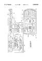
- FIG. 1is a vertical sectional view of a Stirling Cycle engine having a piston overstroke control system embodying this invention
- FIG. 2is a simplified schematic and block diagram for the moving member stroke control system of FIG. 1;
- FIG. 3is a simplified schematic circuit diagram for the rectifier and voltage regulating circuit of the moving member control system
- FIG. 4is a simplified schematic circuit diagram for the 18 Volt and reference voltage signals circuit of the moving member control system
- FIG. 5is a simplified schematic circuit diagram for the control signal circuit of the moving member control system
- FIG. 6is a simplified schematic circuit diagram for the battery charger unit of the moving member control system
- FIG. 7is a simplified schematic block and circuit diagram for a multiple engine generator system using a single common controller
- FIG. 8is a simplified schematic block and circuit diagram for a multiple engine generator system using a pair of controllers.
- FIG. 9is a simplified oscilloscope output depicting AC ripple on a full-wave rectified DC output voltage, and switching of the bank of load resistors in response to such ripple.
- FIG. 1schematically illustrates a construction for a Stirling Cycle machine in the form of a power generator 10 having a controller system of this invention.
- Generator 10is formed by assembling together a power module in the form of a linear alternator 12 and an engine module in the form of a displacer assembly 14.
- Generator 10is a thermal regenerative machine configured in operation to house a gaseous working fluid.
- Power module 12 and engine module 14are joined together with a plurality of circumferentially spaced apart threaded fasteners.
- the inside of power generator 10is filled with a charge of pressurized thermodynamic working fluid such as Helium. Alternatively, hydrogen or any or a number of suitable thermodynamically optimal working fluids can be used to fill and charge generator 10.
- a heat source 16applies heat to a heater head 18 of the engine module 14, causing power module 12 to generate a supply of electric power via a power output line 20.
- a displacer assembly 22,comprising a movable displacer piston, forms a displacer that reciprocates between a hot space 24 and a cold space 26 in response to thermodynamic heating of the hot space from heater head 18 via heat source 16.
- displacer assembly 22moves working gas between the hot and cold spaces 24 and 26.
- a linear alternatoris formed by power module 12 including a stator 27 and a mover 30.
- Stator 27comprises an array of stationary iron laminations that are secured via a plurality of fasteners within housing 38.
- the stationary laminationsform a plurality of spaced apart radially extending stationary outer stator lamination sets defining a plurality of stator poles, winding slots, and magnetic receiving slots.
- An array of annular shaped magnetsare bonded to the inner diameter of the stationary laminations for the purpose of producing magnetic flux. Each magnet is received and mounted within the plurality of magnetic receiving slots.
- mover 30comprises an array of moving iron laminations that are secured to a shaft 36.
- Shaft 36 and such laminationsmove in reciprocating motion along with power piston 28.
- Relative motion between the moving laminations of mover 30 and the stationary laminations of stator 27produces electrical power that is output through a power feed, or power output line, 20.
- power feedcomprises an AC output voltage generated by linear alternator 12.
- Shaft 36 and power piston 28are moved in axial reciprocation by pressure pulses imparted within cold space 26. Such pressure pulses are generated in response to reciprocation of displacer 22 caused by an input of heat source 16 at hot space 24. More particularly, shaft 36 and power piston 28 are carried for accurate axial reciprocation by a pair of flexure bearing assemblies 32 and 34, each formed from a plurality of flat spiral springs as known in the art and taught in the above-described Applicant's U.S. Pat. No. 5,743,091.
- control system 40is provided for controlling the amplitude of moving members within Stirling cycle generator 10 according to this invention. More particularly, control system 40 is used to regulate the maximum displacement amplitude achieved by power piston 28 and shaft 36 within housing 38 to prevent overstroke therein, to regulate the minimum displacement amplitude, and to prevent stalling.
- control system 40receives and conditions an AC output voltage 62 (see FIG. 2) via power feed 20 of linear alternator 12. More particularly, AC output voltage 62 is produced by generator 10 and rectified in order to establish a DC voltage. Furthermore, AC output voltage 62 supplies power for control system 40, and more particularly for control circuitry 42. Such DC output voltage is then compared to a reference voltage by way of control circuitry 42.
- Control circuitry 42includes a Zener diode and a voltage divider network, as discussed below with reference to FIGS. 3-8.
- Control system 40is operative to control displacement amplitude of power piston 28 within housing 38 such that overstroking does not occur.
- a threshold levelis pre-set by adjusting a Zener diode (Z 1 ) 88 (see FIG. 3) to configure control system 40, wherein contact might otherwise occur between power piston 28 and an end portion of displacer assembly 14.
- Applicant's present inventionimposes a specific voltage limit via a voltage limiter in order to limit stroke of power piston 28. More particularly, a specific DC voltage limit is imposed by using a parasitic load in the form of a controllably adjusted load member.
- Applicanthas found that attempts to manually control resistive loading for generator 10 proved difficult to achieve without encountering severe overstroking conditions for power piston 28. Applicant's invention automatically controls such process via control system 40 so as to provide instantaneous safety protection during operation thereof.
- control system 40includes control circuitry 42, a motion detector 44, and a controllable load member 46.
- Control system 40conditions AC output voltage 62 so as to deliver an output to a useful load 48.
- controllable load member 46forms the sole load placed upon linear alternator 12.
- power flow regulator 56comprises battery charging circuitry 68.
- useful load 48comprises a battery 70.
- Control circuitry 42is signal coupled with motion detector 44 and controllable load member 46, and is configured to receive a feedback signal that is correlated with the detected stroke of the moving member or power piston 28. Control circuitry 42 is operative to dynamically adjust load on generator or energy converter 10 in order to maintain stroke of power piston 28 within a desired range.
- Stirling free-piston generator 10comprises an energy converter having a moving member. More particularly, such moving member includes power piston 28 and shaft 36. It is understood that any other form of energy converter and/or generator can be used in implementing Applicant's invention. Accordingly, control system 40 comprises a Stirling cycle machine control system operative to control displacement amplitude of moving members therein.
- Motion detector 44 of control system 40is operatively associated with the moving member, such as power piston 28, and is configured to detect stroke of such moving member. More particularly, motion detector 44 comprises an output voltage detector 52 (see FIG. 2) that monitors output voltage from linear alternator 12 in order to determine displacement amplitude of power piston 28. For example, displacement amplitude of power piston 28 has been found to be linearly proportional with output voltage received from power feed 20. Accordingly, control circuitry can be adjusted to correlate output voltage with displacement amplitude. By measuring the allowable maximum stroke provided for power piston 28 within generator 10, a threshold output voltage can be determined beyond which an overstroke condition will be detected. Hence, motion detector 44 can be pre-set by adjusting control circuitry so as to detect the occurrence of such threshold voltage condition indicative of overstroke of power piston 28.
- motion detector 44can be formed from any of a number of sensors capable of detecting the positioning of moving members such as power piston 28 and shaft 36 within housing 38.
- sensorscapable of detecting the positioning of moving members such as power piston 28 and shaft 36 within housing 38.
- any of a number of sensorsincluding Hall effect sensors, optical sensors, or any other form of suitable detection device, can be utilized in detecting such overstroke condition.
- controllable load member 46is coupled with generator 10 to form a parasitic load.
- Controllable load member 46is operative to adjust load to generator 10 so as to regulate output from linear alternator 12 which in turn controls movement of the moving member, or power piston 28.
- control system 40is illustrated in use with a linear alternator 12 of a free-piston Stirling generator 10 (as shown in FIG. 1).
- Control system 40is illustrated in greater detail, with motion detector 44 being depicted as a displacement amplitude detector 50. More specifically, displacement amplitude detector 50 comprises an upward voltage detector 52 according to one implementation.
- Controllable load member 46is also illustrated in one embodiment as a bank of resistors 54.
- Control system 40also includes control circuitry 42 which is operatively associated with detector 50 and load member 46.
- a power flow regulator 56 and a rectifier 58are provided by control system 40.
- power flow regulator 56comprises battery charging circuitry 68.
- rectifier 58comprises an AC/DC converter circuit 60.
- Control system 40receives an AC output voltage 62 by way of power feed 20. Such voltage is converted to a DC output voltage 64 by rectifier 58, after which power flow regulator 56 delivers a regulated power output 66 to a useful load 48. DC output voltage 64 is thereby regulated within a range of threshold values.
- useful load 48comprises a battery 70.
- FIG. 2illustrates controllable load member 46 in one form as a bank of resistors 54.
- Such bank of resistors 54is coupled to generator 10 via AC output voltage 62 to operatively adjust load to generator 10.
- Such operative adjustmentregulates output of alternator 12 which in turn controls movement of power piston 28.
- Control circuitry 42is signal coupled with detector 50 and load member 46, and is configured to receive a feedback signal correlated with the detected stroke of power piston 28. Control circuitry 42 is operative to dynamically adjust a parasitic load on generator 10 to maintain stroke of power piston 28 within a desired range.
- regulator 56is coupled with converter circuit 60, and is operative to regulate DC voltage and control power flow to useful load 48.
- Converter circuit 60is coupled with an output comprising AC output voltage 62 and is operative to convert such output from AC to DC.
- a battery chargerhaving overstroke protection and stall control.
- the overstroke protectioncomprises bank of resistors 54.
- the stall controlprevents generator 10 from stalling due to an overload condition being placed on generator 10 by useful load 48 and/or battery 70.
- battery charging circuitry 68comprises a plurality of DC to DC voltage regulators (see FIG. 6) that are controlled via control circuitry 42 based on the regulated output of Stirling free-piston generator 10.
- Poweris delivered to battery 70 through such voltage regulators (comprising battery charging circuitry 68) at a power level that does not pull down the displacement of power piston 28 to an amplitude that is below a predetermined limit. As battery 70 becomes fully charged, excess power is diverted to amplitude control circuitry comprising control circuitry 42 and bank of resistors 54.
- FIG. 2illustrates overstroke and stall protection circuitry that are implemented via control system 40 and control circuitry 42.
- Stall condition protectionis provided by battery charging circuitry 68 and battery 70 in combination with control circuitry 42.
- overstroke protectionis provided via control circuitry 42, bank of resistors 54, rectifier 58 and power flow regulator 56.
- a free-piston amplitude controller for a free-piston Stirling generator 10 using a linear alternator 12provides for desired control when generating power.
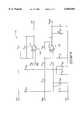
- FIG. 3illustrates a simplified schematic circuit diagram for a rectifier and voltage regulating circuit of control system 40 (of FIG. 2).
- Such circuitrycomprises rectifier 58 and overstroke protection circuitry 84.
- Overstroke protection circuitry 84is engaged whenever an overstroke condition is detected by amplitude detector 50 (of FIG. 2).
- Such circuitryprovides voltage regulation and comprises voltage regulating circuitry. For example, when a battery 70 is provided as useful load 48 (see FIG. 2), the batteries might approach a full charge state which could lead to an overstroke condition. Similarly, if a useful load, such as a battery, is suddenly disconnected which generates a transient load condition such that the load is quickly diminished, an overstroke condition could occur to the power piston.
- Rectifier 58 and overstroke protection circuitry 84are operative so as to generate a controllable load that prevents such overstroke condition.
- Such circuitryis utilized whenever an overstroke condition is generated by a change occurring with an exterior load that is applied to a generator; for example, when such exterior load is quickly and substantially reduced or eliminated. Similarly, any sudden load change would require utilization of overstroke protection to circuitry 84.
- overstroke protection circuitry 84comprises a six-node voltage divider 86 coupled with a Zener diode 88 and an array of operational amplifiers 90 set up as comparators.
- a bank of six resistors 54is provided in conjunction with six associated field effect transistors (FETs) 92, each comprising a switching device.
- FETsfield effect transistors
- Zener diode Z 1 88is sized such that the maximum amplitude for power piston displacement is realized when running such generator at its highest operating amplitude.
- battery charging circuitry 68is tuned in at full power conditions for generator 10 (see FIG. 2).
- a useful load or batteryis disconnected from control circuitry 40 of FIG. 2, then a fully depleted battery bank is connected to control circuitry 40 where it is charged via battery charging circuitry 68.
- Generator 10is then operated at full power, and control circuitry 40 is adjusted until there is no power going to bank of resistors 54. Such adjustment is carried out until voltage divider 86 begins to kick in resistor R 1 , and such adjustment is then backed off until resistor R 1 just goes off.
- operational amplifiers (op amps) 90are set up as comparators. Furthermore, voltage divider 86 compares the voltage drop across resistors R 2 , R 3 , R 4 , R 5 , R 8 and R 52 . As current increases and a voltage drop occurs across each portion of divider 86, the voltage values exceed the respective values of V REF , and a comparator output goes high, turning on each respective FET 92 and respective one of resistors 54.
- Such voltage dividercomprises a ladder circuit that incrementally turns on resistors R 1 , R 41 , R 42 , R 43 , R 44 and R 45 . The turning on of each successive one of resistors 54 by one of FETs 92 causes an incremental increase in loading which is placed upon generator 10.
- V REFprovides an input to op amps 90.
- Each op amp 90forms a comparator that compares such reference voltage with a voltage drop that occurs across the associated ones of resistors R 2 -R 8 and R 52 .
- output from comparator 90goes high, turning on one of FETs 92 and the associated resistor 54.
- FIG. 3also illustrates an input filter 94 configured to clean up power supply for op amps 90.
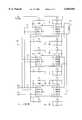
- FIG. 4illustrates voltage regulating circuitry 96 that generates the power supply voltage for op amps 90 (of FIG. 3).
- Such voltage regulating circuitry 96decreases voltage from 110 volts down to 18 volts, in two stages. More particularly, a first stage voltage reduction is implemented by resistors R 60 and R 50 , Zener diode Z 3 , and Q 10 . A second voltage reduction is provided by the remaining circuitry; namely, an off-the-shelf voltage regulator 98 shown as U 7 , diode D 5 , capacitors C 2 and C 4 , and resistors R 7 , R 8 . Such first stage voltage reduction drops 110 volts down to 50 volts. Such second stage voltage reduction drops 50 volts down to 18 volts (18V). Resistor R 9 and Zener diode Z 2 generate reference voltage V REF .
- FIG. 5illustrates a control signal circuit 100 operative to generate a control signal for battery charging circuitry 68 (of FIG. 2). More particularly, a control signal V CON 0 is generated by such control signal circuit 100.
- Control signal V CON 0provides a control signal for the battery charger, or charging circuitry, which tells the battery charger how much current can be drawn off the DC rail without stalling generator 10 (of FIG. 2).
- Resistor R 62is tuned such that control signal V CON 0 is realized such that a maximum level of power is delivered to a battery during a charging operation at a maximum power condition, but without producing overstroke or stalling of a power piston 28 (of FIG. 2).
- resistor R 62enables the production of power output to the batteries without having to enable dumping circuitry (bank of resistors 54 of FIG. 3). In essence, full power is realized and resistor R 62 is adjusted until the dumping circuitry basically stops firing.
- Output signal “OFF”generates an output signal that gives capability for connecting generator 10 and control system 40 (of FIG. 2) with a heater control system (not shown) that controls energy input from heat source 16 (see FIG. 1).
- signal “OFF”is used when running a heater control system. More specifically, a heat source can be shut off via signal “OFF", for example, when a battery is fully charged. Essentially, fuel is shut off when the battery is fully charged in order to save fuel.
- Control signal circuit 100includes a pair of operational amplifiers 102 and 104. According to one implementation, such operational amplifiers are Motorola MC332745 integrated circuits.
- resister R 83provides gain control of the control circuit that generates signal V CON 0.
- control signal V CON 0is delivered to battery charging circuitry 68 (of FIG. 2).
- Such signalenables tuning such that a maximum level of power is delivered to a bank of batteries 70 (of FIG. 2) at a full power operating condition for generator 10 (of FIGS. 1 and 2).
- FIG. 6illustrates battery charging circuitry 68 used in conjunction with battery 70.
- Battery charging circuitry 68includes a plurality of DC/DC converters 106-108. Such converters 106-108 are each controllable such that an output is used to run a load; if the load becomes too great for the generator, such circuitry does not allow the battery charger 68 to pass any more power to the load (or battery).
- Such circuitry 68enables a free-piston Stirling machine, such as an engine or generator, to provide a battery charging function for all potential battery conditions.
- a linear alternatoris protected by preventing an output piston from overstroking during a transient loading condition, or from potentially hazardous operating conditions.
- Such overstroke conditioncan occur when less power is drawn out than is produced by the generator.
- a stalling conditioncan lead to a transient loading condition which might overstroke a moving member, such as the power piston. Accordingly, a stalling condition can generate an overstroke condition which could damage a moving member.
- FIG. 7illustrates another preferred implementation of Applicant's invention wherein controller 40 as depicted with reference to FIGS. 1 and 2, and the implementation circuitry depicted in FIGS. 3-6, are used in combination with a pair of converters, or free-piston Stirling cycle generators 10.
- controller 40as depicted with reference to FIGS. 1 and 2, and the implementation circuitry depicted in FIGS. 3-6, are used in combination with a pair of converters, or free-piston Stirling cycle generators 10.
- each converter 10is connected on the AC power side such that each converter 10 (converter #1 and converter #2) is able to phase lock with each other. If one of converters 10 begins to go out of phase, the other of converters 10 will pull the first converter back into phase.
- converters 10(converter #1 and converter #2) can be configured in assembly such that moving members are provided in opposed relation such that vibrations cancel out.
- the moving piston within each convertercan be configured in opposed relation with the other converter such that dynamic forces generated by respective moving members can
- FIG. 8illustrates yet another implementation of Applicant's invention wherein a pair of converters, or free-piston Stirling generators, 10 are coupled together, as well as controlled by a pair of controllers 40 (controller #1 and controller #2).
- controllers 40controller #1 and controller #2.
- Such implementationis similar to the implementation depicted in FIG. 7. However, redundancy is provided with the addition of an extra controller 40. In the event that one of controllers 40 fails, the other of controllers 40 can be used to run both of converters 10.
- FIG. 9illustrates an exemplary simplified oscilloscope display screen 72 generated by operation of generator 10 via control system 40 of FIGS. 1-6. More particularly, an exemplary DC output voltage 74 is depicted as generated by a voltage divider network along a DC rail. Secondly, a controllable load member enabling signal 76 is depicted corresponding in time with the exemplary DC output voltage 74. Ripple peaks 78 occurring on output voltage 74 are shown as triggering a controllable load member 46 (see FIGS. 1 and 2) switching on bank of resistors 54 (see FIGS. 2 and 3) when a ripple peak 78 is encountered. The switching on of a bank of resistors is indicated as "ON" by reference numeral 80, whereas such bank is indicated as being switched “OFF” by reference numeral 82.
Landscapes
- Engineering & Computer Science (AREA)
- Chemical & Material Sciences (AREA)
- Combustion & Propulsion (AREA)
- Mechanical Engineering (AREA)
- General Engineering & Computer Science (AREA)
- Control Of Eletrric Generators (AREA)
Abstract
Description
Claims (25)
Priority Applications (3)
| Application Number | Priority Date | Filing Date | Title |
|---|---|---|---|
| US09/143,026US6050092A (en) | 1998-08-28 | 1998-08-28 | Stirling cycle generator control system and method for regulating displacement amplitude of moving members |
| AU57832/99AAU5783299A (en) | 1998-08-28 | 1999-08-20 | Stirling cycle generator control system and method for regulating displacement amplitude of moving members |
| PCT/US1999/019249WO2000012866A1 (en) | 1998-08-28 | 1999-08-20 | Stirling cycle generator control system and method for regulating displacement amplitude of moving members |
Applications Claiming Priority (1)
| Application Number | Priority Date | Filing Date | Title |
|---|---|---|---|
| US09/143,026US6050092A (en) | 1998-08-28 | 1998-08-28 | Stirling cycle generator control system and method for regulating displacement amplitude of moving members |
Publications (1)
| Publication Number | Publication Date |
|---|---|
| US6050092Atrue US6050092A (en) | 2000-04-18 |
Family
ID=22502273
Family Applications (1)
| Application Number | Title | Priority Date | Filing Date |
|---|---|---|---|
| US09/143,026Expired - LifetimeUS6050092A (en) | 1998-08-28 | 1998-08-28 | Stirling cycle generator control system and method for regulating displacement amplitude of moving members |
Country Status (3)
| Country | Link |
|---|---|
| US (1) | US6050092A (en) |
| AU (1) | AU5783299A (en) |
| WO (1) | WO2000012866A1 (en) |
Cited By (55)
| Publication number | Priority date | Publication date | Assignee | Title |
|---|---|---|---|---|
| WO2001065100A3 (en)* | 2000-03-02 | 2002-02-07 | New Power Concepts Llc | Auxiliary power unit |
| US20020121816A1 (en)* | 2000-12-15 | 2002-09-05 | Songgang Qiu | Active vibration and balance system for closed cycle thermodynamic machines |
| US20030230440A1 (en)* | 2000-03-02 | 2003-12-18 | Kamen Dean L. | Hybrid electric vehicles using a stirling engine |
| US20040020199A1 (en)* | 2002-08-05 | 2004-02-05 | Yasushi Yamamoto | Stirling engine and actuator |
| US20040055314A1 (en)* | 2000-12-27 | 2004-03-25 | Katsumi Shimizu | Stirling refrigerator and method of controlling operation of the refrigerator |
| US20040195742A1 (en)* | 2003-04-03 | 2004-10-07 | Wood James Gary | Controller for reducing excessive amplitude of oscillation of free piston |
| US20040221576A1 (en)* | 2003-05-08 | 2004-11-11 | Lynch Thomas H. | Thermal cycle engine boost bridge power interface |
| US20050008272A1 (en)* | 2003-07-08 | 2005-01-13 | Prashant Bhat | Method and device for bearing seal pressure relief |
| US20050028520A1 (en)* | 2003-07-02 | 2005-02-10 | Allan Chertok | Free piston Stirling engine control |
| US20050039454A1 (en)* | 2001-12-26 | 2005-02-24 | Katsumi Shimizu | Stirling engine |
| US20050082994A1 (en)* | 2001-12-14 | 2005-04-21 | Songgang Qiu | Active balance system and vibration balanced machine |
| US20050183419A1 (en)* | 2001-06-15 | 2005-08-25 | New Power Concepts Llc | Thermal improvements for an external combustion engine |
| US20050188674A1 (en)* | 2004-02-09 | 2005-09-01 | New Power Concepts Llc | Compression release valve |
| US20050250062A1 (en)* | 2004-05-06 | 2005-11-10 | New Power Concepts Llc | Gaseous fuel burner |
| US20050278967A1 (en)* | 2003-02-19 | 2005-12-22 | Du Plessis Christoffel Johanne | Measuring towel |
| US20060048510A1 (en)* | 2004-08-24 | 2006-03-09 | Infinia Corporation | Double acting thermodynamically resonant free-piston multicylinder stirling system and method |
| US20060119350A1 (en)* | 2004-12-07 | 2006-06-08 | Global Cooling Bv | Apparatus for determining free piston position and an apparatus for controlling free piston position |
| US20070033935A1 (en)* | 2005-08-09 | 2007-02-15 | Carroll Joseph P | Thermal cycle engine with augmented thermal energy input area |
| US20070158947A1 (en)* | 2006-01-06 | 2007-07-12 | Annen Kurt D | System and method for controlling a power generating system |
| US20070158945A1 (en)* | 2006-01-06 | 2007-07-12 | Aerodyne Research, Inc. | System and method for controlling a power generating system |
| US20070261419A1 (en)* | 2006-05-12 | 2007-11-15 | Flir Systems Inc. | Folded cryocooler design |
| US20070261417A1 (en)* | 2006-05-12 | 2007-11-15 | Uri Bin-Nun | Cable drive mechanism for self tuning refrigeration gas expander |
| US20070261418A1 (en)* | 2006-05-12 | 2007-11-15 | Flir Systems Inc. | Miniaturized gas refrigeration device with two or more thermal regenerator sections |
| US20070261407A1 (en)* | 2006-05-12 | 2007-11-15 | Flir Systems Inc. | Cooled infrared sensor assembly with compact configuration |
| US7310945B2 (en) | 2004-02-06 | 2007-12-25 | New Power Concepts Llc | Work-space pressure regulator |
| US20070295201A1 (en)* | 2004-07-05 | 2007-12-27 | Dadd Michael W | Control of Reciprocating Linear Machines |
| US20080047265A1 (en)* | 2004-08-06 | 2008-02-28 | Microgen Energy Limited | Linear Free Piston Stirling Machine |
| US20080256945A1 (en)* | 2004-12-22 | 2008-10-23 | Stephen Charles Welty | Linear Free Piston Stirling Machine |
| WO2008154057A1 (en)* | 2007-06-11 | 2008-12-18 | Sunpower, Inc. | Controller computing a virtual tuning capacitor for controlling a free-piston stirling engine driving a linear alternator |
| US7485977B2 (en) | 2006-01-06 | 2009-02-03 | Aerodyne Research, Inc. | Power generating system |
| US20090039655A1 (en)* | 2007-08-09 | 2009-02-12 | Global Cooling Bv | Resonant stator balancing of free piston machine coupled to linear motor or alternator |
| US20090320830A1 (en)* | 2008-06-27 | 2009-12-31 | The Boeing Company | Solar power device |
| US7654084B2 (en) | 2000-03-02 | 2010-02-02 | New Power Concepts Llc | Metering fuel pump |
| US20100050671A1 (en)* | 2008-08-29 | 2010-03-04 | Paccar Inc | Climate control systems and methods for a hybrid vehicle |
| US20100083653A1 (en)* | 2008-10-03 | 2010-04-08 | Freudenberg-Nok General Partnership | Mass Damper |
| US20100181052A1 (en)* | 2009-01-16 | 2010-07-22 | Dana Canada Corporation | Finned Cylindrical Heat Exchanger |
| US20100180595A1 (en)* | 2008-10-13 | 2010-07-22 | Paul Fraser | Stirling engine systems, apparatus and methods |
| US20100182809A1 (en)* | 2008-10-13 | 2010-07-22 | Matthew John Cullinane | Apparatus, Systems, and Methods for Controlling Energy Converting Devices |
| CN102121419A (en)* | 2010-01-11 | 2011-07-13 | 伍复军 | Rotary type temperature difference power device |
| US8006511B2 (en) | 2007-06-07 | 2011-08-30 | Deka Products Limited Partnership | Water vapor distillation apparatus, method and system |
| US8069676B2 (en) | 2002-11-13 | 2011-12-06 | Deka Products Limited Partnership | Water vapor distillation apparatus, method and system |
| US8282790B2 (en) | 2002-11-13 | 2012-10-09 | Deka Products Limited Partnership | Liquid pumps with hermetically sealed motor rotors |
| US8359877B2 (en) | 2008-08-15 | 2013-01-29 | Deka Products Limited Partnership | Water vending apparatus |
| US8514409B2 (en) | 2010-03-31 | 2013-08-20 | General Electric Company | System for monitoring a relative displacement of components |
| US8511105B2 (en) | 2002-11-13 | 2013-08-20 | Deka Products Limited Partnership | Water vending apparatus |
| US8944155B2 (en) | 2010-07-15 | 2015-02-03 | Dana Canada Corporation | Annular axial flow ribbed heat exchanger |
| US20160298659A1 (en)* | 2013-11-21 | 2016-10-13 | Westport Power Inc. | Detecting end of stroke in a hydraulic motor |
| RU2606979C1 (en)* | 2015-09-30 | 2017-01-10 | Общество с ограниченной ответственностью "Наука-Энерготех" (ООО "Наука-Энерготех") | Method of controlling total ballast load in autonomous multi-modular electric power plant based on stirling engines |
| US9574556B1 (en) | 2008-11-20 | 2017-02-21 | Aerodyne Research, Inc. | Free piston pump and miniature internal combustion engine |
| US20190089225A1 (en)* | 2017-09-20 | 2019-03-21 | Etagen, Inc. | Dc-dc converter in a non-steady system |
| CN114127403A (en)* | 2019-05-21 | 2022-03-01 | 通用电气公司 | Energy conversion apparatus and control system |
| US11826681B2 (en) | 2006-06-30 | 2023-11-28 | Deka Products Limited Partneship | Water vapor distillation apparatus, method and system |
| US11884555B2 (en) | 2007-06-07 | 2024-01-30 | Deka Products Limited Partnership | Water vapor distillation apparatus, method and system |
| US11885760B2 (en) | 2012-07-27 | 2024-01-30 | Deka Products Limited Partnership | Water vapor distillation apparatus, method and system |
| RU2844221C1 (en)* | 2024-12-26 | 2025-07-28 | Общество с ограниченной ответственностью "Наука-Энерготех" | Low-power hybrid source for autonomous power supply |
Families Citing this family (1)
| Publication number | Priority date | Publication date | Assignee | Title |
|---|---|---|---|---|
| NL2003050C2 (en)* | 2009-06-18 | 2010-12-21 | Enatec Micro Cogen B V | STABILIZER. |
Citations (6)
| Publication number | Priority date | Publication date | Assignee | Title |
|---|---|---|---|---|
| US3911284A (en)* | 1972-10-27 | 1975-10-07 | Stephen F Skala | Fuel and vehicle system based on liquid alkali metal |
| US4433279A (en)* | 1981-02-20 | 1984-02-21 | Mechanical Technology Incorporated | Free piston heat engine stability control system |
| US4498295A (en)* | 1982-08-09 | 1985-02-12 | Knoeoes Stellan | Thermal energy transfer system and method |
| US4642547A (en)* | 1985-08-19 | 1987-02-10 | Sunpower, Inc. | Adaptive regulation system for a linear alternator driven by a free-piston stirling engine |
| US5228293A (en)* | 1992-07-06 | 1993-07-20 | Mechanical Technology Inc. | Low temperature solar-to-electric power conversion system |
| US5743091A (en)* | 1996-05-01 | 1998-04-28 | Stirling Technology Company | Heater head and regenerator assemblies for thermal regenerative machines |
- 1998
- 1998-08-28USUS09/143,026patent/US6050092A/ennot_activeExpired - Lifetime
- 1999
- 1999-08-20WOPCT/US1999/019249patent/WO2000012866A1/enactiveApplication Filing
- 1999-08-20AUAU57832/99Apatent/AU5783299A/ennot_activeAbandoned
Patent Citations (6)
| Publication number | Priority date | Publication date | Assignee | Title |
|---|---|---|---|---|
| US3911284A (en)* | 1972-10-27 | 1975-10-07 | Stephen F Skala | Fuel and vehicle system based on liquid alkali metal |
| US4433279A (en)* | 1981-02-20 | 1984-02-21 | Mechanical Technology Incorporated | Free piston heat engine stability control system |
| US4498295A (en)* | 1982-08-09 | 1985-02-12 | Knoeoes Stellan | Thermal energy transfer system and method |
| US4642547A (en)* | 1985-08-19 | 1987-02-10 | Sunpower, Inc. | Adaptive regulation system for a linear alternator driven by a free-piston stirling engine |
| US5228293A (en)* | 1992-07-06 | 1993-07-20 | Mechanical Technology Inc. | Low temperature solar-to-electric power conversion system |
| US5743091A (en)* | 1996-05-01 | 1998-04-28 | Stirling Technology Company | Heater head and regenerator assemblies for thermal regenerative machines |
Cited By (101)
| Publication number | Priority date | Publication date | Assignee | Title |
|---|---|---|---|---|
| US20100269789A1 (en)* | 2000-03-02 | 2010-10-28 | New Power Concepts Llc | Metering fuel pump |
| US6536207B1 (en) | 2000-03-02 | 2003-03-25 | New Power Concepts Llc | Auxiliary power unit |
| US20030230440A1 (en)* | 2000-03-02 | 2003-12-18 | Kamen Dean L. | Hybrid electric vehicles using a stirling engine |
| US20110168467A1 (en)* | 2000-03-02 | 2011-07-14 | New Power Concepts Llc | Hybrid Electric Vehicles Using a Stirling Engine |
| US7654084B2 (en) | 2000-03-02 | 2010-02-02 | New Power Concepts Llc | Metering fuel pump |
| WO2001065100A3 (en)* | 2000-03-02 | 2002-02-07 | New Power Concepts Llc | Auxiliary power unit |
| US20020121816A1 (en)* | 2000-12-15 | 2002-09-05 | Songgang Qiu | Active vibration and balance system for closed cycle thermodynamic machines |
| US6809486B2 (en) | 2000-12-15 | 2004-10-26 | Stirling Technology Company | Active vibration and balance system for closed cycle thermodynamic machines |
| EP1348918A4 (en)* | 2000-12-27 | 2005-09-28 | Sharp Kk | Stirling refrigerator and method of controlling operation of the refrigerator |
| US20040055314A1 (en)* | 2000-12-27 | 2004-03-25 | Katsumi Shimizu | Stirling refrigerator and method of controlling operation of the refrigerator |
| US7121099B2 (en) | 2000-12-27 | 2006-10-17 | Sharp Kabushiki Kaisha | Stirling refrigerator and method of controlling operation of the refrigerator |
| US20050183419A1 (en)* | 2001-06-15 | 2005-08-25 | New Power Concepts Llc | Thermal improvements for an external combustion engine |
| US7308787B2 (en) | 2001-06-15 | 2007-12-18 | New Power Concepts Llc | Thermal improvements for an external combustion engine |
| US20050082994A1 (en)* | 2001-12-14 | 2005-04-21 | Songgang Qiu | Active balance system and vibration balanced machine |
| US6933629B2 (en) | 2001-12-14 | 2005-08-23 | Stirling Technology Company | Active balance system and vibration balanced machine |
| US7257949B2 (en) | 2001-12-26 | 2007-08-21 | Sharp Kabushiki Kaisha | Stirling engine |
| US20050039454A1 (en)* | 2001-12-26 | 2005-02-24 | Katsumi Shimizu | Stirling engine |
| EP1467159A4 (en)* | 2001-12-26 | 2006-06-07 | Sharp Kk | Stirling engine |
| US6843057B2 (en)* | 2002-08-05 | 2005-01-18 | Isuzu Motors Limited | Stirling engine and actuator |
| US20040020199A1 (en)* | 2002-08-05 | 2004-02-05 | Yasushi Yamamoto | Stirling engine and actuator |
| US8069676B2 (en) | 2002-11-13 | 2011-12-06 | Deka Products Limited Partnership | Water vapor distillation apparatus, method and system |
| US8282790B2 (en) | 2002-11-13 | 2012-10-09 | Deka Products Limited Partnership | Liquid pumps with hermetically sealed motor rotors |
| US8511105B2 (en) | 2002-11-13 | 2013-08-20 | Deka Products Limited Partnership | Water vending apparatus |
| US20050278967A1 (en)* | 2003-02-19 | 2005-12-22 | Du Plessis Christoffel Johanne | Measuring towel |
| US20040195742A1 (en)* | 2003-04-03 | 2004-10-07 | Wood James Gary | Controller for reducing excessive amplitude of oscillation of free piston |
| WO2004094860A3 (en)* | 2003-04-03 | 2005-01-27 | Sunpower Inc | Controller for reducing excessive amplitude of oscillation of free piston |
| US6920967B2 (en)* | 2003-04-03 | 2005-07-26 | Sunpower, Inc. | Controller for reducing excessive amplitude of oscillation of free piston |
| US6871495B2 (en)* | 2003-05-08 | 2005-03-29 | The Boeing Company | Thermal cycle engine boost bridge power interface |
| US20040221576A1 (en)* | 2003-05-08 | 2004-11-11 | Lynch Thomas H. | Thermal cycle engine boost bridge power interface |
| US20050028520A1 (en)* | 2003-07-02 | 2005-02-10 | Allan Chertok | Free piston Stirling engine control |
| US7200994B2 (en) | 2003-07-02 | 2007-04-10 | Tiax Llc | Free piston stirling engine control |
| US20050008272A1 (en)* | 2003-07-08 | 2005-01-13 | Prashant Bhat | Method and device for bearing seal pressure relief |
| US7310945B2 (en) | 2004-02-06 | 2007-12-25 | New Power Concepts Llc | Work-space pressure regulator |
| US7007470B2 (en) | 2004-02-09 | 2006-03-07 | New Power Concepts Llc | Compression release valve |
| US20050188674A1 (en)* | 2004-02-09 | 2005-09-01 | New Power Concepts Llc | Compression release valve |
| US20050250062A1 (en)* | 2004-05-06 | 2005-11-10 | New Power Concepts Llc | Gaseous fuel burner |
| US7934926B2 (en) | 2004-05-06 | 2011-05-03 | Deka Products Limited Partnership | Gaseous fuel burner |
| US20070295201A1 (en)* | 2004-07-05 | 2007-12-27 | Dadd Michael W | Control of Reciprocating Linear Machines |
| US7584612B2 (en)* | 2004-08-06 | 2009-09-08 | Microgen Energy Limited | Linear free piston Stirling machine |
| US20080047265A1 (en)* | 2004-08-06 | 2008-02-28 | Microgen Energy Limited | Linear Free Piston Stirling Machine |
| EP1797309A4 (en)* | 2004-08-24 | 2009-12-02 | Infinia Corp | Double acting thermodynamically resonant free-piston multicylinder stirling system and method |
| US7134279B2 (en)* | 2004-08-24 | 2006-11-14 | Infinia Corporation | Double acting thermodynamically resonant free-piston multicylinder stirling system and method |
| US20060048510A1 (en)* | 2004-08-24 | 2006-03-09 | Infinia Corporation | Double acting thermodynamically resonant free-piston multicylinder stirling system and method |
| WO2006023872A3 (en)* | 2004-08-24 | 2006-04-20 | Infinia Corp | Double acting thermodynamically resonant free-piston multicylinder stirling system and method |
| US7075292B2 (en)* | 2004-12-07 | 2006-07-11 | Global Cooling Bv | Apparatus for determining free piston position and an apparatus for controlling free piston position |
| US20060119350A1 (en)* | 2004-12-07 | 2006-06-08 | Global Cooling Bv | Apparatus for determining free piston position and an apparatus for controlling free piston position |
| US20080256945A1 (en)* | 2004-12-22 | 2008-10-23 | Stephen Charles Welty | Linear Free Piston Stirling Machine |
| US7827789B2 (en) | 2004-12-22 | 2010-11-09 | Microgen Energy Limited | Linear free piston stirling machine |
| US20070033935A1 (en)* | 2005-08-09 | 2007-02-15 | Carroll Joseph P | Thermal cycle engine with augmented thermal energy input area |
| US7607299B2 (en) | 2005-08-09 | 2009-10-27 | Pratt & Whitney Rocketdyne, Inc. | Thermal cycle engine with augmented thermal energy input area |
| US20070158945A1 (en)* | 2006-01-06 | 2007-07-12 | Aerodyne Research, Inc. | System and method for controlling a power generating system |
| US7485977B2 (en) | 2006-01-06 | 2009-02-03 | Aerodyne Research, Inc. | Power generating system |
| US7332825B2 (en)* | 2006-01-06 | 2008-02-19 | Aerodyne Research, Inc. | System and method for controlling a power generating system |
| US7629699B2 (en) | 2006-01-06 | 2009-12-08 | Aerodyne Research, Inc. | System and method for controlling a power generating system |
| US20070158947A1 (en)* | 2006-01-06 | 2007-07-12 | Annen Kurt D | System and method for controlling a power generating system |
| US7555908B2 (en) | 2006-05-12 | 2009-07-07 | Flir Systems, Inc. | Cable drive mechanism for self tuning refrigeration gas expander |
| US20070261417A1 (en)* | 2006-05-12 | 2007-11-15 | Uri Bin-Nun | Cable drive mechanism for self tuning refrigeration gas expander |
| US7587896B2 (en) | 2006-05-12 | 2009-09-15 | Flir Systems, Inc. | Cooled infrared sensor assembly with compact configuration |
| US8074457B2 (en) | 2006-05-12 | 2011-12-13 | Flir Systems, Inc. | Folded cryocooler design |
| US8959929B2 (en) | 2006-05-12 | 2015-02-24 | Flir Systems Inc. | Miniaturized gas refrigeration device with two or more thermal regenerator sections |
| US20070261407A1 (en)* | 2006-05-12 | 2007-11-15 | Flir Systems Inc. | Cooled infrared sensor assembly with compact configuration |
| US20070261418A1 (en)* | 2006-05-12 | 2007-11-15 | Flir Systems Inc. | Miniaturized gas refrigeration device with two or more thermal regenerator sections |
| US20070261419A1 (en)* | 2006-05-12 | 2007-11-15 | Flir Systems Inc. | Folded cryocooler design |
| US11826681B2 (en) | 2006-06-30 | 2023-11-28 | Deka Products Limited Partneship | Water vapor distillation apparatus, method and system |
| US11884555B2 (en) | 2007-06-07 | 2024-01-30 | Deka Products Limited Partnership | Water vapor distillation apparatus, method and system |
| US8006511B2 (en) | 2007-06-07 | 2011-08-30 | Deka Products Limited Partnership | Water vapor distillation apparatus, method and system |
| JP2010530041A (en)* | 2007-06-11 | 2010-09-02 | サンパワー・インコーポレーテッド | A controller that calculates a virtual tuning capacitor for controlling a free piston Stirling engine driving a linear alternator. |
| CN102349074B (en)* | 2007-06-11 | 2013-12-04 | 圣波尔股份有限公司 | Calculation of virtual tuning capacitors to control a controller for a free-piston Stirling engine driving a linear generator |
| KR101433732B1 (en) | 2007-06-11 | 2014-08-25 | 썬파워, 인코포레이티드 | Controller computing a virtual tuning capacitor for controlling a free-piston stirling engine driving a linear alternator |
| WO2008154057A1 (en)* | 2007-06-11 | 2008-12-18 | Sunpower, Inc. | Controller computing a virtual tuning capacitor for controlling a free-piston stirling engine driving a linear alternator |
| CN102349074A (en)* | 2007-06-11 | 2012-02-08 | 圣波尔股份有限公司 | Calculation of virtual tuning capacitors to control a controller for a free-piston Stirling engine driving a linear generator |
| JP2009133299A (en)* | 2007-08-09 | 2009-06-18 | Global Cooling Bv | Stator resonance balance means of free piston device connected to linear motor or AC generator |
| US8011183B2 (en)* | 2007-08-09 | 2011-09-06 | Global Cooling Bv | Resonant stator balancing of free piston machine coupled to linear motor or alternator |
| US20090039655A1 (en)* | 2007-08-09 | 2009-02-12 | Global Cooling Bv | Resonant stator balancing of free piston machine coupled to linear motor or alternator |
| US20090320830A1 (en)* | 2008-06-27 | 2009-12-31 | The Boeing Company | Solar power device |
| US8776784B2 (en) | 2008-06-27 | 2014-07-15 | The Boeing Company | Solar power device |
| US11285399B2 (en) | 2008-08-15 | 2022-03-29 | Deka Products Limited Partnership | Water vending apparatus |
| US8359877B2 (en) | 2008-08-15 | 2013-01-29 | Deka Products Limited Partnership | Water vending apparatus |
| US20100050671A1 (en)* | 2008-08-29 | 2010-03-04 | Paccar Inc | Climate control systems and methods for a hybrid vehicle |
| US20100083653A1 (en)* | 2008-10-03 | 2010-04-08 | Freudenberg-Nok General Partnership | Mass Damper |
| US8559197B2 (en) | 2008-10-13 | 2013-10-15 | Infinia Corporation | Electrical control circuits for an energy converting apparatus |
| US20100182809A1 (en)* | 2008-10-13 | 2010-07-22 | Matthew John Cullinane | Apparatus, Systems, and Methods for Controlling Energy Converting Devices |
| US20100180595A1 (en)* | 2008-10-13 | 2010-07-22 | Paul Fraser | Stirling engine systems, apparatus and methods |
| US8869529B2 (en) | 2008-10-13 | 2014-10-28 | Qnergy Inc | Stirling engine systems, apparatus and methods |
| US8151568B2 (en) | 2008-10-13 | 2012-04-10 | Infinia Corporation | Stirling engine systems, apparatus and methods |
| US9574556B1 (en) | 2008-11-20 | 2017-02-21 | Aerodyne Research, Inc. | Free piston pump and miniature internal combustion engine |
| US20100181052A1 (en)* | 2009-01-16 | 2010-07-22 | Dana Canada Corporation | Finned Cylindrical Heat Exchanger |
| US8474515B2 (en) | 2009-01-16 | 2013-07-02 | Dana Canada Corporation | Finned cylindrical heat exchanger |
| CN102121419B (en)* | 2010-01-11 | 2013-12-11 | 伍复军 | Rotary type temperature difference power device |
| CN102121419A (en)* | 2010-01-11 | 2011-07-13 | 伍复军 | Rotary type temperature difference power device |
| US8514409B2 (en) | 2010-03-31 | 2013-08-20 | General Electric Company | System for monitoring a relative displacement of components |
| US8944155B2 (en) | 2010-07-15 | 2015-02-03 | Dana Canada Corporation | Annular axial flow ribbed heat exchanger |
| US11885760B2 (en) | 2012-07-27 | 2024-01-30 | Deka Products Limited Partnership | Water vapor distillation apparatus, method and system |
| US10385890B2 (en)* | 2013-11-21 | 2019-08-20 | Westport Power Inc. | Detecting end of stroke in a hydraulic motor |
| US20160298659A1 (en)* | 2013-11-21 | 2016-10-13 | Westport Power Inc. | Detecting end of stroke in a hydraulic motor |
| RU2606979C1 (en)* | 2015-09-30 | 2017-01-10 | Общество с ограниченной ответственностью "Наука-Энерготех" (ООО "Наука-Энерготех") | Method of controlling total ballast load in autonomous multi-modular electric power plant based on stirling engines |
| US20190089225A1 (en)* | 2017-09-20 | 2019-03-21 | Etagen, Inc. | Dc-dc converter in a non-steady system |
| US10554099B2 (en)* | 2017-09-20 | 2020-02-04 | Etagen, Inc. | DC-DC converter in a non-steady system |
| US10916991B2 (en) | 2017-09-20 | 2021-02-09 | Mainspring Energy, Inc. | DC-DC converter in a non-steady system |
| CN114127403A (en)* | 2019-05-21 | 2022-03-01 | 通用电气公司 | Energy conversion apparatus and control system |
| RU2844221C1 (en)* | 2024-12-26 | 2025-07-28 | Общество с ограниченной ответственностью "Наука-Энерготех" | Low-power hybrid source for autonomous power supply |
Also Published As
| Publication number | Publication date |
|---|---|
| AU5783299A (en) | 2000-03-21 |
| WO2000012866A1 (en) | 2000-03-09 |
Similar Documents
| Publication | Publication Date | Title |
|---|---|---|
| US6050092A (en) | Stirling cycle generator control system and method for regulating displacement amplitude of moving members | |
| RU2216847C2 (en) | Hybrid generating device | |
| EP2083498B1 (en) | An AC power generating system | |
| US4663581A (en) | Voltage regulated permanent magnet generator system | |
| EP1644629B1 (en) | Free piston stirling engine control | |
| US7105938B2 (en) | Electronically controlled engine generator set | |
| US9444391B2 (en) | Protective module and method against torque peaks between a motor and an electric machine | |
| US7705568B2 (en) | Power-generator control apparatus for addressing occurrence of voltage transient | |
| US20060066112A1 (en) | Turbogenerator/motor controller with ancillary energy storage/discharge | |
| EP3068033B1 (en) | Control of hybrid permanent magnet machine with rotating power converter and energy source | |
| CA2949552C (en) | Auxiliary winding for a generator | |
| US20030137196A1 (en) | Power supply for providing continuous and regulated energy to the power user | |
| JPS6277098A (en) | gas turbine generator | |
| US5541483A (en) | Control system and method for controlling a DC motor or generator | |
| WO2025006082A1 (en) | Excitation system for generator | |
| JPH0736472Y2 (en) | Engine generator | |
| JPS6389100A (en) | Voltage regulator of rotary exciting winding of generator | |
| US2474872A (en) | Electrical system | |
| JPS62221880A (en) | Portable engine generator | |
| SU1096516A1 (en) | Transmission testing stand | |
| KR100193425B1 (en) | Voltage regulator and method of voltage regulation of hybrid magnet generator | |
| EP2912765A2 (en) | Dynamo-electric machine | |
| ZA200205882B (en) | An AC power generating system. |
Legal Events
| Date | Code | Title | Description |
|---|---|---|---|
| AS | Assignment | Owner name:STIRLING TECHNOLOGY COMPANY, WASHINGTON Free format text:ASSIGNMENT OF ASSIGNORS INTEREST;ASSIGNORS:GENSTLER, CURTIS;WILLIFORD, IAN;BOBRY, HOWARD H.;REEL/FRAME:009592/0769;SIGNING DATES FROM 19981102 TO 19981110 | |
| STCF | Information on status: patent grant | Free format text:PATENTED CASE | |
| CC | Certificate of correction | ||
| FPAY | Fee payment | Year of fee payment:4 | |
| FPAY | Fee payment | Year of fee payment:8 | |
| AS | Assignment | Owner name:INFINIA CORPORATION (A DELAWARE CORPORATION), WASH Free format text:MERGER AND NAME CHANGE;ASSIGNOR:INFINIA CORPORATION (A WASHINGTON CORPORATION);REEL/FRAME:020638/0417 Effective date:20070608 | |
| AS | Assignment | Owner name:POWER PLAY ENERGY, LLC, AS COLLATERAL AGENT, CONNE Free format text:PATENT SECURITY AGREEMENT;ASSIGNOR:INFINIA CORPORATION;REEL/FRAME:025066/0451 Effective date:20100804 | |
| AS | Assignment | Owner name:POWER PLAY ENERGY, LLC, AS COLLATERAL AGENT, CONNE Free format text:PATENT SECURITY AGREEMENT;ASSIGNOR:INFINIA CORPORATION;REEL/FRAME:026165/0499 Effective date:20110421 | |
| FPAY | Fee payment | Year of fee payment:12 | |
| AS | Assignment | Owner name:INFINIA CORPORATION, UTAH Free format text:RELEASE BY SECURED PARTY;ASSIGNOR:POWER PLAY ENERGY, LLC;REEL/FRAME:030172/0423 Effective date:20130404 | |
| AS | Assignment | Owner name:INFINIA CORPORATION, UTAH Free format text:RELEASE BY SECURED PARTY;ASSIGNOR:POWER PLAY ENERGY, LLC;REEL/FRAME:030544/0390 Effective date:20130411 | |
| AS | Assignment | Owner name:ATLAS GLOBAL INVESTMENT MANAGEMENT LLP, UNITED KIN Free format text:PATENT SECURITY AGREEMENT;ASSIGNOR:INFINIA CORPORATION;REEL/FRAME:030911/0418 Effective date:20130726 | |
| AS | Assignment | Owner name:ATLAS GLOBAL INVESTMENT MANAGEMENT LLP, AS ADMINIS Free format text:SENIOR, SECURED, SUPER-PRIORITY DEBTOR-IN-POSSESSION PATENT SECURITY AGREEMENT;ASSIGNOR:INFINIA CORPORATION;REEL/FRAME:031370/0806 Effective date:20130917 | |
| AS | Assignment | Owner name:RICOR GENERATION INC., ISRAEL Free format text:ASSIGNMENT OF ASSIGNORS INTEREST;ASSIGNOR:INFINIA CORPORATION;REEL/FRAME:031792/0713 Effective date:20131107 Owner name:INFINIA CORPORATION, UTAH Free format text:RELEASE BY SECURED PARTY;ASSIGNOR:ATLAS GLOBAL INVESTMENT MANAGEMENT LLP;REEL/FRAME:031792/0609 Effective date:20131204 | |
| AS | Assignment | Owner name:QNERGY INC, UTAH Free format text:CHANGE OF NAME;ASSIGNOR:RICOR GENERATION INC;REEL/FRAME:032641/0447 Effective date:20131225 |