US6049381A - Real time suspended particle monitor - Google Patents
Real time suspended particle monitorDownload PDFInfo
- Publication number
- US6049381A US6049381AUS08/143,370US14337093AUS6049381AUS 6049381 AUS6049381 AUS 6049381AUS 14337093 AUS14337093 AUS 14337093AUS 6049381 AUS6049381 AUS 6049381A
- Authority
- US
- United States
- Prior art keywords
- image
- fluid
- optical image
- optical
- shapes
- Prior art date
- Legal status (The legal status is an assumption and is not a legal conclusion. Google has not performed a legal analysis and makes no representation as to the accuracy of the status listed.)
- Expired - Lifetime
Links
Images


Classifications
- G—PHYSICS
- G01—MEASURING; TESTING
- G01P—MEASURING LINEAR OR ANGULAR SPEED, ACCELERATION, DECELERATION, OR SHOCK; INDICATING PRESENCE, ABSENCE, OR DIRECTION, OF MOVEMENT
- G01P5/00—Measuring speed of fluids, e.g. of air stream; Measuring speed of bodies relative to fluids, e.g. of ship, of aircraft
- G01P5/001—Full-field flow measurement, e.g. determining flow velocity and direction in a whole region at the same time, flow visualisation
- G—PHYSICS
- G01—MEASURING; TESTING
- G01N—INVESTIGATING OR ANALYSING MATERIALS BY DETERMINING THEIR CHEMICAL OR PHYSICAL PROPERTIES
- G01N15/00—Investigating characteristics of particles; Investigating permeability, pore-volume or surface-area of porous materials
- G01N15/02—Investigating particle size or size distribution
- G01N15/0205—Investigating particle size or size distribution by optical means
- G01N15/0227—Investigating particle size or size distribution by optical means using imaging; using holography
- G—PHYSICS
- G01—MEASURING; TESTING
- G01N—INVESTIGATING OR ANALYSING MATERIALS BY DETERMINING THEIR CHEMICAL OR PHYSICAL PROPERTIES
- G01N15/00—Investigating characteristics of particles; Investigating permeability, pore-volume or surface-area of porous materials
- G01N15/02—Investigating particle size or size distribution
- G01N2015/0294—Particle shape
- G—PHYSICS
- G01—MEASURING; TESTING
- G01N—INVESTIGATING OR ANALYSING MATERIALS BY DETERMINING THEIR CHEMICAL OR PHYSICAL PROPERTIES
- G01N21/00—Investigating or analysing materials by the use of optical means, i.e. using sub-millimetre waves, infrared, visible or ultraviolet light
- G01N21/17—Systems in which incident light is modified in accordance with the properties of the material investigated
- G01N2021/1765—Method using an image detector and processing of image signal
- G01N2021/177—Detector of the video camera type
Definitions
- This inventionrelates to a fluid monitoring apparatus for detecting the presence of and determining the characteristics of particulate matter suspended in a fluid. More specifically, this invention relates to a device for the real time identification of the size and shape of a particle within a fluid by forming an optical image of the fluid and analyzing the image.
- Determination of the quantity, characteristics, and types of particulate matter in fluidsis important for many applications such as monitoring fluids in engines and rotating machinery, industrial quality control, food processing, medical analysis, and observing environmental controls.
- Current devices for monitoring particulate matter in fluidsinvolve various mechanical, electrical, or optical means.
- Purely mechanical meansinvolve collecting particulate matter in suitable traps such as filters, screens, or magnetic plugs. Analysis of the particles is done by removing the traps and examining the collected matter. These devices do not provide for real time monitoring. Electrical based particle monitoring devices are based upon induced currents. By sensing or measuring the change in an electric current, the concentration of electrically conducting or nonconducting particles can be determined. However, this technique is not able to identify the size or shape of the particles. In conventional electrical-mechanical devices, such as electric chip detectors in engines, only electrically conducting particles are detected and the detectors provide no identification on the size or shape of the particles.
- Optical deviceshave been used to determine the concentration, number, or size of particles. However, these devices are limited in their ability to identify the shape of particles. They identify the shape of particles by differentiation based on the degree of sphericity (or asymmetry) of the particles. Such devices illuminate a fluid sample and measure the intensity of the light scattered and/or transmitted at various detectors surrounding the sample. By comparing the intensity measured at the various detectors, a degree of sphericity or an asymmetry factor for the particle is determined. The particles are grouped by this degree of asphericity rather than identified or classified by the shape of the particle.
- the size of the particlesis obtained by comparing the average intensity with a reference intensity or with the difference in intensity for a number of particles with a similar asphericity over time. This method yields information on the size of particles but does not provide real time size and shape identification.
- optical devicesare subject to operating requirements that limit the number and type of applications for which they can be used.
- One such requirementis that the particles be passed one at a time or that the fluid be passed in a small volume through a specific point because the light illuminating the particles is directed to that specific point.
- monitorsthat simply measure the light scattered from a single particle, the determination of symmetry is based upon the distribution of light scattered from a single particle. In such monitors, the symmetry of a particle cannot be accurately determined if two or more particles are illuminated at the same time.
- optical devicesAnother limitation of optical devices results from their sensitivity to air bubbles within the fluid. Entrained air bubbles are only distinguished from other particles by the high degree of sphericity or symmetry of the air bubbles. To remedy this, some devices must be oriented so that the air bubbles float to the top or upper area of the chamber containing the sample and, therefore, are removed from the sensing area of the fluid. Other devices will account for air bubbles by ignoring all highly spherical particles in any analysis of particulate matter.
- Real time human visual inspection of particlescan be accomplished by providing a window through which an individual can view the fluid.
- this methodis limited to fluids flowing at low rates of speed. While using a strobe lamp or pulsed light to create the visual effect of stopping the motion of the particles will allow visual inspections for fluids flowing at higher speeds, these increased speeds are far below those encountered in many applications, for example, the speed at which oil flows in aircraft engines. Additionally, visual inspection is limited to those applications in which the particles are of sufficient size to be viewed by an individual and to those applications in which the fluid is sufficiently transmissive to light of wavelengths which can be seen by humans.
- An optical device which forms an image of the fluidwould be advantageous because it would be able to combine the advantages of visual inspection with the advantages of optical devices. More specifically, by analyzing the image formed, an accurate and real time determination of the size and shape of particles within the fluid can be accomplished. Additionally, devices which are sensitive to a wide range of particle sizes and wavelengths of light can be made.
- An oil debris monitoring systemthat provides real time information on the size and shape of particles within the oil will provide an early warning system for engine failure and can be used to record engine condition to identify when maintenance is needed.
- a systemthat can monitor size, shape, and density of particulate debris in engine oil in real time would be a welcome addition to the art.
- Another object of the present inventionis the provision of a system which will form and analyze an image of a fluid to accurately determine the size and shape of particles within the fluid.
- a further object of the present inventionis the provision of a system that accurately determines the size and shape of particles within a fluid, while distinguishing suspended particles from entrained air bubbles.
- Another object of this inventionis to provide a system which will accurately determine the size and shape of particles, even in the presence of a rapidly flowing fluid by using one or more pulsed light sources to allow imaging with a desired degree of spatial resolution.
- Another object of this inventionis to provide a system which can monitor a large volume of fluid without the need to know or control the position of particles in fluid.
- Yet a further object of this inventionis to provide a system which uses parallel processing, of which a neural network is an example, to analyze an image of a fluid volume to quickly and accurately identify and classify particle shapes within the fluid.
- the inventionconcerns a method and apparatus for the real time monitoring of suspended particulates in a fluid in which the apparatus uses a pulsed light source and collimating optics to direct an optical beam into a fluid chamber through which is passing a fluid to be examined.
- An optical image of the fluid within the fluid chamberis formed responsive to the light, and the image detected.
- the detected imagecontains the necessary information to permit classification of particulates in the fluid according to shape, size, etc.
- the imageis analyzed in situ by dedicated hardware pre-programmed to the task.
- FIG. 1is a schematic diagram illustrating a first embodiment of the present invention
- FIG. 2is a schematic diagram showing a second embodiment
- FIG. 3is a schematic diagram showing a third embodiment
- FIGS. 4A and 4Bshow two embodiments of a detection and image processor
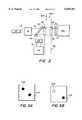
- FIGS. 5A and 5Bshow examples of images of the center of a fluid chamber.
- FIG. 1there is shown a first embodiment of the present invention.
- a fluid 200 to be monitoredpasses through fluid chamber 55.
- Fluid 200either a liquid or a gas, flows in the direction from top to bottom of the sheet in FIG. 1, as indicated by reference arrow 300.
- Source 10emits optical beam 12 into collimating optics 16.
- Optical beam 12 from source 10can be either coherent or noncoherent, depending on the operation and application of the embodiment. Additionally, source 10 can emit beam 12 directly into collimating optics 16 (as shown in FIG. 1) or source 10 can be located some distance away with optical beam 12 directed to collimating optics 16 by conventional means, such as fiber optic cable.
- Collimating optics 16produce a collimated beam 14 which illuminates fluid chamber 55.
- Collimated beam 14preferably has an area such that the entire length, in the direction of the flow of the fluid, of fluid chamber 55 and the entire width, in the direction orthogonal to the sheet in FIG. 1, of fluid chamber 55 is illuminated.
- the collimationcan be accomplished by any of several conventional means including, but not limited to, a lens, a mirror, or a lens and mirror combination.
- the collimating opticscan also include optics for folding the beam to allow the source to be located physically adjacent to the fluid column 50.
- Collimated beam 14propagating in a direction from source 10 toward detector 72, enters fluid chamber 55 such that beam 14 is transverse to, and preferably orthogonal to, the flow of fluid 200.
- Fluid chamber 55has a light transmitting portion 52 allowing collimated beam 14 to enter the fluid chamber and a second light transmitting portion 54 allowing optical beam 14' (the portion of collimated beam 14 transmitted through fluid 200) to exit fluid chamber 55.
- Light transmitting portions 52 and 54 bounding fluid chamber 55should be of sufficient optical quality to allow imaging at the desired degree of spatial resolution.
- Imaging system 20uses optical beam 14' exiting fluid chamber 55 to form an image of fluid 200 within fluid chamber 55.
- the image formed by imaging system 20is carried to optical detector 72 in optical beam 18.
- Optical detector 72is an optically sensitive surface with two dimensional spatial resolution.
- the output of detector 72is connected to shape classifier 74.
- Detector 72converts the image formed on the optically sensitive surface into electronic data.
- This datais transferred to shape classifier 74 which analyzes the output data of detector 72 and identifies the size and shape of a particle in two dimensions based on characteristic patterns (straight lines, corners, curves, etc.).
- shape classifier 74form image processor 60.
- Both optical detector 72 and shape classifier 74can be located some distance from fluid chamber 55 with the image carried to the image processor by conventional means, such as fiber optic cable. A complete description of the operation of image processor 60 is discussed below in reference to FIGS. 4A and 4B.
- source 10is pulsed so a "stop action" image of fluid 200 flowing within chamber 55 can be created.
- a new image of fluid 200 within fluid chamber 55is created onto optical detector 72.
- the imageis analyzed to determine the size and shape of the particles present in the fluid.
- the pulse duration and the pulse repetition rateare chosen with regard to the flow speed of fluid 200.
- the duration of the pulseshould be short enough so that during the pulse the particles do not move by more than the desired spatial resolution. For example, oil flowing through an aircraft engine will flow through a fluid chamber at a maximum rate of 10 m/s. If the desired spatial resolution is 10 microns, the pulse duration should be 1 ⁇ s.
- the repetition rateis set so that, in the time between pulses, fluid 200 travels a distance equal to the length, in the direction of fluid flow, of the fluid imaged, thereby monitoring all the fluid passing through the chamber.
- the time between pulsesshould be 1 ms (the time it takes the oil moving at 10 m/s to travel 1 cm).
- the repetition ratecan be increased to allow the fluid to be imaged more than once as the fluid passes through the fluid chamber.
- source 10must emit optical beam 12 with a wavelength such that the beam can be transmitted through fluid 200 in sufficient quantity to be detectable yet at the same time be absorbed by the particulate matter within the fluid.
- the wavelength of source 10should be greater than 800-nm to allow a sufficient quantity of light to be transmitted through the oil, with a preferred wavelength being between 850 and 1000-nm.
- a single-mode diode laser with a wavelength of 850-nmcan be used to illuminate the oil used in aircraft engines, although any source emitting light with the proper wavelength that is also capable of being pulsed at the proper repetition and duration rates can be used.
- Shape classifier 74can operate with any of a large number of known techniques to classify particulate shape, such as the techniques commonly used for character identification, adapted to specific particulate shapes of interest. Examples of such techniques are: template matching, e.g. two dimensional correlation between the image and a template image; or production of a spatial Fourier transforms of the image, and comparison with a template spectrum.
- the image planeWhen forming the image of fluid 200 onto optical detector 72, the image plane will be at the entrance face of the optical detector, while the object plane will be set based upon the position of the particles. If the position of the particles in fluid 200 within fluid chamber 55 is known or controlled, such as with a narrow fluid chamber, that known position can be used as the object plane by the imaging system. Additionally, when the position of the particles is known or controlled such that the particles will always be in the object plane, either coherent or noncoherent light can be used to illuminate the fluid. If the position of the particles is not known or controlled, imaging system 20 can form an image of fluid 200 using a plane at any position across fluid chamber 55 for the object plane.
- the object planewill be at or near the center of fluid chamber 55 so that the maximum distance from the object plane that particles may be located can be minimized.
- the distanceis minimized because, the closer a particle is to the object plane, the better the resolution of the particle in the image.
- a coherent light sourceis preferred.
- Coherent lightis preferred because it increases the distance from the object plane that particles can be located and yet maintain their shape in an image of the fluid.
- the shape of the particlecan be maintained in an image if coherent light is used and the diffraction pattern is characteristic of the optical near field. Therefore, the shape of a particle at any position across the fluid chamber will be maintained in the image of the fluid chamber if the fluid chamber is illuminated with coherent light and the diffraction pattern of the light exiting the fluid chamber is characteristic of the optical near field.
- Imaging system 20can form either a direct image of the fluid volume or its optical Fourier transform depending upon the requirements of the image processor 60.
- the imagingcan be accomplished by any of several conventional means including, but not limited to, lenses, mirrors, or coherent optical fiber bundles (proximity focusing). If space is limited, imaging system 20 may use mirrors (not shown) to route beam 18 to gain the proper distance needed to focus the image of fluid chamber 55 onto optical detector 72.
- fluid chamber 55can be any size. However, as discussed above, it is preferable that width of fluid chamber 55 be such that the diffraction pattern of the light exiting the fluid chamber is characteristic of the optical near field. Additionally, in selecting length of fluid chamber 55, and the width (in the direction orthogonal to the sheet in FIG. 1) of fluid chamber 55 consideration should be given to the expected size of the particles and the size of the image created.
- FIG. 4Ashows a preferred embodiment of image processor 60.
- Optical beam 18 from the imaging system(not shown) carries the image of the fluid within the fluid chamber to optical detector 72.
- Optical detector 72has an optically sensitive surface containing a two dimensional planar array of opto-electric converters 140 each of which constitutes an image pixel.
- Output 142 of detector 72is connected to shape classifier 74 which analyzes the output of detector 72 and identifies the size and shape of a particle in two dimensions based on characteristic patterns (straight lines, corners, curves, etc.).
- optical detector 72is illuminated by beam 18 for each pulse by the source (as described above in reference to FIG. 1).
- each opto-electric converter 140creates electronic data proportional to the intensity of light from beam 18 received at the converter. Because the electronic data produced at each converter 140 is proportional to the intensity of the light received, variations in the intensity of the image are maintained in the electronic data. Thus, the optical image formed on the face of detector 72 is converted into electronic data that is capable of subsequent electronic reading and processing.
- the dimensions of the image produced and the dimensions of detector 72should correspond to each other. Additionally, to determine the size of a particle within the desired degree of spatial resolution, the distance between the centers of each image pixel (converter) 140 on optical detector 72 should be no larger than the unit of resolution. For instance, if the desired degree of spatial resolution is 10 ⁇ m, the distance between the centers of any two horizontally or vertically adjacent pixels 140 should be less than or equal to 10- ⁇ m.
- optical detectorscan be combined in an array to form a larger optical detector. This arrangement is represented in FIG. 4A by the combination of optical detectors 172, 174, and 176 along with optical detector 72 to form optical detector array 72'.
- the output of each individual detector (72, 172, 174, 176) in the arraywill be connected to shape classifier 74.
- shape classifier 74the image pixels located next to the edge of the detector should be sufficiently close to the edge of the detector such that the distance between the centers of two horizontally or vertically adjacent pixels on neighboring detectors is less than or equal to the desired spatial resolution.
- Converter 140 in detector 72can have an associated charge coupled device (CCD) element which receives a charge proportional to the intensity of light at the converter.
- the CCD elementcan be read to provide an output value corresponding to the charge received at the element.
- the CCD elementscan be read serially providing at output 142 a single string of output values or the CCD's can be read in parallel such that all the CCD elements are read simultaneously providing a plurality of output 142 connections with each individual output 142 containing a single output value from a single CCD.
- converter 140 in detector 72can be a phototransistor. The phototransistor will produce a response, such as a current gain, proportional to the amount of light received. The size of the response produced by the phototransistor can be used to provide an output value corresponding to the intensity of light received at the phototransistor.
- the output 142 from detector 72 comprised of phototransistorscan be read serially or in parallel.
- Shape classifier 74can process the output data from detector 72 using an appropriate pattern recognition or pattern matching technique, such as van der Lugt correlation or Bayesian classification, to determine the size and shape of particles in the fluid. The exact operation of shape classifier 74 will depend upon the type of pattern recognition or pattern matching algorithm chosen of which many types are currently known.
- FIG. 4Bshows an illustration of the embodiment of shape classifier 74.
- shape classifier 74performs a correlation algorithm
- the shape classifierwill typically contain a microprocessor 77 which will use the output data from detector 72 along with information stored in memory means 78 to perform the correlation function.
- the shape classifiercan contain a preprocessor 76 the operation of which will be discussed below.
- the image of the fluidis formed on the face of detector 72.
- the detectorconverts the optical image into electronic data as previously explained.
- the output data from detector 72is sent to shape classifier 74.
- the datais output in parallel, as shown in FIG. 4B, over multiple output connections 142.
- electronic data representing an input image from detector 72is received by shape classifier 74.
- microprocessor 77can perform a correlation algorithm, such as van der Lugt correlation.
- Image correlationis based on the correlation theorem:
- a I and A Rrepresent the input and reference images
- Xdenotes the operation of correlation
- Fdenotes the Fourier transform
- *denotes the complex conjugate.
- preprocessor 76can be used.
- the preprocessorcan be used to perform an intermediate transform, such as a Hough transform, to remove rotational and size dependence. By removing these dependencies, the number of reference images can be reduced thereby reducing the number of correlation products which must be produced.
- preprocessor 76can implement traditional image processing techniques to segment and find areas of the image where particles are represented and to delineate the boundary of such objects. By only passing the data from the input image which contains the image of a particle, the amount of data which is sent to microprocessor 77 for correlation is reduced.
- preprocessor 76can be used to identify certain types or classes of particles which do not need to be identified by size and shape.
- FIG. 2A second embodiment of the present invention is shown in FIG. 2.
- the characteristics, requirements, and operation of elements with reference numerals identical to those in FIG. 1are the same as previously described in reference to FIG. 1.
- source 10provides an optical beam 12 to the collimating optics 16 which produces a collimated beam 14 which is directed toward beam splitter 105.
- Beam splitter 105allows a portion of beam 14 to pass through and continue on in the direction toward fluid chamber 55 while reflecting a portion of beam 14 in a direction away from imaging system 20. The portion of beam 14 directed away from imaging system 20, is lost from the system.
- Collimated beam 14 which has passed through beam splitter 105enters the fluid chamber 55 through window 52, propagates through fluid 200, and exits through window 54. After exiting fluid chamber 55, optical system 22 focuses transmitted beam 14' into phase conjugate reflector 100.
- Phase conjugate reflector 100precisely changes the direction of propagation of the incident beam in such a way that the return beam retraces the same path as the incident beam.
- the return beamtravels back through imaging system 22, entering fluid chamber 55 through window 54 and exiting through window 52.
- the return beamis then split by beam splitter 105 which directs a portion of the return beam toward imaging system 20 while allowing the remaining portion to pass through and continue in the same direction of propagation.
- Imaging system 20forms either a direct image of the center of the fluid chamber or its optical Fourier transform, onto optical detector 72 of image processor 60.
- phase conjugate reflector 100As in the previous embodiment, light source 10 is pulsed so a "stop action" image of fluid 200 flowing through fluid chamber 55 is created at detector 72. Collimated beam 14' transmitted through the chamber is focused onto phase conjugate reflector 100 by optical system 22.
- Optical system 22is placed an arbitrary distance from window 54 or the imaging system can be incorporated into window 54.
- Phase conjugate reflector 100precisely changes the direction of propagation of the incident beam causing the return beam to follow the same path through imaging system 22 and fluid chamber 55 as the incident beam.
- the return beamis directed to imaging system 20 which forms an image of an object plane within fluid 200 onto optical detector 22 in image processor 60.
- This imageis then analyzed by image processor 60.
- image processor 60Once again, a new image of fluid 200 within fluid chamber 55 will be created each time source 10 is pulsed, and therefore, the analysis should be completed in the time between pulses, or in the time between indications by preprocessor 76 that non spherical particulates occur in fluid 200.
- image processor 60is as described above in reference to FIGS. 4A and 4B.
- FIG. 5Ashows an example of an image formed at the optical detector of the device described in reference to FIG. 1.
- the image in FIG. 5Ashows how an air bubble 202 and a nearly spherical particle 204 appear on the face of the optical detector.
- Air bubble 202 in the fluidappears in the image as a dark circle against a bright background due to the scattering of the light by the air bubble.
- Suspended particle 204also appears as a dark shadow against a bright background because the light is absorbed by the particle.
- FIG. 5Bshows how the same image would appear on the optical detector of the embodiment described in FIG. 2.
- air bubble 212appears as a dark ring against a light background while the image of the suspended particle 214 remains a dark shadow.
- the embodiment of FIG. 2allows the application to distinguish air bubbles from spherical particles.
- a third embodiment of the present inventionincorporates two of the devices described in reference to FIG. 1 around a single fluid chamber 55.
- the devices 1 and 3are combined in such a way that the two collimated beams 14 and 34 entering the fluid chamber are essentially orthogonal to each other, as well as to fluid chamber 55.
- the direction of the flow of the fluid (not shown) through the fluid chamber 55can be either into or out of the sheet.
- Sources 10 and 30provide optical beams 12 and 32, respectively.
- the two optical beams 12 and 32are collimated by collimating means 16 and 36, respectively.
- a first collimated beam 14enters fluid chamber 55 through window 52, propagates through the fluid, and exits fluid chamber 55 through window 54.
- Imaging system 20acts on collimated beam 14' that has passed through fluid chamber 55 to form an image with an object plane within fluid chamber 55 onto optical detector 72 of image processor 60.
- a second collimated beam 34enters the fluid chamber 55 through window 57, propagates through the fluid, and exits through window 59.
- Imaging system 40acts on collimated beam 34' exiting fluid chamber 55 to form an image the fluid within fluid chamber 55 onto optical detector 72 of image processor 62.
- Shape processor 90can be used to calculate simple information such as volume of the particle or it can be used to calculate more complex information for three dimensions to further classify particle types such as flakes, crystallites or cubes.
- the characteristics, operation, and requirements of sources 10 and 30, collimating optics 16 and 36, fluid chamber 55, windows 52, 54, 57, and 59, and imaging systems 20 and 40are as previously described in reference to FIG. 1.
- sources 10 and 30are pulsed simultaneously with the pulse duration and pulse repetition rate chosen with regard to the flow speed of the fluid.
- the duration of the pulseshould be short enough so that during the pulse the particles do not move by more than the desired spatial resolution.
- the repetition rateis set so that, in the time between pulses, the fluid travels a distance equal to the length, in the direction of fluid flow, of the fluid imaged.
- the wavelength of each sourcemust be such that the light can be transmitted through the fluid in sufficient quantity to be detectable yet at the same time be absorbed by the particulate matter within the fluid. However, the wavelengths of the sources need not be identical.
- image processors 60 and 62The operation of image processors 60 and 62 is as described above in reference to FIG. 4A. Additionally, data from image processors 60 and 62, containing information on the size, shape, and position of the particles in two dimensions, should be combined together in a shape processor 90 to obtain size and shape information for three dimensions.
- FIG. 3While the embodiment of the present invention shown in FIG. 3 combines two of the devices in FIG. 1 around a single fluid chamber 55, it is also possible to combine three or more of the devices shown in FIG. 1 around a single fluid chamber to obtain more detailed information. Additionally, another variation can be had by combining two or more of the devices of FIG. 2 around a single fluid chamber.
Landscapes
- Chemical & Material Sciences (AREA)
- General Physics & Mathematics (AREA)
- Physics & Mathematics (AREA)
- Biochemistry (AREA)
- Life Sciences & Earth Sciences (AREA)
- Analytical Chemistry (AREA)
- Health & Medical Sciences (AREA)
- General Health & Medical Sciences (AREA)
- Dispersion Chemistry (AREA)
- Immunology (AREA)
- Pathology (AREA)
- Engineering & Computer Science (AREA)
- Aviation & Aerospace Engineering (AREA)
- Investigating Or Analysing Materials By Optical Means (AREA)
Abstract
Description
A.sub.I (x,y)XA.sub.R (x,y)=F.sup.-1 [F(A.sub.I (x,y))F*(A.sub.R (x,y))]
Claims (34)
Priority Applications (5)
| Application Number | Priority Date | Filing Date | Title |
|---|---|---|---|
| US08/143,370US6049381A (en) | 1993-10-29 | 1993-10-29 | Real time suspended particle monitor |
| PCT/US1994/012640WO1995012118A1 (en) | 1993-10-29 | 1994-10-31 | Real time suspended particle monitor |
| CA002174946ACA2174946C (en) | 1993-10-29 | 1994-10-31 | Real time suspended particle monitor |
| AU11299/95AAU1129995A (en) | 1993-10-29 | 1994-10-31 | Real time suspended particle monitor |
| EP95902428AEP0725927A4 (en) | 1993-10-29 | 1994-10-31 | DEVICE FOR REAL-TIME MONITORING OF SUSPENSION PARTICLES |
Applications Claiming Priority (1)
| Application Number | Priority Date | Filing Date | Title |
|---|---|---|---|
| US08/143,370US6049381A (en) | 1993-10-29 | 1993-10-29 | Real time suspended particle monitor |
Publications (1)
| Publication Number | Publication Date |
|---|---|
| US6049381Atrue US6049381A (en) | 2000-04-11 |
Family
ID=22503778
Family Applications (1)
| Application Number | Title | Priority Date | Filing Date |
|---|---|---|---|
| US08/143,370Expired - LifetimeUS6049381A (en) | 1993-10-29 | 1993-10-29 | Real time suspended particle monitor |
Country Status (5)
| Country | Link |
|---|---|
| US (1) | US6049381A (en) |
| EP (1) | EP0725927A4 (en) |
| AU (1) | AU1129995A (en) |
| CA (1) | CA2174946C (en) |
| WO (1) | WO1995012118A1 (en) |
Cited By (73)
| Publication number | Priority date | Publication date | Assignee | Title |
|---|---|---|---|---|
| US20020148788A1 (en)* | 2001-04-17 | 2002-10-17 | Berns Daniel D. | Contamination control for engines |
| US20040165185A1 (en)* | 2002-12-20 | 2004-08-26 | Reintjes John F. | Fluid particle monitor and methods related thereto |
| US20040189991A1 (en)* | 2003-03-27 | 2004-09-30 | J.M. Canty Inc. | Rocksizer |
| US20050134845A1 (en)* | 2003-12-19 | 2005-06-23 | Core Laboratories Lp | Method and apparatus for determining characteristics of particles in a fluid sample |
| US20070041613A1 (en)* | 2005-05-11 | 2007-02-22 | Luc Perron | Database of target objects suitable for use in screening receptacles or people and method and apparatus for generating same |
| WO2007060127A3 (en)* | 2005-11-23 | 2007-08-23 | Basf Ag | Device and method for automatically determining the individual three-dimensional shape of particles |
| US20080143828A1 (en)* | 2006-12-15 | 2008-06-19 | Pollack Laboratories, Inc. | Vision analysis system for a process vessel |
| US20080166037A1 (en)* | 2007-01-08 | 2008-07-10 | Pollack Laboratories, Inc. | Image Recognition and Analysis System and Software |
| US7430322B1 (en)* | 2005-05-02 | 2008-09-30 | Nanostellar, Inc. | Particle shape characterization from 2D images |
| US7561756B1 (en) | 2005-05-02 | 2009-07-14 | Nanostellar, Inc. | Particle shape characterization from 2D images |
| US20090211379A1 (en)* | 2008-02-26 | 2009-08-27 | The Government Of The Us, As Represented By The Secretary Of The Navy | Method and Apparatus for Fluid Sampling |
| US7734102B2 (en) | 2005-05-11 | 2010-06-08 | Optosecurity Inc. | Method and system for screening cargo containers |
| US7899232B2 (en) | 2006-05-11 | 2011-03-01 | Optosecurity Inc. | Method and apparatus for providing threat image projection (TIP) in a luggage screening system, and luggage screening system implementing same |
| DE102009051220A1 (en)* | 2009-10-29 | 2011-06-16 | Krause, Sven, Dr.-Ing. | Device for analyzing fluid i.e. oil, of internal combustion engines, has classifier classifying data originating from another classifier, with respect to error rates, and outputting output signal during exceedance of limits for error rates |
| US20110157351A1 (en)* | 2009-12-31 | 2011-06-30 | Pollack Laboratories, Inc. | Apparatus and Method for Analyzing Fluids in Vessels and Pipelines |
| US7991242B2 (en) | 2005-05-11 | 2011-08-02 | Optosecurity Inc. | Apparatus, method and system for screening receptacles and persons, having image distortion correction functionality |
| US20110224917A1 (en)* | 2010-03-12 | 2011-09-15 | Honeywell International Inc. | Method and system for detecting incipient bearing failures |
| US20130096770A1 (en)* | 2010-04-20 | 2013-04-18 | Airbus Operations Gmbh | Device and method for determining the state of ageing of a hydraulic fluid of a hydraulic system of a vehicle |
| US8494210B2 (en) | 2007-03-30 | 2013-07-23 | Optosecurity Inc. | User interface for use in security screening providing image enhancement capabilities and apparatus for implementing same |
| WO2013164468A1 (en)* | 2012-05-03 | 2013-11-07 | Fras Technology | Fluid analysis |
| WO2013192272A1 (en) | 2012-06-19 | 2013-12-27 | The Government Of The United States Of America, As Represented By The Secretary Of The Navy | Remote multisensor optical particle monitor for flowing fluid systems |
| US8622979B2 (en) | 2010-10-19 | 2014-01-07 | Baxter Healthcare S.A. | Infusion system using optical imager for controlling flow and method thereof |
| WO2014031900A1 (en)* | 2012-08-23 | 2014-02-27 | The Regents Of The University Of California | Fluidic flow cytometry devices and methods |
| WO2014205382A1 (en) | 2013-06-21 | 2014-12-24 | The Government Of The United States Of America, As Represented By The Secretary Of The Navy | Method and apparatus for separation of components of differing buoyancy mixed into a flowing fluid |
| US9128051B2 (en) | 2010-10-19 | 2015-09-08 | Baxter International Inc. | Optical imaging system for air bubble and empty bag detection in an infusion tube |
| US9144644B2 (en) | 2011-08-02 | 2015-09-29 | Baxter International Inc. | Infusion pump with independently controllable valves and low power operation and methods thereof |
| US9151646B2 (en) | 2011-12-21 | 2015-10-06 | Deka Products Limited Partnership | System, method, and apparatus for monitoring, regulating, or controlling fluid flow |
| US9205845B2 (en) | 2012-06-07 | 2015-12-08 | Honeywell International Inc. | System and method for detecting spall initiation and defining end of life in engine components |
| USD745661S1 (en) | 2013-11-06 | 2015-12-15 | Deka Products Limited Partnership | Apparatus to control fluid flow through a tube |
| CN105181537A (en)* | 2015-09-30 | 2015-12-23 | 丹东百特仪器有限公司 | Online laser particle size monitoring system and control method thereof |
| US9234850B2 (en) | 2013-03-14 | 2016-01-12 | Baxter International Inc. | Drip chamber with integrated optics |
| USD749206S1 (en) | 2013-11-06 | 2016-02-09 | Deka Products Limited Partnership | Apparatus to control fluid flow through a tube |
| US9274041B2 (en) | 2014-04-15 | 2016-03-01 | Spectro Scientific, Inc. | Particle counter and classification system |
| USD751689S1 (en) | 2013-11-06 | 2016-03-15 | Deka Products Limited Partnership | Apparatus to control fluid flow through a tube |
| USD751690S1 (en) | 2013-11-06 | 2016-03-15 | Deka Products Limited Partnership | Apparatus to control fluid flow through a tube |
| USD752209S1 (en) | 2013-11-06 | 2016-03-22 | Deka Products Limited Partnership | Apparatus to control fluid flow through a tube |
| DE102008064666B4 (en)* | 2008-09-15 | 2016-03-24 | Fritsch Gmbh | Particle size analyzer |
| US9352081B2 (en) | 2013-03-14 | 2016-05-31 | Baxter International Inc. | Drip chamber with hydrophobic interior surface |
| US9372486B2 (en) | 2011-12-21 | 2016-06-21 | Deka Products Limited Partnership | System, method, and apparatus for monitoring, regulating, or controlling fluid flow |
| US9435455B2 (en) | 2011-12-21 | 2016-09-06 | Deka Products Limited Partnership | System, method, and apparatus for monitoring, regulating, or controlling fluid flow |
| US20160263588A1 (en)* | 2013-06-21 | 2016-09-15 | The Government Of The United States Of America, As Represented By The Secretary Of The Navy | Cascaded Axial Fluid Separator Methods and Systems |
| US9476825B2 (en) | 2010-10-19 | 2016-10-25 | Baxter International Inc. | Optical imaging system with multiple imaging channel optical sensing |
| US9541492B2 (en) | 2014-05-30 | 2017-01-10 | The United States Of America, As Represented By The Secretary Of The Navy | Method and apparatus for stabilizing the thickness of an optical channel for extended pressure environments |
| US9632206B2 (en) | 2011-09-07 | 2017-04-25 | Rapiscan Systems, Inc. | X-ray inspection system that integrates manifest data with imaging/detection processing |
| US9645010B2 (en) | 2009-03-10 | 2017-05-09 | The Regents Of The University Of California | Fluidic flow cytometry devices and methods |
| US9724466B2 (en) | 2011-12-21 | 2017-08-08 | Deka Products Limited Partnership | Flow meter |
| US9746094B2 (en) | 2011-12-21 | 2017-08-29 | Deka Products Limited Partnership | Flow meter having a background pattern with first and second portions |
| US9746093B2 (en) | 2011-12-21 | 2017-08-29 | Deka Products Limited Partnership | Flow meter and related system and apparatus |
| US9759343B2 (en) | 2012-12-21 | 2017-09-12 | Deka Products Limited Partnership | Flow meter using a dynamic background image |
| US9778164B2 (en) | 2009-03-10 | 2017-10-03 | The Regents Of The University Of California | Fluidic flow cytometry devices and particle sensing based on signal-encoding |
| JPWO2017043623A1 (en)* | 2015-09-09 | 2018-03-15 | 株式会社村田製作所 | Drop detection device |
| US10024819B2 (en) | 2010-10-21 | 2018-07-17 | The Regents Of The University Of California | Microfluidics with wirelessly powered electronic circuits |
| US10228683B2 (en) | 2011-12-21 | 2019-03-12 | Deka Products Limited Partnership | System, method, and apparatus for monitoring, regulating, or controlling fluid flow |
| US10302807B2 (en) | 2016-02-22 | 2019-05-28 | Rapiscan Systems, Inc. | Systems and methods for detecting threats and contraband in cargo |
| US20190187036A1 (en)* | 2017-12-18 | 2019-06-20 | Spectro Scientific, Inc. | Particle counter and classification system |
| USD854145S1 (en) | 2016-05-25 | 2019-07-16 | Deka Products Limited Partnership | Apparatus to control fluid flow through a tube |
| EP3447473A3 (en)* | 2017-08-23 | 2019-08-07 | Markus Klotz | Particle sensor |
| US10386284B2 (en)* | 2016-01-29 | 2019-08-20 | JianFeng Zhang | Device and method for measurement of dispersed objects using fluorescent and non-fluorescent imaging with laser |
| US10488848B2 (en) | 2011-12-21 | 2019-11-26 | Deka Products Limited Partnership | System, method, and apparatus for monitoring, regulating, or controlling fluid flow |
| EP3647766A1 (en)* | 2018-10-29 | 2020-05-06 | Hsiu-An Lin | Device for instantaneously inspecting waste quality and recycling device and method using the same |
| US10816550B2 (en) | 2012-10-15 | 2020-10-27 | Nanocellect Biomedical, Inc. | Systems, apparatus, and methods for sorting particles |
| CN111855504A (en)* | 2019-04-26 | 2020-10-30 | 霍尼韦尔国际公司 | Flow device and associated method and system |
| USD905848S1 (en) | 2016-01-28 | 2020-12-22 | Deka Products Limited Partnership | Apparatus to control fluid flow through a tube |
| USD964563S1 (en) | 2019-07-26 | 2022-09-20 | Deka Products Limited Partnership | Medical flow clamp |
| JP2023072668A (en)* | 2021-11-12 | 2023-05-24 | 邑流微測股▲ふん▼有限公司 | optical imaging system |
| US11744935B2 (en) | 2016-01-28 | 2023-09-05 | Deka Products Limited Partnership | Apparatus for monitoring, regulating, or controlling fluid flow |
| DE102022113774A1 (en) | 2022-05-31 | 2023-11-30 | CiS Forschungsinstitut für Mikrosensorik GmbH | Particle sensor and method for detecting particles |
| US11839741B2 (en) | 2019-07-26 | 2023-12-12 | Deka Products Limited Partneship | Apparatus for monitoring, regulating, or controlling fluid flow |
| US11940451B2 (en) | 2021-12-20 | 2024-03-26 | Instrumentation Laboratory Co. | Microfluidic image analysis system |
| US12098738B2 (en) | 2011-12-21 | 2024-09-24 | Deka Products Limited Partnership | System, method, and apparatus for clamping |
| US12111257B2 (en) | 2020-08-26 | 2024-10-08 | Honeywell International Inc. | Fluid composition sensor device and method of using the same |
| US12181400B2 (en) | 2020-02-14 | 2024-12-31 | Honeywell International Inc. | Fluid composition sensor device and method of using the same |
| US12209941B2 (en) | 2020-10-26 | 2025-01-28 | Honeywell International Inc. | Fluid composition sensor device and method of using the same |
Families Citing this family (16)
| Publication number | Priority date | Publication date | Assignee | Title |
|---|---|---|---|---|
| DE19720426C1 (en)* | 1997-05-15 | 1999-06-02 | Baier Verena Dr Ing | Optical measuring device for particles suspended in transparent fluid |
| US6104483A (en)* | 1999-06-18 | 2000-08-15 | Lockheed Martin Tactical Defense Systems, Inc. | Optical flow cell with references flange |
| GB9916932D0 (en)* | 1999-07-16 | 1999-09-22 | Funes Gallanzi Marcelo | Method and apparatus for investigating fluid flow variables element characteristics and near-surface temperature and forces |
| FR2807522B1 (en)* | 2000-04-07 | 2002-06-14 | Aerospatiale Matra Airbus | DEVICE FOR DETERMINING THE VALUES OF AT LEAST ONE PARAMETER OF PARTICLES, ESPECIALLY WATER DROPLETS |
| NL1015640C2 (en)* | 2000-07-06 | 2002-01-08 | Univ Delft Tech | Device and method for determining the shape and / or size of small particles. |
| US6873411B2 (en) | 2001-08-07 | 2005-03-29 | Lockheed Martin Corporation | Optical debris analysis fixture |
| US7019834B2 (en) | 2002-06-04 | 2006-03-28 | Lockheed Martin Corporation | Tribological debris analysis system |
| US7385694B2 (en) | 2002-06-04 | 2008-06-10 | Lockheed Martin Corporation | Tribological debris analysis system |
| US7184141B2 (en) | 2004-03-23 | 2007-02-27 | Lockheed Martin Corporation | Optical flow cell for tribological systems |
| US7307717B2 (en) | 2005-09-16 | 2007-12-11 | Lockheed Martin Corporation | Optical flow cell capable of use in high temperature and high pressure environment |
| US8018237B2 (en)* | 2006-09-26 | 2011-09-13 | Ntn Corporation | Broken piece detecting sensor |
| US7927479B2 (en)* | 2006-12-20 | 2011-04-19 | Exxonmobil Research And Engineering Company | Focused beam reflectance measurement to optimize desalter performance and reduce downstream fouling |
| EP1944601A1 (en)* | 2007-01-09 | 2008-07-16 | STMicroelectronics (Research & Development) Limited | Optical fluid assessment apparatus |
| US7518720B2 (en) | 2007-08-01 | 2009-04-14 | Lockheed Martin Corporation | Optical flow cell for use in high temperature and/or high pressure environments |
| US8079250B2 (en) | 2008-07-09 | 2011-12-20 | Lockheed Martin Corporation | Viscometer system utilizing an optical flow cell |
| US20100163461A1 (en)* | 2008-10-09 | 2010-07-01 | Wright Chris A | Method and system for controlling the amount of anti-fouling additive for particulate-induced fouling mitigation in refining operations |
Citations (18)
| Publication number | Priority date | Publication date | Assignee | Title |
|---|---|---|---|---|
| US3641320A (en)* | 1970-12-23 | 1972-02-08 | Us Air Force | Raindrop counter |
| US4288162A (en)* | 1979-02-27 | 1981-09-08 | Sumitomo Kinzoku Kogyo Kabushiki Kaisha | Measuring particle size distribution |
| US4329052A (en)* | 1977-08-01 | 1982-05-11 | Mobil Oil Corporation | Method and apparatus for the measurement of cell size in a foam structure |
| US4393466A (en)* | 1980-09-12 | 1983-07-12 | International Remote Imaging Systems | Method of analyzing particles in a dilute fluid sample |
| JPS59107201A (en)* | 1982-12-13 | 1984-06-21 | Hitachi Ltd | Foreign matter measurement device in fluid |
| US4805225A (en)* | 1986-11-06 | 1989-02-14 | The Research Foundation Of The State University Of New York | Pattern recognition method and apparatus |
| US4804267A (en)* | 1986-07-10 | 1989-02-14 | Scientific Imaging Instruments, Inc. | System for microscopically analyzing fluids |
| US4981362A (en)* | 1989-10-16 | 1991-01-01 | Xerox Corporation | Particle concentration measuring method and device |
| US4999513A (en)* | 1988-09-09 | 1991-03-12 | Canon Kabushiki Kaisha | Particle measuring apparatus |
| US5011285A (en)* | 1987-12-18 | 1991-04-30 | Norsk Hydro A.S. | Method and apparatus for performing automatic particle analysis |
| US5089714A (en)* | 1987-11-10 | 1992-02-18 | The Secretary Of State For Defence In Her Britannic Majesty's Government Of The United Kingdom Of Great Britain And Northern Ireland | Particle asymmetry analyzer having sphericity detectors |
| US5140168A (en)* | 1990-12-03 | 1992-08-18 | Great Lakes Instruments, Inc. | Turbidimeter signal processing circuit using alternating light sources |
| US5141324A (en)* | 1990-12-26 | 1992-08-25 | Stranco, Inc. | Visual monitoring device for sludge conditioning system |
| US5150229A (en)* | 1988-09-07 | 1992-09-22 | Seiko Instruments Inc. | Optical correlator |
| US5150228A (en)* | 1991-11-25 | 1992-09-22 | The United States Of America As Represented By The Administrator Of The National Aeronautics And Space Administration | Real-time edge-enhanced optical correlator |
| EP0507746A2 (en)* | 1991-04-03 | 1992-10-07 | Istituto Nazionale Di Ottica | Method and device for measuring the particle size distribution of a flowing solid particulate substance |
| JPH0545274A (en)* | 1991-08-13 | 1993-02-23 | Res Dev Corp Of Japan | Particle measuring device |
| US5191388A (en)* | 1991-12-18 | 1993-03-02 | Flow Vision, Inc. | Apparatus for detecting and analyzing particulate matter in a slurry flow |
Family Cites Families (5)
| Publication number | Priority date | Publication date | Assignee | Title |
|---|---|---|---|---|
| GB1430420A (en)* | 1972-04-24 | 1976-03-31 | Niemi A | Method and apparatus for analyzing a visible object |
| US3769633A (en)* | 1972-05-11 | 1973-10-30 | Us Navy | Raindrop image recording analyzer system |
| JPS61139746A (en)* | 1984-12-13 | 1986-06-27 | Diesel Kiki Co Ltd | Apparatus for judging spray pattern |
| GB8623072D0 (en)* | 1986-09-25 | 1986-10-29 | Amersham Int Plc | Particle analysis |
| WO1993017322A1 (en)* | 1992-02-21 | 1993-09-02 | Secretary Of State For Defence In Her | Analysis of particle characteristics |
- 1993
- 1993-10-29USUS08/143,370patent/US6049381A/ennot_activeExpired - Lifetime
- 1994
- 1994-10-31AUAU11299/95Apatent/AU1129995A/ennot_activeAbandoned
- 1994-10-31WOPCT/US1994/012640patent/WO1995012118A1/enactiveApplication Filing
- 1994-10-31EPEP95902428Apatent/EP0725927A4/ennot_activeWithdrawn
- 1994-10-31CACA002174946Apatent/CA2174946C/ennot_activeExpired - Fee Related
Patent Citations (18)
| Publication number | Priority date | Publication date | Assignee | Title |
|---|---|---|---|---|
| US3641320A (en)* | 1970-12-23 | 1972-02-08 | Us Air Force | Raindrop counter |
| US4329052A (en)* | 1977-08-01 | 1982-05-11 | Mobil Oil Corporation | Method and apparatus for the measurement of cell size in a foam structure |
| US4288162A (en)* | 1979-02-27 | 1981-09-08 | Sumitomo Kinzoku Kogyo Kabushiki Kaisha | Measuring particle size distribution |
| US4393466A (en)* | 1980-09-12 | 1983-07-12 | International Remote Imaging Systems | Method of analyzing particles in a dilute fluid sample |
| JPS59107201A (en)* | 1982-12-13 | 1984-06-21 | Hitachi Ltd | Foreign matter measurement device in fluid |
| US4804267A (en)* | 1986-07-10 | 1989-02-14 | Scientific Imaging Instruments, Inc. | System for microscopically analyzing fluids |
| US4805225A (en)* | 1986-11-06 | 1989-02-14 | The Research Foundation Of The State University Of New York | Pattern recognition method and apparatus |
| US5089714A (en)* | 1987-11-10 | 1992-02-18 | The Secretary Of State For Defence In Her Britannic Majesty's Government Of The United Kingdom Of Great Britain And Northern Ireland | Particle asymmetry analyzer having sphericity detectors |
| US5011285A (en)* | 1987-12-18 | 1991-04-30 | Norsk Hydro A.S. | Method and apparatus for performing automatic particle analysis |
| US5150229A (en)* | 1988-09-07 | 1992-09-22 | Seiko Instruments Inc. | Optical correlator |
| US4999513A (en)* | 1988-09-09 | 1991-03-12 | Canon Kabushiki Kaisha | Particle measuring apparatus |
| US4981362A (en)* | 1989-10-16 | 1991-01-01 | Xerox Corporation | Particle concentration measuring method and device |
| US5140168A (en)* | 1990-12-03 | 1992-08-18 | Great Lakes Instruments, Inc. | Turbidimeter signal processing circuit using alternating light sources |
| US5141324A (en)* | 1990-12-26 | 1992-08-25 | Stranco, Inc. | Visual monitoring device for sludge conditioning system |
| EP0507746A2 (en)* | 1991-04-03 | 1992-10-07 | Istituto Nazionale Di Ottica | Method and device for measuring the particle size distribution of a flowing solid particulate substance |
| JPH0545274A (en)* | 1991-08-13 | 1993-02-23 | Res Dev Corp Of Japan | Particle measuring device |
| US5150228A (en)* | 1991-11-25 | 1992-09-22 | The United States Of America As Represented By The Administrator Of The National Aeronautics And Space Administration | Real-time edge-enhanced optical correlator |
| US5191388A (en)* | 1991-12-18 | 1993-03-02 | Flow Vision, Inc. | Apparatus for detecting and analyzing particulate matter in a slurry flow |
Non-Patent Citations (11)
| Title |
|---|
| Casasent, "An Optical Correlator Feature Extractor Neural Net System", Optical Engineering, vol. 31, No. 5, May 1992, pp. 971-978. |
| Casasent, An Optical Correlator Feature Extractor Neural Net System , Optical Engineering, vol. 31, No. 5, May 1992, pp. 971 978.* |
| Intel News Release, Intel and Nestor Deliver Second Generation Neural Network Chip to DARPA, Feb. 12, 1993.* |
| Intel News Release, Intel and Nestor Deliver Second-Generation Neural Network Chip to DARPA, Feb. 12, 1993. |
| Intel/Nestor, Preliminary Information Ni1000 Recognition Accelerator, Apr. 1993.* |
| Liu et al., "Real-Time VanderLugt Optical Correlator the Uses Photorefractive GaAs", Applied Optics, vol. 31, No. 26, Sep. 10, 1992, pp. 5675-5680. |
| Liu et al., Real Time VanderLugt Optical Correlator the Uses Photorefractive GaAs , Applied Optics, vol. 31, No. 26, Sep. 10, 1992, pp. 5675 5680.* |
| Nicholson et al., "Optimization of an Updatable Optical Image Correlator", Optical Engineering, vol. 26, No. 5, May 1987, pp. 445-452. |
| Nicholson et al., Optimization of an Updatable Optical Image Correlator , Optical Engineering, vol. 26, No. 5, May 1987, pp. 445 452.* |
| Rajbenbach et al., "Compact Photorefractive Correlator for Robotic Applicons", Applied Optics, vol. 31, No. 26, Sep. 10, 1992, pp. 5666-5674. |
| Rajbenbach et al., Compact Photorefractive Correlator for Robotic Applications , Applied Optics, vol. 31, No. 26, Sep. 10, 1992, pp. 5666 5674.* |
Cited By (155)
| Publication number | Priority date | Publication date | Assignee | Title |
|---|---|---|---|---|
| US6966994B2 (en)* | 2001-04-17 | 2005-11-22 | Caterpillar Inc | Contamination control for engines |
| US20020148788A1 (en)* | 2001-04-17 | 2002-10-17 | Berns Daniel D. | Contamination control for engines |
| US7921739B2 (en) | 2002-12-20 | 2011-04-12 | Fjerdingstad Soelve J | In situ sampling and monitoring a fluid |
| US20040165185A1 (en)* | 2002-12-20 | 2004-08-26 | Reintjes John F. | Fluid particle monitor and methods related thereto |
| US20040189991A1 (en)* | 2003-03-27 | 2004-09-30 | J.M. Canty Inc. | Rocksizer |
| US7009703B2 (en)* | 2003-03-27 | 2006-03-07 | J.M.Canty Inc. | Granular product inspection device |
| US20050134845A1 (en)* | 2003-12-19 | 2005-06-23 | Core Laboratories Lp | Method and apparatus for determining characteristics of particles in a fluid sample |
| US7079242B2 (en)* | 2003-12-19 | 2006-07-18 | Core Laboratories L.P. | Method and apparatus for determining characteristics of particles in a fluid sample |
| US20070035738A1 (en)* | 2003-12-19 | 2007-02-15 | Core Laboratories Lp | Method and apparatus for determining characteristics of particles in a fluid sample |
| US7542139B2 (en)* | 2003-12-19 | 2009-06-02 | Core Laboratories Lp | Method and apparatus for determining characteristics of particles in a fluid sample |
| NO339628B1 (en)* | 2003-12-19 | 2017-01-16 | Core Laboratories Lp | Determination of characteristic properties of particles in a fluid sample |
| US7430322B1 (en)* | 2005-05-02 | 2008-09-30 | Nanostellar, Inc. | Particle shape characterization from 2D images |
| US7561756B1 (en) | 2005-05-02 | 2009-07-14 | Nanostellar, Inc. | Particle shape characterization from 2D images |
| US7991242B2 (en) | 2005-05-11 | 2011-08-02 | Optosecurity Inc. | Apparatus, method and system for screening receptacles and persons, having image distortion correction functionality |
| US7734102B2 (en) | 2005-05-11 | 2010-06-08 | Optosecurity Inc. | Method and system for screening cargo containers |
| US20070041613A1 (en)* | 2005-05-11 | 2007-02-22 | Luc Perron | Database of target objects suitable for use in screening receptacles or people and method and apparatus for generating same |
| WO2007060127A3 (en)* | 2005-11-23 | 2007-08-23 | Basf Ag | Device and method for automatically determining the individual three-dimensional shape of particles |
| US8121388B2 (en) | 2005-11-23 | 2012-02-21 | Basf Aktiengesellschaft | Device and method for automatically determining the individual three-dimensional shape of particles |
| JP2009516840A (en)* | 2005-11-23 | 2009-04-23 | ビーエーエスエフ ソシエタス・ヨーロピア | Apparatus and method for automatic measurement of individual three-dimensional particle shapes |
| US20080279448A1 (en)* | 2005-11-23 | 2008-11-13 | Basf Se | Device and Method for Automactically Determining the Individual Three-Dimensional Shape of Particles |
| US7899232B2 (en) | 2006-05-11 | 2011-03-01 | Optosecurity Inc. | Method and apparatus for providing threat image projection (TIP) in a luggage screening system, and luggage screening system implementing same |
| US20080143828A1 (en)* | 2006-12-15 | 2008-06-19 | Pollack Laboratories, Inc. | Vision analysis system for a process vessel |
| US8189042B2 (en) | 2006-12-15 | 2012-05-29 | Pollack Laboratories, Inc. | Vision analysis system for a process vessel |
| US20080166037A1 (en)* | 2007-01-08 | 2008-07-10 | Pollack Laboratories, Inc. | Image Recognition and Analysis System and Software |
| US8254657B2 (en) | 2007-01-08 | 2012-08-28 | Pollack Laboratories, Inc. | Image recognition and analysis system and software |
| US8494210B2 (en) | 2007-03-30 | 2013-07-23 | Optosecurity Inc. | User interface for use in security screening providing image enhancement capabilities and apparatus for implementing same |
| US8056400B2 (en) | 2008-02-26 | 2011-11-15 | United States Of America As Represented By The Secretary Of The Navy | Method and apparatus for fluid sampling |
| US20090211379A1 (en)* | 2008-02-26 | 2009-08-27 | The Government Of The Us, As Represented By The Secretary Of The Navy | Method and Apparatus for Fluid Sampling |
| DE102008064666B4 (en)* | 2008-09-15 | 2016-03-24 | Fritsch Gmbh | Particle size analyzer |
| US9778164B2 (en) | 2009-03-10 | 2017-10-03 | The Regents Of The University Of California | Fluidic flow cytometry devices and particle sensing based on signal-encoding |
| US10324018B2 (en) | 2009-03-10 | 2019-06-18 | The Regents Of The University Of California | Fluidic flow cytometry devices and particle sensing based on signal-encoding |
| US9645010B2 (en) | 2009-03-10 | 2017-05-09 | The Regents Of The University Of California | Fluidic flow cytometry devices and methods |
| DE102009051220A1 (en)* | 2009-10-29 | 2011-06-16 | Krause, Sven, Dr.-Ing. | Device for analyzing fluid i.e. oil, of internal combustion engines, has classifier classifying data originating from another classifier, with respect to error rates, and outputting output signal during exceedance of limits for error rates |
| US20110157351A1 (en)* | 2009-12-31 | 2011-06-30 | Pollack Laboratories, Inc. | Apparatus and Method for Analyzing Fluids in Vessels and Pipelines |
| US8614739B2 (en) | 2009-12-31 | 2013-12-24 | Pollack Laboratories, Inc. | Apparatus and method for analyzing fluids in vessels and pipelines |
| US9157832B2 (en) | 2010-03-12 | 2015-10-13 | Honeywell International Inc. | Method and system for detecting incipient bearing failures |
| US20110224917A1 (en)* | 2010-03-12 | 2011-09-15 | Honeywell International Inc. | Method and system for detecting incipient bearing failures |
| US20130096770A1 (en)* | 2010-04-20 | 2013-04-18 | Airbus Operations Gmbh | Device and method for determining the state of ageing of a hydraulic fluid of a hydraulic system of a vehicle |
| US8874307B2 (en)* | 2010-04-20 | 2014-10-28 | Airbus Operations Gmbh | Device and method for determining the state of ageing of a hydraulic fluid of a hydraulic system of a vehicle |
| US11571512B2 (en) | 2010-10-19 | 2023-02-07 | Baxter International Inc. | Infusion system using optical imager for controlling flow and method thereof |
| US10226574B2 (en) | 2010-10-19 | 2019-03-12 | Baxter International Inc. | Infusion system using optical imager for controlling flow and method thereof |
| US9128051B2 (en) | 2010-10-19 | 2015-09-08 | Baxter International Inc. | Optical imaging system for air bubble and empty bag detection in an infusion tube |
| US9603999B2 (en) | 2010-10-19 | 2017-03-28 | Baxter International Inc. | Infusion system using optical imager for controlling flow and method thereof |
| US10406284B2 (en) | 2010-10-19 | 2019-09-10 | Baxter International Inc. | Optical imaging system with multiple imaging channel optical sensing |
| US8622979B2 (en) | 2010-10-19 | 2014-01-07 | Baxter Healthcare S.A. | Infusion system using optical imager for controlling flow and method thereof |
| US9476825B2 (en) | 2010-10-19 | 2016-10-25 | Baxter International Inc. | Optical imaging system with multiple imaging channel optical sensing |
| US11529465B2 (en) | 2010-10-19 | 2022-12-20 | Baxter International Inc. | Infusion system using optical imager for controlling flow and method thereof |
| US10220140B2 (en) | 2010-10-19 | 2019-03-05 | Baxter International Inc. | Infusion system using optical imager for controlling flow and method thereof |
| US11583630B2 (en) | 2010-10-19 | 2023-02-21 | Baxter International Inc. | Optical imaging system with multiple imaging channel optical sensing |
| US10024819B2 (en) | 2010-10-21 | 2018-07-17 | The Regents Of The University Of California | Microfluidics with wirelessly powered electronic circuits |
| US10006454B2 (en) | 2011-08-02 | 2018-06-26 | Baxter International Inc. | Infusion pump with independently controllable valves and low power operation and methods thereof |
| US10851773B2 (en) | 2011-08-02 | 2020-12-01 | Baxter International Inc. | Infusion pump with independently controllable valves and low power operation and methods thereof |
| US10865786B2 (en) | 2011-08-02 | 2020-12-15 | Baxter International Inc. | Infusion pump with independently controllable valves and low power operation and methods thereof |
| US9144644B2 (en) | 2011-08-02 | 2015-09-29 | Baxter International Inc. | Infusion pump with independently controllable valves and low power operation and methods thereof |
| US10830920B2 (en) | 2011-09-07 | 2020-11-10 | Rapiscan Systems, Inc. | Distributed analysis X-ray inspection methods and systems |
| US11099294B2 (en) | 2011-09-07 | 2021-08-24 | Rapiscan Systems, Inc. | Distributed analysis x-ray inspection methods and systems |
| US12174334B2 (en) | 2011-09-07 | 2024-12-24 | Rapiscan Systems, Inc. | Distributed analysis X-ray inspection methods and systems |
| US10509142B2 (en) | 2011-09-07 | 2019-12-17 | Rapiscan Systems, Inc. | Distributed analysis x-ray inspection methods and systems |
| US9632206B2 (en) | 2011-09-07 | 2017-04-25 | Rapiscan Systems, Inc. | X-ray inspection system that integrates manifest data with imaging/detection processing |
| US10422919B2 (en) | 2011-09-07 | 2019-09-24 | Rapiscan Systems, Inc. | X-ray inspection system that integrates manifest data with imaging/detection processing |
| US9746093B2 (en) | 2011-12-21 | 2017-08-29 | Deka Products Limited Partnership | Flow meter and related system and apparatus |
| US10876868B2 (en) | 2011-12-21 | 2020-12-29 | Deka Products Limited Partnership | System, method, and apparatus for monitoring, regulating, or controlling fluid flow |
| US9151646B2 (en) | 2011-12-21 | 2015-10-06 | Deka Products Limited Partnership | System, method, and apparatus for monitoring, regulating, or controlling fluid flow |
| US10488848B2 (en) | 2011-12-21 | 2019-11-26 | Deka Products Limited Partnership | System, method, and apparatus for monitoring, regulating, or controlling fluid flow |
| US11339887B2 (en) | 2011-12-21 | 2022-05-24 | Deka Products Limited Partnership | Flow meter and related method |
| US9435455B2 (en) | 2011-12-21 | 2016-09-06 | Deka Products Limited Partnership | System, method, and apparatus for monitoring, regulating, or controlling fluid flow |
| US9372486B2 (en) | 2011-12-21 | 2016-06-21 | Deka Products Limited Partnership | System, method, and apparatus for monitoring, regulating, or controlling fluid flow |
| US10718445B2 (en) | 2011-12-21 | 2020-07-21 | Deka Products Limited Partnership | Flow meter having a valve |
| US9724466B2 (en) | 2011-12-21 | 2017-08-08 | Deka Products Limited Partnership | Flow meter |
| US9724465B2 (en) | 2011-12-21 | 2017-08-08 | Deka Products Limited Partnership | Flow meter |
| US9724467B2 (en) | 2011-12-21 | 2017-08-08 | Deka Products Limited Partnership | Flow meter |
| US9746094B2 (en) | 2011-12-21 | 2017-08-29 | Deka Products Limited Partnership | Flow meter having a background pattern with first and second portions |
| US10739759B2 (en) | 2011-12-21 | 2020-08-11 | Deka Products Limited Partnership | System, method, and apparatus for monitoring, regulating, or controlling fluid flow |
| US12098738B2 (en) | 2011-12-21 | 2024-09-24 | Deka Products Limited Partnership | System, method, and apparatus for clamping |
| US9772044B2 (en) | 2011-12-21 | 2017-09-26 | Deka Products Limited Partnership | Flow metering using a difference image for liquid parameter estimation |
| US10228683B2 (en) | 2011-12-21 | 2019-03-12 | Deka Products Limited Partnership | System, method, and apparatus for monitoring, regulating, or controlling fluid flow |
| US11449037B2 (en) | 2011-12-21 | 2022-09-20 | Deka Products Limited Partnership | System, method, and apparatus for monitoring, regulating, or controlling fluid flow |
| US12100507B2 (en) | 2011-12-21 | 2024-09-24 | Deka Products Limited Partnership | System, method, and apparatus for monitoring, regulating, or controlling fluid flow |
| US10113660B2 (en) | 2011-12-21 | 2018-10-30 | Deka Products Limited Partnership | Flow meter |
| US10894638B2 (en) | 2011-12-21 | 2021-01-19 | Deka Products Limited Partnership | System, method, and apparatus for monitoring, regulating, or controlling fluid flow |
| US9856990B2 (en) | 2011-12-21 | 2018-01-02 | Deka Products Limited Partnership | Flow metering using a difference image for liquid parameter estimation |
| US10088346B2 (en) | 2011-12-21 | 2018-10-02 | Deka Products Limited Partnership | System, method, and apparatus for monitoring, regulating, or controlling fluid flow |
| US10436342B2 (en) | 2011-12-21 | 2019-10-08 | Deka Products Limited Partnership | Flow meter and related method |
| US11574407B2 (en) | 2011-12-21 | 2023-02-07 | Deka Products Limited Partnership | System, method, and apparatus for monitoring, regulating, or controlling fluid flow |
| US10844970B2 (en) | 2011-12-21 | 2020-11-24 | Deka Products Limited Partnership | Flow meter |
| US9976665B2 (en) | 2011-12-21 | 2018-05-22 | Deka Products Limited Partnership | Flow meter |
| US11738143B2 (en) | 2011-12-21 | 2023-08-29 | Deka Products Limited Partnership | Flow meier having a valve |
| US11793928B2 (en) | 2011-12-21 | 2023-10-24 | Deka Products Limited Partnership | Flow meter and related method |
| WO2013164468A1 (en)* | 2012-05-03 | 2013-11-07 | Fras Technology | Fluid analysis |
| US9205845B2 (en) | 2012-06-07 | 2015-12-08 | Honeywell International Inc. | System and method for detecting spall initiation and defining end of life in engine components |
| CN104487818A (en)* | 2012-06-19 | 2015-04-01 | 美利坚合众国政府,由海军部长所代表 | Remote multisensor optical particle monitor for flowing fluid systems |
| CN104487818B (en)* | 2012-06-19 | 2017-07-07 | 美利坚合众国政府,由海军部长所代表 | For the long-range multisensor optical particulate monitor of streaming flow system |
| WO2013192272A1 (en) | 2012-06-19 | 2013-12-27 | The Government Of The United States Of America, As Represented By The Secretary Of The Navy | Remote multisensor optical particle monitor for flowing fluid systems |
| AU2013277257B2 (en)* | 2012-06-19 | 2017-02-02 | The Government Of The United States Of America, As Represented By The Secretary Of The Navy | Remote multisensor optical particle monitor for flowing fluid systems |
| WO2014031900A1 (en)* | 2012-08-23 | 2014-02-27 | The Regents Of The University Of California | Fluidic flow cytometry devices and methods |
| US10816550B2 (en) | 2012-10-15 | 2020-10-27 | Nanocellect Biomedical, Inc. | Systems, apparatus, and methods for sorting particles |
| US9759343B2 (en) | 2012-12-21 | 2017-09-12 | Deka Products Limited Partnership | Flow meter using a dynamic background image |
| US9352081B2 (en) | 2013-03-14 | 2016-05-31 | Baxter International Inc. | Drip chamber with hydrophobic interior surface |
| US9801996B2 (en) | 2013-03-14 | 2017-10-31 | Baxter International Inc. | Drip chamber with hydrophobic interior surface |
| US11013860B2 (en) | 2013-03-14 | 2021-05-25 | Baxter International Inc. | Drip chamber with hydrophobic interior surface |
| US11255795B2 (en) | 2013-03-14 | 2022-02-22 | Baxter International Inc. | Drip chamber with integrated optics |
| US9234850B2 (en) | 2013-03-14 | 2016-01-12 | Baxter International Inc. | Drip chamber with integrated optics |
| US10314972B2 (en) | 2013-03-14 | 2019-06-11 | Baxter International Inc. | Drip chamber with hydrophobic interior surface |
| US10429312B2 (en) | 2013-03-14 | 2019-10-01 | Baxter International Inc. | Drip chamber with integrated optics |
| WO2014205382A1 (en) | 2013-06-21 | 2014-12-24 | The Government Of The United States Of America, As Represented By The Secretary Of The Navy | Method and apparatus for separation of components of differing buoyancy mixed into a flowing fluid |
| US9833795B2 (en)* | 2013-06-21 | 2017-12-05 | The United States Of America, As Represented By The Secretary Of The Navy | Cascaded axial fluid separator methods and systems |
| US20150048011A1 (en)* | 2013-06-21 | 2015-02-19 | Louise McClelland | Method and Apparatus for Separation of Components of Differing Buoyancy Mixed into a Flowing Fluid |
| US20160263588A1 (en)* | 2013-06-21 | 2016-09-15 | The Government Of The United States Of America, As Represented By The Secretary Of The Navy | Cascaded Axial Fluid Separator Methods and Systems |
| US9345990B2 (en)* | 2013-06-21 | 2016-05-24 | The United States Of America, As Represented By The Secretary Of The Navy | Method and apparatus for separation of components of differing buoyancy mixed into a flowing fluid |
| USD752209S1 (en) | 2013-11-06 | 2016-03-22 | Deka Products Limited Partnership | Apparatus to control fluid flow through a tube |
| USD751690S1 (en) | 2013-11-06 | 2016-03-15 | Deka Products Limited Partnership | Apparatus to control fluid flow through a tube |
| USD751689S1 (en) | 2013-11-06 | 2016-03-15 | Deka Products Limited Partnership | Apparatus to control fluid flow through a tube |
| USD749206S1 (en) | 2013-11-06 | 2016-02-09 | Deka Products Limited Partnership | Apparatus to control fluid flow through a tube |
| USD745661S1 (en) | 2013-11-06 | 2015-12-15 | Deka Products Limited Partnership | Apparatus to control fluid flow through a tube |
| USD799025S1 (en) | 2013-11-06 | 2017-10-03 | Deka Products Limited Partnership | Apparatus to control fluid flow through a tube |
| USD802118S1 (en) | 2013-11-06 | 2017-11-07 | Deka Products Limited Partnership | Apparatus to control fluid flow through a tube |
| USD816829S1 (en) | 2013-11-06 | 2018-05-01 | Deka Products Limited Partnership | Apparatus to control fluid flow through a tube |
| USD815730S1 (en) | 2013-11-06 | 2018-04-17 | Deka Products Limited Partnership | Apparatus to control fluid flow through a tube |
| USD813376S1 (en) | 2013-11-06 | 2018-03-20 | Deka Products Limited Partnership | Apparatus to control fluid flow through a tube |
| US9274041B2 (en) | 2014-04-15 | 2016-03-01 | Spectro Scientific, Inc. | Particle counter and classification system |
| WO2015160725A3 (en)* | 2014-04-15 | 2016-04-28 | Spectro Scientific, Inc. | Particle counter and classification system |
| US9541492B2 (en) | 2014-05-30 | 2017-01-10 | The United States Of America, As Represented By The Secretary Of The Navy | Method and apparatus for stabilizing the thickness of an optical channel for extended pressure environments |
| JPWO2017043623A1 (en)* | 2015-09-09 | 2018-03-15 | 株式会社村田製作所 | Drop detection device |
| CN105181537A (en)* | 2015-09-30 | 2015-12-23 | 丹东百特仪器有限公司 | Online laser particle size monitoring system and control method thereof |
| USD943736S1 (en) | 2016-01-28 | 2022-02-15 | Deka Products Limited Partnership | Apparatus to control fluid flow through a tube |
| US11744935B2 (en) | 2016-01-28 | 2023-09-05 | Deka Products Limited Partnership | Apparatus for monitoring, regulating, or controlling fluid flow |
| USD905848S1 (en) | 2016-01-28 | 2020-12-22 | Deka Products Limited Partnership | Apparatus to control fluid flow through a tube |
| US10386284B2 (en)* | 2016-01-29 | 2019-08-20 | JianFeng Zhang | Device and method for measurement of dispersed objects using fluorescent and non-fluorescent imaging with laser |
| US10302807B2 (en) | 2016-02-22 | 2019-05-28 | Rapiscan Systems, Inc. | Systems and methods for detecting threats and contraband in cargo |
| US11287391B2 (en) | 2016-02-22 | 2022-03-29 | Rapiscan Systems, Inc. | Systems and methods for detecting threats and contraband in cargo |
| US10768338B2 (en) | 2016-02-22 | 2020-09-08 | Rapiscan Systems, Inc. | Systems and methods for detecting threats and contraband in cargo |
| USD1060608S1 (en) | 2016-05-25 | 2025-02-04 | Deka Products Limited Partnership | Device to control fluid flow through a tube |
| USD972718S1 (en) | 2016-05-25 | 2022-12-13 | Deka Products Limited Partnership | Apparatus to control fluid flow through a tube |
| USD972125S1 (en) | 2016-05-25 | 2022-12-06 | Deka Products Limited Partnership | Apparatus to control fluid flow through a tube |
| USD860437S1 (en) | 2016-05-25 | 2019-09-17 | Deka Products Limited Partnership | Apparatus to control fluid flow through a tube |
| USD854145S1 (en) | 2016-05-25 | 2019-07-16 | Deka Products Limited Partnership | Apparatus to control fluid flow through a tube |
| EP3447473A3 (en)* | 2017-08-23 | 2019-08-07 | Markus Klotz | Particle sensor |
| US20190187036A1 (en)* | 2017-12-18 | 2019-06-20 | Spectro Scientific, Inc. | Particle counter and classification system |
| US10816450B2 (en)* | 2017-12-18 | 2020-10-27 | Spectro Scientific, Inc. | Particle counter and classification system |
| EP4001892A1 (en)* | 2018-10-29 | 2022-05-25 | Hsiu-An Lin | Device for optical inspection of a waste liquid |
| JP2023010740A (en)* | 2018-10-29 | 2023-01-20 | 修安 林 | Instant waste material inspection device, and device and method for recycling waste material using the same |
| JP7215985B2 (en) | 2018-10-29 | 2023-01-31 | 修安 林 | Immediate waste material inspection device and waste recycling device and method using same |
| JP2020071230A (en)* | 2018-10-29 | 2020-05-07 | 修安 林 | Immediate waste substance inspection device, and waste recycling device and method using the same |
| EP3647766A1 (en)* | 2018-10-29 | 2020-05-06 | Hsiu-An Lin | Device for instantaneously inspecting waste quality and recycling device and method using the same |
| US12292362B2 (en) | 2019-04-26 | 2025-05-06 | Honeywell International Inc. | Flow device and associated method and system |
| CN111855504A (en)* | 2019-04-26 | 2020-10-30 | 霍尼韦尔国际公司 | Flow device and associated method and system |
| USD964563S1 (en) | 2019-07-26 | 2022-09-20 | Deka Products Limited Partnership | Medical flow clamp |
| US11839741B2 (en) | 2019-07-26 | 2023-12-12 | Deka Products Limited Partneship | Apparatus for monitoring, regulating, or controlling fluid flow |
| US12181400B2 (en) | 2020-02-14 | 2024-12-31 | Honeywell International Inc. | Fluid composition sensor device and method of using the same |
| US12111257B2 (en) | 2020-08-26 | 2024-10-08 | Honeywell International Inc. | Fluid composition sensor device and method of using the same |
| US12209941B2 (en) | 2020-10-26 | 2025-01-28 | Honeywell International Inc. | Fluid composition sensor device and method of using the same |
| JP2023072668A (en)* | 2021-11-12 | 2023-05-24 | 邑流微測股▲ふん▼有限公司 | optical imaging system |
| US11940451B2 (en) | 2021-12-20 | 2024-03-26 | Instrumentation Laboratory Co. | Microfluidic image analysis system |
| US12345719B2 (en) | 2021-12-20 | 2025-07-01 | Instrumentation Laboratory Co. | Microfluidic image analysis system |
| DE102022113774A1 (en) | 2022-05-31 | 2023-11-30 | CiS Forschungsinstitut für Mikrosensorik GmbH | Particle sensor and method for detecting particles |
Also Published As
| Publication number | Publication date |
|---|---|
| AU1129995A (en) | 1995-05-22 |
| EP0725927A4 (en) | 1999-02-24 |
| EP0725927A1 (en) | 1996-08-14 |
| CA2174946C (en) | 2004-10-26 |
| CA2174946A1 (en) | 1995-05-04 |
| WO1995012118A1 (en) | 1995-05-04 |
Similar Documents
| Publication | Publication Date | Title |
|---|---|---|
| US6049381A (en) | Real time suspended particle monitor | |
| US5457526A (en) | Apparatus for analyzing particles in fluid samples | |
| US8830476B2 (en) | Methods and apparatuses for contact-free holographic imaging of aerosol particles | |
| US5572320A (en) | Fluid sampler utilizing optical near-field imaging | |
| CA2130343C (en) | Analysis of particle characteristics | |
| US6153873A (en) | Optical probe having an imaging apparatus | |
| US10467764B2 (en) | Method for counting and characterization of particles in a fluid in movement | |
| EP1660864B1 (en) | Light emitting diode based measurement systems | |
| US5748311A (en) | Apparatus and method of particle geometry measurement by speckle pattern analysis | |
| CA2380917C (en) | Optical sub-pixel parts inspection system | |
| US5076692A (en) | Particle detection on a patterned or bare wafer surface | |
| US5999256A (en) | Particle measurement system | |
| JP3373327B2 (en) | Foreign matter inspection device | |
| EP0118896B1 (en) | Particle counting apparatus | |
| CA1075488A (en) | Electro-optical method and system for in situ measurements of particle size and distribution | |
| EP0416067A1 (en) | METHOD AND DEVICE FOR ANALYZING PARTICLE SIZE. | |
| US4441816A (en) | Optical double-slit particle measuring system | |
| WO2017060105A1 (en) | Particle sensor for particle detection | |
| EP4278148B1 (en) | A surface roughness measurement system | |
| NL1015640C2 (en) | Device and method for determining the shape and / or size of small particles. | |
| US6141097A (en) | Optical measurement of marine conditions | |
| JP3144687B2 (en) | Particle measurement device | |
| GB2264556A (en) | Diffraction analysis of particle size, shape and orientation | |
| WO2017174978A1 (en) | Combining laser doppler velocimetry and spectroscopy for particle characterisation | |
| WO2019232170A1 (en) | System and method for light obscuration enhanced imaging flow cytometry |
Legal Events
| Date | Code | Title | Description |
|---|---|---|---|
| AS | Assignment | Owner name:UNITED STATES OF AMERICA, THE, AS REPRESENTED BY T Free format text:ASSIGNMENT OF ASSIGNORS INTEREST;ASSIGNOR:DUNCAN, MICHAEL D.;REEL/FRAME:006924/0495 Effective date:19931108 Owner name:UNITED STATES OF AMERICA, THE, AS REPRESENTED BY T Free format text:ASSIGNMENT OF ASSIGNORS INTEREST;ASSIGNOR:MCKENNA, THOMAS;REEL/FRAME:006916/0827 Effective date:19931122 Owner name:UNITED STATES OF AMERICA, THE, AS REPRESENTED BY T Free format text:ASSIGNMENT OF ASSIGNORS INTEREST;ASSIGNOR:REINTJES, JOHN F.;REEL/FRAME:006924/0493 Effective date:19931029 Owner name:UNITED STATES OF AMERICA, THE, AS REPRESENTED BY T Free format text:ASSIGNMENT OF ASSIGNORS INTEREST;ASSIGNOR:TANKERSLEY, LAWRENCE L.;REEL/FRAME:006924/0491 Effective date:19931118 | |
| AS | Assignment | Owner name:SECRETARY OF THE NAVY, DEPARTMENT OF, UNITED STATE Free format text:ASSIGNMENT OF ASSIGNORS INTEREST;ASSIGNOR:MAHON, RITA;REEL/FRAME:007487/0672 Effective date:19950425 | |
| AS | Assignment | Owner name:NAVY, DEPARTMENT OF, UNITED STATES, AS REPRESENTED Free format text:ASSIGNMENT OF ASSIGNORS INTEREST;ASSIGNOR:HOWARD, PAUL L.;REEL/FRAME:007707/0431 Effective date:19950424 | |
| AS | Assignment | Owner name:NAVY, UNITED STATES OF AMERICA, THE, AS REPRESENTE Free format text:ASSIGNMENT OF ASSIGNORS INTEREST;ASSIGNOR:CHAMBERLAIN, MARTIN;REEL/FRAME:008173/0994 Effective date:19960924 | |
| STCF | Information on status: patent grant | Free format text:PATENTED CASE | |
| FPAY | Fee payment | Year of fee payment:4 | |
| FPAY | Fee payment | Year of fee payment:8 | |
| FPAY | Fee payment | Year of fee payment:12 |