US6048582A - Method and apparatus for curtain coating providing a lateral liquid film velocity equal to the curtain falling velocity - Google Patents
Method and apparatus for curtain coating providing a lateral liquid film velocity equal to the curtain falling velocityDownload PDFInfo
- Publication number
- US6048582A US6048582AUS09/165,989US16598998AUS6048582AUS 6048582 AUS6048582 AUS 6048582AUS 16598998 AUS16598998 AUS 16598998AUS 6048582 AUS6048582 AUS 6048582A
- Authority
- US
- United States
- Prior art keywords
- curtain
- liquid film
- liquid
- lateral
- porous plate
- Prior art date
- Legal status (The legal status is an assumption and is not a legal conclusion. Google has not performed a legal analysis and makes no representation as to the accuracy of the status listed.)
- Expired - Fee Related
Links
- 239000007788liquidSubstances0.000titleclaimsabstractdescription78
- 238000000034methodMethods0.000titleclaimsabstractdescription11
- 238000007766curtain coatingMethods0.000titleclaimsabstractdescription6
- 238000000576coating methodMethods0.000claimsabstractdescription12
- 239000011248coating agentSubstances0.000claimsabstractdescription11
- 239000011148porous materialSubstances0.000claimsdescription16
- 238000000605extractionMethods0.000claimsdescription4
- 239000000463materialSubstances0.000claimsdescription3
- 238000009434installationMethods0.000description3
- XLYOFNOQVPJJNP-UHFFFAOYSA-NwaterSubstancesOXLYOFNOQVPJJNP-UHFFFAOYSA-N0.000description3
- 238000009736wettingMethods0.000description3
- 230000001133accelerationEffects0.000description1
- 230000001427coherent effectEffects0.000description1
- 230000008602contractionEffects0.000description1
- 238000010586diagramMethods0.000description1
- 230000000694effectsEffects0.000description1
- 239000000284extractSubstances0.000description1
- 230000001771impaired effectEffects0.000description1
- YAFQFNOUYXZVPZ-UHFFFAOYSA-Nliproxstatin-1Chemical compoundClC1=CC=CC(CNC=2C3(CCNCC3)NC3=CC=CC=C3N=2)=C1YAFQFNOUYXZVPZ-UHFFFAOYSA-N0.000description1
- 238000000926separation methodMethods0.000description1
- 239000011343solid materialSubstances0.000description1
Images


Classifications
- G—PHYSICS
- G03—PHOTOGRAPHY; CINEMATOGRAPHY; ANALOGOUS TECHNIQUES USING WAVES OTHER THAN OPTICAL WAVES; ELECTROGRAPHY; HOLOGRAPHY
- G03C—PHOTOSENSITIVE MATERIALS FOR PHOTOGRAPHIC PURPOSES; PHOTOGRAPHIC PROCESSES, e.g. CINE, X-RAY, COLOUR, STEREO-PHOTOGRAPHIC PROCESSES; AUXILIARY PROCESSES IN PHOTOGRAPHY
- G03C1/00—Photosensitive materials
- G03C1/74—Applying photosensitive compositions to the base; Drying processes therefor
- B—PERFORMING OPERATIONS; TRANSPORTING
- B05—SPRAYING OR ATOMISING IN GENERAL; APPLYING FLUENT MATERIALS TO SURFACES, IN GENERAL
- B05C—APPARATUS FOR APPLYING FLUENT MATERIALS TO SURFACES, IN GENERAL
- B05C5/00—Apparatus in which liquid or other fluent material is projected, poured or allowed to flow on to the surface of the work
- B05C5/005—Curtain coaters
- B—PERFORMING OPERATIONS; TRANSPORTING
- B05—SPRAYING OR ATOMISING IN GENERAL; APPLYING FLUENT MATERIALS TO SURFACES, IN GENERAL
- B05D—PROCESSES FOR APPLYING FLUENT MATERIALS TO SURFACES, IN GENERAL
- B05D1/00—Processes for applying liquids or other fluent materials
- B05D1/30—Processes for applying liquids or other fluent materials performed by gravity only, i.e. flow coating
- B05D1/305—Curtain coating
- Y—GENERAL TAGGING OF NEW TECHNOLOGICAL DEVELOPMENTS; GENERAL TAGGING OF CROSS-SECTIONAL TECHNOLOGIES SPANNING OVER SEVERAL SECTIONS OF THE IPC; TECHNICAL SUBJECTS COVERED BY FORMER USPC CROSS-REFERENCE ART COLLECTIONS [XRACs] AND DIGESTS
- Y10—TECHNICAL SUBJECTS COVERED BY FORMER USPC
- Y10S—TECHNICAL SUBJECTS COVERED BY FORMER USPC CROSS-REFERENCE ART COLLECTIONS [XRACs] AND DIGESTS
- Y10S118/00—Coating apparatus
- Y10S118/04—Curtain coater
Definitions
- the present inventionrefers to a method and an apparatus for curtain coating a moving support with a liquid coating material where a lateral flow is added to the guided curtain on both sides, the width of the curtain being greater than the width of the coating on the support, and the lateral flow being supplied transversely to the length of the curtain and in parallel to the front wall of the lateral guides.
- the inventionfurther refers to a device for carrying out the method, comprising two lateral guides for the curtain and an installation allowing the supply of said liquid film in parallel to the rear wall of the lateral guides, as well as a device for the extraction of the liquid film.
- a method and apparatusare described in EP-A-0 740 197.
- planar guides disclosed thereinprovided a certain progress over the prior art of the time, they still have drawbacks.
- the falling velocity of the curtaincontinuously increases in the falling direction due to gravitation, whereas in the liquid film which runs down along the lateral guide is not affected by gravitation because the surface velocity of the liquid film assumes a constant value on account of internal friction.
- the coating solutionmay be any kind of coating solution which is formed as a liquid coating material.
- One of the main problems of curtain coatingis the conservation of a stable curtain, particularly in the vicinity of the lateral guides which are necessary in order to prevent contraction of the curtain on account of surface tension forces.
- the geometric design of the lateral guides of the curtainis particularly problematic if the width of the curtain is smaller than that of the coated support.
- lateral curtain guidesaccording to EP-B-0 414 721 may be used, which describes a linear apparatus where the lateral guide consists of a straight bar.
- the disadvantage of linear lateral guidesis that the falling curve of the liquid curtain depends on different parameters such as its viscosity, surface tension, volume flow, the geometric design of the pouring lip where the curtain is formed, the direction of the initial velocity of the curtain relative to the direction of the gravitation vector, etc. In most cases, the falling curve of the curtain is not linear, and it varies from one application to another if one of the above parameter varies.
- planar lateral guidesaccording to the patent application cited in the introduction do not have this drawback, they have other disadvantages as described.
- EP-A-0 737 521also describes an approximately planar lateral guide, but the wetting liquid is supplied from above in this case as well, and a device for separating the edge from the center portion of the curtain is required.
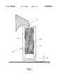
- FIG. 1shows a partly sectioned side view of a curtain coating installation of the invention
- FIG. 2shows a partly sectioned front view of the installation of FIG. 1;
- FIG. 3shows the flow of the liquid film along the porous plate shown in FIG. 1;
- FIG. 4shows a diagram of the thickness of the porous plate as a function of the distance along the curtain edge.
- Thin curtains and low falling velocitiesare mainly encountered in the vicinity of the lateral curtain guides since the curtain is locally constricted due to the process of wetting the lateral guide, on one hand, and because the falling velocity of the curtain is reduced by the lateral guide, on the other hand.
- V 0initial velocity of the curtain
- xfalling height of the curtain as measured from the origin of the curtain
- ⁇angle of inclination of the liquid film with respect to the vertical direction
- the lateral guideis terminated at its lower end by a cutting blade.
- This bladecuts off a border zone of the curtain which is extracted along with the liquid film and therefore causes losses of coating solution which may be very costly.
- Another particularly negative effectis that the cutting blade, whose length in the falling direction of the curtain is limited and amounts to several millimeters, represents a lateral border in the form of a stationary wall which decelerates the curtain at the very location where it is exposed to many disturbances from the moving support web. The cutting blade therefore causes a reduction of the curtain stability as well.
- the present inventioneliminates the above-mentioned disadvantages, i.e. it increases the curtain stability due to the fact that the liquid film on the planar lateral curtain guide is of such a nature that its surface velocity is identical to the falling velocity of the curtain at any point along the lateral guide and therefore causes no local distortions and constrictions of the curtain, and because there is no stationary wall in the form of a cutting blade in the lower section of the curtain which might decelerate the descent of the curtain.
- FIGS. 1 and 2show the pouring lip 1, a porous plate 2 which is disposed between two edge plates 3 and 4, thus forming a channel 15, as well as a suction slit 5 and the support web 6.
- the curtainis indicated by the two arrows 7, whereas a water film 8 is illustrated, in FIG. 3.
- water supply 9 and vacuum line 10which leads to suction slit 5.
- a part of rear wall 16 of the lateral guideis visible in which supply 9 is arranged.
- a liquid of low viscositypreferably water, runs down vertically.
- the temperature of this liquidmust be equal to the temperature of the coating solution in the curtain.
- the width of channel 15, which corresponds to the width of porous plate 2 (see FIG. 1),must be chosen such that the curtain, depending on its falling curve, may adhere to the liquid film without hindrance, and is preferably between 10 and 20 mm.
- the depth of the channelmust be somewhat greater than the thickness of the liquid film flowing in it, i.e. 0.2 to 0.4 mm, preferably 0.5 to 3.0 mm
- the surface of the channel facing the curtainis composed on its entire length of a porous material through which the liquid flows that forms the liquid film on the lateral edge.
- the obtained liquid filmis constantly supplied with liquid all along the flowing direction, so that the thickness of the liquid film continuously increases from the top to the bottom, see also FIG. 3.
- the porous materialis in the form of a plate 2 whose thickness H p varies over the length of the lateral guide.
- the liquidis supplied to the porous plate from supply 9 which is arranged behind porous plate 2 on the entire length of the lateral guide.
- This supplyis connected in turn to a non-represented liquid supply system, e.g. a tank with a pump.
- the thickness H p of the porous platehas to be designed such that at any point thereof, the precise amount of liquid may flow through the plate which allows a downward surface velocity of the liquid film created on the other side of the plate that corresponds exactly to the continuously increasing falling velocity of the curtain.
- the plate thicknesscan be calculated on the basis of the following considerations:
- volume flow/channel width of the liquid film between the entrance into and the exit from the reference volumeexactly corresponds to the volume flow/channel width which flows into the reference volume through the porous plate.
- volume flowis equal to the product of the flow rate through the porous plate and the height dx of the control volume, see FIG. 3. Accordingly,
- the thickness of the porous platedepends on the properties of the flowing liquid and of the porous material, as well as on the liquid pressure po behind the porous plate, which determines the minimum thickness of the plate.
- the dependence of the plate thickness from the distance along the plate and the liquid pressure p 0is shown in FIG. 4 by way of an example.
- the thickness of the porous platevaries e.g. between approx. 2 mm and approx. 8.7 mm over a length of the lateral border of 150 mm.
- the lower section 11 of the channelis not made of a porous material but of a solid material of good wetting properties.
- This lower section of the channelis composed of a lower portion 13 and an upper portion 14.
- the surface 17 on the curtain side of the upper portionis slightly inclined with respect to the vertical direction in order to increase the stability of the curtain.
- the angle of inclinationis preferably between 1° and 5°.
- the suction slit 5is provided which extends across the entire channel width transversely to the liquid flow.
- This suction slitwhose height is between 0.1 and 1.0 mm, preferably between 0.3 and 0.5 mm, extracts the liquid flowing through the porous plate, as well as possibly a small quantity of the curtain liquid.
- the separation of the liquid which is extracted from the curtain which is applied to the supportis effected at the lower edge 12 of the suction slit.
- the edgeis located at the end of the lower portion 13 of the suction slit, the lower surface 18 of said lower portion including an angle between 1° to 60°, preferably of 45° to 60° with respect to the horizontal direction.
- Edge 12 of the suction slitfurthermore projects by a distance between 0 and 5 mm, preferably between 1 and 3 mm, from the upper portion 14 of the suction slit. This projecting edge serves as an impact surface for the lateral liquid and allows for an easier extraction of the latter.
- this portionmust not extend in parallel to the support surface so as to form a narrow gap into which the liquid of the curtain or from the coated film might be aspired by capillary attraction, thus impairing the quality of the coated margin or even making it impossible to maintain a coherent coating process.
- the lower edge 12 of the suction slitis disposed at a distance of 0.1 to 1.0 mm, preferably 0.3 to 0.5 mm above the support web. This short distance prevents the curtain from forming a large edge bulb as it is detached from the edge.
Landscapes
- Chemical & Material Sciences (AREA)
- Engineering & Computer Science (AREA)
- Materials Engineering (AREA)
- Physics & Mathematics (AREA)
- General Physics & Mathematics (AREA)
- Application Of Or Painting With Fluid Materials (AREA)
- Coating Apparatus (AREA)
Abstract
Description
dQ.sub.f =dQ.sub.p =V.sub.p dx ##EQU3##
Claims (12)
Applications Claiming Priority (2)
| Application Number | Priority Date | Filing Date | Title |
|---|---|---|---|
| EP97810733AEP0907103B1 (en) | 1997-10-03 | 1997-10-03 | Process and apparatus for curtain coating a moving substrate |
| EP97810733 | 1997-10-03 |
Publications (1)
| Publication Number | Publication Date |
|---|---|
| US6048582Atrue US6048582A (en) | 2000-04-11 |
Family
ID=8230415
Family Applications (1)
| Application Number | Title | Priority Date | Filing Date |
|---|---|---|---|
| US09/165,989Expired - Fee RelatedUS6048582A (en) | 1997-10-03 | 1998-10-02 | Method and apparatus for curtain coating providing a lateral liquid film velocity equal to the curtain falling velocity |
Country Status (4)
| Country | Link |
|---|---|
| US (1) | US6048582A (en) |
| EP (1) | EP0907103B1 (en) |
| JP (1) | JPH11188299A (en) |
| DE (1) | DE59702151D1 (en) |
Cited By (6)
| Publication number | Priority date | Publication date | Assignee | Title |
|---|---|---|---|---|
| WO2002081103A1 (en)* | 2001-04-09 | 2002-10-17 | Bachofen + Meier Ag Maschinenfabrik | Device for coating a moving material web |
| US6528128B2 (en)* | 1999-04-21 | 2003-03-04 | Kabushiki Kaisha Toshiba | Method of treating a substrate |
| US20040047999A1 (en)* | 2002-09-10 | 2004-03-11 | Ilford Imaging, Switzerland Gmbh. | Method and device for coating a moving web |
| WO2005097352A1 (en)* | 2004-04-06 | 2005-10-20 | Polytype Converting S.A. | Curtain coating device and curtain coating method |
| US20110070377A1 (en)* | 2006-09-15 | 2011-03-24 | Ricoh Company, Ltd. | Slide curtain coating apparatus and slide curtain coating method |
| CN102497936A (en)* | 2009-08-31 | 2012-06-13 | 威斯专利股份有限公司 | Edge guide of curtain coater |
Families Citing this family (9)
| Publication number | Priority date | Publication date | Assignee | Title |
|---|---|---|---|---|
| EP1458492B1 (en) | 2001-12-13 | 2010-05-05 | Dow Global Technologies Inc. | Method and apparatus for curtain coating |
| JP5259135B2 (en)* | 2007-07-31 | 2013-08-07 | 日本製紙株式会社 | Curtain coating device |
| JP5228227B2 (en)* | 2007-12-05 | 2013-07-03 | ボイス パテント ゲーエムベーハー | Curtain coater edge guide |
| JP2009172471A (en)* | 2008-01-22 | 2009-08-06 | Voith Patent Gmbh | Edge guide of curtain coater |
| JP5439880B2 (en) | 2008-03-17 | 2014-03-12 | 株式会社リコー | Curtain coating apparatus and curtain coating method |
| US8522713B2 (en) | 2008-07-22 | 2013-09-03 | Ricoh Company, Ltd. | Curtain coating method and curtain coating apparatus |
| DE102008054892A1 (en)* | 2008-12-18 | 2010-06-24 | Voith Patent Gmbh | Curtain applicator |
| DE102012004875B3 (en)* | 2012-03-10 | 2012-07-19 | Andritz Küsters Gmbh | Device for curtain coating current material web e.g. paper web, has guide comprising suction apparatus with suction channel, and nozzle provided at channel, where steam at rear side of suction slot is injected into channel via nozzle |
| DE102014013996A1 (en) | 2014-09-25 | 2016-03-31 | Andritz Küsters Gmbh | Method and apparatus for curtain coating |
Citations (8)
| Publication number | Priority date | Publication date | Assignee | Title |
|---|---|---|---|---|
| US3632374A (en)* | 1968-06-03 | 1972-01-04 | Eastman Kodak Co | Method of making photographic elements |
| GB2021001A (en)* | 1977-11-09 | 1979-11-28 | Fuji Photo Film Co Ltd | Curtain Coating |
| US4479987A (en)* | 1983-01-04 | 1984-10-30 | Agfa-Gevaert Aktiengesellschaft | Process and an apparatus for stabilizing free-falling liquid curtains |
| US4974533A (en)* | 1988-02-01 | 1990-12-04 | Fuji Photo Film Co., Ltd. | Coating apparatus |
| EP0414721A1 (en)* | 1988-04-22 | 1991-03-06 | Eastman Kodak Co | Curtain coating method and apparatus. |
| US5395660A (en)* | 1993-01-07 | 1995-03-07 | Eastman Kodak Company | Edge removal apparatus for curtain coating |
| EP0737521A2 (en)* | 1995-04-10 | 1996-10-16 | Du Pont De Nemours (Deutschland) Gmbh | Method and device for reducing disturbances in curtain-coating |
| EP0740197A1 (en)* | 1995-04-26 | 1996-10-30 | Ilford Ag | Process and apparatus for curtain-coating a moving substrate |
- 1997
- 1997-10-03EPEP97810733Apatent/EP0907103B1/ennot_activeExpired - Lifetime
- 1997-10-03DEDE59702151Tpatent/DE59702151D1/ennot_activeExpired - Lifetime
- 1998
- 1998-10-02USUS09/165,989patent/US6048582A/ennot_activeExpired - Fee Related
- 1998-10-05JPJP10282505Apatent/JPH11188299A/enactivePending
Patent Citations (8)
| Publication number | Priority date | Publication date | Assignee | Title |
|---|---|---|---|---|
| US3632374A (en)* | 1968-06-03 | 1972-01-04 | Eastman Kodak Co | Method of making photographic elements |
| GB2021001A (en)* | 1977-11-09 | 1979-11-28 | Fuji Photo Film Co Ltd | Curtain Coating |
| US4479987A (en)* | 1983-01-04 | 1984-10-30 | Agfa-Gevaert Aktiengesellschaft | Process and an apparatus for stabilizing free-falling liquid curtains |
| US4974533A (en)* | 1988-02-01 | 1990-12-04 | Fuji Photo Film Co., Ltd. | Coating apparatus |
| EP0414721A1 (en)* | 1988-04-22 | 1991-03-06 | Eastman Kodak Co | Curtain coating method and apparatus. |
| US5395660A (en)* | 1993-01-07 | 1995-03-07 | Eastman Kodak Company | Edge removal apparatus for curtain coating |
| EP0737521A2 (en)* | 1995-04-10 | 1996-10-16 | Du Pont De Nemours (Deutschland) Gmbh | Method and device for reducing disturbances in curtain-coating |
| EP0740197A1 (en)* | 1995-04-26 | 1996-10-30 | Ilford Ag | Process and apparatus for curtain-coating a moving substrate |
Non-Patent Citations (2)
| Title |
|---|
| P. Grassman, Physikalische Grundlagen der Verfahrenstechnik , 1970, Sauerl a nder AG, Aarau, (No Month Date).* |
| P. Grassman, Physikalische Grundlagen der Verfahrenstechnik, 1970, Sauerlander AG, Aarau, (No Month Date). |
Cited By (11)
| Publication number | Priority date | Publication date | Assignee | Title |
|---|---|---|---|---|
| US6528128B2 (en)* | 1999-04-21 | 2003-03-04 | Kabushiki Kaisha Toshiba | Method of treating a substrate |
| WO2002081103A1 (en)* | 2001-04-09 | 2002-10-17 | Bachofen + Meier Ag Maschinenfabrik | Device for coating a moving material web |
| US20050126479A1 (en)* | 2001-04-09 | 2005-06-16 | Rolf Metzger | Device for coating a moving material web |
| US7081163B2 (en)* | 2001-04-09 | 2006-07-25 | Bachofen + Meier Ag Maschinenfabrik | Edge-control system for curtain coater |
| US20040047999A1 (en)* | 2002-09-10 | 2004-03-11 | Ilford Imaging, Switzerland Gmbh. | Method and device for coating a moving web |
| US7160579B2 (en) | 2002-09-10 | 2007-01-09 | Ilford Imaging Switzerland Gmbh | Method and device for coating a moving web |
| WO2005097352A1 (en)* | 2004-04-06 | 2005-10-20 | Polytype Converting S.A. | Curtain coating device and curtain coating method |
| US20070137563A1 (en)* | 2004-04-06 | 2007-06-21 | Peter Schweizer | Curtain coater and curtain coating method |
| US20110070377A1 (en)* | 2006-09-15 | 2011-03-24 | Ricoh Company, Ltd. | Slide curtain coating apparatus and slide curtain coating method |
| US8343588B2 (en)* | 2006-09-15 | 2013-01-01 | Ricoh Company, Ltd. | Slide curtain coating apparatus and slide curtain coating method |
| CN102497936A (en)* | 2009-08-31 | 2012-06-13 | 威斯专利股份有限公司 | Edge guide of curtain coater |
Also Published As
| Publication number | Publication date |
|---|---|
| EP0907103B1 (en) | 2000-08-09 |
| DE59702151D1 (en) | 2000-09-14 |
| EP0907103A1 (en) | 1999-04-07 |
| JPH11188299A (en) | 1999-07-13 |
Similar Documents
| Publication | Publication Date | Title |
|---|---|---|
| US6048582A (en) | Method and apparatus for curtain coating providing a lateral liquid film velocity equal to the curtain falling velocity | |
| EP0606038B1 (en) | Edge removal apparatus for curtain coating | |
| EP0636423B1 (en) | Edge guide lubricating fluid delivery apparatus | |
| KR0172451B1 (en) | Automatic swing adobe | |
| JPH08323263A (en) | Method and apparatus for reducing turbulence in curtain coating | |
| US5624715A (en) | Method and apparatus for curtain coating a moving support | |
| US4851268A (en) | Curtain coating start-up method and apparatus | |
| US5328726A (en) | Curtain coating method and apparatus using dual wire edge guides | |
| EP0943961A2 (en) | Curtain coating apparatus and method with continuous width adjustment | |
| US4283443A (en) | Method and apparatus for coating webs | |
| EP0537086B1 (en) | Curtain coating method and apparatus | |
| US3348964A (en) | Immersion coating of strip material | |
| EP0563308B1 (en) | Improvements in or relating to coating | |
| EP0649054B1 (en) | Stripe internal edging method and apparatus | |
| GB1559701A (en) | Curtain coating | |
| EP0931596B1 (en) | Curtain coating method and apparatus | |
| US4427722A (en) | Apparatus for applying a controlled layer of a saturant or a coating via a free-falling vertical curtain | |
| US6162502A (en) | Method and device for curtain coating a moving support | |
| US20050126479A1 (en) | Device for coating a moving material web | |
| GB2117006A (en) | Pickling line for continuous metal strip | |
| FI66042B (en) | ANORDNING FOER BESTRYKNING AV BANA | |
| SE459323B (en) | DEVICE FOR COATING A MAIN VERTICALLY CREATED MOVE ROAD, WIRELESS WAY AND A PAPER COAT | |
| RU2100137C1 (en) | Gear to feed melt in plant for continuous casting of aluminium | |
| US5683510A (en) | Coater with air collector | |
| JP2749172B2 (en) | Paint supply equipment for curtain coating |
Legal Events
| Date | Code | Title | Description |
|---|---|---|---|
| AS | Assignment | Owner name:TROLLER SCHWEIZER ENGINEERING AG, SWITZERLAND Free format text:ASSIGNMENT OF ASSIGNORS INTEREST;ASSIGNORS:SCHWEIZER, PETER M.;TROLLER, URS;REEL/FRAME:009812/0014 Effective date:19981001 | |
| AS | Assignment | Owner name:TSE TROLLER SCHWEIZER ENGINEERING AG, SWITZERLAND Free format text:ASSIGNMENT OF ASSIGNORS INTEREST;ASSIGNOR:TROLLER SCHWEIZER ENGINEERING AG;REEL/FRAME:011410/0749 Effective date:20001204 | |
| FPAY | Fee payment | Year of fee payment:4 | |
| FEPP | Fee payment procedure | Free format text:PAYOR NUMBER ASSIGNED (ORIGINAL EVENT CODE: ASPN); ENTITY STATUS OF PATENT OWNER: SMALL ENTITY | |
| FPAY | Fee payment | Year of fee payment:8 | |
| AS | Assignment | Owner name:VESTINCOAT AG, SWITZERLAND Free format text:CHANGE OF NAME;ASSIGNOR:TSE TROLLER SCHWEIZER ENGINEERING AG;REEL/FRAME:021531/0111 Effective date:20080103 | |
| REMI | Maintenance fee reminder mailed | ||
| LAPS | Lapse for failure to pay maintenance fees | ||
| STCH | Information on status: patent discontinuation | Free format text:PATENT EXPIRED DUE TO NONPAYMENT OF MAINTENANCE FEES UNDER 37 CFR 1.362 | |
| FP | Lapsed due to failure to pay maintenance fee | Effective date:20120411 |