US6048455A - Filter assembly with conformal cartridge support structure - Google Patents
Filter assembly with conformal cartridge support structureDownload PDFInfo
- Publication number
- US6048455A US6048455AUS08/918,608US91860897AUS6048455AUS 6048455 AUS6048455 AUS 6048455AUS 91860897 AUS91860897 AUS 91860897AUS 6048455 AUS6048455 AUS 6048455A
- Authority
- US
- United States
- Prior art keywords
- base
- cartridge
- filter assembly
- engagement surface
- filter
- Prior art date
- Legal status (The legal status is an assumption and is not a legal conclusion. Google has not performed a legal analysis and makes no representation as to the accuracy of the status listed.)
- Expired - Lifetime
Links
Images


Classifications
- B—PERFORMING OPERATIONS; TRANSPORTING
- B01—PHYSICAL OR CHEMICAL PROCESSES OR APPARATUS IN GENERAL
- B01D—SEPARATION
- B01D35/00—Filtering devices having features not specifically covered by groups B01D24/00 - B01D33/00, or for applications not specifically covered by groups B01D24/00 - B01D33/00; Auxiliary devices for filtration; Filter housing constructions
- B01D35/30—Filter housing constructions
- B—PERFORMING OPERATIONS; TRANSPORTING
- B01—PHYSICAL OR CHEMICAL PROCESSES OR APPARATUS IN GENERAL
- B01D—SEPARATION
- B01D27/00—Cartridge filters of the throw-away type
- B01D27/04—Cartridge filters of the throw-away type with cartridges made of a piece of unitary material, e.g. filter paper
- B01D27/06—Cartridge filters of the throw-away type with cartridges made of a piece of unitary material, e.g. filter paper with corrugated, folded or wound material
- B—PERFORMING OPERATIONS; TRANSPORTING
- B01—PHYSICAL OR CHEMICAL PROCESSES OR APPARATUS IN GENERAL
- B01D—SEPARATION
- B01D27/00—Cartridge filters of the throw-away type
- B01D27/08—Construction of the casing
- B—PERFORMING OPERATIONS; TRANSPORTING
- B01—PHYSICAL OR CHEMICAL PROCESSES OR APPARATUS IN GENERAL
- B01D—SEPARATION
- B01D2201/00—Details relating to filtering apparatus
- B01D2201/34—Seals or gaskets for filtering elements
- B—PERFORMING OPERATIONS; TRANSPORTING
- B01—PHYSICAL OR CHEMICAL PROCESSES OR APPARATUS IN GENERAL
- B01D—SEPARATION
- B01D2201/00—Details relating to filtering apparatus
- B01D2201/40—Special measures for connecting different parts of the filter
- B01D2201/4046—Means for avoiding false mounting of different parts
Definitions
- This inventionrelates generally to fuel filters employed in connection with internal combustion engines. More particularly, the present invention relates to fuel filters and lubricating oil filters having a replaceable cartridge for removing foreign particles and/or separating water from the fuel supply or oil system of an internal combustion engine.
- filtersemploy a disposable filter cartridge which is replaced at pre-established intervals of filter usage.
- the cartridgeis secured to a base assembly that is mounted to the engine header or some other fixed location.
- Fuel systemsutilize various pump arrangements to transport the fuel through the system, thereby internally pressurizing portions of the fuel system.
- Conventional fuel systemsgenerally expose the fuel filter cartridge to an internal pressure of up to 30 psi. Light gauge steel may therefore be used in the manufacture of filter cartridge housings for such conventional systems.
- fuel systems currently under developmentwill expose the fuel filter cartridge to internal pressures of greater than 50 psi. Such pressures may result in deformation of conventional cartridge housings resulting in rupture of the housing or failure of the cartridge-to-base seal.
- the inventionin a preferred form is a fuel filter assembly which comprises a base and a disposable filter cartridge.
- the filter cartridgeincludes a cartridge container having an upper section that is received in the base.
- the upper sectionis composed of material having a thickness and mechanical properties and a quasi-conformal configuration such that the force exerted on the interior surface of the cartridge container by operating pressure, such as, for example, greater than 50 psi, may plastically deform the exterior surface of the upper section into a more conformal engagement with the interior receiving surface of the base.
- a plurality of longitudinally extending keys or protrusionsprotrude from the bottom surface of the base.
- the protrusionsare selectively dimensioned and positioned to provide a unique protrusion matrix for a given filter capacity, filtering quality or filtering parameter.
- the top portion of the upper sectionis forced into a closer conformation with the lower receiving surface of the base which also functions to provide a support. Consequently, the protrusions form corresponding complementary depressions in the top portion of the upper section.
- Such engagementlocks the top portion of the upper section to the base, preventing rotation therebetween when the fuel system is operating.
- the configuration of the baseis selected such that the base supports the upper section of the container, preventing further deformation of the upper section. Consequently, the filter cartridge container does not require stand-alone pressure vessel design considerations to withstand the forces exerted by the relatively high fuel pressure.
- the height of the protrusions and the clearance between the receiving surface of the base and the opposing portion of the cartridge sectionare selected to ensure that the formed depressions and the protrusions have sufficient engagement to lock the cartridge in the base.
- the protrusionsare spaced such that the complementary depressions are distinct and do not overlap. Such configuration provides a superior locking mechanism, preventing slippage between the cartridge and the base.
- An object of the inventionis to provide a new and improved fuel filter system which employs a filter cartridge having an efficient and low cost construction and is capable of operating at high internal operating pressures.
- Another object of the inventionis to provide a new and improved location and key system for a fuel filter system that utilizes the fuel pressure or pressure cycles to form in a post-installation process a more conformal complementary structure that receives the key.
- a further object of the inventionis to provide a new and improved location and key system for locking the cartridge to the base and thereby preventing rotation therebetween.
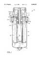
- FIG. 1is a sectional elevational view, partly broken away, of a fuel filter assembly in accordance with the invention
- FIG. 2is an enlarged fragmentary sectional view, partly in schematic, of the fuel filter assembly of FIG. 1;
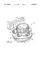
- FIG. 3is an enlarged perspective view of the base portion of the fuel filter assembly of FIG. 1;
- FIG. 4is an enlarged sectional view of the base portion of the fuel filter assembly of FIG. 1;
- FIG. 5is an enlarged bottom plan view of the base portion of the fuel filter assembly of FIG. 1;
- FIGS. 6a, 6b and 6care enlarged bottom plan views of the base portion of the fuel filter assembly of FIG. 1 showing an alternate embodiment of a locking protrusion
- FIG. 7is an enlarged fragmentary sectional view of the filter cartridge of FIG. 1 in a pre-installation configuration.
- Fuel filter assembly 10comprises a base 12 and a disposable filter cartridge 14.
- the base 12is disposed generally above the disposable filter cartridge 14 which is locked to the base 12 by means of a retainer collar 16.
- the base and filter cartridgemay be inverted wherein the filter cartridge is disposed above the base.
- the fuel filter assembly 10is especially adapted for incorporation into the fuel supply system of an internal combustion engine (not illustrated), such as a diesel engine, for removing particulate matter from fuel and separating the water from the fuel. Filters of this type may also be used to filter impurities from oil in the lubricating system of an internal combustion engine or for other filter applications.
- the base 12 and the disposable cartridge 14may assume a wide variety of configurations.
- the base 12is an inverted cup-like receptacle which forms a skirt 18 defining a lower receptacle cavity 20 for upper portions 22 of the disposable cartridge 14.
- An elongated sleeve-like first conduit 24 and an outer concentric sleeve-like second conduit 26provide generally co-axial fluid communication between the base 12 and the disposable cartridge 14.
- an inlet connector 28 at an upper side location of the base 12connects with the fuel line (not illustrated) to ultimately provide fluid communication through the interior passageway defined by the first conduit 24.
- An outlet connector 30 at an upper side location of the base 12connects with the fuel line to provide external fluid communication from the axial fluid conduit defined between the first and second conduits 24, 26.
- An integral projecting bracket 32which may include a pair of openings 34 for anchoring the filter base 12 to the engine extends transversely from the base 12.
- the base 12may also have an external air vent 36.
- the base 12may include a pair of integral outwardly projecting diametrically opposed ramps 38 which ascend in spiral-like fashion around the base 12.
- the upper ends of the ramps 38are beveled.
- the collar 16includes a pair of diametrically disposed spiral followers (not shown) which integrally extend inwardly from the collar 16.
- the followersare dimensioned and positioned for engagement with the ramps 38 so that the followers slidably engage and ascend the ramps 38 upon alignment and angular rotation of the collar 16.
- the collar 16includes an inwardly projecting annular shoulder 40 which engages the roll seam 42 of the cartridge 14 for releasably locking the cartridge 14 to the base 12.
- a locking forceis releasably maintained by the force of a spring 44 which is retained in an annular recess 46 in the base 12.
- the recess 46is positioned adjacent the skirt 18 of the base 12.
- Some conventional filter assembliesinclude a spring for providing a locking force.
- springsare positioned closer to the axis of the filter base/cartridge than the spring 44 of the subject invention. Springs 44 located closer to the periphery of the filter base/cartridge may provide greater stability than do springs located closer to the axis. In addition such location allows room for key/locating protrusions 48 that protrude downwardly from the lower surface 50 of the base 12.
- a preferred embodimentis a wave spring having an upper surface 52 that abuts the surface of the recess 46 and a lower surface 54 that engages an annular ridge 56 on the top portion 58 of the upper section 62 of the filter cartridge enclosure 60.
- the spring 44functions to substantially uniformly distribute the load between the base 12 and the filter cartridge 14.
- a key systemis employed to lock the cartridge 14 to the base 12 and thereby prevent rotation therebetween.
- a plurality of longitudinally extending keys or protrusions 48protrude from the bottom surface 50 of the base 12 intermediate the recess 46 and the second conduit 26.
- the protrusions 48are disposed substantially equidistantly between the second conduit 26 and the recess 46.
- the protrusionsmay have the shape of a spherical sector cap 64, a pie wedge-shape 66, a square-shape 68, a bead or bump 70, or other non-spherical shape, as shown in FIGS. 4, 5 and 6a-6c.
- the protrusions 48may be spaced substantially 120° apart, as shown in FIG. 5.
- the disposable filter cartridge 14comprises a can-like enclosure 60 formed by a pair of opposed lower and upper cup-like sections 72, 62.
- the sections 62, 72are joined along a circumferential roll seam 42.
- a sump 74is formed at the bottom of the lower section 72 to collect water which coalesces from the fuel.
- the upper section 62which is smaller in diameter than the lower section 72, is received by the base receptacle 20.
- the upper section 62is dimensioned to be closely accommodated in the base receptacle 20.
- the top portion 58 of the cartridgemay deform from the pre-installation configuration of FIG. 7 to the installed configuration of FIGS.
- the pre-installation configurationmay have a quasi-conformal shape in relation to the adjacent receiving/ structure of the base.
- a central axial opening 76 in the upper section 62is dimensioned to receive the conduits 24, 26.
- a sealing grommet 78 mounted at the opening 76diametrally fluidically seals against the outer conduit 26.
- the cartridge 14may employ a dual stage filter assembly or a single stage assembly as illustrated in FIGS. 1 and 2.
- a filter element 80which has a continuous fan-shaped pleated configuration is mounted in the enclosure 60. The lower end of the element 80 is engaged by a medial plate 82 having a central opening 84.
- a tubular conduit 86extends upward from the medial plate 82. The tubular conduit 86 upper end defines a flange 88.
- a second sealing grommet 90 mounted to the flange 88receives and diametrally seals against the lower end of the base first conduit 24.
- the upper section 62 of the filter cartridge enclosure 60is preferably composed of drawn quality steel having a thickness of 0.018 to 0.024 inches.
- the force exerted on the interior surface 92 (FIGS. 2 and 7) of the enclosure 60may plastically deform the upper section 62 of the enclosure 60, forcing the exterior surface 94 of the upper section 62 into a closer conformal engagement with the interior receiving surface 96 of the base 12.
- the configuration of the base 12is selected such that the base 12 reinforces the upper section 62 of the enclosure 60, preventing further deformation of the upper section 62 and providing an efficient pressure vessel-type wall structure.
- the base 12is preferably die cast aluminum A380 material to provide sufficient mechanical strength to support the cartridge 14 and withstand the internal operating pressures within the cartridge. It should be appreciated that the upper section 62 of the enclosure 60 functions primarily as a membrane to contain the fluid, since the base 12 provides the mechanical support to withstand the pressure force.
- the top portion 58 of the upper section 62may be pre-formed in a quasi-conformal configuration with the base and is forced into closer conformation with the lower surface 50 of the base 12 when the filter cartridge 14 is at operating pressure or as a result of the numerous pressure changes during the operational life of the cartridge.
- the pre-installation quasi-conformal configurationincludes depressions which correspond in angular and radial positioning to the protrusions 48. Consequently, the three protrusions 48 which project from the lower surface 50 of the base 12 form corresponding depressions or dimples 98 in the upper surface 61 of the top portion 58 of the upper section 62.
- these depressions or dimplesare more closely conformed to the protrusions during the operation of the filter because of the pressure induced forces produced within the cartridge.
- Such conformal engagementlocks the top portion 58 of the upper section 62 to the base 12, preventing rotation of therebetween when the fuel system is operating. It should be appreciated that the spring 44 performs no function when the fuel system is at operating pressure.
- the protrusions 48project at least 0.150 inches from the lower surface 50 of the base 12 and the clearance between the lower surface 50 of the base 12 and the top portion 58 of the upper section 62 when the filter assembly is not pressurized is 0.010 to 0.020 inches to ensure that the dimple 98 and the protrusion 48 have sufficient engagement to lock the cartridge 14 in the base 12.
- each protrusion 64has a diameter in the range of 0.150 to 0.750 inches to ensure sufficient engagement between the filter cartridge and the base.
- Such protrusions 64may be axially spaced apart a sufficient distance to provide the proper separation between the dimples 98 formed in the top portion 58 of the upper section 62. It should be appreciated that the diameter of the protrusions 64 are in part determined by the diameter of the cartridge 14.
- each protrusion 64may have to be radially spaced from the axis of the adjacent protrusions 64 to provide proper separation between the dimples 98 formed in the top portion 58 of the upper section 62.
- the fuelenters the fuel filter assembly 10 through the fuel inlet passage 28 and exits the filter through the outlet passage 30.
- the fuel flow pathinitially axially traverses through the interior of the inner conduit 24.
- the circulation pathextends generally axially upwardly and generally radially through the filter element 80 with the return flow path traversing between the inner conduit 24 and the outer conduit 26.
- the lower surface of the basemay include one or more recesses which receive a deformable protrusion formed in the top portion of the filter cartridge by the operating pressure of the fuel.
Landscapes
- Chemical & Material Sciences (AREA)
- Chemical Kinetics & Catalysis (AREA)
- Filtration Of Liquid (AREA)
- Lubrication Details And Ventilation Of Internal Combustion Engines (AREA)
- Pressure Vessels And Lids Thereof (AREA)
Abstract
Description
Claims (17)
Priority Applications (1)
| Application Number | Priority Date | Filing Date | Title |
|---|---|---|---|
| US08/918,608US6048455A (en) | 1996-08-22 | 1997-08-22 | Filter assembly with conformal cartridge support structure |
Applications Claiming Priority (2)
| Application Number | Priority Date | Filing Date | Title |
|---|---|---|---|
| US2343196P | 1996-08-22 | 1996-08-22 | |
| US08/918,608US6048455A (en) | 1996-08-22 | 1997-08-22 | Filter assembly with conformal cartridge support structure |
Publications (1)
| Publication Number | Publication Date |
|---|---|
| US6048455Atrue US6048455A (en) | 2000-04-11 |
Family
ID=21815056
Family Applications (1)
| Application Number | Title | Priority Date | Filing Date |
|---|---|---|---|
| US08/918,608Expired - LifetimeUS6048455A (en) | 1996-08-22 | 1997-08-22 | Filter assembly with conformal cartridge support structure |
Country Status (5)
| Country | Link |
|---|---|
| US (1) | US6048455A (en) |
| EP (1) | EP0826407B1 (en) |
| JP (1) | JPH10110657A (en) |
| DE (1) | DE69704315T2 (en) |
| ES (1) | ES2157505T3 (en) |
Cited By (74)
| Publication number | Priority date | Publication date | Assignee | Title |
|---|---|---|---|---|
| USD455194S1 (en) | 2001-03-26 | 2002-04-02 | Usf Consumer & Commercial Group, Inc. | Filter housing header |
| USD456486S1 (en) | 2001-03-26 | 2002-04-30 | Usf Consumer & Commercial Group, Inc. | Filter housing header |
| US20030217958A1 (en)* | 2002-02-21 | 2003-11-27 | Reid Roger P. | Quick change filter and bracket system with key system and universal key option |
| US6695891B2 (en)* | 2000-08-11 | 2004-02-24 | Roger P. Reid | Keyed system for connection of filter cartridge to filter holder |
| US6726030B1 (en) | 2002-04-03 | 2004-04-27 | Dana Corporation | Standpipe element support for liquid filter |
| US20040084360A1 (en)* | 2002-10-31 | 2004-05-06 | Stanadyne Corporation | Base receptacle for filter cartridge incorporating a peripheral compatibility matrix |
| US20040206679A1 (en)* | 2002-11-25 | 2004-10-21 | Bleigh James M | Strainer assembly |
| US20040232064A1 (en)* | 2003-05-23 | 2004-11-25 | James Wilkinson | Cartridge filters and housing connections therefor |
| US20040238431A1 (en)* | 1999-04-20 | 2004-12-02 | Johnson Warren Thomas | Membrane filtration manifold system |
| US20060162305A1 (en)* | 2000-08-11 | 2006-07-27 | Reid Roger P | Keyed system for connection of filter cartridge to filter holder |
| US20060186031A1 (en)* | 2005-02-22 | 2006-08-24 | Baldwin Filters, Inc. | Filter apparatus |
| US20070138090A1 (en)* | 2005-10-05 | 2007-06-21 | Jordan Edward J | Method and apparatus for treating wastewater |
| US20070267340A1 (en)* | 2006-05-22 | 2007-11-22 | Bleigh James M | Hydrofoil-shaped suction strainer with an internal core tube |
| US20080093297A1 (en)* | 2005-01-14 | 2008-04-24 | Gock Kenneth W | Filtration System |
| CN100387321C (en)* | 2002-10-31 | 2008-05-14 | 斯塔纳迪恩公司 | Eccentric interference retention system for filter cartridge |
| US7387723B2 (en) | 2004-04-22 | 2008-06-17 | Siemens Water Technologies Corp. | Filtration apparatus comprising a membrane bioreactor and a treatment vessel for digesting organic materials |
| US20080245719A1 (en)* | 2005-02-22 | 2008-10-09 | Baldwin Filters, Inc. | Filter Element And Filter Assembly Including Locking Mechanism |
| US7455765B2 (en) | 2006-01-25 | 2008-11-25 | Siemens Water Technologies Corp. | Wastewater treatment system and method |
| US20090078626A1 (en)* | 2007-09-21 | 2009-03-26 | Baldwin Filters, Inc. | Filter Cartridge Housing Attachment Systems |
| US7563363B2 (en) | 2005-10-05 | 2009-07-21 | Siemens Water Technologies Corp. | System for treating wastewater |
| US7591950B2 (en) | 2004-11-02 | 2009-09-22 | Siemens Water Technologies Corp. | Submerged cross-flow filtration |
| US7632439B2 (en) | 2002-02-12 | 2009-12-15 | Siemens Water Technologies Corp. | Poly(ethylene chlorotrifluoroethylene) membranes |
| US20090308801A1 (en)* | 2008-06-16 | 2009-12-17 | Baldwin Filters, Inc. | Fluid Filter, Fluid Filter Assembly, And Mounting Method |
| US20090308802A1 (en)* | 2008-06-16 | 2009-12-17 | Baldwin Filters, Inc. | Filter With Ejection Mechanism |
| US20090308803A1 (en)* | 2008-06-16 | 2009-12-17 | Baldwin Filters, Inc. | Filter With Water Separation Device |
| US20100155321A1 (en)* | 2008-12-23 | 2010-06-24 | Sasur Timothy M | Filter assembly |
| US7862719B2 (en) | 2004-08-20 | 2011-01-04 | Siemens Water Technologies Corp. | Square membrane manifold system |
| US7931463B2 (en) | 2001-04-04 | 2011-04-26 | Siemens Water Technologies Corp. | Apparatus for potting membranes |
| US7938966B2 (en) | 2002-10-10 | 2011-05-10 | Siemens Water Technologies Corp. | Backwash method |
| US20110203985A1 (en)* | 2009-08-21 | 2011-08-25 | Omnipure Filter Company, Pllc | Keyed system for connection of filter to filter holder |
| US8048306B2 (en) | 1996-12-20 | 2011-11-01 | Siemens Industry, Inc. | Scouring method |
| US8182687B2 (en) | 2002-06-18 | 2012-05-22 | Siemens Industry, Inc. | Methods of minimising the effect of integrity loss in hollow fibre membrane modules |
| US8268176B2 (en) | 2003-08-29 | 2012-09-18 | Siemens Industry, Inc. | Backwash |
| US8287743B2 (en) | 2007-05-29 | 2012-10-16 | Siemens Industry, Inc. | Membrane cleaning with pulsed airlift pump |
| US8293098B2 (en) | 2006-10-24 | 2012-10-23 | Siemens Industry, Inc. | Infiltration/inflow control for membrane bioreactor |
| US8318028B2 (en) | 2007-04-02 | 2012-11-27 | Siemens Industry, Inc. | Infiltration/inflow control for membrane bioreactor |
| US8372282B2 (en) | 2002-12-05 | 2013-02-12 | Siemens Industry, Inc. | Mixing chamber |
| US8377305B2 (en) | 2004-09-15 | 2013-02-19 | Siemens Industry, Inc. | Continuously variable aeration |
| US8382981B2 (en) | 2008-07-24 | 2013-02-26 | Siemens Industry, Inc. | Frame system for membrane filtration modules |
| USD679779S1 (en) | 2010-03-03 | 2013-04-09 | Omnipure Filter Company, Inc. | Filter for liquid |
| US8496828B2 (en) | 2004-12-24 | 2013-07-30 | Siemens Industry, Inc. | Cleaning in membrane filtration systems |
| US8506806B2 (en) | 2004-09-14 | 2013-08-13 | Siemens Industry, Inc. | Methods and apparatus for removing solids from a membrane module |
| US8512568B2 (en) | 2001-08-09 | 2013-08-20 | Siemens Industry, Inc. | Method of cleaning membrane modules |
| US8652331B2 (en) | 2008-08-20 | 2014-02-18 | Siemens Water Technologies Llc | Membrane system backwash energy efficiency |
| US8758622B2 (en) | 2004-12-24 | 2014-06-24 | Evoqua Water Technologies Llc | Simple gas scouring method and apparatus |
| US8758621B2 (en) | 2004-03-26 | 2014-06-24 | Evoqua Water Technologies Llc | Process and apparatus for purifying impure water using microfiltration or ultrafiltration in combination with reverse osmosis |
| US8790515B2 (en) | 2004-09-07 | 2014-07-29 | Evoqua Water Technologies Llc | Reduction of backwash liquid waste |
| US8808540B2 (en) | 2003-11-14 | 2014-08-19 | Evoqua Water Technologies Llc | Module cleaning method |
| USD712007S1 (en) | 2010-03-03 | 2014-08-26 | Omnipure Filter Company, Inc. | Filter for liquid |
| US8858796B2 (en) | 2005-08-22 | 2014-10-14 | Evoqua Water Technologies Llc | Assembly for water filtration using a tube manifold to minimise backwash |
| US8956464B2 (en) | 2009-06-11 | 2015-02-17 | Evoqua Water Technologies Llc | Method of cleaning membranes |
| US8991619B2 (en) | 2012-03-26 | 2015-03-31 | Baldwin Filters, Inc. | Filter assembly with water evacuation and methods |
| WO2015050580A1 (en)* | 2013-10-02 | 2015-04-09 | Clarcor Engine Mobile Solutions, Llc | Fuel filter cartridge and method of construction thereof |
| US9022224B2 (en) | 2010-09-24 | 2015-05-05 | Evoqua Water Technologies Llc | Fluid control manifold for membrane filtration system |
| US9314722B2 (en) | 2000-08-11 | 2016-04-19 | Omnipure Filter Company, Inc. | Keyed system for connection of filter cartridge to filter holder |
| US9533261B2 (en) | 2012-06-28 | 2017-01-03 | Evoqua Water Technologies Llc | Potting method |
| US9604166B2 (en) | 2011-09-30 | 2017-03-28 | Evoqua Water Technologies Llc | Manifold arrangement |
| USD786399S1 (en)* | 2015-08-13 | 2017-05-09 | Fuhr Gmbh | Filter housing |
| USD788263S1 (en)* | 2015-08-13 | 2017-05-30 | Fuhr Gmbh | Filter housing |
| US9675938B2 (en) | 2005-04-29 | 2017-06-13 | Evoqua Water Technologies Llc | Chemical clean for membrane filter |
| US9764288B2 (en) | 2007-04-04 | 2017-09-19 | Evoqua Water Technologies Llc | Membrane module protection |
| US9764289B2 (en) | 2012-09-26 | 2017-09-19 | Evoqua Water Technologies Llc | Membrane securement device |
| US9808744B2 (en) | 2013-01-04 | 2017-11-07 | Baldwin Filters, Inc. | Three-part end cap and filter element including same |
| US9815027B2 (en) | 2012-09-27 | 2017-11-14 | Evoqua Water Technologies Llc | Gas scouring apparatus for immersed membranes |
| US9914097B2 (en) | 2010-04-30 | 2018-03-13 | Evoqua Water Technologies Llc | Fluid flow distribution device |
| US9925499B2 (en) | 2011-09-30 | 2018-03-27 | Evoqua Water Technologies Llc | Isolation valve with seal for end cap of a filtration system |
| US9962865B2 (en) | 2012-09-26 | 2018-05-08 | Evoqua Water Technologies Llc | Membrane potting methods |
| US10322375B2 (en) | 2015-07-14 | 2019-06-18 | Evoqua Water Technologies Llc | Aeration device for filtration system |
| USD852319S1 (en)* | 2015-11-13 | 2019-06-25 | Briggs & Stratton Corporation | Oil filter |
| USD854650S1 (en) | 2017-09-15 | 2019-07-23 | Briggs & Stratton Corporation | Oil filter |
| US10427102B2 (en) | 2013-10-02 | 2019-10-01 | Evoqua Water Technologies Llc | Method and device for repairing a membrane filtration module |
| US11305213B2 (en) | 2017-05-31 | 2022-04-19 | Parker-Hannifin Corporation | Filter element with torsion lock and/or sliding piston, assembly and methods |
| US20230166203A1 (en)* | 2020-04-28 | 2023-06-01 | Amogreentech Co., Ltd. | Filter module for gravity-type water-purifying device and comprising the same |
| US11731065B2 (en) | 2016-10-03 | 2023-08-22 | Parker-Hannifin Corporation | Filter element with torsion lock and assembly |
Families Citing this family (6)
| Publication number | Priority date | Publication date | Assignee | Title |
|---|---|---|---|---|
| IT1311043B1 (en)* | 1999-11-03 | 2002-02-28 | Ufi Universal Filter Int Spa | GROUP FOR THE AUTOMATIC PURIFICATION OF SEPARATE WATER IN A VEHICLE FUEL FILTER, IN PARTICULAR FOR DIESEL ENGINES. |
| DE102005007021A1 (en)* | 2005-02-15 | 2006-08-24 | Mann + Hummel Gmbh | filter system |
| US7918997B2 (en) | 2005-02-15 | 2011-04-05 | Mann+Hummel Gmbh | Filter system |
| JP2011224481A (en)* | 2010-04-21 | 2011-11-10 | Roki Techno Co Ltd | Filter module and detaching apparatus of the same |
| GB2563840B (en)* | 2017-06-26 | 2020-09-09 | Ford Global Tech Llc | Oil filter fitting assembly |
| CN108619910B (en)* | 2018-05-23 | 2019-03-15 | 海鑫光电系统科技(上海)有限公司 | A kind of multifunctional efficient film filter |
Citations (8)
| Publication number | Priority date | Publication date | Assignee | Title |
|---|---|---|---|---|
| US2888141A (en)* | 1956-11-27 | 1959-05-26 | Fram Corp | Oil filters |
| US3727764A (en)* | 1971-11-22 | 1973-04-17 | H Ogden | Filtering apparatus having an integrally removable filter cartridge |
| EP0270303A2 (en)* | 1986-12-03 | 1988-06-08 | Pall Corporation | Filter assemblies |
| US4818396A (en)* | 1988-05-11 | 1989-04-04 | Joachim Wolf | Device for a filter |
| US4857195A (en)* | 1988-07-15 | 1989-08-15 | Allied-Signal Inc. | Liquid filter with a distorting portion for transmitting hydraulic forces |
| EP0442365A2 (en)* | 1990-02-14 | 1991-08-21 | Stanadyne Automotive Corp. | Key system for filter assembly |
| WO1995011072A1 (en)* | 1993-10-21 | 1995-04-27 | Tawas Industries | Oil and fuel filter canister and housing |
| US5837137A (en)* | 1996-08-21 | 1998-11-17 | Stanadyne Automotive Corp. | Base/cartridge location and key system for fuel filter assembly |
- 1997
- 1997-08-21JPJP9262632Apatent/JPH10110657A/enactivePending
- 1997-08-22USUS08/918,608patent/US6048455A/ennot_activeExpired - Lifetime
- 1997-08-22DEDE69704315Tpatent/DE69704315T2/ennot_activeExpired - Fee Related
- 1997-08-22EPEP97114585Apatent/EP0826407B1/ennot_activeExpired - Lifetime
- 1997-08-22ESES97114585Tpatent/ES2157505T3/ennot_activeExpired - Lifetime
Patent Citations (8)
| Publication number | Priority date | Publication date | Assignee | Title |
|---|---|---|---|---|
| US2888141A (en)* | 1956-11-27 | 1959-05-26 | Fram Corp | Oil filters |
| US3727764A (en)* | 1971-11-22 | 1973-04-17 | H Ogden | Filtering apparatus having an integrally removable filter cartridge |
| EP0270303A2 (en)* | 1986-12-03 | 1988-06-08 | Pall Corporation | Filter assemblies |
| US4818396A (en)* | 1988-05-11 | 1989-04-04 | Joachim Wolf | Device for a filter |
| US4857195A (en)* | 1988-07-15 | 1989-08-15 | Allied-Signal Inc. | Liquid filter with a distorting portion for transmitting hydraulic forces |
| EP0442365A2 (en)* | 1990-02-14 | 1991-08-21 | Stanadyne Automotive Corp. | Key system for filter assembly |
| WO1995011072A1 (en)* | 1993-10-21 | 1995-04-27 | Tawas Industries | Oil and fuel filter canister and housing |
| US5837137A (en)* | 1996-08-21 | 1998-11-17 | Stanadyne Automotive Corp. | Base/cartridge location and key system for fuel filter assembly |
Cited By (126)
| Publication number | Priority date | Publication date | Assignee | Title |
|---|---|---|---|---|
| US8048306B2 (en) | 1996-12-20 | 2011-11-01 | Siemens Industry, Inc. | Scouring method |
| US20040238431A1 (en)* | 1999-04-20 | 2004-12-02 | Johnson Warren Thomas | Membrane filtration manifold system |
| US7264716B2 (en)* | 1999-04-20 | 2007-09-04 | Siemens Water Technologies Corp. | Membrane filtration manifold system |
| US10737206B2 (en) | 2000-08-11 | 2020-08-11 | Omnipure Filter Company, Inc. | Keyed system for connection of filter cartridge to filter holder |
| US9314722B2 (en) | 2000-08-11 | 2016-04-19 | Omnipure Filter Company, Inc. | Keyed system for connection of filter cartridge to filter holder |
| US20060162305A1 (en)* | 2000-08-11 | 2006-07-27 | Reid Roger P | Keyed system for connection of filter cartridge to filter holder |
| US9421485B2 (en) | 2000-08-11 | 2016-08-23 | Omnipure Filter Company, Inc | Keyed system for connection of filter cartridge to filter holder |
| US20040163371A1 (en)* | 2000-08-11 | 2004-08-26 | Reid Roger P. | Keyed system for connection of filter cartridge to filter holder |
| US6977006B2 (en) | 2000-08-11 | 2005-12-20 | Reid Roger P | Keyed system for connection of filter cartridge to filter holder |
| US6695891B2 (en)* | 2000-08-11 | 2004-02-24 | Roger P. Reid | Keyed system for connection of filter cartridge to filter holder |
| US7476314B2 (en) | 2000-08-11 | 2009-01-13 | Reid Roger P | Keyed system for connection of filter cartridge to filter holder |
| US8562830B2 (en) | 2000-08-11 | 2013-10-22 | Omnipure Filter Company | Keyed system for connection of filter cartridge to filter holder |
| USD456486S1 (en) | 2001-03-26 | 2002-04-30 | Usf Consumer & Commercial Group, Inc. | Filter housing header |
| USD455194S1 (en) | 2001-03-26 | 2002-04-02 | Usf Consumer & Commercial Group, Inc. | Filter housing header |
| US8518256B2 (en) | 2001-04-04 | 2013-08-27 | Siemens Industry, Inc. | Membrane module |
| US7931463B2 (en) | 2001-04-04 | 2011-04-26 | Siemens Water Technologies Corp. | Apparatus for potting membranes |
| US8512568B2 (en) | 2001-08-09 | 2013-08-20 | Siemens Industry, Inc. | Method of cleaning membrane modules |
| US7632439B2 (en) | 2002-02-12 | 2009-12-15 | Siemens Water Technologies Corp. | Poly(ethylene chlorotrifluoroethylene) membranes |
| US20050178711A1 (en)* | 2002-02-21 | 2005-08-18 | Reid Roger P. | Quick change filter and bracket system with key system and universal key option |
| US20060032202A1 (en)* | 2002-02-21 | 2006-02-16 | Reid Roger P | Quick change filter and bracket system with key system and universal key option |
| US20070131602A1 (en)* | 2002-02-21 | 2007-06-14 | Reid Roger P | Quick change filter and bracket system with key system and universal key option |
| US7138052B2 (en) | 2002-02-21 | 2006-11-21 | Reid Roger P | Quick change fitter and bracket system with key system and universal key option |
| US20030217958A1 (en)* | 2002-02-21 | 2003-11-27 | Reid Roger P. | Quick change filter and bracket system with key system and universal key option |
| US7172693B2 (en) | 2002-02-21 | 2007-02-06 | Reid Roger P | Quick change filter and bracket with key system and universal key option |
| US6926826B2 (en) | 2002-02-21 | 2005-08-09 | Roger P. Reid | Quick change filter and bracket system with key system and universal key option |
| US7413668B2 (en) | 2002-02-21 | 2008-08-19 | Reid Roger P | Quick change filter and bracket system with key system and universal key option |
| US6726030B1 (en) | 2002-04-03 | 2004-04-27 | Dana Corporation | Standpipe element support for liquid filter |
| US8182687B2 (en) | 2002-06-18 | 2012-05-22 | Siemens Industry, Inc. | Methods of minimising the effect of integrity loss in hollow fibre membrane modules |
| US7938966B2 (en) | 2002-10-10 | 2011-05-10 | Siemens Water Technologies Corp. | Backwash method |
| US6911143B2 (en) | 2002-10-31 | 2005-06-28 | Stanadyne Corporation | Base receptacle for filter cartridge incorporating a peripheral compatibility matrix |
| CN100387321C (en)* | 2002-10-31 | 2008-05-14 | 斯塔纳迪恩公司 | Eccentric interference retention system for filter cartridge |
| US20040084360A1 (en)* | 2002-10-31 | 2004-05-06 | Stanadyne Corporation | Base receptacle for filter cartridge incorporating a peripheral compatibility matrix |
| CN100387322C (en)* | 2002-10-31 | 2008-05-14 | 斯塔纳迪恩公司 | Keyed filter base for filter cartridge incorporating a corresponding keyed peripheral matrix |
| WO2004041405A1 (en)* | 2002-10-31 | 2004-05-21 | Stanadyne Corporation | Keyed filter base for filter cartridge incorporating a corresponding keyed peripheral matrix |
| US20040206679A1 (en)* | 2002-11-25 | 2004-10-21 | Bleigh James M | Strainer assembly |
| US8372282B2 (en) | 2002-12-05 | 2013-02-12 | Siemens Industry, Inc. | Mixing chamber |
| US20040232064A1 (en)* | 2003-05-23 | 2004-11-25 | James Wilkinson | Cartridge filters and housing connections therefor |
| US8268176B2 (en) | 2003-08-29 | 2012-09-18 | Siemens Industry, Inc. | Backwash |
| US8808540B2 (en) | 2003-11-14 | 2014-08-19 | Evoqua Water Technologies Llc | Module cleaning method |
| US8758621B2 (en) | 2004-03-26 | 2014-06-24 | Evoqua Water Technologies Llc | Process and apparatus for purifying impure water using microfiltration or ultrafiltration in combination with reverse osmosis |
| US7718065B2 (en) | 2004-04-22 | 2010-05-18 | Siemens Water Technologies Corp. | Filtration method and apparatus |
| US7387723B2 (en) | 2004-04-22 | 2008-06-17 | Siemens Water Technologies Corp. | Filtration apparatus comprising a membrane bioreactor and a treatment vessel for digesting organic materials |
| US7862719B2 (en) | 2004-08-20 | 2011-01-04 | Siemens Water Technologies Corp. | Square membrane manifold system |
| US8790515B2 (en) | 2004-09-07 | 2014-07-29 | Evoqua Water Technologies Llc | Reduction of backwash liquid waste |
| US8506806B2 (en) | 2004-09-14 | 2013-08-13 | Siemens Industry, Inc. | Methods and apparatus for removing solids from a membrane module |
| US8377305B2 (en) | 2004-09-15 | 2013-02-19 | Siemens Industry, Inc. | Continuously variable aeration |
| US7591950B2 (en) | 2004-11-02 | 2009-09-22 | Siemens Water Technologies Corp. | Submerged cross-flow filtration |
| US8758622B2 (en) | 2004-12-24 | 2014-06-24 | Evoqua Water Technologies Llc | Simple gas scouring method and apparatus |
| US8496828B2 (en) | 2004-12-24 | 2013-07-30 | Siemens Industry, Inc. | Cleaning in membrane filtration systems |
| US20080093297A1 (en)* | 2005-01-14 | 2008-04-24 | Gock Kenneth W | Filtration System |
| US8057669B2 (en) | 2005-02-22 | 2011-11-15 | Baldwin Filters, Inc. | Filter element and filter assembly including locking mechanism |
| US20060186031A1 (en)* | 2005-02-22 | 2006-08-24 | Baldwin Filters, Inc. | Filter apparatus |
| US20080245719A1 (en)* | 2005-02-22 | 2008-10-09 | Baldwin Filters, Inc. | Filter Element And Filter Assembly Including Locking Mechanism |
| US9023202B2 (en) | 2005-02-22 | 2015-05-05 | Baldwin Filters, Inc. | Filter element and filter assembly including locking mechanism |
| US9492768B2 (en) | 2005-02-22 | 2016-11-15 | Baldwin Filters, Inc. | Filter apparatus |
| US9675938B2 (en) | 2005-04-29 | 2017-06-13 | Evoqua Water Technologies Llc | Chemical clean for membrane filter |
| US8858796B2 (en) | 2005-08-22 | 2014-10-14 | Evoqua Water Technologies Llc | Assembly for water filtration using a tube manifold to minimise backwash |
| US8894858B1 (en) | 2005-08-22 | 2014-11-25 | Evoqua Water Technologies Llc | Method and assembly for water filtration using a tube manifold to minimize backwash |
| US7718057B2 (en) | 2005-10-05 | 2010-05-18 | Siemens Water Technologies Corp. | Wastewater treatment system |
| US7563363B2 (en) | 2005-10-05 | 2009-07-21 | Siemens Water Technologies Corp. | System for treating wastewater |
| US20070138090A1 (en)* | 2005-10-05 | 2007-06-21 | Jordan Edward J | Method and apparatus for treating wastewater |
| US7722769B2 (en) | 2005-10-05 | 2010-05-25 | Siemens Water Technologies Corp. | Method for treating wastewater |
| US7455765B2 (en) | 2006-01-25 | 2008-11-25 | Siemens Water Technologies Corp. | Wastewater treatment system and method |
| US20070267340A1 (en)* | 2006-05-22 | 2007-11-22 | Bleigh James M | Hydrofoil-shaped suction strainer with an internal core tube |
| US8293098B2 (en) | 2006-10-24 | 2012-10-23 | Siemens Industry, Inc. | Infiltration/inflow control for membrane bioreactor |
| US8318028B2 (en) | 2007-04-02 | 2012-11-27 | Siemens Industry, Inc. | Infiltration/inflow control for membrane bioreactor |
| US8623202B2 (en) | 2007-04-02 | 2014-01-07 | Siemens Water Technologies Llc | Infiltration/inflow control for membrane bioreactor |
| US9764288B2 (en) | 2007-04-04 | 2017-09-19 | Evoqua Water Technologies Llc | Membrane module protection |
| US9206057B2 (en) | 2007-05-29 | 2015-12-08 | Evoqua Water Technologies Llc | Membrane cleaning with pulsed airlift pump |
| US8372276B2 (en) | 2007-05-29 | 2013-02-12 | Siemens Industry, Inc. | Membrane cleaning with pulsed airlift pump |
| US8840783B2 (en) | 2007-05-29 | 2014-09-23 | Evoqua Water Technologies Llc | Water treatment membrane cleaning with pulsed airlift pump |
| US8622222B2 (en) | 2007-05-29 | 2014-01-07 | Siemens Water Technologies Llc | Membrane cleaning with pulsed airlift pump |
| US8287743B2 (en) | 2007-05-29 | 2012-10-16 | Siemens Industry, Inc. | Membrane cleaning with pulsed airlift pump |
| US9573824B2 (en) | 2007-05-29 | 2017-02-21 | Evoqua Water Technologies Llc | Membrane cleaning with pulsed airlift pump |
| US10507431B2 (en) | 2007-05-29 | 2019-12-17 | Evoqua Water Technologies Llc | Membrane cleaning with pulsed airlift pump |
| US8147691B2 (en) | 2007-09-21 | 2012-04-03 | Baldwin Filters, Inc. | Filter cartridge housing attachment systems |
| US20090078626A1 (en)* | 2007-09-21 | 2009-03-26 | Baldwin Filters, Inc. | Filter Cartridge Housing Attachment Systems |
| US8465643B2 (en) | 2008-06-16 | 2013-06-18 | Baldwin Filters, Inc. | Fluid filter, fluid filter assembly, and mounting method |
| US20090308802A1 (en)* | 2008-06-16 | 2009-12-17 | Baldwin Filters, Inc. | Filter With Ejection Mechanism |
| US8815090B2 (en) | 2008-06-16 | 2014-08-26 | Baldwin Filters, Inc. | Filter with water separation device |
| US20090308801A1 (en)* | 2008-06-16 | 2009-12-17 | Baldwin Filters, Inc. | Fluid Filter, Fluid Filter Assembly, And Mounting Method |
| US20090308803A1 (en)* | 2008-06-16 | 2009-12-17 | Baldwin Filters, Inc. | Filter With Water Separation Device |
| US8128819B2 (en) | 2008-06-16 | 2012-03-06 | Baldwin Filters Inc. | Fluid filter, fluid filter assembly, and mounting method |
| US8241493B2 (en) | 2008-06-16 | 2012-08-14 | Baldwin Filters, Inc. | Filter with ejection mechanism |
| US8603335B2 (en) | 2008-06-16 | 2013-12-10 | Baldwin Filters, Inc. | Filter with ejection mechanism |
| US9023206B2 (en) | 2008-07-24 | 2015-05-05 | Evoqua Water Technologies Llc | Frame system for membrane filtration modules |
| US8382981B2 (en) | 2008-07-24 | 2013-02-26 | Siemens Industry, Inc. | Frame system for membrane filtration modules |
| US8652331B2 (en) | 2008-08-20 | 2014-02-18 | Siemens Water Technologies Llc | Membrane system backwash energy efficiency |
| US20100155321A1 (en)* | 2008-12-23 | 2010-06-24 | Sasur Timothy M | Filter assembly |
| US8956464B2 (en) | 2009-06-11 | 2015-02-17 | Evoqua Water Technologies Llc | Method of cleaning membranes |
| US20110203985A1 (en)* | 2009-08-21 | 2011-08-25 | Omnipure Filter Company, Pllc | Keyed system for connection of filter to filter holder |
| USD679779S1 (en) | 2010-03-03 | 2013-04-09 | Omnipure Filter Company, Inc. | Filter for liquid |
| USD712007S1 (en) | 2010-03-03 | 2014-08-26 | Omnipure Filter Company, Inc. | Filter for liquid |
| USD735294S1 (en) | 2010-03-03 | 2015-07-28 | Omnipure Filter Company, Inc. | Filter for liquid |
| US10441920B2 (en) | 2010-04-30 | 2019-10-15 | Evoqua Water Technologies Llc | Fluid flow distribution device |
| US9914097B2 (en) | 2010-04-30 | 2018-03-13 | Evoqua Water Technologies Llc | Fluid flow distribution device |
| US9630147B2 (en) | 2010-09-24 | 2017-04-25 | Evoqua Water Technologies Llc | Fluid control manifold for membrane filtration system |
| US9022224B2 (en) | 2010-09-24 | 2015-05-05 | Evoqua Water Technologies Llc | Fluid control manifold for membrane filtration system |
| US9925499B2 (en) | 2011-09-30 | 2018-03-27 | Evoqua Water Technologies Llc | Isolation valve with seal for end cap of a filtration system |
| US10391432B2 (en) | 2011-09-30 | 2019-08-27 | Evoqua Water Technologies Llc | Manifold arrangement |
| US11065569B2 (en) | 2011-09-30 | 2021-07-20 | Rohm And Haas Electronic Materials Singapore Pte. Ltd. | Manifold arrangement |
| US9604166B2 (en) | 2011-09-30 | 2017-03-28 | Evoqua Water Technologies Llc | Manifold arrangement |
| US9737833B2 (en) | 2012-03-26 | 2017-08-22 | Baldwin Filters, Inc. | Filter assembly with water evacuation and methods |
| US8991619B2 (en) | 2012-03-26 | 2015-03-31 | Baldwin Filters, Inc. | Filter assembly with water evacuation and methods |
| US9533261B2 (en) | 2012-06-28 | 2017-01-03 | Evoqua Water Technologies Llc | Potting method |
| US9764289B2 (en) | 2012-09-26 | 2017-09-19 | Evoqua Water Technologies Llc | Membrane securement device |
| US9962865B2 (en) | 2012-09-26 | 2018-05-08 | Evoqua Water Technologies Llc | Membrane potting methods |
| US9815027B2 (en) | 2012-09-27 | 2017-11-14 | Evoqua Water Technologies Llc | Gas scouring apparatus for immersed membranes |
| US9808744B2 (en) | 2013-01-04 | 2017-11-07 | Baldwin Filters, Inc. | Three-part end cap and filter element including same |
| US10335719B2 (en) | 2013-01-04 | 2019-07-02 | Baldwin Filters, Inc. | Three-part end cap and filter element including same |
| US11173453B2 (en) | 2013-10-02 | 2021-11-16 | Rohm And Haas Electronic Materials Singapores | Method and device for repairing a membrane filtration module |
| WO2015050580A1 (en)* | 2013-10-02 | 2015-04-09 | Clarcor Engine Mobile Solutions, Llc | Fuel filter cartridge and method of construction thereof |
| US10427102B2 (en) | 2013-10-02 | 2019-10-01 | Evoqua Water Technologies Llc | Method and device for repairing a membrane filtration module |
| US10322375B2 (en) | 2015-07-14 | 2019-06-18 | Evoqua Water Technologies Llc | Aeration device for filtration system |
| USD786399S1 (en)* | 2015-08-13 | 2017-05-09 | Fuhr Gmbh | Filter housing |
| USD788263S1 (en)* | 2015-08-13 | 2017-05-30 | Fuhr Gmbh | Filter housing |
| USD852319S1 (en)* | 2015-11-13 | 2019-06-25 | Briggs & Stratton Corporation | Oil filter |
| US10724406B2 (en) | 2015-11-13 | 2020-07-28 | Briggs & Stratton Corporation | Small air-cooled engine assembly with dry sump lubrication system |
| US11293312B2 (en) | 2015-11-13 | 2022-04-05 | Briggs & Stratton, Llc | Small air-cooled engine assembly with dry sump lubrication system |
| US12416252B2 (en) | 2015-11-13 | 2025-09-16 | Briggs & Stratton, Llc | Small air-cooled engine assembly with dry sump lubrication system |
| US11731065B2 (en) | 2016-10-03 | 2023-08-22 | Parker-Hannifin Corporation | Filter element with torsion lock and assembly |
| US11305213B2 (en) | 2017-05-31 | 2022-04-19 | Parker-Hannifin Corporation | Filter element with torsion lock and/or sliding piston, assembly and methods |
| USD926286S1 (en) | 2017-09-15 | 2021-07-27 | Briggs & Stratton, Llc | Oil filter |
| USD854650S1 (en) | 2017-09-15 | 2019-07-23 | Briggs & Stratton Corporation | Oil filter |
| US20230166203A1 (en)* | 2020-04-28 | 2023-06-01 | Amogreentech Co., Ltd. | Filter module for gravity-type water-purifying device and comprising the same |
| US12311292B2 (en)* | 2020-04-28 | 2025-05-27 | Amogreentech Co., Ltd. | Manifold assemblies for filters |
Also Published As
| Publication number | Publication date |
|---|---|
| ES2157505T3 (en) | 2001-08-16 |
| EP0826407A1 (en) | 1998-03-04 |
| EP0826407B1 (en) | 2001-03-21 |
| JPH10110657A (en) | 1998-04-28 |
| DE69704315T2 (en) | 2001-08-23 |
| DE69704315D1 (en) | 2001-04-26 |
Similar Documents
| Publication | Publication Date | Title |
|---|---|---|
| US6048455A (en) | Filter assembly with conformal cartridge support structure | |
| US5837137A (en) | Base/cartridge location and key system for fuel filter assembly | |
| US4369113A (en) | High strength spin-on filter | |
| US4743374A (en) | High-strength filter with improved fatigue rating | |
| US5766463A (en) | Fuel filter cartridge | |
| US6096208A (en) | Seal arrangement for spin-on filters | |
| US6679990B2 (en) | Cartridge filter with integrated threading having anti-rotation feature | |
| EP1558356B1 (en) | Keyed connection between filter base and filter cartridge | |
| US6863811B2 (en) | Filter cartridge incorporating a peripheral compatibility matrix | |
| US6364121B1 (en) | Filter cartridge with grommet spring | |
| US20250196040A1 (en) | Radial seal for spin-on filter | |
| US7303673B1 (en) | High-pressure spin-on filter assembly | |
| AU738910B2 (en) | Improvements in anti-drain back/pressure relieved filter cartridges | |
| EP0958025B1 (en) | A fluid filter, more particularly spin-on type fluid filter | |
| US20140251888A1 (en) | Pressure Resistant Filter Cartridge | |
| US5690814A (en) | Spin-on filter with transparent container portion | |
| US3685658A (en) | Liquid filters | |
| US20220314148A1 (en) | Filter and filter base retention system | |
| EP3790643A1 (en) | Filter cartridge locking assembly | |
| MXPA00001736A (en) | Arrangement and method for sealing fluid filters |
Legal Events
| Date | Code | Title | Description |
|---|---|---|---|
| AS | Assignment | Owner name:STANADYNE AUTOMTIVE CORP., CONNECTICUT Free format text:ASSIGNMENT OF ASSIGNORS INTEREST;ASSIGNOR:JANIK, LEON P.;REEL/FRAME:008779/0109 Effective date:19971028 | |
| STCF | Information on status: patent grant | Free format text:PATENTED CASE | |
| AS | Assignment | Owner name:STANDAYNE CORPORATION, CONNECTICUT Free format text:CHANGE OF NAME;ASSIGNOR:STANADYNE AUTOMOTIVE CORP.;REEL/FRAME:012391/0570 Effective date:20010711 | |
| FPAY | Fee payment | Year of fee payment:4 | |
| AS | Assignment | Owner name:GMAC COMMERCIAL FINANCE LLC, AS AGENT, NEW YORK Free format text:SECURITY AGREEMENT;ASSIGNOR:STANADYNE CORPORATION;REEL/FRAME:014615/0859 Effective date:20031024 | |
| AS | Assignment | Owner name:STANADYNE CORPORATION, CONNECTICUT Free format text:RELEASE;ASSIGNOR:BANK ONE, NA;REEL/FRAME:014699/0174 Effective date:20031105 | |
| AS | Assignment | Owner name:STANADYNE CORPORATION, CONNECTICUT Free format text:RELEASE OF SECURITY INTEREST;ASSIGNOR:GMAC COMMERCIAL FINANCE LLC;REEL/FRAME:015074/0216 Effective date:20040806 | |
| AS | Assignment | Owner name:GOLDMAN SACHS CREDIT PARTNERS, L.P., AS TERM COLLA Free format text:SECURITY INTEREST;ASSIGNOR:STANADYNE CORPORATION (F/K/A STANADYNE AUTOMOTIVE CORPORATION);REEL/FRAME:015687/0568 Effective date:20040806 | |
| AS | Assignment | Owner name:CIT GROUP/BUSINESS CREDIT, INC., THE, AS REVOLVING Free format text:SECURITY INTEREST;ASSIGNOR:STANADYNE CORPORATION (FKA STANADYNE AUTOMOTIVE CORPORATION);REEL/FRAME:015703/0538 Effective date:20040806 | |
| FPAY | Fee payment | Year of fee payment:8 | |
| AS | Assignment | Owner name:PRECISION ENGINE PRODUCTS CORP., CONNECTICUT Free format text:RELEASE BY SECURED PARTY;ASSIGNOR:THE CIT GROUP/BUSINESS CREDIT, INC.;REEL/FRAME:023065/0466 Effective date:20090806 Owner name:STANADYNE CORPORATION, CONNECTICUT Free format text:RELEASE BY SECURED PARTY;ASSIGNOR:THE CIT GROUP/BUSINESS CREDIT, INC.;REEL/FRAME:023065/0466 Effective date:20090806 Owner name:STANADYNE AUTOMOTIVE HOLDING CORP., CONNECTICUT Free format text:RELEASE BY SECURED PARTY;ASSIGNOR:THE CIT GROUP/BUSINESS CREDIT, INC.;REEL/FRAME:023065/0466 Effective date:20090806 | |
| AS | Assignment | Owner name:PRECISION ENGINE PRODUCTS CORP., CONNECTICUT Free format text:RELEASE BY SECURED PARTY;ASSIGNOR:GOLDMAN SACHS CREDIT PARTNERS L.P.;REEL/FRAME:023107/0018 Effective date:20090813 Owner name:STANADYNE AUTOMOTIVE HOLDING CORP., CONNECTICUT Free format text:RELEASE BY SECURED PARTY;ASSIGNOR:GOLDMAN SACHS CREDIT PARTNERS L.P.;REEL/FRAME:023107/0018 Effective date:20090813 Owner name:STANADYNE CORPORATION, CONNECTICUT Free format text:RELEASE BY SECURED PARTY;ASSIGNOR:GOLDMAN SACHS CREDIT PARTNERS L.P.;REEL/FRAME:023107/0018 Effective date:20090813 | |
| AS | Assignment | Owner name:WELLS FARGO FOOTHILL, LLC, AS AGENT, GEORGIA Free format text:SECURITY AGREEMENT;ASSIGNOR:STANADYNE CORPORATION;REEL/FRAME:023129/0296 Effective date:20090813 Owner name:WELLS FARGO FOOTHILL, LLC, AS AGENT,GEORGIA Free format text:SECURITY AGREEMENT;ASSIGNOR:STANADYNE CORPORATION;REEL/FRAME:023129/0296 Effective date:20090813 | |
| FPAY | Fee payment | Year of fee payment:12 | |
| AS | Assignment | Owner name:JEFFERIES FINANCE LLC, NEW YORK Free format text:PATENT SECURITY AGREEMENT;ASSIGNOR:STANADYNE CORPORATION;REEL/FRAME:029816/0346 Effective date:20130213 | |
| AS | Assignment | Owner name:STANADYNE CORPORATION, CONNECTICUT Free format text:RELEASE BY SECURED PARTY;ASSIGNOR:JEFFERIES FINANCE LLC;REEL/FRAME:032815/0204 Effective date:20140501 Owner name:STANADYNE CORPORATION, CONNECTICUT Free format text:RELEASE BY SECURED PARTY;ASSIGNOR:WELLS FARGO CAPITAL FINANCE, LLC;REEL/FRAME:032813/0619 Effective date:20140501 | |
| AS | Assignment | Owner name:CLARCOR ENGINE MOBILE SOLUTIONS, LLC, TENNESSEE Free format text:ASSIGNMENT OF ASSIGNORS INTEREST;ASSIGNOR:STANADYNE CORPORATION;REEL/FRAME:032939/0504 Effective date:20140501 |