US6048300A - Compact cartridge for afterloader - Google Patents
Compact cartridge for afterloaderDownload PDFInfo
- Publication number
- US6048300A US6048300AUS08/888,332US88833297AUS6048300AUS 6048300 AUS6048300 AUS 6048300AUS 88833297 AUS88833297 AUS 88833297AUS 6048300 AUS6048300 AUS 6048300A
- Authority
- US
- United States
- Prior art keywords
- wire
- drum
- cartridge
- catheter
- afterloader
- Prior art date
- Legal status (The legal status is an assumption and is not a legal conclusion. Google has not performed a legal analysis and makes no representation as to the accuracy of the status listed.)
- Expired - Lifetime
Links
Images


Classifications
- A—HUMAN NECESSITIES
- A61—MEDICAL OR VETERINARY SCIENCE; HYGIENE
- A61N—ELECTROTHERAPY; MAGNETOTHERAPY; RADIATION THERAPY; ULTRASOUND THERAPY
- A61N5/00—Radiation therapy
- A61N5/10—X-ray therapy; Gamma-ray therapy; Particle-irradiation therapy
- A61N5/1001—X-ray therapy; Gamma-ray therapy; Particle-irradiation therapy using radiation sources introduced into or applied onto the body; brachytherapy
- A61N5/1007—Arrangements or means for the introduction of sources into the body
- A—HUMAN NECESSITIES
- A61—MEDICAL OR VETERINARY SCIENCE; HYGIENE
- A61M—DEVICES FOR INTRODUCING MEDIA INTO, OR ONTO, THE BODY; DEVICES FOR TRANSDUCING BODY MEDIA OR FOR TAKING MEDIA FROM THE BODY; DEVICES FOR PRODUCING OR ENDING SLEEP OR STUPOR
- A61M25/00—Catheters; Hollow probes
- A61M25/01—Introducing, guiding, advancing, emplacing or holding catheters
- A61M25/09—Guide wires
- A61M25/09041—Mechanisms for insertion of guide wires
- A—HUMAN NECESSITIES
- A61—MEDICAL OR VETERINARY SCIENCE; HYGIENE
- A61N—ELECTROTHERAPY; MAGNETOTHERAPY; RADIATION THERAPY; ULTRASOUND THERAPY
- A61N5/00—Radiation therapy
- A61N5/10—X-ray therapy; Gamma-ray therapy; Particle-irradiation therapy
- A61N5/1001—X-ray therapy; Gamma-ray therapy; Particle-irradiation therapy using radiation sources introduced into or applied onto the body; brachytherapy
- A61N5/1007—Arrangements or means for the introduction of sources into the body
- A61N2005/1008—Apparatus for temporary insertion of sources, e.g. afterloaders
Definitions
- the present inventionrelates to a method of and an apparatus for the handling and precise positioning of radioactive sources used in radiation oncology and intravascular radiotherapy, particularly to a device known as an afterloader, which advances a wire or cable having a radioactive source at the tip along a catheter or other closed pathway to a position within the body of a patient for a predetermined period of time and which thereafter withdraws the wire and radioactive source from the patient.
- an afterloaderwhich advances a wire or cable having a radioactive source at the tip along a catheter or other closed pathway to a position within the body of a patient for a predetermined period of time and which thereafter withdraws the wire and radioactive source from the patient.
- afterloader devicesin the treatment of cancerous tumors using radioactive sources having intensity greater than that which can safely be handled.
- one or more catheters, needles, or other closed pathwaysto the treatment site are positioned in the patient.
- the cathetersare then attached to the afterloader which advances the radioactive source at the end of the wire, sometimes called a sourcewire, along the catheters according to a predetermined sequence calculated to deliver a therapeutic dose of radiation to the tumor.
- Typical of the prior art apparatusare those disclosed in U.S. Pat. Nos. 4,631,415; 4,881,937; and 5,030,194. Many of these prior art devices advance the sourcewire by means of a friction drive belt trained about a wheel with the wire sandwiched between the belt and wheel.
- PTCApercutaneous transluminal coronary angioplasty
- PTCApercutaneous transluminal coronary angioplasty
- PTCAalso known as balloon angioplasty
- U.S. marketconstitutes roughly half of the total market for this procedure.
- the increasing popularity of the PTCA procedureis attributable to its relatively high success rate, and its minimal invasiveness compared with coronary by-pass surgery.
- Restenosisoccurs as a result of injury to the arterial wall during the lumen opening angioplasty procedure.
- the injuryinitiates a repair response that is characterized by hyperplastic growth of the vascular smooth muscle cells in the region traumatized by the angioplasty.
- the hyperplasia of smooth muscle cellsnarrows the lumen that was opened by the angioplasty, thereby necessitating a repeat PTCA or other procedure to alleviate the restenosis.
- IRTintravascular radiotherapy
- a proposed IRT method disclosed in copending application Ser. No. 08/644,101 assigned to the assignee of this inventionis first to advance a flexible catheter (radioguide catheter) through the cardiovascular system of the patient until the distal tip is at or near the region of the vessel that has been subjected to the angioplasty procedure.
- a sourcewireis advanced, preferably by an afterloader, along the radioguide catheter until the radiation source is disposed at the affected region.
- the radiation sourceis held at the affected region for a predetermined treatment period calculated to deliver an effective dose of radiation, then is withdrawn.
- the catheters and sourcewires that are used in sensitive areasare chosen to be as small as practicable, typically on the order of 0.5 millimeters.
- Use of these small diameter sourcewirespresents special problems for the afterloader, for the small diameter wire does not have sufficient column strength to be driven into the catheter unless the afterloader design incorporates special precautions to prevent wire buckling.
- the IRT sourcewirein order to reach the site where the PTCA has been performed, the IRT sourcewire must often follow a tortuous pathway through the narrow twisted openings of the coronary arteries. In order to avoid blocking blood flow in these narrow openings, use of the smallest possible radioguide catheter and sourcewire is often required. If, however, the tiny radioguide catheter becomes kinked or otherwise obstructed as it is implanted, unless the obstruction is detected, the afterloader may drive the sourcewire through the wall of the catheter and even through the wall of the patient's blood vessel, with dire consequences.
- the sourcewireis loaded into the cartridge at the manufacturer and the proper operation of all the drive mechanisms, monitoring devices and other key components is verified by the manufacturer before the cartridge is delivered to the user.
- the cartridgecan be installed in the afterloader at the user's facility by relatively unskilled persons with confidence that the afterloader system will function correctly.
- Another principal object of the inventionis to provide a containment system for the wire stored on the wire storage drum of the wire storage and drive system which reliably and effectively contains the wire on the drum and permits rapid advancement and retraction of the wire with minimal friction.
- Another important object of the present inventionis to provide a compact afterloader replacement cartridge which contains the afterloader system software so that software updates are automatically provided for the afterloader and delivery system each time a sourcewire cartridge is replaced.
- Another significant object of the present inventionis to provide a compact sourcewire replacement cartridge for an afterloader which incorporates the mechanisms and performs the functions necessary to store a sourcewire and deliver it to the lumen of a catheter during, e.g., an IRT procedure, including active and inactive (dummy) wire storage/drive drums, a radiation safe, an emergency retract system, system software, and all other necessary sensing and monitoring components for the sourcewire.
- an IRT procedureincluding active and inactive (dummy) wire storage/drive drums, a radiation safe, an emergency retract system, system software, and all other necessary sensing and monitoring components for the sourcewire.
- a further important object of the present inventionis to provide a wire storage and delivery mechanism that is substantially fail-safe and permits withdrawal of the sourcewire from a catheter in the patient being treated even in the event of failure of some or all of the wire storage drive components.
- This fail-safe capabilityis achieved by a unique arrangement of low friction bearing components for retaining the sourcewire in a helical groove of the sourcewire storage drum.
- a compact, replaceable cartridge for an afterloaderwhich contains an active sourcewire and radiation safe therefor, a combination sourcewire storage and drive drum mechanism that is characterized by a rugged and reliable design that requires no maintenance during the effective life of the radioactive source, and all necessary monitoring and testing devices.
- the cartridgeincludes two substantially identical wire storage and drive drums, one for the active sourcewire and one for an inactive or dummy test wire. Each drum is provided with a groove in its periphery for storing and guiding the advancement of the wire.
- each wireis anchored to its respective drum so that it can be advanced by rotating the drum and circumferentially retaining the wire in the groove of the drum with low friction elements, such as rollers or recirculating ball bearings.
- the sourcewireis always under a compressive load from its anchored proximal end to its distal end during the entire time it is advanced into the catheter.
- the low friction elements for retaining the wire in the grooveovercomes the wire spillage problems with the prior art devices which employ flexible friction belts to retain the wire on the drum.
- a plurality of rollersare mounted about substantially the entire periphery of the wire storage drum.
- the wireis thus positively prevented by the rollers from disengaging or spilling from its groove even under conditions of maximum wire advancement rate and maximum compressive force on the wire.
- the wireis urged radially outwardly against the roller surfaces during advancement resulting in a slight increase in the diameter of the wire loops in the groove of the drum. Any circumferential movement of the wire relative to the drum axis owing to that increase in diameter is substantially frictionless because the wire bears against the rollers.
- a single primary drive mechanismis mounted in the afterloader apparatus housing and is selectively coupled to one or the other of the storage/drive drums in the replaceable cartridge for advancing a respective active or inactive wire into a catheter up to the treatment site.
- Emergency battery-powered and manual sourcewire retract mechanismsare mounted in the afterloader housing and are engageable with the active wire storage/drive drum for effecting withdrawal of the active sourcewire from the catheter upon a main power failure or primary drive failure.
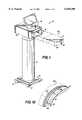
- FIG. 1is an exploded perspective view of an afterloader apparatus illustrating one embodiment of a replaceable sourcewire cartridge for use in the afterloader;
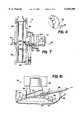
- FIG. 2is a top plan view partly in cross-section of the replaceable cartridge of FIG. 1 illustrating the manner of engagement between the cartridge components and the components of the afterloader apparatus;
- FIG. 3is a partial top plan view, partly in cross-section, of the afterloader apparatus showing the primary drive system and emergency retract system engaged with the drive components of the replaceable cartridge;
- FIG. 4is a fragmentary side elevation view of the emergency retract system taken along line 4--4 of FIG. 3 showing the emergency retract system in its disengaged position;
- FIG. 5is a fragmentary side elevation view of the emergency retract system taken along line 4--4 of FIG. 3 showing the emergency retract system in its engaged position;
- FIG. 6is a fragmentary side elevation view of the primary drive system engaged with the dummy wire drive
- FIG. 7is a side view, partly in cross-section, of the dummy drive taken along line 7--7 of FIG. 2 showing the grooved dummy wire drum and the limit stop mechanism for the dummy wire drum;
- FIG. 8is a perspective view of a washer of the limit stop mechanism of FIG. 7;
- FIG. 9is a cross-sectional detail view of the double slide wire guide mechanism for the active drive taken along line 9--9 of FIG. 2;
- FIG. 10is a fragmentary cross-sectional view taken along line 10--10 of FIG. 9 showing the details of the wire slide mechanism
- FIG. 11is a fragmentary view shown as detail A--A in FIG. 7 illustrating the engagement between the rollers and the wire in the groove of the dummy storage and drive drum;
- FIG. 12is a fragmentary perspective view of one of the wire drums showing the manner in which a wire is anchored to the drum.
- FIG. 1an embodiment of an afterloader apparatus which is designated generally by reference numeral 10.
- Afterloader apparatus 10comprises a base 12 which is preferably wheeled, a pedestal 14 and a head 16 which is vertically adjustable with respect to the pedestal 14 by means of an adjustment mechanism (not shown).
- An appropriate handle(not shown) may be mounted to the base or pedestal for use in positioning the apparatus 10 in a desired location.
- the head 16may support a video monitor screen 18, such as an LCD touch screen display or the like.
- the front or forward end of the head 16is provided with a receptacle opening 19 for removably receiving a replaceable cartridge or cassette 20.
- the cartridge 20comprises a housing 21 with a sourcewire opening 22 in the front wall 24 thereof.
- the cartridge 20contains two elongate wires, namely, an active sourcewire and a dummy test wire, each stored on a respective storage/drive drum, a radiation shield or safe and necessary sensing, monitoring and software components of the system.
- Replaceable cartridges 20are preferably provided by the afterloader manufacturer or its distributor with all components loaded and tested so that when a cartridge is inserted into the receptacle opening 19 and mechanically and electrically engaged with the mating system connections in the head 16, the afterloader apparatus is ready for use in a medical procedure.
- the cartridge 20also contains the system software so that software updates are automatically provided with each exchange of a cartridge.
- the afterloader apparatuscontains a rewritable non-volatile program memory which is updated by the cartridge software.
- the replaceable cartridge of the inventionpermits the user to readily and safely exchange sourcewires as required by decay of the radioactive source without the assistance of highly skilled technicians.
- FIGS. 2 and 3are top views of the head 16 and the cartridge 20 illustrating the manner in which the cartridge is inserted into the receptacle opening 19 of the head in the direction of the arrow B (FIG. 2).
- the head 16has a space or cavity 26 formed in part by side walls 28, 30 and end wall 32.
- a pair of tapered engagement pins 34are mounted to the end wall 32 for mechanically engaging in a corresponding pair of holes 36 in the rear wall 25 of the cartridge and locating the cartridge in position as shown in FIG. 3.
- An electrical connection (not shown) between the cartridge electrical components and the electrical components of the afterloader control system (not shown) in the headis also made when the cartridge is fully inserted into the space 26.
- a sensor and indicatormay be provided for sensing when the cartridge 20 is fully engaged both mechanically and electrically into the head.
- the primary drive system 38comprises a primary drive motor 42 with a vertically oriented output shaft 44 and spur gear 46 for driving a main drive gear 48 through an idle gear 50.
- Drive gear 48is rotatably mounted at one end of an engagement arm 52 which is pivotable about the axis of the output shaft 44 of the drive motor 42 at a point intermediate the ends of the arm 52.
- the rear wall 32 of the headhas a central opening 33 for receiving the drive gear 48 and arm 52 when the cartridge 20 is placed fully inserted into the head 16 as shown in FIG. 3.
- the drive gearWhen the cartridge 20 is fully inserted, the drive gear is located in a neutral position between the dummy drive unit 54 and the active drive unit 56 in the cartridge, but is not drivingly engaged with either unit upon insertion.
- Spring-biased plungers 53, 55maintain the arm 52 in the neutral position.
- the other end 58 of the engagement arm 52is connected to a pair of solenoids 60, 62 by an actuating rod 57.
- the solenoidscomprise a dummy drive solenoid 60 and an active drive solenoid 62 which pull the end 58 of arm 52 via rod 57 in opposite first and second directions, respectively, to pivot arm 52 about shaft 44 and thereby engage the drive gear 48 with either the dummy drive unit 54 or the active drive unit 56 as shown and described hereinafter in connection with FIG. 6.
- a power supply board 64(FIG. 2) for the primary drive system 38 is mounted in the housing above the active drive solenoid 62.
- a brake 65is provided on the dummy drive unit 54 to hold the dummy wire in the park or retracted position except during a treatment.
- the emergency retract system 40is used to retract the active sourcewire from a catheter either by means of battery power or manually in the event of a power failure or primary drive failure. Emergency retraction is necessary to avoid a radioactive overdose of the patient and operating personnel.
- System 40comprises a battery-powered retract motor 66 with a vertically oriented shaft 68 upon which a spur gear 70 is mounted for driving a main gear 72.
- Main gear 72meshes with retract gear assembly 74 mounted in the cartridge 20 when the cartridge is inserted into the head.
- An opening 35 (FIG. 3) in rear wall 32 of the cartridgeaccommodates main gear 72 and permits it to engage with retract gear assembly 74.
- the retract motor 66 and main gear 72are mounted on a plate 76 which is pivotable about the axis of a rotatable shaft 78. Plate 76 is forced by a spring 80 to rotate clockwise about shaft 78 so that gear 72 is biased into meshing engagement with retract gear assembly 74. A further gear 82 is mounted to shaft 78 and meshes with main gear 72. Shaft 78 extends through the top of housing 16 and is provided at its upper free end with a hand wheel (not shown) for manually retracting the sourcewire in the event of failure of both the primary drive system 38 and the emergency retract system 40.
- a retract solenoid 84operates a disengagement lever 86 to disengage the emergency retract system 40 from the active drive unit 56 only during a treatment of a patient. At all other times, including when there is a power failure or a drive failure, solenoid 84 is deenergized so that the emergency drive system is engaged with the active drive unit 56. Operation of the emergency retract system 40 is described in more detail hereinafter in connection with FIGS. 4 and 5.
- the cartridge 20also houses take-off mechanisms 88, 90 for the dummy wire (not shown) and the active sourcewire (not shown), respectively.
- take-off mechanisms 88, 90for the dummy wire (not shown) and the active sourcewire (not shown), respectively.
- each wireis taken off the storage drive of its respective drive unit, it passes through a respective take-off tube 92, 94.
- Each take-off tube 92, 94engages in a respective pivot block 96, 98 from which the wires are guided into separate, parallel passages in a radiation safe or source shield 100 by tubes 102, 104.
- a shutter mechanism 106is provided on the outward end of shield 100 and includes a shutter 108 with a passage (not shown) and a shutter actuator 110 for positioning the shutter passage to connect either the active sourcewire or the dummy wire to the catheter path.
- a tube 112connects the shutter passage to a home sensor unit 114 which precisely locates the distal tip of the dummy wire or active sourcewire.
- the home sensor unit 114may include an optical, mechanical, inductive, capacitive or magnetic sensor which produces an output to the afterloader control system when the distal tip passes the home sensor unit either upon extension or retraction. Upon extension, the amount of wire extended can be measured and upon retraction, it can be determined that the entire wire has been retracted and that no wire breaks have occurred.
- a radiation detector 115such as a solid state radiation detector, is embedded in the radiation safe 100.
- the detector 115provides a coarse validation of the source activity.
- the detector operationcan be checked by observing a drop in the output of the detector.
- the detector 115provides an indication that the entire source has been retracted to its proper position in the safe 100 and has not, for example, broken off in the catheter.
- the detectormay also be used to verify source decay calculations made by the control electronics.
- a catheter receiver assembly 116is mounted to the inside front wall 24 of the housing 21. Assembly 116 receives and locks the catheter in place and provides a signal to the afterloader control system indicating that the catheter is attached to the cartridge.
- the catheter receiver assembly 116also contains a scanner and electronics for decoding machine readable information on the catheter so that such information can be inputted into the afterloader control system as described in the aforesaid copending U.S. patent application Ser. No. 08/436,075.
- the catheter receiver assembly 116may be connected to a force sensor 118 for sensing the force applied to the catheter by the wire during insertion of the wire. This sensed force may be used to control the insertion and insertion rate of the wire as described in the aforesaid copending U.S. patent application Ser. No. 08/436,075.
- Retract gear assembly 74is mounted in a unidirectional bearing 75 so as to permit rotation in only one direction, namely, the direction for withdrawing or retracting the active sourcewire from the catheter.
- the retract gear assembly 74includes first and second retract gears 77, 79 with gear 79 splined to gear 77 so as to be axially (vertically) movable with respect thereto.
- gear 79is at its uppermost axial position disengaged from the retract reel gear 81 of the active drive unit 56.
- gear 79is at its lowermost axial position engaged with the retract reel gear 81.
- the gear 79is fixedly mounted to a shaft 83 which may be spring-biased downwardly so as to urge the gear 79 toward its engaged position with retract reel gear 81.
- the retract solenoid 84is energized since power is applied to the afterloader and a treatment is being performed.
- the plunger 85 of the solenoid 84pushes downwardly on the disengagement lever 86 which rotates counterclockwise about pivot pin 87 as viewed in FIG. 4, and forces drive pin 89 upwardly into engagement with shaft 83 thereby disengaging gear 79 from gear 81.
- the emergency retract system 40will remain in the position shown in FIG. 4 disengaged from the active drive unit 56. Should power be lost to the afterloader, or when no treatment is being performed, the solenoid 84 will be deenergized thus permitting the plunger 85 to retract to the position shown in FIG. 5.
- the disengagement lever 86rotates clockwise about pivot pin 87 lowering drive pin 89 and permitting shaft 83 to move axially downwardly (optionally under the force of a spring) so that gear 79 of the retract gear assembly 74 engages with gear 81.
- the battery(not shown) which supplies power to emergency retract motor 66 is automatically connected to the motor 66 by a solenoid switch or the like to cause the motor to rotate gear train 70, 72, 77, 79, 81 and retract the sourcewire from the catheter in the body of the patient.
- the afterloader operatormay use the manual handwheel attached to shaft 78 to rotate gear train 82, 72, 77, 79, 81 and manually retract the sourcewire from the catheter.
- the unidirectional bearing 75locks the drive in the fully retracted position at all times except during a treatment and also prevents manual operation of the emergency retract system in a direction to advance the sourcewire further into the catheter.
- FIGS. 3 and 6illustrate the manner in which the primary drive system 38 is connected to the dummy drive unit 54 which is substantially identical to the drive system connection to the active drive unit so that only one such connection need be described.
- the drive gear 48With the cartridge 20 fully inserted into the head 16, the drive gear 48 is disposed in a neutral position between the primary reel gears 120 of the drive units 54, 56.
- solenoid 60When it is desired to drive the dummy drive unit 54, for example, solenoid 60 is energized which urges the end 58 of arm 52 upwardly as viewed in FIG. 3 and the gear 48 downwardly into engagement with gear 120.
- Gear 120is secured to the end of the drive shaft 122 for the dummy wire drive drum 124 which is shown and described in greater detail in connection with FIG. 6.
- gear train 46, 50, 48, 120rotates the dummy wire drum 124 to advance the dummy wire contained in the groove on the periphery of the drum 124 through tube 92 and into the catheter.
- gear train 46, 50, 48, 120rotates the drum 124 in the opposite direction to retract the dummy wire into the groove.
- An electromechanical limit stop mechanism 126is provided for limiting the number of revolutions of the drive drum 124 and therefore the maximum length of wire advanced into the catheter. The operation of the limit stop mechanism 126 is described in more detail hereinafter in connection with the description of FIGS. 7 and 8.
- the drive shaft 122is coupled to an encoder 128 which detects the incremental length of wire advanced from or retracted to the drum 124.
- a motor current sensor 130may also be provided for sensing the current applied to the drive motor 42. Such sensor may be used to control the force applied to the sourcewire or dummy wire during advancement thereof in the manner described in copending U.S. patent application Ser. No. 08/436,075.
- the cartridge 20also includes an internal electronics board 123 which contains software from which the afterloader control system boots and which updates the control system software, e.g., a rewritable, non-volatile program memory, contained in the afterloader head 16.
- control system softwaree.g., a rewritable, non-volatile program memory
- FIGS. 7-12illustrate the dummy drive unit 54 in greater detail. It should be understood that the dummy drive unit 54 and the active unit 56 are substantially identical in construction and operation and any significant differences will be specifically described herein.
- Drive unit 54comprises drive drum 124 having a diameter of about 3 inches and a helical groove or thread 125 machined in the periphery thereof for storing a flexible wire W having a diameter of about 0.020 inch.
- the drum 124is fixedly mounted on drive shaft 122 which is rotatably mounted in a pair of double or redundant bearings 132, 134 for rotation about the vertical axis of shaft 122.
- Double bearings 132, 134are supported in a pair of plates 136, 138 which are mounted in the cartridge 20 in fixed, spaced relationship to one another by a plurality of posts (not shown). Double bearings are preferably used for each bearing 132, 134 so that if one of the bearings of a double being should fail, the drive will continue to function normally.
- the wire Wis contained in the helical groove 125 by a plurality of low friction elements such as rollers 140 (FIG. 11) which surround the drum 124 over substantially its entire circumference.
- the rollers 140provide a low friction containment of the wire W in groove 125 such that, as the drum rotates in a direction to advance the wire into the catheter (i.e., unwinds the wire from the drum), the wire expands outwardly against the rollers 140.
- the proximal end 141 of the wire Wis anchored to the drum along one face 142 thereof (FIG. 12) and enters the helical groove 125 from an arcuate groove 144 in face 142.
- the driving force of the drum 124 on the wire Wacts from the proximal end 141 thereof and thus places the wire in compression along its entire length when the wire is driven into the catheter (i.e., unwound from the drum).
- the rollers 140completely contain the wire W in the groove 125 with little or no slack in the wire along its path. Such tight containment of the wire positively prevents spillage of the wire from the drum which was possible in prior art belt drives.
- Mechanism 90comprises a slider block 148 made of a low friction material, such as UHMW plastic, which replaces several of the rollers 140.
- a hole 150 having a diameter slightly larger than the diameter of the wire Wis drilled through the slider 148 along an axis tangential to the periphery of the drum 124.
- the slider 148is mounted in a linear bearing 146 which permits the slider 148 to be moved by the wire W so that the slider 148 follows the helical groove 125 transversely across the drum periphery.
- One suitable linear bearingis made by the PIC Company of Middlebury, Conn.
- the slider 148is supported in a pair of linear bearings 146, 152 (FIG. 2) so that if one of the bearings should seize or otherwise fail, the other bearing will still permit the slider to move under the force of the wire being payed off the drum.
- the dummy drive unit 54has only a single linear bearing 146 although two such bearings could be provided if desired.
- Take-off pivot tube 94engages in a tapered bore 156 of the slider 148 so that as the slider moves across the drum periphery, the take-off tube 94 pivots in the bore 156 as the slider 148 follows the helical groove 125 in the drum.
- the take-off tube 94also pivots with respect to a tapered bore (not shown) in pivot block 98 from which the wire W passes through tube 104, shield 100 and tube 112 into the catheter receiver 116.
- the wire take-off mechanism 88 for the dummy drive unit 54operates in the same way as take-off mechanism 90 for the active drive unit 56.
- the limit stop mechanism 126(FIG. 7) comprises a stack of washers 160 each having an overhanging tang or tab 162 and a central bore 164 (FIG. 8).
- a bearing sleeve(not shown) is provided on the shaft 122 for receiving the bores 164 of the washers so that undesired lockup between the washers will not seize the drive shaft 122.
- the washers 160are stacked on a switch lever 166 which is rotatably mounted on the bearing sleeve of shaft 122.
- Lever 166has a lever arm 168 which engages the tang 162a of the lower most washer 160a.
- An upper stop cap 170is fixed to the upper end of the shaft 122 by means of set screws 172 and is provided with an overhanging tang (not shown) which engages the tang 162b of the uppermost washer 160b.
- the tangs 162engage one another seriatim from tang 162b to tang 162a.
- Tang 162aengages the lever arm 168 of switch lever 166 to rotate against spring force until one of a pair of microswitches 174 is operated.
- Each microswitch 174transmits a signal to the afterloader control system electronics to indicate that the wire W has reached the limit of its travel in that direction or to control the primary drive system 38. It will be appreciated by those skilled in the art that the stop positions for advancing and retracting the wire W can be adjusted for any given or desired wire length by varying the number of washers 160 on the shaft and by adjusting the angular position of the overhanging tang on the upper stop cap 170.
Landscapes
- Health & Medical Sciences (AREA)
- Engineering & Computer Science (AREA)
- Biomedical Technology (AREA)
- Pathology (AREA)
- Nuclear Medicine, Radiotherapy & Molecular Imaging (AREA)
- Radiology & Medical Imaging (AREA)
- Life Sciences & Earth Sciences (AREA)
- Animal Behavior & Ethology (AREA)
- General Health & Medical Sciences (AREA)
- Public Health (AREA)
- Veterinary Medicine (AREA)
- Radiation-Therapy Devices (AREA)
- Media Introduction/Drainage Providing Device (AREA)
Abstract
Description
Claims (12)
Priority Applications (6)
| Application Number | Priority Date | Filing Date | Title |
|---|---|---|---|
| US08/888,332US6048300A (en) | 1997-07-03 | 1997-07-03 | Compact cartridge for afterloader |
| EP98933162AEP1015067A4 (en) | 1997-07-03 | 1998-07-06 | Compact cartridge for afterloader and method |
| JP2000500936AJP2001509406A (en) | 1997-07-03 | 1998-07-06 | Compact cartridge and method for afterloader |
| PCT/US1998/013924WO1999001174A1 (en) | 1997-07-03 | 1998-07-06 | Compact cartridge for afterloader and method |
| AU82888/98AAU8288898A (en) | 1997-07-03 | 1998-07-06 | Compact cartridge for afterloader and method |
| CA002295985ACA2295985A1 (en) | 1997-07-03 | 1998-07-06 | Compact cartridge for afterloader and method |
Applications Claiming Priority (1)
| Application Number | Priority Date | Filing Date | Title |
|---|---|---|---|
| US08/888,332US6048300A (en) | 1997-07-03 | 1997-07-03 | Compact cartridge for afterloader |
Publications (1)
| Publication Number | Publication Date |
|---|---|
| US6048300Atrue US6048300A (en) | 2000-04-11 |
Family
ID=25392989
Family Applications (1)
| Application Number | Title | Priority Date | Filing Date |
|---|---|---|---|
| US08/888,332Expired - LifetimeUS6048300A (en) | 1997-07-03 | 1997-07-03 | Compact cartridge for afterloader |
Country Status (6)
| Country | Link |
|---|---|
| US (1) | US6048300A (en) |
| EP (1) | EP1015067A4 (en) |
| JP (1) | JP2001509406A (en) |
| AU (1) | AU8288898A (en) |
| CA (1) | CA2295985A1 (en) |
| WO (1) | WO1999001174A1 (en) |
Cited By (36)
| Publication number | Priority date | Publication date | Assignee | Title |
|---|---|---|---|---|
| WO2000037137A1 (en)* | 1998-12-22 | 2000-06-29 | Novoste Corporation | Automated system for the radiation treatment of a desired area within the body of a patient |
| US6302865B1 (en) | 2000-03-13 | 2001-10-16 | Scimed Life Systems, Inc. | Intravascular guidewire with perfusion lumen |
| WO2001093945A2 (en) | 2000-06-05 | 2001-12-13 | Mentor Corporation | Automated radioisotope seed cartridge |
| US6350227B1 (en) | 1997-09-23 | 2002-02-26 | Interventional Therapies, Llc | Afterloader apparatus |
| WO2002018013A1 (en)* | 2000-08-28 | 2002-03-07 | Isotron, Inc. | Remote afterloader |
| US6416457B1 (en) | 2000-03-09 | 2002-07-09 | Scimed Life Systems, Inc. | System and method for intravascular ionizing tandem radiation therapy |
| US20020099255A1 (en)* | 1997-09-23 | 2002-07-25 | Liprie Sam F. | Afterloader apparatus |
| US6471979B2 (en) | 1999-12-29 | 2002-10-29 | Estrogen Vascular Technology, Llc | Apparatus and method for delivering compounds to a living organism |
| US20030018232A1 (en)* | 2000-06-05 | 2003-01-23 | Mentor Corporation | Automated implantation system for radioisotope seeds |
| US6537192B1 (en) | 2000-06-05 | 2003-03-25 | Mentor Corporation | Automated radioisotope seed loader system for implant needles |
| US6582352B2 (en) | 1994-06-10 | 2003-06-24 | Schneider (Europe) A.G. | Medical appliance for treatment by ionizing radiation |
| US6585634B1 (en) | 2001-04-17 | 2003-07-01 | Advanced Cardiovascular Systems, Inc. | Force sensing mechanism |
| US6585684B1 (en) | 1998-12-22 | 2003-07-01 | Novoste Corporation | Automated system for the radiation treatment of a desired area within the body of a patient |
| US20030128808A1 (en)* | 2001-11-23 | 2003-07-10 | Johann Kindlein | Device for effecting radiation therapy in an animal body |
| US6599230B2 (en) | 1996-02-29 | 2003-07-29 | Scimed Life Systems, Inc. | Intravascular radiation delivery system |
| US6616629B1 (en) | 1994-06-24 | 2003-09-09 | Schneider (Europe) A.G. | Medical appliance with centering balloon |
| EP1348464A1 (en) | 2002-03-27 | 2003-10-01 | Nucletron B.V. | After loader apparatus as well as a device for exchanging an after loader cartridge. |
| US6730013B1 (en)* | 1999-04-09 | 2004-05-04 | Medi-Physics, Inc. | Method and apparatus for loading delivery systems for brachytherapy seeds |
| EP1445002A1 (en)* | 2003-02-05 | 2004-08-11 | Nucletron B.V. | Source wire position sensing device for an afterloader |
| NL1028428C2 (en)* | 2005-02-28 | 2006-08-29 | Isodose Control Intellectual P | Storage container. |
| US20070265485A1 (en)* | 2001-02-22 | 2007-11-15 | Dejuan Eugene Jr | Beta radiotherapy emitting surgical device and methods of use thereof |
| US20070276216A1 (en)* | 2004-08-16 | 2007-11-29 | Refael Beyar | Image-Guided Navigation for Catheter-Based Interventions |
| US20090131955A1 (en)* | 2005-09-29 | 2009-05-21 | Corindus Ltd. | Methods and apparatuses for treatment of hollow organs |
| US20090221958A1 (en)* | 2005-05-10 | 2009-09-03 | Rafael Beyar | User interface for remote control catheterization |
| WO2009137410A1 (en)* | 2008-05-06 | 2009-11-12 | Corindus Ltd. | Catheter system |
| WO2009149175A1 (en)* | 2008-06-04 | 2009-12-10 | Neovista, Inc. | Handheld radiation delivery system for advancing a radiation source wire |
| US20110144658A1 (en)* | 2008-08-29 | 2011-06-16 | Corindus Inc. | Catheter simulation and assistance system |
| US20110152882A1 (en)* | 2008-08-29 | 2011-06-23 | Corindus Inc. | Catheter control system and graphical user interface |
| US20110238082A1 (en)* | 2008-12-12 | 2011-09-29 | Corindus Inc. | Remote catheter procedure system |
| US20120035596A1 (en)* | 2010-08-04 | 2012-02-09 | Tegg Troy T | Disposable Drive Interface for Longitudinal Movement of an Elongate Medical Device |
| US20120179167A1 (en)* | 2010-09-17 | 2012-07-12 | Corindus Inc. | Robotic catheter system |
| US8790297B2 (en) | 2009-03-18 | 2014-07-29 | Corindus, Inc. | Remote catheter system with steerable catheter |
| US9220568B2 (en) | 2009-10-12 | 2015-12-29 | Corindus Inc. | Catheter system with percutaneous device movement algorithm |
| US9962229B2 (en) | 2009-10-12 | 2018-05-08 | Corindus, Inc. | System and method for navigating a guide wire |
| WO2021155099A1 (en)* | 2020-01-31 | 2021-08-05 | University Of Iowa Research Foundation | Modular remote afterloader for brachytherapy delivery and cartridge for same |
| US11918314B2 (en) | 2009-10-12 | 2024-03-05 | Corindus, Inc. | System and method for navigating a guide wire |
Families Citing this family (1)
| Publication number | Priority date | Publication date | Assignee | Title |
|---|---|---|---|---|
| US20100010505A1 (en)* | 2008-07-11 | 2010-01-14 | Herlihy J Patrick | Methods and apparatus for introducing a medical device into the body of a patient |
Citations (5)
| Publication number | Priority date | Publication date | Assignee | Title |
|---|---|---|---|---|
| US3638524A (en)* | 1970-07-17 | 1972-02-01 | Quaker Oats Co | Multitune music box |
| US4631415A (en)* | 1983-09-30 | 1986-12-23 | Kurt Sauerwein | Radiation treatment apparatus |
| US4881937A (en)* | 1986-07-10 | 1989-11-21 | Eric van't Hooft | Method of treating a part of the body with radioactive material and a trolley for use therein |
| US5092834A (en)* | 1990-10-12 | 1992-03-03 | Omnitron International, Inc. | Apparatus and method for the remote handling of highly radioactive sources in the treatment of cancer |
| US5503041A (en)* | 1992-06-25 | 1996-04-02 | B.V. Optische Industrie "De Oude Delft" | Apparatus for connecting a first end part of a cable to a drive unit |
Family Cites Families (3)
| Publication number | Priority date | Publication date | Assignee | Title |
|---|---|---|---|---|
| CN1026755C (en)* | 1991-08-17 | 1994-11-30 | 王力平 | Internal radiotherapy method and device for human body |
| US5851172A (en)* | 1995-05-08 | 1998-12-22 | Omnitron International, Inc. | Afterloader with active force feedback |
| DE19525811A1 (en)* | 1995-07-15 | 1997-01-16 | Sauerwein Isotopen Tech | X=ray image system with varying pixel supply voltages for zoom control - uses amorphous silicon photodiode detectors with means for choice of different image recording speed and corresp. resolution |
- 1997
- 1997-07-03USUS08/888,332patent/US6048300A/ennot_activeExpired - Lifetime
- 1998
- 1998-07-06CACA002295985Apatent/CA2295985A1/ennot_activeAbandoned
- 1998-07-06EPEP98933162Apatent/EP1015067A4/ennot_activeCeased
- 1998-07-06WOPCT/US1998/013924patent/WO1999001174A1/ennot_activeApplication Discontinuation
- 1998-07-06AUAU82888/98Apatent/AU8288898A/ennot_activeAbandoned
- 1998-07-06JPJP2000500936Apatent/JP2001509406A/enactivePending
Patent Citations (6)
| Publication number | Priority date | Publication date | Assignee | Title |
|---|---|---|---|---|
| US3638524A (en)* | 1970-07-17 | 1972-02-01 | Quaker Oats Co | Multitune music box |
| US4631415A (en)* | 1983-09-30 | 1986-12-23 | Kurt Sauerwein | Radiation treatment apparatus |
| US4881937A (en)* | 1986-07-10 | 1989-11-21 | Eric van't Hooft | Method of treating a part of the body with radioactive material and a trolley for use therein |
| US5030194A (en)* | 1986-07-10 | 1991-07-09 | Eric van't Hooft | Method and apparatus for effecting radioactive therapy in an animal body |
| US5092834A (en)* | 1990-10-12 | 1992-03-03 | Omnitron International, Inc. | Apparatus and method for the remote handling of highly radioactive sources in the treatment of cancer |
| US5503041A (en)* | 1992-06-25 | 1996-04-02 | B.V. Optische Industrie "De Oude Delft" | Apparatus for connecting a first end part of a cable to a drive unit |
Cited By (90)
| Publication number | Priority date | Publication date | Assignee | Title |
|---|---|---|---|---|
| US6582352B2 (en) | 1994-06-10 | 2003-06-24 | Schneider (Europe) A.G. | Medical appliance for treatment by ionizing radiation |
| US6616629B1 (en) | 1994-06-24 | 2003-09-09 | Schneider (Europe) A.G. | Medical appliance with centering balloon |
| US6599230B2 (en) | 1996-02-29 | 2003-07-29 | Scimed Life Systems, Inc. | Intravascular radiation delivery system |
| EP1331971A4 (en)* | 1997-09-23 | 2006-03-08 | Interventional Therapies Llc | Afterloader apparatus |
| US20040162459A1 (en)* | 1997-09-23 | 2004-08-19 | Liprie Sam F. | Afterloader apparatus |
| US6350227B1 (en) | 1997-09-23 | 2002-02-26 | Interventional Therapies, Llc | Afterloader apparatus |
| US20020099255A1 (en)* | 1997-09-23 | 2002-07-25 | Liprie Sam F. | Afterloader apparatus |
| US7066873B2 (en) | 1998-12-22 | 2006-06-27 | Best Vascular, Inc. | Automated system for the radiation treatment of a desired area within the body of a patient |
| US6659934B1 (en) | 1998-12-22 | 2003-12-09 | Novoste Corporation | Automated system for the radiation treatment of a desired area within the body of a patient |
| WO2000037137A1 (en)* | 1998-12-22 | 2000-06-29 | Novoste Corporation | Automated system for the radiation treatment of a desired area within the body of a patient |
| US7311656B2 (en) | 1998-12-22 | 2007-12-25 | Best Vascular, Inc. | Automated system for the radiation treatment of a desired area within the body of a patient |
| US6585684B1 (en) | 1998-12-22 | 2003-07-01 | Novoste Corporation | Automated system for the radiation treatment of a desired area within the body of a patient |
| US20040097778A1 (en)* | 1998-12-22 | 2004-05-20 | Novoste Corporation | Automated system for the radiation treatment of a desired area within the body of a patient |
| US20040092787A1 (en)* | 1998-12-22 | 2004-05-13 | Novoste Corporation | Automated system for the radiation treatment of a desired area within the body of a patient |
| US6730013B1 (en)* | 1999-04-09 | 2004-05-04 | Medi-Physics, Inc. | Method and apparatus for loading delivery systems for brachytherapy seeds |
| US6863658B2 (en) | 1999-12-22 | 2005-03-08 | Novoste Corporation | Automated system for the radiation treatment of a desired area within the body of a patient |
| US20040044305A1 (en)* | 1999-12-22 | 2004-03-04 | Novoste Corporation | Automated system for the radiation treatment of a desired area within the body of a patient |
| US6471979B2 (en) | 1999-12-29 | 2002-10-29 | Estrogen Vascular Technology, Llc | Apparatus and method for delivering compounds to a living organism |
| US6416457B1 (en) | 2000-03-09 | 2002-07-09 | Scimed Life Systems, Inc. | System and method for intravascular ionizing tandem radiation therapy |
| US6302865B1 (en) | 2000-03-13 | 2001-10-16 | Scimed Life Systems, Inc. | Intravascular guidewire with perfusion lumen |
| US6599231B1 (en) | 2000-06-05 | 2003-07-29 | Mentor Corporation | Loading clip for radioisotope seeds |
| US20030018232A1 (en)* | 2000-06-05 | 2003-01-23 | Mentor Corporation | Automated implantation system for radioisotope seeds |
| US7959548B2 (en) | 2000-06-05 | 2011-06-14 | Core Oncology, Inc. | Automated implantation system for radioisotope seeds |
| US20050209499A1 (en)* | 2000-06-05 | 2005-09-22 | Mentor Corporation | Automated implantation system for radioisotope seeds |
| US6616593B1 (en) | 2000-06-05 | 2003-09-09 | Mentor Corporation | Automated radioisotope seed cartridge |
| US6869390B2 (en) | 2000-06-05 | 2005-03-22 | Mentor Corporation | Automated implantation system for radioisotope seeds |
| US20030139641A1 (en)* | 2000-06-05 | 2003-07-24 | Mentor Corporation | Automated radioisotope seed loader system for implant needles |
| US7229400B2 (en) | 2000-06-05 | 2007-06-12 | Mills Biopharmaceuticals Llc | Automated radioisotope seed loader system for implant needles |
| WO2001093945A2 (en) | 2000-06-05 | 2001-12-13 | Mentor Corporation | Automated radioisotope seed cartridge |
| US6537192B1 (en) | 2000-06-05 | 2003-03-25 | Mentor Corporation | Automated radioisotope seed loader system for implant needles |
| US6497645B1 (en)* | 2000-08-28 | 2002-12-24 | Isotron, Inc. | Remote afterloader |
| WO2002018013A1 (en)* | 2000-08-28 | 2002-03-07 | Isotron, Inc. | Remote afterloader |
| US8100818B2 (en) | 2001-02-22 | 2012-01-24 | TDH Partners, Inc. | Beta radiotherapy emitting surgical device and methods of use thereof |
| US20070265485A1 (en)* | 2001-02-22 | 2007-11-15 | Dejuan Eugene Jr | Beta radiotherapy emitting surgical device and methods of use thereof |
| US6585634B1 (en) | 2001-04-17 | 2003-07-01 | Advanced Cardiovascular Systems, Inc. | Force sensing mechanism |
| US7252629B2 (en)* | 2001-11-23 | 2007-08-07 | Nucletron B.V. | Device for effecting radiation therapy in an animal body |
| US20030128808A1 (en)* | 2001-11-23 | 2003-07-10 | Johann Kindlein | Device for effecting radiation therapy in an animal body |
| AU2003202531B2 (en)* | 2002-03-27 | 2007-07-05 | Nucletron B.V. | After loader apparatus, cartridge as well as a device for exchanging an after loader cartridge |
| EP1348464A1 (en) | 2002-03-27 | 2003-10-01 | Nucletron B.V. | After loader apparatus as well as a device for exchanging an after loader cartridge. |
| US7097609B2 (en) | 2002-03-27 | 2006-08-29 | Nucletron B.V. | After loader apparatus as well as a device for exchanging an after loader cartridge |
| US20040024284A1 (en)* | 2002-03-27 | 2004-02-05 | Johann Kindlein | After loader apparatus as well as a device for exchanging an after loader cartridge |
| US7510520B2 (en) | 2003-02-05 | 2009-03-31 | Nucletron B.V. | Device for sensing distal end of source wire in an afterloader |
| EP1445002A1 (en)* | 2003-02-05 | 2004-08-11 | Nucletron B.V. | Source wire position sensing device for an afterloader |
| US20070276216A1 (en)* | 2004-08-16 | 2007-11-29 | Refael Beyar | Image-Guided Navigation for Catheter-Based Interventions |
| US8600477B2 (en) | 2004-08-16 | 2013-12-03 | Corinduc, Inc. | Image-guided navigation for catheter-based interventions |
| EP1695739A1 (en)* | 2005-02-28 | 2006-08-30 | Isodose Control B.V. | Storage container |
| NL1028428C2 (en)* | 2005-02-28 | 2006-08-29 | Isodose Control Intellectual P | Storage container. |
| US20090221958A1 (en)* | 2005-05-10 | 2009-09-03 | Rafael Beyar | User interface for remote control catheterization |
| US8257302B2 (en) | 2005-05-10 | 2012-09-04 | Corindus, Inc. | User interface for remote control catheterization |
| US20090131955A1 (en)* | 2005-09-29 | 2009-05-21 | Corindus Ltd. | Methods and apparatuses for treatment of hollow organs |
| US8828021B2 (en) | 2008-05-06 | 2014-09-09 | Corindus, Inc. | Catheter system |
| US10987491B2 (en) | 2008-05-06 | 2021-04-27 | Corindus, Inc. | Robotic catheter system |
| US20100076310A1 (en)* | 2008-05-06 | 2010-03-25 | Corindus Ltd. | Catheter system |
| US7887549B2 (en) | 2008-05-06 | 2011-02-15 | Corindus Inc. | Catheter system |
| US9623209B2 (en) | 2008-05-06 | 2017-04-18 | Corindus, Inc. | Robotic catheter system |
| EP3406291B1 (en) | 2008-05-06 | 2019-12-04 | Corindus Inc. | Catheter system |
| US9402977B2 (en) | 2008-05-06 | 2016-08-02 | Corindus Inc. | Catheter system |
| JP2011519678A (en)* | 2008-05-06 | 2011-07-14 | コリンダス インコーポレイテッド | Catheter system |
| US9168356B2 (en) | 2008-05-06 | 2015-10-27 | Corindus Inc. | Robotic catheter system |
| WO2009137410A1 (en)* | 2008-05-06 | 2009-11-12 | Corindus Ltd. | Catheter system |
| EP4268758A3 (en)* | 2008-05-06 | 2024-01-03 | Corindus, Inc. | Catheter system |
| US11717645B2 (en) | 2008-05-06 | 2023-08-08 | Corindus, Inc. | Robotic catheter system |
| US20100076308A1 (en)* | 2008-05-06 | 2010-03-25 | Corindus Ltd. | Catheter system |
| US20100076309A1 (en)* | 2008-05-06 | 2010-03-25 | Corindus Ltd. | Catheter system |
| EP3646917B1 (en) | 2008-05-06 | 2021-04-28 | Corindus, Inc | Catheter system |
| US8480618B2 (en) | 2008-05-06 | 2013-07-09 | Corindus Inc. | Catheter system |
| US20100069833A1 (en)* | 2008-05-06 | 2010-03-18 | Corindus Ltd. | Catheter system |
| US9095681B2 (en) | 2008-05-06 | 2015-08-04 | Corindus Inc. | Catheter system |
| USD680645S1 (en) | 2008-05-06 | 2013-04-23 | Corindus Inc. | Catheter system cassette |
| US10342953B2 (en) | 2008-05-06 | 2019-07-09 | Corindus, Inc. | Robotic catheter system |
| US20100030010A1 (en)* | 2008-06-04 | 2010-02-04 | Bill Vermeere | Handheld radiation delivery system |
| US8353812B2 (en) | 2008-06-04 | 2013-01-15 | Neovista, Inc. | Handheld radiation delivery system |
| WO2009149175A1 (en)* | 2008-06-04 | 2009-12-10 | Neovista, Inc. | Handheld radiation delivery system for advancing a radiation source wire |
| US8694157B2 (en) | 2008-08-29 | 2014-04-08 | Corindus, Inc. | Catheter control system and graphical user interface |
| US20110152882A1 (en)* | 2008-08-29 | 2011-06-23 | Corindus Inc. | Catheter control system and graphical user interface |
| US20110144658A1 (en)* | 2008-08-29 | 2011-06-16 | Corindus Inc. | Catheter simulation and assistance system |
| US20110238082A1 (en)* | 2008-12-12 | 2011-09-29 | Corindus Inc. | Remote catheter procedure system |
| US10561821B2 (en) | 2008-12-12 | 2020-02-18 | Corindus, Inc. | Remote catheter procedure system |
| US12171955B2 (en) | 2008-12-12 | 2024-12-24 | Siemens Healthineers Endovascular Robotics Inc | Remote catheter procedure system |
| US9545497B2 (en) | 2008-12-12 | 2017-01-17 | Corindus, Inc. | Remote catheter procedure system |
| US8790297B2 (en) | 2009-03-18 | 2014-07-29 | Corindus, Inc. | Remote catheter system with steerable catheter |
| US10881474B2 (en) | 2009-10-12 | 2021-01-05 | Corindus, Inc. | System and method for navigating a guide wire |
| US9220568B2 (en) | 2009-10-12 | 2015-12-29 | Corindus Inc. | Catheter system with percutaneous device movement algorithm |
| US9962229B2 (en) | 2009-10-12 | 2018-05-08 | Corindus, Inc. | System and method for navigating a guide wire |
| US11696808B2 (en) | 2009-10-12 | 2023-07-11 | Corindus, Inc. | System and method for navigating a guide wire |
| US11918314B2 (en) | 2009-10-12 | 2024-03-05 | Corindus, Inc. | System and method for navigating a guide wire |
| US20120035596A1 (en)* | 2010-08-04 | 2012-02-09 | Tegg Troy T | Disposable Drive Interface for Longitudinal Movement of an Elongate Medical Device |
| US20120179167A1 (en)* | 2010-09-17 | 2012-07-12 | Corindus Inc. | Robotic catheter system |
| US9833293B2 (en)* | 2010-09-17 | 2017-12-05 | Corindus, Inc. | Robotic catheter system |
| WO2021155099A1 (en)* | 2020-01-31 | 2021-08-05 | University Of Iowa Research Foundation | Modular remote afterloader for brachytherapy delivery and cartridge for same |
Also Published As
| Publication number | Publication date |
|---|---|
| WO1999001174A1 (en) | 1999-01-14 |
| EP1015067A4 (en) | 2003-01-08 |
| CA2295985A1 (en) | 1999-01-14 |
| AU8288898A (en) | 1999-01-25 |
| EP1015067A1 (en) | 2000-07-05 |
| JP2001509406A (en) | 2001-07-24 |
Similar Documents
| Publication | Publication Date | Title |
|---|---|---|
| US6048300A (en) | Compact cartridge for afterloader | |
| EP0774994B1 (en) | After loader with active force feedback | |
| US5139473A (en) | Apparatus and method for the remote handling of highly radioactive sources in the treatment of cancer | |
| US5103395A (en) | System for remote positioning of a radioactive source into a patient including means for protection against improper patient exposure to radiation | |
| US5030194A (en) | Method and apparatus for effecting radioactive therapy in an animal body | |
| US4851694A (en) | Device for driving and positioning a source holder in an applicator used in radiotherapy | |
| US5957829A (en) | Apparatus and method for radiotherapy using a radioactive source wire having a magnetic insert | |
| JP2003526485A (en) | Automated system for radiation therapy | |
| US9387343B2 (en) | Apparatus and method for effecting radiation treatment on a pre-selected anatomical portion of an animal body | |
| EP1140274B1 (en) | Automated system for the radiation treatment of a desired area within the body of a patient | |
| US7097609B2 (en) | After loader apparatus as well as a device for exchanging an after loader cartridge | |
| US20240416145A1 (en) | Radioactive source delivery system with a stylet pulling mechanism and its method of use | |
| CA2456845C (en) | Sensing device | |
| WO2000048664A2 (en) | Automatic ribbon delivery system for intravascular radiation therapy | |
| US20020099255A1 (en) | Afterloader apparatus | |
| JPH11276608A (en) | Loading device and feeding method for wire shaped body |
Legal Events
| Date | Code | Title | Description |
|---|---|---|---|
| AS | Assignment | Owner name:GUIDANT CORPORATION, CALIFORNIA Free format text:ASSIGNMENT OF ASSIGNORS INTEREST;ASSIGNORS:THORNTON, RICHARD T.;CALFEE, RICHARD V.;EDISON, JOHN P.;AND OTHERS;REEL/FRAME:008909/0435 Effective date:19970702 | |
| AS | Assignment | Owner name:GUIDANT CORPORATION, CALIFORNIA Free format text:ASSIGNMENT OF ASSIGNORS INTEREST;ASSIGNORS:THORNTON, RICHARD T.;CALFEE, RICHARD V.;EDISON, JOHN P.;AND OTHERS;REEL/FRAME:008717/0386 Effective date:19970702 | |
| STCF | Information on status: patent grant | Free format text:PATENTED CASE | |
| AS | Assignment | Owner name:ADVANCED CARDIOVASCULAR SYSTEMS, INC., CALIFORNIA Free format text:ASSIGNMENT OF ASSIGNORS INTEREST;ASSIGNOR:GUIDANT CORPORATION;REEL/FRAME:010859/0519 Effective date:20000524 | |
| FPAY | Fee payment | Year of fee payment:4 | |
| FPAY | Fee payment | Year of fee payment:8 | |
| FEPP | Fee payment procedure | Free format text:PAYOR NUMBER ASSIGNED (ORIGINAL EVENT CODE: ASPN); ENTITY STATUS OF PATENT OWNER: LARGE ENTITY Free format text:PAYER NUMBER DE-ASSIGNED (ORIGINAL EVENT CODE: RMPN); ENTITY STATUS OF PATENT OWNER: LARGE ENTITY | |
| FPAY | Fee payment | Year of fee payment:12 |