US6048229A - Environmentally resistant EMI rectangular connector having modular and bayonet coupling property - Google Patents
Environmentally resistant EMI rectangular connector having modular and bayonet coupling propertyDownload PDFInfo
- Publication number
- US6048229A US6048229AUS09/363,199US36319999AUS6048229AUS 6048229 AUS6048229 AUS 6048229AUS 36319999 AUS36319999 AUS 36319999AUS 6048229 AUS6048229 AUS 6048229A
- Authority
- US
- United States
- Prior art keywords
- component
- locking pin
- insert
- connector
- onto
- Prior art date
- Legal status (The legal status is an assumption and is not a legal conclusion. Google has not performed a legal analysis and makes no representation as to the accuracy of the status listed.)
- Expired - Lifetime
Links
- 230000001808coupling effectEffects0.000titleclaimsdescription4
- 230000008878couplingEffects0.000claimsabstractdescription40
- 238000010168coupling processMethods0.000claimsabstractdescription40
- 238000005859coupling reactionMethods0.000claimsabstractdescription40
- 230000007246mechanismEffects0.000claimsabstractdescription13
- 230000014759maintenance of locationEffects0.000claimsabstractdescription8
- 238000007789sealingMethods0.000claimsabstractdescription6
- 230000000007visual effectEffects0.000claimsabstract2
- 230000013011matingEffects0.000claimsdescription5
- 230000007613environmental effectEffects0.000claimsdescription4
- 238000000926separation methodMethods0.000claimsdescription4
- 230000006835compressionEffects0.000claimsdescription3
- 238000007906compressionMethods0.000claimsdescription3
- 239000002184metalSubstances0.000claimsdescription3
- 238000000034methodMethods0.000claims3
- 239000012530fluidSubstances0.000claims2
- 238000004804windingMethods0.000claims1
- 238000010276constructionMethods0.000abstractdescription6
- 238000003780insertionMethods0.000abstractdescription2
- 230000037431insertionEffects0.000abstractdescription2
- 230000009977dual effectEffects0.000abstract1
- 239000003550markerSubstances0.000abstract1
- 238000009434installationMethods0.000description3
- 238000012423maintenanceMethods0.000description2
- 230000008030eliminationEffects0.000description1
- 238000003379elimination reactionMethods0.000description1
- 230000002452interceptive effectEffects0.000description1
- 230000010287polarizationEffects0.000description1
- 230000000717retained effectEffects0.000description1
- 230000035939shockEffects0.000description1
Images


Classifications
- H—ELECTRICITY
- H01—ELECTRIC ELEMENTS
- H01R—ELECTRICALLY-CONDUCTIVE CONNECTIONS; STRUCTURAL ASSOCIATIONS OF A PLURALITY OF MUTUALLY-INSULATED ELECTRICAL CONNECTING ELEMENTS; COUPLING DEVICES; CURRENT COLLECTORS
- H01R13/00—Details of coupling devices of the kinds covered by groups H01R12/70 or H01R24/00 - H01R33/00
- H01R13/62—Means for facilitating engagement or disengagement of coupling parts or for holding them in engagement
- H01R13/622—Screw-ring or screw-casing
- H—ELECTRICITY
- H01—ELECTRIC ELEMENTS
- H01R—ELECTRICALLY-CONDUCTIVE CONNECTIONS; STRUCTURAL ASSOCIATIONS OF A PLURALITY OF MUTUALLY-INSULATED ELECTRICAL CONNECTING ELEMENTS; COUPLING DEVICES; CURRENT COLLECTORS
- H01R13/00—Details of coupling devices of the kinds covered by groups H01R12/70 or H01R24/00 - H01R33/00
- H01R13/40—Securing contact members in or to a base or case; Insulating of contact members
- H01R13/42—Securing in a demountable manner
- H01R13/424—Securing in base or case composed of a plurality of insulating parts having at least one resilient insulating part
- H—ELECTRICITY
- H01—ELECTRIC ELEMENTS
- H01R—ELECTRICALLY-CONDUCTIVE CONNECTIONS; STRUCTURAL ASSOCIATIONS OF A PLURALITY OF MUTUALLY-INSULATED ELECTRICAL CONNECTING ELEMENTS; COUPLING DEVICES; CURRENT COLLECTORS
- H01R13/00—Details of coupling devices of the kinds covered by groups H01R12/70 or H01R24/00 - H01R33/00
- H01R13/46—Bases; Cases
- H01R13/52—Dustproof, splashproof, drip-proof, waterproof, or flameproof cases
- H01R13/5205—Sealing means between cable and housing, e.g. grommet
- H01R13/5208—Sealing means between cable and housing, e.g. grommet having at least two cable receiving openings
- H—ELECTRICITY
- H01—ELECTRIC ELEMENTS
- H01R—ELECTRICALLY-CONDUCTIVE CONNECTIONS; STRUCTURAL ASSOCIATIONS OF A PLURALITY OF MUTUALLY-INSULATED ELECTRICAL CONNECTING ELEMENTS; COUPLING DEVICES; CURRENT COLLECTORS
- H01R13/00—Details of coupling devices of the kinds covered by groups H01R12/70 or H01R24/00 - H01R33/00
- H01R13/46—Bases; Cases
- H01R13/52—Dustproof, splashproof, drip-proof, waterproof, or flameproof cases
- H01R13/5219—Sealing means between coupling parts, e.g. interfacial seal
- H01R13/5221—Sealing means between coupling parts, e.g. interfacial seal having cable sealing means
- H—ELECTRICITY
- H01—ELECTRIC ELEMENTS
- H01R—ELECTRICALLY-CONDUCTIVE CONNECTIONS; STRUCTURAL ASSOCIATIONS OF A PLURALITY OF MUTUALLY-INSULATED ELECTRICAL CONNECTING ELEMENTS; COUPLING DEVICES; CURRENT COLLECTORS
- H01R13/00—Details of coupling devices of the kinds covered by groups H01R12/70 or H01R24/00 - H01R33/00
- H01R13/64—Means for preventing incorrect coupling
- H01R13/645—Means for preventing incorrect coupling by exchangeable elements on case or base
- H—ELECTRICITY
- H01—ELECTRIC ELEMENTS
- H01R—ELECTRICALLY-CONDUCTIVE CONNECTIONS; STRUCTURAL ASSOCIATIONS OF A PLURALITY OF MUTUALLY-INSULATED ELECTRICAL CONNECTING ELEMENTS; COUPLING DEVICES; CURRENT COLLECTORS
- H01R13/00—Details of coupling devices of the kinds covered by groups H01R12/70 or H01R24/00 - H01R33/00
- H01R13/648—Protective earth or shield arrangements on coupling devices, e.g. anti-static shielding
- H01R13/658—High frequency shielding arrangements, e.g. against EMI [Electro-Magnetic Interference] or EMP [Electro-Magnetic Pulse]
- H01R13/6581—Shield structure
- H01R13/6582—Shield structure with resilient means for engaging mating connector
- H01R13/6583—Shield structure with resilient means for engaging mating connector with separate conductive resilient members between mating shield members
- H01R13/6584—Shield structure with resilient means for engaging mating connector with separate conductive resilient members between mating shield members formed by conductive elastomeric members, e.g. flat gaskets or O-rings
Definitions
- a further object of the inventionis to ensure proper mating or coupling on the electrical pin and socket contacts when splayed or bent contacts are affected.
- Another object of the inventionis to eliminate manufacturers variation on the construction of the contact retention clips and institute ease of assembly or disassembly on the electrical contacts.
- a further object of this inventionis the modular construction which allows flexibility to the desired contact density or arrangement such as signal or power or coaxial/twinaxial contact or combination and wiring separation. This configuration is also a space saver.
- the present inventionprovides improved wire sealing webs, provision of a hard dielectric face socket insert to detect splayed or bent electrical contacts, user friendly retention clips which enhance insertion and removal of contacts resulting in elimination of damaged or push back retention clips and locking (dowel) pin in the plug shell designed to engage a double right hand lead thread (ramp groove) in the receptacle shell formed a bayonet coupling assembly on the plug and receptacle connectors.
- the present inventionprovides much latitude in the installation of the connectors by reason of the built-in bayonet coupling mechanism, thereby expanding the normal rack and panel installation to areas where circular connectors are now used.
- the plug and receptacle rectangular connectorsare coupled that they would not become inadvertently uncoupled, yet the connector should permit ready uncoupling when it is desired to separate the plug and receptacle connectors. Consequently, it is within the scope of the present invention to provide a connector that will withstand a high degree of vibration, large shock forces, and appreciable temperature variation.
- the present invention rectangular connector having modular configuration on the insert moduleallows interchangeability of pin and socket insert modules on plug and receptacle connectors for rapid and easy assembly and maintenance. By reason of improved electrical characteristics, the mechanical construction is also improved.
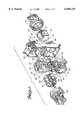
- FIG. 1is an isometric view illustrating the main components of the present embodiment rectangular connector consisting of the plug and receptacle shells, removable insert modules, bayonet coupling mechanism, backshell accessory, etc.
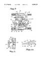
- FIG. 2Ais a side view of the removable insert module its main components consisting of: a rubber grommet depicting its environment resisting attributes, a rigid dielectric having user friendly contact retention clip, and a rubber insert having a dielectric (hard) face.
- the membersare bonded to form an assembly and a pressure ring provides enclosure to the assembly; and
- FIG. 2Bis a view of the side view of the removable insert module for the purpose of illustrating the keyway along the full length on the insert module;
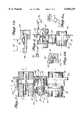
- FIG. 3is a section view on the present invention bayonet coupling mechanism illustrating the locking pin assembly on the plug shell (shaded area) is fully engaged with the helical socket on the receptacle shell (clear area);
- FIGS. 4A-4Fare detailed views of the locking pin assembly on the plug shell and the helical socket on the receptacle shell, depicting its component functionality.
- FIG. 5Ais a side view of the plug and receptacle connectors illustrating assembly on the present embodiment invention for the purpose of defining critical components configuration and its relationship to achieve connector functionality. Three views are included and discussed below.
- FIG. 5Bshows initial engagement between the plug and receptacle connectors focusing on the "pull-up" distance towards full coupling on the connectors.
- FIG. 5Cshows engagement as in the case of the prior art on the polarization device upon initial coupling of the plug and receptacle connectors.
- FIG. 5Dshows configured construction of the bayonet coupling mechanism having double right hand lead thread (ramp groove) illustrating on the coupling load, ramp angle and pull-up distance.
- FIG. 6is a side view of a fully coupled plug and receptacle connectors depicting full engagement on the pin and socket electrical contact and polarizing keys and keyways. Also, shown in FIGS. 6A-6B is the dimensional relationship between the detent hole and the double right hand lead thread for the purpose of establishing true position on the (bayonet) dowel pin relative to the ramp detent hole.
- a connector of this typecomprises a plug 38 and a receptacle shell 39 having removable insert modules 40 and a bayonet coupling mechanism (no identification given as it consists of several working components which will later be described in detail).
- An EMI spring 53(as in the prior art) and an O-ring seal 56, respectively, are provided in a groove around each insert housing on the plug shell 38 to ensure electrical grounding and environmental sealing to the mating receptacle shell 39.
- the insert module 40is an assembly containing a rubber grommet 2, a rigid dielectric contact retainer 3, a rubber insert 4 and a metal pressure ring 54.
- FIGS. 2A and 2BThese members are all fixedly configured as shown in FIGS. 2A and 2B such that the rubber grommet 2 is bonded onto the rigid dielectric contact retainer 3 which is bonded onto the rubber insert 4 and a pressure ring 54 provides enclosure to the bonded rubber grommet 2 and the rigid dielectric contact retainer 3.
- a detailed description of components described and shown in FIGS. 1-5 from my copending U.S. application Ser. No. 08/986,378, relating to the improved environment resistant seal webbing 5, a dielectric hard socket face insert 14, and the user friendly contact retention clips 20are properties also built onto the present invention rectangular connectors.
- FIG. 1is an isometric view on the present invention highlighting all the components. Although the functionality of its components are not readily apparent at this stage of the description, it can be pointed out that the integral bayonet coupling mechanism on the plug 38 and receptacle 39 shell far exceed in assembly and performance prior art external coupling mechanisms such as hold down clamp or track mounting or bulky jackscrew/jackpost types.
- FIGS. 3-6describe in detail the working mechanism on the present invention bayonet coupling rectangular connectors. Also, included are two polarizing keys 44 and keyways 45 which are similar to prior art. For clarity purposes, FIG. 3 is shown whereby the bayonet coupling components on the plug shell 38 are shaded in contrast to the clear illustration on the components of the receptacle shell 39. FIGS. 4A through 4F further accentuate this illustration. As shown in FIGS. 4A through 4C, the locking pin assembly is installed onto the plug shell 38 and can be described as follows:
- FIGS. 4D through 4Fit shows configuration and/or construction of the helical socket 42 built with an internal double right hand lead thread (ramp groove) 57 and is installed onto receptacle shell 39.
- the opening 62will accept the dowel pin 43 (shown on FIG. 4C) when the plug 38 connector starts to engage the receptacle 39 connector.
- the plug shell 38 movement towards the receptacle shellwill cause the dowel pin 43 to bottom against the helical ramp groove 57 thereby prohibiting any further advancement. This condition will enable the assembler to realize the coupling action between the plug 38 and receptacle 39 connectors shall be completed with a half turn on the locking pin 41.
- FIGS. 5A and 5Crespectively, that for this illustration, but not limited to, a ninety-thousands of an inch 67 gap or non-engagement between the electrical pin 6 and socket 15 contacts and a tenth-thousands of an inch 66 engagement on the polarizing keys 44 and keyways 45 exist.
- This arrangementis necessary for two reasons: a) the initial coupling forces between the plug 38 and receptacle 39 connectors will be at its minimum thereby lessening the potential of misalignment, and b) ensure proper grounding between the plug 38 and receptacle 39 connectors.
- the described conditionis all realized by virtue of positioning the dowel pin 43 at the start of the helical ramp grooves 57 during initial engagement or coupling on the plug 38 and receptacle 39 connectors. It is then by turning the hex head of the locking pin 41 that it will cause the dowel pin 43 to traverse the approximately twenty degree 65 ramp pulling in seventy pounds 64 of engagement force for a final coupling distance of three hundred forty thousands of an inch 63 as shown in FIG. 5D. As can be seen on FIGS. 6A-6B, the coupling action described moved the dowel pin 43 to enter the detent hole 61 located on the closed ends of the helical ramp grooves 57.
- FIGS. 2A and 2BAnother feature of the invention is the removable insert module 40 as shown in FIGS. 2A and 2B.
- the insert module 40consisting of a rubber grommet 2 bonded onto a rigid dielectric contact retainer 3 which is bonded onto the rubber insert 4 have all of the components and attributes as described, detailed and shown in FIGS. 1-5 of my copending U.S. application Ser. No. 08/986,378, incorporated herein by reference.
- Additional components on the insert module 40are a pressure ring 54 which is fixedly retained the bonded rubber grommet 2 and rigid dielectric contact retainer 3 and an O-ring seal 55 that is positioned in a groove around the pressure ring 54 housing to provide environmental sealing on the insert module 40.
- a keyway 48is built onto the pressure ring 54 and rubber insert 4.
- the keyway 48is interengageable with a key 49 on the plug 38 and receptacle 39 connector shells for ease of assembly when loading insert module 40 into the insert module cavity 77 on the plug 38 and receptacle 39 connector shell.
- the backshell 73retains and maintains the insert module 40 in a bottoming position inside the insert module cavity 77.
- the insert module 40 configurationwhich can be signal, power, coaxial/twinaxial or combinations. This embodiment property provides wiring flexibility and lower assembly and maintenance cost on the ARINC type rectangular connectors installation.
Landscapes
- Details Of Connecting Devices For Male And Female Coupling (AREA)
- Connector Housings Or Holding Contact Members (AREA)
Abstract
Description
This application is a continuation of application Ser. No. 08/960,942, filed Oct. 30, 1997, now abandoned, which was a continuation-in-part of application Ser. No. 08/687,082, filed Jul. 23, 1996, now abandoned, which was a continuation-in-part of application Ser. No. 08/521,776, filed Aug. 31, 1995, now abandoned, which was a continuation-in-part of application Ser. No. 08/435,122 filed May 5, 1995, now abandoned.
For this illustration but not limited to, the present invention utilizes an ARINC type electrical rectangular connector having an improved environment resisting rubber grommet, a dielectric hard face socket insert, user friendly contact retention clips and a bayonet coupling mechanism using dowel pins and helical ramp grooves to maintain the connector halves in their coupled condition.
It is an object of the present invention to significantly improve and increase reliability on the environment resisting property of the ARINC (rack and panel) rectangular connector.
A further object of the invention is to ensure proper mating or coupling on the electrical pin and socket contacts when splayed or bent contacts are affected.
Another object of the invention is to eliminate manufacturers variation on the construction of the contact retention clips and institute ease of assembly or disassembly on the electrical contacts.
Yet another object of this invention is to significantly lower cost in the assembly of connectors and greatly solidify the interconnection between the plug and receptacle connectors, simply stated, a new integral bayonet coupling mechanism replaces presently used external track mounting or hold down or bulky jackscrew/jackpost coupling mechanisms.
A further object of this invention is the modular construction which allows flexibility to the desired contact density or arrangement such as signal or power or coaxial/twinaxial contact or combination and wiring separation. This configuration is also a space saver.
The present invention provides improved wire sealing webs, provision of a hard dielectric face socket insert to detect splayed or bent electrical contacts, user friendly retention clips which enhance insertion and removal of contacts resulting in elimination of damaged or push back retention clips and locking (dowel) pin in the plug shell designed to engage a double right hand lead thread (ramp groove) in the receptacle shell formed a bayonet coupling assembly on the plug and receptacle connectors. The present invention provides much latitude in the installation of the connectors by reason of the built-in bayonet coupling mechanism, thereby expanding the normal rack and panel installation to areas where circular connectors are now used. It can also be appreciated that once the plug and receptacle rectangular connectors are coupled that they would not become inadvertently uncoupled, yet the connector should permit ready uncoupling when it is desired to separate the plug and receptacle connectors. Consequently, it is within the scope of the present invention to provide a connector that will withstand a high degree of vibration, large shock forces, and appreciable temperature variation. Furthermore, the present invention rectangular connector having modular configuration on the insert module allows interchangeability of pin and socket insert modules on plug and receptacle connectors for rapid and easy assembly and maintenance. By reason of improved electrical characteristics, the mechanical construction is also improved.
FIG. 1 is an isometric view illustrating the main components of the present embodiment rectangular connector consisting of the plug and receptacle shells, removable insert modules, bayonet coupling mechanism, backshell accessory, etc.
FIG. 2A is a side view of the removable insert module its main components consisting of: a rubber grommet depicting its environment resisting attributes, a rigid dielectric having user friendly contact retention clip, and a rubber insert having a dielectric (hard) face. The members are bonded to form an assembly and a pressure ring provides enclosure to the assembly; and
FIG. 2B is a view of the side view of the removable insert module for the purpose of illustrating the keyway along the full length on the insert module;
FIG. 3 is a section view on the present invention bayonet coupling mechanism illustrating the locking pin assembly on the plug shell (shaded area) is fully engaged with the helical socket on the receptacle shell (clear area);
FIGS. 4A-4F are detailed views of the locking pin assembly on the plug shell and the helical socket on the receptacle shell, depicting its component functionality.
FIG. 5A is a side view of the plug and receptacle connectors illustrating assembly on the present embodiment invention for the purpose of defining critical components configuration and its relationship to achieve connector functionality. Three views are included and discussed below.
FIG. 5B shows initial engagement between the plug and receptacle connectors focusing on the "pull-up" distance towards full coupling on the connectors.
FIG. 5C shows engagement as in the case of the prior art on the polarization device upon initial coupling of the plug and receptacle connectors.
FIG. 5D shows configured construction of the bayonet coupling mechanism having double right hand lead thread (ramp groove) illustrating on the coupling load, ramp angle and pull-up distance.
FIG. 6 is a side view of a fully coupled plug and receptacle connectors depicting full engagement on the pin and socket electrical contact and polarizing keys and keyways. Also, shown in FIGS. 6A-6B is the dimensional relationship between the detent hole and the double right hand lead thread for the purpose of establishing true position on the (bayonet) dowel pin relative to the ramp detent hole.
An electrical, rectangular, modular, environment resisting, bayonet coupling connector which is detailed in its entirety from FIG. 1 through FIG. 6. A connector of this type comprises aplug 38 and areceptacle shell 39 havingremovable insert modules 40 and a bayonet coupling mechanism (no identification given as it consists of several working components which will later be described in detail). An EMI spring 53 (as in the prior art) and an O-ring seal 56, respectively, are provided in a groove around each insert housing on theplug shell 38 to ensure electrical grounding and environmental sealing to themating receptacle shell 39. Theinsert module 40 is an assembly containing arubber grommet 2, a rigid dielectric contact retainer 3, arubber insert 4 and ametal pressure ring 54. These members are all fixedly configured as shown in FIGS. 2A and 2B such that therubber grommet 2 is bonded onto the rigid dielectric contact retainer 3 which is bonded onto therubber insert 4 and apressure ring 54 provides enclosure to the bondedrubber grommet 2 and the rigid dielectric contact retainer 3. A detailed description of components described and shown in FIGS. 1-5 from my copending U.S. application Ser. No. 08/986,378, relating to the improved environment resistant seal webbing 5, a dielectric hardsocket face insert 14, and the user friendlycontact retention clips 20 are properties also built onto the present invention rectangular connectors.
FIG. 1 is an isometric view on the present invention highlighting all the components. Although the functionality of its components are not readily apparent at this stage of the description, it can be pointed out that the integral bayonet coupling mechanism on theplug 38 andreceptacle 39 shell far exceed in assembly and performance prior art external coupling mechanisms such as hold down clamp or track mounting or bulky jackscrew/jackpost types.
FIGS. 3-6 describe in detail the working mechanism on the present invention bayonet coupling rectangular connectors. Also, included are two polarizingkeys 44 andkeyways 45 which are similar to prior art. For clarity purposes, FIG. 3 is shown whereby the bayonet coupling components on theplug shell 38 are shaded in contrast to the clear illustration on the components of thereceptacle shell 39. FIGS. 4A through 4F further accentuate this illustration. As shown in FIGS. 4A through 4C, the locking pin assembly is installed onto theplug shell 38 and can be described as follows:
a) Insertlocking pin 41 ontopositioning washer 46.
b) Installwavespring 52 onto lockingpin 41.
c) Assemblelocking pin 41 throughplug shell 38.
d) Installsnap ring 51 onto insertedlocking pin 41.
e) Insertcoil spring 50 onto lockingpin 41. Assemble one end ofcoil spring 50 intohole 74 onplug shell 38 and install other end ofcoil spring 50 ontohole 75 on lockingpin 41.
f) Wind half turn (clockwise) on lockingpin 41 to locate and installroll pin 47 ontoplug shell 38.
g) Assembledowel pin 43 onto lockingpin 41 usingdefinitive dimension 76. This assembly is critical to the functionality of the locking pin assembly.
Referring now to FIGS. 4D through 4F, it shows configuration and/or construction of thehelical socket 42 built with an internal double right hand lead thread (ramp groove) 57 and is installed ontoreceptacle shell 39. As can be seen and understood, theopening 62 will accept the dowel pin 43 (shown on FIG. 4C) when theplug 38 connector starts to engage thereceptacle 39 connector. Further, it will be appreciated that theplug shell 38 movement towards the receptacle shell will cause thedowel pin 43 to bottom against thehelical ramp groove 57 thereby prohibiting any further advancement. This condition will enable the assembler to realize the coupling action between theplug 38 andreceptacle 39 connectors shall be completed with a half turn on the lockingpin 41.
Describing now the bayonet coupling assembly between theplug 38 andreceptacle 39 connectors, it will be noted as shown on FIGS. 5A and 5C, respectively, that for this illustration, but not limited to, a ninety-thousands of aninch 67 gap or non-engagement between the electrical pin 6 andsocket 15 contacts and a tenth-thousands of aninch 66 engagement on thepolarizing keys 44 andkeyways 45 exist. This arrangement is necessary for two reasons: a) the initial coupling forces between theplug 38 andreceptacle 39 connectors will be at its minimum thereby lessening the potential of misalignment, and b) ensure proper grounding between theplug 38 andreceptacle 39 connectors. The described condition is all realized by virtue of positioning thedowel pin 43 at the start of thehelical ramp grooves 57 during initial engagement or coupling on theplug 38 andreceptacle 39 connectors. It is then by turning the hex head of the lockingpin 41 that it will cause thedowel pin 43 to traverse the approximately twentydegree 65 ramp pulling in seventypounds 64 of engagement force for a final coupling distance of three hundred forty thousands of aninch 63 as shown in FIG. 5D. As can be seen on FIGS. 6A-6B, the coupling action described moved thedowel pin 43 to enter thedetent hole 61 located on the closed ends of thehelical ramp grooves 57. Performing a very important role in maintaining thedowel pin 43 to be fully seated in thedetent hole 61 is awavespring 52 under compression due to its interfering relationship between the positioningwasher 46 and plug 38 connector shell. At this point, theplug 38 andreceptacle 39 connectors are fully coupled as evidenced by theelectrical engagement socket 15 contacts andpolarizing keys 44 andkeyways 45. Furthermore, it can be understood from FIG. 4B that theindicator arrowhead 58 on thepositioning washer 46 is pointing towards "HOME" 59. It is equally important to appreciate that the ten thousandth of aninch 71 engagement between thedowel pin 43 anddetent hole 61 allows minimal amount of effort in the uncoupling or disconnecting of theplug 38 from thereceptacle 39 connector.
When uncoupling or disconnecting theplug 38 andreceptacle 39 connectors, a reverse rotation on the hex head of the lockingpin 41 forces the partially receiveddowel pin 43 out of thedetent hole 61 causing theinterfacial seal compression 72 between themating insert modules 40 to be released thereby separating theplug 38 from thereceptacle 39 connector. It will also be recognized that the separation described will cause thesnap ring 51 to collide against theplug 38 connector wall which will add to the separation forces during the uncoupling of the connectors.
Another feature of the invention is theremovable insert module 40 as shown in FIGS. 2A and 2B. As described earlier, theinsert module 40 consisting of arubber grommet 2 bonded onto a rigid dielectric contact retainer 3 which is bonded onto therubber insert 4 have all of the components and attributes as described, detailed and shown in FIGS. 1-5 of my copending U.S. application Ser. No. 08/986,378, incorporated herein by reference. Additional components on theinsert module 40 are apressure ring 54 which is fixedly retained the bondedrubber grommet 2 and rigid dielectric contact retainer 3 and an O-ring seal 55 that is positioned in a groove around thepressure ring 54 housing to provide environmental sealing on theinsert module 40. Akeyway 48 is built onto thepressure ring 54 andrubber insert 4. Thekeyway 48 is interengageable with a key 49 on theplug 38 andreceptacle 39 connector shells for ease of assembly when loadinginsert module 40 into theinsert module cavity 77 on theplug 38 andreceptacle 39 connector shell. Thebackshell 73 retains and maintains theinsert module 40 in a bottoming position inside theinsert module cavity 77. Performing a very important role in the practicing of this invention is theinsert module 40 configuration which can be signal, power, coaxial/twinaxial or combinations. This embodiment property provides wiring flexibility and lower assembly and maintenance cost on the ARINC type rectangular connectors installation.
Claims (18)
1. An electrical rectangular connector comprising first and second components, each having interengageable contact means, coupling means for advancing said first component with respect to said second component to abut a portion of said second component and to cause engagement of said contact means;
means associated with said first and second components adapted for cooperation in connection with an insert module;
a locking pin assembly interposed between a portion of said coupling means and another portion of said first component which said locking pin assembly means advances to cause engagement on said second component;
a helical socket assembly interposed between a portion of said coupling means and another portion of said second component which said helical socket assembly means engages said first component.
2. The electrical connector defined in claim 1, further including an alignment key disposed at the rear end of an insert module cavity of said first and second component formed thereon projecting radially into a longitudinally directed keyway formed in the exterior of said insert module cavity thereby allowing for their axial engagement and disengagement while preventing their rotation relative to each other.
3. The electrical connector of claim 1, including a deformable O-ring seal positioned around said insert module thereby producing a fluid tight environment on assembly to the cavity of said insert module.
4. The electrical connector of claim 1 wherein said coupling means is rotatable to advance said first component with respect to said second component, said first component including a locking pin rotatable with said coupling means and having an axially directed dowel pin therein shiftable into a detent hole of said helical socket mounted on said second component when said first and second components are fully coupled together.
5. The electrical connector of claim 4 wherein said portion of said coupling means includes a snap ring and coil spring rotatable with both said coupling means and said locking pin, a positioning washer rotatable with said locking pin, and a deformable wavespring engageable by said positioning washer to cause deflection of said wavespring thereby producing a coupling of said first and second components.
6. The electrical connector of claim 4 wherein said positioning washer includes a visual indicator arrowhead designating full coupling on said first and second components.
7. The electrical connector of claim 4 wherein said portion of said coupling means includes said helical socket having internal double right hand lead thread or ramp grooves with said detent hole located at the closed end of said ramp groove receiving said dowel pin so as to provide a bayonet coupling means.
8. The electrical connectors of claim 4 wherein said dowel pin is directly positioned on the open end of said helical ramp groove, and, advancement of said first component onto second component is limited as said dowel pin bottoms against a portion of said helical ramp groove causing said locking pin to complete full coupling on said first and second components.
9. The electrical connector of claim 4 wherein said first and second components each have interengageable contact means; coupling means for advancing said first component with respect to said second component thereby causing a portion of said first components to abut a portion of said second component and to cause engagement of said respective contact means.
10. The electrical connector of claim 4 wherein a deformable O-ring seal mounted around said insert module of said first component produces a fluid tight environment on assembly to said second component.
11. An electrical rectangular connector comprising first and second components, each having interengageable contact means; coupling means for advancing said first component to abut a portion of said second component and to cause engagement of said respective interchangeable contact means and, wavespring means interposed between a portion of said coupling means and another portion of said first component which wavespring means is deflected by a decrease in the distance between said portions and said first mentioned portions abuting each other and wherein, said wavespring means is preloaded.
12. The electrical rectangular connector defined in claim 11 including detent means for assisting said wavespring in the retention of said components in their coupled relationship.
13. The electrical connector defined in claim 12 wherein said detent means includes a dowel pin shiftable into a retentive position.
14. A bayonet coupling connector comprising in combination:
a plug shell (38);
a receptacle shell (39) having removable insert modules (40) and a bayonet coupling mechanism;
a spring (53) and an O-ring seal (56) disposed in a groove around each insert housing on plug shell (38) thereby providing electronic grounding and environmental sealing to mating receptacle shell (39);
and wherein said insert module (40) comprises an assembly including a rubber grommet (2), a rigid dielectric contact retainer (3), a rubber insert (4), and a metal pressure ring (54);
said rubber grommet (2) bonded onto said rigid dielectric contact retainer (3), said dielectric contact retainer (3) bonded onto said rubber insert (4), and said metal pressure ring (54) providing enclosure of said bonded rubber grommet (2) and said rigid dielectric contact retainer ring (3).
15. The method of installing a locking pin assembly onto a plug shell (39) comprising the steps of:
inserting a locking pin (42) onto a positioning washer (4b);
installing a wavespring (52) onto the locking pin (41);
assembling the locking pin (41) through plug shell (38);
inserting a snap ring (51) onto inserted locking pin (41);
inserting a coil spring (50) onto locking pin (41);
assembling one end of coil spring (50) into a hole (74) on plug shell (38) and installing a further end of coil spring (50) into a hole (75) on locking pin (41);
winding a half turn in the clockwise direction on locking pin (41) to locate and install a roll pin (47) onto plug shell (38); and then,
assembling a dowel pin (43) onto locking pin (41) utilizing a definitive dimension (76).
16. In the method of installing a helical rocket (42) having a ramp groove (57) onto a receptacle shell (39):
causing a plug shell (38) to engage the receptacle shell (39) thereby causing an opening (62) to accept a dowel pin (43) when plug shell (38) begins to engage receptacle shell (39), and further causing the dowel pin (43) to bottom against the helical ramp groove (57) thereby preventing further advancement; and,
wherein coupling action between plug shell (38) and receptacle shell (39) is completed with a half turn on locking pin (41).
17. In the method of uncoupling plug shell (38) and receptacle shell (39):
providing reverse rotation on the hex head of a locking pin (41) thereby forcing a partially received dowel pin (43) out of a detent hole (61) causing interfacial seal compression (72) between the mating insert modules (40) to be released thereby separating plug shell (38) from receptacle shell (39) further causing a snap ring (51) to impact against the plug shell (38) wall causing added separation forces during uncoupling of connectors.
18. An insert module (40) comprising in combination:
a rubber grommet (2) bonded onto a rigid dielectric contact retainer (3), said rigid dielectric contact retainer (3) bonded onto a rubber insert (4);
said insert module (40 further including a pressure ring (54) and an O-ring seal (55) disposed in a groove around the pressure ring (54) housing thereby providing environmental sealing on said insert module (40);
a keyway (48) disposed on said pressure ring (54) and a rubber insert (4);
said keyway (48) interengageable with a key (49) on a plug (38) and receptacle (39) connector shells facilitating assembly when loading said insert module (40) into an insert module cavity (77) on said plug (38) and said receptacle connector (39); and,
a backshell (73) for retaining and maintaining said insert module (40) in a bottoming position inside said insert module cavity (77).
Priority Applications (1)
| Application Number | Priority Date | Filing Date | Title |
|---|---|---|---|
| US09/363,199US6048229A (en) | 1995-05-05 | 1999-07-29 | Environmentally resistant EMI rectangular connector having modular and bayonet coupling property |
Applications Claiming Priority (5)
| Application Number | Priority Date | Filing Date | Title |
|---|---|---|---|
| US43512295A | 1995-05-05 | 1995-05-05 | |
| US52177695A | 1995-08-31 | 1995-08-31 | |
| US68708296A | 1996-07-23 | 1996-07-23 | |
| US96094297A | 1997-10-30 | 1997-10-30 | |
| US09/363,199US6048229A (en) | 1995-05-05 | 1999-07-29 | Environmentally resistant EMI rectangular connector having modular and bayonet coupling property |
Related Parent Applications (1)
| Application Number | Title | Priority Date | Filing Date |
|---|---|---|---|
| US96094297AContinuation | 1995-05-05 | 1997-10-30 |
Publications (1)
| Publication Number | Publication Date |
|---|---|
| US6048229Atrue US6048229A (en) | 2000-04-11 |
Family
ID=27503840
Family Applications (1)
| Application Number | Title | Priority Date | Filing Date |
|---|---|---|---|
| US09/363,199Expired - LifetimeUS6048229A (en) | 1995-05-05 | 1999-07-29 | Environmentally resistant EMI rectangular connector having modular and bayonet coupling property |
Country Status (1)
| Country | Link |
|---|---|
| US (1) | US6048229A (en) |
Cited By (65)
| Publication number | Priority date | Publication date | Assignee | Title |
|---|---|---|---|---|
| US20010030189A1 (en)* | 2000-03-31 | 2001-10-18 | Hagerman Edwin Arthur | Housing for intrinsically-safe electronics |
| US6383031B1 (en)* | 2000-03-31 | 2002-05-07 | Tektronix, Inc. | Keyed electronic interconnect device for high speed signal and data transmission |
| US6537105B2 (en)* | 2000-03-15 | 2003-03-25 | The Furukawa Electric Co., Ltd. | Electrical connection box |
| US20070026705A1 (en)* | 2005-07-28 | 2007-02-01 | Fci Americas Technology, Inc. | Electrical connector assembly with connection assist |
| US20070099461A1 (en)* | 2005-10-06 | 2007-05-03 | Fci Americas Technology, Inc. | Electrical connector |
| US20080132098A1 (en)* | 2005-07-28 | 2008-06-05 | Fci Americas Technology, Inc. | Electrical connector assembly with connection assist |
| US8029315B2 (en) | 2009-04-01 | 2011-10-04 | John Mezzalingua Associates, Inc. | Coaxial cable connector with improved physical and RF sealing |
| US8075338B1 (en) | 2010-10-18 | 2011-12-13 | John Mezzalingua Associates, Inc. | Connector having a constant contact post |
| US8079860B1 (en) | 2010-07-22 | 2011-12-20 | John Mezzalingua Associates, Inc. | Cable connector having threaded locking collet and nut |
| US8113879B1 (en) | 2010-07-27 | 2012-02-14 | John Mezzalingua Associates, Inc. | One-piece compression connector body for coaxial cable connector |
| US8152551B2 (en) | 2010-07-22 | 2012-04-10 | John Mezzalingua Associates, Inc. | Port seizing cable connector nut and assembly |
| US8157589B2 (en) | 2004-11-24 | 2012-04-17 | John Mezzalingua Associates, Inc. | Connector having a conductively coated member and method of use thereof |
| US8167646B1 (en) | 2010-10-18 | 2012-05-01 | John Mezzalingua Associates, Inc. | Connector having electrical continuity about an inner dielectric and method of use thereof |
| US8167636B1 (en) | 2010-10-15 | 2012-05-01 | John Mezzalingua Associates, Inc. | Connector having a continuity member |
| US8167635B1 (en) | 2010-10-18 | 2012-05-01 | John Mezzalingua Associates, Inc. | Dielectric sealing member and method of use thereof |
| US8172612B2 (en) | 2005-01-25 | 2012-05-08 | Corning Gilbert Inc. | Electrical connector with grounding member |
| US8192237B2 (en) | 2009-05-22 | 2012-06-05 | John Mezzalingua Associates, Inc. | Coaxial cable connector having electrical continuity member |
| US8272893B2 (en) | 2009-11-16 | 2012-09-25 | Corning Gilbert Inc. | Integrally conductive and shielded coaxial cable connector |
| US8287310B2 (en) | 2009-02-24 | 2012-10-16 | Corning Gilbert Inc. | Coaxial connector with dual-grip nut |
| US8313345B2 (en) | 2009-04-02 | 2012-11-20 | John Mezzalingua Associates, Inc. | Coaxial cable continuity connector |
| US8323053B2 (en) | 2010-10-18 | 2012-12-04 | John Mezzalingua Associates, Inc. | Connector having a constant contact nut |
| US8337229B2 (en) | 2010-11-11 | 2012-12-25 | John Mezzalingua Associates, Inc. | Connector having a nut-body continuity element and method of use thereof |
| US8342879B2 (en) | 2011-03-25 | 2013-01-01 | John Mezzalingua Associates, Inc. | Coaxial cable connector |
| US8348697B2 (en) | 2011-04-22 | 2013-01-08 | John Mezzalingua Associates, Inc. | Coaxial cable connector having slotted post member |
| US8366481B2 (en) | 2011-03-30 | 2013-02-05 | John Mezzalingua Associates, Inc. | Continuity maintaining biasing member |
| US8388377B2 (en) | 2011-04-01 | 2013-03-05 | John Mezzalingua Associates, Inc. | Slide actuated coaxial cable connector |
| US8398421B2 (en) | 2011-02-01 | 2013-03-19 | John Mezzalingua Associates, Inc. | Connector having a dielectric seal and method of use thereof |
| US8414322B2 (en) | 2010-12-14 | 2013-04-09 | Ppc Broadband, Inc. | Push-on CATV port terminator |
| US8444445B2 (en) | 2009-05-22 | 2013-05-21 | Ppc Broadband, Inc. | Coaxial cable connector having electrical continuity member |
| US8465322B2 (en) | 2011-03-25 | 2013-06-18 | Ppc Broadband, Inc. | Coaxial cable connector |
| US8469739B2 (en) | 2011-02-08 | 2013-06-25 | Belden Inc. | Cable connector with biasing element |
| US8506325B2 (en) | 2008-09-30 | 2013-08-13 | Belden Inc. | Cable connector having a biasing element |
| US8573996B2 (en) | 2009-05-22 | 2013-11-05 | Ppc Broadband, Inc. | Coaxial cable connector having electrical continuity member |
| US8591244B2 (en) | 2011-07-08 | 2013-11-26 | Ppc Broadband, Inc. | Cable connector |
| US8753147B2 (en) | 2011-06-10 | 2014-06-17 | Ppc Broadband, Inc. | Connector having a coupling member for locking onto a port and maintaining electrical continuity |
| US8888526B2 (en) | 2010-08-10 | 2014-11-18 | Corning Gilbert, Inc. | Coaxial cable connector with radio frequency interference and grounding shield |
| US9017101B2 (en) | 2011-03-30 | 2015-04-28 | Ppc Broadband, Inc. | Continuity maintaining biasing member |
| US9048599B2 (en) | 2013-10-28 | 2015-06-02 | Corning Gilbert Inc. | Coaxial cable connector having a gripping member with a notch and disposed inside a shell |
| US9071019B2 (en) | 2010-10-27 | 2015-06-30 | Corning Gilbert, Inc. | Push-on cable connector with a coupler and retention and release mechanism |
| US9130281B2 (en) | 2013-04-17 | 2015-09-08 | Ppc Broadband, Inc. | Post assembly for coaxial cable connectors |
| US9136654B2 (en) | 2012-01-05 | 2015-09-15 | Corning Gilbert, Inc. | Quick mount connector for a coaxial cable |
| US9147963B2 (en) | 2012-11-29 | 2015-09-29 | Corning Gilbert Inc. | Hardline coaxial connector with a locking ferrule |
| US9147955B2 (en) | 2011-11-02 | 2015-09-29 | Ppc Broadband, Inc. | Continuity providing port |
| US9153911B2 (en) | 2013-02-19 | 2015-10-06 | Corning Gilbert Inc. | Coaxial cable continuity connector |
| US9166348B2 (en) | 2010-04-13 | 2015-10-20 | Corning Gilbert Inc. | Coaxial connector with inhibited ingress and improved grounding |
| US9172154B2 (en) | 2013-03-15 | 2015-10-27 | Corning Gilbert Inc. | Coaxial cable connector with integral RFI protection |
| US9190744B2 (en) | 2011-09-14 | 2015-11-17 | Corning Optical Communications Rf Llc | Coaxial cable connector with radio frequency interference and grounding shield |
| US9203167B2 (en) | 2011-05-26 | 2015-12-01 | Ppc Broadband, Inc. | Coaxial cable connector with conductive seal |
| US9287659B2 (en) | 2012-10-16 | 2016-03-15 | Corning Optical Communications Rf Llc | Coaxial cable connector with integral RFI protection |
| US9407016B2 (en) | 2012-02-22 | 2016-08-02 | Corning Optical Communications Rf Llc | Coaxial cable connector with integral continuity contacting portion |
| US9525220B1 (en) | 2015-11-25 | 2016-12-20 | Corning Optical Communications LLC | Coaxial cable connector |
| US9548557B2 (en) | 2013-06-26 | 2017-01-17 | Corning Optical Communications LLC | Connector assemblies and methods of manufacture |
| US9548572B2 (en) | 2014-11-03 | 2017-01-17 | Corning Optical Communications LLC | Coaxial cable connector having a coupler and a post with a contacting portion and a shoulder |
| US9570845B2 (en) | 2009-05-22 | 2017-02-14 | Ppc Broadband, Inc. | Connector having a continuity member operable in a radial direction |
| US9590287B2 (en) | 2015-02-20 | 2017-03-07 | Corning Optical Communications Rf Llc | Surge protected coaxial termination |
| US9711917B2 (en) | 2011-05-26 | 2017-07-18 | Ppc Broadband, Inc. | Band spring continuity member for coaxial cable connector |
| US9762008B2 (en) | 2013-05-20 | 2017-09-12 | Corning Optical Communications Rf Llc | Coaxial cable connector with integral RFI protection |
| US9859631B2 (en) | 2011-09-15 | 2018-01-02 | Corning Optical Communications Rf Llc | Coaxial cable connector with integral radio frequency interference and grounding shield |
| US10033122B2 (en) | 2015-02-20 | 2018-07-24 | Corning Optical Communications Rf Llc | Cable or conduit connector with jacket retention feature |
| US10211547B2 (en) | 2015-09-03 | 2019-02-19 | Corning Optical Communications Rf Llc | Coaxial cable connector |
| CN109546437A (en)* | 2018-12-29 | 2019-03-29 | 镇江奥博通信设备有限公司 | A kind of rectangular seal low-frequency electric connector |
| US10290958B2 (en) | 2013-04-29 | 2019-05-14 | Corning Optical Communications Rf Llc | Coaxial cable connector with integral RFI protection and biasing ring |
| CN112566402A (en)* | 2020-11-05 | 2021-03-26 | 中国船舶重工集团公司第七0九研究所 | Connecting method convenient for quick disassembly and assembly of reinforcing module of control table board |
| US11128086B2 (en) | 2018-05-11 | 2021-09-21 | The Boeing Company | Apparatus for contact insertion and retention testing |
| US12034264B2 (en) | 2021-03-31 | 2024-07-09 | Corning Optical Communications Rf Llc | Coaxial cable connector assemblies with outer conductor engagement features and methods for using the same |
Citations (10)
| Publication number | Priority date | Publication date | Assignee | Title |
|---|---|---|---|---|
| US3477061A (en)* | 1966-06-20 | 1969-11-04 | Bunker Ramo | Contact retention device |
| US3550065A (en)* | 1968-01-11 | 1970-12-22 | G & H Technology | Electrical connector |
| US4229064A (en)* | 1978-10-25 | 1980-10-21 | Trw Inc. | Polarizing adapter sleeves for electrical connectors |
| US4736999A (en)* | 1987-03-25 | 1988-04-12 | Hubbell Incorporated | Electrical connector with component keying system |
| US4820204A (en)* | 1986-12-12 | 1989-04-11 | Amp Incorporated | Modular electrical connector assembly |
| US4938718A (en)* | 1981-02-18 | 1990-07-03 | Amp Incorporated | Cylindrical connector keying means |
| US5211582A (en)* | 1992-03-09 | 1993-05-18 | Amphenol Corporation | Repairable connector |
| US5219296A (en)* | 1992-01-08 | 1993-06-15 | Amp Incorporated | Modular connector assembly and method of assembling same |
| US5558533A (en)* | 1992-12-18 | 1996-09-24 | Yazaki Corporation | Electrical connector |
| US5647766A (en)* | 1995-05-26 | 1997-07-15 | The Whitaker Corporation | Modular connector assembly having removable contacts |
- 1999
- 1999-07-29USUS09/363,199patent/US6048229A/ennot_activeExpired - Lifetime
Patent Citations (10)
| Publication number | Priority date | Publication date | Assignee | Title |
|---|---|---|---|---|
| US3477061A (en)* | 1966-06-20 | 1969-11-04 | Bunker Ramo | Contact retention device |
| US3550065A (en)* | 1968-01-11 | 1970-12-22 | G & H Technology | Electrical connector |
| US4229064A (en)* | 1978-10-25 | 1980-10-21 | Trw Inc. | Polarizing adapter sleeves for electrical connectors |
| US4938718A (en)* | 1981-02-18 | 1990-07-03 | Amp Incorporated | Cylindrical connector keying means |
| US4820204A (en)* | 1986-12-12 | 1989-04-11 | Amp Incorporated | Modular electrical connector assembly |
| US4736999A (en)* | 1987-03-25 | 1988-04-12 | Hubbell Incorporated | Electrical connector with component keying system |
| US5219296A (en)* | 1992-01-08 | 1993-06-15 | Amp Incorporated | Modular connector assembly and method of assembling same |
| US5211582A (en)* | 1992-03-09 | 1993-05-18 | Amphenol Corporation | Repairable connector |
| US5558533A (en)* | 1992-12-18 | 1996-09-24 | Yazaki Corporation | Electrical connector |
| US5647766A (en)* | 1995-05-26 | 1997-07-15 | The Whitaker Corporation | Modular connector assembly having removable contacts |
Cited By (138)
| Publication number | Priority date | Publication date | Assignee | Title |
|---|---|---|---|---|
| US6537105B2 (en)* | 2000-03-15 | 2003-03-25 | The Furukawa Electric Co., Ltd. | Electrical connection box |
| US20010030189A1 (en)* | 2000-03-31 | 2001-10-18 | Hagerman Edwin Arthur | Housing for intrinsically-safe electronics |
| US6383031B1 (en)* | 2000-03-31 | 2002-05-07 | Tektronix, Inc. | Keyed electronic interconnect device for high speed signal and data transmission |
| US6708834B2 (en) | 2000-03-31 | 2004-03-23 | Micro Motion, Inc. | Housing for intrinsically-safe electronics |
| US10965063B2 (en) | 2004-11-24 | 2021-03-30 | Ppc Broadband, Inc. | Connector having a grounding member |
| US10038284B2 (en) | 2004-11-24 | 2018-07-31 | Ppc Broadband, Inc. | Connector having a grounding member |
| US9312611B2 (en) | 2004-11-24 | 2016-04-12 | Ppc Broadband, Inc. | Connector having a conductively coated member and method of use thereof |
| US11984687B2 (en) | 2004-11-24 | 2024-05-14 | Ppc Broadband, Inc. | Connector having a grounding member |
| US12009619B2 (en) | 2004-11-24 | 2024-06-11 | Ppc Broadband, Inc. | Connector having a connector body conductive member |
| US10446983B2 (en) | 2004-11-24 | 2019-10-15 | Ppc Broadband, Inc. | Connector having a grounding member |
| US8157589B2 (en) | 2004-11-24 | 2012-04-17 | John Mezzalingua Associates, Inc. | Connector having a conductively coated member and method of use thereof |
| US10756455B2 (en) | 2005-01-25 | 2020-08-25 | Corning Optical Communications Rf Llc | Electrical connector with grounding member |
| US8172612B2 (en) | 2005-01-25 | 2012-05-08 | Corning Gilbert Inc. | Electrical connector with grounding member |
| US8690603B2 (en) | 2005-01-25 | 2014-04-08 | Corning Gilbert Inc. | Electrical connector with grounding member |
| US7462047B2 (en) | 2005-07-28 | 2008-12-09 | Fci Americas Technology, Inc. | Electrical connector assembly with connection assist |
| US20080132098A1 (en)* | 2005-07-28 | 2008-06-05 | Fci Americas Technology, Inc. | Electrical connector assembly with connection assist |
| US7744390B2 (en) | 2005-07-28 | 2010-06-29 | Fci Americas Technology, Inc. | Electrical connector assembly with connection assist |
| US20100227494A1 (en)* | 2005-07-28 | 2010-09-09 | Fci Americas Technology, Llc | Electrical connector assembly with connection assist |
| US20070224862A1 (en)* | 2005-07-28 | 2007-09-27 | Fci Americas Technology, Inc. | Electrical connector assembly with connection assist |
| US20070026705A1 (en)* | 2005-07-28 | 2007-02-01 | Fci Americas Technology, Inc. | Electrical connector assembly with connection assist |
| US8747130B2 (en) | 2005-07-28 | 2014-06-10 | Delphi International Operations Luxembourg S.A.R.L. | Electrical connector assembly with connection assist |
| US7241155B2 (en) | 2005-07-28 | 2007-07-10 | Fci Americas Technology, Inc. | Electrical connector assembly with connection assist |
| US7361036B2 (en) | 2005-10-06 | 2008-04-22 | Fci Americas Technology, Inc. | Electrical connector with lever and latch |
| US7695297B2 (en) | 2005-10-06 | 2010-04-13 | Fci Americas Technology, Inc. | Electrical connector with laterally moving terminal position assurance (TPA) member |
| US20090221167A1 (en)* | 2005-10-06 | 2009-09-03 | Fci Americas Technology, Inc. | Electrical connector |
| US7559778B2 (en) | 2005-10-06 | 2009-07-14 | Fci Americas Technology, Inc. | Electrical connector |
| US20080166903A1 (en)* | 2005-10-06 | 2008-07-10 | Fci Americas Technology, Inc. | Electrical Connector |
| US20070099461A1 (en)* | 2005-10-06 | 2007-05-03 | Fci Americas Technology, Inc. | Electrical connector |
| US8506325B2 (en) | 2008-09-30 | 2013-08-13 | Belden Inc. | Cable connector having a biasing element |
| US8287310B2 (en) | 2009-02-24 | 2012-10-16 | Corning Gilbert Inc. | Coaxial connector with dual-grip nut |
| US8029315B2 (en) | 2009-04-01 | 2011-10-04 | John Mezzalingua Associates, Inc. | Coaxial cable connector with improved physical and RF sealing |
| US8506326B2 (en) | 2009-04-02 | 2013-08-13 | Ppc Broadband, Inc. | Coaxial cable continuity connector |
| US8313345B2 (en) | 2009-04-02 | 2012-11-20 | John Mezzalingua Associates, Inc. | Coaxial cable continuity connector |
| US8313353B2 (en) | 2009-05-22 | 2012-11-20 | John Mezzalingua Associates, Inc. | Coaxial cable connector having electrical continuity member |
| US9660398B2 (en) | 2009-05-22 | 2017-05-23 | Ppc Broadband, Inc. | Coaxial cable connector having electrical continuity member |
| US12244108B2 (en) | 2009-05-22 | 2025-03-04 | Ppc Broadband, Inc. | Ground portion for maintaining a ground path in a coaxial cable connector |
| US8323060B2 (en) | 2009-05-22 | 2012-12-04 | John Mezzalingua Associates, Inc. | Coaxial cable connector having electrical continuity member |
| US8801448B2 (en) | 2009-05-22 | 2014-08-12 | Ppc Broadband, Inc. | Coaxial cable connector having electrical continuity structure |
| US8287320B2 (en) | 2009-05-22 | 2012-10-16 | John Mezzalingua Associates, Inc. | Coaxial cable connector having electrical continuity member |
| US8647136B2 (en) | 2009-05-22 | 2014-02-11 | Ppc Broadband, Inc. | Coaxial cable connector having electrical continuity member |
| US10931068B2 (en) | 2009-05-22 | 2021-02-23 | Ppc Broadband, Inc. | Connector having a grounding member operable in a radial direction |
| US10862251B2 (en) | 2009-05-22 | 2020-12-08 | Ppc Broadband, Inc. | Coaxial cable connector having an electrical grounding portion |
| US8597041B2 (en) | 2009-05-22 | 2013-12-03 | Ppc Broadband, Inc. | Coaxial cable connector having electrical continuity member |
| US8444445B2 (en) | 2009-05-22 | 2013-05-21 | Ppc Broadband, Inc. | Coaxial cable connector having electrical continuity member |
| US8192237B2 (en) | 2009-05-22 | 2012-06-05 | John Mezzalingua Associates, Inc. | Coaxial cable connector having electrical continuity member |
| US8573996B2 (en) | 2009-05-22 | 2013-11-05 | Ppc Broadband, Inc. | Coaxial cable connector having electrical continuity member |
| US8562366B2 (en) | 2009-05-22 | 2013-10-22 | Ppc Broadband, Inc. | Coaxial cable connector having electrical continuity member |
| US9419389B2 (en) | 2009-05-22 | 2016-08-16 | Ppc Broadband, Inc. | Coaxial cable connector having electrical continuity member |
| US9496661B2 (en) | 2009-05-22 | 2016-11-15 | Ppc Broadband, Inc. | Coaxial cable connector having electrical continuity member |
| US9570845B2 (en) | 2009-05-22 | 2017-02-14 | Ppc Broadband, Inc. | Connector having a continuity member operable in a radial direction |
| US8272893B2 (en) | 2009-11-16 | 2012-09-25 | Corning Gilbert Inc. | Integrally conductive and shielded coaxial cable connector |
| US10312629B2 (en) | 2010-04-13 | 2019-06-04 | Corning Optical Communications Rf Llc | Coaxial connector with inhibited ingress and improved grounding |
| US9905959B2 (en) | 2010-04-13 | 2018-02-27 | Corning Optical Communication RF LLC | Coaxial connector with inhibited ingress and improved grounding |
| US9166348B2 (en) | 2010-04-13 | 2015-10-20 | Corning Gilbert Inc. | Coaxial connector with inhibited ingress and improved grounding |
| US8152551B2 (en) | 2010-07-22 | 2012-04-10 | John Mezzalingua Associates, Inc. | Port seizing cable connector nut and assembly |
| US8079860B1 (en) | 2010-07-22 | 2011-12-20 | John Mezzalingua Associates, Inc. | Cable connector having threaded locking collet and nut |
| US8113879B1 (en) | 2010-07-27 | 2012-02-14 | John Mezzalingua Associates, Inc. | One-piece compression connector body for coaxial cable connector |
| US8888526B2 (en) | 2010-08-10 | 2014-11-18 | Corning Gilbert, Inc. | Coaxial cable connector with radio frequency interference and grounding shield |
| US8167636B1 (en) | 2010-10-15 | 2012-05-01 | John Mezzalingua Associates, Inc. | Connector having a continuity member |
| US8382517B2 (en) | 2010-10-18 | 2013-02-26 | John Mezzalingua Associates, Inc. | Dielectric sealing member and method of use thereof |
| US8167646B1 (en) | 2010-10-18 | 2012-05-01 | John Mezzalingua Associates, Inc. | Connector having electrical continuity about an inner dielectric and method of use thereof |
| US8323053B2 (en) | 2010-10-18 | 2012-12-04 | John Mezzalingua Associates, Inc. | Connector having a constant contact nut |
| US8075338B1 (en) | 2010-10-18 | 2011-12-13 | John Mezzalingua Associates, Inc. | Connector having a constant contact post |
| US8167635B1 (en) | 2010-10-18 | 2012-05-01 | John Mezzalingua Associates, Inc. | Dielectric sealing member and method of use thereof |
| US9071019B2 (en) | 2010-10-27 | 2015-06-30 | Corning Gilbert, Inc. | Push-on cable connector with a coupler and retention and release mechanism |
| US8920182B2 (en) | 2010-11-11 | 2014-12-30 | Ppc Broadband, Inc. | Connector having a coupler-body continuity member |
| US10686264B2 (en) | 2010-11-11 | 2020-06-16 | Ppc Broadband, Inc. | Coaxial cable connector having a grounding bridge portion |
| US8915754B2 (en) | 2010-11-11 | 2014-12-23 | Ppc Broadband, Inc. | Connector having a coupler-body continuity member |
| US8529279B2 (en) | 2010-11-11 | 2013-09-10 | Ppc Broadband, Inc. | Connector having a nut-body continuity element and method of use thereof |
| US8920192B2 (en) | 2010-11-11 | 2014-12-30 | Ppc Broadband, Inc. | Connector having a coupler-body continuity member |
| US8858251B2 (en) | 2010-11-11 | 2014-10-14 | Ppc Broadband, Inc. | Connector having a coupler-body continuity member |
| US8337229B2 (en) | 2010-11-11 | 2012-12-25 | John Mezzalingua Associates, Inc. | Connector having a nut-body continuity element and method of use thereof |
| US8550835B2 (en) | 2010-11-11 | 2013-10-08 | Ppc Broadband, Inc. | Connector having a nut-body continuity element and method of use thereof |
| US8414322B2 (en) | 2010-12-14 | 2013-04-09 | Ppc Broadband, Inc. | Push-on CATV port terminator |
| US8398421B2 (en) | 2011-02-01 | 2013-03-19 | John Mezzalingua Associates, Inc. | Connector having a dielectric seal and method of use thereof |
| US8469739B2 (en) | 2011-02-08 | 2013-06-25 | Belden Inc. | Cable connector with biasing element |
| US8342879B2 (en) | 2011-03-25 | 2013-01-01 | John Mezzalingua Associates, Inc. | Coaxial cable connector |
| US8465322B2 (en) | 2011-03-25 | 2013-06-18 | Ppc Broadband, Inc. | Coaxial cable connector |
| US9153917B2 (en) | 2011-03-25 | 2015-10-06 | Ppc Broadband, Inc. | Coaxial cable connector |
| US9608345B2 (en) | 2011-03-30 | 2017-03-28 | Ppc Broadband, Inc. | Continuity maintaining biasing member |
| US8485845B2 (en) | 2011-03-30 | 2013-07-16 | Ppc Broadband, Inc. | Continuity maintaining biasing member |
| US10186790B2 (en) | 2011-03-30 | 2019-01-22 | Ppc Broadband, Inc. | Connector producing a biasing force |
| US9660360B2 (en) | 2011-03-30 | 2017-05-23 | Ppc Broadband, Inc. | Connector producing a biasing force |
| US8366481B2 (en) | 2011-03-30 | 2013-02-05 | John Mezzalingua Associates, Inc. | Continuity maintaining biasing member |
| US8475205B2 (en) | 2011-03-30 | 2013-07-02 | Ppc Broadband, Inc. | Continuity maintaining biasing member |
| US8469740B2 (en) | 2011-03-30 | 2013-06-25 | Ppc Broadband, Inc. | Continuity maintaining biasing member |
| US9595776B2 (en) | 2011-03-30 | 2017-03-14 | Ppc Broadband, Inc. | Connector producing a biasing force |
| US9017101B2 (en) | 2011-03-30 | 2015-04-28 | Ppc Broadband, Inc. | Continuity maintaining biasing member |
| US8480431B2 (en) | 2011-03-30 | 2013-07-09 | Ppc Broadband, Inc. | Continuity maintaining biasing member |
| US11811184B2 (en) | 2011-03-30 | 2023-11-07 | Ppc Broadband, Inc. | Connector producing a biasing force |
| US10559898B2 (en) | 2011-03-30 | 2020-02-11 | Ppc Broadband, Inc. | Connector producing a biasing force |
| US8480430B2 (en) | 2011-03-30 | 2013-07-09 | Ppc Broadband, Inc. | Continuity maintaining biasing member |
| US8388377B2 (en) | 2011-04-01 | 2013-03-05 | John Mezzalingua Associates, Inc. | Slide actuated coaxial cable connector |
| US8348697B2 (en) | 2011-04-22 | 2013-01-08 | John Mezzalingua Associates, Inc. | Coaxial cable connector having slotted post member |
| US9711917B2 (en) | 2011-05-26 | 2017-07-18 | Ppc Broadband, Inc. | Band spring continuity member for coaxial cable connector |
| US10707629B2 (en) | 2011-05-26 | 2020-07-07 | Ppc Broadband, Inc. | Grounding member for coaxial cable connector |
| US11283226B2 (en) | 2011-05-26 | 2022-03-22 | Ppc Broadband, Inc. | Grounding member for coaxial cable connector |
| US9203167B2 (en) | 2011-05-26 | 2015-12-01 | Ppc Broadband, Inc. | Coaxial cable connector with conductive seal |
| US8753147B2 (en) | 2011-06-10 | 2014-06-17 | Ppc Broadband, Inc. | Connector having a coupling member for locking onto a port and maintaining electrical continuity |
| US8758050B2 (en) | 2011-06-10 | 2014-06-24 | Hiscock & Barclay LLP | Connector having a coupling member for locking onto a port and maintaining electrical continuity |
| US8591244B2 (en) | 2011-07-08 | 2013-11-26 | Ppc Broadband, Inc. | Cable connector |
| US9190744B2 (en) | 2011-09-14 | 2015-11-17 | Corning Optical Communications Rf Llc | Coaxial cable connector with radio frequency interference and grounding shield |
| US9859631B2 (en) | 2011-09-15 | 2018-01-02 | Corning Optical Communications Rf Llc | Coaxial cable connector with integral radio frequency interference and grounding shield |
| US10700475B2 (en) | 2011-11-02 | 2020-06-30 | Ppc Broadband, Inc. | Devices for biasingly maintaining a port ground path |
| US9537232B2 (en) | 2011-11-02 | 2017-01-03 | Ppc Broadband, Inc. | Continuity providing port |
| US11233362B2 (en) | 2011-11-02 | 2022-01-25 | Ppc Broadband, Inc. | Devices for biasingly maintaining a port ground path |
| US9147955B2 (en) | 2011-11-02 | 2015-09-29 | Ppc Broadband, Inc. | Continuity providing port |
| US10116099B2 (en) | 2011-11-02 | 2018-10-30 | Ppc Broadband, Inc. | Devices for biasingly maintaining a port ground path |
| US9768565B2 (en) | 2012-01-05 | 2017-09-19 | Corning Optical Communications Rf Llc | Quick mount connector for a coaxial cable |
| US9484645B2 (en) | 2012-01-05 | 2016-11-01 | Corning Optical Communications Rf Llc | Quick mount connector for a coaxial cable |
| US9136654B2 (en) | 2012-01-05 | 2015-09-15 | Corning Gilbert, Inc. | Quick mount connector for a coaxial cable |
| US9407016B2 (en) | 2012-02-22 | 2016-08-02 | Corning Optical Communications Rf Llc | Coaxial cable connector with integral continuity contacting portion |
| US9722363B2 (en) | 2012-10-16 | 2017-08-01 | Corning Optical Communications Rf Llc | Coaxial cable connector with integral RFI protection |
| US10236636B2 (en) | 2012-10-16 | 2019-03-19 | Corning Optical Communications Rf Llc | Coaxial cable connector with integral RFI protection |
| US9287659B2 (en) | 2012-10-16 | 2016-03-15 | Corning Optical Communications Rf Llc | Coaxial cable connector with integral RFI protection |
| US9912105B2 (en) | 2012-10-16 | 2018-03-06 | Corning Optical Communications Rf Llc | Coaxial cable connector with integral RFI protection |
| US9147963B2 (en) | 2012-11-29 | 2015-09-29 | Corning Gilbert Inc. | Hardline coaxial connector with a locking ferrule |
| US9153911B2 (en) | 2013-02-19 | 2015-10-06 | Corning Gilbert Inc. | Coaxial cable continuity connector |
| US9172154B2 (en) | 2013-03-15 | 2015-10-27 | Corning Gilbert Inc. | Coaxial cable connector with integral RFI protection |
| US9130281B2 (en) | 2013-04-17 | 2015-09-08 | Ppc Broadband, Inc. | Post assembly for coaxial cable connectors |
| US10290958B2 (en) | 2013-04-29 | 2019-05-14 | Corning Optical Communications Rf Llc | Coaxial cable connector with integral RFI protection and biasing ring |
| US10396508B2 (en) | 2013-05-20 | 2019-08-27 | Corning Optical Communications Rf Llc | Coaxial cable connector with integral RFI protection |
| US9762008B2 (en) | 2013-05-20 | 2017-09-12 | Corning Optical Communications Rf Llc | Coaxial cable connector with integral RFI protection |
| US9548557B2 (en) | 2013-06-26 | 2017-01-17 | Corning Optical Communications LLC | Connector assemblies and methods of manufacture |
| US9048599B2 (en) | 2013-10-28 | 2015-06-02 | Corning Gilbert Inc. | Coaxial cable connector having a gripping member with a notch and disposed inside a shell |
| US9548572B2 (en) | 2014-11-03 | 2017-01-17 | Corning Optical Communications LLC | Coaxial cable connector having a coupler and a post with a contacting portion and a shoulder |
| US9991651B2 (en) | 2014-11-03 | 2018-06-05 | Corning Optical Communications Rf Llc | Coaxial cable connector with post including radially expanding tabs |
| US9590287B2 (en) | 2015-02-20 | 2017-03-07 | Corning Optical Communications Rf Llc | Surge protected coaxial termination |
| US10033122B2 (en) | 2015-02-20 | 2018-07-24 | Corning Optical Communications Rf Llc | Cable or conduit connector with jacket retention feature |
| US10211547B2 (en) | 2015-09-03 | 2019-02-19 | Corning Optical Communications Rf Llc | Coaxial cable connector |
| US9882320B2 (en) | 2015-11-25 | 2018-01-30 | Corning Optical Communications Rf Llc | Coaxial cable connector |
| US9525220B1 (en) | 2015-11-25 | 2016-12-20 | Corning Optical Communications LLC | Coaxial cable connector |
| US11128086B2 (en) | 2018-05-11 | 2021-09-21 | The Boeing Company | Apparatus for contact insertion and retention testing |
| CN109546437B (en)* | 2018-12-29 | 2024-05-24 | 镇江奥博通信设备有限公司 | Rectangular sealing low-frequency electric connector |
| CN109546437A (en)* | 2018-12-29 | 2019-03-29 | 镇江奥博通信设备有限公司 | A kind of rectangular seal low-frequency electric connector |
| CN112566402B (en)* | 2020-11-05 | 2023-01-31 | 中国船舶重工集团公司第七0九研究所 | Connecting method convenient for quick disassembly and assembly of reinforcing module of control table board |
| CN112566402A (en)* | 2020-11-05 | 2021-03-26 | 中国船舶重工集团公司第七0九研究所 | Connecting method convenient for quick disassembly and assembly of reinforcing module of control table board |
| US12034264B2 (en) | 2021-03-31 | 2024-07-09 | Corning Optical Communications Rf Llc | Coaxial cable connector assemblies with outer conductor engagement features and methods for using the same |
Similar Documents
| Publication | Publication Date | Title |
|---|---|---|
| US6048229A (en) | Environmentally resistant EMI rectangular connector having modular and bayonet coupling property | |
| US5718596A (en) | Connector engaging structure | |
| US5775953A (en) | Low-insertion-force connector assembly | |
| EP0638965B1 (en) | Circular bulkhead connector assembly | |
| US4676575A (en) | Sealing member for bulkhead connector | |
| US6361348B1 (en) | Right angle, snap on coaxial electrical connector | |
| CN111641080B (en) | Spring plate locking type push-pull connector | |
| US5266047A (en) | Electrical connector assembly | |
| US4721478A (en) | Water sealed electrical connector | |
| US20020090856A1 (en) | Coax cable connector assembly with latching housing | |
| CA2308319C (en) | Wire harness connector | |
| EP0480337B1 (en) | Insert retention gas tight seal for an electrical connector and method of making same | |
| US6475039B1 (en) | Electrical connector contact pin | |
| JP2926676B2 (en) | Housing mating type connector | |
| EP0913888A2 (en) | High performance MIL-C-26500 and ARINC connectors | |
| US5551147A (en) | Tool for removing a repairable electrical connector insert | |
| US5791932A (en) | Releasable connector assembly | |
| US6179641B1 (en) | Electrical connector | |
| US5569041A (en) | Low insertion force electrical connector | |
| EP1006380B1 (en) | Electrical and/or optical connector | |
| US5626493A (en) | Through-wall electrical connector | |
| US6010352A (en) | Connector | |
| CN118487078A (en) | Push-pull connector with self-locking protection | |
| JPH0719186Y2 (en) | Storage unit device for printed circuit boards | |
| US20200119482A1 (en) | Connector |
Legal Events
| Date | Code | Title | Description |
|---|---|---|---|
| STCF | Information on status: patent grant | Free format text:PATENTED CASE | |
| FEPP | Fee payment procedure | Free format text:PAYOR NUMBER ASSIGNED (ORIGINAL EVENT CODE: ASPN); ENTITY STATUS OF PATENT OWNER: LARGE ENTITY | |
| FPAY | Fee payment | Year of fee payment:4 | |
| FPAY | Fee payment | Year of fee payment:8 | |
| REMI | Maintenance fee reminder mailed | ||
| FPAY | Fee payment | Year of fee payment:12 |