US6047926A - Hybrid deicing system and method of operation - Google Patents
Hybrid deicing system and method of operationDownload PDFInfo
- Publication number
- US6047926A US6047926AUS08/877,272US87727297AUS6047926AUS 6047926 AUS6047926 AUS 6047926AUS 87727297 AUS87727297 AUS 87727297AUS 6047926 AUS6047926 AUS 6047926A
- Authority
- US
- United States
- Prior art keywords
- deicing
- fluid
- stream
- hybrid
- air
- Prior art date
- Legal status (The legal status is an assumption and is not a legal conclusion. Google has not performed a legal analysis and makes no representation as to the accuracy of the status listed.)
- Expired - Lifetime
Links
- 238000000034methodMethods0.000titleclaimsdescription28
- LYCAIKOWRPUZTN-UHFFFAOYSA-NEthylene glycolChemical compoundOCCOLYCAIKOWRPUZTN-UHFFFAOYSA-N0.000claimsabstractdescription136
- 239000012530fluidSubstances0.000claimsabstractdescription125
- WGCNASOHLSPBMP-UHFFFAOYSA-NhydroxyacetaldehydeNatural productsOCC=OWGCNASOHLSPBMP-UHFFFAOYSA-N0.000claimsabstractdescription67
- 238000010408sweepingMethods0.000claimsabstractdescription6
- 230000009471actionEffects0.000claimsabstractdescription5
- 239000000203mixtureSubstances0.000claimsdescription10
- XLYOFNOQVPJJNP-UHFFFAOYSA-NwaterSubstancesOXLYOFNOQVPJJNP-UHFFFAOYSA-N0.000claimsdescription7
- 238000006243chemical reactionMethods0.000claimsdescription2
- 239000006185dispersionSubstances0.000claimsdescription2
- 239000007788liquidSubstances0.000claimsdescription2
- 230000003190augmentative effectEffects0.000claims1
- 230000008878couplingEffects0.000claims1
- 238000010168coupling processMethods0.000claims1
- 238000005859coupling reactionMethods0.000claims1
- 238000000926separation methodMethods0.000abstract1
- 230000008569processEffects0.000description20
- 239000007921spraySubstances0.000description7
- 230000008901benefitEffects0.000description6
- 238000007726management methodMethods0.000description6
- 239000002699waste materialSubstances0.000description6
- 238000002347injectionMethods0.000description5
- 239000007924injectionSubstances0.000description5
- 229910001220stainless steelInorganic materials0.000description4
- 239000010935stainless steelSubstances0.000description4
- DNIAPMSPPWPWGF-UHFFFAOYSA-NPropylene glycolChemical compoundCC(O)CODNIAPMSPPWPWGF-UHFFFAOYSA-N0.000description3
- 238000005516engineering processMethods0.000description3
- 238000002844meltingMethods0.000description3
- 230000008018meltingEffects0.000description3
- 231100000331toxicToxicity0.000description3
- 230000002588toxic effectEffects0.000description3
- 230000035508accumulationEffects0.000description2
- 238000009825accumulationMethods0.000description2
- 230000015572biosynthetic processEffects0.000description2
- 238000004140cleaningMethods0.000description2
- 230000001934delayEffects0.000description2
- 238000010586diagramMethods0.000description2
- 238000010438heat treatmentMethods0.000description2
- 230000007246mechanismEffects0.000description2
- 239000007787solidSubstances0.000description2
- 238000012360testing methodMethods0.000description2
- VGGSQFUCUMXWEO-UHFFFAOYSA-NEtheneChemical compoundC=CVGGSQFUCUMXWEO-UHFFFAOYSA-N0.000description1
- 238000000889atomisationMethods0.000description1
- 230000008859changeEffects0.000description1
- 238000005352clarificationMethods0.000description1
- 239000011248coating agentSubstances0.000description1
- 238000000576coating methodMethods0.000description1
- 230000000881depressing effectEffects0.000description1
- 238000013461designMethods0.000description1
- 238000006073displacement reactionMethods0.000description1
- 230000008014freezingEffects0.000description1
- 238000007710freezingMethods0.000description1
- 230000002401inhibitory effectEffects0.000description1
- 238000009533lab testMethods0.000description1
- 238000012423maintenanceMethods0.000description1
- 239000000155meltSubstances0.000description1
- 238000002156mixingMethods0.000description1
- 238000012986modificationMethods0.000description1
- 230000004048modificationEffects0.000description1
- 239000000843powderSubstances0.000description1
- 230000002265preventionEffects0.000description1
- 238000004886process controlMethods0.000description1
- 238000012545processingMethods0.000description1
- 238000012958reprocessingMethods0.000description1
- 230000000630rising effectEffects0.000description1
- 239000000725suspensionSubstances0.000description1
- 238000012546transferMethods0.000description1
- 238000011144upstream manufacturingMethods0.000description1
Images


Classifications
- B—PERFORMING OPERATIONS; TRANSPORTING
- B64—AIRCRAFT; AVIATION; COSMONAUTICS
- B64F—GROUND OR AIRCRAFT-CARRIER-DECK INSTALLATIONS SPECIALLY ADAPTED FOR USE IN CONNECTION WITH AIRCRAFT; DESIGNING, MANUFACTURING, ASSEMBLING, CLEANING, MAINTAINING OR REPAIRING AIRCRAFT, NOT OTHERWISE PROVIDED FOR; HANDLING, TRANSPORTING, TESTING OR INSPECTING AIRCRAFT COMPONENTS, NOT OTHERWISE PROVIDED FOR
- B64F5/00—Designing, manufacturing, assembling, cleaning, maintaining or repairing aircraft, not otherwise provided for; Handling, transporting, testing or inspecting aircraft components, not otherwise provided for
- B64F5/20—Ground installations for de-icing aircraft
- B64F5/23—Ground installations for de-icing aircraft by liquid application; Spraying installations therefor, e.g. fitted on vehicles
- B—PERFORMING OPERATIONS; TRANSPORTING
- B64—AIRCRAFT; AVIATION; COSMONAUTICS
- B64F—GROUND OR AIRCRAFT-CARRIER-DECK INSTALLATIONS SPECIALLY ADAPTED FOR USE IN CONNECTION WITH AIRCRAFT; DESIGNING, MANUFACTURING, ASSEMBLING, CLEANING, MAINTAINING OR REPAIRING AIRCRAFT, NOT OTHERWISE PROVIDED FOR; HANDLING, TRANSPORTING, TESTING OR INSPECTING AIRCRAFT COMPONENTS, NOT OTHERWISE PROVIDED FOR
- B64F5/00—Designing, manufacturing, assembling, cleaning, maintaining or repairing aircraft, not otherwise provided for; Handling, transporting, testing or inspecting aircraft components, not otherwise provided for
- B64F5/20—Ground installations for de-icing aircraft
Definitions
- This inventionis related to a system for deicing aircraft and more particularly to a glycol/air coaxial stream deicing system wherein glycol and forced air are applied as a specially formed glycol stream within a forced air stream.
- the special streamis charged to hydrodynamically dislodge and remove ice or other frozen deposits from the aircraft.
- Prior forced air deicing systemsinject the glycol in an air stream air causing the glycol to be atomized and dispersed in the air. Such streams lack the cleaning capacity to dislodge and remove ice from aircraft wings.
- deicing systemsconsist of ground or truck mounted spray systems which apply hot (180° F.) deicing fluid (a mixture of glycol and water) at rates up to 60 gpm to the aircraft surfaces. This thermal process is very effective in quickly melting the snow or ice from these surfaces, i.e. wings, etc.
- glycolis expensive and toxic creating significant economic and waste management problems for airline and airport operators.
- the life cycle cost of deicing glycoli.e. Type I ethylene or propylene glycol
- deicing glycolincludes costs associated with its buying, storing, handling, heating, applying, collecting and reprocessing or disposal.
- Various deicing systems using little or no glycolhave been tried and to date these systems have demonstrated limited effectiveness. Therefore, they have not gained acceptance by commercial deicing operators.
- Ground deicing of aircraftis an important step in preparing aircraft for safe flight during snow, ice and frost weather conditions. Accumulation of these winter products on aircraft surfaces (wings, tail and rudder) disturbs the aerodynamic performance of these surfaces creating unstable flight conditions. While conventional hot deicing fluid washdown of aircraft is very effective in removing these accumulations, glycol is expensive and toxic. Furthermore, the deicing process takes time which causes flight delays during the winter months. This combination of cost, waste management and flight delays creates a significant economic burden for the airlines during winter operations. Therefore, a deicing process that is efficient, i.e. sharply reduces glycol usage and deicing cycle time, is in high demand by the airline industry.
- Hot air blastshas been used by the U.S. Air Force for decades.
- Air Force basessuch as Elmendorf AFB in Alaska
- operatorsuse deicing trucks that have an add-on forced air system.
- Landollis one company that modifies deicer trucks with forced air add-on for Air Force use.
- These Landoll add-on systemsuse air from a Garrett (now Allied signal) APU that is plumbed to a second (non gylcol carrying) nozzle located along with the conventional deicing fluid nozzle(s) at a boom basket.
- Forced airis used to remove much of the snow from military aircraft followed by conventional fluid deicing. This process, which extends deicing cycle time, is viable for the Air Force because they are typically not constrained by strict time schedules, like commercial airlines, and glycol usage is reduced.
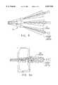
- FIG. 1shows an illustration of prior art forced air deicing system of the type disclosed in U.S. Pat. No. 5,244,168, that injects glycol A at right angles to the primary flow axis of an airstream B , generally producing what is described in that patent as "a well-dispersed atomized spray pattern" (col 7 line 35) or a “spray pattern of a high speed colloidal suspension of deicing fluid in air” (claim 1, lines 21-22).
- This patentalso requires the uses of a "plurality of sources of deicing fluid.” (see col 2, line 34 col line 32).
- glycol injected at a right angle to the primary axis of the airstreamreduces the effectiveness of forced air deicing.
- the glycolmixes and atomizes in the airstream.
- the energy transfer process associated with the mixing and atomizingreduces the kinetic energy of the airstream which reduces the effectiveness of the air stream/glycol mixture to dislodge snow and ice that is frozen to or adhered to an aircraft.
- this atomization processreduces the effectiveness of the airstream in breaking loose snow and ice that is frozen to or adhered to an aircraft surface and also reduces the effectiveness of the airstream in moving heavy, wet snow.
- the mixture of atomized glycol and high velocity airadds more wetness to the snow further inhibiting the removal of wet snow.
- U.S. Pat. No. 5,104,068 Krilla et al. for a "Apparatus and Method for De-Icing and Anti-Icing (and/or Cleaning and Rising Aircraft)"describes an apparatus for both de-icing and anti-icing an aircraft in one "pass".
- the apparatusconsists of articulated booms on each side of the aircraft to be processed. These booms are such that they extend over the entire length of each wing and each has two series of nozzles. One set is for dispensing a deicing fluid mixture and the other set of nozzles dispenses anti-icing fluid. There is also a set of booms underneath the aircraft for processing the lower aircraft surfaces.
- the patentalso describes the use of different mixtures of pressurized air, water and glycol (Type I) with the mixture varied in accordance with the particular weather conditions.
- the apparatus and process described aboveare commercially known by the name "Whisper Wash” expected to be field demonstrated during the winter of 1996-7. Benefits expected to be realized presumably include, reduced glycol usage and reduced de-ice/anti-ice cycle time.
- This inventionovercomes the disadvantage of the prior systems and provides a new hybrid deicing system that produces high velocity specially formed coaxial streams of Type I glycol and water (i.e., deicing fluid) and air for efficiently and effectively removing ice from an aircraft.
- This invention(“hybrid deicing"), utilizing two fluid flow technologies and a unique coaxial nozzle, yields an efficient, stand-alone deicing system, i.e. a complete deicing system that reduces glycol usage and deicing cycle time.
- the new processconsists of an inner high velocity stream of glycol surrounded by an outer stream of high velocity air.
- hybrid deicingcan quickly and safely remove snow and ice frozen to a simulated aircraft surface. These tests indicate that deicing glycol usage can be reduced to 10% or less relative to conventional usage thereby providing the deicing operator with significant economic and waste management benefits. It is estimated hybrid deicing will reduce conventional deicing cycle time, in many deicing situations, by 10% or more providing an additional benefit to the operator.
- the specially formed streamincludes a stream within a stream, wherein a deicing fluid such as glycol/water mixture is entrained within and encased by a surrounding jacket of entraining fluid such air.
- the unique coaxial nozzleproduces two essentially independent streams of Type I glycol fluid and air, both streams exiting the nozzle at high and substantially equal velocities in the range of 600-800 mph.
- the precise velocity of the streamsdepends on the upstream pressures and temperatures of the fluids.
- This inventionutilizing high pressure glycol that is coaxially injected into a high velocity airstream, will de-ice aircraft as effectively as the conventional hot glycol wash method but with glycol application rates reduced to 10% or less of conventional rates. Consequently, this new deicing system significantly reduces deicing costs and the impact on the environment.
- This inventionutilizing high pressure glycol that is coaxially injected into a high velocity airstream and or stream within a stream high pressured injection, will de-ice aircraft as effectively as the conventional hot glycol wash method but with glycol application rates reduced to 10% or less of conventional rates. Consequently, this new deicing system significantly reduces conventional deicing costs and the impact on the environment.
- FIG. 1is a cross sectional illustration of a prior glycol and forced air deicing system showing glycol injection at a right angle to the air stream.
- FIG. 2is an illustration of glycol forced air deicing system in accordance with the present invention showing coaxial glycol and injection.
- FIG. 3is an illustration of a coaxial nozzle exit in accordance with the present invention showing coaxial glycol injection.
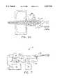
- FIG. 4is an illustration of schematic block diagram of a glycol and forced air deicing system in accordance with the present invention showing coaxial glycol injection.
- FIG. 5is an illustration of the sweeping action found to be effective in the use of the present invention.
- FIGS. 6a and 6bare illustrations of the frozen snow removal process in accordance with the present invention.
- FIG. 7is an illustration of a hybrid glycol and forced air deicing system in accordance with the present invention.
- FIG. 8is an illustration of a truck mounted hybrid deicing system in accordance with the present invention.
- FIG. 9.is an illustration of a stationary boom that can be used with the hybrid deicing system in accordance with the present invention.
- the new stand-alone ground based hybrid deicing system 10 of the present inventionutilizes a specially constructed coaxial nozzle assembly 20 that simultaneously delivers two independent, high velocity deicing streams.
- a deicing fluid streamis encased within a high velocity airstream.
- the nozzlepreferably has a 0.060 inch diameter carbide jetting orifice that produces a conical shaped jet.
- the coaxial nozzle assembly 20is specially designed to meld two fluid flow technologies, conversion of subsonic airflow to sonic or near sonic airflow and high pressure liquid jetting to create two independent streams that are effective for deicing aircraft.
- Coaxial nozzle assemblyhas two concentric pipes along the centerline of the assembly with low and high flow deicing fluid nozzles and a converging/air nozzle.
- the coaxial nozzle assembly 20comprises three concentric cylinders 22, 24, and 26 and three nozzles 32, 34 and 36. This cylindrical arrangement provides two different flow passages for the the deicing fluid and a single passage for the forced air.
- the outer cylinder 22, with a 3.5 inch internal diameter,has a converging/nozzle 32 at one end 38 where pressurized air 40 exits.
- the inner pipe 26delivers high pressure (up to 7000 psi) deicing fluid 42 at approximately 6 gpm to a fluid jetting nozzle 36 which produces a high velocity deicing fluid jet 44.
- the inside of the outer pipe 22 and outside of the inner pipe 26form an annular passage for low pressure deicing fluid in the pressure range of 150-300 psi.
- the low pressure deicing fluidpreferably exits the coaxial nozzle 20 through an annular array of orifices 34 at approximately 20 gpm in jets 48.
- the exits of the inner nozzles 34 and 36are flush with exit of the air nozzle 32.
- a key feature of the coaxial nozzleis the compatibility of the exit fluid streams.
- Pressurized air 40 from a centrifugal compressor (FIG. 7)enters the coaxial nozzle 20 at approximately 100 lb. per minute (ppm). This air 40 exits the coaxial nozzle 20 through the annular region formed by the convergent/nozzle 32 (ASME "long radius” nozzle) and the outer deicing fluid pipe 24.
- the ASME nozzle 32accelerates the air 40 to sonic or near sonic velocity with minimal energy loss.
- high pressure (7000 psi) deicing fluidflows through the inner pipe 26 and exits through a carbide fluid jetting nozzle 36 in a solid conical pattern.
- the coaxial nozzle design and inlet pressures of the air 40 and deicing fluid 42were selected to achieve equal exit velocities of approximately 600-800 mph for both fluids.
- the maximum flow rate of the deicing fluid 42/44is only 6 gallons per minute (gpm) relative to conventional deicing with flow rates of 60 gpm or more. Since, in the hybrid deicing process, the deicing fluid stream can be, turned “on” or “off abruptly by the deicing operator, glycol consumption is further reduced. For example, the deicing operator turns” off the deicing fluid when removing dry or near dry powder snow that is not adhered to the aircraft surface. After deicing under these conditions, the operator can turn "on" the deicing fluid to apply a final overspray of fluid for providing anti-icing holdover time prior to takeoff.
- gpmgallons per minute
- the purpose of the low pressure, high flow deicing fluid featureis to address the fairly infrequent but severe icing conditions that result in the formation of 1/4 inch or more of hard ice frozen to the aircraft surfaces. Under these conditions, a deicing process similar to conventional deicing (hot deicing fluid washdown) must be employed, i.e. thermal removal of the ice. The high velocity air flowing around this lower velocity inner stream assists in the snow removal process and also blows away the steam that forms. Therefore, the airstream has an added benefit of helping the operator to better see what he is doing. For hard, thick ice an operator switches the remote valves to direct the deicing fluid to the outer annual flow passage and the annular orifice array.
- the high pressure pumpis sped up so that the deicing fluid delivery is increased from 6 gpm to 20 gpm. Since the 20 gpm deicing fluid 46 now flows through a much larger orifice area, the pressure in the annular flow passage drops to 150-300 psi, hence the low pressure high flow mode of operation.
- FIG. 2shows the side view of the coaxial nozzle exit and the deicing fluid exit points for the two modes of operation using deicing fluid.
- a third mode of operationuses air only.
- FIG. 3.is an illustration of a the front view of the coaxial nozzle exit in accordance with the present invention.
- high velocity low flow deicing fluid 44is jetted from the center orifice 36 in a conical spray pattern.
- low velocity high flow deicing fluidflows through the annular orifices 34 at a rate of approximately 20 gpm.
- the inner deicing fluid stream 44 or 48is surrounded by a high velocity outer airstream 40.
- FIG. 4is an illustration of a schematic block diagram of a simplified glycol forced air deicing system 10 including deicing fluid tank 50 coupled to a high pressure pump 52. A copressor providing the forced air is not shown.
- a three way selector valve 54is coupled to the pump 52 to feedback deicer fluid to the tank 50 through return line 56 or to direct deicing fluids 42 or 46 to the nozzle assembly 20.
- a diverter valve 60is connected between the three way valve 54 and the low pressure deicing fluid passage so that when the diverter valve 56 is open a high volume of low pressure deicing fluid 46 flows to the orifices and 34.
- variable speed high pressure pump 52 of the system 10can be used for low flow (6 gpm) or high flow (20 gpm) operation in which deicing fluid flows coaxial to the airstream producing independent streams of fluids that work in concert and are effective in removing wet snow or snow ice that has adhered to the aircraft surfaces.
- a coaxial nozzle assembly 20(FIG. 2) can be constructed from 3.5 inch diameter stainless steel 22 tubing with a converging/ASME "long radius" nozzle 32 attached to one end.
- a second stainless steel pipe 26is supported along the centerline of the stainless steel pipe 24.
- a high pressure jetting nozzle assembly 36can be screwed into the end of this pipe 26.
- the nozzle assembly 36can include a carbide nozzle insert 64 that can be changed to alter the deicing fluid jet pattern for example from fan to solid cone with various dispersion angles.
- a system in accordance with the FIG. 4 schematic having a coaxial nozzle 20 and the remote controlled valves 54 and 60allows an operator of the deicing system to continuously adjust between all three deicing fluid modes or to select one of three deicing fluid flow modes: i) Low flow (6 gpm) for most deicing conditions, ii) High flow (20 gpm) for hard ice removal or iii) Flow "off for air only removal; deicing fluid is bypassed back to deicing fluid tank.
- FIG. 5is an illustration of the sweeping action found to be effective in the use of the present invention and shows the coaxial nozzle swinging motion found to be the most effective for removing ice.
- the coaxial nozzle swinging motionusing an automatic actuation system 74, can be activated when the deicing fluid 44/48 is called for by for instance depressing the lever of the deicing gun (FIG. 8).
- FIGS. 6a and 6bare illustrations of the frozen snow removal process in accordance with the present invention.
- frozen snowis removed by the concentrated energy of the inner deicing fluid stream.
- both streamwork in concert sweep away the loosened frozen snow.
- FIG. 7is a simplified schematic of a hybrid deicing system 10 in accordance with the present invention.
- a key element of the hybrid deicing system 10is the compact air source 41, such as a gear driven centrifugal compressor, manufactured by AlliedSignal as a model P3X compressor.
- This compressor 41is unique because of its very high power density, i.e. its high horsepower to low weight ratio.
- a high speed radial bladed impeller in this compressorproduces pressurized air at 100 ppm at a maximum pressure of 29 psig for sea level operation.
- These characteristics of the compressorare necessary to provide the air flow rate and discharge pressure at high altitude airports such as Denver International, as well as sea level airports, for effective hybrid deicing.
- the compactness of the machineallows it to be installed at the base of deicing booms to minimize air handling problems associated with air delivery through large diameter hose and pipe.
- high pressure deicing fluidis produced by a triplex type positive displacement variable speed pump 52 which has sufficient capacity to pump both low flow (6 gpm), high pressure (7000 psi) and high flow (20 gpm), low pressure (300 psi) deicing fluid.
- Both compressor 41 and high pressure pump 52are hydraulically driven with the ultimate power source being diesel engine 70.
- FIG. 8is an illustration of a truck mounted forced air deicing system in accordance with the present invention.
- FIG. 8below shows a deicer truck 80 with a hybrid deicing system 10 installed.
- the equipment shown in this schematicwould typically be installed in a deicer truck having a boom 92 (FIG. 8) or a ground mounted boom system 99 (FIG. 9.) such as the Ice Hawk system located at the Pittsburgh Airport.
- a deicing gun 82 including the coaxial nozzle 20is located at the boom basket 84 and the air compressor 41 is mounted at the base of the boom 80.
- a control system 90directly associated with the deicing process controls the deicing fluid valves (low flow, high flow or "off) and the speeds of the triplex pump 70 and compressor.
- FIG. 8illustrates an important feature of the hybrid deicing system 10, namely the location of the compact air source 41 (the gear driven centrifugal compressor) at the base of the deicing boom 92. This location minimizes air handling problems associated with air delivery through large diameter hose and pipe.
- a Type II antiicing system for gel coating cleaned aircraftcan also be included on the deicing trucks with the hybrid system 10.
- hybrid deicingresulting from its reduced deicing fluid usage, is the greater on station availability of the hybrid deicer truck.
- a deicer truck 80has a 2000 gallon Type I deicing fluid tank 50 that is refilled at the airline's maintenance facility usually far removed from where deicing is done, i.e. at the gate or near the takeoff area. Due to its low usage of deicing fluid, a hybrid deicer truck can deice about 10 times the number of aircraft that a conventional deicing truck can deice.
- a deicing fluid(glycol/water mixture) can be heated by a heater 101 and injected in the center of the airstream through a special 0.060 inch diameter jetting orifice at pressures up to 7,000 psi creating a conical shaped inner fluid stream of high velocity fluid which quickly penetrates and breaks loose ice and snow frozen to the aircraft surfaces.
- the concentrated force of this high velocity fluid streamis very effective in moving heavy, wet snow.
- the outer sheath of high velocity airthen works in concert with the inner stream of deicing fluid to hydrodynamically sweep away the ice and snow.
- Hybrid deicingincreaser the aerodynamic sweeping action of a high velocity airstream by adding to it an inner stream of a high velocity deicing fluid.
- This combination of an inner stream of high velocity deicing fluid within an outer stream of high velocity airhydrodynamically and thermally removes adhered ice, wet, light and heavy snow.
- the glycolis injected in the center of the airstream through a 0.060 inch diameter nozzle orifice at pressures up to 7,000 psi creating a dense and or highly condensed inner core of high velocity fluid which quickly penetrates and breaks loose ice and snow frozen to the aircraft surfaces.
- the outer sheath of high velocity airthen works in concert with the inner stream of glycol (i.e., deicing fluid) to hydrodynamically sweep away the ice and snow. Since the maximum flow rate of the glycol is only 6 gallons per minute (gpm) and the glycol stream can abruptly turned on or off by the deicing operator, glycol consumption is greatly reduced relatively to glycol consumption for conventional deicing.
- the deicing operatorturns on the glycol stream only when required by the deicing conditions, i.e. localized patches adhered ice/snow. Also, the operator can apply a final overspray of glycol after deicing, a conventional practice, for providing anti-icing prior to takeoff.
- the hybrid deicing processproduces coaxial streams of high velocity air and glycol that in combination have momentum and kinetic energy that are at least 50% higher than these same characteristics for the prior art fluid "spray pattern" (U.S. Pat. No. 5,244,168).
- the prior artinjects glycol transverse to the fluid "spray pattern” which does not change the momentum, but the kinetic energy is reduced.
- Fluid "stream within a stream” momentumis the primary mechanism for sweeping away loose snow and ice.
- Kinetic energyis the mechanism for breaking loose snow and ice that is frozen to the aircraft surfaces. Therefore, ample fluid "stream within a stream or coaxial stream” momentum and kinetic energy are necessary to provide effective deicing under all weather and deicing conditions.
Landscapes
- Engineering & Computer Science (AREA)
- Manufacturing & Machinery (AREA)
- Transportation (AREA)
- Aviation & Aerospace Engineering (AREA)
- Cleaning In General (AREA)
- Jet Pumps And Other Pumps (AREA)
Abstract
Description
Claims (27)
Priority Applications (4)
| Application Number | Priority Date | Filing Date | Title |
|---|---|---|---|
| US08/877,272US6047926A (en) | 1996-06-28 | 1997-06-17 | Hybrid deicing system and method of operation |
| US09/507,404US6293498B1 (en) | 1996-06-28 | 2000-02-18 | Hybrid deicing system and method of operation |
| US09/546,121US6360992B1 (en) | 1996-06-28 | 2000-04-10 | Hybrid deicing system and method of operation |
| US09/640,063US7431240B1 (en) | 1996-06-28 | 2000-08-17 | Hybrid deicing system and method of operation |
Applications Claiming Priority (2)
| Application Number | Priority Date | Filing Date | Title |
|---|---|---|---|
| US2250896P | 1996-06-28 | 1996-06-28 | |
| US08/877,272US6047926A (en) | 1996-06-28 | 1997-06-17 | Hybrid deicing system and method of operation |
Related Child Applications (2)
| Application Number | Title | Priority Date | Filing Date |
|---|---|---|---|
| US09/507,404ContinuationUS6293498B1 (en) | 1996-06-28 | 2000-02-18 | Hybrid deicing system and method of operation |
| US09/546,121Continuation-In-PartUS6360992B1 (en) | 1996-06-28 | 2000-04-10 | Hybrid deicing system and method of operation |
Publications (1)
| Publication Number | Publication Date |
|---|---|
| US6047926Atrue US6047926A (en) | 2000-04-11 |
Family
ID=26696009
Family Applications (3)
| Application Number | Title | Priority Date | Filing Date |
|---|---|---|---|
| US08/877,272Expired - LifetimeUS6047926A (en) | 1996-06-28 | 1997-06-17 | Hybrid deicing system and method of operation |
| US09/507,404Expired - LifetimeUS6293498B1 (en) | 1996-06-28 | 2000-02-18 | Hybrid deicing system and method of operation |
| US09/640,063Expired - Fee RelatedUS7431240B1 (en) | 1996-06-28 | 2000-08-17 | Hybrid deicing system and method of operation |
Family Applications After (2)
| Application Number | Title | Priority Date | Filing Date |
|---|---|---|---|
| US09/507,404Expired - LifetimeUS6293498B1 (en) | 1996-06-28 | 2000-02-18 | Hybrid deicing system and method of operation |
| US09/640,063Expired - Fee RelatedUS7431240B1 (en) | 1996-06-28 | 2000-08-17 | Hybrid deicing system and method of operation |
Country Status (1)
| Country | Link |
|---|---|
| US (3) | US6047926A (en) |
Cited By (15)
| Publication number | Priority date | Publication date | Assignee | Title |
|---|---|---|---|---|
| US6250588B1 (en)* | 1999-07-27 | 2001-06-26 | The United States Of America As Represented By The Secretary Of The Air Force | Forced air de-icing and washing system attached to the distal end of a boom |
| US6293498B1 (en) | 1996-06-28 | 2001-09-25 | Honeywell International Inc. | Hybrid deicing system and method of operation |
| US6360992B1 (en) | 1996-06-28 | 2002-03-26 | Honeywell International Inc. | Hybrid deicing system and method of operation |
| US6562256B1 (en)* | 2002-05-06 | 2003-05-13 | Nch Corporation | Self-dispersing particulate composition and methods of use |
| US6565758B1 (en) | 2000-03-21 | 2003-05-20 | The Centech Group, Inc. | Systems and methods for dispensing, collecting and processing wash fluid |
| US20060180678A1 (en)* | 2005-01-07 | 2006-08-17 | Meyer Products, Inc. | Deicing apparatus |
| US20070266591A1 (en)* | 2006-05-18 | 2007-11-22 | R.P. Scherer Technologies, Inc. | Nozzle structure |
| US20090242664A1 (en)* | 2008-03-25 | 2009-10-01 | Envirotech Services, Inc. | Device for spraying anti-icing agents on transport surface |
| US9221544B2 (en) | 2011-09-20 | 2015-12-29 | The Boeing Company | Integrated surface thermal management system |
| US20160090859A1 (en)* | 2014-09-25 | 2016-03-31 | Rolls-Royce Plc | Gas turbine engine and a method of washing a gas turbine engine |
| US20160199869A1 (en)* | 2013-08-13 | 2016-07-14 | Sames Technologies | Sprayer for a liquid coating product and spraying facility comprising such a sprayer |
| DE102017010723A1 (en)* | 2017-11-13 | 2019-05-16 | Cuma Kilic | Cleaning device for vehicle windows |
| US11725365B2 (en) | 2016-06-13 | 2023-08-15 | Esco Group Llc | Handling system for ground-engaging wear parts secured to earth working equipment |
| CN118008731A (en)* | 2024-03-13 | 2024-05-10 | 沈阳工业大学 | Wind-powered electricity generation blade icing high pressure atomizing efflux defroster |
| US12104361B2 (en) | 2018-12-10 | 2024-10-01 | Esco Group Llc | System and process for conducting in-field operations |
Families Citing this family (34)
| Publication number | Priority date | Publication date | Assignee | Title |
|---|---|---|---|---|
| IL159783A (en)* | 2004-01-08 | 2009-06-15 | Tavtech Ltd | High velocity liquid-gas mist tissue abrasion device |
| US7906722B2 (en) | 2005-04-19 | 2011-03-15 | Palo Alto Research Center Incorporated | Concentrating solar collector with solid optical element |
| US20070169806A1 (en)* | 2006-01-20 | 2007-07-26 | Palo Alto Research Center Incorporated | Solar cell production using non-contact patterning and direct-write metallization |
| US7765949B2 (en) | 2005-11-17 | 2010-08-03 | Palo Alto Research Center Incorporated | Extrusion/dispensing systems and methods |
| US7799371B2 (en)* | 2005-11-17 | 2010-09-21 | Palo Alto Research Center Incorporated | Extruding/dispensing multiple materials to form high-aspect ratio extruded structures |
| US20070107773A1 (en) | 2005-11-17 | 2007-05-17 | Palo Alto Research Center Incorporated | Bifacial cell with extruded gridline metallization |
| US7855335B2 (en)* | 2006-04-26 | 2010-12-21 | Palo Alto Research Center Incorporated | Beam integration for concentrating solar collector |
| US7851693B2 (en) | 2006-05-05 | 2010-12-14 | Palo Alto Research Center Incorporated | Passively cooled solar concentrating photovoltaic device |
| US7638708B2 (en) | 2006-05-05 | 2009-12-29 | Palo Alto Research Center Incorporated | Laminated solar concentrating photovoltaic device |
| US8322025B2 (en) | 2006-11-01 | 2012-12-04 | Solarworld Innovations Gmbh | Apparatus for forming a plurality of high-aspect ratio gridline structures |
| US8226391B2 (en) | 2006-11-01 | 2012-07-24 | Solarworld Innovations Gmbh | Micro-extrusion printhead nozzle with tapered cross-section |
| US7922471B2 (en) | 2006-11-01 | 2011-04-12 | Palo Alto Research Center Incorporated | Extruded structure with equilibrium shape |
| US7780812B2 (en) | 2006-11-01 | 2010-08-24 | Palo Alto Research Center Incorporated | Extrusion head with planarized edge surface |
| US7928015B2 (en) | 2006-12-12 | 2011-04-19 | Palo Alto Research Center Incorporated | Solar cell fabrication using extruded dopant-bearing materials |
| US7638438B2 (en) | 2006-12-12 | 2009-12-29 | Palo Alto Research Center Incorporated | Solar cell fabrication using extrusion mask |
| US7954449B2 (en) | 2007-05-08 | 2011-06-07 | Palo Alto Research Center Incorporated | Wiring-free, plumbing-free, cooled, vacuum chuck |
| US7999175B2 (en) | 2008-09-09 | 2011-08-16 | Palo Alto Research Center Incorporated | Interdigitated back contact silicon solar cells with laser ablated grooves |
| US8117983B2 (en)* | 2008-11-07 | 2012-02-21 | Solarworld Innovations Gmbh | Directional extruded bead control |
| US8704086B2 (en)* | 2008-11-07 | 2014-04-22 | Solarworld Innovations Gmbh | Solar cell with structured gridline endpoints vertices |
| US20100117254A1 (en)* | 2008-11-07 | 2010-05-13 | Palo Alto Research Center Incorporated | Micro-Extrusion System With Airjet Assisted Bead Deflection |
| US8080729B2 (en) | 2008-11-24 | 2011-12-20 | Palo Alto Research Center Incorporated | Melt planarization of solar cell bus bars |
| CA2745477A1 (en)* | 2008-12-05 | 2010-06-10 | Vestergaard Company A/S | De-icer for airplanes |
| US8960120B2 (en)* | 2008-12-09 | 2015-02-24 | Palo Alto Research Center Incorporated | Micro-extrusion printhead with nozzle valves |
| US8089216B2 (en)* | 2008-12-10 | 2012-01-03 | Linear Technology Corporation | Linearity in LED dimmer control |
| EP2454156B1 (en)* | 2009-07-16 | 2013-12-04 | Vestergaard Company A/S | Dynamic de-icing distance |
| EP2700308A1 (en)* | 2010-02-23 | 2014-02-26 | BASF Agro B.V., Arnhem (NL), Zürich Branch | Method of injecting pesticide in soil adjacent structures |
| US8769866B2 (en)* | 2010-02-23 | 2014-07-08 | BASF Agro B.V. | High pressure injection system for applying a pesticide beneath the surface of the ground |
| US8586129B2 (en) | 2010-09-01 | 2013-11-19 | Solarworld Innovations Gmbh | Solar cell with structured gridline endpoints and vertices |
| US9120190B2 (en) | 2011-11-30 | 2015-09-01 | Palo Alto Research Center Incorporated | Co-extruded microchannel heat pipes |
| US10371468B2 (en) | 2011-11-30 | 2019-08-06 | Palo Alto Research Center Incorporated | Co-extruded microchannel heat pipes |
| US8875653B2 (en) | 2012-02-10 | 2014-11-04 | Palo Alto Research Center Incorporated | Micro-extrusion printhead with offset orifices for generating gridlines on non-square substrates |
| CN107862116B (en)* | 2017-10-25 | 2021-11-02 | 国网湖南省电力公司 | A kind of parameter determination method of insulating air duct used for hot air deicing |
| CN113483513B (en)* | 2021-09-07 | 2021-11-09 | 中国空气动力研究与发展中心低速空气动力研究所 | Water-absorbable ice-shaped cutter, ice-shaped measuring device and ice-shaped measuring method |
| CN113483511B (en)* | 2021-09-07 | 2021-11-09 | 中国空气动力研究与发展中心低速空气动力研究所 | Ice-shaped cutter, ice-shaped measuring device and ice-shaped measuring method |
Citations (53)
| Publication number | Priority date | Publication date | Assignee | Title |
|---|---|---|---|---|
| US1868468A (en)* | 1930-10-11 | 1932-07-19 | Iceless Air Wing Corp | Heater for airplane wings |
| US1943062A (en)* | 1931-07-29 | 1934-01-09 | Edward A Driscoll | Means for preventing the formation of ice on airplanes and the like |
| US2249940A (en)* | 1937-04-14 | 1941-07-22 | Bulloch David Carnie | Prevention of ice formation on the wings or other parts of aircraft |
| US2312187A (en)* | 1941-08-29 | 1943-02-23 | Patterson Ind Inc | Windshield protector and cleaner for airplanes |
| US2390093A (en)* | 1944-03-16 | 1945-12-04 | Garrison Murray Ed | Airplane wing deicing means |
| US2406473A (en)* | 1943-09-03 | 1946-08-27 | Curtiss Wright Corp | Fan de-icing or anti-icing means |
| US2422746A (en)* | 1941-09-13 | 1947-06-24 | Patterson Ind Inc | Airplane wing deicer |
| US2457031A (en)* | 1942-12-05 | 1948-12-21 | Borg Warner | Aircraft anti-icing arrangement |
| US2832528A (en)* | 1953-10-01 | 1958-04-29 | Gen Motors Corp | Alcohol mist icing prevention |
| US2938509A (en)* | 1958-08-14 | 1960-05-31 | Motocycles Et Automobiles Soc | Mixers for two liquids, such as those for supplying engines with a mixture of fuel and lubricant |
| US3086713A (en)* | 1960-12-28 | 1963-04-23 | Hugh F Moldenhauer | Mobile sprayer apparatus |
| US3101175A (en)* | 1959-09-23 | 1963-08-20 | Wald Ind Inc | Road striping machine with electronic sight |
| US3160347A (en)* | 1963-03-27 | 1964-12-08 | Deere & Co | Highway sprayer |
| US3243123A (en)* | 1963-02-21 | 1966-03-29 | Fmc Corp | Spraying apparatus |
| US3485176A (en)* | 1967-04-28 | 1969-12-23 | Malsbary Mfg Co | Pumping system |
| US3533395A (en)* | 1968-08-12 | 1970-10-13 | Stanray Corp | Aircraft deicer system and apparatus |
| US3602211A (en)* | 1969-09-26 | 1971-08-31 | Walter Herbert Nelson Charman | Hot air generator unit |
| US3612075A (en)* | 1969-01-14 | 1971-10-12 | Vernon H Cook | Aircraft deicing apparatus |
| US3684186A (en)* | 1970-06-26 | 1972-08-15 | Ex Cell O Corp | Aerating fuel nozzle |
| US3777983A (en)* | 1971-12-16 | 1973-12-11 | Gen Electric | Gas cooled dual fuel air atomized fuel nozzle |
| US3835498A (en)* | 1972-07-14 | 1974-09-17 | L Arato | Craft washing plant |
| US4032090A (en)* | 1975-07-21 | 1977-06-28 | Thornton Trump Walter E | Method for deicing aircraft |
| US4073437A (en)* | 1976-06-11 | 1978-02-14 | Thorton Trump Walter Edmond | Conversion package for aircraft de-icing machines |
| US4118151A (en)* | 1974-04-03 | 1978-10-03 | Tokico Ltd. | Pump device |
| US4191348A (en)* | 1977-11-10 | 1980-03-04 | Holwerda-Huizenga Co. | Deicing system |
| US4221339A (en)* | 1977-12-03 | 1980-09-09 | Nakaya Sangyo Kabushiki Kaisha | Liquid spraying device |
| US4225086A (en)* | 1976-10-26 | 1980-09-30 | Bertil Sandell | Method and a device for adding material in an air stream to a nozzle |
| US4333607A (en)* | 1979-12-04 | 1982-06-08 | Fmc Corporation | Proportional mix system and method for applying a thixotropic de-icing fluid to an aircraft |
| US4378755A (en)* | 1977-01-12 | 1983-04-05 | Magnusson Ulla M | De-icing and cleaning system for aircrafts |
| US4634084A (en)* | 1984-03-09 | 1987-01-06 | De-Icing System K.B. | Aircraft de-icing system |
| US4652025A (en)* | 1984-06-15 | 1987-03-24 | Planetics Engineering, Inc. | Gimballed conduit connector |
| US4723733A (en)* | 1985-06-18 | 1988-02-09 | Mcclinchy William | Method of deicing commercial, military and private aircraft |
| US4741499A (en)* | 1984-12-31 | 1988-05-03 | The Boeing Company | Anti-icing system for aircraft |
| US4826107A (en)* | 1987-04-13 | 1989-05-02 | Thornton Trump Walter E | Aircraft deicing unit having rapid heating capability |
| US4842005A (en)* | 1988-01-26 | 1989-06-27 | Itt Corporation | Mixing apparatus and system |
| US4915300A (en)* | 1987-08-20 | 1990-04-10 | John Ryan | High pressure mixing and spray nozzle apparatus and method |
| US4932121A (en)* | 1988-06-04 | 1990-06-12 | Braun Aktiengesellschaft | Long-hair trimming device for dry shaving apparatus |
| US4986497A (en)* | 1989-06-16 | 1991-01-22 | Com-Pro Systems, Inc. | Aircraft-de-icing system |
| US5028017A (en)* | 1989-08-08 | 1991-07-02 | Federal Express Corporation | Mobile system for deicing aircraft |
| US5096145A (en)* | 1990-02-05 | 1992-03-17 | Fmc Corporation | Aircraft deicing apparatus and method |
| US5104068A (en)* | 1990-08-10 | 1992-04-14 | Krilla Ronald A | Apparatus and method for de-icing and anti-icing (and/or cleaning and rinsing) aircraft |
| US5134380A (en)* | 1986-02-10 | 1992-07-28 | Otakar Jonas | Icing detector and method |
| US5165606A (en)* | 1990-06-07 | 1992-11-24 | Asea Brown Boveri, Ltd. | Method for operating a pressure atomization nozzle |
| US5244168A (en)* | 1991-12-13 | 1993-09-14 | Williams Lee A | Methodology and apparatus for forced air aircraft deicing |
| US5282590A (en)* | 1990-12-28 | 1994-02-01 | Zwick Eugene B | Method and apparatus for heating and delivering deicing fluids |
| US5337961A (en)* | 1992-12-07 | 1994-08-16 | General Electric Company | Ceramic tip and compliant attachment interface for a gas turbine fuel nozzle |
| US5454532A (en)* | 1993-01-15 | 1995-10-03 | Fmc Corporation | Aircraft deicer pumping system |
| US5520331A (en)* | 1994-09-19 | 1996-05-28 | The United States Of America As Represented By The Secretary Of The Navy | Liquid atomizing nozzle |
| US5632072A (en)* | 1988-04-14 | 1997-05-27 | International Paper Company | Method for hydropatterning napped fabric |
| US5730806A (en)* | 1993-08-30 | 1998-03-24 | The United States Of America As Represented By The Administrator Of The National Aeronautics & Space Administration | Gas-liquid supersonic cleaning and cleaning verification spray system |
| US5746396A (en)* | 1994-10-21 | 1998-05-05 | Baltab Holdings, Ltd. | Deicer |
| US5779158A (en)* | 1996-04-16 | 1998-07-14 | National Foam, Inc. | Nozzle for use with fire-fighting foams |
| US5785721A (en)* | 1997-01-31 | 1998-07-28 | Texaco Inc. | Fuel injector nozzle with preheat sheath for reducing thermal shock damage |
Family Cites Families (27)
| Publication number | Priority date | Publication date | Assignee | Title |
|---|---|---|---|---|
| DE767362C (en) | 1941-07-20 | 1952-06-13 | Alfred Kaercher Dipl Ing | Method and device for removing snow and ice covers, in particular from supporting and guide surfaces |
| GB822811A (en) | 1956-02-14 | 1959-11-04 | British Europ Airways Corp | Improved apparatus for de-frosting the external surfaces of aircraft or other surfaces needing similar treatment |
| FR1149351A (en) | 1956-05-04 | 1957-12-24 | Chantiers & Ateliers De Constr | Device for controlling the operation of a lifting device |
| DE1266137B (en) | 1965-07-10 | 1968-04-11 | Hamburger Flugzeugbau G M B H | Extendable lift surface for longitudinal stabilization of aircraft |
| US3770062A (en) | 1970-10-12 | 1973-11-06 | American Fire App | Fire fighting apparatus |
| US3684185A (en) | 1970-11-13 | 1972-08-15 | Avon Prod Inc | Valve actuator |
| BE804040A (en) | 1972-08-28 | 1973-12-17 | Dustbane Enterprises Ltd | AIRCRAFT DEFROSTING EQUIPMENT |
| US4007793A (en) | 1975-08-25 | 1977-02-15 | Hux Fred M | Fire fighting apparatus |
| US3985223A (en) | 1975-09-22 | 1976-10-12 | Fmc Corporation | Universal gripper assembly for frozen confections |
| FR2406775A1 (en) | 1977-10-19 | 1979-05-18 | Fmc Europe | QUICK DISCONNECT COUPLING DEVICE FOR CRYOGENIC APPLICATIONS |
| US4423980A (en)* | 1981-04-23 | 1984-01-03 | Warnock Denny F | Truck-mounted apparatus for repairing asphalt |
| DE3126243C2 (en)* | 1981-07-03 | 1984-12-13 | M.A.N. Maschinenfabrik Augsburg-Nürnberg AG, 8500 Nürnberg | Power take-off of an internal combustion engine |
| DK157064C (en) | 1981-12-08 | 1990-04-30 | Godtfred Vestergaard | DEVICES FOR DEFICTION OF AIRCRAFT |
| US4872501A (en) | 1986-03-17 | 1989-10-10 | Fmc Corporation | Heat exchanger for mobile aircraft deicing machine and method of use |
| US5098036A (en) | 1986-10-30 | 1992-03-24 | Zwick Energy Research Organization, Inc. | Flameless deicer |
| US5134266A (en)* | 1990-10-26 | 1992-07-28 | Peppard Dennis L | Mobile deicing apparatus |
| US5224168A (en)* | 1991-05-08 | 1993-06-29 | Sri International | Method and apparatus for the active reduction of compression waves |
| US5180122A (en) | 1991-05-10 | 1993-01-19 | Fmc Corporation | Apparatus for deicing |
| US5318254A (en) | 1991-06-28 | 1994-06-07 | Conceptual Solutions, Inc. | Aircraft maintenance robot |
| US5549246A (en)* | 1992-10-26 | 1996-08-27 | Glas-Craft, Inc. | External mix application system and nozzle assembly |
| US5520311A (en) | 1994-07-11 | 1996-05-28 | Lam; Peter A.-F. | Garment hanger assembly kit |
| DE19522881C1 (en) | 1995-06-23 | 1996-11-28 | Kaercher Gmbh & Co Alfred | Device for treating an object |
| US6047926A (en) | 1996-06-28 | 2000-04-11 | Alliedsignal Inc. | Hybrid deicing system and method of operation |
| US5755404A (en) | 1996-09-30 | 1998-05-26 | The United States Of America As Represented By The Secretary Of The Air Force | Forced air aircraft de-icer system |
| US6045092A (en) | 1998-08-05 | 2000-04-04 | Fmc Corporation | Apparatus and method for deicing aircraft |
| US6547187B2 (en) | 1998-08-05 | 2003-04-15 | Fmc Technologies, Inc. | Apparatus and method for deicing aircraft using compact, lightweight air source |
| US6250588B1 (en) | 1999-07-27 | 2001-06-26 | The United States Of America As Represented By The Secretary Of The Air Force | Forced air de-icing and washing system attached to the distal end of a boom |
- 1997
- 1997-06-17USUS08/877,272patent/US6047926A/ennot_activeExpired - Lifetime
- 2000
- 2000-02-18USUS09/507,404patent/US6293498B1/ennot_activeExpired - Lifetime
- 2000-08-17USUS09/640,063patent/US7431240B1/ennot_activeExpired - Fee Related
Patent Citations (53)
| Publication number | Priority date | Publication date | Assignee | Title |
|---|---|---|---|---|
| US1868468A (en)* | 1930-10-11 | 1932-07-19 | Iceless Air Wing Corp | Heater for airplane wings |
| US1943062A (en)* | 1931-07-29 | 1934-01-09 | Edward A Driscoll | Means for preventing the formation of ice on airplanes and the like |
| US2249940A (en)* | 1937-04-14 | 1941-07-22 | Bulloch David Carnie | Prevention of ice formation on the wings or other parts of aircraft |
| US2312187A (en)* | 1941-08-29 | 1943-02-23 | Patterson Ind Inc | Windshield protector and cleaner for airplanes |
| US2422746A (en)* | 1941-09-13 | 1947-06-24 | Patterson Ind Inc | Airplane wing deicer |
| US2457031A (en)* | 1942-12-05 | 1948-12-21 | Borg Warner | Aircraft anti-icing arrangement |
| US2406473A (en)* | 1943-09-03 | 1946-08-27 | Curtiss Wright Corp | Fan de-icing or anti-icing means |
| US2390093A (en)* | 1944-03-16 | 1945-12-04 | Garrison Murray Ed | Airplane wing deicing means |
| US2832528A (en)* | 1953-10-01 | 1958-04-29 | Gen Motors Corp | Alcohol mist icing prevention |
| US2938509A (en)* | 1958-08-14 | 1960-05-31 | Motocycles Et Automobiles Soc | Mixers for two liquids, such as those for supplying engines with a mixture of fuel and lubricant |
| US3101175A (en)* | 1959-09-23 | 1963-08-20 | Wald Ind Inc | Road striping machine with electronic sight |
| US3086713A (en)* | 1960-12-28 | 1963-04-23 | Hugh F Moldenhauer | Mobile sprayer apparatus |
| US3243123A (en)* | 1963-02-21 | 1966-03-29 | Fmc Corp | Spraying apparatus |
| US3160347A (en)* | 1963-03-27 | 1964-12-08 | Deere & Co | Highway sprayer |
| US3485176A (en)* | 1967-04-28 | 1969-12-23 | Malsbary Mfg Co | Pumping system |
| US3533395A (en)* | 1968-08-12 | 1970-10-13 | Stanray Corp | Aircraft deicer system and apparatus |
| US3612075A (en)* | 1969-01-14 | 1971-10-12 | Vernon H Cook | Aircraft deicing apparatus |
| US3602211A (en)* | 1969-09-26 | 1971-08-31 | Walter Herbert Nelson Charman | Hot air generator unit |
| US3684186A (en)* | 1970-06-26 | 1972-08-15 | Ex Cell O Corp | Aerating fuel nozzle |
| US3777983A (en)* | 1971-12-16 | 1973-12-11 | Gen Electric | Gas cooled dual fuel air atomized fuel nozzle |
| US3835498A (en)* | 1972-07-14 | 1974-09-17 | L Arato | Craft washing plant |
| US4118151A (en)* | 1974-04-03 | 1978-10-03 | Tokico Ltd. | Pump device |
| US4032090A (en)* | 1975-07-21 | 1977-06-28 | Thornton Trump Walter E | Method for deicing aircraft |
| US4073437A (en)* | 1976-06-11 | 1978-02-14 | Thorton Trump Walter Edmond | Conversion package for aircraft de-icing machines |
| US4225086A (en)* | 1976-10-26 | 1980-09-30 | Bertil Sandell | Method and a device for adding material in an air stream to a nozzle |
| US4378755A (en)* | 1977-01-12 | 1983-04-05 | Magnusson Ulla M | De-icing and cleaning system for aircrafts |
| US4191348A (en)* | 1977-11-10 | 1980-03-04 | Holwerda-Huizenga Co. | Deicing system |
| US4221339A (en)* | 1977-12-03 | 1980-09-09 | Nakaya Sangyo Kabushiki Kaisha | Liquid spraying device |
| US4333607A (en)* | 1979-12-04 | 1982-06-08 | Fmc Corporation | Proportional mix system and method for applying a thixotropic de-icing fluid to an aircraft |
| US4634084A (en)* | 1984-03-09 | 1987-01-06 | De-Icing System K.B. | Aircraft de-icing system |
| US4652025A (en)* | 1984-06-15 | 1987-03-24 | Planetics Engineering, Inc. | Gimballed conduit connector |
| US4741499A (en)* | 1984-12-31 | 1988-05-03 | The Boeing Company | Anti-icing system for aircraft |
| US4723733A (en)* | 1985-06-18 | 1988-02-09 | Mcclinchy William | Method of deicing commercial, military and private aircraft |
| US5134380A (en)* | 1986-02-10 | 1992-07-28 | Otakar Jonas | Icing detector and method |
| US4826107A (en)* | 1987-04-13 | 1989-05-02 | Thornton Trump Walter E | Aircraft deicing unit having rapid heating capability |
| US4915300A (en)* | 1987-08-20 | 1990-04-10 | John Ryan | High pressure mixing and spray nozzle apparatus and method |
| US4842005A (en)* | 1988-01-26 | 1989-06-27 | Itt Corporation | Mixing apparatus and system |
| US5632072A (en)* | 1988-04-14 | 1997-05-27 | International Paper Company | Method for hydropatterning napped fabric |
| US4932121A (en)* | 1988-06-04 | 1990-06-12 | Braun Aktiengesellschaft | Long-hair trimming device for dry shaving apparatus |
| US4986497A (en)* | 1989-06-16 | 1991-01-22 | Com-Pro Systems, Inc. | Aircraft-de-icing system |
| US5028017A (en)* | 1989-08-08 | 1991-07-02 | Federal Express Corporation | Mobile system for deicing aircraft |
| US5096145A (en)* | 1990-02-05 | 1992-03-17 | Fmc Corporation | Aircraft deicing apparatus and method |
| US5165606A (en)* | 1990-06-07 | 1992-11-24 | Asea Brown Boveri, Ltd. | Method for operating a pressure atomization nozzle |
| US5104068A (en)* | 1990-08-10 | 1992-04-14 | Krilla Ronald A | Apparatus and method for de-icing and anti-icing (and/or cleaning and rinsing) aircraft |
| US5282590A (en)* | 1990-12-28 | 1994-02-01 | Zwick Eugene B | Method and apparatus for heating and delivering deicing fluids |
| US5244168A (en)* | 1991-12-13 | 1993-09-14 | Williams Lee A | Methodology and apparatus for forced air aircraft deicing |
| US5337961A (en)* | 1992-12-07 | 1994-08-16 | General Electric Company | Ceramic tip and compliant attachment interface for a gas turbine fuel nozzle |
| US5454532A (en)* | 1993-01-15 | 1995-10-03 | Fmc Corporation | Aircraft deicer pumping system |
| US5730806A (en)* | 1993-08-30 | 1998-03-24 | The United States Of America As Represented By The Administrator Of The National Aeronautics & Space Administration | Gas-liquid supersonic cleaning and cleaning verification spray system |
| US5520331A (en)* | 1994-09-19 | 1996-05-28 | The United States Of America As Represented By The Secretary Of The Navy | Liquid atomizing nozzle |
| US5746396A (en)* | 1994-10-21 | 1998-05-05 | Baltab Holdings, Ltd. | Deicer |
| US5779158A (en)* | 1996-04-16 | 1998-07-14 | National Foam, Inc. | Nozzle for use with fire-fighting foams |
| US5785721A (en)* | 1997-01-31 | 1998-07-28 | Texaco Inc. | Fuel injector nozzle with preheat sheath for reducing thermal shock damage |
Cited By (21)
| Publication number | Priority date | Publication date | Assignee | Title |
|---|---|---|---|---|
| US7431240B1 (en) | 1996-06-28 | 2008-10-07 | Honeywell International Inc. | Hybrid deicing system and method of operation |
| US6293498B1 (en) | 1996-06-28 | 2001-09-25 | Honeywell International Inc. | Hybrid deicing system and method of operation |
| US6360992B1 (en) | 1996-06-28 | 2002-03-26 | Honeywell International Inc. | Hybrid deicing system and method of operation |
| US6250588B1 (en)* | 1999-07-27 | 2001-06-26 | The United States Of America As Represented By The Secretary Of The Air Force | Forced air de-icing and washing system attached to the distal end of a boom |
| US6565758B1 (en) | 2000-03-21 | 2003-05-20 | The Centech Group, Inc. | Systems and methods for dispensing, collecting and processing wash fluid |
| US6562256B1 (en)* | 2002-05-06 | 2003-05-13 | Nch Corporation | Self-dispersing particulate composition and methods of use |
| US20030205692A1 (en)* | 2002-05-06 | 2003-11-06 | Fleming Wayne Anthony | Self-dispersing particulate composition and methods of use |
| US7588195B2 (en)* | 2005-01-07 | 2009-09-15 | Louis Berkman Winter Products | Deicing apparatus |
| US20060180678A1 (en)* | 2005-01-07 | 2006-08-17 | Meyer Products, Inc. | Deicing apparatus |
| US7575182B2 (en)* | 2006-05-18 | 2009-08-18 | R.P. Scherer Technologies, Inc. | Nozzle structure |
| US20070266591A1 (en)* | 2006-05-18 | 2007-11-22 | R.P. Scherer Technologies, Inc. | Nozzle structure |
| US20090242664A1 (en)* | 2008-03-25 | 2009-10-01 | Envirotech Services, Inc. | Device for spraying anti-icing agents on transport surface |
| US7798432B2 (en) | 2008-03-25 | 2010-09-21 | Envirotech Services, Inc. | Device for spraying anti-icing agents on transport surface |
| US9221544B2 (en) | 2011-09-20 | 2015-12-29 | The Boeing Company | Integrated surface thermal management system |
| US20160199869A1 (en)* | 2013-08-13 | 2016-07-14 | Sames Technologies | Sprayer for a liquid coating product and spraying facility comprising such a sprayer |
| US20160090859A1 (en)* | 2014-09-25 | 2016-03-31 | Rolls-Royce Plc | Gas turbine engine and a method of washing a gas turbine engine |
| US11725365B2 (en) | 2016-06-13 | 2023-08-15 | Esco Group Llc | Handling system for ground-engaging wear parts secured to earth working equipment |
| DE102017010723A1 (en)* | 2017-11-13 | 2019-05-16 | Cuma Kilic | Cleaning device for vehicle windows |
| DE102017010723B4 (en)* | 2017-11-13 | 2021-03-18 | Cuma Kilic | Cleaning device for motor vehicle windows |
| US12104361B2 (en) | 2018-12-10 | 2024-10-01 | Esco Group Llc | System and process for conducting in-field operations |
| CN118008731A (en)* | 2024-03-13 | 2024-05-10 | 沈阳工业大学 | Wind-powered electricity generation blade icing high pressure atomizing efflux defroster |
Also Published As
| Publication number | Publication date |
|---|---|
| US7431240B1 (en) | 2008-10-07 |
| US6293498B1 (en) | 2001-09-25 |
Similar Documents
| Publication | Publication Date | Title |
|---|---|---|
| US6047926A (en) | Hybrid deicing system and method of operation | |
| US5244168A (en) | Methodology and apparatus for forced air aircraft deicing | |
| RU2345345C1 (en) | Method of land trials of objects of aviation technics which are exposed to icing and device for its realisation | |
| US6250588B1 (en) | Forced air de-icing and washing system attached to the distal end of a boom | |
| RU2554188C2 (en) | Aircraft gas turbine engine flushing system | |
| US5104068A (en) | Apparatus and method for de-icing and anti-icing (and/or cleaning and rinsing) aircraft | |
| US3759330A (en) | Fire extinguishing method | |
| EP0007958A1 (en) | A de-icing and cleaning system for aircraft or trains. | |
| US6360992B1 (en) | Hybrid deicing system and method of operation | |
| CN106677113A (en) | Airport spray vehicle | |
| CN109322272A (en) | Supersonic axial whirlpool is blown sled | |
| US5755404A (en) | Forced air aircraft de-icer system | |
| CN109131931B (en) | Deicing system and deicing method for aircraft | |
| GB2516652A (en) | Cleaning surfaces | |
| US6378807B1 (en) | Aircraft installed snow remover | |
| KR101164647B1 (en) | Mist diminution and interception system of road and bridge | |
| US3199506A (en) | Device for clearing wide roads or runways covered with snow and ice | |
| CN206800304U (en) | A kind of function jet snow removing vehicle | |
| RU2273008C1 (en) | Method for simulation of natural conditions of operation of objects of aviation materiel subjected to icing | |
| CN106284180A (en) | A kind of ice and snow applying jet-flow deicing eliminates car | |
| CN212327765U (en) | Vehicle-mounted dust suppression working machine | |
| RU2276218C1 (en) | Gas-jet machine | |
| JPH0634836Y2 (en) | Coanda fluid ejector | |
| WO1995001278A1 (en) | Methodology and apparatus for forced air aircraft deicing | |
| RU2118552C1 (en) | Fire-extinguishing unit |
Legal Events
| Date | Code | Title | Description |
|---|---|---|---|
| AS | Assignment | Owner name:ALLIEDSIGNAL INC., NEW JERSEY Free format text:ASSIGNMENT OF ASSIGNORS INTEREST;ASSIGNORS:STANKO, JOHN;PEARSON, LOWELL;REEL/FRAME:008895/0195 Effective date:19970908 | |
| FEPP | Fee payment procedure | Free format text:PAYOR NUMBER ASSIGNED (ORIGINAL EVENT CODE: ASPN); ENTITY STATUS OF PATENT OWNER: LARGE ENTITY | |
| AS | Assignment | Owner name:HONEYWELL INTERNATIONAL INC., NEW JERSEY Free format text:MERGER;ASSIGNOR:ALLIEDSIGNAL INC.;REEL/FRAME:011582/0766 Effective date:19991201 | |
| FPAY | Fee payment | Year of fee payment:4 | |
| FPAY | Fee payment | Year of fee payment:8 | |
| REMI | Maintenance fee reminder mailed | ||
| LAPS | Lapse for failure to pay maintenance fees | ||
| FP | Lapsed due to failure to pay maintenance fee | Effective date:20120411 | |
| FEPP | Fee payment procedure | Free format text:PETITION RELATED TO MAINTENANCE FEES DISMISSED (ORIGINAL EVENT CODE: PMFS); ENTITY STATUS OF PATENT OWNER: LARGE ENTITY | |
| FEPP | Fee payment procedure | Free format text:PETITION RELATED TO MAINTENANCE FEES FILED (ORIGINAL EVENT CODE: PMFP); ENTITY STATUS OF PATENT OWNER: LARGE ENTITY | |
| AS | Assignment | Owner name:PREMIER ENGINEERING AND MANUFACTURING INC., WISCON Free format text:ASSIGNMENT OF ASSIGNORS INTEREST;ASSIGNOR:HONEYWELL INTERNATIONAL INC.;REEL/FRAME:038358/0332 Effective date:20081205 | |
| FEPP | Fee payment procedure | Free format text:PETITION RELATED TO MAINTENANCE FEES FILED (ORIGINAL EVENT CODE: PMFP); ENTITY STATUS OF PATENT OWNER: LARGE ENTITY | |
| FEPP | Fee payment procedure | Free format text:SURCHARGE, PETITION TO ACCEPT PYMT AFTER EXP, UNINTENTIONAL. (ORIGINAL EVENT CODE: M2558); ENTITY STATUS OF PATENT OWNER: LARGE ENTITY Free format text:PETITION RELATED TO MAINTENANCE FEES GRANTED (ORIGINAL EVENT CODE: PMFG) | |
| MAFP | Maintenance fee payment | Free format text:PAYMENT OF MAINTENANCE FEE, 12TH YR, SMALL ENTITY (ORIGINAL EVENT CODE: M2553) Year of fee payment:12 | |
| PRDP | Patent reinstated due to the acceptance of a late maintenance fee | Effective date:20170925 | |
| STCF | Information on status: patent grant | Free format text:PATENTED CASE |