US6047816A - Printhead container and method - Google Patents
Printhead container and methodDownload PDFInfo
- Publication number
- US6047816A US6047816AUS09/149,701US14970198AUS6047816AUS 6047816 AUS6047816 AUS 6047816AUS 14970198 AUS14970198 AUS 14970198AUS 6047816 AUS6047816 AUS 6047816A
- Authority
- US
- United States
- Prior art keywords
- enclosure
- ink
- printhead
- channel
- interior
- Prior art date
- Legal status (The legal status is an assumption and is not a legal conclusion. Google has not performed a legal analysis and makes no representation as to the accuracy of the status listed.)
- Expired - Lifetime
Links
Images


Classifications
- B—PERFORMING OPERATIONS; TRANSPORTING
- B41—PRINTING; LINING MACHINES; TYPEWRITERS; STAMPS
- B41J—TYPEWRITERS; SELECTIVE PRINTING MECHANISMS, i.e. MECHANISMS PRINTING OTHERWISE THAN FROM A FORME; CORRECTION OF TYPOGRAPHICAL ERRORS
- B41J2/00—Typewriters or selective printing mechanisms characterised by the printing or marking process for which they are designed
- B41J2/005—Typewriters or selective printing mechanisms characterised by the printing or marking process for which they are designed characterised by bringing liquid or particles selectively into contact with a printing material
- B41J2/01—Ink jet
- B41J2/17—Ink jet characterised by ink handling
- B41J2/175—Ink supply systems ; Circuit parts therefor
- B41J2/17503—Ink cartridges
- B41J2/17533—Storage or packaging of ink cartridges
- B—PERFORMING OPERATIONS; TRANSPORTING
- B65—CONVEYING; PACKING; STORING; HANDLING THIN OR FILAMENTARY MATERIAL
- B65D—CONTAINERS FOR STORAGE OR TRANSPORT OF ARTICLES OR MATERIALS, e.g. BAGS, BARRELS, BOTTLES, BOXES, CANS, CARTONS, CRATES, DRUMS, JARS, TANKS, HOPPERS, FORWARDING CONTAINERS; ACCESSORIES, CLOSURES, OR FITTINGS THEREFOR; PACKAGING ELEMENTS; PACKAGES
- B65D81/00—Containers, packaging elements, or packages, for contents presenting particular transport or storage problems, or adapted to be used for non-packaging purposes after removal of contents
- B65D81/18—Containers, packaging elements, or packages, for contents presenting particular transport or storage problems, or adapted to be used for non-packaging purposes after removal of contents providing specific environment for contents, e.g. temperature above or below ambient
- B65D81/20—Containers, packaging elements, or packages, for contents presenting particular transport or storage problems, or adapted to be used for non-packaging purposes after removal of contents providing specific environment for contents, e.g. temperature above or below ambient under vacuum or superatmospheric pressure, or in a special atmosphere, e.g. of inert gas
- B65D81/2046—Containers, packaging elements, or packages, for contents presenting particular transport or storage problems, or adapted to be used for non-packaging purposes after removal of contents providing specific environment for contents, e.g. temperature above or below ambient under vacuum or superatmospheric pressure, or in a special atmosphere, e.g. of inert gas under superatmospheric pressure
- B65D81/2053—Containers, packaging elements, or packages, for contents presenting particular transport or storage problems, or adapted to be used for non-packaging purposes after removal of contents providing specific environment for contents, e.g. temperature above or below ambient under vacuum or superatmospheric pressure, or in a special atmosphere, e.g. of inert gas under superatmospheric pressure in an least partially rigid container
Definitions
- This inventiongenerally relates to packaging apparatus and methods and more particularly relates to a container and method for a printhead having ink therein, the container adapted to prevent leakage of the ink from the printhead during transportation or storage of the printhead.
- an inkjet printhead with an internal ink reservoiris transported from place of manufacture, it is typically transported with no ink in the reservoir. That is, the printhead is typically shipped empty. The printhead is transported empty to avoid spilling of ink during transport. It is only after the printhead reaches its destination, that the user of the printhead fills the reservoir with ink.
- One technique for overcoming this problemis for the manufacturer of the printhead to fill the reservoir and cover the nozzles with adhesive tape before the printhead is shipped to the user. Once the printhead reaches its destination, the user removes the tape before inserting the printhead into the printer. However, removing the tape may damage the nozzle plate, particularly when the nozzles include MEMS (Micro-Electro Mechanical Systems). Also, the adhesive tape may deposit residual amounts of adhesive on the nozzle plate during removal of the tape. Such residual amounts of adhesive may interfere with proper operation of the printhead. Thus, another problem in the art is damage to the MEMS and deposit of residual amounts of adhesive on the nozzle plate as the adhesive tape is removed from the nozzle plate.
- MEMSMicro-Electro Mechanical Systems
- An object of the present inventionis to provide a container for a printhead having ink therein, the container adapted to prevent leakage of the ink from the printhead during transportation or storage of the printhead.
- the present inventionresides in, for use in association with a printer, a container for a fluid-carrying body having a channel terminating in an orifice, the channel having a fluid therein, the container comprising an enclosure surrounding the fluid-carrying body, said enclosure capable of being pressurized to a predetermined internal pressure, the internal pressure acting on the fluid to retain the fluid in the channel, so that the fluid is prevented from flowing along the channel and through the orifice.
- a feature of the present inventionis the provision of an enclosure surrounding an inkjet printhead for pressurizing the printhead, so that ink does not leak therefrom during transportation or storage of the printhead.
- An advantage of the present inventionis that an ink reservoir belonging to the printhead is filled before the printhead is shipped to the user in order to avoid inadvertent introduction of air bubbles and debris into the reservoir which may otherwise occur if the reservoir is filled by the user.
- Another advantage of the present inventionis that use thereof avoids need to apply adhesive tape and thus avoids damage to the nozzle plate and MEMS by avoiding deposit of residual amounts of adhesive on the nozzle plate as the adhesive tape is removed therefrom.
- FIG. 1is a view in perspective of an ink jet printhead, with parts removed for clarity;
- FIG. 2is a view in perspective of the printhead surrounded by a first embodiment pressurized enclosure shown in phantom, the printhead having a nozzle plate present, which nozzle plate has a plurality of nozzle orifices formed therein;
- FIG. 3is a view in elevation of the printhead surrounded by the enclosure
- FIG. 4is a view along section line 4--4 of FIG. 3;
- FIG. 5is a view along section line 5--5 of FIG. 3;
- FIG. 6is an enlarged fragmentation view in vertical section of one of the nozzle orifices and adjacent structure
- FIG. 7is a view in perspective of a second embodiment of the enclosure surrounding the printhead, this second embodiment including a support frame for constraining lateral movement of the printhead;
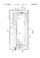
- FIG. 8is a view in horizontal section of the second embodiment of the invention.
- Printhead 5comprises a printhead body 10 having a plurality of elongated parallel ink channels 20 extending therethrough. Each channel 20 has ink 23 therein. More specifically, each channel 20 is defined by an open side 25, opposing sidewall portions 30a and 30b, and a base portion 35 interconnecting sidewall portions 30a and 30b. A top plate 40 sealingly caps all channels 20 and open sides 25, so that ink 23 is prevented from escaping channels 20 by way of open sides 25.
- printhead body 10has a front surface 45 to which a nozzle plate 50 is sealingly attached.
- Nozzle plate 50is sealingly attached to printhead body 10 in a manner that prevents ink 23 from leaking from printhead 5 at the interface defined by printhead body 10 and nozzle plate 50.
- Nozzle plate 50includes a plurality of generally circular nozzle orifices 55 therethrough of predetermined nozzle radius "Nr," each orifice 55 being aligned with a respective one of channels 20.
- a purpose of orifice 55is to control direction of an ink droplet (not shown) to be ejected from orifice 55, so that the ink droplet is ejected generally perpendicularly with respect to nozzle plate 50 in order to form a suitable image (not shown) on a receiver (also not shown).
- a single ink reservoir 60 defining a cavity 65 therein in communication with all channels 20is provided for holding a supply of ink 23.
- an opening 67is formed in reservoir 60 for allowing ink 23 to be supplied into cavity 65.
- a plug 69is sized to sealingly engage opening 67 after a desired amount of ink 23 is supplied into cavity 65.
- ink 23already be present in cavity 65 for user convenience. This is preferable to requiring the user to load ink 23 into reservoir 60, which would inconvenience the user. Also, it is desirable to fill printhead 5 with ink 23 prior to shipment of printhead 5 in order to avoid introduction of air bubbles and debris into reservoir 60 by the user. However, loading printhead 5 with ink 23 before shipment may result in leaking of ink through orifices 55 during transit or storage of printhead 5. It is therefore highly desirable to prevent leakage of ink 23 from printhead 5 during transit or storage of printhead 5.
- an ink meniscus 70 of radius "R"will form at each of orifices 55 when printhead 5 is loaded with ink 23 prior to shipment. Unless proper precaution is taken, ink 23 will leak, seep and/or weep from orifices 55 because pressure inside reservoir 60 and channels 20 may in some circumstances equal or exceed the pressure outside reservoir 60 and channels 20. For example, if reservoir 60 is filled at atmospheric pressure, at sea level, then the atmospheric pressure acting on reservoir 60 and channels 20 is defined herein as P atm (equal to 33.5 feet of water, or 100 Kilo Pascals (KPa)). The pressure inside reservoir 60 and channel 20 at meniscus 70 will equal:
- gis the acceleration of gravity
- his the vertical height of liquid ink above meniscus 70.
- ⁇is the surface tension of the ink
- Dis the diameter of the orifice.
- enclosure 80being leakproof, protects the open nozzles 55 from external pressure drops due, for example, to transportation at high altitudes.
- the amount of excess pressurization of the package interior over the pressure at which the reservoir is filled and cappedcan be taken as equal to or greater than the maximum vertical ink height over the nozzle attainable by reorientation of package in transit; for example 0.6-60 inches of water, or 0.15-15 KPa This will cause the meniscus to be flat, or somewhat retracted into the nozzle during the transport, and will prevent undesirable ink low or leakage.
- a leak-tight containercomprising an enclosure 80 defining an interior 90 therein, surrounds printhead 5.
- enclosure 80is in the shape of a rectangular parallelepiped.
- enclosure 80may be of other suitable shapes, as well.
- enclosure 80may be in the shape of a cube.
- enclosure 80includes two oppositely disposed parallel side panels 100a and 100b interconnected by a rear panel 100c orthogonal to side panels 100a/100b, and a front panel 100d disposed parallel to rear panel 100c. Rear panel 100c and front panel 100d are sealingly attached to side panels 100a and 100b.
- Enclosure 80also includes a bottom panel 100e sealingly attached to side panels 100a/b, rear panel 100c and front panel 100d.
- Bottom panel 100esupports printhead 5 thereon.
- a top panel 100fdisposed opposite and parallel to bottom panel 100e is a top panel 100f, which top panel 100f is sealingly connected to side panels 100a/b, rear panel 100c and front panel 100d.
- top panel 100fis preferably capable of being sealingly closed after disposing printhead 5 in enclosure 80 and also capable of being opened for retrieval of printhead 5 from enclosure 80.
- any suitable meansmay be used to allow opening and closing of top panel 100f, such as a suitable hinge and latch mechanism (not shown).
- enclosure 80may be made of a light-weight and structurally rigid polymer for ease of transportation and protection of printhead 5. Moreover, enclosure 80 may be either disposable or reusable.
- valve 110is integrally connected to front panel 100d.
- Valve 110is in communication with interior 90 of enclosure 80 for ingress of a pressurizing medium, such as air or other gas, into interior 90. Presence of valve 110 allows sustained pressurization of enclosure 80, as described in more detail presently.
- valve 110is adapted to be connected to a source (not shown) of the pressurizing medium which flows through valve 110 and into interior 90.
- one-way valve 110prevents the pressurizing medium from escaping interior 90 through valve 110.
- one-way valve 110allows one-way flow of the pressurizing medium into interior 90, but prevents reverse flow of the pressurizing medium from interior 90. In this manner, interior 90 is capable of being pressurized to a predetermined pressure above atmospheric pressure.
- valve 110may be a one-way valve of the kind found in sport balls such as football and basketball.
- FIGS. 7 and 8there is shown a second embodiment enclosure 80.
- This second embodiment enclosure 80is substantially identical to the first embodiment enclosure 80, except that enclosure 80 now includes a support frame 120 defining a well 130 sized to matingly receive printhead 5 for constraining lateral movement of printhead 5 during transport of enclosure 80. It is important that movement of printhead 5 be constrained. This is important to avoid damage to printhead 5 during transport of enclosure 80.
- frame 120comprises a foundation 140 integrally attached to bottom panel 100e.
- Frame 120also comprises a plurality of upright flanges 150 Foundation 140 and flanges 150 together define the previously mentioned well 130 that matingly receives printhead 5. It may be understood that frame 120 may take any one of many possible structural configurations, the configuration disclosed herein being exemplary only.
- an advantage of the present inventionis that an ink reservoir belonging to the printhead is filled before shipping to the user in order to avoid inadvertent introduction of air bubbles and debris into the reservoir, which may otherwise occur if the reservoir is filled by the user. This is so because pressure in the enclosure is high enough to prevent leakage of ink from the printhead during transportation or storage of the printhead.
- another advantage of the present inventionis that use thereof avoids damage to the nozzle plate and deposit of residual amounts of adhesive on the nozzle plate when adhesive tape is removed therefrom. This is so because use of the invention obviates need to use adhesive tape to prevent ink leakage from the printhead.
- the enclosuremay be an inflatable polymer bag rather than a rigid polymer structure to reduce material costs and manufacturing costs for the enclosure.
- a container and method for a printhead having ink thereinthe container adapted to prevent leakage of the ink from the printhead during transportation or storage of the printhead.
Landscapes
- Engineering & Computer Science (AREA)
- Mechanical Engineering (AREA)
- Ink Jet (AREA)
Abstract
Description
P=P.sub.atm +(ρ·g·h) Equation (1)
Δρ=4γ/D Equation (2)
Claims (12)
Priority Applications (1)
| Application Number | Priority Date | Filing Date | Title |
|---|---|---|---|
| US09/149,701US6047816A (en) | 1998-09-08 | 1998-09-08 | Printhead container and method |
Applications Claiming Priority (1)
| Application Number | Priority Date | Filing Date | Title |
|---|---|---|---|
| US09/149,701US6047816A (en) | 1998-09-08 | 1998-09-08 | Printhead container and method |
Publications (1)
| Publication Number | Publication Date |
|---|---|
| US6047816Atrue US6047816A (en) | 2000-04-11 |
Family
ID=22531440
Family Applications (1)
| Application Number | Title | Priority Date | Filing Date |
|---|---|---|---|
| US09/149,701Expired - LifetimeUS6047816A (en) | 1998-09-08 | 1998-09-08 | Printhead container and method |
Country Status (1)
| Country | Link |
|---|---|
| US (1) | US6047816A (en) |
Cited By (14)
| Publication number | Priority date | Publication date | Assignee | Title |
|---|---|---|---|---|
| US20020186285A1 (en)* | 2000-05-23 | 2002-12-12 | Kia Silverbrook | Laminated ink distribution assembly for a printer |
| US6502701B2 (en)* | 2000-03-10 | 2003-01-07 | Seiko Epson Corporation | Package for ink cartridge and method for packing cartridge |
| US6604810B1 (en)* | 2000-05-23 | 2003-08-12 | Silverbrook Research Pty Ltd | Printhead capping arrangement |
| US20040004649A1 (en)* | 2002-07-03 | 2004-01-08 | Andreas Bibl | Printhead |
| US20040080587A1 (en)* | 2000-05-23 | 2004-04-29 | Silverbrook Research Pty Ltd | Ink distribution assembly |
| US20040104962A1 (en)* | 2002-11-23 | 2004-06-03 | Silverbrook Research Pty Ltd | Printhead capping mechanism with rotary platen assembly |
| US20040113998A1 (en)* | 2000-05-23 | 2004-06-17 | Silverbrook Research Pty Ltd | Printhead chassis assembly |
| US20050174386A1 (en)* | 2004-02-10 | 2005-08-11 | Spivey Paul T. | Inkjet printhead packaging tape for sealing nozzles |
| US20060007276A1 (en)* | 2000-05-23 | 2006-01-12 | Silverbrook Research Pty Ltd | Ink distribution structure for a printhead |
| US20070091155A1 (en)* | 2005-10-21 | 2007-04-26 | Hewlett-Packard Development Company, L.P. | Storage system |
| US7988247B2 (en) | 2007-01-11 | 2011-08-02 | Fujifilm Dimatix, Inc. | Ejection of drops having variable drop size from an ink jet printer |
| US8459768B2 (en) | 2004-03-15 | 2013-06-11 | Fujifilm Dimatix, Inc. | High frequency droplet ejection device and method |
| US8491076B2 (en) | 2004-03-15 | 2013-07-23 | Fujifilm Dimatix, Inc. | Fluid droplet ejection devices and methods |
| US8708441B2 (en) | 2004-12-30 | 2014-04-29 | Fujifilm Dimatix, Inc. | Ink jet printing |
Citations (18)
| Publication number | Priority date | Publication date | Assignee | Title |
|---|---|---|---|---|
| US4165363A (en)* | 1972-02-26 | 1979-08-21 | Deutsche Gold- Und Silber-Scheideanstalt Vormals Roessler | Process for the production of chlorosilanes |
| US4384646A (en)* | 1981-03-16 | 1983-05-24 | Sumitomo Rubber Industries, Ltd. | Pressurized preservation container |
| US4963897A (en)* | 1987-04-15 | 1990-10-16 | Siemens Aktiengesellschaft | Planar ink-jet print head in a dual in-line package |
| US4973448A (en)* | 1986-11-18 | 1990-11-27 | Cortec Corporation | Vapor phase corrosion inhibitor product and method containing a desiccant |
| US5044495A (en)* | 1990-06-25 | 1991-09-03 | Redex Packaging Corp. | Multiple component pressurized package for articles and methods of pressurization thereof |
| US5157421A (en)* | 1988-10-14 | 1992-10-20 | Seiko Epson Corporation | Ink cartridge |
| US5226540A (en)* | 1992-03-31 | 1993-07-13 | The I.D.E.A. Corporation | Carrying case for a portable work station |
| US5365260A (en)* | 1991-06-19 | 1994-11-15 | Canon Kabushiki Kaisha | Ink supply device with elastic valve for liquid supplying slit |
| US5455608A (en)* | 1993-04-30 | 1995-10-03 | Hewlett-Packard Company | Pen start up algorithm for black and color thermal ink-jet pens |
| US5459981A (en)* | 1989-01-13 | 1995-10-24 | Canon Kabushiki Kaisha | Storage container |
| US5477255A (en)* | 1993-09-07 | 1995-12-19 | Hewlett Packard Corporation | Ink cartridge system with improved volumetric capacity and method for using the same |
| US5509140A (en)* | 1992-07-24 | 1996-04-16 | Canon Kabushiki Kaisha | Replaceable ink cartridge |
| US5515663A (en)* | 1994-04-06 | 1996-05-14 | Nu-Kote International, Inc. | Method of refilling ink-jet printer cartridges |
| US5574489A (en)* | 1994-03-30 | 1996-11-12 | Hewlett-Packard Company | Ink cartridge system for ink-jet printer |
| US5659342A (en)* | 1994-09-30 | 1997-08-19 | Hewlett-Packard Company | On-page inkjet printhead spitting system |
| US5661510A (en)* | 1994-11-22 | 1997-08-26 | Lexmark International, Inc. | Ink-jet cartridge venting |
| US5667063A (en)* | 1993-05-25 | 1997-09-16 | Canon Kabushiki Kaisha | Container for recording head |
| US5709253A (en)* | 1996-07-30 | 1998-01-20 | Procubed Corporation | Method for refilling an inkjet cartridge and apparatus to modify a cartridge with a negative pressure reservoir |
- 1998
- 1998-09-08USUS09/149,701patent/US6047816A/ennot_activeExpired - Lifetime
Patent Citations (18)
| Publication number | Priority date | Publication date | Assignee | Title |
|---|---|---|---|---|
| US4165363A (en)* | 1972-02-26 | 1979-08-21 | Deutsche Gold- Und Silber-Scheideanstalt Vormals Roessler | Process for the production of chlorosilanes |
| US4384646A (en)* | 1981-03-16 | 1983-05-24 | Sumitomo Rubber Industries, Ltd. | Pressurized preservation container |
| US4973448A (en)* | 1986-11-18 | 1990-11-27 | Cortec Corporation | Vapor phase corrosion inhibitor product and method containing a desiccant |
| US4963897A (en)* | 1987-04-15 | 1990-10-16 | Siemens Aktiengesellschaft | Planar ink-jet print head in a dual in-line package |
| US5157421A (en)* | 1988-10-14 | 1992-10-20 | Seiko Epson Corporation | Ink cartridge |
| US5459981A (en)* | 1989-01-13 | 1995-10-24 | Canon Kabushiki Kaisha | Storage container |
| US5044495A (en)* | 1990-06-25 | 1991-09-03 | Redex Packaging Corp. | Multiple component pressurized package for articles and methods of pressurization thereof |
| US5365260A (en)* | 1991-06-19 | 1994-11-15 | Canon Kabushiki Kaisha | Ink supply device with elastic valve for liquid supplying slit |
| US5226540A (en)* | 1992-03-31 | 1993-07-13 | The I.D.E.A. Corporation | Carrying case for a portable work station |
| US5509140A (en)* | 1992-07-24 | 1996-04-16 | Canon Kabushiki Kaisha | Replaceable ink cartridge |
| US5455608A (en)* | 1993-04-30 | 1995-10-03 | Hewlett-Packard Company | Pen start up algorithm for black and color thermal ink-jet pens |
| US5667063A (en)* | 1993-05-25 | 1997-09-16 | Canon Kabushiki Kaisha | Container for recording head |
| US5477255A (en)* | 1993-09-07 | 1995-12-19 | Hewlett Packard Corporation | Ink cartridge system with improved volumetric capacity and method for using the same |
| US5574489A (en)* | 1994-03-30 | 1996-11-12 | Hewlett-Packard Company | Ink cartridge system for ink-jet printer |
| US5515663A (en)* | 1994-04-06 | 1996-05-14 | Nu-Kote International, Inc. | Method of refilling ink-jet printer cartridges |
| US5659342A (en)* | 1994-09-30 | 1997-08-19 | Hewlett-Packard Company | On-page inkjet printhead spitting system |
| US5661510A (en)* | 1994-11-22 | 1997-08-26 | Lexmark International, Inc. | Ink-jet cartridge venting |
| US5709253A (en)* | 1996-07-30 | 1998-01-20 | Procubed Corporation | Method for refilling an inkjet cartridge and apparatus to modify a cartridge with a negative pressure reservoir |
Cited By (71)
| Publication number | Priority date | Publication date | Assignee | Title |
|---|---|---|---|---|
| US6502701B2 (en)* | 2000-03-10 | 2003-01-07 | Seiko Epson Corporation | Package for ink cartridge and method for packing cartridge |
| US6994419B2 (en) | 2000-05-23 | 2006-02-07 | Silverbrook Research Pty Ltd | Multi-function printhead platen |
| US7328994B2 (en) | 2000-05-23 | 2008-02-12 | Silverbrook Research Pty Ltd | Print engine assembly with slotted chassis |
| US20080284829A1 (en)* | 2000-05-23 | 2008-11-20 | Silverbrook Research Pty Ltd | Printhead assembly having a pressurised air supply |
| US20040080587A1 (en)* | 2000-05-23 | 2004-04-29 | Silverbrook Research Pty Ltd | Ink distribution assembly |
| US20040080588A1 (en)* | 2000-05-23 | 2004-04-29 | Silverbrook Research Pty Ltd | Laminated distribution structure |
| US7980658B2 (en) | 2000-05-23 | 2011-07-19 | Silverbrook Research Pty Ltd | Rotatable platen |
| US20040113998A1 (en)* | 2000-05-23 | 2004-06-17 | Silverbrook Research Pty Ltd | Printhead chassis assembly |
| US6796731B2 (en)* | 2000-05-23 | 2004-09-28 | Silverbrook Research Pty Ltd | Laminated ink distribution assembly for a printer |
| US20050007421A1 (en)* | 2000-05-23 | 2005-01-13 | Kia Silverbrook | Ink and air distribution within a printer assembly |
| US6893109B1 (en) | 2000-05-23 | 2005-05-17 | Silverbrook Research Pty Ltd | Printhead capping arrangement |
| US20050110844A1 (en)* | 2000-05-23 | 2005-05-26 | Kia Silverbrook | Multi-function printhead platen |
| US7425053B2 (en) | 2000-05-23 | 2008-09-16 | Silverbrook Research Pty Ltd | Printhead assembly with a laminated ink distribution assembly |
| US20050140757A1 (en)* | 2000-05-23 | 2005-06-30 | Kia Silverbrook | Printhead assembly with stacked ink distribution sheets |
| US20050162468A1 (en)* | 2000-05-23 | 2005-07-28 | Kia Silverbrook | Printhead assembly |
| US7841710B2 (en) | 2000-05-23 | 2010-11-30 | Silverbrook Research Pty Ltd | Printhead assembly with a pressurized air supply for an inkjet printer |
| US7824021B2 (en) | 2000-05-23 | 2010-11-02 | Silverbrook Research Pty Ltd | Printhead assembly with printheads within a laminated stack which, in turn is within an ink distribution structure |
| US20020186285A1 (en)* | 2000-05-23 | 2002-12-12 | Kia Silverbrook | Laminated ink distribution assembly for a printer |
| US6984080B2 (en) | 2000-05-23 | 2006-01-10 | Silverbrook Research Pty Ltd | Laminated distribution structure |
| US20060007276A1 (en)* | 2000-05-23 | 2006-01-12 | Silverbrook Research Pty Ltd | Ink distribution structure for a printhead |
| US7748833B2 (en) | 2000-05-23 | 2010-07-06 | Silverbrook Research Pty Ltd | Ink distribution structure with a laminated ink supply stack for an inkjet printer |
| US20060008307A1 (en)* | 2000-05-23 | 2006-01-12 | Silverbrook Research Pty Ltd | Print engine assembly with an elongate converging ink distribution assembly |
| US20080158296A1 (en)* | 2000-05-23 | 2008-07-03 | Silverbrook Research Pty Ltd | Printhead assembly laminated ink distribution stack |
| US6988840B2 (en) | 2000-05-23 | 2006-01-24 | Silverbrook Research Pty Ltd | Printhead chassis assembly |
| US20080106579A1 (en)* | 2000-05-23 | 2008-05-08 | Silverbrook Research Pty Ltd | Ink Distribution Structure With A Laminated Ink Supply Stack For An Inkjet Printer |
| US6604810B1 (en)* | 2000-05-23 | 2003-08-12 | Silverbrook Research Pty Ltd | Printhead capping arrangement |
| US6997625B2 (en) | 2000-05-23 | 2006-02-14 | Silverbrook Research Pty Ltd | Ink distribution assembly |
| US7740338B2 (en) | 2000-05-23 | 2010-06-22 | Silverbrook Research Pty Ltd | Printhead assembly having a pressurised air supply |
| US7364377B2 (en) | 2000-05-23 | 2008-04-29 | Silverbrook Research Pty Ltd | Print engine assembly with an elongate converging ink distribution assembly |
| US7083258B2 (en) | 2000-05-23 | 2006-08-01 | Silverbrook Research Pty Ltd | Printhead assembly |
| US7114868B2 (en) | 2000-05-23 | 2006-10-03 | Silverbrook Research Pty Ltd | Inkjet printing assembly with multi-purpose platen assembly |
| US6997626B2 (en) | 2000-05-23 | 2006-02-14 | Silverbrook Research Pty Ltd | Ink and air distribution within a printer assembly |
| US20070013739A1 (en)* | 2000-05-23 | 2007-01-18 | Silverbrook Research Pty Ltd | Print engine assembly with slotted chassis |
| US7658467B2 (en) | 2000-05-23 | 2010-02-09 | Silverbrook Research Pty Ltd | Printhead assembly laminated ink distribution stack |
| US7213989B2 (en) | 2000-05-23 | 2007-05-08 | Silverbrook Research Pty Ltd | Ink distribution structure for a printhead |
| US20090058973A1 (en)* | 2000-05-23 | 2009-03-05 | Silverbrook Research Pty Ltd | Printing apparatus and method |
| US20090033713A1 (en)* | 2000-05-23 | 2009-02-05 | Silverbrook Research Pty Ltd | Method of operating inkjet printer |
| US20070195115A1 (en)* | 2000-05-23 | 2007-08-23 | Silverbrook Research Pty Ltd | Printhead assembly with printheads within a laminated stack which, in turn is within an ink distribution structure |
| US7325986B2 (en) | 2000-05-23 | 2008-02-05 | Silverbrook Research Pty Ltd | Printhead assembly with stacked ink distribution sheets |
| US20090033712A1 (en)* | 2000-05-23 | 2009-02-05 | Silverbrook Research Pty Ltd | Rotatable platen |
| US7306322B2 (en) | 2000-05-24 | 2007-12-11 | Silverbrook Research Pty Ltd | Printhead assembly with ink distribution assembly |
| US20080024567A1 (en)* | 2000-05-24 | 2008-01-31 | Silverbrook Research Pty Ltd | Printhead assembly having a laminate stack to direct ink centrally |
| US7300141B2 (en) | 2000-05-24 | 2007-11-27 | Silverbrook Research Pty Ltd | Printhead assembly with ink distribution assembly and printhead integrated circuits |
| US20060250443A1 (en)* | 2000-05-24 | 2006-11-09 | Silverbrook Research Pty Ltd | Printhead assembly with ink distribution assembly |
| US20080068419A1 (en)* | 2000-05-24 | 2008-03-20 | Silverbrook Research Pty Ltd | Printing assembly with micro-electromechanical nozzle arrangements and a convergent ink distribution assembly |
| US7077496B2 (en) | 2000-05-24 | 2006-07-18 | Silverbrook Res Pty Ltd | Mountable print engine assembly having capping mechanism |
| US20090027454A1 (en)* | 2000-05-24 | 2009-01-29 | Silverbrook Research Pty Ltd | Print engine assembly with chassis and printed circuit board |
| US20060012632A1 (en)* | 2000-05-24 | 2006-01-19 | Silverbrook Research Pty Ltd | Printhead assembly with ink distribution assembly and printhead integrated |
| US20050134631A1 (en)* | 2000-05-24 | 2005-06-23 | Kia Silverbrook | Mountable print engine assembly having capping mechanism |
| US8061816B2 (en) | 2000-05-24 | 2011-11-22 | Silverbrook Research Pty Ltd | Printhead assembly having a laminate stack to direct ink centrally |
| US7455391B2 (en) | 2000-05-24 | 2008-11-25 | Silverbrook Research Pty Ltd | Printing assembly with micro-electromechanical nozzle arrangements and a convergent ink distribution assembly |
| US20050280675A1 (en)* | 2002-07-03 | 2005-12-22 | Andreas Bibl | Printhead |
| US20060007271A1 (en)* | 2002-07-03 | 2006-01-12 | Andreas Bibl | Printhead |
| US8162466B2 (en) | 2002-07-03 | 2012-04-24 | Fujifilm Dimatix, Inc. | Printhead having impedance features |
| US20040004649A1 (en)* | 2002-07-03 | 2004-01-08 | Andreas Bibl | Printhead |
| US7303264B2 (en) | 2002-07-03 | 2007-12-04 | Fujifilm Dimatix, Inc. | Printhead having a thin pre-fired piezoelectric layer |
| US20100039479A1 (en)* | 2002-07-03 | 2010-02-18 | Fujifilm Dimatix, Inc. | Printhead |
| US7052117B2 (en) | 2002-07-03 | 2006-05-30 | Dimatix, Inc. | Printhead having a thin pre-fired piezoelectric layer |
| US6969144B2 (en) | 2002-11-23 | 2005-11-29 | Silverbrook Research Pty Ltd | Printhead capping mechanism with rotary platen assembly |
| US20040104962A1 (en)* | 2002-11-23 | 2004-06-03 | Silverbrook Research Pty Ltd | Printhead capping mechanism with rotary platen assembly |
| US7219979B2 (en) | 2004-02-10 | 2007-05-22 | Lexmark International, Inc. | Inkjet printhead packaging tape for sealing nozzles |
| US7669978B2 (en) | 2004-02-10 | 2010-03-02 | Lexmark International, Inc. | Inkjet printhead packaging tape for sealing nozzles |
| US20070120890A1 (en)* | 2004-02-10 | 2007-05-31 | Lexmark International, Inc. | Inkjet printhead packaging tape for sealing nozzles |
| US20050174386A1 (en)* | 2004-02-10 | 2005-08-11 | Spivey Paul T. | Inkjet printhead packaging tape for sealing nozzles |
| US8459768B2 (en) | 2004-03-15 | 2013-06-11 | Fujifilm Dimatix, Inc. | High frequency droplet ejection device and method |
| US8491076B2 (en) | 2004-03-15 | 2013-07-23 | Fujifilm Dimatix, Inc. | Fluid droplet ejection devices and methods |
| US8708441B2 (en) | 2004-12-30 | 2014-04-29 | Fujifilm Dimatix, Inc. | Ink jet printing |
| US9381740B2 (en) | 2004-12-30 | 2016-07-05 | Fujifilm Dimatix, Inc. | Ink jet printing |
| US20070091155A1 (en)* | 2005-10-21 | 2007-04-26 | Hewlett-Packard Development Company, L.P. | Storage system |
| US7731326B2 (en) | 2005-10-21 | 2010-06-08 | Hewlett-Packard Development Company, L.P. | Storage system |
| US7988247B2 (en) | 2007-01-11 | 2011-08-02 | Fujifilm Dimatix, Inc. | Ejection of drops having variable drop size from an ink jet printer |
Similar Documents
| Publication | Publication Date | Title |
|---|---|---|
| US6047816A (en) | Printhead container and method | |
| KR100517102B1 (en) | Ink jet head storing structure and liquid filling method | |
| JP5316326B2 (en) | Liquid container, method for assembling liquid container, method for disassembling liquid container, and image forming apparatus | |
| JP5615392B2 (en) | Liquid storage container and apparatus capable of mounting the same | |
| JP2003112435A (en) | Liquid supply device and liquid discharge recorder | |
| US9056479B2 (en) | Pressure bag | |
| US8403467B2 (en) | Ink jet printer | |
| EP0906830A2 (en) | Method for filling liquid into liquid container with liquid chamber, and liquid filling apparatus | |
| US4600927A (en) | Method of preserving ink jet recording head | |
| CN102615986B (en) | Liquid storage container attached to liquid ejection device | |
| US20110310194A1 (en) | Ink cartridge suppressing internal pressure increase at the time of installation | |
| PL197394B1 (en) | An ink cartridge and a method and device for filling the ink cartridge | |
| US20090102900A1 (en) | Liquid storage unit and liquid ejecting apparatus | |
| JP2017077652A (en) | Tank, tank unit, liquid ejecting system, and liquid ejecting apparatus | |
| CN101219605B (en) | Gas absorption device, method of manufacturing the same, and liquid container | |
| US7556146B2 (en) | Package including container and method of packing, with packing kit, container to provide package | |
| US6257710B1 (en) | Package for ink cartridge and method for manufacturing the same | |
| US7789480B2 (en) | Packaging structure of inkjet head | |
| KR20150118174A (en) | Liquid container | |
| JP2017056611A (en) | Liquid container and liquid ejecting apparatus | |
| US6746112B2 (en) | Reduced leakage ink container opening | |
| JPH03136861A (en) | Ink jet head cartridge and ink jet recording device equipped with the same cartridge | |
| JP2003251821A (en) | Liquid storage container, liquid supply system, liquid use device, ink tank, ink supply system, inkjet recording head and recording device | |
| JP7155940B2 (en) | GAS ABSORBER, LIQUID CONTAINER, LIQUID CONTAINER, AND LIQUID EJECTOR | |
| JP2003237859A (en) | Liquid storage container and liquid supply device |
Legal Events
| Date | Code | Title | Description |
|---|---|---|---|
| AS | Assignment | Owner name:EASTMAN KODAK COMPANY, NEW YORK Free format text:ASSIGNMENT OF ASSIGNORS INTEREST;ASSIGNORS:MOGHADAM, OMID A.;LUBINSKY, ANTHONY R.;KOCHER, THOMAS E.;REEL/FRAME:009452/0362;SIGNING DATES FROM 19980902 TO 19980904 | |
| FEPP | Fee payment procedure | Free format text:PAYOR NUMBER ASSIGNED (ORIGINAL EVENT CODE: ASPN); ENTITY STATUS OF PATENT OWNER: LARGE ENTITY | |
| STCF | Information on status: patent grant | Free format text:PATENTED CASE | |
| FPAY | Fee payment | Year of fee payment:4 | |
| FPAY | Fee payment | Year of fee payment:8 | |
| FPAY | Fee payment | Year of fee payment:12 | |
| AS | Assignment | Owner name:CITICORP NORTH AMERICA, INC., AS AGENT, NEW YORK Free format text:SECURITY INTEREST;ASSIGNORS:EASTMAN KODAK COMPANY;PAKON, INC.;REEL/FRAME:028201/0420 Effective date:20120215 | |
| AS | Assignment | Owner name:WILMINGTON TRUST, NATIONAL ASSOCIATION, AS AGENT, MINNESOTA Free format text:PATENT SECURITY AGREEMENT;ASSIGNORS:EASTMAN KODAK COMPANY;PAKON, INC.;REEL/FRAME:030122/0235 Effective date:20130322 Owner name:WILMINGTON TRUST, NATIONAL ASSOCIATION, AS AGENT, Free format text:PATENT SECURITY AGREEMENT;ASSIGNORS:EASTMAN KODAK COMPANY;PAKON, INC.;REEL/FRAME:030122/0235 Effective date:20130322 | |
| AS | Assignment | Owner name:BANK OF AMERICA N.A., AS AGENT, MASSACHUSETTS Free format text:INTELLECTUAL PROPERTY SECURITY AGREEMENT (ABL);ASSIGNORS:EASTMAN KODAK COMPANY;FAR EAST DEVELOPMENT LTD.;FPC INC.;AND OTHERS;REEL/FRAME:031162/0117 Effective date:20130903 Owner name:BARCLAYS BANK PLC, AS ADMINISTRATIVE AGENT, NEW YORK Free format text:INTELLECTUAL PROPERTY SECURITY AGREEMENT (SECOND LIEN);ASSIGNORS:EASTMAN KODAK COMPANY;FAR EAST DEVELOPMENT LTD.;FPC INC.;AND OTHERS;REEL/FRAME:031159/0001 Effective date:20130903 Owner name:JPMORGAN CHASE BANK, N.A., AS ADMINISTRATIVE, DELAWARE Free format text:INTELLECTUAL PROPERTY SECURITY AGREEMENT (FIRST LIEN);ASSIGNORS:EASTMAN KODAK COMPANY;FAR EAST DEVELOPMENT LTD.;FPC INC.;AND OTHERS;REEL/FRAME:031158/0001 Effective date:20130903 Owner name:EASTMAN KODAK COMPANY, NEW YORK Free format text:RELEASE OF SECURITY INTEREST IN PATENTS;ASSIGNORS:CITICORP NORTH AMERICA, INC., AS SENIOR DIP AGENT;WILMINGTON TRUST, NATIONAL ASSOCIATION, AS JUNIOR DIP AGENT;REEL/FRAME:031157/0451 Effective date:20130903 Owner name:JPMORGAN CHASE BANK, N.A., AS ADMINISTRATIVE, DELA Free format text:INTELLECTUAL PROPERTY SECURITY AGREEMENT (FIRST LIEN);ASSIGNORS:EASTMAN KODAK COMPANY;FAR EAST DEVELOPMENT LTD.;FPC INC.;AND OTHERS;REEL/FRAME:031158/0001 Effective date:20130903 Owner name:BARCLAYS BANK PLC, AS ADMINISTRATIVE AGENT, NEW YO Free format text:INTELLECTUAL PROPERTY SECURITY AGREEMENT (SECOND LIEN);ASSIGNORS:EASTMAN KODAK COMPANY;FAR EAST DEVELOPMENT LTD.;FPC INC.;AND OTHERS;REEL/FRAME:031159/0001 Effective date:20130903 Owner name:PAKON, INC., NEW YORK Free format text:RELEASE OF SECURITY INTEREST IN PATENTS;ASSIGNORS:CITICORP NORTH AMERICA, INC., AS SENIOR DIP AGENT;WILMINGTON TRUST, NATIONAL ASSOCIATION, AS JUNIOR DIP AGENT;REEL/FRAME:031157/0451 Effective date:20130903 | |
| AS | Assignment | Owner name:EASTMAN KODAK COMPANY, NEW YORK Free format text:RELEASE BY SECURED PARTY;ASSIGNOR:JP MORGAN CHASE BANK, N.A., AS ADMINISTRATIVE AGENT;REEL/FRAME:049814/0001 Effective date:20190617 Owner name:PAKON, INC., NEW YORK Free format text:RELEASE BY SECURED PARTY;ASSIGNOR:JP MORGAN CHASE BANK, N.A., AS ADMINISTRATIVE AGENT;REEL/FRAME:049814/0001 Effective date:20190617 Owner name:KODAK PORTUGUESA LIMITED, NEW YORK Free format text:RELEASE BY SECURED PARTY;ASSIGNOR:JP MORGAN CHASE BANK, N.A., AS ADMINISTRATIVE AGENT;REEL/FRAME:049814/0001 Effective date:20190617 Owner name:KODAK PHILIPPINES, LTD., NEW YORK Free format text:RELEASE BY SECURED PARTY;ASSIGNOR:JP MORGAN CHASE BANK, N.A., AS ADMINISTRATIVE AGENT;REEL/FRAME:049814/0001 Effective date:20190617 Owner name:KODAK AMERICAS, LTD., NEW YORK Free format text:RELEASE BY SECURED PARTY;ASSIGNOR:JP MORGAN CHASE BANK, N.A., AS ADMINISTRATIVE AGENT;REEL/FRAME:049814/0001 Effective date:20190617 Owner name:FAR EAST DEVELOPMENT LTD., NEW YORK Free format text:RELEASE BY SECURED PARTY;ASSIGNOR:JP MORGAN CHASE BANK, N.A., AS ADMINISTRATIVE AGENT;REEL/FRAME:049814/0001 Effective date:20190617 Owner name:KODAK REALTY, INC., NEW YORK Free format text:RELEASE BY SECURED PARTY;ASSIGNOR:JP MORGAN CHASE BANK, N.A., AS ADMINISTRATIVE AGENT;REEL/FRAME:049814/0001 Effective date:20190617 Owner name:KODAK (NEAR EAST), INC., NEW YORK Free format text:RELEASE BY SECURED PARTY;ASSIGNOR:JP MORGAN CHASE BANK, N.A., AS ADMINISTRATIVE AGENT;REEL/FRAME:049814/0001 Effective date:20190617 Owner name:KODAK IMAGING NETWORK, INC., NEW YORK Free format text:RELEASE BY SECURED PARTY;ASSIGNOR:JP MORGAN CHASE BANK, N.A., AS ADMINISTRATIVE AGENT;REEL/FRAME:049814/0001 Effective date:20190617 Owner name:QUALEX, INC., NEW YORK Free format text:RELEASE BY SECURED PARTY;ASSIGNOR:JP MORGAN CHASE BANK, N.A., AS ADMINISTRATIVE AGENT;REEL/FRAME:049814/0001 Effective date:20190617 Owner name:CREO MANUFACTURING AMERICA LLC, NEW YORK Free format text:RELEASE BY SECURED PARTY;ASSIGNOR:JP MORGAN CHASE BANK, N.A., AS ADMINISTRATIVE AGENT;REEL/FRAME:049814/0001 Effective date:20190617 Owner name:NPEC, INC., NEW YORK Free format text:RELEASE BY SECURED PARTY;ASSIGNOR:JP MORGAN CHASE BANK, N.A., AS ADMINISTRATIVE AGENT;REEL/FRAME:049814/0001 Effective date:20190617 Owner name:LASER PACIFIC MEDIA CORPORATION, NEW YORK Free format text:RELEASE BY SECURED PARTY;ASSIGNOR:JP MORGAN CHASE BANK, N.A., AS ADMINISTRATIVE AGENT;REEL/FRAME:049814/0001 Effective date:20190617 Owner name:KODAK AVIATION LEASING LLC, NEW YORK Free format text:RELEASE BY SECURED PARTY;ASSIGNOR:JP MORGAN CHASE BANK, N.A., AS ADMINISTRATIVE AGENT;REEL/FRAME:049814/0001 Effective date:20190617 Owner name:FPC, INC., NEW YORK Free format text:RELEASE BY SECURED PARTY;ASSIGNOR:JP MORGAN CHASE BANK, N.A., AS ADMINISTRATIVE AGENT;REEL/FRAME:049814/0001 Effective date:20190617 | |
| AS | Assignment | Owner name:QUALEX INC., NEW YORK Free format text:RELEASE BY SECURED PARTY;ASSIGNOR:BARCLAYS BANK PLC;REEL/FRAME:052773/0001 Effective date:20170202 Owner name:KODAK PHILIPPINES LTD., NEW YORK Free format text:RELEASE BY SECURED PARTY;ASSIGNOR:BARCLAYS BANK PLC;REEL/FRAME:052773/0001 Effective date:20170202 Owner name:EASTMAN KODAK COMPANY, NEW YORK Free format text:RELEASE BY SECURED PARTY;ASSIGNOR:BARCLAYS BANK PLC;REEL/FRAME:052773/0001 Effective date:20170202 Owner name:KODAK AMERICAS LTD., NEW YORK Free format text:RELEASE BY SECURED PARTY;ASSIGNOR:BARCLAYS BANK PLC;REEL/FRAME:052773/0001 Effective date:20170202 Owner name:NPEC INC., NEW YORK Free format text:RELEASE BY SECURED PARTY;ASSIGNOR:BARCLAYS BANK PLC;REEL/FRAME:052773/0001 Effective date:20170202 Owner name:KODAK REALTY INC., NEW YORK Free format text:RELEASE BY SECURED PARTY;ASSIGNOR:BARCLAYS BANK PLC;REEL/FRAME:052773/0001 Effective date:20170202 Owner name:FAR EAST DEVELOPMENT LTD., NEW YORK Free format text:RELEASE BY SECURED PARTY;ASSIGNOR:BARCLAYS BANK PLC;REEL/FRAME:052773/0001 Effective date:20170202 Owner name:KODAK (NEAR EAST) INC., NEW YORK Free format text:RELEASE BY SECURED PARTY;ASSIGNOR:BARCLAYS BANK PLC;REEL/FRAME:052773/0001 Effective date:20170202 Owner name:FPC INC., NEW YORK Free format text:RELEASE BY SECURED PARTY;ASSIGNOR:BARCLAYS BANK PLC;REEL/FRAME:052773/0001 Effective date:20170202 Owner name:LASER PACIFIC MEDIA CORPORATION, NEW YORK Free format text:RELEASE BY SECURED PARTY;ASSIGNOR:BARCLAYS BANK PLC;REEL/FRAME:052773/0001 Effective date:20170202 |