US6047775A - Blast hole drill pipe gripping mechanism - Google Patents
Blast hole drill pipe gripping mechanismDownload PDFInfo
- Publication number
- US6047775A US6047775AUS09/358,216US35821699AUS6047775AUS 6047775 AUS6047775 AUS 6047775AUS 35821699 AUS35821699 AUS 35821699AUS 6047775 AUS6047775 AUS 6047775A
- Authority
- US
- United States
- Prior art keywords
- arm
- wrench
- grip
- cylinder
- jaw
- Prior art date
- Legal status (The legal status is an assumption and is not a legal conclusion. Google has not performed a legal analysis and makes no representation as to the accuracy of the status listed.)
- Expired - Lifetime
Links
- 230000007246mechanismEffects0.000titleclaimsabstractdescription25
- 238000000034methodMethods0.000claimsdescription4
- 239000010720hydraulic oilSubstances0.000description4
- 230000000712assemblyEffects0.000description3
- 238000000429assemblyMethods0.000description3
- 238000005553drillingMethods0.000description3
- 238000012163sequencing techniqueMethods0.000description3
- 230000000694effectsEffects0.000description2
- 230000007935neutral effectEffects0.000description1
- 239000003921oilSubstances0.000description1
- 229920000642polymerPolymers0.000description1
Images


Classifications
- E—FIXED CONSTRUCTIONS
- E21—EARTH OR ROCK DRILLING; MINING
- E21B—EARTH OR ROCK DRILLING; OBTAINING OIL, GAS, WATER, SOLUBLE OR MELTABLE MATERIALS OR A SLURRY OF MINERALS FROM WELLS
- E21B19/00—Handling rods, casings, tubes or the like outside the borehole, e.g. in the derrick; Apparatus for feeding the rods or cables
- E21B19/16—Connecting or disconnecting pipe couplings or joints
- E21B19/161—Connecting or disconnecting pipe couplings or joints using a wrench or a spinner adapted to engage a circular section of pipe
- E21B19/163—Connecting or disconnecting pipe couplings or joints using a wrench or a spinner adapted to engage a circular section of pipe piston-cylinder actuated
Definitions
- This inventionrelates to mechanisms for manipulating sections of pipe to form drill strings, and particularly to a mechanism for holding a section of the drill pipe and for loosening the threaded connection between sections of the drill pipe.
- Blast hole drills and other similar drilling rigsuse drill strings that are made up of drill pipes that are threaded end to end. In adding to and removing pipe from the drill string, it is necessary to hold sections of pipe against rotation. A tool wrench is typically employed for that purpose.
- One form of tool wrenchengages flats on a drill pipe much like that of an open-end wrench engaging a bolt or nut.
- the drill operatoris required to rotate the drill pipe until the flats on the drill pipe are aligned with the wrench. At this point, the wrench is slid over the flats on the drill pipe. The operator then turns the drill pipe and the wrench until the wrench hits stops provided on the mast drill deck.
- slotsare provided in the drill pipe that are engaged by pawls on the ends of wrench arms.
- the slotsallow 40° of pipe rotation in either a clockwise or counterclockwise direction.
- a further form of tool wrenchuses individually spring-loaded pawls.
- a common form of power operated drill pipe tongincludes hydraulic cylinder assemblies for moving jaws into engagement with a pipe joint. Cylinder assemblies are also provided to afford a torquing action to make up or break apart a drill string. In many instances problems arise as sufficient torque cannot be applied because the force applied by the hydraulic cylinder on a jaw of the casing tong is in a single direction.
- Iprovide a casing tong which can be extended from and retracted to a stored position and also affect a unique push-pull action on the drill pipe joint.
- a mechanism for loosening a threaded joint between first and second members of a drill stringincludes a wrench engageable with the second member to restrain the same.
- An armhas first and second ends and a grip.
- a jawis mounted for movement on the arm and has a grip that can oppose the grip on the arm.
- Meansare provided for advancing the first end of the arm to engage its grip with the first member, for moving the jaw to engage its grip with the first member, and for further advancing the first end of the arm while retracting the second end of the arm to apply a moment to the first member.
- a casing tongis connected to a drilling apparatus and includes a tong arm and a tong jaw pivotally mounted on the tong arm.
- the tong armis slidably mounted over a guide member and is extended and retracted at one end by a hydraulic cylinder.
- a second hydraulic cylinderis connected at an opposing end of the tong arm to effect a second extension and retraction of the tong arm.
- a third cylinder assemblyprovides a pivoting of the jaw on the arm.
- the tong jawincludes a pivotal die member to grip the drill pipe joint.
- the tong armalso includes dies to grip the pipe joint in an opposing direction from the tong jaw.
- the automated casing tongis connected to a drill mast by a tong support.
- the inventionhas the advantage that it provides a storage position as well as an operational position for the casing tong. At the same time it provides a push/pull effect on a drill pipe joint for loosening purposes.
- the casing tongis easily automated by connection with suitable sequencing valves. It can be readily connected to a mast as original equipment or retrofitted.
- the casing tongcan be manufactured from available components.
- a controlis provided for the hydraulic cylinders to operate the same in a sequence wherein the first hydraulic cylinder is extended from a rest position to engage the grip of the arm with the pipe joint, the third cylinder is extended from a rest position to pivot the jaw to engage its grip with the pipe joint, the first cylinder is further extended while the second cylinder is retracted from a rest position to rotate the pipe joint, and the cylinders are thereafter returned to their respective rest positions.
- a tool wrenchhas a pair of wrench arms that are pivotally attached at their rear to a support.
- the axes of the pivots for the armsare generally parallel with the axis of the drill string.
- the opposite ends of the armsmount wedge-shaped pawls.
- the pawlsare adapted to seat in wedge-shaped slots formed in the perimeter of the drill pipe.
- a hydraulic cylinderextends between the arms to open and close the arms. One end of the hydraulic cylinder is fixed to one arm while the other end is connected to the second arm by means of a spring mechanism.
- the hydraulic cylinderopens and closes the wrench arms. Upon closing, if the slots in the drill pipe are not in alignment with the pawls on the wrench arms, the spring mechanism will be compressed. As the drill pipe is subsequently rotated, the pawls will snap into place in the slots under the force of the spring mechanism when alignment between the pawls and the slots is achieved. In an opposite direction of rotation of the drill pipe, the pawls will ride out of the slots thereby forcing the wrench arms open. The tool wrench thereby allows 180° of rotation of the pipe before engagement and a ratcheting action with pipe rotation in the opposite direction.
- the tool wrench supportis pivotally mounted to the mast deck so that the entire tool wrench can pivot if the drill string is accidentally hoisted while the wrench arms are engaged with a drill pipe.
- the inventionalso resides in a method of loosening the threaded joint between first and second members that includes the steps of grasping the second member to restrain the same, advancing one end of an arm having a grip into contact with one side of the first member, advancing a jaw having a grip into contact with another side of the first member to clamp the first member between the grips, further advancing the one end of the arm while retracting an opposite end of the arm to rotate the first member, and releasing the contact of the grips with the first member.
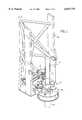
- FIG. 1is a partial view in perspective of a drill mast with the tool wrench and casing tong in place;
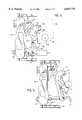
- FIG. 2is a top plan view of the tool wrench with the wrench arms engaged with a drill pipe shown in phantom lines;
- FIG. 3is a side view in elevation of the tool wrench of FIG. 2, again showing the drill pipe in phantom lines;
- FIG. 4is a view in cross-section through a drill pipe
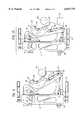
- FIGS. 5-11are top plan views showing the casing tong in various positions with respect to a drill pipe joint.
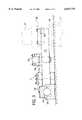
- FIG. 12is a hydraulic schematic view of a sequencing control mechanism for the casing tong.
- the automated casing tong 10generally is shown in conjunction with a mast 12 which is the subject of a commonly owned provisional patent application No. 60/020,856 of James P. Piper, Carl D. Gilmore, Kenneth W. Hammel, and Frank R. Szpek, Jr. for "Tubular Drill Mast" now U.S. Pat. No. 5,956,915.
- the casing tong 10is attached to the mast 12 by a tong support 14.
- two sections of drill pipe 16 and 17are connected by a drill pipe joint 18 with the lower drill pipe 17 held by a tool wrench 20.
- the casing tongincludes a tong arm 22 which is slidably supported by the support 24.
- a piston rod 27 of a first hydraulic cylinder 26is pivotally connected to one end of the arm 22 such as at pivot 29.
- the opposing end of the arm 22is also connected to a second hydraulic cylinder 31 such as by the rod 32 and the pivot point 34.
- Both cylinders 26 and 31are connected to the tong support 14 such as by the mountings 28 and 33, respectively.
- a jaw 36is pivotally connected to the arm 22 at a pivot point 42.
- the jaw 36is connected to a third hydraulic cylinder 38 by means of a pivot 40 with the opposite end of the cylinder 38 mounted on the tong arm 22 by the connection 41.
- a grip 44with die pair portions 43 such as through the pivot 45.
- Another pair of dies 46 forming a gripis mounted in a stationary manner on the tong arm 22. These dies 43 and 46 assist in gripping the pipe 16.
- the numeral 50indicates a customary pipe handling arm, and numeral 19 designates a deck bushing which can clear the casing tong 10 when in the stored position shown in FIG. 5.
- solenoid "a" of spool valve 52is energized. Hydraulic pressure of approximately 100 psi is then applied to the base end of cylinder 26 to extend the casing tong arm 22 into contact with the drill pipe 16. This is illustrated in FIG. 6. The pressure that is applied to the base end of cylinder 26 is also applied to the rod end of cylinder 31. As a constant hydraulic pressure of 1000 psi is applied to the base end of cylinder 31, force from cylinder 31 holds the pivot point 34 of the second end of the tong arm 22 in the end of a slot 35. Cylinder 31 will not retract at this time.
- solenoid "b" of spool valve 52is energized. Pressure is first applied to the rod end of cylinder 38 while cylinders 26 and 31 are kept from moving by pilot check valves 59.
- the tong jaw 44may be locked to the drill pipe 16 because of internal forces. If the tong jaw 44 is locked, hydraulic pressure applied to the rod end of cylinder 38 raises to 500 psi. Hydraulic oil then flows through sequence valve 57 to the rod end of cylinder 26. Pilot check valves 59 connected to the base end of cylinder 26 and the rod end of cylinder 31 open to allow movement in the cylinders. The resulting movement of the tong arm 22 unlocks the tong jaw 44. Pressure to the rod end of cylinder 38 drops below 500 psi and pilot check valves stop movement in cylinders 26 and 31. Normal retract then begins.
- cylinder 38retracts completely first. This is shown in FIG. 9. Pressure on the rod end of cylinder 38 then increases to 500 psi. Hydraulic oil then flows through sequence valve 57 to the rod end of cylinder 26. Pilot check valves open to allow retracting of cylinder 26 and extending of cylinder 31. This is illustrated in FIG. 10. A choke attached to the rod end of cylinder 31 controls flow from cylinder 31 to ensure that cylinder 26 retracts faster than cylinder 31 extends. This action causes the tong arm 22 to retract away from the drill pipe joint 18 without turning about the drill pipe joint. This feature reduces sliding between the tong dies 43 and 46 and the drill pipe 16 resulting in longer tong die life.
- the P and T designations in FIG. 12are for Pressure and Tank with the A and B designations indicating the ports of the spool valve 52.
- FIG. 11illustrates the tong assembly 10 in conjunction with a smaller pipe 21 in the same mole as shown in FIG. 8.
- the tool wrench 20is adapted to be mounted on the drill deck 60 of the mast 12 beneath the casing tong assembly 10.
- a pair of spaced pillow blocks 63 and 64 assembliesare attached to the deck 60 and mount a pivot rod 65.
- a support plate 66is rotatably mounted on the pivot rod 65.
- the support plate 66includes a projecting portion 70 that mounts a pair of spaced pivots 71 and 72.
- One end of a pair of wrench arms 73 and 74are mounted on the vertical pivots 71 and 72.
- Each arm 73 and 74includes an integral pawl 80 adjacent the free end of the arm.
- the pawls 80oppose each other.
- Each pawl 80is generally wedge-shaped with a stop surface 81 and with a curved top surface 82.
- Replaceable wear pads 83are mounted adjacent the pawls 80 and define a generally circular opening between the arms 73 and 74.
- a hydraulic cylinder 85is mounted at its base end in a clevis assembly 86 which is attached to one wrench arm 73.
- the piston rod 87 of the cylinder 85extends through a rod clevis assembly 88 attached to the other wrench arm 74.
- a spring mechanism 90 in the form of a compressible polymer bumperis held between a washer 91 mounted on the projecting end of the piston rod 87 and a washer 92 mounted against the rod clevis assembly 88.
- the tool wrenchis adapted to be used with a drill pipe 17 having a necked down portion 96 near its threaded top end 97.
- a shoulder 98is formed between the necked down portion 96 and the threaded end 97.
- the perimeter of the necked down portion 96includes a pair of wedge-shaped slots 100 disposed 180° apart. Each slot 100 has a portion 101 that lies along a diameter of the pipe and a second portion 102 that is transverse to the diameter and extends out to the perimeter of the necked down portion 96, as shown in FIG. 4.
- the wrench arms 73 and 74are retracted away from the drill pipe 17 by extending the hydraulic cylinder 85. When retracted, the wrench arms 73 and 74 will rest against stops 105 in the pivoting support 66. Constant force from the hydraulic cylinder 85 holds the wrench arms 73 and 74 against the stops 105 when the wrench arms 73 and 74 ire fully retracted.
- the drill pipe 17is hoisted until the necked down portion 96 is aligned to the level of the wrench arms 73 and 74.
- the wrench arms 73 and 74are then moved towards each other by retracting the hydraulic cylinder 85 until the pawls 80 of the wrench arms 73 and 74 contact the drill pipe 17.
- the pawls 80will not be aligned with the slots 100 when the pawls first contact the drill pipe 17.
- the force from the hydraulic cylinder 85will compress the spring mechanism 90, and constant force from the hydraulic cylinder 85 will hold the pawls 80 of the wrench arms 73 and 74 against the drill pipe 17.
- the drill pipe 17is rotated counterclockwise as viewed in FIG.
- the use of the tool wrench of the present inventionmakes it unnecessary for the drill operator to align flats or slots on the drill pipe to the tool wrench.
- the pawls 80will automatically engage the slots 100 upon rotation of the drill pipe 17.
- the slots 100allow 180° of counterclockwise pipe rotation and an unlimited ratcheting action with clockwise pipe rotation.
- the pivots 71 and 72 for the wrench arms 73 and 74are located such that the radial forces gripping the drill pipe will increase when torsional impact occurs between the pawls 80 and the rotating drill pipe slots 100. Because of this, the hydraulic cylinder 85 is not exposed to impact loads when the drill pipe joint is loosened.
- the pivot points 71 and 72are not symmetrically located relative to the drilling axis. One pivot is located using the smallest diameter drill pipe to be handled, and the other pivot is located using the largest diameter drill pipe to be handled.
- the preferred embodimentis employed with a triangular and tubular mast 12, it can also be employed with other mast configurations. Furthermore, the invention can be applied generally to loosening members that are joined by a threaded connection.
Landscapes
- Engineering & Computer Science (AREA)
- Life Sciences & Earth Sciences (AREA)
- Geology (AREA)
- Mining & Mineral Resources (AREA)
- Mechanical Engineering (AREA)
- Physics & Mathematics (AREA)
- Environmental & Geological Engineering (AREA)
- Fluid Mechanics (AREA)
- General Life Sciences & Earth Sciences (AREA)
- Geochemistry & Mineralogy (AREA)
- Earth Drilling (AREA)
Abstract
Description
Claims (14)
Priority Applications (1)
| Application Number | Priority Date | Filing Date | Title |
|---|---|---|---|
| US09/358,216US6047775A (en) | 1996-06-27 | 1999-07-21 | Blast hole drill pipe gripping mechanism |
Applications Claiming Priority (3)
| Application Number | Priority Date | Filing Date | Title |
|---|---|---|---|
| US2066296P | 1996-06-27 | 1996-06-27 | |
| US08/879,930US5931231A (en) | 1996-06-27 | 1997-06-17 | Blast hole drill pipe gripping mechanism |
| US09/358,216US6047775A (en) | 1996-06-27 | 1999-07-21 | Blast hole drill pipe gripping mechanism |
Related Parent Applications (1)
| Application Number | Title | Priority Date | Filing Date |
|---|---|---|---|
| US08/879,930DivisionUS5931231A (en) | 1996-06-27 | 1997-06-17 | Blast hole drill pipe gripping mechanism |
Publications (1)
| Publication Number | Publication Date |
|---|---|
| US6047775Atrue US6047775A (en) | 2000-04-11 |
Family
ID=27658056
Family Applications (1)
| Application Number | Title | Priority Date | Filing Date |
|---|---|---|---|
| US09/358,216Expired - LifetimeUS6047775A (en) | 1996-06-27 | 1999-07-21 | Blast hole drill pipe gripping mechanism |
Country Status (2)
| Country | Link |
|---|---|
| US (1) | US6047775A (en) |
| ZA (1) | ZA975750B (en) |
Cited By (23)
| Publication number | Priority date | Publication date | Assignee | Title |
|---|---|---|---|---|
| US20020157823A1 (en)* | 1999-11-26 | 2002-10-31 | Bernd-Georg Pietras | Wrenching tong |
| US20030075023A1 (en)* | 2000-02-25 | 2003-04-24 | Dicky Robichaux | Apparatus and method relating to tongs, continous circulation and to safety slips |
| US20040237726A1 (en)* | 2002-02-12 | 2004-12-02 | Schulze Beckinghausen Joerg E. | Tong |
| GB2406867A (en)* | 2003-10-08 | 2005-04-13 | Weatherford Lamb | Tong assembly |
| US20050076744A1 (en)* | 2003-10-08 | 2005-04-14 | Weatherford/Lamb, Inc. | Apparatus and methods for connecting tubulars |
| US7090254B1 (en) | 1999-04-13 | 2006-08-15 | Bernd-Georg Pietras | Apparatus and method aligning tubulars |
| US20080060481A1 (en)* | 2006-09-08 | 2008-03-13 | Canrig Drilling Technology Ltd. | Oilfield tubular spin-in and spin-out detection for making-up and breaking-out tubular strings |
| US7506564B2 (en) | 2002-02-12 | 2009-03-24 | Weatherford/Lamb, Inc. | Gripping system for a tong |
| US20090205442A1 (en)* | 2006-08-24 | 2009-08-20 | Canrig Drilling Technology Ltd. | Oilfield tubular torque wrench |
| US20090211405A1 (en)* | 2006-08-24 | 2009-08-27 | Canrig Drilling Technology Ltd. | Oilfield tubular torque wrench |
| US20090217788A1 (en)* | 2006-08-25 | 2009-09-03 | Canrig Drilling Technology Ltd. | Methods and apparatus for automated oilfield torque wrench set-up to make-up and break-out tubular strings |
| US20100270082A1 (en)* | 2009-04-24 | 2010-10-28 | Terex Corporation | Rotary blasthole drilling rig flexible jaw pipe positioner |
| WO2011143691A1 (en) | 2010-05-19 | 2011-11-24 | Burt Consolidated Engineering Pty Ltd | Breakout tool |
| WO2013036135A3 (en)* | 2011-09-09 | 2013-09-12 | National Oilwell Varco Norway As | Control equipment for a torque device for oil field use and method for operation of same |
| US20130239754A1 (en)* | 2012-03-16 | 2013-09-19 | Francis Torq/Lite, Inc. | Squeezing head torque tool |
| US20130306378A1 (en)* | 2012-05-16 | 2013-11-21 | Atlas Copco North America, Llc | Rod support system |
| US8746111B2 (en) | 2010-04-15 | 2014-06-10 | Astec Industries, Inc. | Floating wrench assembly for drill rig |
| US20150231768A1 (en)* | 2014-02-19 | 2015-08-20 | Torq/Lite, Llc | Squeezing clamp hammer union torque tool |
| CN106217300A (en)* | 2016-08-18 | 2016-12-14 | 中国航空工业集团公司沈阳发动机设计研究所 | A kind of retainer erecting device |
| US20170328150A1 (en)* | 2016-05-12 | 2017-11-16 | David L. Sipos | Integrated Flush-Mount Spider and Power-Tong Apparatus and Method of Use |
| GR1009556B (en)* | 2018-01-25 | 2019-07-02 | Νικολαος Σωτηριου Βρουσιας | Screwing and unscrewing mechanism for drilling tubes of any type |
| US20220009059A1 (en)* | 2020-07-13 | 2022-01-13 | Milwaukee Electric Tool Corporation | Pipe fitting tool |
| WO2023020341A1 (en)* | 2021-08-16 | 2023-02-23 | 安百拓(南京)建筑矿山设备有限公司 | Rod dismounting pliers |
Citations (15)
| Publication number | Priority date | Publication date | Assignee | Title |
|---|---|---|---|---|
| US2871743A (en)* | 1958-02-10 | 1959-02-03 | Benjamin F Kelley | Hydraulic pipe tonging device |
| US3177944A (en)* | 1959-06-02 | 1965-04-13 | Dowty Rotol Ltd | Racking mechanism for earth boring equipment |
| US3194313A (en)* | 1956-09-24 | 1965-07-13 | F N R D Ltd | Earth drilling rigs |
| US3316783A (en)* | 1965-02-19 | 1967-05-02 | Wilson Mfg Co | Pipe tongs |
| US3500708A (en)* | 1967-05-01 | 1970-03-17 | Wilson John H | Automated pipe tongs |
| US3506075A (en)* | 1966-10-07 | 1970-04-14 | Atlas Copco Ab | Drill string element transfer mechanism |
| US3702640A (en)* | 1970-04-13 | 1972-11-14 | Petroles Cie Francaise | Tipping girder for the transfer of rods or tubular elements |
| US3803453A (en)* | 1972-07-21 | 1974-04-09 | Du Pont | Synthetic filament having antistatic properties |
| US3803953A (en)* | 1972-03-01 | 1974-04-16 | Byron Jackson Inc | Orienting apparatus for threaded well pipe |
| US3843945A (en)* | 1973-06-14 | 1974-10-22 | Northrop Corp | Temperature compensation of electromagnetic device |
| US4082017A (en)* | 1975-01-07 | 1978-04-04 | Eckel Manufacturing Co. | Power operated drill pipe tongs |
| US4660634A (en)* | 1985-06-19 | 1987-04-28 | North Houston Machine, Inc. | Automatic drill pipe breakout |
| US4843945A (en)* | 1987-03-09 | 1989-07-04 | National-Oilwell | Apparatus for making and breaking threaded well pipe connections |
| US4867236A (en)* | 1987-10-09 | 1989-09-19 | W-N Apache Corporation | Compact casing tongs for use on top head drive earth drilling machine |
| US5653297A (en)* | 1995-04-14 | 1997-08-05 | Harnischfeger Corporation | Blasthole drill with improved automatic breakout wrench |
- 1997
- 1997-06-27ZAZA9705750Apatent/ZA975750B/enunknown
- 1999
- 1999-07-21USUS09/358,216patent/US6047775A/ennot_activeExpired - Lifetime
Patent Citations (15)
| Publication number | Priority date | Publication date | Assignee | Title |
|---|---|---|---|---|
| US3194313A (en)* | 1956-09-24 | 1965-07-13 | F N R D Ltd | Earth drilling rigs |
| US2871743A (en)* | 1958-02-10 | 1959-02-03 | Benjamin F Kelley | Hydraulic pipe tonging device |
| US3177944A (en)* | 1959-06-02 | 1965-04-13 | Dowty Rotol Ltd | Racking mechanism for earth boring equipment |
| US3316783A (en)* | 1965-02-19 | 1967-05-02 | Wilson Mfg Co | Pipe tongs |
| US3506075A (en)* | 1966-10-07 | 1970-04-14 | Atlas Copco Ab | Drill string element transfer mechanism |
| US3500708A (en)* | 1967-05-01 | 1970-03-17 | Wilson John H | Automated pipe tongs |
| US3702640A (en)* | 1970-04-13 | 1972-11-14 | Petroles Cie Francaise | Tipping girder for the transfer of rods or tubular elements |
| US3803953A (en)* | 1972-03-01 | 1974-04-16 | Byron Jackson Inc | Orienting apparatus for threaded well pipe |
| US3803453A (en)* | 1972-07-21 | 1974-04-09 | Du Pont | Synthetic filament having antistatic properties |
| US3843945A (en)* | 1973-06-14 | 1974-10-22 | Northrop Corp | Temperature compensation of electromagnetic device |
| US4082017A (en)* | 1975-01-07 | 1978-04-04 | Eckel Manufacturing Co. | Power operated drill pipe tongs |
| US4660634A (en)* | 1985-06-19 | 1987-04-28 | North Houston Machine, Inc. | Automatic drill pipe breakout |
| US4843945A (en)* | 1987-03-09 | 1989-07-04 | National-Oilwell | Apparatus for making and breaking threaded well pipe connections |
| US4867236A (en)* | 1987-10-09 | 1989-09-19 | W-N Apache Corporation | Compact casing tongs for use on top head drive earth drilling machine |
| US5653297A (en)* | 1995-04-14 | 1997-08-05 | Harnischfeger Corporation | Blasthole drill with improved automatic breakout wrench |
Non-Patent Citations (4)
| Title |
|---|
| Applicant s Exhibit A; Bucyrus Erie Company parts lists pp. 12 4 (1 through 4), 12 5 (and 2), 12 6 (1 and 2), 12 7 (1 and 2), and operating instructions 45 591 (two pages), dated between Sep. 1983 and Jun. 1989.* |
| Applicant s Exhibit B; Bucyrus Erie Company parts lists (plate VM1468, two pages) and operating instructions pp. 4 15 through 4 27, dated Feb. 1995.* |
| Applicant's Exhibit A; Bucyrus-Erie Company parts lists pp. 12-4 (1 through 4), 12-5 (and 2), 12-6 (1 and 2), 12-7 (1 and 2), and operating instructions 45 591 (two pages), dated between Sep. 1983 and Jun. 1989. |
| Applicant's Exhibit B; Bucyrus-Erie Company parts lists (plate VM1468, two pages) and operating instructions pp. 4-15 through 4-27, dated Feb. 1995. |
Cited By (59)
| Publication number | Priority date | Publication date | Assignee | Title |
|---|---|---|---|---|
| US7090254B1 (en) | 1999-04-13 | 2006-08-15 | Bernd-Georg Pietras | Apparatus and method aligning tubulars |
| US7861618B2 (en) | 1999-11-26 | 2011-01-04 | Weatherford/Lamb, Inc. | Wrenching tong |
| US20020157823A1 (en)* | 1999-11-26 | 2002-10-31 | Bernd-Georg Pietras | Wrenching tong |
| US7028585B2 (en) | 1999-11-26 | 2006-04-18 | Weatherford/Lamb, Inc. | Wrenching tong |
| US20060179980A1 (en)* | 1999-11-26 | 2006-08-17 | Weatherford/Lamb, Inc. | Wrenching tong |
| US20030075023A1 (en)* | 2000-02-25 | 2003-04-24 | Dicky Robichaux | Apparatus and method relating to tongs, continous circulation and to safety slips |
| US7028586B2 (en) | 2000-02-25 | 2006-04-18 | Weatherford/Lamb, Inc. | Apparatus and method relating to tongs, continous circulation and to safety slips |
| US7281451B2 (en) | 2002-02-12 | 2007-10-16 | Weatherford/Lamb, Inc. | Tong |
| US20040237726A1 (en)* | 2002-02-12 | 2004-12-02 | Schulze Beckinghausen Joerg E. | Tong |
| US7506564B2 (en) | 2002-02-12 | 2009-03-24 | Weatherford/Lamb, Inc. | Gripping system for a tong |
| GB2406867B (en)* | 2003-10-08 | 2006-11-22 | Weatherford Lamb | Tubular handling apparatus |
| US20050076744A1 (en)* | 2003-10-08 | 2005-04-14 | Weatherford/Lamb, Inc. | Apparatus and methods for connecting tubulars |
| US20050077743A1 (en)* | 2003-10-08 | 2005-04-14 | Bernd-Georg Pietras | Tong assembly |
| US7707914B2 (en) | 2003-10-08 | 2010-05-04 | Weatherford/Lamb, Inc. | Apparatus and methods for connecting tubulars |
| GB2406867A (en)* | 2003-10-08 | 2005-04-13 | Weatherford Lamb | Tong assembly |
| US7958787B2 (en) | 2006-08-24 | 2011-06-14 | Canrig Drilling Technology Ltd. | Oilfield tubular torque wrench |
| US20090205442A1 (en)* | 2006-08-24 | 2009-08-20 | Canrig Drilling Technology Ltd. | Oilfield tubular torque wrench |
| US20090211405A1 (en)* | 2006-08-24 | 2009-08-27 | Canrig Drilling Technology Ltd. | Oilfield tubular torque wrench |
| US8042432B2 (en) | 2006-08-24 | 2011-10-25 | Canrig Drilling Technology Ltd. | Oilfield tubular torque wrench |
| US20090217788A1 (en)* | 2006-08-25 | 2009-09-03 | Canrig Drilling Technology Ltd. | Methods and apparatus for automated oilfield torque wrench set-up to make-up and break-out tubular strings |
| US9097070B2 (en) | 2006-08-25 | 2015-08-04 | Canrig Drilling Technology Ltd. | Apparatus for automated oilfield torque wrench set-up to make-up and break-out tubular strings |
| US8490520B2 (en) | 2006-09-08 | 2013-07-23 | Canrig Drilling Technology Ltd. | Oilfield tubular spin-in and spin-out detection for making-up and breaking-out tubular strings |
| US20080060481A1 (en)* | 2006-09-08 | 2008-03-13 | Canrig Drilling Technology Ltd. | Oilfield tubular spin-in and spin-out detection for making-up and breaking-out tubular strings |
| US9404324B2 (en) | 2006-09-08 | 2016-08-02 | Canrig Drilling Technology Ltd. | Oilfield tubular spin-in and spin-out detection for making-up and breaking-out tubular strings |
| US8074537B2 (en) | 2006-09-08 | 2011-12-13 | Canrig Drilling Technology Ltd. | Oilfield tubular spin-in and spin-out detection for making-up and breaking-out tubular strings |
| US10329857B2 (en) | 2006-09-08 | 2019-06-25 | Nabors Drilling Technologies Usa, Inc. | Oilfield tubular spin-in and spin-out detection for making-up and breaking-out tubular strings |
| US8151903B2 (en)* | 2009-04-24 | 2012-04-10 | Caterpillar Global Mining Llc | Rotary blasthole drilling rig flexible jaw pipe positioner |
| US20100270082A1 (en)* | 2009-04-24 | 2010-10-28 | Terex Corporation | Rotary blasthole drilling rig flexible jaw pipe positioner |
| CN102428247A (en)* | 2009-04-24 | 2012-04-25 | 比塞洛斯采矿设备公司 | Rotary blasthole drilling rig flexible jaw pipe positioner |
| WO2010124194A3 (en)* | 2009-04-24 | 2011-03-03 | Bucyrus Mining Equipment, Inc. | Rotary blasthole drilling rig flexible jaw pipe positioner |
| US8746111B2 (en) | 2010-04-15 | 2014-06-10 | Astec Industries, Inc. | Floating wrench assembly for drill rig |
| EP2572071B1 (en)* | 2010-05-19 | 2019-10-30 | Metzke Pty Ltd | Breakout tool |
| KR20130124164A (en)* | 2010-05-19 | 2013-11-13 | 메츠케 피티와이 엘티디 | Breakout tool |
| WO2011143691A1 (en) | 2010-05-19 | 2011-11-24 | Burt Consolidated Engineering Pty Ltd | Breakout tool |
| US9181766B2 (en) | 2010-05-19 | 2015-11-10 | Metzke Pty. Ltd. | Breakout tool |
| AU2011256120B2 (en)* | 2010-05-19 | 2014-10-23 | Metzke Pty Ltd | Breakout tool |
| WO2013036135A3 (en)* | 2011-09-09 | 2013-09-12 | National Oilwell Varco Norway As | Control equipment for a torque device for oil field use and method for operation of same |
| WO2013036143A3 (en)* | 2011-09-09 | 2013-10-10 | National Oilwell Varco Norway As | A torque device for oil field use and method of operation for same |
| US20150107420A1 (en)* | 2011-09-09 | 2015-04-23 | National Oilwell Varco Norway As | Torque Device for Oil Field Use and Method of Operation for Same |
| KR20140077905A (en)* | 2011-09-09 | 2014-06-24 | 내쇼날 오일웰 파르코 노르웨이 에이에스 | A torque device for oil field use and method of operation for same |
| US10550651B2 (en)* | 2011-09-09 | 2020-02-04 | National Oilwell Varco Norway As | Torque device for oil field use and method of operation for same |
| US11492857B2 (en) | 2011-09-09 | 2022-11-08 | National Oilwell Varco Norway As | Torque device for oil field use and method of operation for same |
| US20130239754A1 (en)* | 2012-03-16 | 2013-09-19 | Francis Torq/Lite, Inc. | Squeezing head torque tool |
| US20130306378A1 (en)* | 2012-05-16 | 2013-11-21 | Atlas Copco North America, Llc | Rod support system |
| US9074424B2 (en)* | 2012-05-16 | 2015-07-07 | Atlas Copco Drilling Solutions, Llc | Rod support system |
| US9782876B2 (en)* | 2014-02-19 | 2017-10-10 | Torq/Lite, Llc | Squeezing clamp hammer union torque tool |
| US11167397B1 (en)* | 2014-02-19 | 2021-11-09 | Torq/Lite, Llc | Squeezing clamp hammer union torque tool |
| US20180104799A1 (en)* | 2014-02-19 | 2018-04-19 | Torq/Lite, Llc | Squeezing clamp hammer union torque tool |
| US11618137B1 (en)* | 2014-02-19 | 2023-04-04 | Torq/Lite, Llc | Squeezing clamp hammer union torque tool |
| US20150231768A1 (en)* | 2014-02-19 | 2015-08-20 | Torq/Lite, Llc | Squeezing clamp hammer union torque tool |
| US10518393B2 (en)* | 2014-02-19 | 2019-12-31 | Torq/Lite, Llc | Squeezing clamp hammer union torque tool |
| US10619429B2 (en)* | 2016-05-12 | 2020-04-14 | Odfjell Well Services Norway As | Integrated flush-mount spider and power-tong apparatus and method of use |
| US20170328150A1 (en)* | 2016-05-12 | 2017-11-16 | David L. Sipos | Integrated Flush-Mount Spider and Power-Tong Apparatus and Method of Use |
| CN106217300B (en)* | 2016-08-18 | 2018-07-13 | 中国航空工业集团公司沈阳发动机设计研究所 | A kind of retainer mounting device |
| CN106217300A (en)* | 2016-08-18 | 2016-12-14 | 中国航空工业集团公司沈阳发动机设计研究所 | A kind of retainer erecting device |
| GR1009556B (en)* | 2018-01-25 | 2019-07-02 | Νικολαος Σωτηριου Βρουσιας | Screwing and unscrewing mechanism for drilling tubes of any type |
| US20220009059A1 (en)* | 2020-07-13 | 2022-01-13 | Milwaukee Electric Tool Corporation | Pipe fitting tool |
| US12226879B2 (en)* | 2020-07-13 | 2025-02-18 | Milwaukee Electric Tool Corporation | Pipe fitting tool |
| WO2023020341A1 (en)* | 2021-08-16 | 2023-02-23 | 安百拓(南京)建筑矿山设备有限公司 | Rod dismounting pliers |
Also Published As
| Publication number | Publication date |
|---|---|
| ZA975750B (en) | 1998-01-26 |
Similar Documents
| Publication | Publication Date | Title |
|---|---|---|
| US5931231A (en) | Blast hole drill pipe gripping mechanism | |
| US6047775A (en) | Blast hole drill pipe gripping mechanism | |
| CA1071183A (en) | Drill pipe handling mechanism | |
| EP0578657B1 (en) | Power tong for releasing tight joints | |
| CA2306936C (en) | Apparatus for unscrewing drill pipe sections | |
| US4449592A (en) | Automatic drill string section changer | |
| US4304433A (en) | Pipe gripping head | |
| US4194419A (en) | Drill pipe handling mechanism | |
| US7281451B2 (en) | Tong | |
| US4519576A (en) | Oil well safety valve for use with drill pipe | |
| US3832918A (en) | Breakout wrench | |
| US20050076744A1 (en) | Apparatus and methods for connecting tubulars | |
| JPS6144541A (en) | Back-up-tongue and method of ensuring no-revolution of tubular member and power tongue | |
| GB2151278A (en) | Apparatus for injecting coil tubing into a well and method of servicing a well | |
| NO337699B1 (en) | Load ring for lifting with pipe claw, of casing without thickening | |
| EP0629260A1 (en) | Automatic torque wrenching machine | |
| US4603464A (en) | Stand jumping and stabbing guide device and method | |
| EP0984217B1 (en) | Apparatus for plugging a pipe | |
| US20150361738A1 (en) | Large diameter tubular lifting apparatuses and methods | |
| US3441323A (en) | Centralizer | |
| CA2259082C (en) | Power tong with improved door mechanism | |
| CA2440176C (en) | Blast hole drill pipe gripping mechanism | |
| AU737131B2 (en) | Blast hole drill pipe gripping mechanism | |
| US6279426B1 (en) | Power tong with improved door latch | |
| US5388652A (en) | Apparatus on a drilling tower for gripping a drill casing |
Legal Events
| Date | Code | Title | Description |
|---|---|---|---|
| STCF | Information on status: patent grant | Free format text:PATENTED CASE | |
| FPAY | Fee payment | Year of fee payment:4 | |
| AS | Assignment | Owner name:GMAC COMMERCIAL FINANCE LLC, AS AGENT, NEW YORK Free format text:SECURITY INTEREST;ASSIGNOR:BUCYRUS INTERNATIONAL, INC.;REEL/FRAME:015642/0537 Effective date:20040728 | |
| AS | Assignment | Owner name:BUCYRUS INTERNATIONAL, INC., WISCONSIN Free format text:RELEASE OF SECURITY INTEREST IN PATENT COLLATERAL (REEL/FRAME NO. 015642/0537);ASSIGNOR:GMAC COMMERCIAL FINANCE, LLC;REEL/FRAME:019254/0196 Effective date:20070504 | |
| AS | Assignment | Owner name:LEHMAN COMMERCIAL PAPER INC., AS ADMINISTRATIVE AG Free format text:INTELLECTUAL PROPERTY SECURITY AGREEMENT;ASSIGNOR:BUCYRUS INTERNATIONAL INC.;REEL/FRAME:019260/0457 Effective date:20070504 | |
| FPAY | Fee payment | Year of fee payment:8 | |
| AS | Assignment | Owner name:JPMORGAN CHASE BANK, N.A., ILLINOIS Free format text:ASSIGNMENT AND ASSUMPTION REGARDING REEL/FRAME NOS. 019260/0457 AND 019541/0048;ASSIGNOR:LEHMAN COMMERCIAL PAPER INC.;REEL/FRAME:022092/0031 Effective date:20081216 | |
| FEPP | Fee payment procedure | Free format text:PAYOR NUMBER ASSIGNED (ORIGINAL EVENT CODE: ASPN); ENTITY STATUS OF PATENT OWNER: LARGE ENTITY Free format text:PAYER NUMBER DE-ASSIGNED (ORIGINAL EVENT CODE: RMPN); ENTITY STATUS OF PATENT OWNER: LARGE ENTITY | |
| AS | Assignment | Owner name:BUCYRUS INTERNATIONAL, INC., WISCONSIN Free format text:RELEASE BY SECURED PARTY;ASSIGNOR:JPMORGAN CHASE BANK, N.A.;REEL/FRAME:026585/0001 Effective date:20110708 | |
| FPAY | Fee payment | Year of fee payment:12 | |
| AS | Assignment | Owner name:CATERPILLAR GLOBAL MINING LLC, WISCONSIN Free format text:CHANGE OF NAME;ASSIGNOR:BUCYRUS INTERNATIONAL, INC.;REEL/FRAME:036540/0980 Effective date:20110929 |