US6047700A - Systems and methods for electrosurgical removal of calcified deposits - Google Patents
Systems and methods for electrosurgical removal of calcified depositsDownload PDFInfo
- Publication number
- US6047700A US6047700AUS09/083,533US8353398AUS6047700AUS 6047700 AUS6047700 AUS 6047700AUS 8353398 AUS8353398 AUS 8353398AUS 6047700 AUS6047700 AUS 6047700A
- Authority
- US
- United States
- Prior art keywords
- electrode
- tissue
- electrode terminal
- fluid
- heart valve
- Prior art date
- Legal status (The legal status is an assumption and is not a legal conclusion. Google has not performed a legal analysis and makes no representation as to the accuracy of the status listed.)
- Expired - Lifetime
Links
- 238000000034methodMethods0.000titleclaimsabstractdescription116
- 239000000463materialSubstances0.000claimsabstractdescription38
- 210000003709heart valveAnatomy0.000claimsabstractdescription26
- 230000006378damageEffects0.000claimsabstractdescription15
- 239000012530fluidSubstances0.000claimsdescription160
- 210000001519tissueAnatomy0.000claimsdescription158
- FAPWRFPIFSIZLT-UHFFFAOYSA-MSodium chlorideChemical compound[Na+].[Cl-]FAPWRFPIFSIZLT-UHFFFAOYSA-M0.000claimsdescription24
- 210000005003heart tissueAnatomy0.000claimsdescription19
- 238000010494dissociation reactionMethods0.000claimsdescription15
- 230000005593dissociationsEffects0.000claimsdescription15
- 239000002245particleSubstances0.000claimsdescription11
- 239000012634fragmentSubstances0.000claimsdescription10
- 230000008016vaporizationEffects0.000claimsdescription7
- 230000015572biosynthetic processEffects0.000claimsdescription4
- 238000011065in-situ storageMethods0.000claimsdescription4
- 231100000435percutaneous penetrationToxicity0.000claimsdescription2
- 239000000523sampleSubstances0.000abstractdescription75
- 210000004177elastic tissueAnatomy0.000abstractdescription6
- 201000010260leiomyomaDiseases0.000abstractdescription5
- 230000036961partial effectEffects0.000abstractdescription3
- 238000002679ablationMethods0.000description36
- 239000010410layerSubstances0.000description19
- 230000015271coagulationEffects0.000description17
- 238000005345coagulationMethods0.000description17
- 239000008280bloodSubstances0.000description14
- 210000004369bloodAnatomy0.000description14
- 208000004434CalcinosisDiseases0.000description12
- 229910045601alloyInorganic materials0.000description12
- 239000000956alloySubstances0.000description12
- 238000001356surgical procedureMethods0.000description12
- 230000005684electric fieldEffects0.000description11
- 230000009467reductionEffects0.000description11
- 210000001765aortic valveAnatomy0.000description10
- 238000005520cutting processMethods0.000description10
- 238000010438heat treatmentMethods0.000description10
- 230000008439repair processEffects0.000description10
- 230000000694effectsEffects0.000description9
- 239000000919ceramicSubstances0.000description8
- 230000000670limiting effectEffects0.000description8
- 239000011159matrix materialSubstances0.000description8
- 230000017074necrotic cell deathEffects0.000description8
- BASFCYQUMIYNBI-UHFFFAOYSA-NplatinumChemical compound[Pt]BASFCYQUMIYNBI-UHFFFAOYSA-N0.000description8
- 230000008602contractionEffects0.000description7
- 230000008878couplingEffects0.000description7
- 238000010168coupling processMethods0.000description7
- 238000005859coupling reactionMethods0.000description7
- 238000001804debridementMethods0.000description7
- 229910052751metalInorganic materials0.000description7
- PXHVJJICTQNCMI-UHFFFAOYSA-NNickelChemical compound[Ni]PXHVJJICTQNCMI-UHFFFAOYSA-N0.000description6
- 210000004204blood vesselAnatomy0.000description6
- 239000007789gasSubstances0.000description6
- 239000011521glassSubstances0.000description6
- 239000007788liquidSubstances0.000description6
- 239000002184metalSubstances0.000description6
- 210000004115mitral valveAnatomy0.000description6
- 210000005036nerveAnatomy0.000description6
- 239000004033plasticSubstances0.000description6
- 229920003023plasticPolymers0.000description6
- 230000008569processEffects0.000description6
- 239000011780sodium chlorideSubstances0.000description6
- RTAQQCXQSZGOHL-UHFFFAOYSA-NTitaniumChemical compound[Ti]RTAQQCXQSZGOHL-UHFFFAOYSA-N0.000description5
- 239000003990capacitorSubstances0.000description5
- 239000004020conductorSubstances0.000description5
- 238000013461designMethods0.000description5
- 230000004907fluxEffects0.000description5
- 230000023597hemostasisEffects0.000description5
- 239000010936titaniumSubstances0.000description5
- 229910052719titaniumInorganic materials0.000description5
- 238000009834vaporizationMethods0.000description5
- XKRFYHLGVUSROY-UHFFFAOYSA-NArgonChemical compound[Ar]XKRFYHLGVUSROY-UHFFFAOYSA-N0.000description4
- OYPRJOBELJOOCE-UHFFFAOYSA-NCalciumChemical compound[Ca]OYPRJOBELJOOCE-UHFFFAOYSA-N0.000description4
- 206010067171RegurgitationDiseases0.000description4
- 230000002308calcificationEffects0.000description4
- 230000015556catabolic processEffects0.000description4
- 238000000576coating methodMethods0.000description4
- 229910052697platinumInorganic materials0.000description4
- 230000002829reductive effectEffects0.000description4
- 230000000638stimulationEffects0.000description4
- 210000005166vasculatureAnatomy0.000description4
- 102000008186CollagenHuman genes0.000description3
- 108010035532CollagenProteins0.000description3
- ZOKXTWBITQBERF-UHFFFAOYSA-NMolybdenumChemical compound[Mo]ZOKXTWBITQBERF-UHFFFAOYSA-N0.000description3
- 208000031481Pathologic ConstrictionDiseases0.000description3
- 239000000853adhesiveSubstances0.000description3
- 230000001070adhesive effectEffects0.000description3
- PNEYBMLMFCGWSK-UHFFFAOYSA-Naluminium oxideInorganic materials[O-2].[O-2].[O-2].[Al+3].[Al+3]PNEYBMLMFCGWSK-UHFFFAOYSA-N0.000description3
- 230000017531blood circulationEffects0.000description3
- 229910052791calciumInorganic materials0.000description3
- 239000011575calciumSubstances0.000description3
- 230000000747cardiac effectEffects0.000description3
- 210000004027cellAnatomy0.000description3
- 229920001436collagenPolymers0.000description3
- 210000002808connective tissueAnatomy0.000description3
- 230000006870functionEffects0.000description3
- 230000003601intercostal effectEffects0.000description3
- 210000005240left ventricleAnatomy0.000description3
- 229910052750molybdenumInorganic materials0.000description3
- 239000011733molybdenumSubstances0.000description3
- 210000003928nasal cavityAnatomy0.000description3
- 229910052759nickelInorganic materials0.000description3
- 238000007789sealingMethods0.000description3
- 239000003566sealing materialSubstances0.000description3
- 230000036262stenosisEffects0.000description3
- 208000037804stenosisDiseases0.000description3
- 210000000115thoracic cavityAnatomy0.000description3
- 230000000451tissue damageEffects0.000description3
- 231100000827tissue damageToxicity0.000description3
- WFKWXMTUELFFGS-UHFFFAOYSA-NtungstenChemical compound[W]WFKWXMTUELFFGS-UHFFFAOYSA-N0.000description3
- 229910052721tungstenInorganic materials0.000description3
- 239000010937tungstenSubstances0.000description3
- 210000001186vagus nerveAnatomy0.000description3
- 240000005020Acaciella glaucaSpecies0.000description2
- IJGRMHOSHXDMSA-UHFFFAOYSA-NAtomic nitrogenChemical compoundN#NIJGRMHOSHXDMSA-UHFFFAOYSA-N0.000description2
- OKTJSMMVPCPJKN-UHFFFAOYSA-NCarbonChemical compound[C]OKTJSMMVPCPJKN-UHFFFAOYSA-N0.000description2
- CURLTUGMZLYLDI-UHFFFAOYSA-NCarbon dioxideChemical compoundO=C=OCURLTUGMZLYLDI-UHFFFAOYSA-N0.000description2
- 239000004593EpoxySubstances0.000description2
- 208000007536ThrombosisDiseases0.000description2
- MCMNRKCIXSYSNV-UHFFFAOYSA-NZirconium dioxideChemical compoundO=[Zr]=OMCMNRKCIXSYSNV-UHFFFAOYSA-N0.000description2
- 230000002159abnormal effectEffects0.000description2
- 230000001464adherent effectEffects0.000description2
- 230000010100anticoagulationEffects0.000description2
- 206010002906aortic stenosisDiseases0.000description2
- 201000002064aortic valve insufficiencyDiseases0.000description2
- 229910052786argonInorganic materials0.000description2
- 238000003491arrayMethods0.000description2
- QVGXLLKOCUKJST-UHFFFAOYSA-Natomic oxygenChemical compound[O]QVGXLLKOCUKJST-UHFFFAOYSA-N0.000description2
- 238000010009beatingMethods0.000description2
- 230000008901benefitEffects0.000description2
- 230000000740bleeding effectEffects0.000description2
- 210000000988bone and boneAnatomy0.000description2
- 229910052799carbonInorganic materials0.000description2
- 210000000038chestAnatomy0.000description2
- 239000011248coating agentSubstances0.000description2
- 230000007423decreaseEffects0.000description2
- 238000006731degradation reactionMethods0.000description2
- 238000011161developmentMethods0.000description2
- 230000018109developmental processEffects0.000description2
- 239000003792electrolyteSubstances0.000description2
- 239000000835fiberSubstances0.000description2
- 230000003176fibrotic effectEffects0.000description2
- 238000013467fragmentationMethods0.000description2
- 238000006062fragmentation reactionMethods0.000description2
- 230000005484gravityEffects0.000description2
- 230000035876healingEffects0.000description2
- 239000001257hydrogenSubstances0.000description2
- 229910052739hydrogenInorganic materials0.000description2
- 238000003384imaging methodMethods0.000description2
- 238000002608intravascular ultrasoundMethods0.000description2
- 210000004072lungAnatomy0.000description2
- 238000004519manufacturing processMethods0.000description2
- 230000007246mechanismEffects0.000description2
- 230000008018meltingEffects0.000description2
- 238000002844meltingMethods0.000description2
- 150000002739metalsChemical class0.000description2
- VNWKTOKETHGBQD-UHFFFAOYSA-NmethaneChemical compoundCVNWKTOKETHGBQD-UHFFFAOYSA-N0.000description2
- 239000001301oxygenSubstances0.000description2
- 229910052760oxygenInorganic materials0.000description2
- 230000035515penetrationEffects0.000description2
- -1polytetrafluoroethylenePolymers0.000description2
- 229920001343polytetrafluoroethylenePolymers0.000description2
- 239000004810polytetrafluoroethyleneSubstances0.000description2
- 238000004321preservationMethods0.000description2
- 230000002685pulmonary effectEffects0.000description2
- 238000005086pumpingMethods0.000description2
- 235000003499redwoodNutrition0.000description2
- 238000007493shaping processMethods0.000description2
- 210000004872soft tissueAnatomy0.000description2
- 229910001220stainless steelInorganic materials0.000description2
- 239000010935stainless steelSubstances0.000description2
- 230000002966stenotic effectEffects0.000description2
- 239000002344surface layerSubstances0.000description2
- 210000002435tendonAnatomy0.000description2
- 210000000591tricuspid valveAnatomy0.000description2
- 238000002604ultrasonographyMethods0.000description2
- 230000002861ventricularEffects0.000description2
- 238000012800visualizationMethods0.000description2
- 206010002915Aortic valve incompetenceDiseases0.000description1
- RYGMFSIKBFXOCR-UHFFFAOYSA-NCopperChemical compound[Cu]RYGMFSIKBFXOCR-UHFFFAOYSA-N0.000description1
- 208000005189EmbolismDiseases0.000description1
- 206010014666Endocarditis bacterialDiseases0.000description1
- 206010016654FibrosisDiseases0.000description1
- UFHFLCQGNIYNRP-UHFFFAOYSA-NHydrogenChemical compound[H][H]UFHFLCQGNIYNRP-UHFFFAOYSA-N0.000description1
- DGAQECJNVWCQMB-PUAWFVPOSA-MIlexoside XXIXChemical compoundC[C@@H]1CC[C@@]2(CC[C@@]3(C(=CC[C@H]4[C@]3(CC[C@@H]5[C@@]4(CC[C@@H](C5(C)C)OS(=O)(=O)[O-])C)C)[C@@H]2[C@]1(C)O)C)C(=O)O[C@H]6[C@@H]([C@H]([C@@H]([C@H](O6)CO)O)O)O.[Na+]DGAQECJNVWCQMB-PUAWFVPOSA-M0.000description1
- 206010028980NeoplasmDiseases0.000description1
- 239000004677NylonSubstances0.000description1
- 239000004952PolyamideSubstances0.000description1
- 239000004642PolyimideSubstances0.000description1
- 206010036940Prostatic adenomaDiseases0.000description1
- 241000283984RodentiaSpecies0.000description1
- 229910052581Si3N4Inorganic materials0.000description1
- NRTOMJZYCJJWKI-UHFFFAOYSA-NTitanium nitrideChemical compound[Ti]#NNRTOMJZYCJJWKI-UHFFFAOYSA-N0.000description1
- 208000007097Urinary Bladder NeoplasmsDiseases0.000description1
- 210000001015abdomenAnatomy0.000description1
- 230000003213activating effectEffects0.000description1
- 210000000709aortaAnatomy0.000description1
- 125000004429atomChemical group0.000description1
- 230000001746atrial effectEffects0.000description1
- 208000009361bacterial endocarditisDiseases0.000description1
- 238000013158balloon valvuloplastyMethods0.000description1
- 210000001124body fluidAnatomy0.000description1
- 239000010839body fluidSubstances0.000description1
- 239000001569carbon dioxideSubstances0.000description1
- 229910002092carbon dioxideInorganic materials0.000description1
- 238000003763carbonizationMethods0.000description1
- 238000007675cardiac surgeryMethods0.000description1
- 230000001101cardioplegic effectEffects0.000description1
- 230000002612cardiopulmonary effectEffects0.000description1
- 210000000845cartilageAnatomy0.000description1
- 230000008859changeEffects0.000description1
- 238000010276constructionMethods0.000description1
- 238000007796conventional methodMethods0.000description1
- 229910052802copperInorganic materials0.000description1
- 239000010949copperSubstances0.000description1
- 210000003792cranial nerveAnatomy0.000description1
- 230000001186cumulative effectEffects0.000description1
- 230000007850degenerationEffects0.000description1
- 230000001627detrimental effectEffects0.000description1
- 239000003814drugSubstances0.000description1
- 229940079593drugDrugs0.000description1
- 238000010292electrical insulationMethods0.000description1
- 239000012777electrically insulating materialSubstances0.000description1
- 238000002674endoscopic surgeryMethods0.000description1
- 210000003038endotheliumAnatomy0.000description1
- 210000001105femoral arteryAnatomy0.000description1
- 230000004761fibrosisEffects0.000description1
- 238000001914filtrationMethods0.000description1
- 229920002313fluoropolymerPolymers0.000description1
- 238000002594fluoroscopyMethods0.000description1
- 230000004927fusionEffects0.000description1
- 239000002241glass-ceramicSubstances0.000description1
- 210000003128headAnatomy0.000description1
- 229930195733hydrocarbonNatural products0.000description1
- 150000002430hydrocarbonsChemical class0.000description1
- 125000004435hydrogen atomChemical class[H]*0.000description1
- 238000000338in vitroMethods0.000description1
- 238000001727in vivoMethods0.000description1
- 201000007119infective endocarditisDiseases0.000description1
- 230000002401inhibitory effectEffects0.000description1
- 238000002347injectionMethods0.000description1
- 239000007924injectionSubstances0.000description1
- 238000003780insertionMethods0.000description1
- 230000037431insertionEffects0.000description1
- 239000011810insulating materialSubstances0.000description1
- 230000001788irregularEffects0.000description1
- 230000002262irrigationEffects0.000description1
- 238000003973irrigationMethods0.000description1
- 210000004731jugular veinAnatomy0.000description1
- WABPQHHGFIMREM-UHFFFAOYSA-Nlead(0)Chemical compound[Pb]WABPQHHGFIMREM-UHFFFAOYSA-N0.000description1
- 238000010297mechanical methods and processMethods0.000description1
- 238000002324minimally invasive surgeryMethods0.000description1
- 239000000203mixtureSubstances0.000description1
- 238000012986modificationMethods0.000description1
- 230000004048modificationEffects0.000description1
- 210000003097mucusAnatomy0.000description1
- 210000004126nerve fiberAnatomy0.000description1
- 229910052757nitrogenInorganic materials0.000description1
- 229910017464nitrogen compoundInorganic materials0.000description1
- 150000002830nitrogen compoundsChemical class0.000description1
- 229920001778nylonPolymers0.000description1
- 230000000414obstructive effectEffects0.000description1
- 210000000196olfactory nerveAnatomy0.000description1
- 210000001328optic nerveAnatomy0.000description1
- 230000000399orthopedic effectEffects0.000description1
- TWNQGVIAIRXVLR-UHFFFAOYSA-Noxo(oxoalumanyloxy)alumaneChemical compoundO=[Al]O[Al]=OTWNQGVIAIRXVLR-UHFFFAOYSA-N0.000description1
- 210000002741palatine tonsilAnatomy0.000description1
- LCCNCVORNKJIRZ-UHFFFAOYSA-NparathionChemical compoundCCOP(=S)(OCC)OC1=CC=C([N+]([O-])=O)C=C1LCCNCVORNKJIRZ-UHFFFAOYSA-N0.000description1
- 230000037361pathwayEffects0.000description1
- 229920002492poly(sulfone)Polymers0.000description1
- 229920002647polyamidePolymers0.000description1
- 229920000728polyesterPolymers0.000description1
- 229920001721polyimidePolymers0.000description1
- 229920001296polysiloxanePolymers0.000description1
- 230000005855radiationEffects0.000description1
- 239000012783reinforcing fiberSubstances0.000description1
- 230000003252repetitive effectEffects0.000description1
- 238000002271resectionMethods0.000description1
- 230000004044responseEffects0.000description1
- 201000003068rheumatic feverDiseases0.000description1
- 230000033764rhythmic processEffects0.000description1
- 231100000241scarToxicity0.000description1
- 238000000926separation methodMethods0.000description1
- 230000035939shockEffects0.000description1
- HQVNEWCFYHHQES-UHFFFAOYSA-Nsilicon nitrideChemical compoundN12[Si]34N5[Si]62N3[Si]51N64HQVNEWCFYHHQES-UHFFFAOYSA-N0.000description1
- 239000002210silicon-based materialSubstances0.000description1
- 229910052708sodiumInorganic materials0.000description1
- 239000011734sodiumSubstances0.000description1
- 210000001584soft palateAnatomy0.000description1
- 239000007787solidSubstances0.000description1
- 239000000243solutionSubstances0.000description1
- 241000894007speciesSpecies0.000description1
- 239000007921spraySubstances0.000description1
- 229910001256stainless steel alloyInorganic materials0.000description1
- 230000001954sterilising effectEffects0.000description1
- 230000004936stimulating effectEffects0.000description1
- 238000000859sublimationMethods0.000description1
- 230000008022sublimationEffects0.000description1
- 238000002207thermal evaporationMethods0.000description1
- 230000003685thermal hair damageEffects0.000description1
- 230000008719thickeningEffects0.000description1
- 238000012285ultrasound imagingMethods0.000description1
- 210000002396uvulaAnatomy0.000description1
- 230000002792vascularEffects0.000description1
- 230000009278visceral effectEffects0.000description1
- 238000007794visualization techniqueMethods0.000description1
Images


Classifications
- A—HUMAN NECESSITIES
- A61—MEDICAL OR VETERINARY SCIENCE; HYGIENE
- A61B—DIAGNOSIS; SURGERY; IDENTIFICATION
- A61B18/00—Surgical instruments, devices or methods for transferring non-mechanical forms of energy to or from the body
- A61B18/04—Surgical instruments, devices or methods for transferring non-mechanical forms of energy to or from the body by heating
- A61B18/12—Surgical instruments, devices or methods for transferring non-mechanical forms of energy to or from the body by heating by passing a current through the tissue to be heated, e.g. high-frequency current
- A61B18/14—Probes or electrodes therefor
- A61B18/1492—Probes or electrodes therefor having a flexible, catheter-like structure, e.g. for heart ablation
- A—HUMAN NECESSITIES
- A61—MEDICAL OR VETERINARY SCIENCE; HYGIENE
- A61B—DIAGNOSIS; SURGERY; IDENTIFICATION
- A61B18/00—Surgical instruments, devices or methods for transferring non-mechanical forms of energy to or from the body
- A61B18/04—Surgical instruments, devices or methods for transferring non-mechanical forms of energy to or from the body by heating
- A61B18/042—Surgical instruments, devices or methods for transferring non-mechanical forms of energy to or from the body by heating using additional gas becoming plasma
- A—HUMAN NECESSITIES
- A61—MEDICAL OR VETERINARY SCIENCE; HYGIENE
- A61B—DIAGNOSIS; SURGERY; IDENTIFICATION
- A61B17/00—Surgical instruments, devices or methods
- A61B17/00234—Surgical instruments, devices or methods for minimally invasive surgery
- A61B2017/00292—Surgical instruments, devices or methods for minimally invasive surgery mounted on or guided by flexible, e.g. catheter-like, means
- A61B2017/003—Steerable
- A—HUMAN NECESSITIES
- A61—MEDICAL OR VETERINARY SCIENCE; HYGIENE
- A61B—DIAGNOSIS; SURGERY; IDENTIFICATION
- A61B17/00—Surgical instruments, devices or methods
- A61B17/22—Implements for squeezing-off ulcers or the like on inner organs of the body; Implements for scraping-out cavities of body organs, e.g. bones; for invasive removal or destruction of calculus using mechanical vibrations; for removing obstructions in blood vessels, not otherwise provided for
- A61B2017/22038—Implements for squeezing-off ulcers or the like on inner organs of the body; Implements for scraping-out cavities of body organs, e.g. bones; for invasive removal or destruction of calculus using mechanical vibrations; for removing obstructions in blood vessels, not otherwise provided for with a guide wire
- A—HUMAN NECESSITIES
- A61—MEDICAL OR VETERINARY SCIENCE; HYGIENE
- A61B—DIAGNOSIS; SURGERY; IDENTIFICATION
- A61B18/00—Surgical instruments, devices or methods for transferring non-mechanical forms of energy to or from the body
- A61B2018/00053—Mechanical features of the instrument of device
- A61B2018/00107—Coatings on the energy applicator
- A61B2018/00119—Coatings on the energy applicator with metal oxide nitride
- A—HUMAN NECESSITIES
- A61—MEDICAL OR VETERINARY SCIENCE; HYGIENE
- A61B—DIAGNOSIS; SURGERY; IDENTIFICATION
- A61B18/00—Surgical instruments, devices or methods for transferring non-mechanical forms of energy to or from the body
- A61B2018/00053—Mechanical features of the instrument of device
- A61B2018/0016—Energy applicators arranged in a two- or three dimensional array
- A—HUMAN NECESSITIES
- A61—MEDICAL OR VETERINARY SCIENCE; HYGIENE
- A61B—DIAGNOSIS; SURGERY; IDENTIFICATION
- A61B18/00—Surgical instruments, devices or methods for transferring non-mechanical forms of energy to or from the body
- A61B2018/00315—Surgical instruments, devices or methods for transferring non-mechanical forms of energy to or from the body for treatment of particular body parts
- A61B2018/00345—Vascular system
- A61B2018/00351—Heart
- A—HUMAN NECESSITIES
- A61—MEDICAL OR VETERINARY SCIENCE; HYGIENE
- A61B—DIAGNOSIS; SURGERY; IDENTIFICATION
- A61B18/00—Surgical instruments, devices or methods for transferring non-mechanical forms of energy to or from the body
- A61B2018/00315—Surgical instruments, devices or methods for transferring non-mechanical forms of energy to or from the body for treatment of particular body parts
- A61B2018/00345—Vascular system
- A61B2018/00404—Blood vessels other than those in or around the heart
- A61B2018/00422—Angioplasty
- A—HUMAN NECESSITIES
- A61—MEDICAL OR VETERINARY SCIENCE; HYGIENE
- A61B—DIAGNOSIS; SURGERY; IDENTIFICATION
- A61B18/00—Surgical instruments, devices or methods for transferring non-mechanical forms of energy to or from the body
- A61B2018/00571—Surgical instruments, devices or methods for transferring non-mechanical forms of energy to or from the body for achieving a particular surgical effect
- A61B2018/00577—Ablation
- A61B2018/00583—Coblation, i.e. ablation using a cold plasma
- A—HUMAN NECESSITIES
- A61—MEDICAL OR VETERINARY SCIENCE; HYGIENE
- A61B—DIAGNOSIS; SURGERY; IDENTIFICATION
- A61B18/00—Surgical instruments, devices or methods for transferring non-mechanical forms of energy to or from the body
- A61B18/04—Surgical instruments, devices or methods for transferring non-mechanical forms of energy to or from the body by heating
- A61B18/12—Surgical instruments, devices or methods for transferring non-mechanical forms of energy to or from the body by heating by passing a current through the tissue to be heated, e.g. high-frequency current
- A61B18/1206—Generators therefor
- A61B2018/1213—Generators therefor creating an arc
- A—HUMAN NECESSITIES
- A61—MEDICAL OR VETERINARY SCIENCE; HYGIENE
- A61B—DIAGNOSIS; SURGERY; IDENTIFICATION
- A61B18/00—Surgical instruments, devices or methods for transferring non-mechanical forms of energy to or from the body
- A61B18/04—Surgical instruments, devices or methods for transferring non-mechanical forms of energy to or from the body by heating
- A61B18/12—Surgical instruments, devices or methods for transferring non-mechanical forms of energy to or from the body by heating by passing a current through the tissue to be heated, e.g. high-frequency current
- A61B18/1206—Generators therefor
- A61B2018/124—Generators therefor switching the output to different electrodes, e.g. sequentially
- A—HUMAN NECESSITIES
- A61—MEDICAL OR VETERINARY SCIENCE; HYGIENE
- A61B—DIAGNOSIS; SURGERY; IDENTIFICATION
- A61B18/00—Surgical instruments, devices or methods for transferring non-mechanical forms of energy to or from the body
- A61B18/04—Surgical instruments, devices or methods for transferring non-mechanical forms of energy to or from the body by heating
- A61B18/12—Surgical instruments, devices or methods for transferring non-mechanical forms of energy to or from the body by heating by passing a current through the tissue to be heated, e.g. high-frequency current
- A61B18/1206—Generators therefor
- A61B2018/1246—Generators therefor characterised by the output polarity
- A61B2018/1253—Generators therefor characterised by the output polarity monopolar
- A—HUMAN NECESSITIES
- A61—MEDICAL OR VETERINARY SCIENCE; HYGIENE
- A61B—DIAGNOSIS; SURGERY; IDENTIFICATION
- A61B18/00—Surgical instruments, devices or methods for transferring non-mechanical forms of energy to or from the body
- A61B18/04—Surgical instruments, devices or methods for transferring non-mechanical forms of energy to or from the body by heating
- A61B18/12—Surgical instruments, devices or methods for transferring non-mechanical forms of energy to or from the body by heating by passing a current through the tissue to be heated, e.g. high-frequency current
- A61B18/1206—Generators therefor
- A61B2018/1273—Generators therefor including multiple generators in one device
- A—HUMAN NECESSITIES
- A61—MEDICAL OR VETERINARY SCIENCE; HYGIENE
- A61B—DIAGNOSIS; SURGERY; IDENTIFICATION
- A61B18/00—Surgical instruments, devices or methods for transferring non-mechanical forms of energy to or from the body
- A61B18/04—Surgical instruments, devices or methods for transferring non-mechanical forms of energy to or from the body by heating
- A61B18/12—Surgical instruments, devices or methods for transferring non-mechanical forms of energy to or from the body by heating by passing a current through the tissue to be heated, e.g. high-frequency current
- A61B18/14—Probes or electrodes therefor
- A61B2018/1405—Electrodes having a specific shape
- A61B2018/1425—Needle
- A61B2018/143—Needle multiple needles
- A—HUMAN NECESSITIES
- A61—MEDICAL OR VETERINARY SCIENCE; HYGIENE
- A61B—DIAGNOSIS; SURGERY; IDENTIFICATION
- A61B18/00—Surgical instruments, devices or methods for transferring non-mechanical forms of energy to or from the body
- A61B18/04—Surgical instruments, devices or methods for transferring non-mechanical forms of energy to or from the body by heating
- A61B18/12—Surgical instruments, devices or methods for transferring non-mechanical forms of energy to or from the body by heating by passing a current through the tissue to be heated, e.g. high-frequency current
- A61B18/14—Probes or electrodes therefor
- A61B2018/1405—Electrodes having a specific shape
- A61B2018/1425—Needle
- A61B2018/1432—Needle curved
- A—HUMAN NECESSITIES
- A61—MEDICAL OR VETERINARY SCIENCE; HYGIENE
- A61B—DIAGNOSIS; SURGERY; IDENTIFICATION
- A61B18/00—Surgical instruments, devices or methods for transferring non-mechanical forms of energy to or from the body
- A61B18/04—Surgical instruments, devices or methods for transferring non-mechanical forms of energy to or from the body by heating
- A61B18/12—Surgical instruments, devices or methods for transferring non-mechanical forms of energy to or from the body by heating by passing a current through the tissue to be heated, e.g. high-frequency current
- A61B18/14—Probes or electrodes therefor
- A61B2018/1472—Probes or electrodes therefor for use with liquid electrolyte, e.g. virtual electrodes
- A—HUMAN NECESSITIES
- A61—MEDICAL OR VETERINARY SCIENCE; HYGIENE
- A61B—DIAGNOSIS; SURGERY; IDENTIFICATION
- A61B18/00—Surgical instruments, devices or methods for transferring non-mechanical forms of energy to or from the body
- A61B18/04—Surgical instruments, devices or methods for transferring non-mechanical forms of energy to or from the body by heating
- A61B18/12—Surgical instruments, devices or methods for transferring non-mechanical forms of energy to or from the body by heating by passing a current through the tissue to be heated, e.g. high-frequency current
- A61B18/14—Probes or electrodes therefor
- A61B18/16—Indifferent or passive electrodes for grounding
- A61B2018/162—Indifferent or passive electrodes for grounding located on the probe body
- A—HUMAN NECESSITIES
- A61—MEDICAL OR VETERINARY SCIENCE; HYGIENE
- A61B—DIAGNOSIS; SURGERY; IDENTIFICATION
- A61B90/00—Instruments, implements or accessories specially adapted for surgery or diagnosis and not covered by any of the groups A61B1/00 - A61B50/00, e.g. for luxation treatment or for protecting wound edges
- A61B90/36—Image-producing devices or illumination devices not otherwise provided for
- A61B90/37—Surgical systems with images on a monitor during operation
- A61B2090/378—Surgical systems with images on a monitor during operation using ultrasound
- A61B2090/3782—Surgical systems with images on a monitor during operation using ultrasound transmitter or receiver in catheter or minimal invasive instrument
- A—HUMAN NECESSITIES
- A61—MEDICAL OR VETERINARY SCIENCE; HYGIENE
- A61B—DIAGNOSIS; SURGERY; IDENTIFICATION
- A61B2218/00—Details of surgical instruments, devices or methods for transferring non-mechanical forms of energy to or from the body
- A61B2218/001—Details of surgical instruments, devices or methods for transferring non-mechanical forms of energy to or from the body having means for irrigation and/or aspiration of substances to and/or from the surgical site
- A61B2218/007—Aspiration
Definitions
- the present inventionrelates generally to the field of electrosurgery, and more particularly to surgical devices and methods which employ high frequency electrical energy to treat tissue in regions of the heart, particularly the leaflets on various heart valves.
- the present inventionis particularly suited for removing calcified deposits and fibroid tissue from valve leaflets and the treatment of aortic stenosis.
- valve repairpreservation of native tissue by valve repair is a preferable modality to valve replacement due to imperfections in most valve substitutes, and the potential complications resulting from these prostheses, including thromboembolic events, bleeding associated with anticoagulation, bacterial endocarditis, valve thrombosis, valvular mechanical complications, and degeneration of tissue valves.
- Degradation of heart valve performancecan be traced in part to deposits of plaque and calcified material on the valve.
- the leaflets of the valveare slightly thickened and coarse calcified particles and atheromatous deposits fill the belly of the valve cusps.
- the buildup of calcified nodulesoccurs on the upper or superior surface of the aortic valve leaflets. These nodules decrease the flexibility of the leaflets, thereby limiting their mobility and capacity to fully open to permit adequate blood flow. Large calcifications in the sinus of the cusps also hinders the mobility of the valve.
- valve annuluspresents a risk to the surgeon performing prosthetic aortic valve placement, as needles have difficulty in piercing calcified plaque and could fracture the plaque. Histological findings present fibrosis and calcification of the valvular annulus and the proximal parts of the cusps, with calcifications often extending to the commissures (the locations where the valve leaflets meet).
- Balloon-valvuloplastywhere a balloon catheter is inflated in the aortic valve to compress and fracture the calcified nodules in an attempt to increase leaflet mobility, has generally not been very effective in treating this type of stenosis. This is mainly because the calcified commissural parts of the cusps make it extremely difficult (if not impossible) to enlarge the valve area.
- Lasers and ultrasound techniques for removing calcium depositscause deep tissue damage which permanently changes the characteristics of the valve leaflets.
- laserswhen lasers are used for total leaflet debridement, they usually result in substantial tissue charring which causes thermal degradation of the connective tissue component of aortic valve leaflets. Damage to the connective tissue creates problems similar to those created by the calcium deposits (i.e. reduced mobility, flow regurgitation, etc.).
- lasersare cumbersome to employ and have thus far been limited to in vitro debridement of aortic valves.
- Ultrasonic debridement of calcified depositshas similar drawbacks. Ultrasonic energy typically causes an intense healing response in the thin, flexible debrided leaflet that develops leaflet thickening and shrinkage. Such healing changes the flexural characteristics of the leaflet, creating high rates of post-procedure aortic insufficiency and regurgitation.
- improved devices and methodsare needed to decalcify heart valve leaflets while minimizing damage to the valves and substantially preserving the elastic fiber layer of the valve leaflets.
- the preservation of the elastic fiber layer of valve leafletswill play an important role in preventing later stenosis or regurgitation.
- Such an improved systemwould significantly enhance the options available to surgeons performing valve repair and replacement procedures.
- the present inventionprovides systems, apparatus and methods for selectively applying electrical energy to structures in the heart such as the leaflets of the mitral and aortic valves.
- the systems and methods of the present inventionare particularly useful for the volumetric removal or ablation of calcified deposits and fibroid material on valve leaflets to increase leaflet mobility, improving valve performance.
- the method of the present inventioncomprises positioning an electrosurgical probe or catheter adjacent the target site so that one or more electrode terminal(s) are brought into at least partial contact or close proximity with calcified deposits or fibroid material on cardiac tissue. High frequency voltage is then applied between the electrode terminal(s) and one or more return electrode(s) to volumetrically remove or ablate at least a portion of the material while minimizing damage to the cardiac tissue.
- the present inventionmay be used for valve repair by debridement/decalcification, performing a commissurotomy on valve leaflets that have been calcified shut, or to facilitate the removal of valves in replacement procedures by debriding/decalcifying material along the annulus of the valve. In these procedures, the present invention removes calcified deposits from in and around the heart valves to improve mobility while minimizing damage to the valves and substantially preserving the elastic fiber layer of the valve leaflets.
- a methodfor repairing valves by removing calcified deposits from the cusps of valve leaflets.
- one or more electrode terminal(s)are delivered into the interior of the heart, either percutaneously (e.g., transluminally) or directly in a minimally invasive (e.g., Port AccessTM) or open procedure.
- an electrically conducting fluidis provided between the electrode terminal(s) and one or more return electrode(s) positioned proximal to the electrode terminal(s) to provide a current flow path from the electrode terminal(s) to the return electrode(s).
- the current flow pathmay be generated by directing an electrically conducting fluid along a fluid path past the return electrode and to the target site, or by locating a viscous electrically conducting fluid, such as a gel, at the target site, and submersing the electrode terminal(s) and the return electrode(s) within the conductive gel.
- high frequency voltageis applied between the electrode terminal(s) and one or more return electrode(s) to volumetrically remove or ablate at least a portion of the calcified deposit.
- the high frequency voltageis preferably selected to effect controlled removal of calcified deposits without damaging the elastic fibers of the valve leaflet.
- the materialis removed by molecular dissociation or disintegration processes.
- the high frequency voltage applied to the electrode terminal(s)is sufficient to vaporize an electrically conductive fluid (e.g., gel or saline) between the electrode terminal(s) and the tissue.
- an electrically conductive fluide.g., gel or saline
- an ionized plasmais formed and charged particles (e.g., electrons) are accelerated towards the tissue to cause the molecular breakdown or disintegration of several cell layers of the tissue.
- This molecular dissociationis accompanied by the volumetric removal of the tissue.
- the short range of the accelerated charged particles within the plasma layerconfines the molecular dissociation process to the surface layer to minimize damage and necrosis to the underlying tissue.
- the present inventionoffers a number of advantages over current microdebrider, ultrasonic, and laser techniques for in vivo cardiac valve repair.
- the ability to precisely control the volumetric removal of materialresults in a field of tissue ablation or removal that is very defined, consistent and predictable.
- the shallow depth of tissue heatinghelps to minimize or completely eliminate damage to healthy valve structures adjacent to the target calcified deposits.
- the present inventioncompletely removes or ablates the calcified deposits in situ without damaging or removing portions of the valve. Accordingly, the present invention generates little or no tissue fragments which must be removed from the interior of the heart.
- isotonic salinemay be used during the procedure. Saline is the preferred medium for irrigation because it has the same electrolyte concentration as the body's own cells and fluids and, therefore, is not absorbed into the body as much as other fluids.
- Apparatusgenerally include an electrosurgical instrument having a shaft with proximal and distal ends, one or more electrode terminal(s) at the distal end and one or more connectors coupling the electrode terminal(s) to a source of high frequency electrical energy.
- the instrumentwill comprise a catheter designed for percutaneous and/or transluminal delivery to the interior of the heart.
- the instrumentwill comprise a more rigid probe designed for percutaneous (e.g., intercostal) or direct delivery to the heart in either open procedures or port access type procedures.
- the apparatuswill include a high frequency power supply for applying a high frequency voltage to the electrode terminal(s). The voltage is sufficient to volumetrically remove at least a portion of the calcified deposits from cardiac tissue in situ while minimizing damage to the healthy tissue.
- the apparatuswill preferably further include a fluid delivery element for delivering electrically conducting fluid to the electrode terminal(s) and the target site.
- the fluid delivery elementmay be located on the instrument, e.g., a fluid lumen or tube, or it may be part of a separate instrument.
- an electrically conducting gel or spraysuch as a saline electrolyte or other conductive gel, may be applied to the target site (e.g., directly on the valve).
- the apparatusmay not have a fluid delivery element.
- the electrically conducting fluidwill preferably generate a current flow path between the electrode terminal(s) and one or more return electrode(s).
- the return electrodeis located on the instrument and spaced a sufficient distance from the electrode terminal(s) to substantially avoid or minimize current shorting therebetween and to shield the return electrode from tissue at the target site.
- the electrosurgical instrumentwill include an electrically insulating electrode support member, preferably an inorganic support material (e.g., ceramic, glass, glass/ceramic, etc.) having a tissue treatment surface at the distal end of the instrument shaft.
- an electrically insulating electrode support memberpreferably an inorganic support material (e.g., ceramic, glass, glass/ceramic, etc.) having a tissue treatment surface at the distal end of the instrument shaft.
- One or more electrode terminal(s)are coupled to, or integral with, the electrode support member such that the electrode terminal(s) are spaced from the return electrode.
- the instrumentincludes an electrode array having a plurality of electrically isolated electrode terminals embedded into the electrode support member such that the electrode terminals extend about 0.0 mm to about 10 mm distally from the tissue treatment surface of the electrode support member.
- the probewill further include one or more lumens for delivering electrically conductive fluid and/or aspirating the target site to one or more openings around the tissue treatment surface of the electrode support member.
- the lumenwill extend through a fluid tube exterior to the probe shaft that ends proximal to the return electrode.
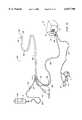
- FIG. 1is a perspective view of an electrosurgical system incorporating a power supply and an electrosurgical probe for tissue ablation, resection, incision, contraction and for vessel hemostasis according to the present invention.
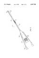
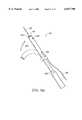
- FIG. 2is a side view of an electrosurgical probe according to the present invention.
- FIG. 3is an end view of the probe of FIG. 2.
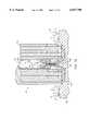
- FIG. 4is a cross sectional view of the electrosurgical probe of FIG. 1.
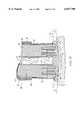
- FIG. 5is an exploded view of a proximal portion of the electrosurgical probe.
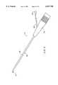
- FIG. 6is a perspective view of an alternative electrosurgical probe incorporating an inner fluid lumen.
- FIGS. 7A-7Care cross-sectional views of the distal portions of three different embodiments of an electrosurgical probe according to the present invention.
- FIGS. 8A and 8Bare cross-sectional and end views, respectively, of yet another electrosurgical probe incorporating flattened electrode terminals particularly useful for cutting tissue;
- FIG. 9illustrates an electrosurgical probe with a 90° distal bend and a lateral fluid lumen
- FIG. 10illustrates an electrosurgical system with a separate fluid delivery instrument according to the present invention
- FIGS. 11A and 11Bare perspective and end views, respectively, of an electrosurgical probe particularly useful for forming holes or channels in tissue, such as a commissurotomy of a calcified valve;
- FIG. 12is a perspective view of an electrosurgical catheter system for removing calcified deposits or other matter from a heart valve
- FIG. 13illustrates the distal portion of an electrosurgical catheter for use with the system of FIG. 12;
- FIG. 14A and 14Bare cross-sectional and end views, respectively of a distal portion of a second electrosurgical catheter according to the present invention.
- FIGS. 15A-15Dshow alternative embodiments of the present invention.
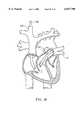
- FIG. 16is a schematic of the heart showing the location of various heart valves
- FIGS. 17A-17Bare overhead and side views of a tricuspid valve
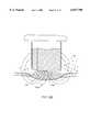
- FIG. 18is a partial cross-sectional view of the heart being treated by a device according to the present invention.
- FIG. 19Ashows a device of the present invention treating an aortic semilunar valve
- FIG. 19Bshows a device of the present invention performing a commissurotomy
- FIG. 20shows a device of the present invention used in a port access procedure in the chest of a patient.
- FIGS. 21A-21Billustrate a detailed view of the calcium removal procedure, illustrating ablation of tissue according to the present invention.
- the present inventionprovides systems and methods for selectively applying electrical energy to a target location within or on a patient's body, particularly including tissue in the heart such as the leaflets of the mitral and aortic valves.
- the methods and apparatus of the present inventionare also useful for removing atheromatous material which partially or fully occludes a body lumen, such as a blood vessel.
- the methods and apparatus disclosed hereinmay be used in a wide variety of procedures, including open procedures, intravascular procedures, urology, laparascopy, arthroscopy, thoracoscopy or other cardiac procedures, dermatology, orthopedics, gynecology, otorhinolaryngology, spinal and neurologic procedures, oncology and the like.
- the remaining disclosurewill be directed specifically to the removal of undesirable material from cardiac tissue, such as calcified deposits or plaque.
- high frequency (RF) electrical energyis applied to one or more electrode terminals in the presence of electrically conductive fluid to remove and/or modify the structure of tissue structures.
- the present inventionmay be used to: (1) volumetrically remove tissue or cartilage (i.e., ablate or effect molecular dissociation of the tissue structure); (2) cut or resect tissue; (3) shrink or contract collagen connective tissue; and/or (4) coagulate severed blood vessels.
- the present inventionis particularly useful for ablation and/or hemostasis.
- the calcified plaque deposits on the leafletsmay be extremely hard and difficult to remove.
- the electrosurgical device of the present inventioncan cauterize and seal small blood vessels in tissue which may be exposed during valve leaflet removal.
- the present inventionmay be used to sculpt and remove calcified material surrounding valves to be repaired or replaced. This reduces the amount of obstructive material which may complicate placement of the prosthetic valve or facilitate a restenotic effect.
- the techniques of the present inventionmay be performed percutaneously by introducing an electrosurgical instrument into the patient's vasculature and advancing the instrument transluminally to a target site. These procedures may also be performed through other minimally invasive methods such as port access or "key-hole" operations as under development by companies such as Heartport of Redwood City, Calif. and Cardiothoracic Systems of Portola Valley, Calif. These procedures may further be performed using traditional open surgery techniques.
- the present inventionis particularly useful for removing small amounts of calcified tissue and other materials with minimal damage to the underlying valve leaflet and with minimal disruption of the elastic fiber layer in the valve leaflets. Maintaining the elasticity of the valves minimizes later stenosis or regurgitation of blood flow.
- calcified deposits and plaque on cardiac tissueare volumetrically removed or ablated.
- a high frequency voltage differenceis applied between one or more electrode terminal(s) and one or more return electrode(s) to develop high electric field intensities in the vicinity of the target tissue.
- the high electric field intensities adjacent the electrode terminal(s)lead to electric field induced molecular breakdown of target tissue through molecular dissociation (rather than thermal evaporation or carbonization).
- Applicantbelieves that the tissue structure is volumetrically removed through molecular disintegration of larger organic molecules into smaller molecules and/or atoms, such as hydrogen, oxygen, oxides of carbon, hydrocarbons and nitrogen compounds. This molecular disintegration completely removes the tissue structure, as opposed to dehydrating the tissue material by the removal of liquid within the cells of the tissue, as is typically the case with electrosurgical desiccation and vaporization.
- the high electric field intensitiesmay be generated by applying a high frequency voltage that is sufficient to vaporize an electrically conducting fluid over at least a portion of the electrode terminal(s) in the region between the distal tip of the electrode terminal(s) and the target tissue.
- the electrically conductive fluidmay be a liquid, such as isotonic saline or blood, delivered to the target site, or a viscous fluid, such as a gel, applied to the target site. Since the vapor layer or vaporized region has a relatively high electrical impedance, it increases the voltage differential between the electrode terminal tip and the tissue and causes ionization within the vapor layer due to the presence of an ionizable species (e.g., sodium when isotonic saline is the electrically conducting fluid).
- an ionizable speciese.g., sodium when isotonic saline is the electrically conducting fluid.
- This ionizationinduces the discharge of energetic electrons and photons from the vapor layer and to the surface of the target tissue.
- This energymay be in the form of energetic photons (e.g., ultraviolet radiation), energetic particles (e.g., electrons) or a combination thereof.
- energetic photonse.g., ultraviolet radiation
- energetic particlese.g., electrons
- CoblationTMA more detailed description of this phenomena, termed CoblationTM can be found in commonly assigned U.S. Pat. No. 5,683,366 the complete disclosure of which is incorporated herein by reference.
- the present inventionapplies high frequency (RF) electrical energy in an electrically conducting fluid environment to remove (i.e., resect, cut or ablate) a tissue structure, and to seal transected vessels within the region of the target tissue.
- RFhigh frequency
- the present inventionis particularly useful for sealing larger arterial vessels, e.g., on the order of 1 mm or greater.
- a high frequency power supplyis provided having an ablation mode, wherein a first voltage is applied to an electrode terminal sufficient to effect molecular dissociation or disintegration of the tissue, and a coagulation mode, wherein a second, lower voltage is applied to an electrode terminal (either the same or a different electrode) sufficient to achieve hemostasis of severed vessels within the tissue.
- an electrosurgical instrumenthaving one or more coagulation electrode(s) configured for sealing a severed vessel, such as an arterial vessel, and one or more electrode terminals configured for either contracting the collagen fibers within the tissue or removing (ablating) the tissue, e.g., by applying sufficient energy to the tissue to effect molecular dissociation.
- the coagulation electrode(s)may be configured such that a single voltage can be applied to coagulate with the coagulation electrode(s), and to ablate with the electrode terminal(s).
- the power supplyis combined with the coagulation instrument such that the coagulation electrode is used when the power supply is in the coagulation mode (low voltage), and the electrode terminal(s) are used when the power supply is in the ablation mode (higher voltage).
- the present inventionis also useful for removing or ablating tissue around nerves, such as spinal, visceral or cranial nerves, e.g., the olfactory nerve on either side of the nasal cavity, the optic nerve within the optic and cranial canals, the palatine nerve within the nasal cavity, soft palate, uvula and tonsil, etc.
- nervessuch as spinal, visceral or cranial nerves, e.g., the olfactory nerve on either side of the nasal cavity, the optic nerve within the optic and cranial canals, the palatine nerve within the nasal cavity, soft palate, uvula and tonsil, etc.
- nervessuch as spinal, visceral or cranial nerves, e.g., the olfactory nerve on either side of the nasal cavity, the optic nerve within the optic and cranial canals, the palatine nerve within the nasal cavity, soft palate, uvula and tonsil, etc.
- one or more electrode terminalsare brought into close proximity to tissue at a target site, and the power supply is activated in the ablation mode such that sufficient voltage is applied between the electrode terminals and the return electrode to volumetrically remove the tissue through molecular dissociation, as described below.
- the power supplyis activated in the ablation mode such that sufficient voltage is applied between the electrode terminals and the return electrode to volumetrically remove the tissue through molecular dissociation, as described below.
- vessels within the tissuewill be severed. Smaller vessels will be automatically sealed with the system and method of the present invention. Larger vessels, and those with a higher flow rate, such as arterial vessels, may not be automatically sealed in the ablation mode. In these cases, the severed vessels may be sealed by activating a control (e.g., a foot pedal) to reduce the voltage of the power supply into the coagulation mode.
- a controle.g., a foot pedal
- the electrode terminalsmay be pressed against the severed vessel to provide sealing and/or coagulation of the vessel.
- a coagulation electrode located on the same or a different instrumentmay be pressed against the severed vessel.
- the electrosurgical instrumentwill comprise a shaft having a proximal end and a distal end which supports one or more electrode terminal(s).
- the shaftmay assume a wide variety of configurations, with the primary purpose being to mechanically support one or more electrode terminal(s) and permit the treating physician to manipulate the electrode(s) from a proximal end of the shaft.
- an electrosurgical probe shaftwill be a narrow-diameter rod or tube, more usually having dimensions which permit it to be introduced into a body cavity, such as the thoracic cavity, through an associated trocar or cannula in a minimally invasive procedure, such as arthroscopic, laparoscopic, thoracoscopic (e.g., Port AccessTM) and other endoscopic procedures.
- the probe shaftwill typically have a length of at least 5 cm for open procedures and at least 10 cm, more typically being 20 cm, or longer for endoscopic procedures.
- the probe shaftwill typically have a diameter of at least 1 mm and frequently in the range from 1 to 10 mm.
- the electrosurgical instrumentmay be delivered percutaneously and/or endoluminally to the ventricular cavity of the heart by insertion through a conventional or specialized guide catheter, or the invention may include a catheter having an active electrode or electrode array integral with its distal end.
- the catheter shaftmay be rigid or flexible, with flexible shafts optionally being combined with a generally rigid external tube for mechanical support. Flexible shafts may be combined with pull wires, shape memory actuators, and other known mechanisms for effecting selective deflection of the distal end of the shaft to facilitate positioning of the electrode or electrode array.
- the catheter haftwill usually include a plurality of wires or other conductive elements running axially therethrough to permit connection of the electrode or electrode array and the return electrode to a connector at the proximal end of the catheter shaft.
- the catheter shaftmay include a guide wire for guiding the catheter to the target site, or the catheter may comprise a steerable guide catheter.
- the cathetermay also include a substantially rigid distal end portion to increase the torque control of the distal end portion as the catheter is advanced further into the patient's body.
- the electrode terminal(s)are preferably supported within or by an inorganic insulating support positioned near the distal end of the instrument shaft, e.g., a catheter body.
- the return electrodemay be located on the instrument shaft, on another instrument or on the external surface of the patient (i.e., a dispersive pad).
- the return electrodeis preferably either integrated with the catheter body, or another instrument located in close proximity to the distal end of he catheter body.
- the proximal end of the catheterwill include the appropriate electrical connections for coupling the return electrode(s) and the electrode terminal(s) to a high frequency power supply, such as an electrosurgical generator.
- the current flow path between the electrode terminals and the return electrode(s)may be generated by submerging the tissue site in an electrical conducting fluid (e.g., within a viscous fluid, such as an electrically conductive gel) or by directing an electrically conducting fluid along a fluid path to the target site (i.e., a liquid, such as isotonic saline, or a gas, such as argon).
- an electrical conducting fluide.g., within a viscous fluid, such as an electrically conductive gel
- a fluid pathi.e., a liquid, such as isotonic saline, or a gas, such as argon.
- the conductive gelmay also be delivered to the target site to achieve a slower more controlled delivery rate of conductive fluid.
- the viscous nature of the gelmay allow the surgeon to more easily contain the gel around the target site (e.g., rather than attempting to contain isotonic saline).
- a liquid electrically conductive fluide.g., isotonic saline
- isotonic salinemay be used to concurrently "bathe" the target tissue surface to provide an additional means for removing any tissue, and to cool the region of the target tissue ablated in the previous moment.
- the power supplymay include a fluid interlock for interrupting power to the electrode terminal(s) when there is insufficient conductive fluid around the electrode terminal(s). This ensures that the instrument will not be activated when conductive fluid is not present, minimizing the tissue damage that may otherwise occur.
- a fluid interlockcan be found in commonly assigned, co-pending U.S. application. Ser. No. 09/058,336, filed Apr. 10, 1998 (attorney Docket No. CB-4), the complete disclosure of which is incorporated herein by reference.
- the system of the present inventionmay include one or more suction lumen(s) in the instrument, or on another instrument, coupled to a suitable vacuum source for aspirating fluids from the target site.
- suctionit may be desirable to contain the excess electrically conductive fluid, tissue fragments and/or gaseous products of ablation at or near the target site with a containment apparatus, such as a basket, retractable sheath or the like.
- a containment apparatussuch as a basket, retractable sheath or the like.
- This embodimenthas the advantage of ensuring that the conductive fluid, tissue fragments or ablation products do not flow into the heart or lungs.
- the present inventionmay use a single active electrode terminal or an array of electrode terminals spaced around the distal surface of a catheter or probe.
- the electrode arrayusually includes a plurality of independently current-limited and/or power-controlled electrode terminals to apply electrical energy selectively to the target tissue while limiting the unwanted application of electrical energy to the surrounding tissue and environment resulting from power dissipation into surrounding electrically conductive fluids, such as blood, normal saline, and the like.
- the electrode terminalsmay be independently current-limited by isolating the terminals from each other and connecting each terminal to a separate power source that is isolated from the other electrode terminals.
- the electrode terminalsmay be connected to each other at either the proximal or distal ends of the catheter to form a single wire that couples to a power source.
- each individual electrode terminal in the electrode arrayis electrically insulated from all other electrode terminals in the array within said instrument and is connected to a power source which is isolated from each of the other electrode terminals in the array or to circuitry which limits or interrupts current flow to the electrode terminal when low resistivity material (e.g., blood, electrically conductive saline irrigant or electrically conductive gel) causes a lower impedance path between the return electrode and the individual electrode terminal.
- the isolated power sources for each individual electrode terminalmay be separate power supply circuits having internal impedance characteristics which limit power to the associated electrode terminal when a low impedance return path is encountered.
- the isolated power sourcemay be a user selectable constant current source.
- a single power sourcemay be connected to each of the electrode terminals through independently actuatable switches, or by independent current limiting elements, such as inductors, capacitors, resistors and/or combinations thereof.
- the current limiting elementsmay be provided in the instrument, connectors, cable, controller or along the conductive path from the controller to the distal tip of the instrument.
- the resistance and/or capacitancemay occur on the surface of the active electrode terminal(s) due to oxide layers which form selected electrode terminals (e.g., titanium or a resistive coating on the surface of metal, such as platinum).
- the tip region of the instrumentmay comprise many independent electrode terminals designed to deliver electrical energy in the vicinity of the tip.
- the selective application of electrical energy to the conductive fluidis achieved by connecting each individual electrode terminal and the return electrode to a power source having independently controlled or current limited channels.
- the return electrode(s)may comprise a single tubular member of conductive material proximal to the electrode array at the tip which also serves as a conduit for the supply of the electrically conducting fluid between the active and return electrodes.
- the instrumentmay comprise an array of return electrodes at the distal tip of the instrument (together with the active electrodes) to maintain the electric current at the tip.
- the application of high frequency voltage between the return electrode(s) and the electrode arrayresults in the generation of high electric field intensities at the distal tips of the electrode terminals with conduction of high frequency current from each individual electrode terminal to the return electrode.
- the current flow from each individual electrode terminal to the return electrode(s)is controlled by either active or passive means, or a combination thereof, to deliver electrical energy to the surrounding conductive fluid while minimizing energy delivery to surrounding (non-target) tissue.
- the application of a high frequency voltage between the return electrode(s) and the electrode terminal(s) for appropriate time intervalseffects cutting, removing, ablating, shaping, contracting or otherwise modifying the target tissue.
- the tissue volume over which energy is dissipatedi.e., a high current density exists
- the tissue volume over which energy is dissipatedmay be precisely controlled, for example, by the use of a multiplicity of small electrode terminals whose effective diameters or principal dimensions range from about 5 mm to 0.01 mm, preferably from about 2 mm to 0.05 mm, and more preferably from about 1 mm to 0.1 mm.
- Electrode areas for both circular and non-circular terminalswill have a contact area (per electrode terminal) below 25 mm 2 for electrode arrays and as large as 75 mm 2 for single electrode embodiments, preferably being in the range from 0.0001 mm 2 to 1 mm 2 , and more preferably from 0.005 mm 2 to 0.5 mm 2 .
- the circumscribed area of the electrode arrayis in the range from 0.25 mm 2 to 75 mm 2 , preferably from 0.5 mm 2 to 40 mm 2 , and will usually include at least one includes, often at least two isolated electrode terminals, often at least five electrode terminals, often greater than 10 electrode terminals and even 50 or more electrode terminals, disposed over the distal contact surfaces on the shaft.
- the use of small diameter electrode terminalsincreases the electric field intensity and reduces the extent or depth of tissue heating as a consequence of the divergence of current flux lines which emanate from the exposed surface of each electrode terminal.
- the area of the tissue treatment surfacecan vary widely, and the tissue treatment surface can assume a variety of geometries, with particular areas and geometries being selected for specific applications.
- the active electrode surface(s)can have area(s) in the range from 0.25 mm 2 to 75 mm 2 , usually being from about 0.5 mm 2 to 40 mm 2 .
- the geometriescan be planar, concave, convex, hemispherical, conical, linear "in-line” array or virtually any other regular or irregular shape.
- the active electrode(s) or electrode terminal(s)will be formed at the distal tip of the electrosurgical instrument shaft, frequently being planar, disk-shaped, or hemispherical surfaces for use in reshaping procedures or being linear arrays for use in cutting.
- the active electrode(s)may be formed on lateral surfaces of the electrosurgical instrument shaft (e.g., in the manner of a spatula), facilitating access to certain body structures in endoscopic procedures.
- the electrode support and the fluid outletmay be recessed from an outer surface of the instrument or handpiece to confine the electrically conductive fluid to the region immediately surrounding the electrode support.
- the shaftmay be shaped so as to form a cavity around the electrode support and the fluid outlet. This helps to assure that the electrically conductive fluid will remain in contact with the electrode terminal(s) and the return electrode(s) to maintain the conductive path therebetween. In addition, this will help to maintain a vapor layer and subsequent plasma layer between the electrode terminal(s) and the tissue at the treatment site throughout the procedure, which reduces the thermal damage that might otherwise occur if the vapor layer were extinguished due to a lack of conductive fluid. Provision of the electrically conductive fluid around the target site also helps to maintain the tissue temperature at desired levels.
- the electrically conducting fluidshould have a threshold conductivity to provide a suitable conductive path between the return electrode and the electrode terminal(s).
- the electrical conductivity of the fluid(in units of milliSiemans per centimeter or mS/cm) will usually be greater than 0.2 mS/cm, preferably will be greater than 2 mS/cm and more preferably greater than 10 mS/cm.
- the electrically conductive fluidis isotonic saline, which has a conductivity of about 17 mS/cm.
- the voltage difference applied between the return electrode(s) and the electrode terminal(s)will be at high or radio frequency, typically between about 5 kHz and 20 MHz, usually being between about 30 kHz and 2.5 MHz, preferably being between about 50 kHz and 500 kHz, more preferably less than 350 kHz, and most preferably between about 100 kHz and 200 kHz.
- the RMS (root mean square) voltage appliedwill usually be in the range from about 5 volts to 1000 volts, preferably being in the range from about 10 volts to 500 volts depending on the electrode terminal size, the operating frequency and the operation mode of the particular procedure or desired effect on the tissue (i.e., contraction, coagulation, cutting or ablation).
- the peak-to-peak voltage for ablation or cuttingwill be in the range of 10 to 2000 volts and preferably in the range of 200 to 1800 volts and more preferably in the range of about 300 to 1500 volts, often in the range of about 500 to 900 volts peak to peak (again, depending on the electrode size, the operating frequency and the operation mode).
- Lower peak-to-peak voltageswill be used for tissue coagulation or collagen contraction and will typically be in the range from 50 to 1500, preferably 100 to 1000 and more preferably 120 to 600 volts peak-to-peak.
- the voltageis usually delivered in a series of voltage pulses or alternating current of time varying voltage amplitude with a sufficiently high frequency (e.g., on the order of 5 kHz to 20 MHz) such that the voltage is effectively applied continuously (as compared with e.g., lasers claiming small depths of necrosis, which are generally pulsed about 10 to 20 Hz).
- the duty cyclei.e., cumulative time in any one-second interval that energy is applied
- the preferred power source of the present inventiondelivers a high frequency current selectable to generate average power levels ranging from several milliwatts to tens of watts per electrode, depending on the volume of target tissue being heated, and/or the maximum allowed temperature selected for the instrument tip.
- the power sourceallows the user to select the voltage level according to the specific requirements of a particular cardiac surgery, arthroscopic surgery, dermatological procedure, ophthalmic procedures, open surgery or other endoscopic surgery procedure.
- the power sourcemay have an additional filter, for filtering leakage voltages at frequencies below 100 kHz, particularly voltages around 60 kHz.
- a description of a suitable power sourcecan be found in co-pending patent applications Ser. Nos. 09/058,571 and 09/058,336, filed Apr. 10, 1998 (Attorney Docket Nos. CB-2 and CB-4), the complete disclosure of both applications are incorporated herein by reference for all purposes.
- the power sourcemay be current limited or otherwise controlled so that undesired heating of the target tissue or surrounding (non-target) tissue does not occur.
- current limiting inductorsare placed in series with each independent electrode terminal, where the inductance of the inductor is in the range of 10 uH to 50,000 uH, depending on the electrical properties of the target tissue, the desired tissue heating rate and the operating frequency.
- capacitor-inductor (LC) circuit structuresmay be employed, as described previously in U.S. Pat. No. 5,697,909, the complete disclosure of which is incorporated herein by reference. Additionally, current limiting resistors may be selected.
- these resistorswill have a large positive temperature coefficient of resistance so that, as the current level begins to rise for any individual electrode terminal in contact with a low resistance medium (e.g., saline irrigant or blood), the resistance of the current limiting resistor increases significantly, thereby minimizing the power delivery from said electrode terminal into the low resistance medium (e.g., saline irrigant or blood).
- a low resistance mediume.g., saline irrigant or blood
- control systemis "tuned” so that it will not apply excessive power to the blood (e.g., in the ventricle), once it crosses the wall of the heart and enters the chamber of the left ventricle. This minimizes the formation of a thrombus in the heart (i.e., will not induce thermal coagulation of the blood).
- the control systemmay include an active or passive architecture, and will typically include a mechanism for sensing resistance between a pair(s) of active electrodes at the distal tip, or between one or more active electrodes and a return electrode, to sense when the electrode array has entered into the blood-filled chamber of the left ventricle.
- an ultrasound transducer at the tip of the instrumentcan be used to detect the boundary between the abnormal tissue layer (e.g., calcified deposits) and healthy underlying tissue.
- the inventionis not limited to electrically isolated electrode terminals, or even to a plurality of electrode terminals.
- the array of active electrode terminalsmay be connected to a single lead that extends through the catheter shaft to a power source of high frequency current.
- the cathetermay incorporate a single electrode that extends directly through the catheter shaft or is connected to a single lead that extends to the power source.
- the active electrode(s)may have ball shapes (e.g., for tissue vaporization and desiccation), twizzle shapes (for vaporization and needle-like cutting), spring shapes (for rapid tissue debulking and desiccation), twisted metal shapes, annular or solid tube shapes or the like.
- the electrode(s)may comprise a plurality of filaments, rigid or flexible brush electrode(s) (for debulking a tumor, such as a fibroid, bladder tumor or a prostate adenoma), side-effect brush electrode(s) on a lateral surface of the shaft, coiled electrode(s) or the like.
- an electrosurgical catheter or probecomprises a single active electrode terminal that extends from an insulating member, e.g., ceramic, at the distal end of the shaft.
- the insulating memberis preferably a tubular structure that separates the active electrode terminal from a tubular or annular return electrode positioned proximal to the insulating member and the active electrode.
- the catheter or probeincludes a single active electrode that can be rotated relative to the rest of the catheter body, or the entire catheter may be rotated related to the lead.
- the single active electrodecan be positioned adjacent the abnormal tissue (e.g., calcified deposits) and energized and rotated as appropriate to remove this tissue.
- the current flow path between the electrode terminal(s) and the return electrode(s)may be generated by submerging the tissue site in an electrical conducting fluid (e.g., within a viscous fluid, such as an electrically conductive gel) or by directing an electrically conducting fluid along a fluid path to the target site (i.e., a liquid, such as isotonic saline, or a gas, such as argon).
- an electrical conducting fluide.g., within a viscous fluid, such as an electrically conductive gel
- an electrically conducting fluidalong a fluid path to the target site (i.e., a liquid, such as isotonic saline, or a gas, such as argon).
- Electrosurgical system 11generally comprises an electrosurgical handpiece or probe 10 connected to a power supply 28 for providing high frequency voltage to a target site and a fluid source 21 for supplying electrically conducting fluid 50 to probe 10.
- electrosurgical system 11may include an endoscope (not shown) with a fiber optic head light for viewing the surgical site, if desired.
- the endoscopemay be integral with probe 10, or it may be part of a separate instrument.
- the system 11may also include a vacuum source (not shown) for coupling to a suction lumen or tube 220 (see FIG. 2) in the probe 10 for aspirating the target site.
- probe 10generally includes a proximal handle 19 and an elongate shaft 18 having an array 12 of electrode terminals 58 at its distal end.
- a connecting cable 34has a connector 26 for electrically coupling the electrode terminals 58 to power supply 28.
- the electrode terminals 58are electrically isolated from each other and each of the terminals 58 is connected to an active or passive control network within power supply 28 by means of a plurality of individually insulated conductors (not shown).
- a fluid supply tube 15is connected to a fluid tube 14 of probe 10 for supplying electrically conductive fluid 50 to the target site. Conductive fluid 50 may be driven by gravity or with a suitable pump.
- Power supply 28has an operator controllable voltage level adjustment 30 to change the applied voltage level, which is observable at a voltage level display 32.
- Power supply 28also includes first, second and third foot pedals 37, 38, 39 and a cable 36 which is removably coupled to power supply 28.
- the foot pedals 37, 38, 39allow the surgeon to remotely adjust the energy level applied to electrode terminals 58.
- first foot pedal 37is used to place the power supply into the "ablation” mode and second foot pedal 38 places power supply 28 into the "subablation” mode (e.g., coagulation, tissue contraction or the like).
- the third foot pedal 39allows the user to adjust the voltage level within the "ablation" mode.
- a sufficient voltageis applied to the electrode terminals to establish the requisite conditions for molecular dissociation of the tissue (i.e., vaporizing a portion of the electrically conductive fluid, ionizing charged particles within the vapor layer and accelerating these charged particles against the tissue).
- the requisite voltage level for ablationwill vary depending on the number, size, shape and spacing of the electrodes, the distance in which the electrodes extend from the support member, etc.
- the power supply 28applies a low enough voltage to the electrode terminals to avoid vaporization of the electrically conductive fluid and subsequent molecular dissociation of the tissue.
- the surgeonmay automatically toggle the power supply between the ablation and subablation modes by alternatively stepping on foot pedals 37, 38, respectively. This allows, for example, the surgeon to quickly move between coagulation and ablation in situ, without having to remove his/her concentration from the surgical field or without having to request an assistant to switch the power supply.
- the probetypically will simultaneously seal and/or coagulation small severed vessels within the tissue.
- FIGS. 2-5illustrate an exemplary electrosurgical probe 90 constructed according to the principles of the present invention.
- probe 90generally includes an elongated shaft 100 which may be flexible or rigid, a handle 204 coupled to the proximal end of shaft 100 and an electrode support member 102 coupled to the distal end of shaft 100.
- Shaft 100preferably comprises a plastic material that is easily molded into the shape shown in FIG. 1.
- shaft 100may comprise an electrically conducting material, usually metal, which is selected from the group comprising tungsten, stainless steel alloys, platinum or its alloys, titanium or its alloys, molybdenum or its alloys, and nickel or its alloys.
- shaft 100includes an electrically insulating jacket, which is typically formed as one or more electrically insulating sheaths or coatings, such as polytetrafluoroethylene, polyimide, and the like.
- electrically insulating jacketover the shaft prevents direct electrical contact between these metal elements and any adjacent body structure or the surgeon. Such direct electrical contact between a body structure (e.g., tendon) and an exposed electrode could result in unwanted heating and necrosis of the structure at the point of contact causing necrosis.
- Handle 204typically comprises a plastic material that is easily molded into a suitable shape for handling by the surgeon. Handle 204 defines an inner cavity (not shown) that houses the electrical connections 250 (FIG. 5), and provides a suitable interface for connection to an electrical connecting cable 22 (see FIG. 1). Electrode support member 102 extends from the distal end of shaft 100 (usually about 1 to 20 mm), and provides support for a plurality of electrically isolated electrode terminals 104 (see FIGS. 3 and 4). As shown in FIG. 2, a fluid tube 233 extends through an opening in handle 204, and includes a connector 235 for connection to a fluid supply source, for supplying electrically conductive fluid to the target site.
- fluid tube 233may extend through a single lumen (not shown) in shaft 100, or it may be coupled to a plurality of lumens (also not shown) that extend through shaft 100 to a plurality of openings at its distal end.
- fluid tube 233extends along the exterior of shaft 100 to a point just proximal of return electrode 112 (see FIG. 4).
- the fluidis directed through an opening 237 past return electrode 112 to the electrode terminals 104.
- Probe 90may also include a valve 17 (FIG. 1) or equivalent structure for controlling the flow rate of the electrically conducting fluid to the target site.
- Electrode support member 102has a substantially planar tissue treatment surface 212 (FIG. 3) that is usually at an angle of about 10 to 90 degrees relative to the longitudinal axis of shaft 100, although the shaft may have no angle at all.
- the distal portion of shaft 100comprises a flexible material which can be deflected relative to the longitudinal axis of the shaft. Such deflection may be selectively induced by mechanical tension of a pull wire, for example, or by a shape memory wire that expands or contracts by externally applied temperature changes.
- probe 90includes a return electrode 112 for completing the current path between electrode terminals 104 and a high frequency power supply 28 (see FIG. 1).
- return electrode 112preferably comprises an annular conductive band coupled to the distal end of shaft 100 slightly proximal to tissue treatment surface 212 of electrode support member 102, typically about 0.5 to 10 mm and more preferably about 1 to 10 mm.
- the shaftcomprises a conductive material, the shaft will have an exposed portion that functions as the return electrode.
- Return electrode 112is coupled to a connector (not shown) that extends to the proximal end of probe 10, where it is suitably connected to power supply 10 (FIG. 1).
- return electrode 112is not directly connected to electrode terminals 104.
- electrically conducting fluide.g., isotonic saline
- the electrically conducting fluidis delivered through fluid tube 233 to opening 237, as described above.
- the fluidmay be delivered by a fluid delivery element (not shown) that is separate from probe 90.
- the body cavitywill be flooded with isotonic saline and the probe 90 will be introduced into this flooded cavity. Electrically conducting fluid will be continually resupplied to maintain the conduction path between return electrode 112 and electrode terminals 104.
- the fluid pathmay be formed in probe 90 by, for example, an inner lumen or an annular gap between the return electrode and a tubular support member within shaft 100 (see FIG. 6).
- This annular gapmay be formed near the perimeter of the shaft 100 such that the electrically conducting fluid tends to flow radially inward towards the target site, or it may be formed towards the center of shaft 100 so that the fluid flows radially outward.
- a fluid sourcee.g., a bag of fluid elevated above the surgical site or suitable pumping device
- a fluid supply tube(not shown) that may or may not have a controllable valve.
- the electrically isolated electrode terminals 104are spaced apart over tissue treatment surface 212 of electrode support member 102.
- the tissue treatment surface and individual electrode terminals 104will usually have dimensions within the ranges set forth above.
- the tissue treatment surface 212has a circular cross-sectional shape with a diameter in the range of about 1 to 20 mm.
- the individual electrode terminals 104preferably extend outward from tissue treatment surface 212 by a distance of about 0.0 to 4 mm, usually about 0.2 to 2 mm. Applicant has found that this configuration increases the high electric field intensities and associated current densities around electrode terminals 104 to facilitate the ablation of tissue as described in detail above.
- the probeincludes a single, larger opening 209 in the center of tissue treatment surface 212, and a plurality of electrode terminals (e.g., about 3 to 15 electrode terminals) around the perimeter of surface 212 (see FIG. 3).
- the probemay include a single, annular, or partially annular, electrode terminal at the perimeter of the tissue treatment surface.
- the central opening 209is coupled to a suction lumen 215 within shaft 100 and a suction tube 211 (FIG. 2) for aspirating tissue, fluids, calcified fragments and/or gases from the target site.
- the electrically conductive fluidgenerally flows radially inward past electrode terminals 104 and then back through the opening 209. Aspirating the electrically conductive fluid during surgery allows the surgeon to see the target site, and it prevents the dispersal of gases, tissue fragments and/or calcified deposits into the patient's body.
- the probe 90will also include one or more aspiration electrode(s) (not shown) coupled to the aspiration lumen 215 for inhibiting clogging during aspiration of tissue fragments from the surgical site.
- aspiration electrode(s)not shown
- a more complete description of these embodimentscan be found in commonly assigned co-pending application Ser. No. 09/010,382, filed Jan. 21, 1998 (Attorney Docket No. A-6), the complete disclosure of which is incorporated herein by reference for all purposes.
- FIG. 5illustrates the electrical connections 250 within handle 204 for coupling electrode terminals 104 and return electrode 112 to the power supply 28.
- a plurality of wires 252extend through shaft 100 to couple terminals 104 to a plurality of pins 254, which are plugged into a connector block 256 for coupling to a connecting cable 22 (FIG. 1).
- return electrode 112is coupled to connector block 256 via a wire 258 and a pin 260.
- the probe 90further includes an identification element that is characteristic of the particular electrode assembly so that the same power supply 28 can be used for different electrosurgical operations.
- the probe 90includes a voltage reduction element or a voltage reduction circuit for reducing the voltage applied between the electrode terminals 104 and the return electrode 112.
- the voltage reduction elementserves to reduce the voltage applied by the power supply so that the voltage between the electrode terminals and the return electrode is low enough to avoid excessive power dissipation into the electrically conducting medium and/or ablation of the soft tissue at the target site.
- the voltage reduction elementprimarily allows the electrosurgical probe 90 to be compatible with other ArthroCare generators that are adapted to apply higher voltages for ablation or vaporization of tissue.
- the voltage reduction elementwill serve to reduce a voltage of about 100 to 135 volts rms (which is a setting of 1 on the ArthroCare Models 970, 980 and 2000 Generators) to about 45 to 60 volts rms, which is a suitable voltage for contraction of tissue without ablation (e.g., molecular dissociation) of the tissue.
- the probewill typically not require a voltage reduction element.
- the probemay include a voltage increasing element or circuit, if desired.
- the voltage reduction elementis a dropping capacitor 262 which has first leg 264 coupled to the return electrode wire 258 and a second leg 266 coupled to connector block 256.
- the capacitormay be located in other places within the system, such as is in, or distributed along the length of: (1) the cable; (2) in the generator; (3) in the connector, etc.
- other voltage reduction elementssuch as diodes, transistors, inductors, resistors, capacitors or combinations thereof, may be used in conjunction with the present invention.
- the probe 90may include a coded resistor (not shown) that is constructed to lower the voltage applied between return electrode 112 and electrode terminals 104 to a suitable level for contraction of tissue.
- electrical circuitsmay be employed for this purpose.
- the cable 22 that couples the power supply 10 to the probe 90may be used as a voltage reduction element.
- the cablehas an inherent capacitance that can be used to reduce the power supply voltage if the cable is placed into the electrical circuit between the power supply, the electrode terminals and the return electrode.
- the cable 22may be used alone, or in combination with one of the voltage reduction elements discussed above, e.g., a capacitor.
- the present inventioncan be used with a power supply that is adapted to apply a voltage within the selected range for treatment of tissue.
- a voltage reduction element or circuitrymay not be desired.
- FIGS. 7A-7Cschematically illustrate the distal portion of three different embodiments of probe 90 according to the present invention.
- electrode terminals 104are anchored in a support matrix 102 of suitable insulating material (e.g., ceramic or glass material, such as alumina, silicon nitride zirconia and the like) which could be formed at the time of manufacture in a flat, hemispherical or other shape according to the requirements of a particular procedure.
- suitable insulating materiale.g., ceramic or glass material, such as alumina, silicon nitride zirconia and the like
- the preferred support matrix materialis alumina, available from Kyocera Industrial Ceramics Corporation, Elkgrove, Ill., because of its high thermal conductivity, good thermal shock resistance, good electrically insulative properties, high flexural modulus, resistance to carbon tracking, biocompatibility, and high melting point.
- the support matrix 102is adhesively joined to a tubular support member 78 that extends most or all of the distance between matrix 102 and the proximal end of probe 90.
- Tubular member 78preferably comprises an electrically insulating material, such as an epoxy or silicone-based material.
- electrode terminals 104extend through pre-formed openings in the support matrix 102 so that they protrude above tissue treatment surface 212 by the desired distance.
- the electrodesare then bonded to the tissue treatment surface 212 of support matrix 102, typically by an inorganic sealing material 80.
- Sealing material 80is selected to provide effective electrical insulation, and good adhesion to both the alumina matrix 102 and the electrode terminals (e.g., titanium, tungsten, molybdenum, platinum, etc.). Sealing material 80 additionally should have a compatible thermal expansion coefficient and a melting point well below that of the metal electrode terminals and the ceramic support matrix, typically being a glass or glass ceramic.
- return electrode 112comprises an annular member positioned around the exterior of shaft 100 of probe 90.
- Return electrode 90may fully or partially circumscribe tubular support member 78 to form an annular gap 54 therebetween for flow of electrically conducting fluid 50 therethrough, as discussed below.
- Gap 54preferably has a width in the range of 0.1 mm to 4 mm.
- probemay include a plurality of longitudinal ribs between support member 78 and return electrode 112 to form a plurality of fluid lumens extending along the perimeter of shaft 100. In this embodiment, the plurality of lumens will extend to a plurality of openings.
- Return electrode 112is disposed within an electrically insulative jacket 18, which is typically formed as one or more electrically insulative sheaths or coatings, such as polytetrafluoroethylene, polyamide, and the like.
- the provision of the electrically insulative jacket 18 over return electrode 112prevents direct electrical contact between return electrode 112 and any adjacent body structure. Such direct electrical contact between a body structure (e.g., tendon) and an exposed electrode member 112 could result in unwanted heating and necrosis of the structure at the point of contact causing necrosis.
- return electrode 112is not directly connected to electrode terminals 104.
- electrically conducting fluid 50e.g., isotonic saline
- Fluid path 83is formed by annular gap 54 between outer return electrode 112 and tubular support member 78.
- the electrically conducting fluid 50 flowing through fluid path 83provides a pathway for electrical current flow between electrode terminals 104 and return electrode 112, as illustrated by the current flux lines 60 in FIG. 6A.
- FIG. 7Billustrates another alternative embodiment of electrosurgical probe 90 which has a return electrode 112 positioned within tubular member 78.
- Return electrode 112is preferably a tubular member defining an inner lumen 57 for allowing electrically conducting fluid 50 (e.g., isotonic saline) to flow therethrough in electrical contact with return electrode 112.
- electrically conducting fluid 50e.g., isotonic saline
- a voltage differenceis applied between electrode terminals 104 and return electrode 112 resulting in electrical current flow through the electrically conducting fluid 50 as shown by current flux lines 60 (FIG. 3).
- tissue 52becomes ablated or transected in zone 88.
- FIG. 7Cillustrates another embodiment of probe 90 that is a combination of the embodiments in FIGS. 7A and 7B. As shown, this probe includes both an inner lumen 57 and an outer gap or plurality of outer lumens 54 for flow of electrically conductive fluid.
- the return electrode 112may be positioned within tubular member 78 as in FIG. 7B, outside of tubular member 78 as in FIG. 7A, or in both locations.
- FIG. 9illustrates another embodiment of probe 90 where the distal portion of shaft 100 is bent so that electrode terminals extend transversely to the shaft.
- the distal portion of shaft 100is perpendicular to the rest of the shaft so that tissue treatment surface 212 is generally parallel to the shaft axis.
- return electrode 112is mounted to the outer surface of shaft 100 and is covered with an electrically insulating jacket 18.
- the electrically conducting fluid 50flows along flow path 83 through return electrode 112 and exits the distal end of electrode 112 at a point proximal of tissue treatment surface 212.
- the fluidis directed exterior of shaft to surface 212 to create a return current path from electrode terminals 104, through the fluid 50, to return electrode 12, as shown by current flux lines 60.
- FIG. 10illustrates another embodiment of the invention where electrosurgical system 11 further includes a fluid supply instrument 64 for supplying electrically conducting fluid 50 between electrode terminals 104 and return electrode 112.
- Fluid supply instrument 64comprises an inner tubular member or return electrode 112 surrounded by an electrically insulating jacket 18.
- Return electrode 112defines an inner passage 83 for flow of fluid 50.
- the distal portion of instrument 64is preferably bent so that fluid 50 is discharged at an angle with respect to instrument 64. This allows the surgical team to position fluid supply instrument 64 adjacent tissue treatment surface 212 with the proximal portion of supply instrument 64 oriented at a similar angle to probe 90.
- an alternative probe 90includes a pair of electrodes 105a, 105b mounted to the distal end of shaft 100. Electrodes 105a, 105b are electrically connected to power supply as described above and preferably have tips 107a, 107b with a screwdriver shape.
- the screwdriver shapeprovides a greater amount of "edges" to electrodes 105a, 105b, to increase the electric field intensity and current density at the edges and thereby improve the cutting ability as well as the ability to limit bleeding from the incised tissue (i.e., hemostasis).
- probe 300may be particularly useful for performing a commisurotomy in a heart valve (discussed in more detail below in reference to FIG. 19B).
- probe 300comprises a handle 302, which preferably comprises a disposable distal portion 304 removably coupled to a proximal reusable portion 306, and an elongate shaft 308 extending from distal portion 304 of handle 302.
- Shaft 308is also disposable, and is coupled to distal portion 304 of handle 302.
- the proximal and distal portions of handle 302typically comprise a plastic material that is easily molded into a suitable shape for handling by the surgeon.
- Handle 302defines an inner cavity (not shown) that houses the electrical connections (also not shown), and provides a suitable interface for connection to power supply 28 (FIG. 1).
- the proximal portion of handle 302is constructed so that it can be re-used by sterilizing handle 302 between surgical procedures.
- both the proximal and distal portions of the handlemay be reusable, or both of these handle portions may be disposable, if desired.
- Shaft 308may be sized to provide either open-chest or endoscopic access to the thoracic cavity, preferably through an intercostal space or similar percutaneous penetration in the patient. Accordingly, shaft 308 preferably has a length in the range of about 4 to 25 cm and a diameter less than 10 cm. In the exemplary embodiment, shaft 308 is also preferably sized for ablating tissue containing calcified deposits or separating adherent valve leaflets and, therefore, will have a diameter less than 5 mm, preferably less than about 3 mm. Alternatively, shaft 308 may have a distal portion that is smaller than the rest of shaft for performing such procedures. As shown in FIG.
- shaft 308includes an electrically insulating electrode support member 310 extending from its distal end (usually about 0.5 to 20 mm) to provide support for one or more electrically isolated electrode terminal(s) 312.
- electrode support member 310may be recessed from the distal end of shaft 308 to help confine the electrically conductive fluid around the electrode terminals 312 during the surgical procedure, as discussed above.
- probe 300includes an annular return electrode 314 for completing the current path between electrode terminals 12 and power supply 28.
- Return electrode 314is spaced proximally from electrode terminal(s) 312 a sufficient distance to avoid arcing therebetween.
- return electrode 314is positioned such that, when electrode terminal(s) 312 are brought adjacent a tissue structure, return electrode 314 is spaced away from the tissue structure so that the tissue structure cannot, at least by itself, complete the current flow path between electrode terminal(s) 312 and return electrode 314.
- probe 300includes a fluid tube 316 for delivering electrically conductive fluid to the target site.
- Fluid tube 316is sized to extend through a groove 318 in handle 302 and through an inner cavity (not shown) in shaft 308 to a distal opening 320 (FIG. 11B) located adjacent electrode support member 310.
- Fluid tube 315preferably extends all the way through the inner cavity to opening 320 to eliminate any possible fluid ingress into the cavity.
- fluid tube 316includes a proximal connector 322 for coupling to an electrically conductive fluid source (see FIG. 1).
- Probe 300will also include a valve or equivalent structure for controlling the flow rate of the electrically conducting fluid to the target site.
- handle 302comprises a main body 324, 326 and a rotatable sleeve 328 for controlling fluid flow through tube 316.
- Rotation of sleeve 328crimps tube 316 to limit or complete shut off flow therethrough.
- this fluid controlmay be provided by a variety of other input and valve devices, such as switches, buttons, etc.
- the fluid pathmay be directly formed in probe 300 by, for example, a central inner lumen or an annular gap (not shown) within the handle and the shaft.
- This inner lumenmay be formed near the perimeter of the probe 300 such that the electrically conducting fluid tends to flow radially inward towards the target site, or it may be formed towards the center of probe 300 so that the fluid flows radially outward.
- the electrically conducting fluidmay be delivered from a fluid delivery element (not shown) that is separate from probe 300.
- electrically isolated electrode terminals 312are circumferentially spaced around fluid opening 320 at the tissue treatment surface of electrode support member 306.
- the tissue treatment surfacehas a circular cross-sectional shape with a diameter of about 0.5 to 10 mm, usually less than 4 mm.
- the individual electrode terminals 312have the dimensions described above, and preferably extend about 0.05 to 4.0 mm from the tissue treatment surface.
- the electrode terminals 312may be substantially flush with the tissue treatment surface or the terminals may be recessed from this surface.
- the electrode terminals 312may be recessed by a distance from 0.01 mm to 2 mm, preferably 0.05 mm 5 to 1.0 mm.
- the electrode terminalsare axially adjustable relative to the tissue treatment surface so that the surgeon can adjust the distance between the surface and the electrode terminals.
- a catheter system 400generally comprises an electrosurgical catheter 460 connected to a power supply 28 by an interconnecting cable 486 for providing high frequency voltage to a target tissue site and an irrigant reservoir or source 600 for providing electrically conducting fluid to the target site.
- Catheter 460generally comprises an elongate, flexible shaft body 462 including a tissue removing or ablating region 464 at the distal end of body 462.
- the proximal portion of catheter 460includes a multi-lumen fitment 614 which provides for interconnections between lumens and electrical leads within catheter 460 and conduits and cables proximal to fitment 614.
- a catheter electrical connector 496is removably connected to a distal cable connector 494 which, in turn, is removably connectable to generator 28 through connector 492.
- One or more electrically conducting lead wires (not shown) within catheter 460extend between one or more active electrodes 463 at tissue ablating region 464 and one or more corresponding electrical terminals (also not shown) in catheter connector 496 via active electrode cable branch 487.
- one or more return electrodes 466 at tissue ablating region 464are coupled to a return electrode cable branch 489 of catheter connector 496 by lead wires (not shown).
- lead wiresnot shown
- a single cable branchmay be used for both active and return electrodes.
- Catheter body 462may include reinforcing fibers or braids (not shown) in the walls of at least the distal ablation region 464 of body 462 to provide responsive torque 30 control for rotation of electrode terminals during tissue engagement.
- This rigid portion of the catheter body 462preferably extends only about 7 to 10 mm while the remainder of the catheter body 462 is flexible to provide good trackability during advancement and positioning of the electrodes adjacent target tissue.
- Conductive fluid 30is provided to tissue ablation region 464 of catheter 460 via a lumen (not shown in FIG. 12) within catheter 460. Fluid is supplied to lumen from the source along a conductive fluid supply line 602 and a conduit 603, which is coupled to the inner catheter lumen at multi-lumen fitment 614.
- the source of conductive fluide.g., isotonic saline
- the source of conductive fluidmay be an irrigant pump system (not shown) or a gravity-driven supply, such as an irrigant reservoir 600 positioned several feet above the level of the patient and tissue ablating region 8.
- a control valve 604may be positioned at the interface of fluid supply line 602 and conduit 603 to allow manual control of the flow rate of electrically conductive fluid 30.
- a metering pump or flow regulatormay be used to precisely control the flow rate of the conductive fluid.
- System 400further includes an aspiration or vacuum system (not shown) to aspirate liquids and gases from the target site.
- the aspiration systemwill usually comprise a source of vacuum coupled to fitment 614 by a aspiration connector 605.
- FIGS. 13 and 14illustrate the working end 464 of an electrosurgical catheter 460 constructed according to the principles of the present invention.
- catheter 460generally includes an elongated shaft 462 which may be flexible or rigid, and an electrode support member 620 coupled to the distal end of shaft 462.
- Electrode support member 620extends from the distal end of shaft 462 (usually about 1 to 20 mm), and provides support for a plurality of electrically isolated electrode terminals 463.
- Electrode support member 620 and electrode terminals 463are preferably secured to a tubular support member 626 within shaft 460 by adhesive 630.
- the electrode terminals 463may be constructed using round, square, rectangular or other shaped conductive metals.
- the electrode terminal materialsmay be selected from the group including stainless steel, tungsten and its alloys, molybdenum and its alloys, titanium and its alloys, nickel-based alloys, as well as platinum and its alloys.
- Electrode support member 620is preferably a ceramic, glass or glass/ceramic composition (e.g., aluminum oxide, titanium nitride).
- electrode support member 620may include the use of high-temperature biocompatible plastics such as polyether-ether-keytone (PEEK) manufactured by Vitrex International Products, Inc. or polysulfone manufactured by GE Plastics.
- the adhesive 630may, by way of example, be an epoxy (e.g., Master Bond EP42HT manufactured by Master Bond) or a silicone-based adhesive.
- a total of 7 circular active electrodes or electrode terminals 463are shown in a symmetrical pattern having an active electrode diameter, D 1 in the range from 0.05 mm to 1.5 mm, more preferably in the range from 0.1 mm to 0.75 mm.
- the interelectrode spacings, W 1 and W 2are preferably in the range from 0.1 mm to 1.5 mm and more preferably in the range from 0.2 mm to 0.75 mm.
- the distance between the outer perimeter of the electrode terminal 463 and the perimeter of the electrode support member, W 3is preferably in the range from 0.1 mm to 1.5 mm and more preferably in the range from 0.2 mm to 0.75 mm.
- the overall diameter, D 2 of the working end 464 of catheter body 462is preferably in the range from 0.5 mm to 10 mm and more preferably in the range from 0.5 mm to 5 mm.
- the shape of the active electrodesmay be round, square, triangular, hexagonal, rectangular, tubular, flat strip and the like and may be arranged in a circularly symmetric pattern as shown in FIG. 4 or may, by way of example, be arranged in a rectangular pattern, square pattern, or strip.
- Catheter body 462includes a tubular cannula 626 extending along body 462 radially outward from support member 620 and electrode terminals 463.
- the material for cannula 626may be advantageously selected from a group of electrically conductive metals so that the cannula 626 functions as both a structural support member for the array of electrode terminals 463 as well as a return electrode 624.
- the support member 626is connected to an electrical lead wire (not shown) at its proximal end within a connector housing (not shown) and continues via a suitable connector to power supply 28 to provide electrical continuity between one output pole of high frequency generator 28 and said return electrode 624.
- the cannula 626may be selected from the group including stainless steel, copper-based alloys, titanium or its alloys, and nickel-based alloys.
- the thickness of the cannula 626is preferably in the range from 0.08 mm to 1.0 mm and more preferably in the range from 0.05 mm to 0.4 mm.
- cannula 626is covered with an electrically insulating sleeve 608 to protect the patient's body from the electric current.
- Electrically insulating sleeve 608may be a coating (e.g., nylon) or heat shrinkable plastic (e.g., fluropolymer or polyester).
- the proximal portion of the cannula 626is left exposed to function as the return electrode 624.
- the length of the return electrode 624, L 5is preferably in the range from 1 mm to 30 mm and more preferably in the range from 2 mm to 20 mm.
- the spacing between the most distal portion of the return electrode 624 and the plane of the tissue treatment surface 622 of the electrode support member 620, L 1is preferably in the range from 0.5 mm to 30 mm and more preferably in the range from 1 mm to 20 mm.
- the thickness of the electrically insulating sleeve 608is preferably in the range from 0.01 mm to 0.5 mm and more preferably in the range from 0.02 mm to 0.2 mm.
- the fluid pathis formed in catheter by an inner lumen 627 or annular gap between the return electrode 624 and a second tubular support member 628 within shaft 460.
- This annular gapmay be formed near the perimeter of the shaft 460 as shown in FIG. 13 such that the electrically conducting fluid tends to flow radially inward towards the target site, or it may be formed towards the center of shaft 460 (not shown) so that the fluid flows radially outward.
- a fluid sourcee.g., a bag of fluid elevated above the surgical site or having a pumping device
- a fluid supply tube(not shown) that may or may not have a controllable valve.
- the electrically conducting fluidis delivered from a fluid delivery element (not shown) that is separate from catheter 460.
- a fluid delivery element(not shown) that is separate from catheter 460.
- the body cavitywill be flooded with isotonic saline and the catheter 460 will be introduced into this flooded cavity. Electrically conducting fluid will be continually resupplied to maintain the conduction path between return electrode 624 and electrode terminals 463.
- the catheter 440has isolated electrode terminals 410 located near a distal end of the catheter.
- the catheter 440has a rapid-exchange design where the guidewire GW passes through a distal port 442 and exits through a proximal port 444 located closer to the distal port than the proximal end 446 of the catheter.
- the rapid-exchange designallows for the use of a shorter guidewire GW and facilitates the changing of catheters without repositioning of the guidewire.
- a fluid injection port 448is provided near the distal end of the catheter to supply electrically conductive fluid to the electrode terminals 410 when desired.
- the catheter 440may also contain push/pull wires that allow a user to manipulate the curvature of the distal end of the catheter as indicated by arrow 450. This facilitates the positioning of the electrode terminals 410 near a target site, creating a stearable catheter.
- a pointed tip 460may be required on the distal end of a catheter or probe. This allows the user or surgeon to apply energy to a smaller region and shape the area being treated. It allows the same instrument to shape tissue but also puncture or cut material as needed.
- FIGS. 15B-15Dshow various embodiments of the tip 460 having multiple-electrodes 462. Alternatively, a single electrode may be used to apply energy to a confined region of target tissue.
- FIGS. 16-21illustrate methods for treating cardiac tissue such as valve leaflets that are coated with calcified deposits or fibrotic tissue.
- FIG. 16shows the location of various bicuspid and tricuspid valves 500 and 502 in the heart.
- the undesired calcified deposits or fibrotic tissuemay be ablated or reduced to clear stenotic material and to restore tissue flexibility.
- calcified deposits 503FIG. 17B
- FIGS. 17A and 17Bare hardened to and substantially fused to the cardiac tissue. This is particularly detrimental to the functionality of valve leaflets 504 (FIGS. 17A and 17B) which requires flexibility in the cusp area 506 to open and close (as indicated by arrows 508). Reduced flexibility decreases leaflet mobility and may cause valve closure problems and backflow leakage of blood or regurgitation.
- the present inventionmay be used for valve repair by debridement/decalcification, or in valve replacement procedures for calcific debridement.
- FIG. 18shows a percutaneous-type treatment technique where an electrosurgical catheter 510 is introduced into the interior of the heart without a cardiac cut-down procedure.
- the catheter 510is typically inserted into the patient's vasculature through a large blood vessel such as the femoral artery or the right jugular vein 512, as well-described in the art.
- the surgeonmay also attempt to enter the pulmonary trunk 514 to access the pulmonary semilunar valve 516.
- the catheter 510(FIG. 19A) can be directed towards the target site T through endoscopic, fluoroscopic, ultrasonic, or other visualization methods.
- FIG. 19Ashows the catheter 510 approaching the aortic semiluminar valve 518.
- conventional endoscopic or fluoroscopic imaging techniquesmay be utilized to allow the physician to view the relative locations of electrosurgical catheter 510 and the calcified deposits D which are to be removed from the 30 aortic valve leaflets.
- the components of the electrosurgical catheter 510are preferably either radio-opaque or marked with radio-opaque markers so that they will be visible by fluoroscopy.
- Visualization of any support equipment and the inferior surface of the leafletsmay be further facilitated by injecting radiographic contrast solution into confined areas of the vasculature.
- Ultrasonic methodmay also be used to provide cross-sectional imaging of the target area.
- Known ultrasound imaging techniquesare described in N. Bom and J. Roelandt, "Intravascular Ultrasound,” (Kluwer Academic Publishers 1989) which contains a variety of articles detailing techniques, developments, and clinical perspectives on intravascular ultrasound procedures.
- Aortic or mitral valve repairare preferably performed on patients only after cardiopulmonary bypass and cardioplegic arrest. However, the heart may be temporarily arrested, or slowed down, sufficiently to perform this procedure without bypass. Following cross-clamping of the aorta, aortic and mitral valves can be inspected for calcified deposits. Additional tools for manipulating and positioning the valve such as catheters with graspers and support backing may also be introduced near the valve leaflet. Decalcification is begun by positioning the catheter tip 520 within the vicinity of the calcified deposits D.
- the catheter 510has a source of conductive fluid such as isotonic saline as provided by port 522 on the catheter.
- This isotonic salineprovides a conductive path between the active and return electrodes (in the bipolar modality) and the charged particles required for the cold ablation technique of the present invention.
- the catheter 510may use some naturally occurring fluid such as blood or other body fluid that has electrolytic qualities sufficient for these purposes.
- the catheter 510may be used to treat the valve leaflet by incising the atrial endothelium around the borders of the calcified bar and then working its way across the surface of the leaflet cusp 506.
- electrosurgical catheter 510may also be directed to remove these deposits D from the heart. Additionally, it may occur during treatment that the valve is beyond repair and needs to be excised.
- the electrosurgical catheter 510may be used to remove calcium deposits along the annulus of the valve to facilitate removal by scalpel or other cutting device. This may be necessary as the calcium formation is often quite hard and encapsulated with a fibrous sheath. To prevent calcium fragmentation and accidental damage to surrounding tissue, the catheter 510 can either vaporize the deposits or loosen it enough for a scalpel to remove the deposit without fragmentation.
- the probe of the present inventionmay be used to perform a commissurotomy on the heart valve to separate valve leaflets that are calcified shut.
- a probe or catheter having a pointed end 460is particularly suited for performing a commissurotomy on the commissures 530.
- the commissures 530are the locations where the valve leaflets meet, particularly those area near the annulus 532 of the valve.
- the commissures 530may become fused to each other due to the formation of scar tissue or other material due to rheumatic fever or other causes.
- the fusing of the leaflets at the commissures 530narrows the opening that can be created by the valve, reducing blood flow from the heart.
- tip 460can be used to vaporize the undesired materials and facilitates the separation of the commissures 530 with minimal risk of creating fragments that may flow into the vasculature.
- the pointed tip 460advantageously provides shaping and cutting capabilities in the same instrument.
- an electrosurgical probe 550 of the present inventionmay be used in a minimally invasive, Port Access ⁇ procedure.
- ports 552are placed in the thoracic region of the patient, through percutaneous intercostal penetrations between the patient's ribs.
- One of the lungs Lare typically deflated to provide access to the heart H.
- An internal penetration Pis formed in the wall of the heart to gain access to interior regions.
- FIG. 17shows the probe 550 approaching the mitral valve M for treatment.
- these port access proceduresare performed with the heart stopped, using techniques known in the art, and the patient placed on a heart-lung bypass machine.
- the patient's heartmay remain beating, albeit preferably at a reduced rate.
- the heartmay be momentarily substantially stopped or slowed in a predictable and reliable manner to facilitate the surgery by electrically stimulating the vagus nerve.
- This stimulationcan be accomplished by gaining access to the vagus nerve in the neck or in the chest and then using a suitable device, e.g., a commercially available nerve stimulator or insulated pacing wires with distally exposed conductors connected to a current source, to briefly, e.g., for 1 to 5 seconds, apply electric energy to the vagus nerve.
- a 50 millihertz currentmay be used, but the present invention is not limited to any particular quantitative amount of electrical energy.
- the time of the stimulation and amount of current appliedwill vary according to the type of surgery and the nature of the task for which substantial stopping or slowing of the heart is desired. In any event, the normal sinuous rhythm of the heart is rapidly restored by natural forces once the stimulation is terminated. Thus, for repetitive tasks such as debridement of calcium deposits, the stimulation may be repeatedly applied for brief intervals during which time the task can be performed in less difficult conditions than would apply if the heart were beating in a normal manner. Additional details on the slowing of the heart can be found in U.S. Pat. No. 5,651,378 issued to CardioThoracic Systems, Inc. of Cupertino Calif., the full disclosure of which is incorporated herein by reference.
- FIGS. 21A and 21Billustrate the removal of calcified material in more detail (FIG. 21B illustrates a single electrode).
- the high frequency voltageis sufficient to convert the electrically conductive fluid (not shown) between the calcium deposit D and electrode terminal(s) 604 into an ionized vapor layer 612 or plasma.
- the applied voltage difference between electrode terminal(s) 604 and the calcium deposit Di.e., the voltage gradient across the plasma layer 612
- charged particles 615 in the plasmaviz., electrons
- these charged particles 615gain sufficient energy to cause dissociation of the molecular bonds within tissue structures.
- This molecular dissociationis accompanied by the volumetric removal (i.e., ablative sublimation) of tissue and the production of low molecular weight gases 614, such as oxygen, nitrogen, carbon dioxide, hydrogen and methane.
- gases 614such as oxygen, nitrogen, carbon dioxide, hydrogen and methane.
- the short range of the accelerated charged particles 615 within the tissueconfines the molecular dissociation process to the surface layer to minimize damage and necrosis to the underlying tissue 620.
- the calcium deposit Dis removed up to the layer of living tissue 620.
- the inventionis not limited to an electrode array comprising a plurality of electrode terminals.
- the inventioncould utilize a plurality of return electrodes, e.g., in a bipolar array or the like.
- the active and return electrodesmay both be located on a distal tissue treatment surface adjacent to each other.
- the active and return electrodesmay be located in active/return electrode pairs, or one or more return electrodes may be located on the distal tip together with a plurality of electrically isolated electrode terminals.
- the proximal return electrodemay or may not be employed in these embodiments. For example, if it is desired to maintain the current flux lines around the distal tip of the probe, the proximal return electrode will not be desired.
Landscapes
- Health & Medical Sciences (AREA)
- Life Sciences & Earth Sciences (AREA)
- Surgery (AREA)
- Engineering & Computer Science (AREA)
- Plasma & Fusion (AREA)
- Medical Informatics (AREA)
- Otolaryngology (AREA)
- Physics & Mathematics (AREA)
- Cardiology (AREA)
- Biomedical Technology (AREA)
- Heart & Thoracic Surgery (AREA)
- Nuclear Medicine, Radiotherapy & Molecular Imaging (AREA)
- Molecular Biology (AREA)
- Animal Behavior & Ethology (AREA)
- General Health & Medical Sciences (AREA)
- Public Health (AREA)
- Veterinary Medicine (AREA)
- Surgical Instruments (AREA)
Abstract
Description
Claims (25)
Priority Applications (5)
| Application Number | Priority Date | Filing Date | Title |
|---|---|---|---|
| US09/083,533US6047700A (en) | 1998-03-30 | 1998-05-22 | Systems and methods for electrosurgical removal of calcified deposits |
| EP99915092AEP1067877A4 (en) | 1998-03-30 | 1999-03-29 | Systems and methods for electrosurgical removal of calcified deposits |
| PCT/US1999/006808WO1999049799A1 (en) | 1998-03-30 | 1999-03-29 | Systems and methods for electrosurgical removal of calcified deposits |
| AU33693/99AAU3369399A (en) | 1998-03-30 | 1999-03-29 | Systems and methods for electrosurgical removal of calcified deposits |
| JP2000540770AJP2002509756A (en) | 1998-03-30 | 1999-03-29 | Method and apparatus for removing substances or calcified deposits |
Applications Claiming Priority (2)
| Application Number | Priority Date | Filing Date | Title |
|---|---|---|---|
| US7992298P | 1998-03-30 | 1998-03-30 | |
| US09/083,533US6047700A (en) | 1998-03-30 | 1998-05-22 | Systems and methods for electrosurgical removal of calcified deposits |
Publications (1)
| Publication Number | Publication Date |
|---|---|
| US6047700Atrue US6047700A (en) | 2000-04-11 |
Family
ID=26762571
Family Applications (1)
| Application Number | Title | Priority Date | Filing Date |
|---|---|---|---|
| US09/083,533Expired - LifetimeUS6047700A (en) | 1998-03-30 | 1998-05-22 | Systems and methods for electrosurgical removal of calcified deposits |
Country Status (5)
| Country | Link |
|---|---|
| US (1) | US6047700A (en) |
| EP (1) | EP1067877A4 (en) |
| JP (1) | JP2002509756A (en) |
| AU (1) | AU3369399A (en) |
| WO (1) | WO1999049799A1 (en) |
Cited By (225)
| Publication number | Priority date | Publication date | Assignee | Title |
|---|---|---|---|---|
| US6117133A (en)* | 1998-04-03 | 2000-09-12 | Zappala; Stephen M. | Multiple-lumen sheath for a resectoscope |
| US6267781B1 (en)* | 1998-08-31 | 2001-07-31 | Quantum Therapeutics Corp. | Medical device and methods for treating valvular annulus |
| US20010025177A1 (en)* | 1992-01-07 | 2001-09-27 | Jean Woloszko | Apparatus and methods for electrosurgical ablation and resection of target tissue |
| US6306133B1 (en)* | 1999-10-02 | 2001-10-23 | Quantum Cor Incorporated | Ablation catheter system and methods for repairing a valvular annulus |
| US20020177846A1 (en)* | 2001-03-06 | 2002-11-28 | Mulier Peter M.J. | Vaporous delivery of thermal energy to tissue sites |
| US6505080B1 (en)* | 1999-05-04 | 2003-01-07 | Medtronic, Inc. | Method and apparatus for inhibiting or minimizing calcification of aortic valves |
| US6520927B1 (en)* | 2000-01-14 | 2003-02-18 | John D. Unsworth | Method and device to prevent cardiac dysrhythmias |
| US20030073989A1 (en)* | 1998-07-07 | 2003-04-17 | Medtronic, Inc. | Apparatus and method for creating, maintaining, and controlling a virtual electrode used for the ablation of tissue |
| US6558381B2 (en)* | 1997-08-13 | 2003-05-06 | Surx, Inc. | Noninvasive devices, methods, and systems for shrinking of tissues |
| US6561998B1 (en)* | 1998-04-07 | 2003-05-13 | Transvascular, Inc. | Transluminal devices, systems and methods for enlarging interstitial penetration tracts |
| US20030153946A1 (en)* | 2000-08-11 | 2003-08-14 | Edwards Lifesciences Ag | Device and method for treatment of atrioventricular regurgitation |
| US20030153802A1 (en)* | 2001-09-24 | 2003-08-14 | Raoul Bonan | Methods and apparatus employing ionizing radiation for treatment of cardiac arrhythmia |
| US20030163081A1 (en)* | 2002-02-28 | 2003-08-28 | Constantz Brent R. | Localized fluid delivery devices having a porous applicator and methods for using the same |
| US6626930B1 (en) | 1999-10-21 | 2003-09-30 | Edwards Lifesciences Corporation | Minimally invasive mitral valve repair method and apparatus |
| US20030187467A1 (en)* | 2002-03-26 | 2003-10-02 | Stefan Schreck | Sequential heart valve leaflet repair device and method of use |
| US20030208200A1 (en)* | 2002-05-03 | 2003-11-06 | Palanker Daniel V. | Method and apparatus for plasma-mediated thermo-electrical ablation |
| US20030208196A1 (en)* | 2002-05-03 | 2003-11-06 | Arthrocare Corporation | Control system for limited-use device |
| US20030208194A1 (en)* | 1995-06-07 | 2003-11-06 | Hovda David C. | Systems and methods for electrosurgical treatment of turbinates |
| US20030212395A1 (en)* | 2000-05-12 | 2003-11-13 | Arthrocare Corporation | Systems and methods for electrosurgery |
| EP1362613A1 (en)* | 2002-04-17 | 2003-11-19 | Giovanni Regazzoni | Device for the resolution of calcific masses |
| US6669694B2 (en)* | 2000-09-05 | 2003-12-30 | John H. Shadduck | Medical instruments and techniques for highly-localized thermally-mediated therapies |
| US20040024399A1 (en)* | 1995-04-13 | 2004-02-05 | Arthrocare Corporation | Method for repairing damaged intervertebral discs |
| US20040044365A1 (en)* | 2002-09-03 | 2004-03-04 | Bachman Alan B. | Single catheter mitral valve repair device and method for use |
| US6702810B2 (en) | 2000-03-06 | 2004-03-09 | Tissuelink Medical Inc. | Fluid delivery system and controller for electrosurgical devices |
| US20040049180A1 (en)* | 1996-07-16 | 2004-03-11 | Arthrocare Corporation | Systems and methods for electrosurgical prevention of disc herniations |
| US20040068306A1 (en)* | 2000-12-09 | 2004-04-08 | Shadduck John H. | Medical instruments and techniques for thermally-medicated therapies |
| US20040087937A1 (en)* | 1994-05-10 | 2004-05-06 | Arthrocare Corporation | Systems for electrosurgical tissue treatment in conductive fluid |
| US20040143258A1 (en)* | 1999-08-10 | 2004-07-22 | Biosense Webster, Inc. | Irrigation probe for ablation during open heart surgery |
| US20040181238A1 (en)* | 2003-03-14 | 2004-09-16 | David Zarbatany | Mitral valve repair system and method for use |
| US20040199226A1 (en)* | 2000-12-09 | 2004-10-07 | Shadduck John H. | Thermotherapy device with superlattice cooling |
| US20040215184A1 (en)* | 1992-01-07 | 2004-10-28 | Arthrocare Corporation | System for electrosurgical tissue contraction |
| WO2004071278A3 (en)* | 2003-02-05 | 2004-11-04 | Arthrocare Corp | Temperature indicating electrosurgical apparatus and methods |
| US20040236321A1 (en)* | 2003-02-14 | 2004-11-25 | Palanker Daniel V. | Electrosurgical system with uniformly enhanced electric field and minimal collateral damage |
| US20050015085A1 (en)* | 2002-02-12 | 2005-01-20 | Tissuelink Medical, Inc. | Fluid-assisted medical devices, systems and methods |
| US20050027235A1 (en)* | 2002-02-12 | 2005-02-03 | Knudsen Katherine A. | Radiofrequency arthrosopic ablation device |
| US20050065460A1 (en)* | 2003-07-22 | 2005-03-24 | Rob Laird | Devices and methods for treating aortic valve stenosis |
| US6926669B1 (en) | 2000-10-10 | 2005-08-09 | Medtronic, Inc. | Heart wall ablation/mapping catheter and method |
| US20050245925A1 (en)* | 2003-01-31 | 2005-11-03 | Kobi Iki | Cartilage treatment probe |
| US20050267467A1 (en)* | 2004-01-16 | 2005-12-01 | Saurav Paul | Bipolar conforming electrode catheter and methods for ablation |
| US20050267493A1 (en)* | 2001-02-06 | 2005-12-01 | Schreck Stefan G | Method and system for tissue repair using dual catheters |
| US20050288662A1 (en)* | 2004-06-23 | 2005-12-29 | Uchida Andy H | Electrosurgical generator |
| US20060009804A1 (en)* | 2004-07-12 | 2006-01-12 | Pederson Brian D | Anti-coagulation and demineralization system for conductive medical devices |
| US20060025758A1 (en)* | 1998-05-08 | 2006-02-02 | Bruno Strul | Radio-frequency generator for powering an ablation device |
| US20060100553A1 (en)* | 2004-10-25 | 2006-05-11 | Lodin David W | Heart valve decalcification method and apparatus |
| US20060129145A1 (en)* | 1997-10-23 | 2006-06-15 | Arthrocare Corporation | Bipolar electrosurgical clamp for removing and modifying tissue |
| US20060135955A1 (en)* | 2003-01-18 | 2006-06-22 | Shadduck John H | Medical instrument and method of use |
| US20060167533A1 (en)* | 2005-01-21 | 2006-07-27 | Solarant Medical, Inc. | Endo-pelvic fascia penetrating heating systems and methods for incontinence treatment |
| US20060224154A1 (en)* | 2001-12-07 | 2006-10-05 | Shadduck John H | Medical instrument and method of use |
| US20060229659A1 (en)* | 2004-12-09 | 2006-10-12 | The Foundry, Inc. | Aortic valve repair |
| US20060293649A1 (en)* | 2005-06-22 | 2006-12-28 | Lorang Douglas M | Electrosurgical power control |
| US20070010809A1 (en)* | 2000-09-28 | 2007-01-11 | Arthrocare Corporation | Methods and apparatus for treating back pain |
| US20070032785A1 (en)* | 2005-08-03 | 2007-02-08 | Jennifer Diederich | Tissue evacuation device |
| US7207987B1 (en)* | 1999-08-17 | 2007-04-24 | Axel Muntermann | Catheter exhibiting improved electrical properties as well as a device and processing method for improving electrical properties of catheters |
| US7241293B2 (en) | 1998-11-20 | 2007-07-10 | Arthrocare Corporation | Electrode screen enhanced electrosurgical apparatus and methods for ablating tissue |
| US7270661B2 (en) | 1995-11-22 | 2007-09-18 | Arthocare Corporation | Electrosurgical apparatus and methods for treatment and removal of tissue |
| US20070244536A1 (en)* | 2006-04-12 | 2007-10-18 | Pederson Brian D | System for conditioning surfaces in vivo |
| RU2314769C2 (en)* | 2005-08-05 | 2008-01-20 | Виктор Петрович Усов | Method and device for contact-free discrete-coherent cold plasma coagulation |
| US7331957B2 (en) | 1993-05-10 | 2008-02-19 | Arthrocare Corporation | Electrosurgical apparatus and methods for laparoscopy |
| US20080065156A1 (en)* | 2006-09-08 | 2008-03-13 | Hauser David L | Expandable clip for tissue repair |
| US20080071257A1 (en)* | 2006-09-18 | 2008-03-20 | Cytyc Corporation | Power Ramping During RF Ablation |
| US20080091192A1 (en)* | 2004-01-16 | 2008-04-17 | Saurav Paul | Brush electrode and method for ablation |
| US20080119842A1 (en)* | 2003-06-18 | 2008-05-22 | The Board Of Trustees Of The Leland Stanford Junior University | Electro-adhesive tissue manipulation method |
| US20080140066A1 (en)* | 2006-11-02 | 2008-06-12 | Davison Paul O | Electric plasma-mediated cutting and coagulation of tissue and surgical apparatus |
| US20080140072A1 (en)* | 2004-01-16 | 2008-06-12 | Todd Stangenes | Conforming Electrode |
| US7387625B2 (en) | 1995-06-07 | 2008-06-17 | Arthrocare Corporation | Methods and apparatus for treating intervertebral discs |
| US7393351B2 (en) | 1995-06-07 | 2008-07-01 | Arthrocare Corporation | Apparatus and methods for treating cervical inter-vertebral discs |
| US7419488B2 (en) | 2001-02-09 | 2008-09-02 | Arthrocare Corporation | Electrosurgical probe with movable return electrode and methods related thereto |
| US7422585B1 (en) | 1992-01-07 | 2008-09-09 | Arthrocare Corporation | System for electrosurgical myocardial revascularization |
| US7429260B2 (en) | 1996-07-16 | 2008-09-30 | Arthrocare Corporation | Systems and methods for electrosurgical tissue contraction within the spine |
| US20080243198A1 (en)* | 2007-03-28 | 2008-10-02 | Brian Pederson | Method for Inhibiting Platelet Interaction with Biomaterial Surfaces |
| US7435247B2 (en) | 1998-08-11 | 2008-10-14 | Arthrocare Corporation | Systems and methods for electrosurgical tissue treatment |
| US7445618B2 (en) | 1993-05-10 | 2008-11-04 | Arthrocare Corporation | Methods for tissue ablation using pulsed energy |
| US20080281356A1 (en)* | 2007-05-08 | 2008-11-13 | Mark Chau | Suture-fastening clip |
| US7468059B2 (en) | 1992-01-07 | 2008-12-23 | Arthrocare Corporation | System and method for epidermal tissue ablation |
| US7491200B2 (en) | 2004-03-26 | 2009-02-17 | Arthrocare Corporation | Method for treating obstructive sleep disorder includes removing tissue from base of tongue |
| US20090054870A1 (en)* | 2007-08-23 | 2009-02-26 | Sharkey Hugh R | Uterine Therapy Device and Method |
| US7505812B1 (en) | 1993-05-10 | 2009-03-17 | Arthrocare Corporation | Electrosurgical system for treating restenosis of body lumens |
| US20090125009A1 (en)* | 2004-09-09 | 2009-05-14 | Zikorus Arthur W | Methods and apparatus for treatment of hollow anatomical structures |
| US7537595B2 (en) | 2001-12-12 | 2009-05-26 | Tissuelink Medical, Inc. | Fluid-assisted medical devices, systems and methods |
| US7572251B1 (en) | 1995-06-07 | 2009-08-11 | Arthrocare Corporation | Systems and methods for electrosurgical tissue treatment |
| US20090216220A1 (en)* | 2008-02-20 | 2009-08-27 | Tsunami Medtech, Llc | Medical system and method of use |
| US20090227992A1 (en)* | 2006-02-02 | 2009-09-10 | Releaf Medical Ltd | Shock-Wave Generating Device, Such as for the Treatment of Calcific Aortic Stenosis |
| US7604635B2 (en) | 2000-03-06 | 2009-10-20 | Salient Surgical Technologies, Inc. | Fluid-assisted medical devices, systems and methods |
| US20090306642A1 (en)* | 2008-06-10 | 2009-12-10 | Vankov Alexander B | Method for low temperature electrosugery and rf generator |
| US20090306649A1 (en)* | 2007-12-28 | 2009-12-10 | Mest Robert A | Irrigated catheter with improved irrigation flow |
| US7632267B2 (en) | 2005-07-06 | 2009-12-15 | Arthrocare Corporation | Fuse-electrode electrosurgical apparatus |
| US7645277B2 (en) | 2000-09-22 | 2010-01-12 | Salient Surgical Technologies, Inc. | Fluid-assisted medical device |
| US20100036372A1 (en)* | 1996-04-12 | 2010-02-11 | Csaba Truckai | Moisture transport system for contact electrocoagulation |
| US7678069B1 (en) | 1995-11-22 | 2010-03-16 | Arthrocare Corporation | System for electrosurgical tissue treatment in the presence of electrically conductive fluid |
| US7691101B2 (en) | 2006-01-06 | 2010-04-06 | Arthrocare Corporation | Electrosurgical method and system for treating foot ulcer |
| US7704249B2 (en) | 2004-05-07 | 2010-04-27 | Arthrocare Corporation | Apparatus and methods for electrosurgical ablation and resection of target tissue |
| US7708733B2 (en) | 2003-10-20 | 2010-05-04 | Arthrocare Corporation | Electrosurgical method and apparatus for removing tissue within a bone body |
| US20100114110A1 (en)* | 2008-10-30 | 2010-05-06 | Arthrocare Corporation | Intervertebral disc access assembly |
| US7727232B1 (en) | 2004-02-04 | 2010-06-01 | Salient Surgical Technologies, Inc. | Fluid-assisted medical devices and methods |
| US7736361B2 (en) | 2003-02-14 | 2010-06-15 | The Board Of Trustees Of The Leland Stamford Junior University | Electrosurgical system with uniformly enhanced electric field and minimal collateral damage |
| US7758537B1 (en) | 1995-11-22 | 2010-07-20 | Arthrocare Corporation | Systems and methods for electrosurgical removal of the stratum corneum |
| US20100204688A1 (en)* | 2008-09-09 | 2010-08-12 | Michael Hoey | Medical system and method of use |
| US7794456B2 (en) | 2003-05-13 | 2010-09-14 | Arthrocare Corporation | Systems and methods for electrosurgical intervertebral disc replacement |
| US7811282B2 (en) | 2000-03-06 | 2010-10-12 | Salient Surgical Technologies, Inc. | Fluid-assisted electrosurgical devices, electrosurgical unit with pump and methods of use thereof |
| US20100262133A1 (en)* | 2009-02-03 | 2010-10-14 | Tsunami Medtech, Llc | Medical systems and methods for ablating and absorbing tissue |
| US7824398B2 (en) | 1995-06-07 | 2010-11-02 | Arthrocare Corporation | Electrosurgical systems and methods for removing and modifying tissue |
| US7862560B2 (en) | 2007-03-23 | 2011-01-04 | Arthrocare Corporation | Ablation apparatus having reduced nerve stimulation and related methods |
| US7879034B2 (en) | 2006-03-02 | 2011-02-01 | Arthrocare Corporation | Internally located return electrode electrosurgical apparatus, system and method |
| EP2283891A2 (en) | 2004-01-09 | 2011-02-16 | Corazon Technologies, Inc. | Multilumen catheters and methods for their use |
| US7892230B2 (en) | 2004-06-24 | 2011-02-22 | Arthrocare Corporation | Electrosurgical device having planar vertical electrode and related methods |
| US7892229B2 (en) | 2003-01-18 | 2011-02-22 | Tsunami Medtech, Llc | Medical instruments and techniques for treating pulmonary disorders |
| US7951148B2 (en) | 2001-03-08 | 2011-05-31 | Salient Surgical Technologies, Inc. | Electrosurgical device having a tissue reduction sensor |
| US7951142B2 (en) | 2003-01-31 | 2011-05-31 | Smith & Nephew, Inc. | Cartilage treatment probe |
| US20110200738A1 (en)* | 2007-03-28 | 2011-08-18 | Brian Pederson | System and Method for Conditioning Implantable Medical Devices |
| US8012153B2 (en) | 2003-07-16 | 2011-09-06 | Arthrocare Corporation | Rotary electrosurgical apparatus and methods thereof |
| US8043286B2 (en) | 2002-05-03 | 2011-10-25 | The Board Of Trustees Of The Leland Stanford Junior University | Method and apparatus for plasma-mediated thermo-electrical ablation |
| US8114071B2 (en) | 2006-05-30 | 2012-02-14 | Arthrocare Corporation | Hard tissue ablation system |
| USD658760S1 (en) | 2010-10-15 | 2012-05-01 | Arthrocare Corporation | Wound care electrosurgical wand |
| US8192424B2 (en) | 2007-01-05 | 2012-06-05 | Arthrocare Corporation | Electrosurgical system with suction control apparatus, system and method |
| US8222822B2 (en) | 2009-10-27 | 2012-07-17 | Tyco Healthcare Group Lp | Inductively-coupled plasma device |
| US20120203165A1 (en)* | 2011-02-04 | 2012-08-09 | Nathan Andrew Terry | Apparatus and method for electrosurgical suction |
| US8257350B2 (en) | 2009-06-17 | 2012-09-04 | Arthrocare Corporation | Method and system of an electrosurgical controller with wave-shaping |
| US8317786B2 (en) | 2009-09-25 | 2012-11-27 | AthroCare Corporation | System, method and apparatus for electrosurgical instrument with movable suction sheath |
| US8323279B2 (en) | 2009-09-25 | 2012-12-04 | Arthocare Corporation | System, method and apparatus for electrosurgical instrument with movable fluid delivery sheath |
| US8355799B2 (en) | 2008-12-12 | 2013-01-15 | Arthrocare Corporation | Systems and methods for limiting joint temperature |
| US8372067B2 (en) | 2009-12-09 | 2013-02-12 | Arthrocare Corporation | Electrosurgery irrigation primer systems and methods |
| US8409236B2 (en) | 2009-08-21 | 2013-04-02 | Vascular Access Technologies, Inc. | Methods of transvascular retrograde access placement and devices for facilitating the placement |
| US8475455B2 (en) | 2002-10-29 | 2013-07-02 | Medtronic Advanced Energy Llc | Fluid-assisted electrosurgical scissors and methods |
| US8551082B2 (en) | 1998-05-08 | 2013-10-08 | Cytyc Surgical Products | Radio-frequency generator for powering an ablation device |
| US8568405B2 (en) | 2010-10-15 | 2013-10-29 | Arthrocare Corporation | Electrosurgical wand and related method and system |
| US8574187B2 (en) | 2009-03-09 | 2013-11-05 | Arthrocare Corporation | System and method of an electrosurgical controller with output RF energy control |
| US8575843B2 (en) | 2008-05-30 | 2013-11-05 | Colorado State University Research Foundation | System, method and apparatus for generating plasma |
| US8579888B2 (en) | 2008-06-17 | 2013-11-12 | Tsunami Medtech, Llc | Medical probes for the treatment of blood vessels |
| US8579892B2 (en) | 2003-10-07 | 2013-11-12 | Tsunami Medtech, Llc | Medical system and method of use |
| US8632537B2 (en) | 2009-01-05 | 2014-01-21 | Medtronic Advanced Energy Llc | Electrosurgical devices for tonsillectomy and adenoidectomy |
| US8663216B2 (en) | 1998-08-11 | 2014-03-04 | Paul O. Davison | Instrument for electrosurgical tissue treatment |
| US8685018B2 (en) | 2010-10-15 | 2014-04-01 | Arthrocare Corporation | Electrosurgical wand and related method and system |
| US8696659B2 (en) | 2010-04-30 | 2014-04-15 | Arthrocare Corporation | Electrosurgical system and method having enhanced temperature measurement |
| US8747400B2 (en) | 2008-08-13 | 2014-06-10 | Arthrocare Corporation | Systems and methods for screen electrode securement |
| US8747399B2 (en) | 2010-04-06 | 2014-06-10 | Arthrocare Corporation | Method and system of reduction of low frequency muscle stimulation during electrosurgical procedures |
| US8747401B2 (en) | 2011-01-20 | 2014-06-10 | Arthrocare Corporation | Systems and methods for turbinate reduction |
| US20140309633A1 (en)* | 2001-03-07 | 2014-10-16 | Boston Scientific Scimed, Inc. | Internal indifferent electrode device for use with lesion creation apparatus and method of forming lesions using same |
| US8876746B2 (en) | 2006-01-06 | 2014-11-04 | Arthrocare Corporation | Electrosurgical system and method for treating chronic wound tissue |
| US8900223B2 (en) | 2009-11-06 | 2014-12-02 | Tsunami Medtech, Llc | Tissue ablation systems and methods of use |
| US8968284B2 (en) | 2000-10-02 | 2015-03-03 | Verathon Inc. | Apparatus and methods for treating female urinary incontinence |
| US8979838B2 (en) | 2010-05-24 | 2015-03-17 | Arthrocare Corporation | Symmetric switching electrode method and related system |
| US8979842B2 (en) | 2011-06-10 | 2015-03-17 | Medtronic Advanced Energy Llc | Wire electrode devices for tonsillectomy and adenoidectomy |
| US8994270B2 (en) | 2008-05-30 | 2015-03-31 | Colorado State University Research Foundation | System and methods for plasma application |
| US9011428B2 (en) | 2011-03-02 | 2015-04-21 | Arthrocare Corporation | Electrosurgical device with internal digestor electrode |
| US9023031B2 (en) | 1997-08-13 | 2015-05-05 | Verathon Inc. | Noninvasive devices, methods, and systems for modifying tissues |
| US9028656B2 (en) | 2008-05-30 | 2015-05-12 | Colorado State University Research Foundation | Liquid-gas interface plasma device |
| US9034033B2 (en) | 2011-10-19 | 2015-05-19 | Twelve, Inc. | Prosthetic heart valve devices, prosthetic mitral valves and associated systems and methods |
| US9125740B2 (en) | 2011-06-21 | 2015-09-08 | Twelve, Inc. | Prosthetic heart valve devices and associated systems and methods |
| US9131597B2 (en) | 2011-02-02 | 2015-09-08 | Arthrocare Corporation | Electrosurgical system and method for treating hard body tissue |
| US9161801B2 (en) | 2009-12-30 | 2015-10-20 | Tsunami Medtech, Llc | Medical system and method of use |
| US9161680B2 (en) | 2013-11-26 | 2015-10-20 | Bracco Diagnostics Inc. | Disposable air/water valve for an endoscopic device |
| US9168082B2 (en) | 2011-02-09 | 2015-10-27 | Arthrocare Corporation | Fine dissection electrosurgical device |
| US9220874B2 (en) | 2012-05-30 | 2015-12-29 | Vascular Access Technologies, Inc. | Transvascular access device and method |
| US9254166B2 (en) | 2013-01-17 | 2016-02-09 | Arthrocare Corporation | Systems and methods for turbinate reduction |
| US9272359B2 (en) | 2008-05-30 | 2016-03-01 | Colorado State University Research Foundation | Liquid-gas interface plasma device |
| US9271784B2 (en) | 2011-02-09 | 2016-03-01 | Arthrocare Corporation | Fine dissection electrosurgical device |
| US9288886B2 (en) | 2008-05-30 | 2016-03-15 | Colorado State University Research Foundation | Plasma-based chemical source device and method of use thereof |
| US9358063B2 (en) | 2008-02-14 | 2016-06-07 | Arthrocare Corporation | Ablation performance indicator for electrosurgical devices |
| US9421098B2 (en) | 2010-12-23 | 2016-08-23 | Twelve, Inc. | System for mitral valve repair and replacement |
| US9433457B2 (en) | 2000-12-09 | 2016-09-06 | Tsunami Medtech, Llc | Medical instruments and techniques for thermally-mediated therapies |
| US9511214B2 (en)* | 2006-05-02 | 2016-12-06 | Vascular Access Technologies, Inc. | Methods of transvascular retrograde access placement and devices for facilitating therein |
| US9526556B2 (en) | 2014-02-28 | 2016-12-27 | Arthrocare Corporation | Systems and methods systems related to electrosurgical wands with screen electrodes |
| US9532826B2 (en) | 2013-03-06 | 2017-01-03 | Covidien Lp | System and method for sinus surgery |
| US9555145B2 (en) | 2013-03-13 | 2017-01-31 | Covidien Lp | System and method for biofilm remediation |
| US9561066B2 (en) | 2008-10-06 | 2017-02-07 | Virender K. Sharma | Method and apparatus for tissue ablation |
| US9561067B2 (en) | 2008-10-06 | 2017-02-07 | Virender K. Sharma | Method and apparatus for tissue ablation |
| US9561068B2 (en) | 2008-10-06 | 2017-02-07 | Virender K. Sharma | Method and apparatus for tissue ablation |
| US9579198B2 (en) | 2012-03-01 | 2017-02-28 | Twelve, Inc. | Hydraulic delivery systems for prosthetic heart valve devices and associated methods |
| US9623217B2 (en) | 2012-05-30 | 2017-04-18 | Vascular Access Techonlogies, Inc. | Transvascular access methods |
| US9655722B2 (en) | 2011-10-19 | 2017-05-23 | Twelve, Inc. | Prosthetic heart valve devices, prosthetic mitral valves and associated systems and methods |
| US9662060B2 (en) | 2011-10-07 | 2017-05-30 | Aegea Medical Inc. | Integrity testing method and apparatus for delivering vapor to the uterus |
| US9693818B2 (en) | 2013-03-07 | 2017-07-04 | Arthrocare Corporation | Methods and systems related to electrosurgical wands |
| US9693819B2 (en)* | 2000-04-27 | 2017-07-04 | Medtronic, Inc. | Vibration sensitive ablation device and method |
| US9700365B2 (en) | 2008-10-06 | 2017-07-11 | Santa Anna Tech Llc | Method and apparatus for the ablation of gastrointestinal tissue |
| US9713489B2 (en) | 2013-03-07 | 2017-07-25 | Arthrocare Corporation | Electrosurgical methods and systems |
| US9743974B2 (en) | 2010-11-09 | 2017-08-29 | Aegea Medical Inc. | Positioning method and apparatus for delivering vapor to the uterus |
| US9763780B2 (en) | 2011-10-19 | 2017-09-19 | Twelve, Inc. | Devices, systems and methods for heart valve replacement |
| US9788882B2 (en) | 2011-09-08 | 2017-10-17 | Arthrocare Corporation | Plasma bipolar forceps |
| US9801678B2 (en) | 2013-03-13 | 2017-10-31 | Arthrocare Corporation | Method and system of controlling conductive fluid flow during an electrosurgical procedure |
| US9855404B2 (en) | 2013-05-03 | 2018-01-02 | St. Jude Medical International Holding S.À R.L. | Dual bend radii steering catheter |
| US9901443B2 (en) | 2011-10-19 | 2018-02-27 | Twelve, Inc. | Prosthetic heart valve devices, prosthetic mitral valves and associated systems and methods |
| DE102016011799A1 (en) | 2016-09-30 | 2018-04-05 | Karlsruher Institut für Technologie | Ablation catheter and method for performing ablation |
| US9943353B2 (en) | 2013-03-15 | 2018-04-17 | Tsunami Medtech, Llc | Medical system and method of use |
| US9962150B2 (en) | 2013-12-20 | 2018-05-08 | Arthrocare Corporation | Knotless all suture tissue repair |
| US9993243B2 (en) | 2014-09-09 | 2018-06-12 | Edwards Lifesciences Corporation | Finger-mounted surgical instruments and methods of use |
| US9993290B2 (en) | 2014-05-22 | 2018-06-12 | Aegea Medical Inc. | Systems and methods for performing endometrial ablation |
| US10022479B2 (en) | 2014-10-24 | 2018-07-17 | Conmed Corporation | Suction device for surgical instruments |
| US10028782B2 (en) | 2008-11-03 | 2018-07-24 | Magneto Thrombectomy Solutions Ltd. | Method and apparatus for thrombus dissolution/thrombectomy by an electrode catheter device |
| US10064697B2 (en) | 2008-10-06 | 2018-09-04 | Santa Anna Tech Llc | Vapor based ablation system for treating various indications |
| US10111747B2 (en) | 2013-05-20 | 2018-10-30 | Twelve, Inc. | Implantable heart valve devices, mitral valve repair devices and associated systems and methods |
| US10179019B2 (en) | 2014-05-22 | 2019-01-15 | Aegea Medical Inc. | Integrity testing method and apparatus for delivering vapor to the uterus |
| US10238490B2 (en) | 2015-08-21 | 2019-03-26 | Twelve, Inc. | Implant heart valve devices, mitral valve repair devices and associated systems and methods |
| US10265172B2 (en) | 2016-04-29 | 2019-04-23 | Medtronic Vascular, Inc. | Prosthetic heart valve devices with tethered anchors and associated systems and methods |
| US10420607B2 (en) | 2014-02-14 | 2019-09-24 | Arthrocare Corporation | Methods and systems related to an electrosurgical controller |
| US10433961B2 (en) | 2017-04-18 | 2019-10-08 | Twelve, Inc. | Delivery systems with tethers for prosthetic heart valve devices and associated methods |
| US10448992B2 (en) | 2010-10-22 | 2019-10-22 | Arthrocare Corporation | Electrosurgical system with device specific operational parameters |
| US10575950B2 (en) | 2017-04-18 | 2020-03-03 | Twelve, Inc. | Hydraulic systems for delivering prosthetic heart valve devices and associated methods |
| US10617854B2 (en) | 2016-12-09 | 2020-04-14 | Vascular Access Technologies, Inc. | Trans-jugular carotid artery access methods |
| US10624689B2 (en) | 2015-09-10 | 2020-04-21 | Erbe Elektromedizin Gmbh | Ablation device for large-area mucosal ablation |
| US10646338B2 (en) | 2017-06-02 | 2020-05-12 | Twelve, Inc. | Delivery systems with telescoping capsules for deploying prosthetic heart valve devices and associated methods |
| US10695126B2 (en) | 2008-10-06 | 2020-06-30 | Santa Anna Tech Llc | Catheter with a double balloon structure to generate and apply a heated ablative zone to tissue |
| US10702378B2 (en) | 2017-04-18 | 2020-07-07 | Twelve, Inc. | Prosthetic heart valve device and associated systems and methods |
| US10702380B2 (en) | 2011-10-19 | 2020-07-07 | Twelve, Inc. | Devices, systems and methods for heart valve replacement |
| US10709591B2 (en) | 2017-06-06 | 2020-07-14 | Twelve, Inc. | Crimping device and method for loading stents and prosthetic heart valves |
| US20200229831A1 (en)* | 2016-03-15 | 2020-07-23 | Cal-X Stars Business Accelerator, Inc. | Methods, systems, and devices for heart valve decalcification, regeneration, and repair |
| US10729541B2 (en) | 2017-07-06 | 2020-08-04 | Twelve, Inc. | Prosthetic heart valve devices and associated systems and methods |
| US10786352B2 (en) | 2017-07-06 | 2020-09-29 | Twelve, Inc. | Prosthetic heart valve devices and associated systems and methods |
| US10792151B2 (en) | 2017-05-11 | 2020-10-06 | Twelve, Inc. | Delivery systems for delivering prosthetic heart valve devices and associated methods |
| CN111871349A (en)* | 2020-07-24 | 2020-11-03 | 湖北省农业科学院农产品加工与核农技术研究所 | Pretreatment decalcification method for preparing peptide from fish scales |
| US11202704B2 (en) | 2011-10-19 | 2021-12-21 | Twelve, Inc. | Prosthetic heart valve devices, prosthetic mitral valves and associated systems and methods |
| US11311332B2 (en) | 2011-08-23 | 2022-04-26 | Magneto Thrombectomy Solutions Ltd. | Thrombectomy devices |
| US11331037B2 (en) | 2016-02-19 | 2022-05-17 | Aegea Medical Inc. | Methods and apparatus for determining the integrity of a bodily cavity |
| US11331140B2 (en) | 2016-05-19 | 2022-05-17 | Aqua Heart, Inc. | Heated vapor ablation systems and methods for treating cardiac conditions |
| US11395697B2 (en) | 2018-11-14 | 2022-07-26 | Medtronic, Inc. | Devices and methods for preparing a valve for a transcatheter valve replacement procedure |
| US11654224B2 (en) | 2016-12-30 | 2023-05-23 | Vascular Access Technologies, Inc. | Methods and devices for percutaneous implantation of arterio-venous grafts |
| US11660105B2 (en) | 2017-11-23 | 2023-05-30 | Magneto Thrombectomy Solutions Ltd. | Tubular thrombectomy devices |
| US11691007B2 (en) | 2016-03-15 | 2023-07-04 | Leonhardt Ventures Llc | Bioelectric OPG treatment of cancer |
| US11806066B2 (en) | 2018-06-01 | 2023-11-07 | Santa Anna Tech Llc | Multi-stage vapor-based ablation treatment methods and vapor generation and delivery systems |
| US11931257B2 (en) | 2018-03-27 | 2024-03-19 | Medtronic, Inc. | Devices and methods for aortic valve preparation prior to transcatheter prosthetic valve procedures |
| US12011184B2 (en) | 2020-02-10 | 2024-06-18 | Elixir Medical Corporation | Methods and apparatus for plaque disruption |
| US12029475B2 (en) | 2017-03-22 | 2024-07-09 | Magneto Thrombectomy Solutions Ltd. | Thrombectomy using both electrostatic and suction forces |
| US12053602B2 (en) | 2016-12-09 | 2024-08-06 | Vascular Access Technologies, Inc. | Methods and devices for vascular access |
| US12109410B2 (en) | 2016-03-15 | 2024-10-08 | Leonhardt Ventures Llc | Bioelectric stimulator |
| WO2025029782A3 (en)* | 2023-08-03 | 2025-04-24 | WaveClear, Inc. | Heart valve decalcification system |
| US12364537B2 (en) | 2016-05-02 | 2025-07-22 | Santa Anna Tech Llc | Catheter with a double balloon structure to generate and apply a heated ablative zone to tissue |
Families Citing this family (11)
| Publication number | Priority date | Publication date | Assignee | Title |
|---|---|---|---|---|
| EP1255500B1 (en)* | 2000-02-03 | 2007-05-30 | Baylor College of Medicine | Devices for intraosseous nerve ablation |
| GB0002849D0 (en)* | 2000-02-08 | 2000-03-29 | Gyrus Medical Ltd | An electrosurgical instrument and an electosurgery system including such an instrument |
| US6758846B2 (en) | 2000-02-08 | 2004-07-06 | Gyrus Medical Limited | Electrosurgical instrument and an electrosurgery system including such an instrument |
| EP2055434B1 (en)* | 2006-07-31 | 2014-04-30 | Atsushi Takahashi | Driver with tail |
| JP5678493B2 (en)* | 2010-06-30 | 2015-03-04 | 国立大学法人名古屋大学 | Electrode for liquid plasma and liquid plasma apparatus |
| PL3141204T3 (en) | 2015-09-10 | 2021-12-06 | Erbe Elektromedizin Gmbh | Ablation system for the large-scale surface coagulation of biological tissues |
| US9603656B1 (en) | 2015-10-23 | 2017-03-28 | RELIGN Corporation | Arthroscopic devices and methods |
| US9585675B1 (en) | 2015-10-23 | 2017-03-07 | RELIGN Corporation | Arthroscopic devices and methods |
| US10022140B2 (en) | 2016-02-04 | 2018-07-17 | RELIGN Corporation | Arthroscopic devices and methods |
| US11426231B2 (en) | 2017-01-11 | 2022-08-30 | RELIGN Corporation | Arthroscopic devices and methods |
| US11065023B2 (en) | 2017-03-17 | 2021-07-20 | RELIGN Corporation | Arthroscopic devices and methods |
Citations (107)
| Publication number | Priority date | Publication date | Assignee | Title |
|---|---|---|---|---|
| US3460539A (en)* | 1967-03-10 | 1969-08-12 | James E Anhalt Sr | Cautery tip |
| US4011872A (en)* | 1974-04-01 | 1977-03-15 | Olympus Optical Co., Ltd. | Electrical apparatus for treating affected part in a coeloma |
| US4033351A (en)* | 1974-06-14 | 1977-07-05 | Siemens Aktiengesellschaft | Bipolar cutting electrode for high-frequency surgery |
| US4040426A (en)* | 1976-01-16 | 1977-08-09 | Valleylab, Inc. | Electrosurgical method and apparatus for initiating an electrical discharge in an inert gas flow |
| US4043342A (en)* | 1974-08-28 | 1977-08-23 | Valleylab, Inc. | Electrosurgical devices having sesquipolar electrode structures incorporated therein |
| US4116198A (en)* | 1975-05-15 | 1978-09-26 | Delma, Elektro Und Medizinische Apparatebaugesellschaft M.B.H. | Electro - surgical device |
| US4202337A (en)* | 1977-06-14 | 1980-05-13 | Concept, Inc. | Bipolar electrosurgical knife |
| US4228800A (en)* | 1978-04-04 | 1980-10-21 | Concept, Inc. | Bipolar electrosurgical knife |
| US4232676A (en)* | 1978-11-16 | 1980-11-11 | Corning Glass Works | Surgical cutting instrument |
| US4248231A (en)* | 1978-11-16 | 1981-02-03 | Corning Glass Works | Surgical cutting instrument |
| US4326529A (en)* | 1978-05-26 | 1982-04-27 | The United States Of America As Represented By The United States Department Of Energy | Corneal-shaping electrode |
| US4381007A (en)* | 1981-04-30 | 1983-04-26 | The United States Of America As Represented By The United States Department Of Energy | Multipolar corneal-shaping electrode with flexible removable skirt |
| US4476862A (en)* | 1980-12-08 | 1984-10-16 | Pao David S C | Method of scleral marking |
| US4532924A (en)* | 1980-05-13 | 1985-08-06 | American Hospital Supply Corporation | Multipolar electrosurgical device and method |
| US4548207A (en)* | 1982-11-17 | 1985-10-22 | Mentor O & O, Inc. | Disposable coagulator |
| US4567890A (en)* | 1983-08-09 | 1986-02-04 | Tomio Ohta | Pair of bipolar diathermy forceps for surgery |
| US4674499A (en)* | 1980-12-08 | 1987-06-23 | Pao David S C | Coaxial bipolar probe |
| US4682596A (en)* | 1984-05-22 | 1987-07-28 | Cordis Corporation | Electrosurgical catheter and method for vascular applications |
| US4706667A (en)* | 1984-06-25 | 1987-11-17 | Berchtold Medizin-Elektronik Gmbh & Co. | Electro surgical high frequency cutting instrument |
| US4709698A (en)* | 1986-05-14 | 1987-12-01 | Thomas J. Fogarty | Heatable dilation catheter |
| US4765331A (en)* | 1987-02-10 | 1988-08-23 | Circon Corporation | Electrosurgical device with treatment arc of less than 360 degrees |
| US4823791A (en)* | 1987-05-08 | 1989-04-25 | Circon Acmi Division Of Circon Corporation | Electrosurgical probe apparatus |
| US4955377A (en)* | 1988-10-28 | 1990-09-11 | Lennox Charles D | Device and method for heating tissue in a patient's body |
| US4967765A (en)* | 1988-07-28 | 1990-11-06 | Bsd Medical Corporation | Urethral inserted applicator for prostate hyperthermia |
| US4976711A (en)* | 1989-04-13 | 1990-12-11 | Everest Medical Corporation | Ablation catheter with selectively deployable electrodes |
| US4998933A (en)* | 1988-06-10 | 1991-03-12 | Advanced Angioplasty Products, Inc. | Thermal angioplasty catheter and method |
| US5007908A (en)* | 1989-09-29 | 1991-04-16 | Everest Medical Corporation | Electrosurgical instrument having needle cutting electrode and spot-coag electrode |
| US5009656A (en)* | 1989-08-17 | 1991-04-23 | Mentor O&O Inc. | Bipolar electrosurgical instrument |
| US5057105A (en)* | 1989-08-28 | 1991-10-15 | The University Of Kansas Med Center | Hot tip catheter assembly |
| US5078736A (en)* | 1990-05-04 | 1992-01-07 | Interventional Thermodynamics, Inc. | Method and apparatus for maintaining patency in the body passages |
| US5078717A (en)* | 1989-04-13 | 1992-01-07 | Everest Medical Corporation | Ablation catheter with selectively deployable electrodes |
| US5083565A (en)* | 1990-08-03 | 1992-01-28 | Everest Medical Corporation | Electrosurgical instrument for ablating endocardial tissue |
| US5098431A (en)* | 1989-04-13 | 1992-03-24 | Everest Medical Corporation | RF ablation catheter |
| US5108391A (en)* | 1988-05-09 | 1992-04-28 | Karl Storz Endoscopy-America, Inc. | High-frequency generator for tissue cutting and for coagulating in high-frequency surgery |
| US5122138A (en)* | 1990-11-28 | 1992-06-16 | Manwaring Kim H | Tissue vaporizing accessory and method for an endoscope |
| US5125928A (en)* | 1989-04-13 | 1992-06-30 | Everest Medical Corporation | Ablation catheter with selectively deployable electrodes |
| US5178620A (en)* | 1988-06-10 | 1993-01-12 | Advanced Angioplasty Products, Inc. | Thermal dilatation catheter and method |
| US5190517A (en)* | 1991-06-06 | 1993-03-02 | Valleylab Inc. | Electrosurgical and ultrasonic surgical system |
| US5195959A (en)* | 1991-05-31 | 1993-03-23 | Paul C. Smith | Electrosurgical device with suction and irrigation |
| US5197963A (en)* | 1991-12-02 | 1993-03-30 | Everest Medical Corporation | Electrosurgical instrument with extendable sheath for irrigation and aspiration |
| US5217457A (en)* | 1990-03-15 | 1993-06-08 | Valleylab Inc. | Enhanced electrosurgical apparatus |
| US5222938A (en)* | 1989-09-15 | 1993-06-29 | Interventional Thermodynamics, Inc. | Method for thermal ablation of hollow body organs |
| US5246438A (en)* | 1988-11-25 | 1993-09-21 | Sensor Electronics, Inc. | Method of radiofrequency ablation |
| US5267994A (en)* | 1992-02-10 | 1993-12-07 | Conmed Corporation | Electrosurgical probe |
| US5267997A (en)* | 1991-01-16 | 1993-12-07 | Erbe Elektromedizin Gmbh | High-frequency electrosurgery apparatus with limitation of effective value of current flowing through a surgical instrument |
| US5273524A (en)* | 1991-10-09 | 1993-12-28 | Ethicon, Inc. | Electrosurgical device |
| US5281218A (en)* | 1992-06-05 | 1994-01-25 | Cardiac Pathways Corporation | Catheter having needle electrode for radiofrequency ablation |
| US5281216A (en)* | 1992-03-31 | 1994-01-25 | Valleylab, Inc. | Electrosurgical bipolar treating apparatus |
| US5300069A (en)* | 1992-08-12 | 1994-04-05 | Daniel Hunsberger | Electrosurgical apparatus for laparoscopic procedures and method of use |
| US5312400A (en)* | 1992-10-09 | 1994-05-17 | Symbiosis Corporation | Cautery probes for endoscopic electrosurgical suction-irrigation instrument |
| US5314406A (en)* | 1992-10-09 | 1994-05-24 | Symbiosis Corporation | Endoscopic electrosurgical suction-irrigation instrument |
| US5330470A (en)* | 1991-07-04 | 1994-07-19 | Delma Elektro-Und Medizinische Apparatebau Gesellschaft Mbh | Electro-surgical treatment instrument |
| US5336443A (en)* | 1993-02-22 | 1994-08-09 | Shin-Etsu Polymer Co., Ltd. | Anisotropically electroconductive adhesive composition |
| US5342357A (en)* | 1992-11-13 | 1994-08-30 | American Cardiac Ablation Co., Inc. | Fluid cooled electrosurgical cauterization system |
| US5348554A (en)* | 1992-12-01 | 1994-09-20 | Cardiac Pathways Corporation | Catheter for RF ablation with cooled electrode |
| US5370675A (en)* | 1992-08-12 | 1994-12-06 | Vidamed, Inc. | Medical probe device and method |
| US5380277A (en)* | 1990-05-25 | 1995-01-10 | Phillips; Edward H. | Tool for laparoscopic surgery |
| US5383917A (en)* | 1991-07-05 | 1995-01-24 | Jawahar M. Desai | Device and method for multi-phase radio-frequency ablation |
| US5395312A (en)* | 1991-10-18 | 1995-03-07 | Desai; Ashvin | Surgical tool |
| US5417687A (en)* | 1993-04-30 | 1995-05-23 | Medical Scientific, Inc. | Bipolar electrosurgical trocar |
| US5419767A (en)* | 1992-01-07 | 1995-05-30 | Thapliyal And Eggers Partners | Methods and apparatus for advancing catheters through severely occluded body lumens |
| US5423882A (en)* | 1991-12-26 | 1995-06-13 | Cordis-Webster, Inc. | Catheter having electrode with annular recess and method of using same |
| US5429604A (en)* | 1992-03-18 | 1995-07-04 | Spectranetics Corporation | Fiber optic catheter with twistable tip |
| US5431649A (en)* | 1993-08-27 | 1995-07-11 | Medtronic, Inc. | Method and apparatus for R-F ablation |
| US5433708A (en)* | 1991-05-17 | 1995-07-18 | Innerdyne, Inc. | Method and device for thermal ablation having improved heat transfer |
| US5454809A (en)* | 1989-01-06 | 1995-10-03 | Angioplasty Systems, Inc. | Electrosurgical catheter and method for resolving atherosclerotic plaque by radio frequency sparking |
| EP0703461A2 (en) | 1994-09-23 | 1996-03-27 | Ethicon Endo-Surgery, Inc. | Impedance feedback monitor for electrosurgical instrument |
| US5514130A (en)* | 1994-10-11 | 1996-05-07 | Dorsal Med International | RF apparatus for controlled depth ablation of soft tissue |
| US5542928A (en)* | 1991-05-17 | 1996-08-06 | Innerdyne, Inc. | Method and device for thermal ablation having improved heat transfer |
| US5545161A (en)* | 1992-12-01 | 1996-08-13 | Cardiac Pathways Corporation | Catheter for RF ablation having cooled electrode with electrically insulated sleeve |
| US5555883A (en)* | 1992-02-24 | 1996-09-17 | Avitall; Boaz | Loop electrode array mapping and ablation catheter for cardiac chambers |
| US5556397A (en)* | 1994-10-26 | 1996-09-17 | Laser Centers Of America | Coaxial electrosurgical instrument |
| US5569242A (en)* | 1994-05-06 | 1996-10-29 | Lax; Ronald G. | Method and apparatus for controlled contraction of soft tissue |
| EP0740926A2 (en) | 1995-05-03 | 1996-11-06 | Gebr. Berchtold GmbH & Co. | Arc generating electrosurgical instrument |
| US5579764A (en)* | 1993-01-08 | 1996-12-03 | Goldreyer; Bruce N. | Method and apparatus for spatially specific electrophysiological sensing in a catheter with an enlarged ablating electrode |
| US5584872A (en)* | 1992-11-13 | 1996-12-17 | Scimed Life Systems, Inc. | Electrophysiology energy treatment devices and methods of use |
| US5609151A (en)* | 1994-09-08 | 1997-03-11 | Medtronic, Inc. | Method for R-F ablation |
| EP0754437A3 (en) | 1995-06-23 | 1997-03-19 | Gyrus Medical Ltd | An electrosurgical generator and system |
| US5643255A (en)* | 1994-12-12 | 1997-07-01 | Hicor, Inc. | Steerable catheter with rotatable tip electrode and method of use |
| US5647869A (en)* | 1994-06-29 | 1997-07-15 | Gyrus Medical Limited | Electrosurgical apparatus |
| GB2308979A (en) | 1996-01-09 | 1997-07-16 | Gyrus Medical Ltd | An electrosurgical instrument and electrode assembly |
| GB2308981A (en) | 1996-01-09 | 1997-07-16 | Gyrus Medical Ltd | An electrosurgical instrument |
| GB2308980A (en) | 1996-01-09 | 1997-07-16 | Gyrus Medical Ltd | Electrode construction for an electrosurgical instrument |
| US5673695A (en)* | 1995-08-02 | 1997-10-07 | Ep Technologies, Inc. | Methods for locating and ablating accessory pathways in the heart |
| US5676693A (en)* | 1992-11-13 | 1997-10-14 | Scimed Life Systems, Inc. | Electrophysiology device |
| US5681282A (en)* | 1992-01-07 | 1997-10-28 | Arthrocare Corporation | Methods and apparatus for ablation of luminal tissues |
| US5683366A (en)* | 1992-01-07 | 1997-11-04 | Arthrocare Corporation | System and method for electrosurgical tissue canalization |
| US5697281A (en)* | 1991-10-09 | 1997-12-16 | Arthrocare Corporation | System and method for electrosurgical cutting and ablation |
| US5697909A (en)* | 1992-01-07 | 1997-12-16 | Arthrocare Corporation | Methods and apparatus for surgical cutting |
| US5697882A (en)* | 1992-01-07 | 1997-12-16 | Arthrocare Corporation | System and method for electrosurgical cutting and ablation |
| US5700262A (en)* | 1995-10-16 | 1997-12-23 | Neuro Navigational, L.L.C. | Bipolar electrode with fluid channels for less invasive neurosurgery |
| US5718701A (en)* | 1993-08-11 | 1998-02-17 | Electro-Catheter Corporation | Ablation electrode |
| US5722975A (en)* | 1991-11-08 | 1998-03-03 | E.P. Technologies Inc. | Systems for radiofrequency ablation with phase sensitive power detection and control |
| EP0812575A3 (en) | 1996-06-12 | 1998-04-15 | The Spectranetics Corporation | RF ablation catheter and manufacturing process |
| US5766153A (en)* | 1993-05-10 | 1998-06-16 | Arthrocare Corporation | Methods and apparatus for surgical cutting |
| US5775338A (en)* | 1997-01-10 | 1998-07-07 | Scimed Life Systems, Inc. | Heated perfusion balloon for reduction of restenosis |
| US5807395A (en)* | 1993-08-27 | 1998-09-15 | Medtronic, Inc. | Method and apparatus for RF ablation and hyperthermia |
| US5823955A (en)* | 1995-11-20 | 1998-10-20 | Medtronic Cardiorhythm | Atrioventricular valve tissue ablation catheter and method |
| US5840059A (en)* | 1995-06-07 | 1998-11-24 | Cardiogenesis Corporation | Therapeutic and diagnostic agent delivery |
| US5860974A (en)* | 1993-07-01 | 1999-01-19 | Boston Scientific Corporation | Heart ablation catheter with expandable electrode and method of coupling energy to an electrode on a catheter shaft |
| GB2327351A (en) | 1997-07-18 | 1999-01-27 | Gyrus Medical Ltd | Electrosurgical instrument |
| GB2327350A (en) | 1997-07-18 | 1999-01-27 | Gyrus Medical Ltd | Electrosurgical instrument |
| GB2327352A (en) | 1997-07-18 | 1999-01-27 | Gyrus Medical Ltd | Electrosurgical instrument |
| US5885277A (en)* | 1994-07-15 | 1999-03-23 | Olympus Winter & Ibe Gmbh | High-frequency surgical instrument for minimally invasive surgery |
| US5897553A (en)* | 1995-11-02 | 1999-04-27 | Medtronic, Inc. | Ball point fluid-assisted electrocautery device |
| US5928224A (en)* | 1997-01-24 | 1999-07-27 | Hearten Medical, Inc. | Device for the treatment of damaged heart valve leaflets and methods of using the device |
| US5944715A (en) | 1996-06-20 | 1999-08-31 | Gyrus Medical Limited | Electrosurgical instrument |
Family Cites Families (2)
| Publication number | Priority date | Publication date | Assignee | Title |
|---|---|---|---|---|
| US5749914A (en)* | 1989-01-06 | 1998-05-12 | Advanced Coronary Intervention | Catheter for obstructed stent |
| US5334193A (en)* | 1992-11-13 | 1994-08-02 | American Cardiac Ablation Co., Inc. | Fluid cooled ablation catheter |
- 1998
- 1998-05-22USUS09/083,533patent/US6047700A/ennot_activeExpired - Lifetime
- 1999
- 1999-03-29EPEP99915092Apatent/EP1067877A4/ennot_activeWithdrawn
- 1999-03-29WOPCT/US1999/006808patent/WO1999049799A1/ennot_activeApplication Discontinuation
- 1999-03-29AUAU33693/99Apatent/AU3369399A/ennot_activeAbandoned
- 1999-03-29JPJP2000540770Apatent/JP2002509756A/enactivePending
Patent Citations (111)
| Publication number | Priority date | Publication date | Assignee | Title |
|---|---|---|---|---|
| US3460539A (en)* | 1967-03-10 | 1969-08-12 | James E Anhalt Sr | Cautery tip |
| US4011872A (en)* | 1974-04-01 | 1977-03-15 | Olympus Optical Co., Ltd. | Electrical apparatus for treating affected part in a coeloma |
| US4033351A (en)* | 1974-06-14 | 1977-07-05 | Siemens Aktiengesellschaft | Bipolar cutting electrode for high-frequency surgery |
| US4043342A (en)* | 1974-08-28 | 1977-08-23 | Valleylab, Inc. | Electrosurgical devices having sesquipolar electrode structures incorporated therein |
| US4116198A (en)* | 1975-05-15 | 1978-09-26 | Delma, Elektro Und Medizinische Apparatebaugesellschaft M.B.H. | Electro - surgical device |
| US4040426A (en)* | 1976-01-16 | 1977-08-09 | Valleylab, Inc. | Electrosurgical method and apparatus for initiating an electrical discharge in an inert gas flow |
| US4202337A (en)* | 1977-06-14 | 1980-05-13 | Concept, Inc. | Bipolar electrosurgical knife |
| US4228800A (en)* | 1978-04-04 | 1980-10-21 | Concept, Inc. | Bipolar electrosurgical knife |
| US4326529A (en)* | 1978-05-26 | 1982-04-27 | The United States Of America As Represented By The United States Department Of Energy | Corneal-shaping electrode |
| US4232676A (en)* | 1978-11-16 | 1980-11-11 | Corning Glass Works | Surgical cutting instrument |
| US4248231A (en)* | 1978-11-16 | 1981-02-03 | Corning Glass Works | Surgical cutting instrument |
| US4532924A (en)* | 1980-05-13 | 1985-08-06 | American Hospital Supply Corporation | Multipolar electrosurgical device and method |
| US4476862A (en)* | 1980-12-08 | 1984-10-16 | Pao David S C | Method of scleral marking |
| US4674499A (en)* | 1980-12-08 | 1987-06-23 | Pao David S C | Coaxial bipolar probe |
| US4381007A (en)* | 1981-04-30 | 1983-04-26 | The United States Of America As Represented By The United States Department Of Energy | Multipolar corneal-shaping electrode with flexible removable skirt |
| US4548207A (en)* | 1982-11-17 | 1985-10-22 | Mentor O & O, Inc. | Disposable coagulator |
| US4567890A (en)* | 1983-08-09 | 1986-02-04 | Tomio Ohta | Pair of bipolar diathermy forceps for surgery |
| US4682596A (en)* | 1984-05-22 | 1987-07-28 | Cordis Corporation | Electrosurgical catheter and method for vascular applications |
| US4706667A (en)* | 1984-06-25 | 1987-11-17 | Berchtold Medizin-Elektronik Gmbh & Co. | Electro surgical high frequency cutting instrument |
| US4709698A (en)* | 1986-05-14 | 1987-12-01 | Thomas J. Fogarty | Heatable dilation catheter |
| US4765331A (en)* | 1987-02-10 | 1988-08-23 | Circon Corporation | Electrosurgical device with treatment arc of less than 360 degrees |
| US4823791A (en)* | 1987-05-08 | 1989-04-25 | Circon Acmi Division Of Circon Corporation | Electrosurgical probe apparatus |
| US5108391A (en)* | 1988-05-09 | 1992-04-28 | Karl Storz Endoscopy-America, Inc. | High-frequency generator for tissue cutting and for coagulating in high-frequency surgery |
| US4998933A (en)* | 1988-06-10 | 1991-03-12 | Advanced Angioplasty Products, Inc. | Thermal angioplasty catheter and method |
| US5178620A (en)* | 1988-06-10 | 1993-01-12 | Advanced Angioplasty Products, Inc. | Thermal dilatation catheter and method |
| US4967765A (en)* | 1988-07-28 | 1990-11-06 | Bsd Medical Corporation | Urethral inserted applicator for prostate hyperthermia |
| US4955377A (en)* | 1988-10-28 | 1990-09-11 | Lennox Charles D | Device and method for heating tissue in a patient's body |
| US5246438A (en)* | 1988-11-25 | 1993-09-21 | Sensor Electronics, Inc. | Method of radiofrequency ablation |
| US5454809A (en)* | 1989-01-06 | 1995-10-03 | Angioplasty Systems, Inc. | Electrosurgical catheter and method for resolving atherosclerotic plaque by radio frequency sparking |
| US5125928A (en)* | 1989-04-13 | 1992-06-30 | Everest Medical Corporation | Ablation catheter with selectively deployable electrodes |
| US5078717A (en)* | 1989-04-13 | 1992-01-07 | Everest Medical Corporation | Ablation catheter with selectively deployable electrodes |
| US5098431A (en)* | 1989-04-13 | 1992-03-24 | Everest Medical Corporation | RF ablation catheter |
| US4976711A (en)* | 1989-04-13 | 1990-12-11 | Everest Medical Corporation | Ablation catheter with selectively deployable electrodes |
| US5009656A (en)* | 1989-08-17 | 1991-04-23 | Mentor O&O Inc. | Bipolar electrosurgical instrument |
| US5057105A (en)* | 1989-08-28 | 1991-10-15 | The University Of Kansas Med Center | Hot tip catheter assembly |
| US5222938A (en)* | 1989-09-15 | 1993-06-29 | Interventional Thermodynamics, Inc. | Method for thermal ablation of hollow body organs |
| US5007908A (en)* | 1989-09-29 | 1991-04-16 | Everest Medical Corporation | Electrosurgical instrument having needle cutting electrode and spot-coag electrode |
| US5217457A (en)* | 1990-03-15 | 1993-06-08 | Valleylab Inc. | Enhanced electrosurgical apparatus |
| US5078736A (en)* | 1990-05-04 | 1992-01-07 | Interventional Thermodynamics, Inc. | Method and apparatus for maintaining patency in the body passages |
| US5380277A (en)* | 1990-05-25 | 1995-01-10 | Phillips; Edward H. | Tool for laparoscopic surgery |
| US5083565A (en)* | 1990-08-03 | 1992-01-28 | Everest Medical Corporation | Electrosurgical instrument for ablating endocardial tissue |
| US5122138A (en)* | 1990-11-28 | 1992-06-16 | Manwaring Kim H | Tissue vaporizing accessory and method for an endoscope |
| US5267997A (en)* | 1991-01-16 | 1993-12-07 | Erbe Elektromedizin Gmbh | High-frequency electrosurgery apparatus with limitation of effective value of current flowing through a surgical instrument |
| US5542928A (en)* | 1991-05-17 | 1996-08-06 | Innerdyne, Inc. | Method and device for thermal ablation having improved heat transfer |
| US5433708A (en)* | 1991-05-17 | 1995-07-18 | Innerdyne, Inc. | Method and device for thermal ablation having improved heat transfer |
| US5195959A (en)* | 1991-05-31 | 1993-03-23 | Paul C. Smith | Electrosurgical device with suction and irrigation |
| US5190517A (en)* | 1991-06-06 | 1993-03-02 | Valleylab Inc. | Electrosurgical and ultrasonic surgical system |
| US5330470A (en)* | 1991-07-04 | 1994-07-19 | Delma Elektro-Und Medizinische Apparatebau Gesellschaft Mbh | Electro-surgical treatment instrument |
| US5383917A (en)* | 1991-07-05 | 1995-01-24 | Jawahar M. Desai | Device and method for multi-phase radio-frequency ablation |
| US5273524A (en)* | 1991-10-09 | 1993-12-28 | Ethicon, Inc. | Electrosurgical device |
| US5697281A (en)* | 1991-10-09 | 1997-12-16 | Arthrocare Corporation | System and method for electrosurgical cutting and ablation |
| US5395312A (en)* | 1991-10-18 | 1995-03-07 | Desai; Ashvin | Surgical tool |
| US5722975A (en)* | 1991-11-08 | 1998-03-03 | E.P. Technologies Inc. | Systems for radiofrequency ablation with phase sensitive power detection and control |
| US5197963A (en)* | 1991-12-02 | 1993-03-30 | Everest Medical Corporation | Electrosurgical instrument with extendable sheath for irrigation and aspiration |
| US5423882A (en)* | 1991-12-26 | 1995-06-13 | Cordis-Webster, Inc. | Catheter having electrode with annular recess and method of using same |
| US5419767A (en)* | 1992-01-07 | 1995-05-30 | Thapliyal And Eggers Partners | Methods and apparatus for advancing catheters through severely occluded body lumens |
| US5697882A (en)* | 1992-01-07 | 1997-12-16 | Arthrocare Corporation | System and method for electrosurgical cutting and ablation |
| US5860951A (en)* | 1992-01-07 | 1999-01-19 | Arthrocare Corporation | Systems and methods for electrosurgical myocardial revascularization |
| US5873855A (en)* | 1992-01-07 | 1999-02-23 | Arthrocare Corporation | Systems and methods for electrosurgical myocardial revascularization |
| US5683366A (en)* | 1992-01-07 | 1997-11-04 | Arthrocare Corporation | System and method for electrosurgical tissue canalization |
| US5681282A (en)* | 1992-01-07 | 1997-10-28 | Arthrocare Corporation | Methods and apparatus for ablation of luminal tissues |
| US5697536A (en)* | 1992-01-07 | 1997-12-16 | Arthrocare Corporation | System and method for electrosurgical cutting and ablation |
| US5697909A (en)* | 1992-01-07 | 1997-12-16 | Arthrocare Corporation | Methods and apparatus for surgical cutting |
| US5267994A (en)* | 1992-02-10 | 1993-12-07 | Conmed Corporation | Electrosurgical probe |
| US5555883A (en)* | 1992-02-24 | 1996-09-17 | Avitall; Boaz | Loop electrode array mapping and ablation catheter for cardiac chambers |
| US5429604A (en)* | 1992-03-18 | 1995-07-04 | Spectranetics Corporation | Fiber optic catheter with twistable tip |
| US5281216A (en)* | 1992-03-31 | 1994-01-25 | Valleylab, Inc. | Electrosurgical bipolar treating apparatus |
| US5281218A (en)* | 1992-06-05 | 1994-01-25 | Cardiac Pathways Corporation | Catheter having needle electrode for radiofrequency ablation |
| US5370675A (en)* | 1992-08-12 | 1994-12-06 | Vidamed, Inc. | Medical probe device and method |
| US5300069A (en)* | 1992-08-12 | 1994-04-05 | Daniel Hunsberger | Electrosurgical apparatus for laparoscopic procedures and method of use |
| US5312400A (en)* | 1992-10-09 | 1994-05-17 | Symbiosis Corporation | Cautery probes for endoscopic electrosurgical suction-irrigation instrument |
| US5314406A (en)* | 1992-10-09 | 1994-05-24 | Symbiosis Corporation | Endoscopic electrosurgical suction-irrigation instrument |
| US5342357A (en)* | 1992-11-13 | 1994-08-30 | American Cardiac Ablation Co., Inc. | Fluid cooled electrosurgical cauterization system |
| US5584872A (en)* | 1992-11-13 | 1996-12-17 | Scimed Life Systems, Inc. | Electrophysiology energy treatment devices and methods of use |
| US5676693A (en)* | 1992-11-13 | 1997-10-14 | Scimed Life Systems, Inc. | Electrophysiology device |
| US5545161A (en)* | 1992-12-01 | 1996-08-13 | Cardiac Pathways Corporation | Catheter for RF ablation having cooled electrode with electrically insulated sleeve |
| US5348554A (en)* | 1992-12-01 | 1994-09-20 | Cardiac Pathways Corporation | Catheter for RF ablation with cooled electrode |
| US5579764A (en)* | 1993-01-08 | 1996-12-03 | Goldreyer; Bruce N. | Method and apparatus for spatially specific electrophysiological sensing in a catheter with an enlarged ablating electrode |
| US5336443A (en)* | 1993-02-22 | 1994-08-09 | Shin-Etsu Polymer Co., Ltd. | Anisotropically electroconductive adhesive composition |
| US5417687A (en)* | 1993-04-30 | 1995-05-23 | Medical Scientific, Inc. | Bipolar electrosurgical trocar |
| US5766153A (en)* | 1993-05-10 | 1998-06-16 | Arthrocare Corporation | Methods and apparatus for surgical cutting |
| US5860974A (en)* | 1993-07-01 | 1999-01-19 | Boston Scientific Corporation | Heart ablation catheter with expandable electrode and method of coupling energy to an electrode on a catheter shaft |
| US5718701A (en)* | 1993-08-11 | 1998-02-17 | Electro-Catheter Corporation | Ablation electrode |
| US5807395A (en)* | 1993-08-27 | 1998-09-15 | Medtronic, Inc. | Method and apparatus for RF ablation and hyperthermia |
| US5431649A (en)* | 1993-08-27 | 1995-07-11 | Medtronic, Inc. | Method and apparatus for R-F ablation |
| US5569242A (en)* | 1994-05-06 | 1996-10-29 | Lax; Ronald G. | Method and apparatus for controlled contraction of soft tissue |
| US5647869A (en)* | 1994-06-29 | 1997-07-15 | Gyrus Medical Limited | Electrosurgical apparatus |
| US5885277A (en)* | 1994-07-15 | 1999-03-23 | Olympus Winter & Ibe Gmbh | High-frequency surgical instrument for minimally invasive surgery |
| US5725524A (en)* | 1994-09-08 | 1998-03-10 | Medtronic, Inc. | Apparatus for R-F ablation |
| US5609151A (en)* | 1994-09-08 | 1997-03-11 | Medtronic, Inc. | Method for R-F ablation |
| EP0703461A2 (en) | 1994-09-23 | 1996-03-27 | Ethicon Endo-Surgery, Inc. | Impedance feedback monitor for electrosurgical instrument |
| US5514130A (en)* | 1994-10-11 | 1996-05-07 | Dorsal Med International | RF apparatus for controlled depth ablation of soft tissue |
| US5556397A (en)* | 1994-10-26 | 1996-09-17 | Laser Centers Of America | Coaxial electrosurgical instrument |
| US5643255A (en)* | 1994-12-12 | 1997-07-01 | Hicor, Inc. | Steerable catheter with rotatable tip electrode and method of use |
| EP0740926A2 (en) | 1995-05-03 | 1996-11-06 | Gebr. Berchtold GmbH & Co. | Arc generating electrosurgical instrument |
| US5840059A (en)* | 1995-06-07 | 1998-11-24 | Cardiogenesis Corporation | Therapeutic and diagnostic agent delivery |
| EP0754437A3 (en) | 1995-06-23 | 1997-03-19 | Gyrus Medical Ltd | An electrosurgical generator and system |
| US5673695A (en)* | 1995-08-02 | 1997-10-07 | Ep Technologies, Inc. | Methods for locating and ablating accessory pathways in the heart |
| US5700262A (en)* | 1995-10-16 | 1997-12-23 | Neuro Navigational, L.L.C. | Bipolar electrode with fluid channels for less invasive neurosurgery |
| US5897553A (en)* | 1995-11-02 | 1999-04-27 | Medtronic, Inc. | Ball point fluid-assisted electrocautery device |
| US5823955A (en)* | 1995-11-20 | 1998-10-20 | Medtronic Cardiorhythm | Atrioventricular valve tissue ablation catheter and method |
| GB2308980A (en) | 1996-01-09 | 1997-07-16 | Gyrus Medical Ltd | Electrode construction for an electrosurgical instrument |
| GB2308981A (en) | 1996-01-09 | 1997-07-16 | Gyrus Medical Ltd | An electrosurgical instrument |
| GB2308979A (en) | 1996-01-09 | 1997-07-16 | Gyrus Medical Ltd | An electrosurgical instrument and electrode assembly |
| EP0812575A3 (en) | 1996-06-12 | 1998-04-15 | The Spectranetics Corporation | RF ablation catheter and manufacturing process |
| US5944715A (en) | 1996-06-20 | 1999-08-31 | Gyrus Medical Limited | Electrosurgical instrument |
| US5775338A (en)* | 1997-01-10 | 1998-07-07 | Scimed Life Systems, Inc. | Heated perfusion balloon for reduction of restenosis |
| US5928224A (en)* | 1997-01-24 | 1999-07-27 | Hearten Medical, Inc. | Device for the treatment of damaged heart valve leaflets and methods of using the device |
| GB2327351A (en) | 1997-07-18 | 1999-01-27 | Gyrus Medical Ltd | Electrosurgical instrument |
| GB2327350A (en) | 1997-07-18 | 1999-01-27 | Gyrus Medical Ltd | Electrosurgical instrument |
| GB2327352A (en) | 1997-07-18 | 1999-01-27 | Gyrus Medical Ltd | Electrosurgical instrument |
Non-Patent Citations (22)
| Title |
|---|
| C. Slager et al. (1985) JACC 5(6):1382 6.* |
| C. Slager et al. (1985) JACC 5(6):1382-6. |
| C. Slager et al. (1987) Z. Kardiologie 76(6):67 71.* |
| C. Slager et al. (1987) Z. Kardiologie 76(6):67-71. |
| E. Kramolowsky et al. (1991) J. of Urology 146:669 674.* |
| E. Kramolowsky et al. (1991) J. of Urology 146:669-674. |
| Elsasser et al. (1976) Medizinal Markt/Acta Medicotechnica 24 (4) :129 134.* |
| Elsasser et al. (1976) Medizinal-Markt/Acta Medicotechnica 24 (4) :129-134. |
| L. Salter (1996) Catheterization and Cardiovascular Diagnosis 37:320 321.* |
| L. Salter (1996) Catheterization and Cardiovascular Diagnosis 37:320-321. |
| P. Nardella (1989) SPIE 1068:42 49.* |
| P. Nardella (1989) SPIE 1068:42-49. |
| R. Tucker et al. (1989) Abstract P14 11, 7 th World Congress on Endourology and ESWL, Nov. 27 30, 1989, Kyoto, Japan.* |
| R. Tucker et al. (1989) Abstract P14-11, 7th World Congress on Endourology and ESWL, Nov. 27-30, 1989, Kyoto, Japan. |
| R. Tucker et al. (1989) J. of Urology 141:662 665.* |
| R. Tucker et al. (1989) J. of Urology 141:662-665. |
| R. Tucker et al. (1990) Urol. Res. 18:291 294.* |
| R. Tucker et al. (1990) Urol. Res. 18:291-294. |
| Rand et al. (1985) J. Arthro. Surg. 1:242 246.* |
| Rand et al. (1985) J. Arthro. Surg. 1:242-246. |
| Topaz et al. (1996) Catheterization and Cardiovascular Diagnosis 37:293 299.* |
| Topaz et al. (1996) Catheterization and Cardiovascular Diagnosis 37:293-299. |
Cited By (479)
| Publication number | Priority date | Publication date | Assignee | Title |
|---|---|---|---|---|
| US7422585B1 (en) | 1992-01-07 | 2008-09-09 | Arthrocare Corporation | System for electrosurgical myocardial revascularization |
| US7429262B2 (en) | 1992-01-07 | 2008-09-30 | Arthrocare Corporation | Apparatus and methods for electrosurgical ablation and resection of target tissue |
| US20010025177A1 (en)* | 1992-01-07 | 2001-09-27 | Jean Woloszko | Apparatus and methods for electrosurgical ablation and resection of target tissue |
| US20040215184A1 (en)* | 1992-01-07 | 2004-10-28 | Arthrocare Corporation | System for electrosurgical tissue contraction |
| US7507236B2 (en) | 1992-01-07 | 2009-03-24 | Arthrocare Corporation | System and method for electrosurgical cutting and ablation |
| US7819863B2 (en) | 1992-01-07 | 2010-10-26 | Arthrocare Corporation | System and method for electrosurgical cutting and ablation |
| US7717912B2 (en) | 1992-01-07 | 2010-05-18 | Arthrocare Corporation | Bipolar electrosurgical clamp for removing and modifying tissue |
| US7468059B2 (en) | 1992-01-07 | 2008-12-23 | Arthrocare Corporation | System and method for epidermal tissue ablation |
| US7824405B2 (en) | 1992-01-07 | 2010-11-02 | Arthrocare Corporation | Electrosurgical apparatus and methods for laparoscopy |
| US7331957B2 (en) | 1993-05-10 | 2008-02-19 | Arthrocare Corporation | Electrosurgical apparatus and methods for laparoscopy |
| US7445618B2 (en) | 1993-05-10 | 2008-11-04 | Arthrocare Corporation | Methods for tissue ablation using pulsed energy |
| US7505812B1 (en) | 1993-05-10 | 2009-03-17 | Arthrocare Corporation | Electrosurgical system for treating restenosis of body lumens |
| US7217268B2 (en)* | 1994-05-10 | 2007-05-15 | Arthrocare Corporation | Method for electrosurgical tissue treatment near a patient's heart |
| US20040087937A1 (en)* | 1994-05-10 | 2004-05-06 | Arthrocare Corporation | Systems for electrosurgical tissue treatment in conductive fluid |
| US7318823B2 (en) | 1995-04-13 | 2008-01-15 | Arthrocare Corporation | Methods for repairing damaged intervertebral discs |
| US20040024399A1 (en)* | 1995-04-13 | 2004-02-05 | Arthrocare Corporation | Method for repairing damaged intervertebral discs |
| US7387625B2 (en) | 1995-06-07 | 2008-06-17 | Arthrocare Corporation | Methods and apparatus for treating intervertebral discs |
| US7824398B2 (en) | 1995-06-07 | 2010-11-02 | Arthrocare Corporation | Electrosurgical systems and methods for removing and modifying tissue |
| US7572251B1 (en) | 1995-06-07 | 2009-08-11 | Arthrocare Corporation | Systems and methods for electrosurgical tissue treatment |
| US20030208194A1 (en)* | 1995-06-07 | 2003-11-06 | Hovda David C. | Systems and methods for electrosurgical treatment of turbinates |
| US7442191B2 (en) | 1995-06-07 | 2008-10-28 | Arthrocare Corporation | Systems and methods for electrosurgical treatment of turbinates |
| US7393351B2 (en) | 1995-06-07 | 2008-07-01 | Arthrocare Corporation | Apparatus and methods for treating cervical inter-vertebral discs |
| USRE40156E1 (en) | 1995-06-07 | 2008-03-18 | Arthrocare Corporation | Methods for repairing damaged intervertebral discs |
| US7988689B2 (en) | 1995-11-22 | 2011-08-02 | Arthrocare Corporation | Electrosurgical apparatus and methods for treatment and removal of tissue |
| US7270661B2 (en) | 1995-11-22 | 2007-09-18 | Arthocare Corporation | Electrosurgical apparatus and methods for treatment and removal of tissue |
| US7678069B1 (en) | 1995-11-22 | 2010-03-16 | Arthrocare Corporation | System for electrosurgical tissue treatment in the presence of electrically conductive fluid |
| US7758537B1 (en) | 1995-11-22 | 2010-07-20 | Arthrocare Corporation | Systems and methods for electrosurgical removal of the stratum corneum |
| US8506563B2 (en) | 1996-04-12 | 2013-08-13 | Cytyc Surgical Products | Moisture transport system for contact electrocoagulation |
| US20100036372A1 (en)* | 1996-04-12 | 2010-02-11 | Csaba Truckai | Moisture transport system for contact electrocoagulation |
| US9095348B2 (en) | 1996-04-12 | 2015-08-04 | Cytyc Surgical Products | Moisture transport system for contact electrocoagulation |
| US9247989B2 (en) | 1996-04-12 | 2016-02-02 | Cytyc Surgical Products | Moisture transport system for contact electrocoagulation |
| US8998898B2 (en) | 1996-04-12 | 2015-04-07 | Cytyc Surgical Products | Moisture transport system for contact electrocoagulation |
| US7449021B2 (en) | 1996-07-16 | 2008-11-11 | Arthrocare Corporation | Systems and methods for electrosurgical tissue contraction within the spine |
| US7429260B2 (en) | 1996-07-16 | 2008-09-30 | Arthrocare Corporation | Systems and methods for electrosurgical tissue contraction within the spine |
| US20040049180A1 (en)* | 1996-07-16 | 2004-03-11 | Arthrocare Corporation | Systems and methods for electrosurgical prevention of disc herniations |
| US7357798B2 (en) | 1996-07-16 | 2008-04-15 | Arthrocare Corporation | Systems and methods for electrosurgical prevention of disc herniations |
| US6558381B2 (en)* | 1997-08-13 | 2003-05-06 | Surx, Inc. | Noninvasive devices, methods, and systems for shrinking of tissues |
| US9023031B2 (en) | 1997-08-13 | 2015-05-05 | Verathon Inc. | Noninvasive devices, methods, and systems for modifying tissues |
| US20030139790A1 (en)* | 1997-08-13 | 2003-07-24 | Surx, Inc. | Noninvasive devices, methods, and systems for shrinking of tissues |
| US6976492B2 (en) | 1997-08-13 | 2005-12-20 | Solarant Medical, Inc. | Noninvasive devices, methods, and systems for shrinking of tissues |
| US7297145B2 (en) | 1997-10-23 | 2007-11-20 | Arthrocare Corporation | Bipolar electrosurgical clamp for removing and modifying tissue |
| US20060129145A1 (en)* | 1997-10-23 | 2006-06-15 | Arthrocare Corporation | Bipolar electrosurgical clamp for removing and modifying tissue |
| US9204889B2 (en) | 1998-03-27 | 2015-12-08 | Tsunami Medtech, Llc | Medical instrument and method of use |
| US8858549B2 (en) | 1998-03-27 | 2014-10-14 | Tsunami Medtech, Llc | Medical instruments and techniques for treating pulmonary disorders |
| US8187269B2 (en) | 1998-03-27 | 2012-05-29 | Tsunami Medtech, Llc | Medical instruments and techniques for treating pulmonary disorders |
| US6117133A (en)* | 1998-04-03 | 2000-09-12 | Zappala; Stephen M. | Multiple-lumen sheath for a resectoscope |
| US6561998B1 (en)* | 1998-04-07 | 2003-05-13 | Transvascular, Inc. | Transluminal devices, systems and methods for enlarging interstitial penetration tracts |
| US9554853B2 (en) | 1998-05-08 | 2017-01-31 | Hologic, Inc. | Radio-frequency generator for powering an ablation device |
| US7717909B2 (en)* | 1998-05-08 | 2010-05-18 | Cytyc Surgical Products | Radio-frequency generator for powering an ablation device |
| US20100217256A1 (en)* | 1998-05-08 | 2010-08-26 | Bruno Strul | Radio-Frequency Generator for Powering an Ablation Device |
| US8551082B2 (en) | 1998-05-08 | 2013-10-08 | Cytyc Surgical Products | Radio-frequency generator for powering an ablation device |
| US20060025758A1 (en)* | 1998-05-08 | 2006-02-02 | Bruno Strul | Radio-frequency generator for powering an ablation device |
| US20030073989A1 (en)* | 1998-07-07 | 2003-04-17 | Medtronic, Inc. | Apparatus and method for creating, maintaining, and controlling a virtual electrode used for the ablation of tissue |
| US6849073B2 (en)* | 1998-07-07 | 2005-02-01 | Medtronic, Inc. | Apparatus and method for creating, maintaining, and controlling a virtual electrode used for the ablation of tissue |
| US8663216B2 (en) | 1998-08-11 | 2014-03-04 | Paul O. Davison | Instrument for electrosurgical tissue treatment |
| US7435247B2 (en) | 1998-08-11 | 2008-10-14 | Arthrocare Corporation | Systems and methods for electrosurgical tissue treatment |
| US6267781B1 (en)* | 1998-08-31 | 2001-07-31 | Quantum Therapeutics Corp. | Medical device and methods for treating valvular annulus |
| US20080015565A1 (en)* | 1998-11-20 | 2008-01-17 | Arthrocare Corporation | Electrosurgical apparatus and methods for ablating tissue |
| US7241293B2 (en) | 1998-11-20 | 2007-07-10 | Arthrocare Corporation | Electrode screen enhanced electrosurgical apparatus and methods for ablating tissue |
| US6505080B1 (en)* | 1999-05-04 | 2003-01-07 | Medtronic, Inc. | Method and apparatus for inhibiting or minimizing calcification of aortic valves |
| US20030093124A1 (en)* | 1999-05-04 | 2003-05-15 | Richard Sutton | Method and apparatus for inhibiting or minimizing calcification of aortic valves |
| US7925341B2 (en) | 1999-08-10 | 2011-04-12 | Biosense Webster, Inc. | Irrigation probe for ablation during open heart surgery |
| US20040143258A1 (en)* | 1999-08-10 | 2004-07-22 | Biosense Webster, Inc. | Irrigation probe for ablation during open heart surgery |
| US8160693B2 (en)* | 1999-08-10 | 2012-04-17 | Biosense Webster, Inc. | Irrigation probe for ablation during open heart surgery |
| US7207987B1 (en)* | 1999-08-17 | 2007-04-24 | Axel Muntermann | Catheter exhibiting improved electrical properties as well as a device and processing method for improving electrical properties of catheters |
| US6306133B1 (en)* | 1999-10-02 | 2001-10-23 | Quantum Cor Incorporated | Ablation catheter system and methods for repairing a valvular annulus |
| US6626930B1 (en) | 1999-10-21 | 2003-09-30 | Edwards Lifesciences Corporation | Minimally invasive mitral valve repair method and apparatus |
| US7744609B2 (en) | 1999-10-21 | 2010-06-29 | Edwards Lifesciences Corporation | Minimally invasive mitral valve repair method and apparatus |
| US7758595B2 (en) | 1999-10-21 | 2010-07-20 | Edwards Lifesciences Corporation | Minimally invasive mitral valve repair method and apparatus |
| US20100234813A1 (en)* | 1999-10-21 | 2010-09-16 | Allen William J | Minimally invasive mitral valve repair method and apparatus |
| US20040093023A1 (en)* | 1999-10-21 | 2004-05-13 | Allen William J. | Minimally invasive mitral valve repair method and apparatus |
| US8361086B2 (en) | 1999-10-21 | 2013-01-29 | Edwards Lifesciences Corporation | Minimally invasive mitral valve repair method and apparatus |
| US7112207B2 (en) | 1999-10-21 | 2006-09-26 | Edwards Lifesciences Corporation | Minimally invasive mitral valve repair method and apparatus |
| US20060064116A1 (en)* | 1999-10-21 | 2006-03-23 | Allen William J | Minimally invasive mitral valve repair method and apparatus |
| US20060064115A1 (en)* | 1999-10-21 | 2006-03-23 | Allen William J | Minimally invasive mitral valve repair method and apparatus |
| US6520927B1 (en)* | 2000-01-14 | 2003-02-18 | John D. Unsworth | Method and device to prevent cardiac dysrhythmias |
| US8038670B2 (en) | 2000-03-06 | 2011-10-18 | Salient Surgical Technologies, Inc. | Fluid-assisted medical devices, systems and methods |
| US7815634B2 (en) | 2000-03-06 | 2010-10-19 | Salient Surgical Technologies, Inc. | Fluid delivery system and controller for electrosurgical devices |
| US8361068B2 (en) | 2000-03-06 | 2013-01-29 | Medtronic Advanced Energy Llc | Fluid-assisted electrosurgical devices, electrosurgical unit with pump and methods of use thereof |
| US8048070B2 (en) | 2000-03-06 | 2011-11-01 | Salient Surgical Technologies, Inc. | Fluid-assisted medical devices, systems and methods |
| US7115139B2 (en) | 2000-03-06 | 2006-10-03 | Tissuelink Medical Inc. | Fluid-assisted medical devices, fluid delivery systems and controllers for such devices, and methods |
| US7604635B2 (en) | 2000-03-06 | 2009-10-20 | Salient Surgical Technologies, Inc. | Fluid-assisted medical devices, systems and methods |
| US7811282B2 (en) | 2000-03-06 | 2010-10-12 | Salient Surgical Technologies, Inc. | Fluid-assisted electrosurgical devices, electrosurgical unit with pump and methods of use thereof |
| US6702810B2 (en) | 2000-03-06 | 2004-03-09 | Tissuelink Medical Inc. | Fluid delivery system and controller for electrosurgical devices |
| US9693819B2 (en)* | 2000-04-27 | 2017-07-04 | Medtronic, Inc. | Vibration sensitive ablation device and method |
| US9999419B2 (en) | 2000-05-01 | 2018-06-19 | Edwards Lifesciences Corporation | Single catheter heart repair device and method for use |
| US9314242B2 (en) | 2000-05-01 | 2016-04-19 | Edwards Lifesciences Corporation | Single catheter heart repair device and method for use |
| US7270658B2 (en) | 2000-05-12 | 2007-09-18 | Arthrocare Corporation | Systems and methods for electrosurgery |
| US20030212395A1 (en)* | 2000-05-12 | 2003-11-13 | Arthrocare Corporation | Systems and methods for electrosurgery |
| US7462178B2 (en) | 2000-05-12 | 2008-12-09 | Arthrocare Corporation | Systems and methods for electrosurgical spine surgery |
| US7011669B2 (en) | 2000-08-11 | 2006-03-14 | Edwards Lifesciences Corporation | Device and method for treatment of atrioventricular regurgitation |
| US20030153946A1 (en)* | 2000-08-11 | 2003-08-14 | Edwards Lifesciences Ag | Device and method for treatment of atrioventricular regurgitation |
| US20060064118A1 (en)* | 2000-08-11 | 2006-03-23 | Kimblad Per O | Device and a method for treatment of atrioventricular regurgitation |
| US8062313B2 (en) | 2000-08-11 | 2011-11-22 | Edwards Lifesciences Corporation | Device and a method for treatment of atrioventricular regurgitation |
| US6669694B2 (en)* | 2000-09-05 | 2003-12-30 | John H. Shadduck | Medical instruments and techniques for highly-localized thermally-mediated therapies |
| US7645277B2 (en) | 2000-09-22 | 2010-01-12 | Salient Surgical Technologies, Inc. | Fluid-assisted medical device |
| US7651494B2 (en) | 2000-09-22 | 2010-01-26 | Salient Surgical Technologies, Inc. | Fluid-assisted medical device |
| US7331956B2 (en) | 2000-09-28 | 2008-02-19 | Arthrocare Corporation | Methods and apparatus for treating back pain |
| US20070010809A1 (en)* | 2000-09-28 | 2007-01-11 | Arthrocare Corporation | Methods and apparatus for treating back pain |
| US8968284B2 (en) | 2000-10-02 | 2015-03-03 | Verathon Inc. | Apparatus and methods for treating female urinary incontinence |
| US8706260B2 (en) | 2000-10-10 | 2014-04-22 | Medtronic, Inc. | Heart wall ablation/mapping catheter and method |
| US7706894B2 (en) | 2000-10-10 | 2010-04-27 | Medtronic, Inc. | Heart wall ablation/mapping catheter and method |
| US6926669B1 (en) | 2000-10-10 | 2005-08-09 | Medtronic, Inc. | Heart wall ablation/mapping catheter and method |
| US20090105703A1 (en)* | 2000-12-09 | 2009-04-23 | Shadduck John H | Method for treating tissue |
| US8758341B2 (en) | 2000-12-09 | 2014-06-24 | Tsunami Medtech, Llc | Thermotherapy device |
| US7674259B2 (en) | 2000-12-09 | 2010-03-09 | Tsunami Medtech | Medical instruments and techniques for thermally-mediated therapies |
| US20040068306A1 (en)* | 2000-12-09 | 2004-04-08 | Shadduck John H. | Medical instruments and techniques for thermally-medicated therapies |
| US10675079B2 (en) | 2000-12-09 | 2020-06-09 | Tsunami Medtech, Llc | Method for treating tissue |
| US9615875B2 (en) | 2000-12-09 | 2017-04-11 | Tsunami Med Tech, LLC | Medical instruments and techniques for thermally-mediated therapies |
| US20090312753A1 (en)* | 2000-12-09 | 2009-12-17 | Tsunami Medtech, Llc | Thermotherapy device |
| US8574226B2 (en) | 2000-12-09 | 2013-11-05 | Tsunami Medtech, Llc | Method for treating tissue |
| US20040199226A1 (en)* | 2000-12-09 | 2004-10-07 | Shadduck John H. | Thermotherapy device with superlattice cooling |
| US10524847B2 (en) | 2000-12-09 | 2020-01-07 | Tsunami Medtech, Llc | Medical instruments and techniques for thermally-mediated therapies |
| US9433457B2 (en) | 2000-12-09 | 2016-09-06 | Tsunami Medtech, Llc | Medical instruments and techniques for thermally-mediated therapies |
| US7549987B2 (en) | 2000-12-09 | 2009-06-23 | Tsunami Medtech, Llc | Thermotherapy device |
| US20050267493A1 (en)* | 2001-02-06 | 2005-12-01 | Schreck Stefan G | Method and system for tissue repair using dual catheters |
| US7419488B2 (en) | 2001-02-09 | 2008-09-02 | Arthrocare Corporation | Electrosurgical probe with movable return electrode and methods related thereto |
| US20020177846A1 (en)* | 2001-03-06 | 2002-11-28 | Mulier Peter M.J. | Vaporous delivery of thermal energy to tissue sites |
| US20140309633A1 (en)* | 2001-03-07 | 2014-10-16 | Boston Scientific Scimed, Inc. | Internal indifferent electrode device for use with lesion creation apparatus and method of forming lesions using same |
| US7951148B2 (en) | 2001-03-08 | 2011-05-31 | Salient Surgical Technologies, Inc. | Electrosurgical device having a tissue reduction sensor |
| US20030153802A1 (en)* | 2001-09-24 | 2003-08-14 | Raoul Bonan | Methods and apparatus employing ionizing radiation for treatment of cardiac arrhythmia |
| US8444636B2 (en) | 2001-12-07 | 2013-05-21 | Tsunami Medtech, Llc | Medical instrument and method of use |
| US9468487B2 (en) | 2001-12-07 | 2016-10-18 | Tsunami Medtech, Llc | Medical instrument and method of use |
| US20060224154A1 (en)* | 2001-12-07 | 2006-10-05 | Shadduck John H | Medical instrument and method of use |
| US7537595B2 (en) | 2001-12-12 | 2009-05-26 | Tissuelink Medical, Inc. | Fluid-assisted medical devices, systems and methods |
| US20050015085A1 (en)* | 2002-02-12 | 2005-01-20 | Tissuelink Medical, Inc. | Fluid-assisted medical devices, systems and methods |
| US20050027235A1 (en)* | 2002-02-12 | 2005-02-03 | Knudsen Katherine A. | Radiofrequency arthrosopic ablation device |
| US7481807B2 (en) | 2002-02-12 | 2009-01-27 | Oratec Interventions, Inc. | Radiofrequency arthroscopic ablation device |
| US7998140B2 (en) | 2002-02-12 | 2011-08-16 | Salient Surgical Technologies, Inc. | Fluid-assisted medical devices, systems and methods |
| US20030163081A1 (en)* | 2002-02-28 | 2003-08-28 | Constantz Brent R. | Localized fluid delivery devices having a porous applicator and methods for using the same |
| US7815596B2 (en) | 2002-02-28 | 2010-10-19 | Cordis Corporation | Localized fluid delivery having a porous applicator and methods for using the same |
| US20110093063A1 (en)* | 2002-03-26 | 2011-04-21 | Edwards Lifesciences Corporation | Sequential Heart Valve Leaflet Repair Device |
| US7094244B2 (en) | 2002-03-26 | 2006-08-22 | Edwards Lifesciences Corporation | Sequential heart valve leaflet repair device and method of use |
| US20030187467A1 (en)* | 2002-03-26 | 2003-10-02 | Stefan Schreck | Sequential heart valve leaflet repair device and method of use |
| EP1362613A1 (en)* | 2002-04-17 | 2003-11-19 | Giovanni Regazzoni | Device for the resolution of calcific masses |
| US20040199157A1 (en)* | 2002-05-03 | 2004-10-07 | Palanker Daniel V. | Method and apparatus for plasma-mediated thermo-electrical ablation |
| US6780178B2 (en)* | 2002-05-03 | 2004-08-24 | The Board Of Trustees Of The Leland Stanford Junior University | Method and apparatus for plasma-mediated thermo-electrical ablation |
| US8043286B2 (en) | 2002-05-03 | 2011-10-25 | The Board Of Trustees Of The Leland Stanford Junior University | Method and apparatus for plasma-mediated thermo-electrical ablation |
| US7789879B2 (en) | 2002-05-03 | 2010-09-07 | Board Of Trustees Of The Leland Stanford Junior University | System for plasma-mediated thermo-electrical surgery |
| US7238185B2 (en)* | 2002-05-03 | 2007-07-03 | The Board Of Trustees Of The Leland Stanford Junior University | Method and apparatus for plasma-mediated thermo-electrical ablation |
| US20030208200A1 (en)* | 2002-05-03 | 2003-11-06 | Palanker Daniel V. | Method and apparatus for plasma-mediated thermo-electrical ablation |
| WO2003092521A1 (en)* | 2002-05-03 | 2003-11-13 | The Board Of Trustees Of The Leland Stanford Junior University | Method and apparatus for plasma-mediated thermo-electrical ablation |
| US20030208196A1 (en)* | 2002-05-03 | 2003-11-06 | Arthrocare Corporation | Control system for limited-use device |
| US20060287657A1 (en)* | 2002-09-03 | 2006-12-21 | Bachman Alan B | Single catheter mitral valve repair device and method for use |
| US20040044365A1 (en)* | 2002-09-03 | 2004-03-04 | Bachman Alan B. | Single catheter mitral valve repair device and method for use |
| US7083628B2 (en) | 2002-09-03 | 2006-08-01 | Edwards Lifesciences Corporation | Single catheter mitral valve repair device and method for use |
| US7887552B2 (en) | 2002-09-03 | 2011-02-15 | Edwards Lifesciences Corporation | Single catheter mitral valve repair device and method for use |
| US8475455B2 (en) | 2002-10-29 | 2013-07-02 | Medtronic Advanced Energy Llc | Fluid-assisted electrosurgical scissors and methods |
| US8016823B2 (en) | 2003-01-18 | 2011-09-13 | Tsunami Medtech, Llc | Medical instrument and method of use |
| US8313485B2 (en) | 2003-01-18 | 2012-11-20 | Tsunami Medtech, Llc | Method for performing lung volume reduction |
| US7892229B2 (en) | 2003-01-18 | 2011-02-22 | Tsunami Medtech, Llc | Medical instruments and techniques for treating pulmonary disorders |
| US20060135955A1 (en)* | 2003-01-18 | 2006-06-22 | Shadduck John H | Medical instrument and method of use |
| US9113944B2 (en) | 2003-01-18 | 2015-08-25 | Tsunami Medtech, Llc | Method for performing lung volume reduction |
| US20110230879A1 (en)* | 2003-01-31 | 2011-09-22 | Smith & Nephew, Inc. | Cartilage treatment probe |
| US8066700B2 (en) | 2003-01-31 | 2011-11-29 | Smith & Nephew, Inc. | Cartilage treatment probe |
| US7951142B2 (en) | 2003-01-31 | 2011-05-31 | Smith & Nephew, Inc. | Cartilage treatment probe |
| US20050245925A1 (en)* | 2003-01-31 | 2005-11-03 | Kobi Iki | Cartilage treatment probe |
| US8377058B2 (en) | 2003-01-31 | 2013-02-19 | Smith & Nephew, Inc. | Cartilage treatment probe |
| US8500734B2 (en) | 2003-01-31 | 2013-08-06 | Smith & Nephew, Inc. | Cartilage treatment probe |
| US7297143B2 (en) | 2003-02-05 | 2007-11-20 | Arthrocare Corporation | Temperature indicating electrosurgical apparatus and methods |
| WO2004071278A3 (en)* | 2003-02-05 | 2004-11-04 | Arthrocare Corp | Temperature indicating electrosurgical apparatus and methods |
| US7357802B2 (en) | 2003-02-14 | 2008-04-15 | The Board Of Trustees Of The Leland Stanford Junior University | Electrosurgical system with uniformly enhanced electric field and minimal collateral damage |
| US20040236321A1 (en)* | 2003-02-14 | 2004-11-25 | Palanker Daniel V. | Electrosurgical system with uniformly enhanced electric field and minimal collateral damage |
| US7736361B2 (en) | 2003-02-14 | 2010-06-15 | The Board Of Trustees Of The Leland Stamford Junior University | Electrosurgical system with uniformly enhanced electric field and minimal collateral damage |
| US20080125774A1 (en)* | 2003-02-14 | 2008-05-29 | Palanker Daniel V | Method for electrosurgery with enhanced electric field and minimal tissue damage |
| US7381210B2 (en) | 2003-03-14 | 2008-06-03 | Edwards Lifesciences Corporation | Mitral valve repair system and method for use |
| US20080228201A1 (en)* | 2003-03-14 | 2008-09-18 | Edwards Lifesciences Corporation | Mitral valve repair system and method for use |
| US8777991B2 (en) | 2003-03-14 | 2014-07-15 | David Zarbatany | Mitral valve repair system and method for use |
| US20040181238A1 (en)* | 2003-03-14 | 2004-09-16 | David Zarbatany | Mitral valve repair system and method for use |
| US8226666B2 (en) | 2003-03-14 | 2012-07-24 | Edwards Lifesciences Corporation | Mitral valve repair system and method for use |
| US7951141B2 (en) | 2003-05-13 | 2011-05-31 | Arthrocare Corporation | Systems and methods for electrosurgical intervertebral disc replacement |
| US7794456B2 (en) | 2003-05-13 | 2010-09-14 | Arthrocare Corporation | Systems and methods for electrosurgical intervertebral disc replacement |
| US20080119842A1 (en)* | 2003-06-18 | 2008-05-22 | The Board Of Trustees Of The Leland Stanford Junior University | Electro-adhesive tissue manipulation method |
| US8012153B2 (en) | 2003-07-16 | 2011-09-06 | Arthrocare Corporation | Rotary electrosurgical apparatus and methods thereof |
| US20050065460A1 (en)* | 2003-07-22 | 2005-03-24 | Rob Laird | Devices and methods for treating aortic valve stenosis |
| US7455652B2 (en) | 2003-07-22 | 2008-11-25 | Cordis Corporation | Devices and methods for treating aortic valve stenosis |
| US9907599B2 (en) | 2003-10-07 | 2018-03-06 | Tsunami Medtech, Llc | Medical system and method of use |
| US8579892B2 (en) | 2003-10-07 | 2013-11-12 | Tsunami Medtech, Llc | Medical system and method of use |
| US7708733B2 (en) | 2003-10-20 | 2010-05-04 | Arthrocare Corporation | Electrosurgical method and apparatus for removing tissue within a bone body |
| US8801705B2 (en) | 2003-10-20 | 2014-08-12 | Arthrocare Corporation | Electrosurgical method and apparatus for removing tissue within a bone body |
| EP2286864A2 (en) | 2004-01-09 | 2011-02-23 | Corazon Technologies, Inc. | Multilumen catheters and methods for their use |
| EP2286863A2 (en) | 2004-01-09 | 2011-02-23 | Corazon Technologies, Inc. | Multilumen catheters and methods for their use |
| EP2283891A2 (en) | 2004-01-09 | 2011-02-16 | Corazon Technologies, Inc. | Multilumen catheters and methods for their use |
| US20050267467A1 (en)* | 2004-01-16 | 2005-12-01 | Saurav Paul | Bipolar conforming electrode catheter and methods for ablation |
| US8460286B2 (en) | 2004-01-16 | 2013-06-11 | St. Jude Medical, Atrial Fibrillation Division, Inc. | Conforming electrode |
| US20080140072A1 (en)* | 2004-01-16 | 2008-06-12 | Todd Stangenes | Conforming Electrode |
| US20080091192A1 (en)* | 2004-01-16 | 2008-04-17 | Saurav Paul | Brush electrode and method for ablation |
| US7727232B1 (en) | 2004-02-04 | 2010-06-01 | Salient Surgical Technologies, Inc. | Fluid-assisted medical devices and methods |
| US8075557B2 (en) | 2004-02-04 | 2011-12-13 | Salient Surgical Technologies, Inc. | Fluid-assisted medical devices and methods |
| US7491200B2 (en) | 2004-03-26 | 2009-02-17 | Arthrocare Corporation | Method for treating obstructive sleep disorder includes removing tissue from base of tongue |
| US7704249B2 (en) | 2004-05-07 | 2010-04-27 | Arthrocare Corporation | Apparatus and methods for electrosurgical ablation and resection of target tissue |
| US20050288662A1 (en)* | 2004-06-23 | 2005-12-29 | Uchida Andy H | Electrosurgical generator |
| US7226447B2 (en) | 2004-06-23 | 2007-06-05 | Smith & Nephew, Inc. | Electrosurgical generator |
| US7892230B2 (en) | 2004-06-24 | 2011-02-22 | Arthrocare Corporation | Electrosurgical device having planar vertical electrode and related methods |
| US20060009804A1 (en)* | 2004-07-12 | 2006-01-12 | Pederson Brian D | Anti-coagulation and demineralization system for conductive medical devices |
| US7167746B2 (en) | 2004-07-12 | 2007-01-23 | Ats Medical, Inc. | Anti-coagulation and demineralization system for conductive medical devices |
| US8565872B2 (en) | 2004-07-12 | 2013-10-22 | Medtronic ATS Medical, Inc. | Anti-coagulation and demineralization system for conductive medical devices |
| US8715276B2 (en) | 2004-09-09 | 2014-05-06 | Covidien Lp | Methods and apparatus for treatment of hollow anatomical structures |
| US20090125009A1 (en)* | 2004-09-09 | 2009-05-14 | Zikorus Arthur W | Methods and apparatus for treatment of hollow anatomical structures |
| US20060100553A1 (en)* | 2004-10-25 | 2006-05-11 | Lodin David W | Heart valve decalcification method and apparatus |
| US20130345715A1 (en)* | 2004-12-09 | 2013-12-26 | The Foundry, Llc | Aortic valve repair |
| US20060229659A1 (en)* | 2004-12-09 | 2006-10-12 | The Foundry, Inc. | Aortic valve repair |
| US9414852B2 (en)* | 2004-12-09 | 2016-08-16 | Twelve, Inc. | Aortic valve repair |
| US7803168B2 (en)* | 2004-12-09 | 2010-09-28 | The Foundry, Llc | Aortic valve repair |
| US11272982B2 (en) | 2004-12-09 | 2022-03-15 | Twelve, Inc. | Intravascular treatment catheters |
| US20100324554A1 (en)* | 2004-12-09 | 2010-12-23 | The Foundry, Llc | Aortic Valve Repair |
| US10350004B2 (en) | 2004-12-09 | 2019-07-16 | Twelve, Inc. | Intravascular treatment catheters |
| US7536225B2 (en) | 2005-01-21 | 2009-05-19 | Ams Research Corporation | Endo-pelvic fascia penetrating heating systems and methods for incontinence treatment |
| US20060167533A1 (en)* | 2005-01-21 | 2006-07-27 | Solarant Medical, Inc. | Endo-pelvic fascia penetrating heating systems and methods for incontinence treatment |
| US8603082B2 (en) | 2005-06-22 | 2013-12-10 | Smith & Nephew, Inc. | Electrosurgical power control |
| US7655003B2 (en) | 2005-06-22 | 2010-02-02 | Smith & Nephew, Inc. | Electrosurgical power control |
| US20060293649A1 (en)* | 2005-06-22 | 2006-12-28 | Lorang Douglas M | Electrosurgical power control |
| US8052675B2 (en) | 2005-06-22 | 2011-11-08 | Smith & Nephew, Inc. | Electrosurgical power control |
| US8348934B2 (en) | 2005-06-22 | 2013-01-08 | Smith & Nephew, Inc. | Electrosurgical power control |
| US7632267B2 (en) | 2005-07-06 | 2009-12-15 | Arthrocare Corporation | Fuse-electrode electrosurgical apparatus |
| US8579893B2 (en) | 2005-08-03 | 2013-11-12 | Tsunami Medtech, Llc | Medical system and method of use |
| US20070032785A1 (en)* | 2005-08-03 | 2007-02-08 | Jennifer Diederich | Tissue evacuation device |
| US20100185189A1 (en)* | 2005-08-03 | 2010-07-22 | Tsunami Medtech, Llc | Medical system and method of use |
| RU2314769C2 (en)* | 2005-08-05 | 2008-01-20 | Виктор Петрович Усов | Method and device for contact-free discrete-coherent cold plasma coagulation |
| US8663154B2 (en) | 2006-01-06 | 2014-03-04 | Arthrocare Corporation | Electrosurgical method and system for treating foot ulcer |
| US8876746B2 (en) | 2006-01-06 | 2014-11-04 | Arthrocare Corporation | Electrosurgical system and method for treating chronic wound tissue |
| US8636685B2 (en) | 2006-01-06 | 2014-01-28 | Arthrocare Corporation | Electrosurgical method and system for treating foot ulcer |
| US7691101B2 (en) | 2006-01-06 | 2010-04-06 | Arthrocare Corporation | Electrosurgical method and system for treating foot ulcer |
| US9168087B2 (en) | 2006-01-06 | 2015-10-27 | Arthrocare Corporation | Electrosurgical system and method for sterilizing chronic wound tissue |
| US8663153B2 (en) | 2006-01-06 | 2014-03-04 | Arthrocare Corporation | Electrosurgical method and system for treating foot ulcer |
| US8663152B2 (en) | 2006-01-06 | 2014-03-04 | Arthrocare Corporation | Electrosurgical method and system for treating foot ulcer |
| US9254167B2 (en) | 2006-01-06 | 2016-02-09 | Arthrocare Corporation | Electrosurgical system and method for sterilizing chronic wound tissue |
| US20090227992A1 (en)* | 2006-02-02 | 2009-09-10 | Releaf Medical Ltd | Shock-Wave Generating Device, Such as for the Treatment of Calcific Aortic Stenosis |
| US7879034B2 (en) | 2006-03-02 | 2011-02-01 | Arthrocare Corporation | Internally located return electrode electrosurgical apparatus, system and method |
| US7901403B2 (en) | 2006-03-02 | 2011-03-08 | Arthrocare Corporation | Internally located return electrode electrosurgical apparatus, system and method |
| US8292887B2 (en) | 2006-03-02 | 2012-10-23 | Arthrocare Corporation | Internally located return electrode electrosurgical apparatus, system and method |
| US9844667B2 (en) | 2006-04-12 | 2017-12-19 | Medtronic Ats Medical Inc. | System for conditioning surfaces in vivo |
| US10406355B2 (en) | 2006-04-12 | 2019-09-10 | Medtronic Vascular, Inc. | System for conditioning surfaces in vivo |
| US20070244536A1 (en)* | 2006-04-12 | 2007-10-18 | Pederson Brian D | System for conditioning surfaces in vivo |
| US11654266B2 (en) | 2006-05-02 | 2023-05-23 | Vascular Access Technologies, Inc. | Devices for transvascular retrograde access placement |
| US9511214B2 (en)* | 2006-05-02 | 2016-12-06 | Vascular Access Technologies, Inc. | Methods of transvascular retrograde access placement and devices for facilitating therein |
| US10449334B2 (en) | 2006-05-02 | 2019-10-22 | Vascular Technologies, Inc. | Devices for transvascular retrograde access placement |
| US8114071B2 (en) | 2006-05-30 | 2012-02-14 | Arthrocare Corporation | Hard tissue ablation system |
| US8444638B2 (en) | 2006-05-30 | 2013-05-21 | Arthrocare Corporation | Hard tissue ablation system |
| US20080065156A1 (en)* | 2006-09-08 | 2008-03-13 | Hauser David L | Expandable clip for tissue repair |
| US9301749B2 (en) | 2006-09-08 | 2016-04-05 | Edwards Lifesciences Corporation | Expandable clip for tissue repair |
| US8486060B2 (en) | 2006-09-18 | 2013-07-16 | Cytyc Corporation | Power ramping during RF ablation |
| US20080071257A1 (en)* | 2006-09-18 | 2008-03-20 | Cytyc Corporation | Power Ramping During RF Ablation |
| US20080140066A1 (en)* | 2006-11-02 | 2008-06-12 | Davison Paul O | Electric plasma-mediated cutting and coagulation of tissue and surgical apparatus |
| EP3363396A1 (en) | 2006-11-02 | 2018-08-22 | Peak Surgical, Inc. | Apparatus for electrosurgery comprising superposed electrodes with curved distal parts |
| US8414572B2 (en) | 2006-11-02 | 2013-04-09 | Medtronic Advanced Energy Llc | Electrosurgery apparatus with partially insulated electrode and exposed edge |
| US8177783B2 (en) | 2006-11-02 | 2012-05-15 | Peak Surgical, Inc. | Electric plasma-mediated cutting and coagulation of tissue and surgical apparatus |
| US8870866B2 (en) | 2007-01-05 | 2014-10-28 | Arthrocare Corporation | Electrosurgical system with suction control apparatus, system and method |
| US8192424B2 (en) | 2007-01-05 | 2012-06-05 | Arthrocare Corporation | Electrosurgical system with suction control apparatus, system and method |
| US9254164B2 (en) | 2007-01-05 | 2016-02-09 | Arthrocare Corporation | Electrosurgical system with suction control apparatus, system and method |
| US7862560B2 (en) | 2007-03-23 | 2011-01-04 | Arthrocare Corporation | Ablation apparatus having reduced nerve stimulation and related methods |
| US20080243198A1 (en)* | 2007-03-28 | 2008-10-02 | Brian Pederson | Method for Inhibiting Platelet Interaction with Biomaterial Surfaces |
| US11850335B2 (en) | 2007-03-28 | 2023-12-26 | Medtronic ATS Medical, Inc. | Method for inhibiting platelet interaction with biomaterial surfaces |
| US9649499B2 (en) | 2007-03-28 | 2017-05-16 | Medtronic ATS Medical, Inc. | Method for inhibiting platelet interaction with biomaterial surfaces |
| US8653632B2 (en) | 2007-03-28 | 2014-02-18 | Medtronic Ats Medical Inc. | System and method for conditioning implantable medical devices |
| US11020515B2 (en) | 2007-03-28 | 2021-06-01 | Medtronic ATS Medical, Inc. | Method for inhibiting platelet interaction with biomaterial surfaces |
| US20110200738A1 (en)* | 2007-03-28 | 2011-08-18 | Brian Pederson | System and Method for Conditioning Implantable Medical Devices |
| US20090023004A1 (en)* | 2007-03-28 | 2009-01-22 | Brian Pederson | Method for Inhibiting Platelet Interaction with Biomaterial Surfaces |
| US8323276B2 (en) | 2007-04-06 | 2012-12-04 | The Board Of Trustees Of The Leland Stanford Junior University | Method for plasma-mediated thermo-electrical ablation with low temperature electrode |
| US8753373B2 (en) | 2007-05-08 | 2014-06-17 | Edwards Lifesciences Corporation | Suture-fastening clip |
| US20080281356A1 (en)* | 2007-05-08 | 2008-11-13 | Mark Chau | Suture-fastening clip |
| US11207118B2 (en) | 2007-07-06 | 2021-12-28 | Tsunami Medtech, Llc | Medical system and method of use |
| US20090054869A1 (en)* | 2007-08-23 | 2009-02-26 | Sharkey Hugh R | Uterine Therapy Device and Method |
| US20090054871A1 (en)* | 2007-08-23 | 2009-02-26 | Sharkey Hugh R | Uterine Therapy Device and Method |
| US8221401B2 (en) | 2007-08-23 | 2012-07-17 | Aegea Medical, Inc. | Uterine therapy device and method |
| US11213338B2 (en) | 2007-08-23 | 2022-01-04 | Aegea Medical Inc. | Uterine therapy device and method |
| US20090054868A1 (en)* | 2007-08-23 | 2009-02-26 | Sharkey Hugh R | Uterine Therapy Device and Method |
| US10758292B2 (en) | 2007-08-23 | 2020-09-01 | Aegea Medical Inc. | Uterine therapy device and method |
| US10154871B2 (en) | 2007-08-23 | 2018-12-18 | Aegea Medical Inc. | Uterine therapy device and method |
| US8221403B2 (en) | 2007-08-23 | 2012-07-17 | Aegea Medical, Inc. | Uterine therapy device and method |
| US8197470B2 (en) | 2007-08-23 | 2012-06-12 | Aegea Medical, Inc. | Uterine therapy device and method |
| US8216217B2 (en) | 2007-08-23 | 2012-07-10 | Aegea Medical, Inc. | Uterine therapy device and method |
| US20090054870A1 (en)* | 2007-08-23 | 2009-02-26 | Sharkey Hugh R | Uterine Therapy Device and Method |
| US20090306649A1 (en)* | 2007-12-28 | 2009-12-10 | Mest Robert A | Irrigated catheter with improved irrigation flow |
| US8333762B2 (en) | 2007-12-28 | 2012-12-18 | Biosense Webster, Inc. | Irrigated catheter with improved irrigation flow |
| US9358063B2 (en) | 2008-02-14 | 2016-06-07 | Arthrocare Corporation | Ablation performance indicator for electrosurgical devices |
| US9924992B2 (en) | 2008-02-20 | 2018-03-27 | Tsunami Medtech, Llc | Medical system and method of use |
| US20090216220A1 (en)* | 2008-02-20 | 2009-08-27 | Tsunami Medtech, Llc | Medical system and method of use |
| US10595925B2 (en) | 2008-02-20 | 2020-03-24 | Tsunami Medtech, Llc | Medical system and method of use |
| US8575843B2 (en) | 2008-05-30 | 2013-11-05 | Colorado State University Research Foundation | System, method and apparatus for generating plasma |
| US8994270B2 (en) | 2008-05-30 | 2015-03-31 | Colorado State University Research Foundation | System and methods for plasma application |
| US9287091B2 (en) | 2008-05-30 | 2016-03-15 | Colorado State University Research Foundation | System and methods for plasma application |
| US9028656B2 (en) | 2008-05-30 | 2015-05-12 | Colorado State University Research Foundation | Liquid-gas interface plasma device |
| US9288886B2 (en) | 2008-05-30 | 2016-03-15 | Colorado State University Research Foundation | Plasma-based chemical source device and method of use thereof |
| US9272359B2 (en) | 2008-05-30 | 2016-03-01 | Colorado State University Research Foundation | Liquid-gas interface plasma device |
| US11179187B2 (en) | 2008-05-31 | 2021-11-23 | Tsunami Medtech, Llc | Methods for delivering energy into a target tissue of a body |
| US11141210B2 (en) | 2008-05-31 | 2021-10-12 | Tsunami Medtech, Llc | Systems and methods for delivering energy into a target tissue of a body |
| US11129664B2 (en) | 2008-05-31 | 2021-09-28 | Tsunami Medtech, Llc | Systems and methods for delivering energy into a target tissue of a body |
| US11478291B2 (en) | 2008-05-31 | 2022-10-25 | Tsunami Medtech, Llc | Methods for delivering energy into a target tissue of a body |
| US11284932B2 (en) | 2008-05-31 | 2022-03-29 | Tsunami Medtech, Llc | Methods for delivering energy into a target tissue of a body |
| US20090306642A1 (en)* | 2008-06-10 | 2009-12-10 | Vankov Alexander B | Method for low temperature electrosugery and rf generator |
| US8579888B2 (en) | 2008-06-17 | 2013-11-12 | Tsunami Medtech, Llc | Medical probes for the treatment of blood vessels |
| US8911430B2 (en) | 2008-06-17 | 2014-12-16 | Tsunami Medtech, Llc | Medical probes for the treatment of blood vessels |
| US8747400B2 (en) | 2008-08-13 | 2014-06-10 | Arthrocare Corporation | Systems and methods for screen electrode securement |
| US8721632B2 (en) | 2008-09-09 | 2014-05-13 | Tsunami Medtech, Llc | Methods for delivering energy into a target tissue of a body |
| US10548653B2 (en) | 2008-09-09 | 2020-02-04 | Tsunami Medtech, Llc | Methods for delivering energy into a target tissue of a body |
| US20100204688A1 (en)* | 2008-09-09 | 2010-08-12 | Michael Hoey | Medical system and method of use |
| US10842548B2 (en) | 2008-10-06 | 2020-11-24 | Santa Anna Tech Llc | Vapor ablation system with a catheter having more than one positioning element |
| US11589920B2 (en) | 2008-10-06 | 2023-02-28 | Santa Anna Tech Llc | Catheter with a double balloon structure to generate and apply an ablative zone to tissue |
| US11779430B2 (en) | 2008-10-06 | 2023-10-10 | Santa Anna Tech Llc | Vapor based ablation system for treating uterine bleeding |
| US12310650B2 (en) | 2008-10-06 | 2025-05-27 | Santa Anna Tech Llc | Methods of ablating tissue using time-limited treatment periods |
| US11020175B2 (en) | 2008-10-06 | 2021-06-01 | Santa Anna Tech Llc | Methods of ablating tissue using time-limited treatment periods |
| US10842549B2 (en) | 2008-10-06 | 2020-11-24 | Santa Anna Tech Llc | Vapor ablation system with a catheter having more than one positioning element and configured to treat pulmonary tissue |
| US10064697B2 (en) | 2008-10-06 | 2018-09-04 | Santa Anna Tech Llc | Vapor based ablation system for treating various indications |
| US9561068B2 (en) | 2008-10-06 | 2017-02-07 | Virender K. Sharma | Method and apparatus for tissue ablation |
| US11813014B2 (en) | 2008-10-06 | 2023-11-14 | Santa Anna Tech Llc | Methods and systems for directed tissue ablation |
| US9561067B2 (en) | 2008-10-06 | 2017-02-07 | Virender K. Sharma | Method and apparatus for tissue ablation |
| US9561066B2 (en) | 2008-10-06 | 2017-02-07 | Virender K. Sharma | Method and apparatus for tissue ablation |
| US9700365B2 (en) | 2008-10-06 | 2017-07-11 | Santa Anna Tech Llc | Method and apparatus for the ablation of gastrointestinal tissue |
| US10695126B2 (en) | 2008-10-06 | 2020-06-30 | Santa Anna Tech Llc | Catheter with a double balloon structure to generate and apply a heated ablative zone to tissue |
| US10842557B2 (en) | 2008-10-06 | 2020-11-24 | Santa Anna Tech Llc | Vapor ablation system with a catheter having more than one positioning element and configured to treat duodenal tissue |
| US20100114110A1 (en)* | 2008-10-30 | 2010-05-06 | Arthrocare Corporation | Intervertebral disc access assembly |
| US10028782B2 (en) | 2008-11-03 | 2018-07-24 | Magneto Thrombectomy Solutions Ltd. | Method and apparatus for thrombus dissolution/thrombectomy by an electrode catheter device |
| US8355799B2 (en) | 2008-12-12 | 2013-01-15 | Arthrocare Corporation | Systems and methods for limiting joint temperature |
| US9452008B2 (en) | 2008-12-12 | 2016-09-27 | Arthrocare Corporation | Systems and methods for limiting joint temperature |
| US8632537B2 (en) | 2009-01-05 | 2014-01-21 | Medtronic Advanced Energy Llc | Electrosurgical devices for tonsillectomy and adenoidectomy |
| US11284931B2 (en) | 2009-02-03 | 2022-03-29 | Tsunami Medtech, Llc | Medical systems and methods for ablating and absorbing tissue |
| US20100262133A1 (en)* | 2009-02-03 | 2010-10-14 | Tsunami Medtech, Llc | Medical systems and methods for ablating and absorbing tissue |
| US8574187B2 (en) | 2009-03-09 | 2013-11-05 | Arthrocare Corporation | System and method of an electrosurgical controller with output RF energy control |
| US8257350B2 (en) | 2009-06-17 | 2012-09-04 | Arthrocare Corporation | Method and system of an electrosurgical controller with wave-shaping |
| US9138282B2 (en) | 2009-06-17 | 2015-09-22 | Arthrocare Corporation | Method and system of an electrosurgical controller with wave-shaping |
| US8568435B2 (en) | 2009-08-21 | 2013-10-29 | Vascular Access Technologies, Inc. | Transvascular retrograde access devices |
| US8409236B2 (en) | 2009-08-21 | 2013-04-02 | Vascular Access Technologies, Inc. | Methods of transvascular retrograde access placement and devices for facilitating the placement |
| US8323279B2 (en) | 2009-09-25 | 2012-12-04 | Arthocare Corporation | System, method and apparatus for electrosurgical instrument with movable fluid delivery sheath |
| US8317786B2 (en) | 2009-09-25 | 2012-11-27 | AthroCare Corporation | System, method and apparatus for electrosurgical instrument with movable suction sheath |
| US8222822B2 (en) | 2009-10-27 | 2012-07-17 | Tyco Healthcare Group Lp | Inductively-coupled plasma device |
| US8878434B2 (en) | 2009-10-27 | 2014-11-04 | Covidien Lp | Inductively-coupled plasma device |
| US8900223B2 (en) | 2009-11-06 | 2014-12-02 | Tsunami Medtech, Llc | Tissue ablation systems and methods of use |
| US8372067B2 (en) | 2009-12-09 | 2013-02-12 | Arthrocare Corporation | Electrosurgery irrigation primer systems and methods |
| US9095358B2 (en) | 2009-12-09 | 2015-08-04 | Arthrocare Corporation | Electrosurgery irrigation primer systems and methods |
| US9161801B2 (en) | 2009-12-30 | 2015-10-20 | Tsunami Medtech, Llc | Medical system and method of use |
| US8747399B2 (en) | 2010-04-06 | 2014-06-10 | Arthrocare Corporation | Method and system of reduction of low frequency muscle stimulation during electrosurgical procedures |
| US8696659B2 (en) | 2010-04-30 | 2014-04-15 | Arthrocare Corporation | Electrosurgical system and method having enhanced temperature measurement |
| US8979838B2 (en) | 2010-05-24 | 2015-03-17 | Arthrocare Corporation | Symmetric switching electrode method and related system |
| US10499973B2 (en) | 2010-08-13 | 2019-12-10 | Tsunami Medtech, Llc | Medical system and method of use |
| US11457969B2 (en) | 2010-08-13 | 2022-10-04 | Tsunami Medtech, Llc | Medical system and method of use |
| USD658760S1 (en) | 2010-10-15 | 2012-05-01 | Arthrocare Corporation | Wound care electrosurgical wand |
| US8685018B2 (en) | 2010-10-15 | 2014-04-01 | Arthrocare Corporation | Electrosurgical wand and related method and system |
| US8568405B2 (en) | 2010-10-15 | 2013-10-29 | Arthrocare Corporation | Electrosurgical wand and related method and system |
| US10448992B2 (en) | 2010-10-22 | 2019-10-22 | Arthrocare Corporation | Electrosurgical system with device specific operational parameters |
| US12279802B2 (en) | 2010-11-09 | 2025-04-22 | Coopersurgical, Inc. | Positioning method and apparatus for delivering vapor to the uterus |
| US9743974B2 (en) | 2010-11-09 | 2017-08-29 | Aegea Medical Inc. | Positioning method and apparatus for delivering vapor to the uterus |
| US10238446B2 (en) | 2010-11-09 | 2019-03-26 | Aegea Medical Inc. | Positioning method and apparatus for delivering vapor to the uterus |
| US11160597B2 (en) | 2010-11-09 | 2021-11-02 | Aegea Medical Inc. | Positioning method and apparatus for delivering vapor to the uterus |
| US12178702B2 (en) | 2010-12-23 | 2024-12-31 | Twelve, Inc. | System for mitral valve repair and replacement |
| US9770331B2 (en) | 2010-12-23 | 2017-09-26 | Twelve, Inc. | System for mitral valve repair and replacement |
| US11571303B2 (en) | 2010-12-23 | 2023-02-07 | Twelve, Inc. | System for mitral valve repair and replacement |
| US10517725B2 (en) | 2010-12-23 | 2019-12-31 | Twelve, Inc. | System for mitral valve repair and replacement |
| US9421098B2 (en) | 2010-12-23 | 2016-08-23 | Twelve, Inc. | System for mitral valve repair and replacement |
| US8747401B2 (en) | 2011-01-20 | 2014-06-10 | Arthrocare Corporation | Systems and methods for turbinate reduction |
| US9131597B2 (en) | 2011-02-02 | 2015-09-08 | Arthrocare Corporation | Electrosurgical system and method for treating hard body tissue |
| US8932286B2 (en)* | 2011-02-04 | 2015-01-13 | Nathan Andrew Terry | Apparatus and method for electrosurgical suction |
| US20120203165A1 (en)* | 2011-02-04 | 2012-08-09 | Nathan Andrew Terry | Apparatus and method for electrosurgical suction |
| US9168082B2 (en) | 2011-02-09 | 2015-10-27 | Arthrocare Corporation | Fine dissection electrosurgical device |
| US9271784B2 (en) | 2011-02-09 | 2016-03-01 | Arthrocare Corporation | Fine dissection electrosurgical device |
| US9011428B2 (en) | 2011-03-02 | 2015-04-21 | Arthrocare Corporation | Electrosurgical device with internal digestor electrode |
| US8979842B2 (en) | 2011-06-10 | 2015-03-17 | Medtronic Advanced Energy Llc | Wire electrode devices for tonsillectomy and adenoidectomy |
| US10028827B2 (en) | 2011-06-21 | 2018-07-24 | Twelve, Inc. | Prosthetic heart valve devices and associated systems and methods |
| US9572662B2 (en) | 2011-06-21 | 2017-02-21 | Twelve, Inc. | Prosthetic heart valve devices and associated systems and methods |
| US10751173B2 (en) | 2011-06-21 | 2020-08-25 | Twelve, Inc. | Prosthetic heart valve devices and associated systems and methods |
| US11712334B2 (en) | 2011-06-21 | 2023-08-01 | Twelve, Inc. | Prosthetic heart valve devices and associated systems and methods |
| US10034750B2 (en) | 2011-06-21 | 2018-07-31 | Twelve, Inc. | Prosthetic heart valve devices and associated systems and methods |
| US9125740B2 (en) | 2011-06-21 | 2015-09-08 | Twelve, Inc. | Prosthetic heart valve devices and associated systems and methods |
| US9579196B2 (en) | 2011-06-21 | 2017-02-28 | Twelve, Inc. | Prosthetic heart valve devices and associated systems and methods |
| US9585751B2 (en) | 2011-06-21 | 2017-03-07 | Twelve, Inc. | Prosthetic heart valve devices and associated systems and methods |
| US11523900B2 (en) | 2011-06-21 | 2022-12-13 | Twelve, Inc. | Prosthetic heart valve devices and associated systems and methods |
| US11311332B2 (en) | 2011-08-23 | 2022-04-26 | Magneto Thrombectomy Solutions Ltd. | Thrombectomy devices |
| US9788882B2 (en) | 2011-09-08 | 2017-10-17 | Arthrocare Corporation | Plasma bipolar forceps |
| US10881442B2 (en) | 2011-10-07 | 2021-01-05 | Aegea Medical Inc. | Integrity testing method and apparatus for delivering vapor to the uterus |
| US9662060B2 (en) | 2011-10-07 | 2017-05-30 | Aegea Medical Inc. | Integrity testing method and apparatus for delivering vapor to the uterus |
| US9034032B2 (en) | 2011-10-19 | 2015-05-19 | Twelve, Inc. | Prosthetic heart valve devices, prosthetic mitral valves and associated systems and methods |
| US11202704B2 (en) | 2011-10-19 | 2021-12-21 | Twelve, Inc. | Prosthetic heart valve devices, prosthetic mitral valves and associated systems and methods |
| US12370042B2 (en) | 2011-10-19 | 2025-07-29 | Twelve, Inc. | Devices, systems and methods for heart valve replacement |
| US9655722B2 (en) | 2011-10-19 | 2017-05-23 | Twelve, Inc. | Prosthetic heart valve devices, prosthetic mitral valves and associated systems and methods |
| US11497603B2 (en) | 2011-10-19 | 2022-11-15 | Twelve, Inc. | Prosthetic heart valve devices, prosthetic mitral valves and associated systems and methods |
| US10335278B2 (en) | 2011-10-19 | 2019-07-02 | Twelve, Inc. | Prosthetic heart valve devices, prosthetic mitral valves and associated systems and methods |
| US10299917B2 (en) | 2011-10-19 | 2019-05-28 | Twelve, Inc. | Prosthetic heart valve devices, prosthetic mitral valves and associated systems and methods |
| US9763780B2 (en) | 2011-10-19 | 2017-09-19 | Twelve, Inc. | Devices, systems and methods for heart valve replacement |
| US9901443B2 (en) | 2011-10-19 | 2018-02-27 | Twelve, Inc. | Prosthetic heart valve devices, prosthetic mitral valves and associated systems and methods |
| US10299927B2 (en) | 2011-10-19 | 2019-05-28 | Twelve, Inc. | Prosthetic heart valve devices, prosthetic mitral valves and associated systems and methods |
| US11197758B2 (en) | 2011-10-19 | 2021-12-14 | Twelve, Inc. | Prosthetic heart valve devices, prosthetic mitral valves and associated systems and methods |
| US9034033B2 (en) | 2011-10-19 | 2015-05-19 | Twelve, Inc. | Prosthetic heart valve devices, prosthetic mitral valves and associated systems and methods |
| US9039757B2 (en) | 2011-10-19 | 2015-05-26 | Twelve, Inc. | Prosthetic heart valve devices, prosthetic mitral valves and associated systems and methods |
| US11617648B2 (en) | 2011-10-19 | 2023-04-04 | Twelve, Inc. | Prosthetic heart valve devices, prosthetic mitral valves and associated systems and methods |
| US10016271B2 (en) | 2011-10-19 | 2018-07-10 | Twelve, Inc. | Prosthetic heart valve devices, prosthetic mitral valves and associated systems and methods |
| US10945835B2 (en) | 2011-10-19 | 2021-03-16 | Twelve, Inc. | Prosthetic heart valve devices, prosthetic mitral valves and associated systems and methods |
| US10052204B2 (en) | 2011-10-19 | 2018-08-21 | Twelve, Inc. | Prosthetic heart valve devices, prosthetic mitral valves and associated systems and methods |
| US11628063B2 (en) | 2011-10-19 | 2023-04-18 | Twelve, Inc. | Prosthetic heart valve devices, prosthetic mitral valves and associated systems and methods |
| US9295552B2 (en) | 2011-10-19 | 2016-03-29 | Twelve, Inc. | Prosthetic heart valve devices, prosthetic mitral valves and associated systems and methods |
| US10702380B2 (en) | 2011-10-19 | 2020-07-07 | Twelve, Inc. | Devices, systems and methods for heart valve replacement |
| US11826249B2 (en) | 2011-10-19 | 2023-11-28 | Twelve, Inc. | Devices, systems and methods for heart valve replacement |
| US9579198B2 (en) | 2012-03-01 | 2017-02-28 | Twelve, Inc. | Hydraulic delivery systems for prosthetic heart valve devices and associated methods |
| US12161552B2 (en) | 2012-03-01 | 2024-12-10 | Twelve, Inc. | Hydraulic delivery systems for prosthetic heart valve devices and associated methods |
| US10258468B2 (en) | 2012-03-01 | 2019-04-16 | Twelve, Inc. | Hydraulic delivery systems for prosthetic heart valve devices and associated methods |
| US11129714B2 (en) | 2012-03-01 | 2021-09-28 | Twelve, Inc. | Hydraulic delivery systems for prosthetic heart valve devices and associated methods |
| US10342956B2 (en) | 2012-05-30 | 2019-07-09 | Vascular Access Technologies, Inc. | Transvascular access methods |
| US9623217B2 (en) | 2012-05-30 | 2017-04-18 | Vascular Access Techonlogies, Inc. | Transvascular access methods |
| US10252027B2 (en) | 2012-05-30 | 2019-04-09 | Vascular Access Technologies, Inc. | Transvascular access device and method |
| US11376403B2 (en) | 2012-05-30 | 2022-07-05 | Vascular Access Technologies, Inc. | Transvascular access methods |
| US9220874B2 (en) | 2012-05-30 | 2015-12-29 | Vascular Access Technologies, Inc. | Transvascular access device and method |
| US9649144B2 (en) | 2013-01-17 | 2017-05-16 | Arthrocare Corporation | Systems and methods for turbinate reduction |
| US9254166B2 (en) | 2013-01-17 | 2016-02-09 | Arthrocare Corporation | Systems and methods for turbinate reduction |
| US9532826B2 (en) | 2013-03-06 | 2017-01-03 | Covidien Lp | System and method for sinus surgery |
| US10524848B2 (en) | 2013-03-06 | 2020-01-07 | Covidien Lp | System and method for sinus surgery |
| US9693818B2 (en) | 2013-03-07 | 2017-07-04 | Arthrocare Corporation | Methods and systems related to electrosurgical wands |
| US9713489B2 (en) | 2013-03-07 | 2017-07-25 | Arthrocare Corporation | Electrosurgical methods and systems |
| US9801678B2 (en) | 2013-03-13 | 2017-10-31 | Arthrocare Corporation | Method and system of controlling conductive fluid flow during an electrosurgical procedure |
| US9555145B2 (en) | 2013-03-13 | 2017-01-31 | Covidien Lp | System and method for biofilm remediation |
| US11672584B2 (en) | 2013-03-15 | 2023-06-13 | Tsunami Medtech, Llc | Medical system and method of use |
| US9943353B2 (en) | 2013-03-15 | 2018-04-17 | Tsunami Medtech, Llc | Medical system and method of use |
| US12114909B2 (en) | 2013-03-15 | 2024-10-15 | Tsunami Medtech, Llc | Medical system and method of use |
| US11413086B2 (en) | 2013-03-15 | 2022-08-16 | Tsunami Medtech, Llc | Medical system and method of use |
| US9855404B2 (en) | 2013-05-03 | 2018-01-02 | St. Jude Medical International Holding S.À R.L. | Dual bend radii steering catheter |
| US10384036B2 (en) | 2013-05-03 | 2019-08-20 | St. Jude Medical International Holding S.À R.L. | Dual bend radii steering catheter |
| US10111747B2 (en) | 2013-05-20 | 2018-10-30 | Twelve, Inc. | Implantable heart valve devices, mitral valve repair devices and associated systems and methods |
| US11234821B2 (en) | 2013-05-20 | 2022-02-01 | Twelve, Inc. | Implantable heart valve devices, mitral valve repair devices and associated systems and methods |
| US9161680B2 (en) | 2013-11-26 | 2015-10-20 | Bracco Diagnostics Inc. | Disposable air/water valve for an endoscopic device |
| US9962150B2 (en) | 2013-12-20 | 2018-05-08 | Arthrocare Corporation | Knotless all suture tissue repair |
| US10420607B2 (en) | 2014-02-14 | 2019-09-24 | Arthrocare Corporation | Methods and systems related to an electrosurgical controller |
| US9526556B2 (en) | 2014-02-28 | 2016-12-27 | Arthrocare Corporation | Systems and methods systems related to electrosurgical wands with screen electrodes |
| US10575898B2 (en) | 2014-05-22 | 2020-03-03 | Aegea Medical Inc. | Systems and methods for performing endometrial ablation |
| US10299856B2 (en) | 2014-05-22 | 2019-05-28 | Aegea Medical Inc. | Systems and methods for performing endometrial ablation |
| US10179019B2 (en) | 2014-05-22 | 2019-01-15 | Aegea Medical Inc. | Integrity testing method and apparatus for delivering vapor to the uterus |
| US9993290B2 (en) | 2014-05-22 | 2018-06-12 | Aegea Medical Inc. | Systems and methods for performing endometrial ablation |
| US11219479B2 (en) | 2014-05-22 | 2022-01-11 | Aegea Medical Inc. | Integrity testing method and apparatus for delivering vapor to the uterus |
| US9993243B2 (en) | 2014-09-09 | 2018-06-12 | Edwards Lifesciences Corporation | Finger-mounted surgical instruments and methods of use |
| US10034970B2 (en) | 2014-10-24 | 2018-07-31 | Conmed Corporation | Suction device for surgical instruments |
| US10022479B2 (en) | 2014-10-24 | 2018-07-17 | Conmed Corporation | Suction device for surgical instruments |
| US10820996B2 (en) | 2015-08-21 | 2020-11-03 | Twelve, Inc. | Implantable heart valve devices, mitral valve repair devices and associated systems and methods |
| US10238490B2 (en) | 2015-08-21 | 2019-03-26 | Twelve, Inc. | Implant heart valve devices, mitral valve repair devices and associated systems and methods |
| US11576782B2 (en) | 2015-08-21 | 2023-02-14 | Twelve, Inc. | Implantable heart valve devices, mitral valve repair devices and associated systems and methods |
| US10624689B2 (en) | 2015-09-10 | 2020-04-21 | Erbe Elektromedizin Gmbh | Ablation device for large-area mucosal ablation |
| US12011283B2 (en) | 2016-02-19 | 2024-06-18 | Aegea Medical Inc. | Methods and apparatus for determining the integrity of a bodily cavity |
| US11331037B2 (en) | 2016-02-19 | 2022-05-17 | Aegea Medical Inc. | Methods and apparatus for determining the integrity of a bodily cavity |
| US11691007B2 (en) | 2016-03-15 | 2023-07-04 | Leonhardt Ventures Llc | Bioelectric OPG treatment of cancer |
| US12109410B2 (en) | 2016-03-15 | 2024-10-08 | Leonhardt Ventures Llc | Bioelectric stimulator |
| US11849910B2 (en)* | 2016-03-15 | 2023-12-26 | Valvublator Inc. | Methods, systems, and devices for heart valve decalcification, regeneration, and repair |
| US20200229831A1 (en)* | 2016-03-15 | 2020-07-23 | Cal-X Stars Business Accelerator, Inc. | Methods, systems, and devices for heart valve decalcification, regeneration, and repair |
| US12109113B2 (en) | 2016-04-29 | 2024-10-08 | Medtronic Vascular, Inc. | Prosthetic heart valve devices with tethered anchors and associated systems and methods |
| US11033390B2 (en) | 2016-04-29 | 2021-06-15 | Medtronic Vascular, Inc. | Prosthetic heart valve devices with tethered anchors and associated systems and methods |
| US10265172B2 (en) | 2016-04-29 | 2019-04-23 | Medtronic Vascular, Inc. | Prosthetic heart valve devices with tethered anchors and associated systems and methods |
| US12364537B2 (en) | 2016-05-02 | 2025-07-22 | Santa Anna Tech Llc | Catheter with a double balloon structure to generate and apply a heated ablative zone to tissue |
| US12137969B2 (en) | 2016-05-19 | 2024-11-12 | Aqua Heart, Inc. | Heated vapor ablation systems and methods for treating cardiac conditions |
| US11331140B2 (en) | 2016-05-19 | 2022-05-17 | Aqua Heart, Inc. | Heated vapor ablation systems and methods for treating cardiac conditions |
| DE102016011799A1 (en) | 2016-09-30 | 2018-04-05 | Karlsruher Institut für Technologie | Ablation catheter and method for performing ablation |
| US11554256B2 (en) | 2016-12-09 | 2023-01-17 | Vascular Access Technologies, Inc. | Trans-jugular carotid artery access methods |
| US12053602B2 (en) | 2016-12-09 | 2024-08-06 | Vascular Access Technologies, Inc. | Methods and devices for vascular access |
| US10617854B2 (en) | 2016-12-09 | 2020-04-14 | Vascular Access Technologies, Inc. | Trans-jugular carotid artery access methods |
| US11654224B2 (en) | 2016-12-30 | 2023-05-23 | Vascular Access Technologies, Inc. | Methods and devices for percutaneous implantation of arterio-venous grafts |
| US12029475B2 (en) | 2017-03-22 | 2024-07-09 | Magneto Thrombectomy Solutions Ltd. | Thrombectomy using both electrostatic and suction forces |
| US11654021B2 (en) | 2017-04-18 | 2023-05-23 | Twelve, Inc. | Prosthetic heart valve device and associated systems and methods |
| US12201523B2 (en) | 2017-04-18 | 2025-01-21 | Twelve, Inc. | Hydraulic systems for delivering prosthetic heart valve devices and associated methods |
| US10575950B2 (en) | 2017-04-18 | 2020-03-03 | Twelve, Inc. | Hydraulic systems for delivering prosthetic heart valve devices and associated methods |
| US10433961B2 (en) | 2017-04-18 | 2019-10-08 | Twelve, Inc. | Delivery systems with tethers for prosthetic heart valve devices and associated methods |
| US10702378B2 (en) | 2017-04-18 | 2020-07-07 | Twelve, Inc. | Prosthetic heart valve device and associated systems and methods |
| US11737873B2 (en) | 2017-04-18 | 2023-08-29 | Twelve, Inc. | Hydraulic systems for delivering prosthetic heart valve devices and associated methods |
| US11389295B2 (en) | 2017-04-18 | 2022-07-19 | Twelve, Inc. | Delivery systems with tethers for prosthetic heart valve devices and associated methods |
| US11786370B2 (en) | 2017-05-11 | 2023-10-17 | Twelve, Inc. | Delivery systems for delivering prosthetic heart valve devices and associated methods |
| US10792151B2 (en) | 2017-05-11 | 2020-10-06 | Twelve, Inc. | Delivery systems for delivering prosthetic heart valve devices and associated methods |
| US10646338B2 (en) | 2017-06-02 | 2020-05-12 | Twelve, Inc. | Delivery systems with telescoping capsules for deploying prosthetic heart valve devices and associated methods |
| US12329639B2 (en) | 2017-06-02 | 2025-06-17 | Twelve, Inc. | Delivery systems with telescoping capsules for deploying prosthetic heart valve devices and associated methods |
| US11559398B2 (en) | 2017-06-02 | 2023-01-24 | Twelve, Inc. | Delivery systems with telescoping capsules for deploying prosthetic heart valve devices and associated methods |
| US12274632B2 (en) | 2017-06-06 | 2025-04-15 | Twelve, Inc. | Crimping device for loading stents and prosthetic heart valves |
| US10709591B2 (en) | 2017-06-06 | 2020-07-14 | Twelve, Inc. | Crimping device and method for loading stents and prosthetic heart valves |
| US11464659B2 (en) | 2017-06-06 | 2022-10-11 | Twelve, Inc. | Crimping device for loading stents and prosthetic heart valves |
| US12016772B2 (en) | 2017-07-06 | 2024-06-25 | Twelve, Inc. | Prosthetic heart valve devices and associated systems and methods |
| US10786352B2 (en) | 2017-07-06 | 2020-09-29 | Twelve, Inc. | Prosthetic heart valve devices and associated systems and methods |
| US11877926B2 (en) | 2017-07-06 | 2024-01-23 | Twelve, Inc. | Prosthetic heart valve devices and associated systems and methods |
| US10729541B2 (en) | 2017-07-06 | 2020-08-04 | Twelve, Inc. | Prosthetic heart valve devices and associated systems and methods |
| US11660105B2 (en) | 2017-11-23 | 2023-05-30 | Magneto Thrombectomy Solutions Ltd. | Tubular thrombectomy devices |
| US11931257B2 (en) | 2018-03-27 | 2024-03-19 | Medtronic, Inc. | Devices and methods for aortic valve preparation prior to transcatheter prosthetic valve procedures |
| US11806066B2 (en) | 2018-06-01 | 2023-11-07 | Santa Anna Tech Llc | Multi-stage vapor-based ablation treatment methods and vapor generation and delivery systems |
| US11864809B2 (en) | 2018-06-01 | 2024-01-09 | Santa Anna Tech Llc | Vapor-based ablation treatment methods with improved treatment volume vapor management |
| US12279803B2 (en) | 2018-06-01 | 2025-04-22 | Aqua Medical, Inc. | Vapor-based ablation treatment methods with improved treatment volume vapor management |
| US11406446B2 (en) | 2018-11-14 | 2022-08-09 | Medtronic, Inc. | Devices and methods for preparing a valve for a transcatheter valve replacement procedure |
| US11395697B2 (en) | 2018-11-14 | 2022-07-26 | Medtronic, Inc. | Devices and methods for preparing a valve for a transcatheter valve replacement procedure |
| US12011184B2 (en) | 2020-02-10 | 2024-06-18 | Elixir Medical Corporation | Methods and apparatus for plaque disruption |
| CN111871349A (en)* | 2020-07-24 | 2020-11-03 | 湖北省农业科学院农产品加工与核农技术研究所 | Pretreatment decalcification method for preparing peptide from fish scales |
| WO2025029782A3 (en)* | 2023-08-03 | 2025-04-24 | WaveClear, Inc. | Heart valve decalcification system |
Also Published As
| Publication number | Publication date |
|---|---|
| WO1999049799A1 (en) | 1999-10-07 |
| EP1067877A1 (en) | 2001-01-17 |
| JP2002509756A (en) | 2002-04-02 |
| AU3369399A (en) | 1999-10-18 |
| EP1067877A4 (en) | 2002-11-20 |
Similar Documents
| Publication | Publication Date | Title |
|---|---|---|
| US6047700A (en) | Systems and methods for electrosurgical removal of calcified deposits | |
| US6322549B1 (en) | Systems and methods for electrosurgical treatment of tissue in the brain and spinal cord | |
| JP4290894B2 (en) | System and method for electrosurgical treatment of an intervertebral disc | |
| US6595990B1 (en) | Systems and methods for electrosurgical tissue revascularization | |
| US6464695B2 (en) | Method for electrosurgical treatment of intervertebral discs | |
| US7331956B2 (en) | Methods and apparatus for treating back pain | |
| US8801705B2 (en) | Electrosurgical method and apparatus for removing tissue within a bone body | |
| US6602248B1 (en) | Methods for repairing damaged intervertebral discs | |
| US7070596B1 (en) | Electrosurgical apparatus having a curved distal section | |
| US7179255B2 (en) | Methods for targeted electrosurgery on contained herniated discs | |
| US7572251B1 (en) | Systems and methods for electrosurgical tissue treatment | |
| US7387625B2 (en) | Methods and apparatus for treating intervertebral discs | |
| US7270659B2 (en) | Methods for electrosurgical treatment of spinal tissue | |
| US6726684B1 (en) | Methods for electrosurgical spine surgery | |
| US6391025B1 (en) | Electrosurgical scalpel and methods for tissue cutting | |
| US20050261754A1 (en) | Methods and apparatus for treating back pain | |
| US20010032001A1 (en) | Systems and methods for electrosurgical treatment of spinal tissue | |
| EP1637087A2 (en) | Systems and methods for electrosurgical tissue treatment in the presence of electrically conductive fluid | |
| WO2001026570A1 (en) | Systems and methods for treating spinal pain |
Legal Events
| Date | Code | Title | Description |
|---|---|---|---|
| AS | Assignment | Owner name:ARTHROCARE CORPORATION, CALIFORNIA Free format text:ASSIGNMENT OF ASSIGNORS INTEREST;ASSIGNORS:EGGERS, PHILIP E.;THAPLIYAL, HIRA V.;JOPLING, MICHAEL W.;REEL/FRAME:009228/0447 Effective date:19980521 | |
| STCF | Information on status: patent grant | Free format text:PATENTED CASE | |
| FPAY | Fee payment | Year of fee payment:4 | |
| AS | Assignment | Owner name:BANK OF AMERICA, N.A.,WASHINGTON Free format text:PATENT SECURITY AGREEMENT;ASSIGNOR:ARTHROCARE CORPORATION;REEL/FRAME:017105/0855 Effective date:20060113 Owner name:BANK OF AMERICA, N.A., WASHINGTON Free format text:PATENT SECURITY AGREEMENT;ASSIGNOR:ARTHROCARE CORPORATION;REEL/FRAME:017105/0855 Effective date:20060113 | |
| FPAY | Fee payment | Year of fee payment:8 | |
| REMI | Maintenance fee reminder mailed | ||
| AS | Assignment | Owner name:ARTHROCARE CORPORATION, TEXAS Free format text:RELEASE OF PATENT SECURITY AGREEMENT RECORDED AT REEL 017105 FRAME 0855;ASSIGNOR:BANK OF AMERICA, N.A.;REEL/FRAME:023180/0892 Effective date:20060113 Owner name:ARTHROCARE CORPORATION,TEXAS Free format text:RELEASE OF PATENT SECURITY AGREEMENT RECORDED AT REEL 017105 FRAME 0855;ASSIGNOR:BANK OF AMERICA, N.A.;REEL/FRAME:023180/0892 Effective date:20060113 | |
| FPAY | Fee payment | Year of fee payment:12 |