US6047514A - Window component and method of manufacture - Google Patents
Window component and method of manufactureDownload PDFInfo
- Publication number
- US6047514A US6047514AUS09/148,516US14851698AUS6047514AUS 6047514 AUS6047514 AUS 6047514AUS 14851698 AUS14851698 AUS 14851698AUS 6047514 AUS6047514 AUS 6047514A
- Authority
- US
- United States
- Prior art keywords
- frame
- structural
- roll
- members
- accordance
- Prior art date
- Legal status (The legal status is an assumption and is not a legal conclusion. Google has not performed a legal analysis and makes no representation as to the accuracy of the status listed.)
- Expired - Fee Related
Links
- 238000000034methodMethods0.000titleabstractdescription22
- 238000004519manufacturing processMethods0.000titledescription3
- 239000006260foamSubstances0.000claimsabstractdescription45
- 229910052751metalInorganic materials0.000claimsabstractdescription9
- 239000002184metalSubstances0.000claimsabstractdescription9
- 229920002994synthetic fiberPolymers0.000claimsdescription7
- 230000007797corrosionEffects0.000claimsdescription6
- 238000005260corrosionMethods0.000claimsdescription6
- 239000000565sealantSubstances0.000claimsdescription4
- 238000002347injectionMethods0.000claimsdescription3
- 239000007924injectionSubstances0.000claimsdescription3
- 239000002937thermal insulation foamSubstances0.000claims3
- JOYRKODLDBILNP-UHFFFAOYSA-NEthyl urethaneChemical compoundCCOC(N)=OJOYRKODLDBILNP-UHFFFAOYSA-N0.000abstractdescription17
- 238000010276constructionMethods0.000abstractdescription8
- 229920003023plasticPolymers0.000abstractdescription4
- 239000004033plasticSubstances0.000abstractdescription4
- 229910052782aluminiumInorganic materials0.000description9
- XAGFODPZIPBFFR-UHFFFAOYSA-NaluminiumChemical compound[Al]XAGFODPZIPBFFR-UHFFFAOYSA-N0.000description9
- 229920000915polyvinyl chloridePolymers0.000description9
- 239000004800polyvinyl chlorideSubstances0.000description9
- 239000000463materialSubstances0.000description7
- 229910000831SteelInorganic materials0.000description5
- 239000002131composite materialSubstances0.000description5
- 239000010959steelSubstances0.000description5
- 239000003086colorantSubstances0.000description4
- 238000010586diagramMethods0.000description4
- 238000001125extrusionMethods0.000description3
- XLYOFNOQVPJJNP-UHFFFAOYSA-NwaterSubstancesOXLYOFNOQVPJJNP-UHFFFAOYSA-N0.000description3
- LYCAIKOWRPUZTN-UHFFFAOYSA-NEthylene glycolChemical compoundOCCOLYCAIKOWRPUZTN-UHFFFAOYSA-N0.000description2
- PEDCQBHIVMGVHV-UHFFFAOYSA-NGlycerineChemical compoundOCC(O)COPEDCQBHIVMGVHV-UHFFFAOYSA-N0.000description2
- 238000005452bendingMethods0.000description2
- 230000000903blocking effectEffects0.000description2
- 230000007547defectEffects0.000description2
- 239000008258liquid foamSubstances0.000description2
- 230000013011matingEffects0.000description2
- 229920000642polymerPolymers0.000description2
- 230000000135prohibitive effectEffects0.000description2
- 239000007787solidSubstances0.000description2
- 229910001369BrassInorganic materials0.000description1
- 229920006385GeonPolymers0.000description1
- 239000004721Polyphenylene oxideSubstances0.000description1
- 229920005830Polyurethane FoamPolymers0.000description1
- CZMRCDWAGMRECN-UGDNZRGBSA-NSucroseChemical compoundO[C@H]1[C@H](O)[C@@H](CO)O[C@@]1(CO)O[C@@H]1[C@H](O)[C@@H](O)[C@H](O)[C@@H](CO)O1CZMRCDWAGMRECN-UGDNZRGBSA-N0.000description1
- 229930006000SucroseNatural products0.000description1
- 239000000853adhesiveSubstances0.000description1
- 230000001070adhesive effectEffects0.000description1
- VSCWAEJMTAWNJL-UHFFFAOYSA-Kaluminum chlorideSubstancesCl[Al](Cl)ClVSCWAEJMTAWNJL-UHFFFAOYSA-K0.000description1
- 230000004888barrier functionEffects0.000description1
- 230000015572biosynthetic processEffects0.000description1
- 239000010951brassSubstances0.000description1
- 239000003054catalystSubstances0.000description1
- 238000006555catalytic reactionMethods0.000description1
- 239000011248coating agentSubstances0.000description1
- 238000000576coating methodMethods0.000description1
- 238000010168coupling processMethods0.000description1
- 238000005859coupling reactionMethods0.000description1
- 150000002009diolsChemical class0.000description1
- 229920001971elastomerPolymers0.000description1
- 230000007613environmental effectEffects0.000description1
- 238000005429filling processMethods0.000description1
- 238000009472formulationMethods0.000description1
- 238000009432framingMethods0.000description1
- 235000011187glycerolNutrition0.000description1
- WGCNASOHLSPBMP-UHFFFAOYSA-NhydroxyacetaldehydeNatural productsOCC=OWGCNASOHLSPBMP-UHFFFAOYSA-N0.000description1
- 239000003999initiatorSubstances0.000description1
- 238000009413insulationMethods0.000description1
- 239000012948isocyanateSubstances0.000description1
- 150000002513isocyanatesChemical class0.000description1
- 150000002739metalsChemical class0.000description1
- 239000000203mixtureSubstances0.000description1
- 230000007935neutral effectEffects0.000description1
- 229920003217poly(methylsilsesquioxane)Polymers0.000description1
- 229920000728polyesterPolymers0.000description1
- 229920000570polyetherPolymers0.000description1
- 229920005862polyolPolymers0.000description1
- 150000003077polyolsChemical class0.000description1
- 229920001296polysiloxanePolymers0.000description1
- 229920002635polyurethanePolymers0.000description1
- 239000004814polyurethaneSubstances0.000description1
- 239000011496polyurethane foamSubstances0.000description1
- 229920003226polyurethane ureaPolymers0.000description1
- 230000002787reinforcementEffects0.000description1
- 239000003351stiffenerSubstances0.000description1
- 239000000126substanceSubstances0.000description1
- 239000005720sucroseSubstances0.000description1
- 239000004094surface-active agentSubstances0.000description1
- 125000000391vinyl groupChemical group[H]C([*])=C([H])[H]0.000description1
- 229920002554vinyl polymerPolymers0.000description1
Images


Classifications
- E—FIXED CONSTRUCTIONS
- E06—DOORS, WINDOWS, SHUTTERS, OR ROLLER BLINDS IN GENERAL; LADDERS
- E06B—FIXED OR MOVABLE CLOSURES FOR OPENINGS IN BUILDINGS, VEHICLES, FENCES OR LIKE ENCLOSURES IN GENERAL, e.g. DOORS, WINDOWS, BLINDS, GATES
- E06B3/00—Window sashes, door leaves, or like elements for closing wall or like openings; Layout of fixed or moving closures, e.g. windows in wall or like openings; Features of rigidly-mounted outer frames relating to the mounting of wing frames
- E06B3/04—Wing frames not characterised by the manner of movement
- E06B3/06—Single frames
- E06B3/08—Constructions depending on the use of specified materials
- E06B3/20—Constructions depending on the use of specified materials of plastics
- E06B3/22—Hollow frames
- E06B3/221—Hollow frames with the frame member having local reinforcements in some parts of its cross-section or with a filled cavity
- E—FIXED CONSTRUCTIONS
- E06—DOORS, WINDOWS, SHUTTERS, OR ROLLER BLINDS IN GENERAL; LADDERS
- E06B—FIXED OR MOVABLE CLOSURES FOR OPENINGS IN BUILDINGS, VEHICLES, FENCES OR LIKE ENCLOSURES IN GENERAL, e.g. DOORS, WINDOWS, BLINDS, GATES
- E06B3/00—Window sashes, door leaves, or like elements for closing wall or like openings; Layout of fixed or moving closures, e.g. windows in wall or like openings; Features of rigidly-mounted outer frames relating to the mounting of wing frames
- E06B3/30—Coverings, e.g. protecting against weather, for decorative purposes
- E—FIXED CONSTRUCTIONS
- E06—DOORS, WINDOWS, SHUTTERS, OR ROLLER BLINDS IN GENERAL; LADDERS
- E06B—FIXED OR MOVABLE CLOSURES FOR OPENINGS IN BUILDINGS, VEHICLES, FENCES OR LIKE ENCLOSURES IN GENERAL, e.g. DOORS, WINDOWS, BLINDS, GATES
- E06B3/00—Window sashes, door leaves, or like elements for closing wall or like openings; Layout of fixed or moving closures, e.g. windows in wall or like openings; Features of rigidly-mounted outer frames relating to the mounting of wing frames
- E06B3/96—Corner joints or edge joints for windows, doors, or the like frames or wings
- E06B3/9616—Corner joints or edge joints for windows, doors, or the like frames or wings characterised by the sealing at the junction of the frame members
- E06B3/962—Mitre joints
- E—FIXED CONSTRUCTIONS
- E06—DOORS, WINDOWS, SHUTTERS, OR ROLLER BLINDS IN GENERAL; LADDERS
- E06B—FIXED OR MOVABLE CLOSURES FOR OPENINGS IN BUILDINGS, VEHICLES, FENCES OR LIKE ENCLOSURES IN GENERAL, e.g. DOORS, WINDOWS, BLINDS, GATES
- E06B3/00—Window sashes, door leaves, or like elements for closing wall or like openings; Layout of fixed or moving closures, e.g. windows in wall or like openings; Features of rigidly-mounted outer frames relating to the mounting of wing frames
- E06B3/96—Corner joints or edge joints for windows, doors, or the like frames or wings
- E06B3/964—Corner joints or edge joints for windows, doors, or the like frames or wings using separate connection pieces, e.g. T-connection pieces
- E06B3/968—Corner joints or edge joints for windows, doors, or the like frames or wings using separate connection pieces, e.g. T-connection pieces characterised by the way the connecting pieces are fixed in or on the frame members
- E06B3/9681—Corner joints or edge joints for windows, doors, or the like frames or wings using separate connection pieces, e.g. T-connection pieces characterised by the way the connecting pieces are fixed in or on the frame members by press fit or adhesion
- E06B3/9682—Mitre joints
- E—FIXED CONSTRUCTIONS
- E06—DOORS, WINDOWS, SHUTTERS, OR ROLLER BLINDS IN GENERAL; LADDERS
- E06B—FIXED OR MOVABLE CLOSURES FOR OPENINGS IN BUILDINGS, VEHICLES, FENCES OR LIKE ENCLOSURES IN GENERAL, e.g. DOORS, WINDOWS, BLINDS, GATES
- E06B3/00—Window sashes, door leaves, or like elements for closing wall or like openings; Layout of fixed or moving closures, e.g. windows in wall or like openings; Features of rigidly-mounted outer frames relating to the mounting of wing frames
- E06B3/04—Wing frames not characterised by the manner of movement
- E06B3/06—Single frames
- E06B3/08—Constructions depending on the use of specified materials
- E06B3/20—Constructions depending on the use of specified materials of plastics
- E06B3/22—Hollow frames
- E06B3/221—Hollow frames with the frame member having local reinforcements in some parts of its cross-section or with a filled cavity
- E06B2003/228—Hollow frames with the frame member having local reinforcements in some parts of its cross-section or with a filled cavity with separate reinforcements situated outside the cavity or in the walls
- E—FIXED CONSTRUCTIONS
- E06—DOORS, WINDOWS, SHUTTERS, OR ROLLER BLINDS IN GENERAL; LADDERS
- E06B—FIXED OR MOVABLE CLOSURES FOR OPENINGS IN BUILDINGS, VEHICLES, FENCES OR LIKE ENCLOSURES IN GENERAL, e.g. DOORS, WINDOWS, BLINDS, GATES
- E06B3/00—Window sashes, door leaves, or like elements for closing wall or like openings; Layout of fixed or moving closures, e.g. windows in wall or like openings; Features of rigidly-mounted outer frames relating to the mounting of wing frames
- E06B3/04—Wing frames not characterised by the manner of movement
- E06B3/06—Single frames
- E06B3/08—Constructions depending on the use of specified materials
- E06B3/20—Constructions depending on the use of specified materials of plastics
- E06B3/205—Constructions depending on the use of specified materials of plastics moulded or extruded around a core
- F—MECHANICAL ENGINEERING; LIGHTING; HEATING; WEAPONS; BLASTING
- F16—ENGINEERING ELEMENTS AND UNITS; GENERAL MEASURES FOR PRODUCING AND MAINTAINING EFFECTIVE FUNCTIONING OF MACHINES OR INSTALLATIONS; THERMAL INSULATION IN GENERAL
- F16B—DEVICES FOR FASTENING OR SECURING CONSTRUCTIONAL ELEMENTS OR MACHINE PARTS TOGETHER, e.g. NAILS, BOLTS, CIRCLIPS, CLAMPS, CLIPS OR WEDGES; JOINTS OR JOINTING
- F16B2200/00—Constructional details of connections not covered for in other groups of this subclass
- F16B2200/65—Miter joints
Definitions
- This inventionrelates broadly to structural members, such as studs used for structural framing of building systems, i.e., beam columns, etc., and particularly to casement sections, or frames and sashes for windows, doors, panels or other building or architectural constructions.
- structural memberssuch as studs used for structural framing of building systems, i.e., beam columns, etc.
- casement sections, or frames and sashesfor windows, doors, panels or other building or architectural constructions.
- window casementsframes and sashes
- window casement members used in the construction of window frames and sashessuffer from a number of disadvantages and it is difficult to meet all the practical requirements without excessive weight or cost.
- a window casementmust have adequate strength, the corners and other joints must be rigid, the casement members must have longitudinal and torsional rigidity, the members must be durable, resistant to impact and damage, corrosion resistant, leakproof, remain stable at temperatures above 150° F., and also preferably should have thermal insulating properties to prevent excessive conduction of heat from the internal to the external surfaces, or vice-versa.
- Prior art conventional PVC framesare a faulty combination of low rigidity with poor material shear strength that requires an aluminum or steel stiffener be placed into one of the internal cavities to enhance its structural properties.
- the rigidity enhancement necessaryis minimized by locating the structural member close to the neutral axis of the PVC shape.
- Additional mechanical problems with the conventional PVC designinclude excessive thermal expansion with temperature fluctuations from winter to summer and extreme temperature gradients from the environmentally controlled inside of the building to the natural environment of the outside of the building, where a typical window will expand and contract 1/4 inch in height and width. This places stress on the welded corner joints and nailing fin which has proven to cause fracturing failures in the field. Additionally, the PVC shape is generally restricted to lighter colors such as white and beige, as darker colors can allow the PVC temperatures to rise above the heat deflection temperature of the material, which is approximately 140°-150° F.
- the present inventionrelates to a process for constructing structural members and the resultant product, particularly, but not exclusively, a frame and sash section for a window, door panel, or other building or architectural construction.
- the processis comprised of continuously roll-forming structural shapes from pre-treated metal in flat coil stock form.
- a thin layer of Extrudable Thermal Plastic (ETP)is then selectively extruded to both the outside and inside surfaces of the roll-formed shape.
- ETPExtrudable Thermal Plastic
- This process of extruding ETP shapes over roll-form shapesextends the traditional roll-forming process with the capability of incorporating additional functional shapes into the roll-formed part that either could not be done by roll-forming alone or would be cost prohibitive from a roll-form tooling standpoint.
- the processhas the advantage of being completed four to eight times faster than traditional extruded ETP shapes. This, combined with utilizing thin roll-formed metal profiles and ETP materials allows this process to produce shapes that are approximately the same manufacturing cost of traditional extruded shapes, while incorporating superior mechanical properties.
- the linealsare miter-cut to form frame parts which are joined or coupled together by injection-molded corner keys to form a window casement frame.
- a one to ten pound shot of urethane foamis injected into the window casement frame and allowed to expand to fill the interior of the frame.
- the hollow corner keysare designed to allow the liquid foam to pass through with minimal restriction.
- the keyshave holes strategically molded into their outer walls to allow foam to flow around the outside of the corner key, which locks the key to the frame or sash member.
- a series of recesseswhich are integrated into the injection-molded corner key, allow the foam to flow freely between the outside surfaces of the corner key and the inside surfaces of the formed section while preventing the foam from escaping through the miter joints of the window casement frame members to the outside surfaces of the product.
- a similar methodis used to create the window casement sash, as well.
- the urethane foam fillis injected into the window assembly to serve several functions, including: 1) providing permanent adhesion to the corner key and the roll-formed/extruded composite window section, 2) blocking water seepage into the interior of the window assembly, 3) blocking air flow through any small gaps in the window assembly, and 4) significantly improving the structural integrity of the window casement.
- the increased structural integrity and thermal efficiency of the disclosed inventionallows for a wide variety of design profiles.
- the frame memberscan be made of a full range of colors without risk of thermal instability.
- a window frame and sash that is fabricated from the disclosed processcan withstand 50 mph wind driven rain without leakage due to reduced deflections caused by increased rigidity, which allows weather seals between the window casement frame and sash members to remain in contact.
- FIG. 1is a simple diagram of the roll-forming and extrusion process used to create a first component of the window frame lineal;
- FIG. 2is a cross-sectional view of the first section of the window component after it has been roll-formed (shown along lines 2--2 of FIG. 1);
- FIG. 3is a cross-sectional view of the first section of FIG. 2 after a thin layer of ETP has been extruded over it in predetermined functional shapes (shown along lines 3--3 of FIG. 1);
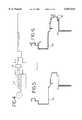
- FIG. 4is a simple diagram of the roll-forming and extrusion process used to create the counterpart to the first section of the window component, as shown in FIG. 3;
- FIG. 5is a cross-sectional view of the counterpart to FIG. 3 after it has been roll-formed (shown along lines 5--5 of FIG. 1);
- FIG. 6is a cross-sectional view of the counterpart to FIG. 3 after a thin layer of ETP has been extruded over it in predetermined functional shapes (shown along lines 6--6 of FIG. 4);
- FIG. 7is a simple diagram of the roller assembly station used to connect the first part of the window component as shown in FIG. 3 with its counterpart as shown in FIG. 6;
- FIG. 8is a cross-sectional view of the resultant window component
- FIG. 9is a cross-sectional view of the window component of FIG. 8 after urethane foam has been injected within its hollow interior and allowed to expand and cure;
- FIG. 10is an exploded view of an embodiment of the present invention shown as a two-sash casement with common frame and corner key assembly, with arrows depicting the flow path of the urethane foam fill as it is injected into the window casement assembly;
- FIG. 11is a top view of the two sash casement with common frame of FIG. 10;
- FIG. 12is an exploded view of a second embodiment of the present invention shown as a sash and corner key assembly, with arrows depicting the flow path of the urethane foam fill as it is injected into the sash assembly;
- FIG. 13is a perspective view of the preferred embodiment of the hollow corner key of FIGS. 11 and 12.
- the present inventionis directed to a process and product for building decorative and structural frame sections for a window, door panel, or other building or architectural construction.
- the processis depicted schematically in FIGS. 1, 4 and 7, with the resultant product being shown in various stages of formation in FIGS. 2, 3, 5, 6 and 8.
- the processincludes the use of roll-formers formers 12 which continuously form the first structural shape 14 from pre-treated metal in flat coil stock form, as shown in FIG. 2.
- the preferred metalis aluminum in flat coil stock, although it is known that other similar type structural metals could also be used.
- cross-head extruders 16which extrude a profile of one-hundredth to six-hundredths of an inch layer of a synthetic material 18, preferably an Extrudable Thermal Plastic (ETP), to both the outside and inside surfaces of the first roll-formed shape 14, as can be seen in FIG. 3.
- ETPExtrudable Thermal Plastic
- An example of an ETP of this natureis GEON, a polyvinyl resin manufactured by the B.F. Goodrich Company.
- FIG. 4is a diagram of a similar process for forming the counterpart structural shape 20 to the first roll-formed structural shape 14 of FIG. 3.
- the counterpart shape 20is roll-formed to form the embodiment of FIG. 5, and then a profile of one-hundredth to six-hundredths of an inch thick layer of ETP 18 is extruded onto the roll-formed shape 20. It is preferred that some areas have thicker layers of ETP applied, as shown in FIG. 6, to improve the dent resistance of the window frame and/or sash.
- some of the ETP 18is extruded onto the roll-formed shape in a functional shape, such as the "C" shaped pockets 22a,b.
- the two shapes 14 and 20are then joined together to form structural member 24, with the "C" shaped pockets 22a,b clipping the first shape 14 together with its counterpart shape 20, as seen in FIG. 8.
- a second function of the "C" shaped pockets 22a,bis that they provide for both a thermal break and a noise break within the structural member 24.
- This process of extruding ETP shapes over roll-formed shapesextends the traditional roll-forming process with the capability of incorporating additional functional shapes onto or into the roll-formed part that either could not be done by roll-forming alone or would be cost prohibitive from a roll-form tooling standpoint.
- Materialcan be located on the interior or exterior of the roll-formed shape to enhance performance and assembly requirements. It also extends traditional PVC extrusion process by allowing dark colors to be used without risk of heat deflection.
- the processhas the further advantage of running between four to eight times faster than traditional extruded PVC shapes. This, combined with utilizing thin roll-forming and ETP materials, allows this process to produce shapes that are approximately the same manufacturing cost of traditional PVC extruded shapes, while incorporating superior mechanical properties.
- the roll-formed/extruded partsAfter the roll-formed/extruded parts leave the roll-coupling station 25 of FIG. 7, they are cut into lineal lengths, approximately sixteen to twenty feet, which are ready to be fabricated into window/structural components. For purposes of the window frame 26 shown in FIG. 11, the lineal lengths are miter-cut to form window frame members 28.
- FIG. 11depicts a two-sash window frame 26.
- the preferred embodimentis illustrated as comprising miter-cut frame members 28 and four hollow injection-molded corner keys 30 that serve to join or couple the assembly together.
- center corner keys 31are also used.
- the partscan be temporarily held together via a small fastener (not shown) which passes through the frame members 28 into and through the wall of the corner key 30.
- small holes 34a,bare drilled mid-point on opposite sides of the window frame 26 (FIG. 11) and window sash 32 (FIG.
- the small holes 34a,bcould be created anywhere along the exterior of the window frame 26 and sash 32.
- Two rubber grommet type devices 36a,bare inserted into holes 34a,b, respectively.
- the first grommet 36ais designed for a filling nozzle (not shown).
- a two-part urethane dispensing machine(also not shown), capable of injecting a precise shot of one to ten pounds of urethane foam 38 (via the filling nozzle which is inserted into the first grommet hole 36a) is used to fill the interior of the window frame 26 (FIG. 11) or sash 32 (FIG. 12).
- First grommet 36aalso functions to keep the urethane foam 38 off of the finished outer surface of the window frame 26 and sash 32.
- the second grommet 36bacts as a vent plug to allow air to escape from hole 34b during the filling process, but retains the urethane foam 38 within the hollow window frame 26 (shown in partial view in FIG. 11) and sash 32 (shown in partial view in FIG. 12).
- the preferred material for the urethane foam 38is an expanded polyurethane-urea polymer comprising inter-reacting polymer isocyanate A, polyether polylol based on sucrose and glycerin initiators components B, polyester diol or polyol components C, chain-extending glycol components D, silicone surfactant component E, water component F and polyurethane catalysts.
- Each componentis present in those relative proportions by weight, as known to one skilled in the art, to produce expanded rigid polyurethane foam with a density of four pounds per cubic foot.
- the water content Fcan be varied to also give densities ranging from 1.5 to 35.0 pounds per cubic foot.
- a chemical foamsuch as the one described is manufactured by Azon USA, Inc. under the product designation 13 302 A.
- a similar type foam, also produced by Azon USA, Inc.is sold under the product designation SUF 200 Series Component B.
- the foam 38is forced under pressure to flow through the entire assembly and expand to fill all of the internal voids of the window frame 26, as shown in FIG. 9.
- the hollow corner keys 30are designed to allow the liquid foam 38 to pass through with minimal restriction.
- the corner key 30is designed so as to closely fit within the structural frame members 28, gaps ranging from five one-thousandths of an inch to ten one-thousandths of an inch still exist between the exterior of the corner key 30 and the interior of the frame member 28. These gaps, which extend along the miter joint area of the structural frame members 28, create voids that impede the flow of the urethane foam 38 around the miter joint. To overcome this impedance, as best shown in FIG. 13, the key 30 has strategic vent holes 40 molded into its outer walls to allow the foam 38 to flow around the outside of the corner key 30, which locks it to the window frame members 28.
- a series of recesses 42which are integrated into the injection-molded corner key 30, allow the foam 38 to flow freely between the outside surfaces of the corner key 30 and the inside surfaces of the window frame members 28 while preventing the foam 38 from escaping through the miter joints of the window frame members 28 to the outside surfaces of the product.
- a secondary groove 46is molded into the corner keys 30 at the miter joint area to allow a caulk, or any similar type adhesive, to be injected through a hole (not shown) at each corner of the window frame 26 and into the secondary groove 46 of the corner key 30. The addition of the caulk bridges the vinyl and aluminum/steel miter cut edges to increase corrosion resistance in coastal applications.
- the window frame 26Once filled with the urethane foam 38, which should take approximately twenty seconds for a four-foot by four-foot frame, the window frame 26 must sit in a square and flat stable condition until the urethane foam 38 cures to a solid. This curing state varies between thirty seconds and thirty minutes, depending on the catalytic reaction built into the foam formulation. After curing is complete, the window frame 26 can be further processed like any other window frame component, i.e., the attachment of hardware as known to one of ordinary skill in the art. The window sash 32 is processed similarly to window frame 26.
- urethane foam 38into the frame 26 and sash 32 serves three distinct functions.
- its primary purposeis as a structural reinforcement.
- the expansion of the foam 38 throughout the hollow interior of the frame 26provides increased resistance to deflection of the roll-formed aluminum/steel caused by strong wind or other similar environmental conditions.
- the compressive tensile strength of the foam 38limits the amount of buckling of the frame walls of the frame members 28. Should deflection of the aluminum occur, the addition of the foam 38 allows for the aluminum to return back to its original position, without any damage to the structure of the frame 26.
- the structural integrity of the frame 26is significantly improved by the urethane foam fill 38.
- the composite frame member 28(without foam filling 38) would act as a thin-walled column or beam.
- the load capacity of such thin-walled sectionsis limited by a buckling mode of failure.
- Thin walled sectionsmay buckle under axial, torsion, or bending loads. The fundamental reason is that the thin walls provide little resistance to lateral deflection.
- Buckling of an un-reinforced sectionwould initiate at some small localized imperfection, such as a dent or scratch. Axial, torsion, or bending loads on the section would cause lateral deflection in the vicinity of the defect and subsequently lead to instability and buckling collapse of the section. Thus, failure may occur at loads well below the yield limit of the section.
- the foam fill 38 within the sectiongreatly reduces the lateral deflections, even if relatively large defects are present.
- Increased lateral rigidity due to the foam fill 38greatly reduces the tendency for buckling failure and thereby the load capacity of the frame members 28 are substantially increased.
- the injected foam 38may fill in gaps between parts such as might occur to slight mismatch or misalignment of mating surfaces. As a result, load transfer between mating parts is more evenly distributed across the cross section of the frame 26. Uniform loading reduces the tendency for buckling failure and thus increases the load capacity of the frame members 28.
- the foam 38acts as a sealant. As the foam 38 cures, it adheres the various pieces 28 and 30 of the frame 26 together, thereby locking them in position.
- the foam 38also acts as insulation against the thermal transfer of heat through the frame members 28.
- a combination of the two functional shapes 14 and 20 joined to form the structural member 24 having both a thermal and noise break, plus the layer of ETP 18 extruded on both the inside and outside surfaces of the functional shapes 14 and 20, plus the addition of the urethane foam 38 within the resultant frame member 28,provides an excellent sound barrier.
- vent holes 40 in the corner keys 30facilitate complete filling of the recessed regions 42 of the corner keys 30.
- a particular difficulty of filling the recesses 42, in the absence of vent holes 40,is that the flow diverges into the recesses 42 immediately following an expansion of the flow (and thus a pressure drop in the flow stream) from the main cavity of the corner keys 30 into the main cavity of the extruded frame members 28. This is followed by a one hundred eighty degree turn into a long narrow flow path into the recesses 42.
- the vent holes 40are more favorably located in the narrower (higher pressure) section of flow stream.
- vent holes 40may be centrally located within the recesses 42 and thereby reduce the length of the flow path within the narrow recess 42.
- a principal advantage of filling the recessed area 42 of the corner keys 30 through the vent holes 40is that it provides the ability to adjust the flow into the recesses 42 without changing the design of the recesses 42 themselves.
- the geometry of the recesses 42may thus be designed for optimum functionality in terms of the adhesion and locking capability.
- the flow into the recesses 42can be separately controlled by the design of the vent holes 40. Flow into the recesses 42 is influenced by changing any of the following: the number and location of the vent hole(s) 40, the size of the vent hole(s) 40, and the geometry of the vent holes 40 (e.g., round versus rectangular, radius edges versus sharp edges).
Landscapes
- Engineering & Computer Science (AREA)
- Civil Engineering (AREA)
- Structural Engineering (AREA)
- Wing Frames And Configurations (AREA)
Abstract
Description
Claims (18)
Priority Applications (2)
| Application Number | Priority Date | Filing Date | Title |
|---|---|---|---|
| US09/148,516US6047514A (en) | 1998-09-04 | 1998-09-04 | Window component and method of manufacture |
| US09/375,098US6073412A (en) | 1998-09-04 | 1999-08-16 | Corner key for window component assembly |
Applications Claiming Priority (1)
| Application Number | Priority Date | Filing Date | Title |
|---|---|---|---|
| US09/148,516US6047514A (en) | 1998-09-04 | 1998-09-04 | Window component and method of manufacture |
Related Child Applications (1)
| Application Number | Title | Priority Date | Filing Date |
|---|---|---|---|
| US09/375,098DivisionUS6073412A (en) | 1998-09-04 | 1999-08-16 | Corner key for window component assembly |
Publications (1)
| Publication Number | Publication Date |
|---|---|
| US6047514Atrue US6047514A (en) | 2000-04-11 |
Family
ID=22526106
Family Applications (2)
| Application Number | Title | Priority Date | Filing Date |
|---|---|---|---|
| US09/148,516Expired - Fee RelatedUS6047514A (en) | 1998-09-04 | 1998-09-04 | Window component and method of manufacture |
| US09/375,098Expired - Fee RelatedUS6073412A (en) | 1998-09-04 | 1999-08-16 | Corner key for window component assembly |
Family Applications After (1)
| Application Number | Title | Priority Date | Filing Date |
|---|---|---|---|
| US09/375,098Expired - Fee RelatedUS6073412A (en) | 1998-09-04 | 1999-08-16 | Corner key for window component assembly |
Country Status (1)
| Country | Link |
|---|---|
| US (2) | US6047514A (en) |
Cited By (53)
| Publication number | Priority date | Publication date | Assignee | Title |
|---|---|---|---|---|
| US6347494B1 (en)* | 1999-03-12 | 2002-02-19 | Cw Ohio, Inc. | Wood filled plastic building members and method of manufacture |
| GB2372775A (en)* | 2001-02-23 | 2002-09-04 | Lb Plastics Ltd | A coating for a window or door frame reinforcing member |
| GR20010100316A (en)* | 2001-07-03 | 2003-03-28 | Φιλωτα Μοδεστος Καλεργης | Method of construction of a decorative surface of rail elements from an aluminium or brass sheet |
| US20030229980A1 (en)* | 2000-10-03 | 2003-12-18 | Lasusa Frank | Method and process of a universal window system using singular advanced components of a polymer based or metallurgy based product |
| US6678934B1 (en)* | 1999-10-04 | 2004-01-20 | Lasusa Frank | Method and process of a universal window system using singular advanced components of a polymer based or metallurgy based product |
| US20040083678A1 (en)* | 2002-11-01 | 2004-05-06 | Tumlin Ricky W. | Molded snap-together frame |
| US6746175B1 (en)* | 1999-10-05 | 2004-06-08 | Pella Corporation | Fenestration corner lock |
| US20040123536A1 (en)* | 2002-12-27 | 2004-07-01 | Han-Sen Lee | Window frame molding system |
| US20050028480A1 (en)* | 1999-10-04 | 2005-02-10 | Lasusa Frank | Reinforcing structure for a window frame system |
| US20050115178A1 (en)* | 2002-01-14 | 2005-06-02 | Helmut Schmidt | Corner key for connecting profiles together and frame work assembly |
| US20050144861A1 (en)* | 2003-03-27 | 2005-07-07 | Gabriel Petta | Frame assembly for windows or doors |
| US20050223661A1 (en)* | 2004-03-04 | 2005-10-13 | Hetherington Richard W | Corner key with pathway |
| US20060059780A1 (en)* | 2004-09-20 | 2006-03-23 | Gabriel Petta | Frame assembly for window with vertically sliding sash |
| USD537538S1 (en)* | 2005-04-12 | 2007-02-27 | Mikron Industries, Inc. | Window component extrusion |
| USD537542S1 (en)* | 2005-10-28 | 2007-02-27 | Certainteed Corp. | Sill nose for vinyl window having wood-like appearance |
| GB2434395A (en)* | 2006-08-08 | 2007-07-25 | Bowater Building Products Ltd | Frame member with insulating portion |
| US20070175039A1 (en)* | 1999-10-04 | 2007-08-02 | Lasusa Frank | Window component notching system and method |
| US20080034702A1 (en)* | 2004-03-04 | 2008-02-14 | Ray Garries | Corner key with pathway |
| USD602605S1 (en)* | 2008-07-31 | 2009-10-20 | Mikron Industries, Inc. | Window component extrusion |
| USD602606S1 (en)* | 2008-07-31 | 2009-10-20 | Mikron Industries, Inc. | Window component extrusion |
| USD602608S1 (en)* | 2008-07-31 | 2009-10-20 | Mikron Industries, Inc. | Window component extrusion |
| US20090282761A1 (en)* | 2008-05-16 | 2009-11-19 | Remi Perron | Structural Element for the Construction of Log Type Houses |
| US7634880B2 (en) | 2006-03-17 | 2009-12-22 | Milgard Manufacturing, Inc. | Foam seal frame corner joint and method of manufacture |
| US20100064630A1 (en)* | 2006-05-18 | 2010-03-18 | Williams Donald S | Pultruded utility support structures |
| US20100269433A1 (en)* | 2008-08-21 | 2010-10-28 | Gregory Westra | Buck system |
| US20110011006A1 (en)* | 2009-07-16 | 2011-01-20 | Aluplast Gmbh | Method for the production of an insulated window or door frame |
| EP2072743A3 (en)* | 2007-12-21 | 2011-04-13 | Aluplast Gmbh | Method for foaming a hollow window or door frame |
| US20110134653A1 (en)* | 2006-05-18 | 2011-06-09 | Duratel, Llc | Pultruded/extruded utility lighting, mounting and climbing structures |
| US20110135423A1 (en)* | 2006-05-18 | 2011-06-09 | Duratel, Llc | Apparatus for transporting and raising pultruded/extruded utility support structures |
| US8024908B2 (en) | 2006-05-18 | 2011-09-27 | Williams Donald S | Pultruded utility structures |
| US8028489B1 (en)* | 2010-01-07 | 2011-10-04 | Lawrence Barry G | Framed window screen and connector |
| US20110265408A1 (en)* | 2010-04-28 | 2011-11-03 | Roshan Kumar Jha | Thermally insulated structural members, and doors and windows incorporating them |
| US8474221B1 (en) | 2012-01-20 | 2013-07-02 | Trident Industries, LLC | Telescoping fiberglass utility pole |
| US8596017B2 (en)* | 2011-11-03 | 2013-12-03 | James Hardie Technology Limited | Frame members, corner key and assembly method |
| US8857129B2 (en) | 2011-11-03 | 2014-10-14 | Proformance Maufacturing, Inc. | Frame assembly having a corner key |
| USD720083S1 (en)* | 2010-04-30 | 2014-12-23 | Mikron Industries, Inc. | Window component extrusion |
| CN105268863A (en)* | 2015-09-29 | 2016-01-27 | 江苏金源锻造股份有限公司 | Technological method for design of anti-theft door frame mold |
| USD767788S1 (en)* | 2015-03-11 | 2016-09-27 | Deceuninck North America, Llc | Window frame extrusion |
| USD767792S1 (en)* | 2015-03-11 | 2016-09-27 | Deceuninck North America, Llc | Window frame extrusion |
| USD767789S1 (en)* | 2015-03-11 | 2016-09-27 | Deceuninck North America, Llc | Window frame extrusion |
| CN106446623A (en)* | 2015-08-05 | 2017-02-22 | 江苏金源锻造股份有限公司 | Mould design process method |
| EP3309340A1 (en)* | 2016-10-13 | 2018-04-18 | VKR Holding A/S | A frame member, a method for making a frame member, a frame structure and use of a frame member |
| RU191442U1 (en)* | 2019-03-05 | 2019-08-06 | Акционерное общество "Виталон" | HEAT-INSULATED LIGHT-TRANSPARENT FENCING OF OPENING |
| WO2019164998A1 (en)* | 2018-02-20 | 2019-08-29 | Fiber Composites, LLC (dba Fiberon) | Corner key composite member |
| US11187029B1 (en) | 2019-01-31 | 2021-11-30 | Andersen Corporation | Flexible drip cap |
| US11585149B2 (en) | 2019-07-12 | 2023-02-21 | Jeld-Wen, Inc. | Systems and methods for joining fenestration frame members |
| US11643863B2 (en) | 2019-10-28 | 2023-05-09 | Pella Corporation | Integrated sash assembly |
| USD1009306S1 (en) | 2021-05-18 | 2023-12-26 | Jeld-Wen, Inc. | Corner key |
| USD1009307S1 (en) | 2021-05-18 | 2023-12-26 | Jeld-Wen, Inc. | Corner key |
| USD1009308S1 (en) | 2021-05-18 | 2023-12-26 | Jeld-Wen, Inc. | Corner key |
| USD1009305S1 (en) | 2021-05-18 | 2023-12-26 | Jeld-Wen, Inc. | Corner key |
| US12013172B2 (en)* | 2015-07-15 | 2024-06-18 | Lg Electronics Inc. | Door for home appliance, home appliance, and method for manufacturing the same |
| US20240200393A1 (en)* | 2021-04-12 | 2024-06-20 | Vkr Holding A/S | A building aperture window comprising wood fibre insulation |
Families Citing this family (16)
| Publication number | Priority date | Publication date | Assignee | Title |
|---|---|---|---|---|
| GB0114254D0 (en)* | 2001-06-12 | 2001-08-01 | Burnden Group The Plc | Improvements in and relating to consevatory roof structures and glazing bars therefor |
| KR200301544Y1 (en)* | 2002-10-10 | 2003-01-29 | 주식회사 케이비엠퍼니쳐 | Assembly for box |
| US20050016075A1 (en)* | 2003-07-22 | 2005-01-27 | Germanus Kong | Insect barrier |
| US20060254174A1 (en)* | 2004-12-07 | 2006-11-16 | Chen Chang T | Door panel having reinforcing structure |
| US7669380B2 (en)* | 2005-01-06 | 2010-03-02 | Tapco International Corporation | Glue manifold for a functional shutter |
| US7600355B1 (en)* | 2006-01-23 | 2009-10-13 | Klein Robert D | Unitary molded corner piece method and apparatus |
| US20080297015A1 (en) | 2007-05-30 | 2008-12-04 | Steelcase Inc. | Storage unit back stop and method |
| US8652382B2 (en) | 2008-07-01 | 2014-02-18 | Andersen Corporation | Methods of joining |
| US20100154329A1 (en)* | 2008-12-24 | 2010-06-24 | Adkins Herbert S | Window assembly including sealant blocks |
| MX343635B (en)* | 2009-12-02 | 2016-11-15 | Nippon Steel & Sumitomo Metal Corp | Structure. |
| US8826612B2 (en)* | 2010-06-03 | 2014-09-09 | Perfect Window Reveal, Llc | Window reveal systems and methods |
| USD673300S1 (en)* | 2011-06-10 | 2012-12-25 | S.I.L. Plastic Sales & Supplies Inc. | Casing corner piece |
| AU2013314995B2 (en) | 2012-09-17 | 2017-12-07 | Steelcase Inc. | Floor-to-ceiling partition wall assembly |
| USD756536S1 (en)* | 2014-08-05 | 2016-05-17 | Home Improvement Systems, Inc. | Plinth for window screen installation system |
| US10077598B2 (en) | 2015-08-28 | 2018-09-18 | Sierra Pacific Industries | Versatile hybrid window system |
| CN105332594A (en)* | 2015-11-27 | 2016-02-17 | 赵永兴 | Energy-saving type spicing device for window auxiliary frame |
Citations (21)
| Publication number | Priority date | Publication date | Assignee | Title |
|---|---|---|---|---|
| US2131115A (en)* | 1935-08-07 | 1938-09-27 | Harry E Naisuler | Framework construction |
| US3137744A (en)* | 1961-09-19 | 1964-06-16 | Gen Motors Corp | Refrigerating apparatus |
| US3402520A (en)* | 1966-12-23 | 1968-09-24 | Home Comfort Products Co | Panel with foamed-in-place core |
| US3562886A (en)* | 1969-01-17 | 1971-02-16 | Bailey Co Inc | Method of making a framing member |
| US3703063A (en)* | 1969-04-22 | 1972-11-21 | Dynamit Nobel Ag | Profile member for windows, doors, facades, or the like |
| US3827207A (en)* | 1972-11-30 | 1974-08-06 | Aro Plastics Dev Ltd | Composite frame member with bushed aperture |
| US3885371A (en)* | 1971-03-01 | 1975-05-27 | Bridgewater Martin | Architectural frames |
| US3934384A (en)* | 1974-01-07 | 1976-01-27 | H. H. Robertson Company | Closure seal member and fixed frame assembly utilizing the same |
| US3964231A (en)* | 1972-11-29 | 1976-06-22 | Dynamit Nobel Aktiengesellschaft | Plastic-encased metallic hollow profile member |
| US4067163A (en)* | 1977-03-11 | 1978-01-10 | Hetman Frank W | Thermally insulated and connected window frame members and the method of making the same |
| US4240765A (en)* | 1979-04-27 | 1980-12-23 | Offterdinger Hermann F | Corner construction |
| US4296587A (en)* | 1979-07-31 | 1981-10-27 | Custom Rollforming Company Limited | Spacer for double glazed windows incorporating interlock means |
| US4342144A (en)* | 1979-10-22 | 1982-08-03 | Yoshida Kogyo K.K. | Method of manufacturing a thermally insulating sash bar |
| US4520602A (en)* | 1981-08-03 | 1985-06-04 | Thermetic Glass, Inc. | Multi-pane sealed window and method for forming same |
| US4570406A (en)* | 1983-12-12 | 1986-02-18 | Acorn Building Components, Inc. | Screen frame corner connector key |
| US4651482A (en)* | 1985-04-10 | 1987-03-24 | Ryszard Borys | Corner construction for prefabricated spacer for multiple-glazed windows |
| US4702051A (en)* | 1984-04-30 | 1987-10-27 | Miller Clarence W | Size-adjustable window insert assembly |
| US4841696A (en)* | 1984-04-30 | 1989-06-27 | Thomas J. Kupensky | Size-adjustable window insert assembly |
| US4860512A (en)* | 1988-06-15 | 1989-08-29 | Therma-Tru Corp. | Compression molded door assembly |
| US5345678A (en)* | 1991-12-20 | 1994-09-13 | Termofrost Ab | Method of assembling window and glass-door casements |
| US5379518A (en)* | 1993-02-04 | 1995-01-10 | Caradon America Inc. | Method of producing a window sash |
Family Cites Families (5)
| Publication number | Priority date | Publication date | Assignee | Title |
|---|---|---|---|---|
| US2661822A (en)* | 1950-06-10 | 1953-12-08 | Wisco Inc | Door corner |
| US2984447A (en)* | 1952-10-22 | 1961-05-16 | Square D Co | Wiring duct hanger |
| US2861659A (en)* | 1956-12-10 | 1958-11-25 | Adlake Co | Corner joint |
| US4453855A (en)* | 1981-08-03 | 1984-06-12 | Thermetic Glass, Inc. | Corner construction for spacer used in multi-pane windows |
| US4862612A (en)* | 1986-11-27 | 1989-09-05 | Yoshichika Sugihara | Frame |
- 1998
- 1998-09-04USUS09/148,516patent/US6047514A/ennot_activeExpired - Fee Related
- 1999
- 1999-08-16USUS09/375,098patent/US6073412A/ennot_activeExpired - Fee Related
Patent Citations (21)
| Publication number | Priority date | Publication date | Assignee | Title |
|---|---|---|---|---|
| US2131115A (en)* | 1935-08-07 | 1938-09-27 | Harry E Naisuler | Framework construction |
| US3137744A (en)* | 1961-09-19 | 1964-06-16 | Gen Motors Corp | Refrigerating apparatus |
| US3402520A (en)* | 1966-12-23 | 1968-09-24 | Home Comfort Products Co | Panel with foamed-in-place core |
| US3562886A (en)* | 1969-01-17 | 1971-02-16 | Bailey Co Inc | Method of making a framing member |
| US3703063A (en)* | 1969-04-22 | 1972-11-21 | Dynamit Nobel Ag | Profile member for windows, doors, facades, or the like |
| US3885371A (en)* | 1971-03-01 | 1975-05-27 | Bridgewater Martin | Architectural frames |
| US3964231A (en)* | 1972-11-29 | 1976-06-22 | Dynamit Nobel Aktiengesellschaft | Plastic-encased metallic hollow profile member |
| US3827207A (en)* | 1972-11-30 | 1974-08-06 | Aro Plastics Dev Ltd | Composite frame member with bushed aperture |
| US3934384A (en)* | 1974-01-07 | 1976-01-27 | H. H. Robertson Company | Closure seal member and fixed frame assembly utilizing the same |
| US4067163A (en)* | 1977-03-11 | 1978-01-10 | Hetman Frank W | Thermally insulated and connected window frame members and the method of making the same |
| US4240765A (en)* | 1979-04-27 | 1980-12-23 | Offterdinger Hermann F | Corner construction |
| US4296587A (en)* | 1979-07-31 | 1981-10-27 | Custom Rollforming Company Limited | Spacer for double glazed windows incorporating interlock means |
| US4342144A (en)* | 1979-10-22 | 1982-08-03 | Yoshida Kogyo K.K. | Method of manufacturing a thermally insulating sash bar |
| US4520602A (en)* | 1981-08-03 | 1985-06-04 | Thermetic Glass, Inc. | Multi-pane sealed window and method for forming same |
| US4570406A (en)* | 1983-12-12 | 1986-02-18 | Acorn Building Components, Inc. | Screen frame corner connector key |
| US4702051A (en)* | 1984-04-30 | 1987-10-27 | Miller Clarence W | Size-adjustable window insert assembly |
| US4841696A (en)* | 1984-04-30 | 1989-06-27 | Thomas J. Kupensky | Size-adjustable window insert assembly |
| US4651482A (en)* | 1985-04-10 | 1987-03-24 | Ryszard Borys | Corner construction for prefabricated spacer for multiple-glazed windows |
| US4860512A (en)* | 1988-06-15 | 1989-08-29 | Therma-Tru Corp. | Compression molded door assembly |
| US5345678A (en)* | 1991-12-20 | 1994-09-13 | Termofrost Ab | Method of assembling window and glass-door casements |
| US5379518A (en)* | 1993-02-04 | 1995-01-10 | Caradon America Inc. | Method of producing a window sash |
Cited By (71)
| Publication number | Priority date | Publication date | Assignee | Title |
|---|---|---|---|---|
| US6347494B1 (en)* | 1999-03-12 | 2002-02-19 | Cw Ohio, Inc. | Wood filled plastic building members and method of manufacture |
| US20070175039A1 (en)* | 1999-10-04 | 2007-08-02 | Lasusa Frank | Window component notching system and method |
| US20050028480A1 (en)* | 1999-10-04 | 2005-02-10 | Lasusa Frank | Reinforcing structure for a window frame system |
| US7546793B2 (en) | 1999-10-04 | 2009-06-16 | Lasusa Frank | Window component notching system and method |
| US6678934B1 (en)* | 1999-10-04 | 2004-01-20 | Lasusa Frank | Method and process of a universal window system using singular advanced components of a polymer based or metallurgy based product |
| US6746175B1 (en)* | 1999-10-05 | 2004-06-08 | Pella Corporation | Fenestration corner lock |
| US20030229980A1 (en)* | 2000-10-03 | 2003-12-18 | Lasusa Frank | Method and process of a universal window system using singular advanced components of a polymer based or metallurgy based product |
| US7117576B2 (en) | 2000-10-03 | 2006-10-10 | Vinyllink, Llc | Method and process of a universal window system using singular advanced components of a polymer based or metallurgy based product |
| GB2372775B (en)* | 2001-02-23 | 2004-01-07 | Lb Plastics Ltd | Window and door frames |
| GB2372775A (en)* | 2001-02-23 | 2002-09-04 | Lb Plastics Ltd | A coating for a window or door frame reinforcing member |
| GR20010100316A (en)* | 2001-07-03 | 2003-03-28 | Φιλωτα Μοδεστος Καλεργης | Method of construction of a decorative surface of rail elements from an aluminium or brass sheet |
| US20050115178A1 (en)* | 2002-01-14 | 2005-06-02 | Helmut Schmidt | Corner key for connecting profiles together and frame work assembly |
| US20040083678A1 (en)* | 2002-11-01 | 2004-05-06 | Tumlin Ricky W. | Molded snap-together frame |
| US7010888B2 (en) | 2002-11-01 | 2006-03-14 | L.L. Culmat, L.P. | Molded snap-together frame |
| US20040123536A1 (en)* | 2002-12-27 | 2004-07-01 | Han-Sen Lee | Window frame molding system |
| US6807783B2 (en)* | 2002-12-27 | 2004-10-26 | Han-Sen Lee | Window frame molding system |
| US7707778B2 (en) | 2003-03-27 | 2010-05-04 | Alpa Lumber Inc. | Frame assembly for windows or doors with removable sash |
| US20050144861A1 (en)* | 2003-03-27 | 2005-07-07 | Gabriel Petta | Frame assembly for windows or doors |
| US7614188B2 (en)* | 2004-03-04 | 2009-11-10 | Jeld-Wen, Inc. | Corner key with pathway |
| US20050223661A1 (en)* | 2004-03-04 | 2005-10-13 | Hetherington Richard W | Corner key with pathway |
| US20080034702A1 (en)* | 2004-03-04 | 2008-02-14 | Ray Garries | Corner key with pathway |
| US7707779B2 (en) | 2004-09-20 | 2010-05-04 | Alpa Lumber Inc. | Frame assembly for window with vertically sliding sash |
| US20060059780A1 (en)* | 2004-09-20 | 2006-03-23 | Gabriel Petta | Frame assembly for window with vertically sliding sash |
| USD537538S1 (en)* | 2005-04-12 | 2007-02-27 | Mikron Industries, Inc. | Window component extrusion |
| USD537542S1 (en)* | 2005-10-28 | 2007-02-27 | Certainteed Corp. | Sill nose for vinyl window having wood-like appearance |
| US7634880B2 (en) | 2006-03-17 | 2009-12-22 | Milgard Manufacturing, Inc. | Foam seal frame corner joint and method of manufacture |
| US20110135423A1 (en)* | 2006-05-18 | 2011-06-09 | Duratel, Llc | Apparatus for transporting and raising pultruded/extruded utility support structures |
| US8024908B2 (en) | 2006-05-18 | 2011-09-27 | Williams Donald S | Pultruded utility structures |
| US8322105B2 (en) | 2006-05-18 | 2012-12-04 | Duratel, Llc | Pultruded utility support structures |
| US20100064630A1 (en)* | 2006-05-18 | 2010-03-18 | Williams Donald S | Pultruded utility support structures |
| US8359814B2 (en) | 2006-05-18 | 2013-01-29 | Duratel, Inc. | Pultruded/extruded utility lighting, mounting and climbing structures |
| US20110134653A1 (en)* | 2006-05-18 | 2011-06-09 | Duratel, Llc | Pultruded/extruded utility lighting, mounting and climbing structures |
| GB2434395A (en)* | 2006-08-08 | 2007-07-25 | Bowater Building Products Ltd | Frame member with insulating portion |
| GB2434395B (en)* | 2006-08-08 | 2011-03-09 | Bowater Building Products Ltd | A frame member for a window frame and a window frame comprising such a frame member |
| EP2072743A3 (en)* | 2007-12-21 | 2011-04-13 | Aluplast Gmbh | Method for foaming a hollow window or door frame |
| US20090282761A1 (en)* | 2008-05-16 | 2009-11-19 | Remi Perron | Structural Element for the Construction of Log Type Houses |
| USD602605S1 (en)* | 2008-07-31 | 2009-10-20 | Mikron Industries, Inc. | Window component extrusion |
| USD602608S1 (en)* | 2008-07-31 | 2009-10-20 | Mikron Industries, Inc. | Window component extrusion |
| USD602606S1 (en)* | 2008-07-31 | 2009-10-20 | Mikron Industries, Inc. | Window component extrusion |
| US20100269433A1 (en)* | 2008-08-21 | 2010-10-28 | Gregory Westra | Buck system |
| US20110011006A1 (en)* | 2009-07-16 | 2011-01-20 | Aluplast Gmbh | Method for the production of an insulated window or door frame |
| US8028489B1 (en)* | 2010-01-07 | 2011-10-04 | Lawrence Barry G | Framed window screen and connector |
| US8617702B2 (en)* | 2010-04-28 | 2013-12-31 | Sabic Innovative Plastics Ip B.V. | Thermally insulated structural members, and doors and windows incorporating them |
| US20110265408A1 (en)* | 2010-04-28 | 2011-11-03 | Roshan Kumar Jha | Thermally insulated structural members, and doors and windows incorporating them |
| USD720083S1 (en)* | 2010-04-30 | 2014-12-23 | Mikron Industries, Inc. | Window component extrusion |
| US8596017B2 (en)* | 2011-11-03 | 2013-12-03 | James Hardie Technology Limited | Frame members, corner key and assembly method |
| US8683694B1 (en) | 2011-11-03 | 2014-04-01 | James Hardie Technology Limited | Method of forming a frame assembly |
| US8857129B2 (en) | 2011-11-03 | 2014-10-14 | Proformance Maufacturing, Inc. | Frame assembly having a corner key |
| US8474221B1 (en) | 2012-01-20 | 2013-07-02 | Trident Industries, LLC | Telescoping fiberglass utility pole |
| USD767789S1 (en)* | 2015-03-11 | 2016-09-27 | Deceuninck North America, Llc | Window frame extrusion |
| USD767788S1 (en)* | 2015-03-11 | 2016-09-27 | Deceuninck North America, Llc | Window frame extrusion |
| USD767792S1 (en)* | 2015-03-11 | 2016-09-27 | Deceuninck North America, Llc | Window frame extrusion |
| US12298057B2 (en)* | 2015-07-15 | 2025-05-13 | Lg Electronics Inc. | Door for home appliance, home appliance, and method for manufacturing the same |
| US12013172B2 (en)* | 2015-07-15 | 2024-06-18 | Lg Electronics Inc. | Door for home appliance, home appliance, and method for manufacturing the same |
| EP4421426A3 (en)* | 2015-07-15 | 2024-10-30 | LG Electronics Inc. | Door for home appliance, home appliance, and method for manufacturing the same |
| EP3827957B1 (en)* | 2015-07-15 | 2024-09-04 | LG Electronics Inc. | Refrigerator |
| CN106446623A (en)* | 2015-08-05 | 2017-02-22 | 江苏金源锻造股份有限公司 | Mould design process method |
| CN105268863A (en)* | 2015-09-29 | 2016-01-27 | 江苏金源锻造股份有限公司 | Technological method for design of anti-theft door frame mold |
| EP3309340A1 (en)* | 2016-10-13 | 2018-04-18 | VKR Holding A/S | A frame member, a method for making a frame member, a frame structure and use of a frame member |
| DK201670806A1 (en)* | 2016-10-13 | 2018-04-23 | Vkr Holding As | A frame member, a method for making a frame member, a frame structure and use of a frame member |
| US10890027B2 (en) | 2018-02-20 | 2021-01-12 | Fiber Composites, Llc | Corner key composite member |
| WO2019164998A1 (en)* | 2018-02-20 | 2019-08-29 | Fiber Composites, LLC (dba Fiberon) | Corner key composite member |
| US11187029B1 (en) | 2019-01-31 | 2021-11-30 | Andersen Corporation | Flexible drip cap |
| RU191442U1 (en)* | 2019-03-05 | 2019-08-06 | Акционерное общество "Виталон" | HEAT-INSULATED LIGHT-TRANSPARENT FENCING OF OPENING |
| US11585149B2 (en) | 2019-07-12 | 2023-02-21 | Jeld-Wen, Inc. | Systems and methods for joining fenestration frame members |
| US11643863B2 (en) | 2019-10-28 | 2023-05-09 | Pella Corporation | Integrated sash assembly |
| US20240200393A1 (en)* | 2021-04-12 | 2024-06-20 | Vkr Holding A/S | A building aperture window comprising wood fibre insulation |
| USD1009305S1 (en) | 2021-05-18 | 2023-12-26 | Jeld-Wen, Inc. | Corner key |
| USD1009308S1 (en) | 2021-05-18 | 2023-12-26 | Jeld-Wen, Inc. | Corner key |
| USD1009307S1 (en) | 2021-05-18 | 2023-12-26 | Jeld-Wen, Inc. | Corner key |
| USD1009306S1 (en) | 2021-05-18 | 2023-12-26 | Jeld-Wen, Inc. | Corner key |
Also Published As
| Publication number | Publication date |
|---|---|
| US6073412A (en) | 2000-06-13 |
Similar Documents
| Publication | Publication Date | Title |
|---|---|---|
| US6047514A (en) | Window component and method of manufacture | |
| US5858287A (en) | Extrusion method of producing a polymeric sealing/spring strip | |
| EP0865559B1 (en) | Window or door made from a core consisting of foam-containing sections | |
| US6003277A (en) | Co-extruded integrally reinforced cellular PVC window sash | |
| CA2794488C (en) | Frame members, corner key and assembly method | |
| US8857129B2 (en) | Frame assembly having a corner key | |
| AT511180B1 (en) | Profile element made of plastic | |
| CA2140162A1 (en) | Modular anti-warping door structure | |
| EP1019607B1 (en) | Frame profiles for producing window or door frames and a method for producing the same | |
| EP2642060B1 (en) | Window or door leaves | |
| US3885371A (en) | Architectural frames | |
| WO1998019036A1 (en) | Heat-insulating spacer for insulating glazing | |
| GB2320048A (en) | Hollow extruded plastics frame filled with settable foam | |
| DE2035808A1 (en) | One-piece frame structures - moulded in duroplast rigid foam with closed cell and sealed skin | |
| US20050028480A1 (en) | Reinforcing structure for a window frame system | |
| CA2296157C (en) | Patio door with integral glazing frame | |
| KR102371814B1 (en) | Aluminum Window frame | |
| DE19605125A1 (en) | Flexible seal for door or window | |
| EP3591160A1 (en) | A window frame adapted for use as a sash or a stationary frame, and a method for making a window frame | |
| CN110792362A (en) | Integral filling type door and window frame and manufacturing method thereof | |
| EP4202168B1 (en) | Window or door leaf and window or door comprising same | |
| EP4202169B1 (en) | Window or door leaf and window or door comprising same | |
| WO2004065742A2 (en) | Part foam components | |
| US20250019966A1 (en) | Manufacturing and Assembly of Fiber Reinforced Polymer Building Systems | |
| CN119843962A (en) | External aluminum high-strength heat-insulation combined door and window and manufacturing method thereof |
Legal Events
| Date | Code | Title | Description |
|---|---|---|---|
| AS | Assignment | Owner name:QUANEX CORPORATION, TEXAS Free format text:ASSIGNMENT OF ASSIGNORS INTEREST;ASSIGNOR:VERCH, JACK T.;REEL/FRAME:009435/0771 Effective date:19980902 | |
| AS | Assignment | Owner name:COMERICA BANK, AS AGENT, MICHIGAN Free format text:SECURITY INTEREST;ASSIGNOR:QUANEX CORPORATION;REEL/FRAME:013782/0001 Effective date:20021126 | |
| REMI | Maintenance fee reminder mailed | ||
| LAPS | Lapse for failure to pay maintenance fees | ||
| FP | Lapsed due to failure to pay maintenance fee | Effective date:20040411 | |
| AS | Assignment | Owner name:WELLS FARGO BANK NATIONAL ASSOCIATION, AS AGENT, T Free format text:SECURITY AGREEMENT;ASSIGNORS:QUANEX BUILDING PRODUCTS CORPORATION;WII HOLDING, INC.;QUANEX SCREENS LLC;AND OTHERS;REEL/FRAME:037045/0227 Effective date:20151102 | |
| AS | Assignment | Owner name:WELLS FARGO BANK, NATIONAL ASSOCIATION, AS ADMINIS Free format text:SECURITY INTEREST;ASSIGNOR:QUANEX BUILDING PRODUCTS CORPORATION;REEL/FRAME:037008/0967 Effective date:20151102 | |
| AS | Assignment | Owner name:QUANEX CORPORATION, TEXAS Free format text:RELEASE BY SECURED PARTY;ASSIGNOR:COMERICA BANK;REEL/FRAME:037032/0957 Effective date:20151112 | |
| AS | Assignment | Owner name:QUANEX HOMESHIELD, LLC, WISCONSIN Free format text:NUNC PRO TUNC ASSIGNMENT;ASSIGNOR:QUANEX CORPORATION;REEL/FRAME:038720/0771 Effective date:20160524 | |
| AS | Assignment | Owner name:WELLS FARGO BANK, NATIONAL ASSOCIATION, AS ADMINIS Free format text:SECURITY INTEREST;ASSIGNOR:QUANEX HOMESHIELD LLC;REEL/FRAME:038736/0125 Effective date:20160525 | |
| AS | Assignment | Owner name:QUANEX HOMESHIELD LLC, MINNESOTA Free format text:RELEASE BY SECURED PARTY;ASSIGNOR:WELLS FARGO BANK, NATIONAL ASSOCIATION, AS ADMINISTRATIVE AGENT;REEL/FRAME:039968/0802 Effective date:20160729 Owner name:QUANEX BUILDING PRODUCTS CORPORATION, TEXAS Free format text:RELEASE BY SECURED PARTY;ASSIGNOR:WELLS FARGO BANK, NATIONAL ASSOCIATION, AS ADMINISTRATIVE AGENT;REEL/FRAME:039968/0657 Effective date:20160729 | |
| AS | Assignment | Owner name:MIKRON INDUSTRIES, INC., KENTUCKY Free format text:RELEASE BY SECURED PARTY;ASSIGNOR:WELLS FARGO BANK, NATIONAL ASSOCIATION, AS AGENT;REEL/FRAME:040293/0152 Effective date:20160729 Owner name:EDGETECH HOLDING CO., OHIO Free format text:RELEASE BY SECURED PARTY;ASSIGNOR:WELLS FARGO BANK, NATIONAL ASSOCIATION, AS AGENT;REEL/FRAME:040293/0152 Effective date:20160729 Owner name:MIKRON WASHINGTON LLC, KENTUCKY Free format text:RELEASE BY SECURED PARTY;ASSIGNOR:WELLS FARGO BANK, NATIONAL ASSOCIATION, AS AGENT;REEL/FRAME:040293/0152 Effective date:20160729 Owner name:BRENTWOOD ACQUISITION CORP., OREGON Free format text:RELEASE BY SECURED PARTY;ASSIGNOR:WELLS FARGO BANK, NATIONAL ASSOCIATION, AS AGENT;REEL/FRAME:040293/0152 Effective date:20160729 Owner name:WII COMPONENTS, INC., MINNESOTA Free format text:RELEASE BY SECURED PARTY;ASSIGNOR:WELLS FARGO BANK, NATIONAL ASSOCIATION, AS AGENT;REEL/FRAME:040293/0152 Effective date:20160729 Owner name:QUANEX BUILDING PRODUCTS CORPORATION, TEXAS Free format text:RELEASE BY SECURED PARTY;ASSIGNOR:WELLS FARGO BANK, NATIONAL ASSOCIATION, AS AGENT;REEL/FRAME:040293/0152 Effective date:20160729 Owner name:PRIMEWOOD, INC., NORTH DAKOTA Free format text:RELEASE BY SECURED PARTY;ASSIGNOR:WELLS FARGO BANK, NATIONAL ASSOCIATION, AS AGENT;REEL/FRAME:040293/0152 Effective date:20160729 Owner name:WII HOLDING, INC., MINNESOTA Free format text:RELEASE BY SECURED PARTY;ASSIGNOR:WELLS FARGO BANK, NATIONAL ASSOCIATION, AS AGENT;REEL/FRAME:040293/0152 Effective date:20160729 Owner name:WOODCRAFT INDUSTRIES, INC., MINNESOTA Free format text:RELEASE BY SECURED PARTY;ASSIGNOR:WELLS FARGO BANK, NATIONAL ASSOCIATION, AS AGENT;REEL/FRAME:040293/0152 Effective date:20160729 Owner name:QUANEX HOMESHIELD LLC, MINNESOTA Free format text:RELEASE BY SECURED PARTY;ASSIGNOR:WELLS FARGO BANK, NATIONAL ASSOCIATION, AS AGENT;REEL/FRAME:040293/0152 Effective date:20160729 Owner name:QUANEX IG SYSTEMS, INC., OHIO Free format text:RELEASE BY SECURED PARTY;ASSIGNOR:WELLS FARGO BANK, NATIONAL ASSOCIATION, AS AGENT;REEL/FRAME:040293/0152 Effective date:20160729 Owner name:WOODCRAFT INTERNATIONAL, INC., MINNESOTA Free format text:RELEASE BY SECURED PARTY;ASSIGNOR:WELLS FARGO BANK, NATIONAL ASSOCIATION, AS AGENT;REEL/FRAME:040293/0152 Effective date:20160729 Owner name:QUANEX SCREENS LLC, WASHINGTON Free format text:RELEASE BY SECURED PARTY;ASSIGNOR:WELLS FARGO BANK, NATIONAL ASSOCIATION, AS AGENT;REEL/FRAME:040293/0152 Effective date:20160729 | |
| STCH | Information on status: patent discontinuation | Free format text:PATENT EXPIRED DUE TO NONPAYMENT OF MAINTENANCE FEES UNDER 37 CFR 1.362 |