US6045555A - Bone graft delivery system and method - Google Patents
Bone graft delivery system and methodDownload PDFInfo
- Publication number
- US6045555A US6045555AUS08/988,095US98809597AUS6045555AUS 6045555 AUS6045555 AUS 6045555AUS 98809597 AUS98809597 AUS 98809597AUS 6045555 AUS6045555 AUS 6045555A
- Authority
- US
- United States
- Prior art keywords
- bone graft
- plunger
- hollow tube
- graft
- tube
- Prior art date
- Legal status (The legal status is an assumption and is not a legal conclusion. Google has not performed a legal analysis and makes no representation as to the accuracy of the status listed.)
- Expired - Lifetime
Links
- 210000000988bone and boneAnatomy0.000titleclaimsabstractdescription191
- 238000000034methodMethods0.000titleclaimsdescription34
- 238000001356surgical procedureMethods0.000claimsabstractdescription12
- 238000012856packingMethods0.000claimsdescription17
- 230000015572biosynthetic processEffects0.000claimsdescription3
- 239000004568cementSubstances0.000abstractdescription14
- 238000002513implantationMethods0.000abstractdescription14
- 239000000463materialSubstances0.000description40
- 239000007943implantSubstances0.000description30
- 238000000605extractionMethods0.000description16
- 210000001624hipAnatomy0.000description10
- 238000002360preparation methodMethods0.000description7
- 238000003780insertionMethods0.000description5
- 230000037431insertionEffects0.000description5
- 239000011800void materialSubstances0.000description5
- 238000005056compactionMethods0.000description4
- 210000004394hip jointAnatomy0.000description4
- 238000007493shaping processMethods0.000description4
- 239000000560biocompatible materialSubstances0.000description3
- 239000002184metalSubstances0.000description3
- 239000000853adhesiveSubstances0.000description2
- 230000001070adhesive effectEffects0.000description2
- 230000001054cortical effectEffects0.000description2
- 238000003754machiningMethods0.000description2
- 238000012986modificationMethods0.000description2
- 230000004048modificationEffects0.000description2
- 238000003825pressingMethods0.000description2
- 210000000689upper legAnatomy0.000description2
- 230000000903blocking effectEffects0.000description1
- 238000010276constructionMethods0.000description1
- 230000003116impacting effectEffects0.000description1
- 210000001503jointAnatomy0.000description1
- 210000003127kneeAnatomy0.000description1
- 210000003205muscleAnatomy0.000description1
- 229920000642polymerPolymers0.000description1
- 238000003860storageMethods0.000description1
Images


Classifications
- A—HUMAN NECESSITIES
- A61—MEDICAL OR VETERINARY SCIENCE; HYGIENE
- A61F—FILTERS IMPLANTABLE INTO BLOOD VESSELS; PROSTHESES; DEVICES PROVIDING PATENCY TO, OR PREVENTING COLLAPSING OF, TUBULAR STRUCTURES OF THE BODY, e.g. STENTS; ORTHOPAEDIC, NURSING OR CONTRACEPTIVE DEVICES; FOMENTATION; TREATMENT OR PROTECTION OF EYES OR EARS; BANDAGES, DRESSINGS OR ABSORBENT PADS; FIRST-AID KITS
- A61F2/00—Filters implantable into blood vessels; Prostheses, i.e. artificial substitutes or replacements for parts of the body; Appliances for connecting them with the body; Devices providing patency to, or preventing collapsing of, tubular structures of the body, e.g. stents
- A61F2/02—Prostheses implantable into the body
- A61F2/30—Joints
- A61F2/46—Special tools for implanting artificial joints
- A61F2/4601—Special tools for implanting artificial joints for introducing bone substitute, for implanting bone graft implants or for compacting them in the bone cavity
- A—HUMAN NECESSITIES
- A61—MEDICAL OR VETERINARY SCIENCE; HYGIENE
- A61B—DIAGNOSIS; SURGERY; IDENTIFICATION
- A61B17/00—Surgical instruments, devices or methods
- A61B17/56—Surgical instruments or methods for treatment of bones or joints; Devices specially adapted therefor
- A61B17/58—Surgical instruments or methods for treatment of bones or joints; Devices specially adapted therefor for osteosynthesis, e.g. bone plates, screws or setting implements
- A61B17/88—Osteosynthesis instruments; Methods or means for implanting or extracting internal or external fixation devices
- A61B17/8802—Equipment for handling bone cement or other fluid fillers
- A61B17/8805—Equipment for handling bone cement or other fluid fillers for introducing fluid filler into bone or extracting it
- A61B17/8822—Equipment for handling bone cement or other fluid fillers for introducing fluid filler into bone or extracting it characterised by means facilitating expulsion of fluid from the introducer, e.g. a screw pump plunger, hydraulic force transmissions, application of vibrations or a vacuum
- A—HUMAN NECESSITIES
- A61—MEDICAL OR VETERINARY SCIENCE; HYGIENE
- A61F—FILTERS IMPLANTABLE INTO BLOOD VESSELS; PROSTHESES; DEVICES PROVIDING PATENCY TO, OR PREVENTING COLLAPSING OF, TUBULAR STRUCTURES OF THE BODY, e.g. STENTS; ORTHOPAEDIC, NURSING OR CONTRACEPTIVE DEVICES; FOMENTATION; TREATMENT OR PROTECTION OF EYES OR EARS; BANDAGES, DRESSINGS OR ABSORBENT PADS; FIRST-AID KITS
- A61F2/00—Filters implantable into blood vessels; Prostheses, i.e. artificial substitutes or replacements for parts of the body; Appliances for connecting them with the body; Devices providing patency to, or preventing collapsing of, tubular structures of the body, e.g. stents
- A61F2/02—Prostheses implantable into the body
- A61F2/30—Joints
- A61F2/30721—Accessories
- A61F2/30723—Plugs or restrictors for sealing a cement-receiving space
- A—HUMAN NECESSITIES
- A61—MEDICAL OR VETERINARY SCIENCE; HYGIENE
- A61F—FILTERS IMPLANTABLE INTO BLOOD VESSELS; PROSTHESES; DEVICES PROVIDING PATENCY TO, OR PREVENTING COLLAPSING OF, TUBULAR STRUCTURES OF THE BODY, e.g. STENTS; ORTHOPAEDIC, NURSING OR CONTRACEPTIVE DEVICES; FOMENTATION; TREATMENT OR PROTECTION OF EYES OR EARS; BANDAGES, DRESSINGS OR ABSORBENT PADS; FIRST-AID KITS
- A61F2/00—Filters implantable into blood vessels; Prostheses, i.e. artificial substitutes or replacements for parts of the body; Appliances for connecting them with the body; Devices providing patency to, or preventing collapsing of, tubular structures of the body, e.g. stents
- A61F2/02—Prostheses implantable into the body
- A61F2/30—Joints
- A61F2/30721—Accessories
- A61F2/30724—Spacers for centering an implant in a bone cavity, e.g. in a cement-receiving cavity
- A—HUMAN NECESSITIES
- A61—MEDICAL OR VETERINARY SCIENCE; HYGIENE
- A61F—FILTERS IMPLANTABLE INTO BLOOD VESSELS; PROSTHESES; DEVICES PROVIDING PATENCY TO, OR PREVENTING COLLAPSING OF, TUBULAR STRUCTURES OF THE BODY, e.g. STENTS; ORTHOPAEDIC, NURSING OR CONTRACEPTIVE DEVICES; FOMENTATION; TREATMENT OR PROTECTION OF EYES OR EARS; BANDAGES, DRESSINGS OR ABSORBENT PADS; FIRST-AID KITS
- A61F2/00—Filters implantable into blood vessels; Prostheses, i.e. artificial substitutes or replacements for parts of the body; Appliances for connecting them with the body; Devices providing patency to, or preventing collapsing of, tubular structures of the body, e.g. stents
- A61F2/02—Prostheses implantable into the body
- A61F2/30—Joints
- A61F2/32—Joints for the hip
- A61F2/36—Femoral heads ; Femoral endoprostheses
- A61F2/3662—Femoral shafts
- A61F2/3676—Distal or diaphyseal parts of shafts
- A—HUMAN NECESSITIES
- A61—MEDICAL OR VETERINARY SCIENCE; HYGIENE
- A61F—FILTERS IMPLANTABLE INTO BLOOD VESSELS; PROSTHESES; DEVICES PROVIDING PATENCY TO, OR PREVENTING COLLAPSING OF, TUBULAR STRUCTURES OF THE BODY, e.g. STENTS; ORTHOPAEDIC, NURSING OR CONTRACEPTIVE DEVICES; FOMENTATION; TREATMENT OR PROTECTION OF EYES OR EARS; BANDAGES, DRESSINGS OR ABSORBENT PADS; FIRST-AID KITS
- A61F2/00—Filters implantable into blood vessels; Prostheses, i.e. artificial substitutes or replacements for parts of the body; Appliances for connecting them with the body; Devices providing patency to, or preventing collapsing of, tubular structures of the body, e.g. stents
- A61F2/02—Prostheses implantable into the body
- A61F2/30—Joints
- A61F2/46—Special tools for implanting artificial joints
- A61F2/4603—Special tools for implanting artificial joints for insertion or extraction of endoprosthetic joints or of accessories thereof
- A61F2/4607—Special tools for implanting artificial joints for insertion or extraction of endoprosthetic joints or of accessories thereof of hip femoral endoprostheses
- A—HUMAN NECESSITIES
- A61—MEDICAL OR VETERINARY SCIENCE; HYGIENE
- A61F—FILTERS IMPLANTABLE INTO BLOOD VESSELS; PROSTHESES; DEVICES PROVIDING PATENCY TO, OR PREVENTING COLLAPSING OF, TUBULAR STRUCTURES OF THE BODY, e.g. STENTS; ORTHOPAEDIC, NURSING OR CONTRACEPTIVE DEVICES; FOMENTATION; TREATMENT OR PROTECTION OF EYES OR EARS; BANDAGES, DRESSINGS OR ABSORBENT PADS; FIRST-AID KITS
- A61F2/00—Filters implantable into blood vessels; Prostheses, i.e. artificial substitutes or replacements for parts of the body; Appliances for connecting them with the body; Devices providing patency to, or preventing collapsing of, tubular structures of the body, e.g. stents
- A61F2/02—Prostheses implantable into the body
- A61F2/30—Joints
- A61F2/46—Special tools for implanting artificial joints
- A61F2/4684—Trial or dummy prostheses
- A—HUMAN NECESSITIES
- A61—MEDICAL OR VETERINARY SCIENCE; HYGIENE
- A61F—FILTERS IMPLANTABLE INTO BLOOD VESSELS; PROSTHESES; DEVICES PROVIDING PATENCY TO, OR PREVENTING COLLAPSING OF, TUBULAR STRUCTURES OF THE BODY, e.g. STENTS; ORTHOPAEDIC, NURSING OR CONTRACEPTIVE DEVICES; FOMENTATION; TREATMENT OR PROTECTION OF EYES OR EARS; BANDAGES, DRESSINGS OR ABSORBENT PADS; FIRST-AID KITS
- A61F2/00—Filters implantable into blood vessels; Prostheses, i.e. artificial substitutes or replacements for parts of the body; Appliances for connecting them with the body; Devices providing patency to, or preventing collapsing of, tubular structures of the body, e.g. stents
- A61F2/02—Prostheses implantable into the body
- A61F2/28—Bones
- A61F2002/2835—Bone graft implants for filling a bony defect or an endoprosthesis cavity, e.g. by synthetic material or biological material
- A—HUMAN NECESSITIES
- A61—MEDICAL OR VETERINARY SCIENCE; HYGIENE
- A61F—FILTERS IMPLANTABLE INTO BLOOD VESSELS; PROSTHESES; DEVICES PROVIDING PATENCY TO, OR PREVENTING COLLAPSING OF, TUBULAR STRUCTURES OF THE BODY, e.g. STENTS; ORTHOPAEDIC, NURSING OR CONTRACEPTIVE DEVICES; FOMENTATION; TREATMENT OR PROTECTION OF EYES OR EARS; BANDAGES, DRESSINGS OR ABSORBENT PADS; FIRST-AID KITS
- A61F2/00—Filters implantable into blood vessels; Prostheses, i.e. artificial substitutes or replacements for parts of the body; Appliances for connecting them with the body; Devices providing patency to, or preventing collapsing of, tubular structures of the body, e.g. stents
- A61F2/02—Prostheses implantable into the body
- A61F2/30—Joints
- A61F2/46—Special tools for implanting artificial joints
- A61F2002/4631—Special tools for implanting artificial joints the prosthesis being specially adapted for being cemented
Definitions
- the present inventionrelates generally to a method of surgically implanting a new prosthesis at a joint, and more specifically to instruments and techniques for efficiently using bone graft to facilitate the implantation of a prosthesis.
- the seat prepared with bone graftmay be made up entirely of bone graft to substantially surround a prosthesis, or the seat may be made up of bone graft and the natural bone at the implantation site (for instance, where bone graft is used to fill a relatively small void in the natural bone where the bone is otherwise intact).
- Bone grafttypically includes crushed bone (cancellous and cortical), or a combination of these (and/or other natural materials) and synthetic biocompatible materials. Bone graft of this type is intended to stimulate growth of healthy bone.
- bone graftshall mean materials made up entirely of natural materials, entirely of synthetic biocompatible materials, or any combination of these materials.
- U.S. Pat. No. 5,015,256 to Brucediscloses a surgical technique by which the medullary canal is reamed and filled with bone graft, the bone graft being compacted by driving the stem of the prosthesis into the medullary canal.
- U.S. Pat. No. 4,800,875 to Raydiscloses a method of inserting bone graft into a bone and tamping the bone graft.
- European Patent Publication No. 0 179 626 A2discloses the use of bone graft to enhance implant/bone contact, whereby the stem of a hip implant is intended to subside within an implant sleeve.
- rasps having a configuration similar to the prosthesisare well-known, as shown, for example, in U.S. Pat. No. 3,874,003 to Moser (FIG. 8), U.S. Pat. No. 4,306,550 to Forte and U.S. Pat. No. 4,552,136 to Kenna.
- These devicesfacilitate the proper shaping of the femoral medullary canal in a configuration which is similar to their respective hip prostheses or trial hip prostheses.
- Centering devicesare also known for controlling the machining or other preparation of the medullary canal, as well as for centering a trial prosthesis during trial reduction or centering a prosthesis during implantation.
- U.S. Pat. No. 4,919,673 to Willert, U.S. Pat. No. 4,994,085 to Sawai and U.S. Pat. No. 5,078,746 to Garnereach disclose the use of centering rods in the distal femoral canal to center hip joint prostheses and/or trial hip joint prostheses during trial reduction and final implantation.
- the hip joint prostheses and trial hip joint prostheseseach have longitudinal passageways which receive the centering rods or guidewires already in the canal.
- Centering rods or guidewiresare also used in connection with machining and shaping instruments so that the preparation of the canal is controlled about the centering rod or guidewire and so that the preparation is consistent from instrument to instrument.
- U.S. Pat. No. 4,341,206 to PerrettU.S. Pat. No. 4,751,922 to DiPietropolo
- U.S. Pat. No. 5,192,283 to LingU.S. Pat. No. 5,122,134 to Borzone
- U.S. Pat. No. 5,190,548 to Davisdisclose cannulated reamers and drills which are used with centering rods or guidewires for centering or positioning the shaping tools during preparation of a medullary canal or bone.
- U.S. Pat. No. 5,192,283 to Lingalso discloses the use of a trial hip prosthesis having a longitudinal passageway for receiving the very guidewire which facilitated the reaming and rasping of the canal.
- Bone graftis inserted into the canal around the guidewire, and the cannulated trial prosthesis is used to simultaneously compact and form or shape a prosthesis-receiving cavity larger than and similar in shape to the new prosthesis.
- Bone graftis continuously placed into the canal during the use of the cannulated trial prosthesis in order to build up the bone graft in the canal.
- a series of successively larger cannulated trial prosthesescould be used to compact the bone graft.
- the technique described in Lingis a somewhat time-consuming surgical procedure. Factors which add to the time-consuming nature of this technique include the steps which must be repeated to complete the insertion of bone graft into the canal and the requirement that all steps take place in the medullary canal. In addition, the technique described in Ling relies on a guidewire which could shift during preparation of the canal.
- the present inventionprovides an easily implemented and efficient technique for the delivery of bone graft to a medullary canal or elsewhere in the body.
- One embodimentrelates specifically to bone grafting within the medullary canal adjacent a joint to prepare the canal for receiving a prosthesis.
- the present inventionis directed to the delivery of bone graft materials to any area of the body and in particular to the medullary canal of any bone.
- the inventioncan be used in the repair of a bone or in connection with the implantation of prosthetic devices at any bone in the body, including without limitation the hip, knee and spinal joints. Further, the present invention can be used in primary surgery, in which a prosthesis is being used to reconstruct a joint for the first time, as well as in revision surgery, in which a previously-implanted prosthesis is being replaced with another prosthesis. Press fit, cement or other fixation techniques can be employed in conjunction with the present invention.
- the technique in accordance with the present inventionis suitable for the delivery of bone graft into the medullary canal to fully or partially line the medullary canal.
- the graft receiving areacan be any area, but is often the medullary canal of a bone.
- the bone graftis delivered in a partially formed manner, and in accordance with another aspect of the present invention, requires further formation after initial delivery of the bone graft.
- positioning structureis provided on the plunger to maintain the plunger in a desirable position with respect to the hollow tube.
- Adjunct positioning meansmay also be provided to ensure that the plunger remains in the desirable position during the packing of bone graft into the hollow tube.
- bone graftmay be delivered to one portion of the wall in the medullary canal, as opposed all of the walls in the medullary canal.
- the present inventioncan be carried out by a method in which access is provided to a graft receiving area in a body, bone graft is placed into a hollow tube having a first end and a second end, the hollow tube, together with the bone graft, is arranged so that the first end of the hollow tube is at least adjacent to the graft receiving area, and the hollow tube is moved away from the graft receiving area, in a direction from the first end to the second end of the hollow tube, such that the bone graft exits the first end of the hollow tube and remains at the graft receiving area.
- a graft retaining structuremay also be provided to block an end of the hollow tube, so as to facilitate the exit of the bone graft from the hollow tube.
- the graft retaining structuremay also be used in such a way that it is maintained in one position while the tube is moved away from the graft receiving area.
- the graft retaining structurecan be used by forcing it toward the graft receiving area, while the hollow tube is being moved away from the graft receiving area.
- the present inventionmay also be carried out by exposing the medullary canal of a bone, placing bone graft into a hollow tube having a first end and a second end, inserting the first end of the hollow tube into the medullary canal, and withdrawing the hollow tube from the medullary canal, such that bone graft exits the first end of the hollow tube into the medullary canal.
- the bone graftcan be forced from the hollow tube by blocking an end of the hollow tube.
- the above techniquemay also include arranging a plunger having an elongate rod portion at least partially in the hollow tube and removing the plunger from the medullary canal to leave a cavity formed at least partially in the bone graft.
- the hollow tubecan be inserted into the medullary canal together with the plunger and bone graft, and upon withdrawal of the hollow tube from the medullary canal, the plunger remains at least partially in the canal.
- Pressurecan be applied to the plunger during withdrawal of the hollow tube to at least maintain the plunger at least partially in the medullary canal. Further pressure may also be applied to the plunger to force the plunger further into the medullary canal, either while withdrawing the hollow tube from the medullary canal or subsequent to the withdrawal of the hollow tube, whereby the bone graft deposited in the medullary canal would be further packed by the plunger.
- the bone graft deposited in the medullary canal by the tube/plunger assemblycan be shaped, if not already shaped, with a prosthesis or a trial prosthesis having a configuration similar to the prosthesis to be implanted.
- the bone graft material in the medullary canalcan be compacted with successively larger trial prostheses to progressively shape the bone graft. If the prosthesis to be implanted is to be cemented in place in the canal, the final trial prosthesis used to shape the bone graft can be of a size larger than the prosthesis to be implanted, so as to leave a cement mantle.
- the plunger used in connection with the hollow tubecan be modular in nature, such that different portions of the plunger can be matched according to preoperative or intraoperative indications. Also, any positioning devices or graft retaining structures used in connection with the plunger can also be modular and selectable from a group of different devices to fit the particular application and hollow tube.
- the present inventionmay also be carried out by providing a hollow tube having a first end and a second end, and being constructed so that it can receive bone graft, and so that the first end can be arranged at least adjacent to a bone graft receiving area, and so that bone graft can be delivered from the first end of the hollow tube to the bone graft receiving area upon movement of the hollow tube in a direction from the first end to the second end.
- a graft retaining structurecan also be provided for use in connection with the hollow tube, as can a graft packer.
- a plungercan be provided with the hollow tube.
- an extractorto facilitate the controlled movement of a tube which surrounds a rod, while leaving the rod substantially in position
- the extractorincluding a housing, a connector for connecting the housing to the tube, a stem movable within the housing for applying pressure to a rod in its arranged position, and actuating means for applying pressure to such a rod.
- the stemmay have a rod-engaging portion sized to engage a rod in a tube and to permit the tube to be withdrawn from around the rod so that the tube is disposed around the stem.
- the extractoris constructed and arranged so that upon actuation thereof, the stem applies pressure against the rod, and the housing, with a connected tube, is moved away from the arranged position, while leaving the rod in the arranged position.
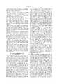
- FIG. 1is an elevational view of a hollow intramedullary tube and an associated extraction cap in accordance with an embodiment of the present invention
- FIG. 2is an elevational view of a plunger rod in accordance with an embodiment of the present invention
- FIG. 3is an elevational view of a modular plunger rod and associated modular centering devices, in accordance with another embodiment of the present invention.
- FIG. 4is an elevational view of a hollow bone graft packer in accordance with the present invention.
- FIG. 5is an elevational view of a plunger rod assembled within a hollow intramedullary tube (with extraction cap), illustrating in particular the packing of the tube/plunger assembly with bone graft through the use of a hollow bone graft packer;
- FIGS. 6A-6Fare elevational views, in partial cross-section of an implant technique in accordance with the present invention, illustrating in particular the delivery of bone graft to the proximal femoral medullary canal and the formation of the implant-receiving cavity within the graft-lined medullary canal;
- FIG. 7Ais a top plan view of a tube extractor (a modified cement injector) in accordance with the present invention.
- FIG. 7Bis an elevation view in partial cross-section of the bone graft delivery technique in accordance with the present invention, illustrating in particular the use of a tube extractor (associated with the extraction cap) to remove the hollow intramedullary tube from the medullary canal while leaving the plunger rod with the packed bone graft in place;
- a tube extractorassociated with the extraction cap
- FIG. 8is an elevational view of a plunger rod assembled within a hollow intramedullary tube, illustrating in particular adjunct centering means in the form of diametrically opposed centralizing screws;
- FIG. 9is an elevational view of a plunger rod assembled within a hollow intramedullary tube, illustrating in particular adjunct centering means in the form of a slideable centralizing washer held on the rod by an interference fit;
- FIG. 10is an elevational view, in partial cross-section, showing the selective delivery of bone graft to a specific area of the medullary canal through the use of a specifically structured plunger rod.
- FIGS. 1-4illustrate some of the instruments which may be used to facilitate the delivery of bone graft in accordance with the present invention.
- the instruments illustratedare for the delivery of bone graft to the femoral medullary canal, but the concepts underlying the present surgical technique may be applied to the delivery of bone graft to the medullary canal of any bone, adjacent to or remote from any joint.
- FIG. Ishows a hollow intramedullary tube 10 and an extraction cap 12 in accordance with the present invention.
- the tubeis preferably hollow from one end to the other, but may be partially hollow depending upon the application and structure of the instruments used with it. (The word “hollow” will thus be used in this sense.)
- the tube 10is preferably made of metal and preferably includes a thin-wall 10A (see FIG. 5) in at least the portion which will be inserted into a medullary canal.
- the tube 10includes a tube flange 14 and male threads adapted to receive the female threads of the extraction cap 12 (see FIG. 5).
- the extraction cap 12includes a groove 16 and retaining flange 18 for cooperation with the slotted retaining sleeve of a tube extractor (to be discussed later in connection with FIGS. 7A and 7B).
- the extraction cap 12can be made of any suitable material, such as plastic or metal.
- the hollow tube 10 and extraction cup 12may also be made of a disposable material, such as a disposable plastic, so that these instruments can be disposed of after they are used once. If made of a disposable material, the extractor cap 12 can be made integrally with the hollow tube 10. Moreover, the hollow tube 10 can be made to be stored with bone graft in it for a period of time, whether the tube 10 is made of plastic, metal or any other material. In this regard, depending upon the surgical application, it may be desirable to only partially fill the tube for storage or at least not pack it tightly, so that a plunger can be inserted at the time of a surgery.
- the tubemay also be made of a biocompatible material which can stay in the canal without impairing the final implantation. Alternatively, it may thus be a material that is resorbable, such as a resorbable polymer, in the canal after implantation, so as not to interfere with the growth of the bone or stability of the implant.
- the hollow tube 10can be of any suitable shape for insertion into the medullary canal of a bone (or any other area of the body) depending upon the application, but is preferably cylindrical in shape.
- “tube”shall be construed broadly to encompass structures of any suitable shape for retaining graft material prior to delivery to a medullary canal or any other area of the body.
- the tube 10is preferably made in several different diameters, for example 16 mm, 18 mm, 20 mm and 22 mm. The selection of the appropriate tube 10 will depend upon preoperative and intraoperative indications.
- the extraction cap 12is preferably a "universal" extraction cap in the sense that only one extraction cap will be needed for an entire set of differently sized hollow intramedullary tubes.
- an instrument kit for a particular jointmight include several differently-sized hollow intramedullary tubes to accommodate surgical needs.
- reamersmay be used to clean material (e.g., residual cement from previous implant, marrow, cancellous or cortical bone) out of the medullary canal prior to the insertion of the tube 10.
- materiale.g., residual cement from previous implant, marrow, cancellous or cortical bone
- An instrument kitmight thus include a set of reamers corresponding in size to the hollow intramedullary tubes in that instrument kit. Once a medullary canal has been prepared with the appropriately sized reamer, the corresponding tube will properly fit in the canal.
- FIG. 2shows a plunger of an elongate construction having a centralizing cap or flange 22 at one end (the proximal end) and a centralizing collar 24.
- the centralizing cap 22 and the centralizing collar 24are present to position--in this case, center--the plunger 20 within the tube 10.
- At least the centralizing collar 24also serves a graft retaining function during the delivery of the bone graft to the medullary canal. This ensures that the bone graft is not withdrawn from the medullary canal as the tube 10 is being withdrawn from the canal. This may occur by maintaining the collar 24 in one position while withdrawing the tube 10, or by pushing it toward the bone graft exit of the tube to push bone graft out of the tube.
- the centralizing collar 24may also facilitate the packing of the bone graft within the hollow tube 10 and within the medullary canal.
- bone graftcan be packed against the centralizing collar 24.
- additional bone graftmay be placed into the proximal femoral medullary canal by the surgeon's fingers, and the plunger 20 can be used to facilitate the packing of the additional bone graft.
- the collar 24further packs the additional bone graft in the proximal area.
- the centralizing cap 22 and the centralizing collar 24include grooves 22a and 24a, respectively, for the release of air during the surgical procedure. This will facilitate the use of the plunger 20 while packing the tube/plunger assembly outside of the bone and while impacting the plunger 20 to further pack the bone graft material within the medullary canal.
- the plunger 20includes a rod portion 21 below the centralizing collar 24, which is to be inserted into the medullary canal.
- Rod portion 21can be of any suitable size (length or thickness) and shape.
- the rod portion 21is cylindrical in shape for more than half of the rod portion 21, the lower approximately one third being slightly tapered, as shown in FIG. 2.
- the rod portion 21 of the plunger 20could emulate at least the distal portion of the implant stem which will finally be implanted in the canal, or it could emulate the entire stem of an implant. The degree of similarity between the rod portion 21 and the implant might depend on the joint being replaced, surgeon preference and other factors.
- the centralizing cap 22 and collar 24"bear" against the interior surface of the hollow tube in that these structures were undersized with regard to the interior diameter of the hollow tube 10. Any tolerance between the outer diameter of a positioning device and the inner diameter of the hollow tube 10 that facilitates the desired positioning function (and graft retaining function, if desirable) is acceptable. However, free sliding movement of such a positioning or graft retaining device within the hollow tube is preferable.
- the aboverelates to the preferred embodiment of the present invention in which the positioning and/or graft retaining device is inside the hollow tube 10.
- an instrument kit which includes several differently sized tubes 10must also include a number of plungers 20 which correspond in size to the tubes 10.
- FIG. 3illustrates a modular plunger, generally designated as 120 and having a rod portion 121, which is separate from an upper portion 121a.
- the rod portion 121can be integral with the upper portion 121a to form yet a different modular plunger.
- the rod portion 121 and upper portion 121acan be of different sizes, and an instrument kit may include several different sizes (widths and lengths) and shapes so that the rod portion 121 and upper portion 121a can be matched preoperatively or intraoperatively.
- the plunger 120is adapted to receive, via a threaded connection or otherwise, any one of a plurality of centralizing caps 122 and centralizing collars 124.
- the centralizing caps 122 and centralizing collars 124would be of different sizes to accommodate the differently sized tubes 10 within an instrument kit. Thus, one modular plunger 120 and several caps 122 and collars 124 would be required within a set of instruments. The appropriately sized centralizing caps 122 and centralizing collars 124 would be selected based on the selection of the tube 10. Of course, this type of modularity is not limited to centralizing caps and collars, but positioning devices of any type which might be used in connection with a plunger.
- FIG. 4shows a hollow bone graft packer 26 which is adapted to be telescopically inserted into the hollow intramedullary tube 10 while the plunger 20 is in place within the hollow intramedullary tube 10.
- the bone graft packer 26also includes grooves 26a for permitting air to escape during use, and further includes a knurled handle 26b at one end. As shown in FIG. 5, the bone graft packer 26 facilitates the packing of bone graft within the tube/plunger assembly.
- the bone graft packer 26may also include a device (not shown) arranged at the packing end to enlarge the end of the packer 26 and thus facilitate packing. Such a device might be removably attached to the end of the packer 26, perhaps by threads. The device would provide a greater packing area to pack the bone graft in the donut-shaped area around the plunger 20 and within the tube 10.
- the bone graft materialis packed within the tube 10 by the bone graft packer 26 such that the bone graft material 50 surrounds the rod portion 21 of plunger 20.
- the bone graft material 50is preferably packed as tightly as possible within the tube 10.
- the initial packing stepmay include inverting the tube/plunger assembly and pushing it into a container of bone graft to begin filling the tube with bone graft.
- FIG. 5illustrates the packing of the bone graft within the tube 10 while the plunger 20 is within the tube 10, the tube 10 could be partially or fully packed prior to insertion of the plunger 20. Once the plunger 20 is inserted into the tube 10, further compaction of the bone graft material 50 could be accomplished through the use of the bone graft packer 26.
- FIGS. 6A-6Fillustrate the delivery of the bone graft material 50 to the femoral medullary canal in accordance with an embodiment of the present invention.
- the tube/plunger assemblyprior to the steps shown in FIG. 6A, the tube/plunger assembly must be prepared (e.g., as described above with respect to FIG. 5), and the medullary canal of the distal femur must be prepared.
- a particular advantage of the preferred embodiment of the present inventionresides in the fact that the tube/plunger assembly can be packed and prepared for use prior to even exposing the patient's bone.
- the preparation of the distal femoral medullary canalmay include the revision or removal of a previously implanted hip implant, distal plug (if any) and any associated cements or other materials.
- An appropriately sized reamer, selected preoperatively and/or intraoperatively,may be used (if necessary) to clean the medullary canal to a size corresponding to the selected hollow intramedullary tube 10.
- the material cleaned outmay include cement, marrow and/or bone, depending upon surgeon preference, the application, etc.
- a distal plug 40may then be inserted into the medullary canal at a location which is selected preoperatively and/or intraoperatively.
- the next preferable step in the bone graft delivery technique in accordance with the present inventionis to pack an appropriate amount, e.g., 1-2 inches, of bone graft material 50 against the distal plug 40 (which can be of any suitable material or structure). This can be accomplished with any suitable instrument which fits into the medullary canal. The medullary canal is now prepared for receiving the tube/plunger assembly.
- the tube/plunger assemblyis inserted into the prepared femoral medullary canal against the distal plug 40 and/or any bone graft material which was previously packed against the distal plug 40.
- the plunger 20 illustrated in FIG. 6Ahas a rod portion 21 which is conical in shape as opposed to cylindrical with a distal taper (as in FIGS. 2 & 3).
- the plunger 20 in FIG. 6Aincludes a cap or thin flange 22 at its proximal end to facilitate the positioning, in this case centering, of the plunger 20 within the tube 10.
- FIG. 6Billustrates the delivery of the bone graft material 50 to the medullary canal by reason of the withdrawal of the tube 10 from the medullary canal, simultaneously with the application of pressure, from the proximal towards the distal end, of the plunger 20.
- the plunger 20may be held in one place (by such pressure) while the tube 10 is being withdrawn from the medullary canal, or further pressure can be applied to push the plunger 20 into the medullary canal at the same time the tube 10 is being withdrawn.
- Pressurecan be applied against the plunger 20 by the rod 39 of the extractor 36 (shown in FIG. 7B and described below), or with a rod driver (not shown), which may be held against the plunger 20 by the surgeon while withdrawing the tube 10. In some cases, there may be some incidental proximal movement of the plunger, but this is not preferable (even though the application of further pressure to the plunger will move the plunger into the desired position).
- the centralizing collar 24prevents at least any appreciable amount of bone graft 50 from moving out of the canal with the tube 10, and forces the bone graft 50 distally so that it is transferred into the canal.
- the space occupied by its thin walls 10Ais filled with the bone graft material 50. Preferably, it is then packed more tightly by the plunger 20.
- the plunger 20is preferably forced further into the medullary canal to further compact the bone graft material 50. This can be accomplished in any suitable manner, including the impaction of the top of the plunger 20.
- FIG. 6Cshows the further compaction of the bone graft material.
- the medullary canalis now prepared for trial packing and reduction.
- the packingis accomplished through the sequential use of a set of trial implants, ranging from small to larger.
- trial implantsoften have a shape which is the same or similar to the final implant.
- FIG. 6Eshows a trial hip implant 30, which represents any trial of a set of differently sized trial hip implants. While the bone graft 50 has been well compacted through the use of the plunger 20, trial implant 30 and subsequent trial implants are used within the plunger cavity 28 to shape the bone graft 50 and thus form a cavity which matches the final implant, as shown in FIG. 6E.
- the sequential use of successively larger trial implantsfacilitates the efficient shaping of the bone graft 50.
- the last trial implant usedmay match the size, as well as the shape, of the final implant, or if the final implant is to be cemented, the last trial implant used may be of a size larger than the size of the final implant. This will leave sufficient room for a cement mantle 32 within the cavity formed in the bone graft 50.
- FIG. 6Fshows the implantation of the final implant 35. As is shown in FIG. 6F, a cement mantle space 32 is provided between the bone graft 50 and the implant 35.
- the present inventionrelates not only to the delivery of bone graft material to the medullary canal of a bone, but also relates to the delivery of bone graft material to any portion of a bone which requires bone graft material.
- the techniquecontemplates delivery to a window cut in a bone, where access to such window for bone grafting is difficult to obtain because of muscle tissue, etc.
- the window in the bonemay not be fully exposed, such that the hollow tube may be helpful in selectively and controllably placing bone graft material in or adjacent to such window.
- the present inventionalso contemplates the delivery of bone graft material with or without the use of a plunger to form a cavity in delivered bone graft material.
- the bone graft materialcan simply be delivered to an area via the hollow tube and without the plunger.
- FIG. 7Ashows a tube extractor 36, which is quite similar to a caulk gun used to dispel adhesive from an adhesive tube. Specifically, for purposes of this invention, modifications were made to a cement injector sold by Stryker corporation of Kalamazoo, Mich. under catalog #206-600. The modified cement injector or tube extractor 36 can be used to facilitate the withdrawal of the tube 10 during the delivery of the bone graft 50 into the medullary canal.
- the tube extractor 36includes a slotted retaining sleeve 38 which has a slot 38A for receiving the retaining flange 18 of the extraction cap 12 (shown in FIG. 7B), thereby connecting the extractor 36 to the extraction cap 12 and thus the tube 10.
- the slot 38A and the slotted retaining sleeve 38have been in other instances used to hold the flange of a container of cement or other material.
- the extractor 36includes a rod 39 and a rod collar 39a which will bear against the centralizing cap 22 or other structure at the end of the plunger 20. This is shown in the cutaway portion in FIG. 7B.
- the rod 39includes ratchet teeth 39b which facilitate the advancement of the rod 39 when the extractor handle 37 is actuated.
- any other suitable means for advancing the rod 39can be used.
- FIG. 7Bshows the extractor 36 connected to the extraction cap 12 via the slotted retaining sleeve 38 of the extractor 36 and the groove 16 and retaining flange 18 of the extraction cap 12.
- the extraction cap 12is connected to the tube 10 against the tube flange 14.
- the plunger 20is assembled within the tube 10 and is surrounded by the bone graft 50.
- the rod collar 39ais shown in the cut-away portion bearing against the centralizing cap 22.
- the rod 39 of extractor 36will be forced downwardly against the plunger 20. Because the plunger 20 is bearing against either the distal plug 40 or compacted bone graft 50 which is against the distal plug 40, the tube 10 will move distally out of the medullary canal, leaving the plunger 20 in place (or forcing it further downwardly). While the tube 10 can be withdrawn in any suitable manner, the use of the extractor 36 may be quite helpful in controllably removing the tube 10.
- FIG. 8illustrates the use of two centralizing screws 52a and 52b, which threadedly engage diametrically opposed holes in the tube 10 and engage the rod portion 21. Together these centralizing screws help ensure that the rod portion 21 remains in the centralized position.
- centralizing screws 52a and 52bmay be changed to accommodate any position (other than central) of the rod portion 21 within the tube 10.
- the centralizing screws 52a and 52bare disclosed as adjunct positioning means, they can be used (as shown or in additional pairs) as primary positioning means in lieu of cap 22 and collar 24, or just in lieu of collar 24 (so that they would work with cap 22).
- FIG. 9illustrates yet another technique for ensuring that the rod portion 21 remain in the centralized position (or any other desirable position).
- a centralizing washer 54(or multiple such washers) may be used.
- This washer 54preferably made out of a plastic material, is inserted over the rod portion 21, and remains in place by an interference fit.
- radial relief cutsare made from the central hole, so that the washer can be slid over a tapering rod.
- the washer 54can be further forced onto the cylindrical portion of the rod portion 21 during the packing of the tube/plunger assembly.
- the washer 54will finally rest against the centralizing collar 24, but in the meantime will have helped ensure that the position of the rod portion 21 remains as it was originally set.
- the washer 54is preferably biocompatible and detectable by X-ray. It might be such that the washer 54 can be left in place with no harm to the subsequent implantation, or the washer 54 can be extracted prior to finally preparing the canal.
- the washer 54 or multiple washersmay be useable as the primary positioning means, alone or with one or both of cap 22 or collar 24.
- FIG. 10illustrates a particular specialized application using the present invention.
- the distal femoral boneincludes a void 42 on the lateral side of the medullary canal.
- the objectiveis to selectively place bone graft 50 only in void 42.
- the selective delivery of bone graftcan be accomplished through the use of a tube 10 and a plunger 20, wherein the plunger 20 has a particular shape and/or orientation with regard to the tube 10 to facilitate selective delivery of the bone graft 50 to the void 42.
- FIG. 10One way of accomplishing this is shown in FIG. 10. In FIG.
- the bone graft 50is only provided on the lateral side of the plunger 20. It is also noted that the plunger 20 includes flattened areas at least at the top of proximal portion to facilitate the positioning of the plunger 20 within the tube 10. Upon withdrawal of the tube 10, and the further compaction of the bone graft 50, the void 42 is filled or at least partially filled with the bone graft 50. A further procedure, such as implantation of a prosthetic device, can now be undertaken.
Landscapes
- Health & Medical Sciences (AREA)
- Transplantation (AREA)
- Orthopedic Medicine & Surgery (AREA)
- Heart & Thoracic Surgery (AREA)
- Life Sciences & Earth Sciences (AREA)
- Oral & Maxillofacial Surgery (AREA)
- Engineering & Computer Science (AREA)
- Biomedical Technology (AREA)
- Physical Education & Sports Medicine (AREA)
- Vascular Medicine (AREA)
- Cardiology (AREA)
- Animal Behavior & Ethology (AREA)
- General Health & Medical Sciences (AREA)
- Public Health (AREA)
- Veterinary Medicine (AREA)
- Prostheses (AREA)
- Surgical Instruments (AREA)
Abstract
Description
This application is a continuation of Ser. No. 08/336,841, filed Nov. 9, 1994, now U.S. Pat. No. 5,697,932.
The present invention relates generally to a method of surgically implanting a new prosthesis at a joint, and more specifically to instruments and techniques for efficiently using bone graft to facilitate the implantation of a prosthesis.
It is known to use bone graft to prepare a seat for a prosthesis, either with or without a cement mantle. A bone grafting procedure is often used where there is an appreciable loss of strong bone stock, as is often the case in revision surgery (in which a previously implanted prosthesis is replaced with a new prosthesis). The seat prepared with bone graft may be made up entirely of bone graft to substantially surround a prosthesis, or the seat may be made up of bone graft and the natural bone at the implantation site (for instance, where bone graft is used to fill a relatively small void in the natural bone where the bone is otherwise intact). Bone graft typically includes crushed bone (cancellous and cortical), or a combination of these (and/or other natural materials) and synthetic biocompatible materials. Bone graft of this type is intended to stimulate growth of healthy bone. As used herein, "bone graft" shall mean materials made up entirely of natural materials, entirely of synthetic biocompatible materials, or any combination of these materials.
U.S. Pat. No. 5,015,256 to Bruce discloses a surgical technique by which the medullary canal is reamed and filled with bone graft, the bone graft being compacted by driving the stem of the prosthesis into the medullary canal. Also, U.S. Pat. No. 4,800,875 to Ray discloses a method of inserting bone graft into a bone and tamping the bone graft. European Patent Publication No. 0 179 626 A2 discloses the use of bone graft to enhance implant/bone contact, whereby the stem of a hip implant is intended to subside within an implant sleeve. Also, an article entitled "Histology Of Cancellous Impaction Grafting In The Femur," by Ling et al., Journal of Bone and Joint Surgery [Br], Vol. 75-B, No. 5, September 1993, reports a 1988 revision of a hip implant in which allograft chips were impacted within the medullary canal with an oversized stem, followed by use of cement and implantation of a polished-surface stem. In addition, Complications Of Total Hip Arthoplasty, by Richard H. Rothman and William J. Hozack, W. B. Saunders Co., 1988, teaches a technique of bone grafting in the femoral canal in a revision surgery, using uncemented components.
Of course, it is desirable to properly prepare the medullary canal adjacent a joint for receiving bone graft so that a prosthesis can be properly positioned during implantation. Thus, the preparation of the medullary canal and the positioning of the prosthesis or trial prosthesis in the prepared medullary canal are often critical steps in properly implanting a prosthesis. To this end, rasps having a configuration similar to the prosthesis are well-known, as shown, for example, in U.S. Pat. No. 3,874,003 to Moser (FIG. 8), U.S. Pat. No. 4,306,550 to Forte and U.S. Pat. No. 4,552,136 to Kenna. These devices facilitate the proper shaping of the femoral medullary canal in a configuration which is similar to their respective hip prostheses or trial hip prostheses.
Centering devices (rods and guidewires) are also known for controlling the machining or other preparation of the medullary canal, as well as for centering a trial prosthesis during trial reduction or centering a prosthesis during implantation. U.S. Pat. No. 4,919,673 to Willert, U.S. Pat. No. 4,994,085 to Sawai and U.S. Pat. No. 5,078,746 to Garner each disclose the use of centering rods in the distal femoral canal to center hip joint prostheses and/or trial hip joint prostheses during trial reduction and final implantation. The hip joint prostheses and trial hip joint prostheses each have longitudinal passageways which receive the centering rods or guidewires already in the canal. Centering rods or guidewires are also used in connection with machining and shaping instruments so that the preparation of the canal is controlled about the centering rod or guidewire and so that the preparation is consistent from instrument to instrument. U.S. Pat. No. 4,341,206 to Perrett, U.S. Pat. No. 4,751,922 to DiPietropolo, U.S. Pat. No. 5,192,283 to Ling, U.S. Pat. No. 5,122,134 to Borzone and U.S. Pat. No. 5,190,548 to Davis disclose cannulated reamers and drills which are used with centering rods or guidewires for centering or positioning the shaping tools during preparation of a medullary canal or bone.
U.S. Pat. No. 5,192,283 to Ling also discloses the use of a trial hip prosthesis having a longitudinal passageway for receiving the very guidewire which facilitated the reaming and rasping of the canal. Bone graft is inserted into the canal around the guidewire, and the cannulated trial prosthesis is used to simultaneously compact and form or shape a prosthesis-receiving cavity larger than and similar in shape to the new prosthesis. Bone graft is continuously placed into the canal during the use of the cannulated trial prosthesis in order to build up the bone graft in the canal. A series of successively larger cannulated trial prostheses could be used to compact the bone graft.
The technique described in Ling is a somewhat time-consuming surgical procedure. Factors which add to the time-consuming nature of this technique include the steps which must be repeated to complete the insertion of bone graft into the canal and the requirement that all steps take place in the medullary canal. In addition, the technique described in Ling relies on a guidewire which could shift during preparation of the canal.
The present invention provides an easily implemented and efficient technique for the delivery of bone graft to a medullary canal or elsewhere in the body. One embodiment relates specifically to bone grafting within the medullary canal adjacent a joint to prepare the canal for receiving a prosthesis.
The present invention is directed to the delivery of bone graft materials to any area of the body and in particular to the medullary canal of any bone. The invention can be used in the repair of a bone or in connection with the implantation of prosthetic devices at any bone in the body, including without limitation the hip, knee and spinal joints. Further, the present invention can be used in primary surgery, in which a prosthesis is being used to reconstruct a joint for the first time, as well as in revision surgery, in which a previously-implanted prosthesis is being replaced with another prosthesis. Press fit, cement or other fixation techniques can be employed in conjunction with the present invention. The technique in accordance with the present invention is suitable for the delivery of bone graft into the medullary canal to fully or partially line the medullary canal.
It is an object of the present invention to provide a bone graft delivery system for delivering bone graft, in a partially formed, fully formed or unformed condition to a graft receiving area in a body. The graft receiving area can be any area, but is often the medullary canal of a bone. In the preferred embodiment, the bone graft is delivered in a partially formed manner, and in accordance with another aspect of the present invention, requires further formation after initial delivery of the bone graft.
It is another object of the present invention to provide a method and apparatus by which a hollow tube and a plunger associated with the hollow tube are provided to facilitate delivery of the bone graft to a bone graft receiving area. In the preferred embodiment, positioning structure is provided on the plunger to maintain the plunger in a desirable position with respect to the hollow tube. Adjunct positioning means may also be provided to ensure that the plunger remains in the desirable position during the packing of bone graft into the hollow tube.
It is another object of the present invention to provide a method and apparatus by which a plunger and hollow tube assembly can be packed with bone graft, and then together inserted into the medullary canal or adjacent to another bone graft receiving area. Subsequently, the hollow tube can be withdrawn to leave the plunger in place in order to form in the bone graft a cavity in the shape of the plunger. In the preferred embodiment, the plunger can then be removed, and a series of sequentially larger trials can be used to shape the bone graft within the medullary canal.
It is another object of the present invention to provide a bone graft delivery system, by which bone graft can be selectively and controllably delivered to a specific area. For instance, bone graft may be delivered to one portion of the wall in the medullary canal, as opposed all of the walls in the medullary canal.
It is another object of the present invention to provide a hollow tube and plunger assembly, in which the hollow tube is disposable.
It is another object of the present invention to provide a bone graft delivery system, by which a hollow tube and possibly a hollow tube/plunger assembly can be prepared prior to even opening a patient, thus minimizing the overall impact of the grafting aspect of a surgical implantation or other procedure.
The present invention can be carried out by a method in which access is provided to a graft receiving area in a body, bone graft is placed into a hollow tube having a first end and a second end, the hollow tube, together with the bone graft, is arranged so that the first end of the hollow tube is at least adjacent to the graft receiving area, and the hollow tube is moved away from the graft receiving area, in a direction from the first end to the second end of the hollow tube, such that the bone graft exits the first end of the hollow tube and remains at the graft receiving area. A graft retaining structure may also be provided to block an end of the hollow tube, so as to facilitate the exit of the bone graft from the hollow tube. The graft retaining structure may also be used in such a way that it is maintained in one position while the tube is moved away from the graft receiving area. Alternatively, the graft retaining structure can be used by forcing it toward the graft receiving area, while the hollow tube is being moved away from the graft receiving area.
The present invention may also be carried out by exposing the medullary canal of a bone, placing bone graft into a hollow tube having a first end and a second end, inserting the first end of the hollow tube into the medullary canal, and withdrawing the hollow tube from the medullary canal, such that bone graft exits the first end of the hollow tube into the medullary canal. Again, the bone graft can be forced from the hollow tube by blocking an end of the hollow tube. The above technique may also include arranging a plunger having an elongate rod portion at least partially in the hollow tube and removing the plunger from the medullary canal to leave a cavity formed at least partially in the bone graft. The hollow tube can be inserted into the medullary canal together with the plunger and bone graft, and upon withdrawal of the hollow tube from the medullary canal, the plunger remains at least partially in the canal. Pressure can be applied to the plunger during withdrawal of the hollow tube to at least maintain the plunger at least partially in the medullary canal. Further pressure may also be applied to the plunger to force the plunger further into the medullary canal, either while withdrawing the hollow tube from the medullary canal or subsequent to the withdrawal of the hollow tube, whereby the bone graft deposited in the medullary canal would be further packed by the plunger.
The bone graft deposited in the medullary canal by the tube/plunger assembly can be shaped, if not already shaped, with a prosthesis or a trial prosthesis having a configuration similar to the prosthesis to be implanted. The bone graft material in the medullary canal can be compacted with successively larger trial prostheses to progressively shape the bone graft. If the prosthesis to be implanted is to be cemented in place in the canal, the final trial prosthesis used to shape the bone graft can be of a size larger than the prosthesis to be implanted, so as to leave a cement mantle.
The plunger used in connection with the hollow tube can be modular in nature, such that different portions of the plunger can be matched according to preoperative or intraoperative indications. Also, any positioning devices or graft retaining structures used in connection with the plunger can also be modular and selectable from a group of different devices to fit the particular application and hollow tube.
The present invention may also be carried out by providing a hollow tube having a first end and a second end, and being constructed so that it can receive bone graft, and so that the first end can be arranged at least adjacent to a bone graft receiving area, and so that bone graft can be delivered from the first end of the hollow tube to the bone graft receiving area upon movement of the hollow tube in a direction from the first end to the second end. A graft retaining structure can also be provided for use in connection with the hollow tube, as can a graft packer. In addition, a plunger can be provided with the hollow tube.
Another aspect of the present invention can be carried out by providing an extractor to facilitate the controlled movement of a tube which surrounds a rod, while leaving the rod substantially in position, the extractor including a housing, a connector for connecting the housing to the tube, a stem movable within the housing for applying pressure to a rod in its arranged position, and actuating means for applying pressure to such a rod. The stem may have a rod-engaging portion sized to engage a rod in a tube and to permit the tube to be withdrawn from around the rod so that the tube is disposed around the stem. The extractor is constructed and arranged so that upon actuation thereof, the stem applies pressure against the rod, and the housing, with a connected tube, is moved away from the arranged position, while leaving the rod in the arranged position.
The foregoing and other objects of the present invention will become apparent, as will a better understanding of the concepts underlying the present invention, by reference to the description which follows and refers to the accompanying drawings in which:
FIG. 1 is an elevational view of a hollow intramedullary tube and an associated extraction cap in accordance with an embodiment of the present invention;
FIG. 2 is an elevational view of a plunger rod in accordance with an embodiment of the present invention;
FIG. 3 is an elevational view of a modular plunger rod and associated modular centering devices, in accordance with another embodiment of the present invention;
FIG. 4 is an elevational view of a hollow bone graft packer in accordance with the present invention;
FIG. 5 is an elevational view of a plunger rod assembled within a hollow intramedullary tube (with extraction cap), illustrating in particular the packing of the tube/plunger assembly with bone graft through the use of a hollow bone graft packer;
FIGS. 6A-6F are elevational views, in partial cross-section of an implant technique in accordance with the present invention, illustrating in particular the delivery of bone graft to the proximal femoral medullary canal and the formation of the implant-receiving cavity within the graft-lined medullary canal;
FIG. 7A is a top plan view of a tube extractor (a modified cement injector) in accordance with the present invention;
FIG. 7B is an elevation view in partial cross-section of the bone graft delivery technique in accordance with the present invention, illustrating in particular the use of a tube extractor (associated with the extraction cap) to remove the hollow intramedullary tube from the medullary canal while leaving the plunger rod with the packed bone graft in place;
FIG. 8 is an elevational view of a plunger rod assembled within a hollow intramedullary tube, illustrating in particular adjunct centering means in the form of diametrically opposed centralizing screws;
FIG. 9 is an elevational view of a plunger rod assembled within a hollow intramedullary tube, illustrating in particular adjunct centering means in the form of a slideable centralizing washer held on the rod by an interference fit; and
FIG. 10 is an elevational view, in partial cross-section, showing the selective delivery of bone graft to a specific area of the medullary canal through the use of a specifically structured plunger rod.
FIGS. 1-4 illustrate some of the instruments which may be used to facilitate the delivery of bone graft in accordance with the present invention. The instruments illustrated are for the delivery of bone graft to the femoral medullary canal, but the concepts underlying the present surgical technique may be applied to the delivery of bone graft to the medullary canal of any bone, adjacent to or remote from any joint.
FIG. I shows ahollow intramedullary tube 10 and anextraction cap 12 in accordance with the present invention. The tube is preferably hollow from one end to the other, but may be partially hollow depending upon the application and structure of the instruments used with it. (The word "hollow" will thus be used in this sense.) Thetube 10 is preferably made of metal and preferably includes a thin-wall 10A (see FIG. 5) in at least the portion which will be inserted into a medullary canal. Thetube 10 includes a tube flange 14 and male threads adapted to receive the female threads of the extraction cap 12 (see FIG. 5). Theextraction cap 12 includes a groove 16 and retaining flange 18 for cooperation with the slotted retaining sleeve of a tube extractor (to be discussed later in connection with FIGS. 7A and 7B). Theextraction cap 12 can be made of any suitable material, such as plastic or metal.
Thehollow tube 10 andextraction cup 12 may also be made of a disposable material, such as a disposable plastic, so that these instruments can be disposed of after they are used once. If made of a disposable material, theextractor cap 12 can be made integrally with thehollow tube 10. Moreover, thehollow tube 10 can be made to be stored with bone graft in it for a period of time, whether thetube 10 is made of plastic, metal or any other material. In this regard, depending upon the surgical application, it may be desirable to only partially fill the tube for storage or at least not pack it tightly, so that a plunger can be inserted at the time of a surgery. The tube may also be made of a biocompatible material which can stay in the canal without impairing the final implantation. Alternatively, it may thus be a material that is resorbable, such as a resorbable polymer, in the canal after implantation, so as not to interfere with the growth of the bone or stability of the implant.
Thehollow tube 10 can be of any suitable shape for insertion into the medullary canal of a bone (or any other area of the body) depending upon the application, but is preferably cylindrical in shape. In this regard, as used herein, "tube" shall be construed broadly to encompass structures of any suitable shape for retaining graft material prior to delivery to a medullary canal or any other area of the body. Thetube 10 is preferably made in several different diameters, for example 16 mm, 18 mm, 20 mm and 22 mm. The selection of theappropriate tube 10 will depend upon preoperative and intraoperative indications. In this regard, theextraction cap 12 is preferably a "universal" extraction cap in the sense that only one extraction cap will be needed for an entire set of differently sized hollow intramedullary tubes. Thus, an instrument kit for a particular joint might include several differently-sized hollow intramedullary tubes to accommodate surgical needs.
As will be discussed in more detail below, reamers may be used to clean material (e.g., residual cement from previous implant, marrow, cancellous or cortical bone) out of the medullary canal prior to the insertion of thetube 10. An instrument kit might thus include a set of reamers corresponding in size to the hollow intramedullary tubes in that instrument kit. Once a medullary canal has been prepared with the appropriately sized reamer, the corresponding tube will properly fit in the canal.
FIG. 2 shows a plunger of an elongate construction having a centralizing cap orflange 22 at one end (the proximal end) and a centralizingcollar 24. The centralizingcap 22 and the centralizingcollar 24 are present to position--in this case, center--theplunger 20 within thetube 10. At least the centralizingcollar 24 also serves a graft retaining function during the delivery of the bone graft to the medullary canal. This ensures that the bone graft is not withdrawn from the medullary canal as thetube 10 is being withdrawn from the canal. This may occur by maintaining thecollar 24 in one position while withdrawing thetube 10, or by pushing it toward the bone graft exit of the tube to push bone graft out of the tube. The centralizingcollar 24 may also facilitate the packing of the bone graft within thehollow tube 10 and within the medullary canal. In thetube 10, bone graft can be packed against the centralizingcollar 24. In the medullary canal, after thetube 10 is withdrawn, additional bone graft may be placed into the proximal femoral medullary canal by the surgeon's fingers, and theplunger 20 can be used to facilitate the packing of the additional bone graft. By alternately lifting theplunger 20 out of the canal and inserting it back into the canal to impact the bone graft, thecollar 24 further packs the additional bone graft in the proximal area.
Of course, various structures or devices could be used to center or otherwise position theplunger 20 or to ensure that the bone graft is transferred to the canal upon the withdrawal of thehollow tube 10. See, for example, the plunger shown in FIGS. 6A-6C and 10, which show positioning structures only at the proximal end of the plungers. However, the use of a centralizingcap 22 and a centralizingcollar 24, separately situated, may be effective in reducing any toggle of theplunger 20 within thetube 10 and thus to maintain theplunger 20 within the desired position.
The centralizingcap 22 and the centralizingcollar 24 include grooves 22a and 24a, respectively, for the release of air during the surgical procedure. This will facilitate the use of theplunger 20 while packing the tube/plunger assembly outside of the bone and while impacting theplunger 20 to further pack the bone graft material within the medullary canal.
Theplunger 20 includes a rod portion 21 below the centralizingcollar 24, which is to be inserted into the medullary canal. Rod portion 21 can be of any suitable size (length or thickness) and shape. In the preferred embodiment, the rod portion 21 is cylindrical in shape for more than half of the rod portion 21, the lower approximately one third being slightly tapered, as shown in FIG. 2. In fact, the rod portion 21 of theplunger 20 could emulate at least the distal portion of the implant stem which will finally be implanted in the canal, or it could emulate the entire stem of an implant. The degree of similarity between the rod portion 21 and the implant might depend on the joint being replaced, surgeon preference and other factors.
In the preferred embodiment, the centralizingcap 22 andcollar 24 "bear" against the interior surface of the hollow tube in that these structures were undersized with regard to the interior diameter of thehollow tube 10. Any tolerance between the outer diameter of a positioning device and the inner diameter of thehollow tube 10 that facilitates the desired positioning function (and graft retaining function, if desirable) is acceptable. However, free sliding movement of such a positioning or graft retaining device within the hollow tube is preferable. Of course, the above relates to the preferred embodiment of the present invention in which the positioning and/or graft retaining device is inside thehollow tube 10. Also, since the centralizingcap 22 andcollar 24 in the preferred embodiment are sized to fit within thehollow tube 10, an instrument kit which includes several differentlysized tubes 10 must also include a number ofplungers 20 which correspond in size to thetubes 10.
FIG. 3 illustrates a modular plunger, generally designated as 120 and having a rod portion 121, which is separate from an upper portion 121a. (Alternatively, the rod portion 121 can be integral with the upper portion 121a to form yet a different modular plunger.) The rod portion 121 and upper portion 121a can be of different sizes, and an instrument kit may include several different sizes (widths and lengths) and shapes so that the rod portion 121 and upper portion 121a can be matched preoperatively or intraoperatively. The plunger 120 is adapted to receive, via a threaded connection or otherwise, any one of a plurality of centralizing caps 122 and centralizing collars 124. The centralizing caps 122 and centralizing collars 124 would be of different sizes to accommodate the differentlysized tubes 10 within an instrument kit. Thus, one modular plunger 120 and several caps 122 and collars 124 would be required within a set of instruments. The appropriately sized centralizing caps 122 and centralizing collars 124 would be selected based on the selection of thetube 10. Of course, this type of modularity is not limited to centralizing caps and collars, but positioning devices of any type which might be used in connection with a plunger.
FIG. 4 shows a hollowbone graft packer 26 which is adapted to be telescopically inserted into thehollow intramedullary tube 10 while theplunger 20 is in place within thehollow intramedullary tube 10. Thebone graft packer 26 also includes grooves 26a for permitting air to escape during use, and further includes a knurled handle 26b at one end. As shown in FIG. 5, thebone graft packer 26 facilitates the packing of bone graft within the tube/plunger assembly. Thebone graft packer 26 may also include a device (not shown) arranged at the packing end to enlarge the end of thepacker 26 and thus facilitate packing. Such a device might be removably attached to the end of thepacker 26, perhaps by threads. The device would provide a greater packing area to pack the bone graft in the donut-shaped area around theplunger 20 and within thetube 10.
As shown in FIG. 5, the bone graft material, generally designated as 50, is packed within thetube 10 by thebone graft packer 26 such that thebone graft material 50 surrounds the rod portion 21 ofplunger 20. Here, thebone graft material 50 is preferably packed as tightly as possible within thetube 10. The initial packing step may include inverting the tube/plunger assembly and pushing it into a container of bone graft to begin filling the tube with bone graft.
While FIG. 5 illustrates the packing of the bone graft within thetube 10 while theplunger 20 is within thetube 10, thetube 10 could be partially or fully packed prior to insertion of theplunger 20. Once theplunger 20 is inserted into thetube 10, further compaction of thebone graft material 50 could be accomplished through the use of thebone graft packer 26.
FIGS. 6A-6F illustrate the delivery of thebone graft material 50 to the femoral medullary canal in accordance with an embodiment of the present invention. However, prior to the steps shown in FIG. 6A, the tube/plunger assembly must be prepared (e.g., as described above with respect to FIG. 5), and the medullary canal of the distal femur must be prepared. A particular advantage of the preferred embodiment of the present invention resides in the fact that the tube/plunger assembly can be packed and prepared for use prior to even exposing the patient's bone.
The preparation of the distal femoral medullary canal may include the revision or removal of a previously implanted hip implant, distal plug (if any) and any associated cements or other materials. An appropriately sized reamer, selected preoperatively and/or intraoperatively, may be used (if necessary) to clean the medullary canal to a size corresponding to the selected hollowintramedullary tube 10. The material cleaned out may include cement, marrow and/or bone, depending upon surgeon preference, the application, etc. Adistal plug 40 may then be inserted into the medullary canal at a location which is selected preoperatively and/or intraoperatively. The next preferable step in the bone graft delivery technique in accordance with the present invention is to pack an appropriate amount, e.g., 1-2 inches, ofbone graft material 50 against the distal plug 40 (which can be of any suitable material or structure). This can be accomplished with any suitable instrument which fits into the medullary canal. The medullary canal is now prepared for receiving the tube/plunger assembly.
As shown in FIG. 6A, the tube/plunger assembly is inserted into the prepared femoral medullary canal against thedistal plug 40 and/or any bone graft material which was previously packed against thedistal plug 40. It is noted that theplunger 20 illustrated in FIG. 6A has a rod portion 21 which is conical in shape as opposed to cylindrical with a distal taper (as in FIGS. 2 & 3). Also, theplunger 20 in FIG. 6A includes a cap orthin flange 22 at its proximal end to facilitate the positioning, in this case centering, of theplunger 20 within thetube 10.
FIG. 6B illustrates the delivery of thebone graft material 50 to the medullary canal by reason of the withdrawal of thetube 10 from the medullary canal, simultaneously with the application of pressure, from the proximal towards the distal end, of theplunger 20. Theplunger 20 may be held in one place (by such pressure) while thetube 10 is being withdrawn from the medullary canal, or further pressure can be applied to push theplunger 20 into the medullary canal at the same time thetube 10 is being withdrawn. Pressure can be applied against theplunger 20 by the rod 39 of the extractor 36 (shown in FIG. 7B and described below), or with a rod driver (not shown), which may be held against theplunger 20 by the surgeon while withdrawing thetube 10. In some cases, there may be some incidental proximal movement of the plunger, but this is not preferable (even though the application of further pressure to the plunger will move the plunger into the desired position).
During withdrawal of thetube 10, the centralizing collar 24 (shown in FIG. 2) prevents at least any appreciable amount ofbone graft 50 from moving out of the canal with thetube 10, and forces thebone graft 50 distally so that it is transferred into the canal. As thetube 10 is withdrawn from the medullary canal, the space occupied by its thin walls 10A is filled with thebone graft material 50. Preferably, it is then packed more tightly by theplunger 20.
Following the withdrawal of thetube 10, theplunger 20 is preferably forced further into the medullary canal to further compact thebone graft material 50. This can be accomplished in any suitable manner, including the impaction of the top of theplunger 20. FIG. 6C shows the further compaction of the bone graft material. Once the desired degree of bone graft compaction has been attained, theplunger 20 is removed from the medullary canal. The length of theplunger 20 between the centralizingcollar 24 andcap 22, and thecap 22 itself, facilitate the removal of theplunger 20. This leaves a plunger cavity 28 within the packed bone graft material, as shown in FIG. 6D.
The medullary canal is now prepared for trial packing and reduction. Preferably, the packing is accomplished through the sequential use of a set of trial implants, ranging from small to larger. As is well known in the field, trial implants often have a shape which is the same or similar to the final implant. FIG. 6E shows atrial hip implant 30, which represents any trial of a set of differently sized trial hip implants. While thebone graft 50 has been well compacted through the use of theplunger 20,trial implant 30 and subsequent trial implants are used within the plunger cavity 28 to shape thebone graft 50 and thus form a cavity which matches the final implant, as shown in FIG. 6E. The sequential use of successively larger trial implants facilitates the efficient shaping of thebone graft 50. The last trial implant used may match the size, as well as the shape, of the final implant, or if the final implant is to be cemented, the last trial implant used may be of a size larger than the size of the final implant. This will leave sufficient room for a cement mantle 32 within the cavity formed in thebone graft 50. During the use of thetrial implants 30 to shape the plunger cavity 28, it is preferable to finger-pack or otherwise packbone graft 50 in the proximal area of the femoral medullary canal so that the shape of the proximal portion of thetrial implant 30, and thus thefinal implant 35, is adequately formed in the canal.
FIG. 6F shows the implantation of thefinal implant 35. As is shown in FIG. 6F, a cement mantle space 32 is provided between thebone graft 50 and theimplant 35.
The present invention relates not only to the delivery of bone graft material to the medullary canal of a bone, but also relates to the delivery of bone graft material to any portion of a bone which requires bone graft material. Thus, for example, the technique contemplates delivery to a window cut in a bone, where access to such window for bone grafting is difficult to obtain because of muscle tissue, etc. In other words, the window in the bone may not be fully exposed, such that the hollow tube may be helpful in selectively and controllably placing bone graft material in or adjacent to such window. The present invention also contemplates the delivery of bone graft material with or without the use of a plunger to form a cavity in delivered bone graft material. Thus, the bone graft material can simply be delivered to an area via the hollow tube and without the plunger.
FIG. 7A shows a tube extractor 36, which is quite similar to a caulk gun used to dispel adhesive from an adhesive tube. Specifically, for purposes of this invention, modifications were made to a cement injector sold by Stryker corporation of Kalamazoo, Mich. under catalog #206-600. The modified cement injector or tube extractor 36 can be used to facilitate the withdrawal of thetube 10 during the delivery of thebone graft 50 into the medullary canal. The tube extractor 36 includes a slotted retaining sleeve 38 which has a slot 38A for receiving the retaining flange 18 of the extraction cap 12 (shown in FIG. 7B), thereby connecting the extractor 36 to theextraction cap 12 and thus thetube 10. The slot 38A and the slotted retaining sleeve 38 have been in other instances used to hold the flange of a container of cement or other material. The extractor 36 includes a rod 39 and a rod collar 39a which will bear against the centralizingcap 22 or other structure at the end of theplunger 20. This is shown in the cutaway portion in FIG. 7B. As with many caulk guns, the rod 39 includes ratchet teeth 39b which facilitate the advancement of the rod 39 when the extractor handle 37 is actuated. However, any other suitable means for advancing the rod 39 can be used.
FIG. 7B shows the extractor 36 connected to theextraction cap 12 via the slotted retaining sleeve 38 of the extractor 36 and the groove 16 and retaining flange 18 of theextraction cap 12. In FIG. 7B, theextraction cap 12 is connected to thetube 10 against the tube flange 14. Theplunger 20 is assembled within thetube 10 and is surrounded by thebone graft 50. The rod collar 39a is shown in the cut-away portion bearing against the centralizingcap 22.
In practice, upon the actuation of the extractor handle 37, the rod 39 of extractor 36 will be forced downwardly against theplunger 20. Because theplunger 20 is bearing against either thedistal plug 40 or compactedbone graft 50 which is against thedistal plug 40, thetube 10 will move distally out of the medullary canal, leaving theplunger 20 in place (or forcing it further downwardly). While thetube 10 can be withdrawn in any suitable manner, the use of the extractor 36 may be quite helpful in controllably removing thetube 10.
While centralizingcap 22 andcollar 24 serve the purpose, among others, of centralizing the rod portion 21 ofplunger 20 during initial assembly of thetube 10 andplunger 20, it is possible that the centralized position might be moved after that initial assembly. This may occur during the insertion and packing of thebone graft material 50 around the rod portion 21 within thetube 10. To ensure that the packing of thebone graft material 50 within the tube/plunger assembly does not shift the rod portion 21 from its centralized position, adjunct centralizing means can be employed. FIG. 8 illustrates the use of two centralizing screws 52a and 52b, which threadedly engage diametrically opposed holes in thetube 10 and engage the rod portion 21. Together these centralizing screws help ensure that the rod portion 21 remains in the centralized position. The structure of these centralizing screws 52a and 52b may be changed to accommodate any position (other than central) of the rod portion 21 within thetube 10. In addition, while the centralizing screws 52a and 52b are disclosed as adjunct positioning means, they can be used (as shown or in additional pairs) as primary positioning means in lieu ofcap 22 andcollar 24, or just in lieu of collar 24 (so that they would work with cap 22).
FIG. 9 illustrates yet another technique for ensuring that the rod portion 21 remain in the centralized position (or any other desirable position). Here, a centralizing washer 54 (or multiple such washers) may be used. This washer 54, preferably made out of a plastic material, is inserted over the rod portion 21, and remains in place by an interference fit. In the preferred embodiment of these washers, radial relief cuts are made from the central hole, so that the washer can be slid over a tapering rod. Thus, the washer 54 can be further forced onto the cylindrical portion of the rod portion 21 during the packing of the tube/plunger assembly. The washer 54 will finally rest against the centralizingcollar 24, but in the meantime will have helped ensure that the position of the rod portion 21 remains as it was originally set. The possibility of the washer 54 being left behind after removal of thetube 10 and theplunger 20 has been recognized. Thus, the washer 54 is preferably biocompatible and detectable by X-ray. It might be such that the washer 54 can be left in place with no harm to the subsequent implantation, or the washer 54 can be extracted prior to finally preparing the canal. As with the centralizing screws 52a and 52b, the washer 54 or multiple washers may be useable as the primary positioning means, alone or with one or both ofcap 22 orcollar 24.
FIG. 10 illustrates a particular specialized application using the present invention. In FIG. 10, the distal femoral bone includes a void 42 on the lateral side of the medullary canal. In this particular application, it may be desirable to clean only the area which has been damaged, while maintaining the strong bone stock in other areas of the medullary canal. Thus, the objective is to selectively placebone graft 50 only invoid 42. Once the selected area has been cleaned, the selective delivery of bone graft can be accomplished through the use of atube 10 and aplunger 20, wherein theplunger 20 has a particular shape and/or orientation with regard to thetube 10 to facilitate selective delivery of thebone graft 50 to the void 42. One way of accomplishing this is shown in FIG. 10. In FIG. 10, thebone graft 50 is only provided on the lateral side of theplunger 20. It is also noted that theplunger 20 includes flattened areas at least at the top of proximal portion to facilitate the positioning of theplunger 20 within thetube 10. Upon withdrawal of thetube 10, and the further compaction of thebone graft 50, the void 42 is filled or at least partially filled with thebone graft 50. A further procedure, such as implantation of a prosthetic device, can now be undertaken.
While the foregoing description of figures illustrate the preferred embodiments of the bone graft delivery technique and associated instruments in accordance with the present invention, it should be appreciated that certain modifications can be made and are encouraged to be made without departing from the spirit and scope of the present invention which is intended to be captured by the claims set forth immediately below.
Claims (10)
1. A method of preparing instruments for use in a surgical procedure comprises the steps of placing bone graft into a hollow tube and arranging a plunger at least partially in the hollow tube such that a positive impression is formed in the bone graft and such that when the hollow tube is moved away from a desired graft receiving area in a body, the bone graft is delivered to such area with the same positive impression formed in the bone graft within the hollow tube.
2. The method in claim 1, including the step of packing the bone graft in the hollow tube about the plunger so as to facilitate the formation of a positive impression in the bone graft.
3. The method in claim 2, wherein the plunger is arranged at least partially in the hollow tube prior to the placement of any bone graft into the hollow tube.
4. The method in claim 1, wherein the hollow tube has a first end and a second end, and the plunger is so arranged in the hollow tube that the bone graft is delivered to the graft receiving area when the hollow tube is moved in a direction from the first end to the second end, and further including the step of arranging a graft retaining structure in the hollow tube at a location remote from the first end thereof to substantially block the hollow tube at the location of the retaining structure, thereby facilitating the delivery of bone graft upon the movement of the hollow tube in the direction from the first end to the second end.
5. The method in claim 4, wherein the plunger includes the graft retaining structure.
6. The method in claim 4, wherein the graft retaining structure is also a positioning device for maintaining the plunger in a desireable position with respect to the hollow tube.
7. The method in claim 1, wherein the step of providing a plunger further comprises providing a plunger having an elongate rod portion.
8. The method in claim 1, wherein the step of providing a plunger further comprises providing a plunger having a configuration at least a portion of which is similar to at least a portion of the configuration of a prosthesis to be implanted in or adjacent to the graft receiving area.
9. A method of preparing a medullary canal for receiving a prosthesis, comprising the steps of:
a. providing access to a graft receiving area in a body, which requires bone graft;
b. forming a positive impression within the bone graft prior to placing the bone graft at the graft receiving area, by:
(i) placing bone graft into a hollow tube; and
(ii) arranging a plunger at least partially in the hollow tube;
c. arranging the hollow tube with the bone graft and plunger therein adjacent to or in the graft receiving area;
d. moving the hollow tube away from the graft receiving area, such that the bone graft in the plunger remain at least partially at the graft receiving area; and
e. removing the plunger from the graft receiving area to thereby leave the same positive impression in the bone graft that was formed in the hollow tube.
10. A surgical method comprising the steps of:
(a) providing access to a graft receiving area in a body, which requires bone graft;
(b) providing bone graft, a hollow tube and a plunger adjacent to or in the graft receiving area, whereby the plunger is arranged at least partially in the hollow tube together with the bone graft;
(c) moving the hollow tube away from the graft receiving area such that the bone graft exits the first end of the hollow tube and the bone graft and the plunger remain at least partially at the graft receiving area; and
(d) removing the plunger from the graft receiving area after withdrawal of the hollow tube to thereby leave a cavity formed at least partially by the bone graft.
Priority Applications (3)
| Application Number | Priority Date | Filing Date | Title |
|---|---|---|---|
| US08/988,095US6045555A (en) | 1994-11-09 | 1997-12-10 | Bone graft delivery system and method |
| US09/476,272US6142998A (en) | 1994-11-09 | 2000-01-03 | Bone graft delivery surgical instruments |
| US09/557,145US6309395B1 (en) | 1994-11-09 | 2000-04-25 | Bone graft delivery surgical instruments |
Applications Claiming Priority (2)
| Application Number | Priority Date | Filing Date | Title |
|---|---|---|---|
| US08/336,841US5697932A (en) | 1994-11-09 | 1994-11-09 | Bone graft delivery system and method |
| US08/988,095US6045555A (en) | 1994-11-09 | 1997-12-10 | Bone graft delivery system and method |
Related Parent Applications (1)
| Application Number | Title | Priority Date | Filing Date |
|---|---|---|---|
| US08/336,841ContinuationUS5697932A (en) | 1994-11-09 | 1994-11-09 | Bone graft delivery system and method |
Related Child Applications (1)
| Application Number | Title | Priority Date | Filing Date |
|---|---|---|---|
| US09/476,272DivisionUS6142998A (en) | 1994-11-09 | 2000-01-03 | Bone graft delivery surgical instruments |
Publications (1)
| Publication Number | Publication Date |
|---|---|
| US6045555Atrue US6045555A (en) | 2000-04-04 |
Family
ID=23317906
Family Applications (4)
| Application Number | Title | Priority Date | Filing Date |
|---|---|---|---|
| US08/336,841Expired - LifetimeUS5697932A (en) | 1994-11-09 | 1994-11-09 | Bone graft delivery system and method |
| US08/988,095Expired - LifetimeUS6045555A (en) | 1994-11-09 | 1997-12-10 | Bone graft delivery system and method |
| US09/476,272Expired - LifetimeUS6142998A (en) | 1994-11-09 | 2000-01-03 | Bone graft delivery surgical instruments |
| US09/557,145Expired - Fee RelatedUS6309395B1 (en) | 1994-11-09 | 2000-04-25 | Bone graft delivery surgical instruments |
Family Applications Before (1)
| Application Number | Title | Priority Date | Filing Date |
|---|---|---|---|
| US08/336,841Expired - LifetimeUS5697932A (en) | 1994-11-09 | 1994-11-09 | Bone graft delivery system and method |
Family Applications After (2)
| Application Number | Title | Priority Date | Filing Date |
|---|---|---|---|
| US09/476,272Expired - LifetimeUS6142998A (en) | 1994-11-09 | 2000-01-03 | Bone graft delivery surgical instruments |
| US09/557,145Expired - Fee RelatedUS6309395B1 (en) | 1994-11-09 | 2000-04-25 | Bone graft delivery surgical instruments |
Country Status (6)
| Country | Link |
|---|---|
| US (4) | US5697932A (en) |
| EP (1) | EP0711535B1 (en) |
| JP (1) | JP3451154B2 (en) |
| AU (1) | AU699037B2 (en) |
| CA (1) | CA2160199C (en) |
| DE (1) | DE69531531T2 (en) |
Cited By (90)
| Publication number | Priority date | Publication date | Assignee | Title |
|---|---|---|---|---|
| US6217581B1 (en)* | 1995-10-18 | 2001-04-17 | John Thomas Tolson | High pressure cement injection device for bone repair |
| US6264698B1 (en)* | 1993-10-29 | 2001-07-24 | Howmedica International S. De R.L. | Method and apparatus for implanting an acetabular cup |
| US20030012080A1 (en)* | 2001-07-16 | 2003-01-16 | Coffeen Jared P. | Bone cement mixing and delivery device for injection and method thereof |
| US6599293B2 (en) | 2001-07-16 | 2003-07-29 | Stryker Instruments | Delivery device for bone cement |
| US6689087B2 (en) | 2001-03-28 | 2004-02-10 | Cybersonics, Inc. | Floating probe for ultrasonic transducers |
| US6723131B2 (en) | 2001-02-28 | 2004-04-20 | The Cleveland Clinic Foundation | Composite bone marrow graft material with method and kit |
| US20040082884A1 (en)* | 2001-03-28 | 2004-04-29 | Dharmendra Pal | Floating probe for ultrasonic transducers |
| US20040122438A1 (en)* | 2002-12-23 | 2004-06-24 | Boston Scientific Corporation | Flex-tight interlocking connection tubing for delivery of bone cements/biomaterials for vertebroplasty |
| US20040167617A1 (en)* | 2001-01-26 | 2004-08-26 | Voellmicke John C. | Graft delivery system |
| US20040193170A1 (en)* | 2003-03-28 | 2004-09-30 | John Kemppainen | Bone graft delivery device and method of use |
| US20040260303A1 (en)* | 2003-06-17 | 2004-12-23 | Carrison Harold F. | Apparatus and methods for delivering compounds into vertebrae for vertebroplasty |
| US20040267272A1 (en)* | 2003-05-12 | 2004-12-30 | Henniges Bruce D | Bone cement mixing and delivery system |
| US20050013805A1 (en)* | 2003-07-15 | 2005-01-20 | Itzhak Tavori | Device and method for delivery of rapidly separating body of fluid, forming bone reconstruction medium |
| US20050128867A1 (en)* | 2003-05-12 | 2005-06-16 | Henniges Bruce D. | Bone cement mixing and delivery system |
| US20050165494A1 (en)* | 2002-04-29 | 2005-07-28 | Fondel Finance B.V. | Prosthesis fixation with mechanically compacted biocompatible granules |
| US20050277931A1 (en)* | 2004-06-09 | 2005-12-15 | Spinal Generations, Llc | Spinal fixation system |
| US20050277923A1 (en)* | 2004-06-09 | 2005-12-15 | Sweeney Patrick J | Spinal fixation system |
| US20060064070A1 (en)* | 2004-09-07 | 2006-03-23 | Jeffrey Martin | Methods and devices for sterile field transfer |
| US20060083769A1 (en)* | 2004-10-14 | 2006-04-20 | Mukesh Kumar | Method and apparatus for preparing bone |
| US20060191271A1 (en)* | 2005-02-28 | 2006-08-31 | Norio Takahashi | Heat exchanger and manufacturing method thereof |
| US20060280803A1 (en)* | 2004-10-14 | 2006-12-14 | Mukesh Kumar | Method and apparatus for repairing bone |
| US20070055239A1 (en)* | 2004-06-09 | 2007-03-08 | Spinal Generations, Llc | Spinal fixation system |
| US20070154874A1 (en)* | 2005-12-30 | 2007-07-05 | Sherman Jason T | Method and apparatus for predicting the operating points of bone cement |
| US20070173833A1 (en)* | 2006-01-10 | 2007-07-26 | Life Spine, Llc | Pedicle screw constructs and spinal rod attachment assemblies |
| US20070233147A1 (en)* | 2006-03-14 | 2007-10-04 | Vendrely Timothy G | Apparatus for dispensing bone cement |
| US20080021473A1 (en)* | 2004-01-13 | 2008-01-24 | Life Spine Llc | Pedicle screw constructs for spine fixation systetms |
| US20080316855A1 (en)* | 2004-11-23 | 2008-12-25 | Ferrante Joseph M | Composite Mixer |
| US20100050773A1 (en)* | 2004-06-30 | 2010-03-04 | Depuy Products, Inc. | System and Method for Determining the Operating State of Orthopaedic Admixtures |
| US20100069974A1 (en)* | 2006-07-31 | 2010-03-18 | Ran Oren | Arthroscopic bone transplanting procedure, and medical instruments useful therein |
| US20100094363A1 (en)* | 2004-07-06 | 2010-04-15 | Tyco Healthcare Group Lp | Instrument kit and method for performing meniscal repair |
| US20100168271A1 (en)* | 2006-09-14 | 2010-07-01 | Depuy Spine, Inc | Bone cement and methods of use thereof |
| US20100167316A1 (en)* | 2007-04-03 | 2010-07-01 | The Cleveland Clinic Foundation | Enrichment of Tissue-Derived Adult Stem Cells Based on Retained Extracellular Matrix Material |
| US20110009822A1 (en)* | 2008-02-21 | 2011-01-13 | Poul Torben Nielsen | Dispenser for local anaesthetics and other liquids |
| US20110157056A1 (en)* | 2009-12-23 | 2011-06-30 | Colin Karpfinger | Tactile touch-sensing interface system |
| US8029573B2 (en) | 2006-12-07 | 2011-10-04 | Ihip Surgical, Llc | Method and apparatus for total hip replacement |
| US8038682B2 (en) | 2004-08-17 | 2011-10-18 | Boston Scientific Scimed, Inc. | Apparatus and methods for delivering compounds into vertebrae for vertebroplasty |
| US8066713B2 (en) | 2003-03-31 | 2011-11-29 | Depuy Spine, Inc. | Remotely-activated vertebroplasty injection device |
| US8088163B1 (en) | 2008-02-06 | 2012-01-03 | Kleiner Jeffrey B | Tools and methods for spinal fusion |
| USD656610S1 (en) | 2009-02-06 | 2012-03-27 | Kleiner Jeffrey B | Spinal distraction instrument |
| US8361078B2 (en) | 2003-06-17 | 2013-01-29 | Depuy Spine, Inc. | Methods, materials and apparatus for treating bone and other tissue |
| US8360629B2 (en) | 2005-11-22 | 2013-01-29 | Depuy Spine, Inc. | Mixing apparatus having central and planetary mixing elements |
| US8366748B2 (en) | 2008-12-05 | 2013-02-05 | Kleiner Jeffrey | Apparatus and method of spinal implant and fusion |
| US8388660B1 (en) | 2006-08-01 | 2013-03-05 | Samy Abdou | Devices and methods for superior fixation of orthopedic devices onto the vertebral column |
| US8415407B2 (en) | 2004-03-21 | 2013-04-09 | Depuy Spine, Inc. | Methods, materials, and apparatus for treating bone and other tissue |
| US8551525B2 (en) | 2010-12-23 | 2013-10-08 | Biostructures, Llc | Bone graft materials and methods |
| US8579908B2 (en) | 2003-09-26 | 2013-11-12 | DePuy Synthes Products, LLC. | Device for delivering viscous material |
| US8579985B2 (en) | 2006-12-07 | 2013-11-12 | Ihip Surgical, Llc | Method and apparatus for hip replacement |
| US8672954B2 (en) | 2007-05-30 | 2014-03-18 | T.A.G. Medical Devices—Agriculture Cooperative Ltd. | Piercing implement particularly useful as a medical implement for piercing body tissue, and method of using such implement for applying a suture to the body tissue |
| US8685031B2 (en) | 2009-09-18 | 2014-04-01 | Spinal Surgical Strategies, Llc | Bone graft delivery system |
| US8864654B2 (en) | 2010-04-20 | 2014-10-21 | Jeffrey B. Kleiner | Method and apparatus for performing retro peritoneal dissection |
| US8906028B2 (en) | 2009-09-18 | 2014-12-09 | Spinal Surgical Strategies, Llc | Bone graft delivery device and method of using the same |
| US8950929B2 (en) | 2006-10-19 | 2015-02-10 | DePuy Synthes Products, LLC | Fluid delivery system |
| USD723682S1 (en) | 2013-05-03 | 2015-03-03 | Spinal Surgical Strategies, Llc | Bone graft delivery tool |
| US8974540B2 (en) | 2006-12-07 | 2015-03-10 | Ihip Surgical, Llc | Method and apparatus for attachment in a modular hip replacement or fracture fixation device |
| US8992541B2 (en) | 2003-03-14 | 2015-03-31 | DePuy Synthes Products, LLC | Hydraulic device for the injection of bone cement in percutaneous vertebroplasty |
| US9005249B2 (en) | 2011-07-11 | 2015-04-14 | Life Spine, Inc. | Spinal rod connector assembly |
| US9060877B2 (en) | 2009-09-18 | 2015-06-23 | Spinal Surgical Strategies, Llc | Fusion cage with combined biological delivery system |
| US20150238654A1 (en)* | 2012-12-18 | 2015-08-27 | Gregory J. Pomrink | Irrigation resistant compositions for regeneration of hard tissues and methods and kits of using the same |
| US9144629B2 (en) | 2010-03-03 | 2015-09-29 | Novabone Products, Llc | Ionically crosslinked materials and methods for production |
| WO2015147923A1 (en)* | 2010-03-03 | 2015-10-01 | Novabone Products, Llc | Kit for delivering bone grafting materials |
| US9173694B2 (en) | 2009-09-18 | 2015-11-03 | Spinal Surgical Strategies, Llc | Fusion cage with combined biological delivery system |
| US9174147B2 (en) | 2013-03-05 | 2015-11-03 | Nordson Corporation | Device and method for removing gas from a mixture of biomaterials |
| US9186193B2 (en) | 2009-09-18 | 2015-11-17 | Spinal Surgical Strategies, Llc | Fusion cage with combined biological delivery system |
| US9198936B2 (en) | 2010-03-03 | 2015-12-01 | Novabone Products, Llc | Devices and methods for the regeneration of bony defects |
| US9247943B1 (en) | 2009-02-06 | 2016-02-02 | Kleiner Intellectual Property, Llc | Devices and methods for preparing an intervertebral workspace |
| USD750249S1 (en) | 2014-10-20 | 2016-02-23 | Spinal Surgical Strategies, Llc | Expandable fusion cage |
| US9381024B2 (en) | 2005-07-31 | 2016-07-05 | DePuy Synthes Products, Inc. | Marked tools |
| US20170020673A1 (en)* | 2015-02-17 | 2017-01-26 | Biocomposites Limited | Method to introduce an implantable device to fill a bone void whilst minimising pressurisation |
| US9629729B2 (en) | 2009-09-18 | 2017-04-25 | Spinal Surgical Strategies, Llc | Biological delivery system with adaptable fusion cage interface |
| US9717403B2 (en) | 2008-12-05 | 2017-08-01 | Jeffrey B. Kleiner | Method and apparatus for performing retro peritoneal dissection |
| USD797290S1 (en) | 2015-10-19 | 2017-09-12 | Spinal Surgical Strategies, Llc | Bone graft delivery tool |
| US9918767B2 (en) | 2005-08-01 | 2018-03-20 | DePuy Synthes Products, Inc. | Temperature control system |
| US10172660B2 (en) | 2013-03-13 | 2019-01-08 | Nordson Corporation | Assembly for dispensing biomaterial, plunger therefor, and related methods |
| US10245159B1 (en) | 2009-09-18 | 2019-04-02 | Spinal Surgical Strategies, Llc | Bone graft delivery system and method for using same |
| USD853560S1 (en) | 2008-10-09 | 2019-07-09 | Nuvasive, Inc. | Spinal implant insertion device |
| US10543107B2 (en) | 2009-12-07 | 2020-01-28 | Samy Abdou | Devices and methods for minimally invasive spinal stabilization and instrumentation |
| US10548740B1 (en) | 2016-10-25 | 2020-02-04 | Samy Abdou | Devices and methods for vertebral bone realignment |
| US10575961B1 (en) | 2011-09-23 | 2020-03-03 | Samy Abdou | Spinal fixation devices and methods of use |
| US10695105B2 (en) | 2012-08-28 | 2020-06-30 | Samy Abdou | Spinal fixation devices and methods of use |
| US10758373B2 (en) | 2018-01-10 | 2020-09-01 | Warsaw Orthopedic, Inc. | Bone material delivery system |
| US10857003B1 (en) | 2015-10-14 | 2020-12-08 | Samy Abdou | Devices and methods for vertebral stabilization |
| US10918498B2 (en) | 2004-11-24 | 2021-02-16 | Samy Abdou | Devices and methods for inter-vertebral orthopedic device placement |
| US10973656B2 (en) | 2009-09-18 | 2021-04-13 | Spinal Surgical Strategies, Inc. | Bone graft delivery system and method for using same |
| US10973648B1 (en) | 2016-10-25 | 2021-04-13 | Samy Abdou | Devices and methods for vertebral bone realignment |
| US11006982B2 (en) | 2012-02-22 | 2021-05-18 | Samy Abdou | Spinous process fixation devices and methods of use |
| US11173040B2 (en) | 2012-10-22 | 2021-11-16 | Cogent Spine, LLC | Devices and methods for spinal stabilization and instrumentation |
| US11179248B2 (en) | 2018-10-02 | 2021-11-23 | Samy Abdou | Devices and methods for spinal implantation |
| US11364062B2 (en) | 2016-08-18 | 2022-06-21 | Spinal Elements, Inc. | Material delivery surgical device |
| US11666455B2 (en) | 2009-09-18 | 2023-06-06 | Spinal Surgical Strategies, Inc., A Nevada Corporation | Bone graft delivery devices, systems and kits |
| US12279972B2 (en) | 2008-05-22 | 2025-04-22 | Spinal Surgical Strategies, Inc. | Spinal fusion cage system with inserter |
Families Citing this family (102)
| Publication number | Priority date | Publication date | Assignee | Title |
|---|---|---|---|---|
| US5697932A (en) | 1994-11-09 | 1997-12-16 | Osteonics Corp. | Bone graft delivery system and method |
| US5910172A (en)* | 1997-05-20 | 1999-06-08 | Johnson & Johnson | Apparatus for, and method of, preparing hip prosthesis implantation |
| GB9714003D0 (en)* | 1997-07-02 | 1997-09-10 | Howmedica | Apparatus for impacting bone chips in a bone canal |
| US6019765A (en)* | 1998-05-06 | 2000-02-01 | Johnson & Johnson Professional, Inc. | Morsellized bone allograft applicator device |
| US6270502B1 (en) | 1998-12-11 | 2001-08-07 | Smith & Nephew, Inc. | Methods and instruments for performing radial impacting |
| FR2790946B1 (en)* | 1999-03-19 | 2002-05-03 | Achkar Ibrahim El | BONE GRAFT INJECTOR |
| US6156070A (en)* | 1999-03-26 | 2000-12-05 | Howmedica Osteonics Corp. | Allograft prosthetic joints and method |
| US6620169B1 (en)* | 1999-08-26 | 2003-09-16 | Spineology Group, Llc. | Tools and method for processing and injecting bone graft |
| US6926177B1 (en) | 2000-03-31 | 2005-08-09 | William M. Scott | Device for dispensing substance from a cartridge |
| US7144414B2 (en)* | 2000-06-27 | 2006-12-05 | Smith & Nephew, Inc. | Surgical procedures and instruments |
| US7025771B2 (en)* | 2000-06-30 | 2006-04-11 | Spineology, Inc. | Tool to direct bone replacement material |
| US7008433B2 (en) | 2001-02-15 | 2006-03-07 | Depuy Acromed, Inc. | Vertebroplasty injection device |
| US6632235B2 (en) | 2001-04-19 | 2003-10-14 | Synthes (U.S.A.) | Inflatable device and method for reducing fractures in bone and in treating the spine |
| US20030065397A1 (en)* | 2001-08-27 | 2003-04-03 | Hanssen Arlen D. | Prosthetic implant support structure |
| US6749639B2 (en) | 2001-08-27 | 2004-06-15 | Mayo Foundation For Medical Education And Research | Coated prosthetic implant |
| US7892288B2 (en) | 2001-08-27 | 2011-02-22 | Zimmer Technology, Inc. | Femoral augments for use with knee joint prosthesis |
| US20040241146A1 (en)* | 2001-08-27 | 2004-12-02 | Biscup Robert S. | Compositions, methods and apparatus for surgical procedures |
| US20040162619A1 (en)* | 2001-08-27 | 2004-08-19 | Zimmer Technology, Inc. | Tibial augments for use with knee joint prostheses, method of implanting the tibial augment, and associated tools |
| US6582438B2 (en)* | 2001-09-28 | 2003-06-24 | Imp, Inc. | Bone graft inserter device |
| US6589285B2 (en)* | 2001-11-20 | 2003-07-08 | Centerpulse Orthopedics Inc. | Apparatus for, and method of, providing hip prosthesis implantation |
| USD684693S1 (en) | 2002-08-22 | 2013-06-18 | Zimmer, Inc. | Prosthetic implant support structure |
| US7179264B2 (en)* | 2002-08-28 | 2007-02-20 | Depuy Products, Inc. | Cemented prosthetic kit |
| EP1555963A4 (en) | 2002-10-23 | 2008-12-31 | Mako Surgical Corp | Modular femoral component for a total knee joint replacement for minimally invasive implantation |
| US20070043376A1 (en)* | 2003-02-21 | 2007-02-22 | Osteobiologics, Inc. | Bone and cartilage implant delivery device |
| US20040193154A1 (en)* | 2003-02-21 | 2004-09-30 | Osteobiologics, Inc. | Bone and cartilage implant delivery device |
| US8998919B2 (en) | 2003-06-25 | 2015-04-07 | DePuy Synthes Products, LLC | Assembly tool for modular implants, kit and associated method |
| US7582092B2 (en) | 2003-06-25 | 2009-09-01 | Depuy Products, Inc. | Assembly tool for modular implants and associated method |
| US7074224B2 (en)* | 2003-06-25 | 2006-07-11 | Depuy Products, Inc. | Modular tapered reamer for bone preparation and associated method |
| US7297166B2 (en) | 2003-06-25 | 2007-11-20 | Depuy Products, Inc. | Assembly tool for modular implants and associated method |
| DE20311898U1 (en)* | 2003-08-01 | 2004-12-09 | Bego Semados Gmbh | Packaging unit made of bone substitute material and receptacle |
| US8092527B2 (en)* | 2003-09-03 | 2012-01-10 | Brennan William A | System and method for breast augmentation |
| US7169180B2 (en)* | 2003-09-03 | 2007-01-30 | Brennan William A | System and method for breast augmentation |
| US7799029B2 (en)* | 2003-09-26 | 2010-09-21 | Depuy Orthopaedics, Inc. | Radial impaction bone tamp and associated method |
| US20050107802A1 (en) | 2003-11-19 | 2005-05-19 | Vanasse Thomas M. | Canal sizer and associated method |
| US8673021B2 (en)* | 2003-11-26 | 2014-03-18 | Depuy Mitek, Llc | Arthroscopic tissue scaffold delivery device |
| US7785328B2 (en)* | 2003-12-30 | 2010-08-31 | Depuy Products, Inc. | Minimally invasive bone miller apparatus |
| US7582090B2 (en)* | 2004-03-04 | 2009-09-01 | Wright Medical Technology, Inc. | Bone preserving total hip arthroplasty using autograft |
| US8992618B2 (en) | 2004-04-26 | 2015-03-31 | DePuy Synthes Products, LLC | Intervertebral prosthesis or disk prosthesis |
| CH696926A5 (en)* | 2004-04-26 | 2008-02-15 | Synthes Gmbh | Intervertebral or disk prosthesis manipulating and osteocementum supplying device for arthrodesis surgery, has tube coupled in rotationally fixed and sealed manner to prosthesis, and feeding unit to inject cementum into intervertebral area |
| EP1868539A2 (en) | 2005-04-15 | 2007-12-26 | Musculoskeletal Transplant Foundation | Vertebral disc repair |
| US7513901B2 (en)* | 2005-05-19 | 2009-04-07 | Warsaw Orthopedic, Inc. | Graft syringe assembly |
| US7925320B2 (en) | 2006-03-06 | 2011-04-12 | Garmin Switzerland Gmbh | Electronic device mount |
| CA2658934A1 (en) | 2006-07-25 | 2008-01-31 | Musculoskeletal Transplant Foundation | Packed demineralized cancellous tissue forms for disc nucleus augmentation, restoration, or replacement and methods of implantation |
| US8597298B2 (en)* | 2006-09-29 | 2013-12-03 | DePuy Synthes Products, LLC | Proximal reamer |
| US8163028B2 (en) | 2007-01-10 | 2012-04-24 | Biomet Manufacturing Corp. | Knee joint prosthesis system and method for implantation |
| JP5448842B2 (en) | 2007-01-10 | 2014-03-19 | バイオメト マニファクチャリング コーポレイション | Knee joint prosthesis system and implantation method |
| US8328873B2 (en) | 2007-01-10 | 2012-12-11 | Biomet Manufacturing Corp. | Knee joint prosthesis system and method for implantation |
| US8187280B2 (en) | 2007-10-10 | 2012-05-29 | Biomet Manufacturing Corp. | Knee joint prosthesis system and method for implantation |
| US8562616B2 (en) | 2007-10-10 | 2013-10-22 | Biomet Manufacturing, Llc | Knee joint prosthesis system and method for implantation |
| US8114084B2 (en)* | 2007-03-07 | 2012-02-14 | Vertech, Inc. | Expandable blade device for stabilizing compression fractures |
| US10758283B2 (en) | 2016-08-11 | 2020-09-01 | Mighty Oak Medical, Inc. | Fixation devices having fenestrations and methods for using the same |
| US20090054906A1 (en)* | 2007-08-24 | 2009-02-26 | Zimmer Orthobiologics, Inc. | Medical device and method for delivering an implant to an anatomical site |
| US8556912B2 (en) | 2007-10-30 | 2013-10-15 | DePuy Synthes Products, LLC | Taper disengagement tool |
| US8518050B2 (en) | 2007-10-31 | 2013-08-27 | DePuy Synthes Products, LLC | Modular taper assembly device |
| US8348953B2 (en)* | 2008-01-10 | 2013-01-08 | Peter Brehm | Method and apparatus for impacting bone material |
| WO2009155319A1 (en) | 2008-06-17 | 2009-12-23 | Soteira, Inc. | Devices and methods for fracture reduction |
| US7824359B2 (en)* | 2008-07-24 | 2010-11-02 | Solomon Clifford T | Bioinjection device |
| US8167882B2 (en) | 2008-09-30 | 2012-05-01 | Depuy Products, Inc. | Minimally invasive bone miller apparatus |
| US20110028981A1 (en)* | 2009-07-29 | 2011-02-03 | Warsaw Orthopedic, Inc. | Bone graft measuring apparatus and method of use |
| US20110082424A1 (en)* | 2009-10-02 | 2011-04-07 | Barnhouse Michael P | Method and apparatus for bone graft insertion |
| US8246572B2 (en)* | 2009-12-23 | 2012-08-21 | Lary Research & Development, Llc | Bone graft applicator |
| US8444699B2 (en) | 2010-02-18 | 2013-05-21 | Biomet Manufacturing Corp. | Method and apparatus for augmenting bone defects |
| US11813034B2 (en) | 2010-06-07 | 2023-11-14 | Creative Surgical Solutions, Llc | Surgical drape with separable elements |
| US10363108B2 (en) | 2010-06-07 | 2019-07-30 | Creative Surgical Solutions, Llc | Surgical drape with separable elements |
| US8726907B2 (en) | 2010-06-07 | 2014-05-20 | Eric Strauch | Surgical drape with separable elements |
| US8533921B2 (en) | 2010-06-15 | 2013-09-17 | DePuy Synthes Products, LLC | Spiral assembly tool |
| US11376073B2 (en) | 2010-06-29 | 2022-07-05 | Mighty Oak Medical Inc. | Patient-matched apparatus and methods for performing surgical procedures |
| US11806197B2 (en) | 2010-06-29 | 2023-11-07 | Mighty Oak Medical, Inc. | Patient-matched apparatus for use in spine related surgical procedures and methods for using the same |
| WO2017066518A1 (en) | 2010-06-29 | 2017-04-20 | Mighty Oak Medical, Inc. | Patient-matched apparatus and methods for performing surgical procedures |
| US12357413B2 (en) | 2010-06-29 | 2025-07-15 | Mighty Oak Medical, Inc. | Patient-matched apparatus for use in spine related surgical procedures and methods for using the same |
| US11039889B2 (en) | 2010-06-29 | 2021-06-22 | Mighty Oak Medical, Inc. | Patient-matched apparatus and methods for performing surgical procedures |
| US8435305B2 (en) | 2010-08-31 | 2013-05-07 | Zimmer, Inc. | Osteochondral graft delivery device and uses thereof |
| US9095452B2 (en) | 2010-09-01 | 2015-08-04 | DePuy Synthes Products, Inc. | Disassembly tool |
| AU2011305680B2 (en) | 2010-09-20 | 2014-09-11 | Jeffrey Kleiner | Fusion cage with combined biological delivery system |
| CN103298429B (en) | 2010-11-15 | 2015-11-25 | 新特斯有限责任公司 | Graft Collection and Containment System for Bone Defects |
| ES2635496T3 (en) | 2011-04-06 | 2017-10-04 | Depuy Synthes Products Llc | Modular Orthopedic Hip Prosthesis |
| US8900317B2 (en) | 2011-05-20 | 2014-12-02 | Zimmer, Inc. | Stabilizing prosthesis support structure |
| CN104582639A (en) | 2012-05-29 | 2015-04-29 | Nlt-脊椎有限公司 | Laterally deflectable implant |
| US9545282B2 (en) | 2013-03-09 | 2017-01-17 | Ebi, Llc | Bone graft delivery apparatus |
| JP6259513B2 (en) | 2013-06-07 | 2018-01-10 | フライ, ジョージFREY, George | Patient-compatible instruments and methods for performing surgical procedures |
| US12016573B2 (en) | 2016-08-11 | 2024-06-25 | Mighty Oak Medical, Inc. | Drill apparatus and surgical fixation devices and methods for using the same |
| US10743890B2 (en) | 2016-08-11 | 2020-08-18 | Mighty Oak Medical, Inc. | Drill apparatus and surgical fixation devices and methods for using the same |
| CA3051099C (en) | 2017-01-20 | 2022-07-12 | Biomet Manufacturing, Llc | Modular augment component |
| EP3357459A1 (en) | 2017-02-03 | 2018-08-08 | Spinal Surgical Strategies, LLC | Bone graft delivery device with positioning handle |
| AU2018222968A1 (en) | 2017-08-31 | 2019-03-14 | Tidi Products, Llc | Separable sterile drape with z-shaped folds |
| USD858765S1 (en) | 2017-10-26 | 2019-09-03 | Mighty Oak Medical, Inc. | Cortical surgical guide |
| USD857893S1 (en) | 2017-10-26 | 2019-08-27 | Mighty Oak Medical, Inc. | Cortical surgical guide |
| EP3801322B1 (en) | 2018-05-25 | 2024-08-07 | Ortho Solutions Inc. | Systems for fusion of anatomical joints |
| USD948717S1 (en) | 2018-06-04 | 2022-04-12 | Mighty Oak Medical, Inc. | Sacro-iliac guide |
| USD895111S1 (en) | 2018-06-04 | 2020-09-01 | Mighty Oak Medical, Inc. | Sacro-iliac guide |
| US12390349B2 (en)* | 2018-06-25 | 2025-08-19 | Conmed Corporation | Ligament revision system |
| WO2020070244A1 (en) | 2018-10-04 | 2020-04-09 | Depuy Ireland Unlimited Company | Prosthesis extraction system |
| US11607323B2 (en) | 2018-10-15 | 2023-03-21 | Howmedica Osteonics Corp. | Patellofemoral trial extractor |
| US11857419B2 (en) | 2019-02-21 | 2024-01-02 | Samaritan Biologics, LLC | Methods and apparatus for facilitating grafting in surgical procedures |
| JP7487222B2 (en) | 2019-03-26 | 2024-05-20 | マイティ オーク メディカル、インコーポレイテッド | Patient-adapted device for use in augmented reality assisted surgery and method for using same - Patents.com |
| USD901014S1 (en) | 2019-08-12 | 2020-11-03 | Ortho Development Corporation | Porous implant |
| USD901013S1 (en) | 2019-08-12 | 2020-11-03 | Ortho Development Corporation | Porous implant |
| USD901012S1 (en) | 2019-08-12 | 2020-11-03 | Ortho Development Corporation | Porous implant |
| US11565021B1 (en) | 2019-08-12 | 2023-01-31 | Ortho Development Corporation | Composite structure porous implant for replacing bone stock |
| US11498124B1 (en) | 2019-11-25 | 2022-11-15 | Ortho Development Corporation | Method for sintering porous structures from powder using additive manufacturing |
| US12434302B2 (en) | 2019-11-25 | 2025-10-07 | Ortho Development Corporation | Method for manufacturing porous structures using additive manufacturing |
| AU2021351559A1 (en) | 2020-10-04 | 2023-06-15 | Creative Surgical Solutions, Llc | Surgical drape with separable elements |
Citations (135)
| Publication number | Priority date | Publication date | Assignee | Title |
|---|---|---|---|---|
| US32488A (en)* | 1861-06-04 | Van buren ryerson | ||
| US2537070A (en)* | 1948-12-27 | 1951-01-09 | Puy Mfg Company Inc De | Surgical appliance and method for fixation of bone fragments |
| US2543780A (en)* | 1946-12-09 | 1951-03-06 | Herbert E Hipps | Bone graft apparatus |
| DE811018C (en) | 1949-03-11 | 1951-08-16 | Wilhelm Homann | Shovel with sieve |
| US2621145A (en)* | 1949-08-17 | 1952-12-09 | Machteld E Sano | Bone mat compositions |
| US2955530A (en)* | 1959-03-24 | 1960-10-11 | Sebastian C Gaeta | Tissue press |
| US3048522A (en)* | 1958-08-13 | 1962-08-07 | Millot Lab | Process for separating endocellular components and a composition produced thereby |
| US3255570A (en)* | 1965-04-12 | 1966-06-14 | Mcdonalds System Inc | Means for filling containers |
| US3514791A (en)* | 1967-07-25 | 1970-06-02 | Charles H Sparks | Tissue grafts |
| US3554192A (en)* | 1967-07-24 | 1971-01-12 | Orthopedic Equipment Co | Medullary space drill |
| US3625198A (en)* | 1969-05-09 | 1971-12-07 | Charles H Sparks | Die and holder for implanting in a living body to grow tissue grafts |
| US3740769A (en)* | 1971-02-11 | 1973-06-26 | E Haboush | Prosthesis for hip joints |
| US3782373A (en)* | 1972-05-22 | 1974-01-01 | Orthopedic Equipment Co | Drill jig for a femoral prosthesis |
| US3793650A (en)* | 1971-09-24 | 1974-02-26 | Nat Res Dev | Prosthetic bone joint having a spacer device |
| DE2305441A1 (en) | 1973-02-03 | 1974-08-08 | Rosenthal Stemag Tech Keramik | TENSIONER CONNECTION FOR IMPLANTS |
| US3829904A (en)* | 1971-09-24 | 1974-08-20 | Nat Res Dev | Hip joint prostheses |
| US3846846A (en)* | 1972-09-28 | 1974-11-12 | Fischer Artur | Hip joint prosthesis |
| US3874003A (en)* | 1972-04-06 | 1975-04-01 | Oscobal Ag | Artificial hip joint |
| US3896505A (en)* | 1970-03-31 | 1975-07-29 | Franz Donatus Timmermans | Endoprosthesis for the hipjoint |
| US3906550A (en)* | 1973-12-27 | 1975-09-23 | William Rostoker | Prosthetic device having a porous fiber metal structure |
| GB1409054A (en) | 1971-09-24 | 1975-10-08 | Nat Res Dev | Hip joint prosthesis |
| US3918100A (en)* | 1974-05-13 | 1975-11-11 | Us Navy | Sputtering of bone on prostheses |
| US3965490A (en)* | 1974-11-14 | 1976-06-29 | Howmedica, Inc. | Femoral insert for hip joint prosthesis |
| US3986212A (en)* | 1975-04-11 | 1976-10-19 | Glasrock Products, Inc. | Composite prosthetic device with porous polymeric coating |
| US4004581A (en)* | 1974-09-11 | 1977-01-25 | Friedrichsfeld Gmbh | Tool for forming a bed in a hip bone to receive an artificial acetabulum |
| US4080666A (en)* | 1976-09-13 | 1978-03-28 | Fixel Irving E | Implantable prosthetic bone device |
| DE2542056C3 (en) | 1975-09-20 | 1978-06-08 | Hans Dr. 5609 Hueckeswagen Reimer | Device for cutting an internal thread in a bone canal to be prepared for receiving the stem of an endoprosthesis |
| US4108161A (en)* | 1975-10-28 | 1978-08-22 | Samuels Peter B | Graft forming device |
| FR2395011A1 (en) | 1977-06-24 | 1979-01-19 | Ducroquet Jean | Artificial implant for repairing hip joint - has hollow cylindrical body with interrupted external thread embedded in iliac bone |
| US4141088A (en)* | 1977-02-14 | 1979-02-27 | Richards Manufacturing Company, Inc. | Hip joint prosthesis |
| DE2451274C3 (en) | 1973-10-31 | 1979-04-05 | Kureha Kagaku Kogyo K.K., Tokio | Process for removing nitrogen oxides from exhaust gases |
| US4277238A (en)* | 1978-09-28 | 1981-07-07 | Masataka Katagiri | Artificial bonelike graft and method for producing the same |
| US4279042A (en)* | 1979-11-26 | 1981-07-21 | Rush-Presbyterian-St. Luke's Medical Center | Hip prosthesis |
| US4284080A (en)* | 1978-08-04 | 1981-08-18 | Orthoplant Orthopadische Implantate Gmbh & Co. Kg | Apparatus for the working of a bone which is to be provided with a shell prosthesis |
| DE3018491A1 (en) | 1980-05-14 | 1981-11-19 | Gerhard 8170 Bad Tölz Dawidowski | Bone cement removal boring tool - has bone holder with slewing and tilting support plate and adjustable chuck |
| US4302855A (en)* | 1979-04-27 | 1981-12-01 | Swanson Alfred B | Plug for the intramedallary canal of a bone and method |
| US4304178A (en)* | 1979-04-28 | 1981-12-08 | Lenser Kunststoff-Presswerk Gmbh & Co. Kg | Spacer for interposition between a temperature-controlled plate and a pressure plate of a press |
| US4306550A (en)* | 1980-02-06 | 1981-12-22 | Minnesota Mining And Manufacturing Company | Combination including femoral rasp and calcar facing reamer |
| US4337773A (en)* | 1980-10-20 | 1982-07-06 | Raftopoulos Demetrios D | Method of and device for placing a barrier in a cavity provided in a bone shaft |
| US4341206A (en)* | 1978-12-19 | 1982-07-27 | Synthes Ag | Device for producing a hole in a bone |
| US4399814A (en)* | 1981-04-27 | 1983-08-23 | Massachusetts Institute Of Technology | Method and apparatus for pressure-coated bones |
| DE3304476A1 (en) | 1982-03-05 | 1983-09-15 | Michael Dr.med. 1000 Berlin Faensen | Joint prosthesis |
| US4416278A (en)* | 1979-07-26 | 1983-11-22 | Miller Joseph E | Bone plug cutter |
| USD272648S (en) | 1981-08-03 | 1984-02-14 | Zimmer, Inc. | Reamer/rasp tool with disposable, debris retaining cutting surface |
| USD273806S (en) | 1981-08-03 | 1984-05-08 | Zimmer, Inc. | Reamer/rasp tool, with disposable, debris retaining cutting surface |
| EP0058744B1 (en) | 1981-02-18 | 1984-05-09 | GebràDer Sulzer Aktiengesellschaft | Expandable plug for the medullary canal of a bone |
| GB2069340B (en) | 1980-02-15 | 1984-07-25 | Hardinge K | Bone joint replacement |
| US4466429A (en)* | 1979-04-10 | 1984-08-21 | M.A.N. Maschinenfabrik Augsburg-Nurnberg Ag | Apparatus for producing a cavity in a bone |
| GB2104391B (en) | 1981-08-25 | 1984-12-19 | Univ Exeter | Spacer for intra-medullary implant |
| US4491987A (en)* | 1979-09-24 | 1985-01-08 | Clemson University | Method of orthopedic implantation and implant product |
| US4494581A (en)* | 1983-02-18 | 1985-01-22 | Whitman Medical Corporation | Isolation of forestream and midstream portions of collected urine samples |
| US4497075A (en)* | 1979-10-08 | 1985-02-05 | Mitsubishi Mining & Cement Co., Ltd. | Filler for filling in defects or hollow portions of bones |
| US4502159A (en)* | 1982-08-12 | 1985-03-05 | Shiley Incorporated | Tubular prostheses prepared from pericardial tissue |
| US4516276A (en)* | 1979-12-18 | 1985-05-14 | Oscobal Ag | Bone substitute and a method of production thereof |
| US4520511A (en)* | 1981-10-26 | 1985-06-04 | Paribelli Gianezio | Hip prosthesis with expanding femoral component |
| EP0143847A1 (en) | 1982-11-15 | 1985-06-12 | Yougengaisya Youshinkaihatsu | Intramedullary plug |
| US4535485A (en)* | 1982-03-12 | 1985-08-20 | Medical Biological Sciences, Inc. | Polymeric acrylic prothesis |
| US4546767A (en)* | 1983-10-27 | 1985-10-15 | Smith Carl W | Cement injection device |
| US4552136A (en)* | 1983-10-19 | 1985-11-12 | Howmedica, Inc. | Femoral rasp |
| GB2159129A (en) | 1984-05-22 | 1985-11-27 | Norman Emms | Funnel device |
| US4561432A (en)* | 1983-09-15 | 1985-12-31 | Floyd A. Coard, M.D. | Fractured femur fixation system |
| GB2162753A (en) | 1984-06-22 | 1986-02-12 | Thackray C F Ltd | Sleeve for metal implant into bone |
| US4576152A (en)* | 1982-10-21 | 1986-03-18 | Sulzer Brothers Limited | Injector for bone cement |
| US4589883A (en)* | 1983-06-06 | 1986-05-20 | Pfizer Hospital Products Group, Inc. | Femoral hip prosthesis |
| US4599084A (en)* | 1983-05-24 | 1986-07-08 | American Hospital Supply Corp. | Method of using biological tissue to promote even bone growth |
| US4612160A (en)* | 1984-04-02 | 1986-09-16 | Dynamet, Inc. | Porous metal coating process and mold therefor |
| US4637931A (en)* | 1984-10-09 | 1987-01-20 | The United States Of America As Represented By The Secretary Of The Army | Polyactic-polyglycolic acid copolymer combined with decalcified freeze-dried bone for use as a bone repair material |
| US4642124A (en)* | 1984-06-11 | 1987-02-10 | Clemson University | Hip prosthesis |
| US4644942A (en)* | 1981-07-27 | 1987-02-24 | Battelle Development Corporation | Production of porous coating on a prosthesis |
| US4657002A (en)* | 1985-05-06 | 1987-04-14 | Charles D. Ray, Ltd. | Bone impactors |
| US4657549A (en)* | 1983-08-19 | 1987-04-14 | Waldemar Link Gmbh & Co. | Anchoring rod for tubular bones |
| US4678471A (en)* | 1985-08-22 | 1987-07-07 | Noble Philip C | Method and apparatus for preventing rotational failure of orthopedic endoprostheses |
| US4678470A (en)* | 1985-05-29 | 1987-07-07 | American Hospital Supply Corporation | Bone-grafting material |
| GB2153233B (en) | 1984-01-16 | 1987-07-08 | Univ Exeter | Fixation of implants in bone |
| DE3609122C1 (en) | 1986-03-15 | 1987-08-13 | Mecron Med Prod Gmbh | Rotating cutting instrument for surgical purposes |
| US4686972A (en)* | 1986-04-30 | 1987-08-18 | Kurland Kenneth Z | Surgical deflector and drilling guide |
| USRE32488E (en) | 1982-09-28 | 1987-09-01 | Hip prosthesis | |
| DE3607823A1 (en) | 1986-03-08 | 1987-09-10 | Werner Dr Med Steinleitner | Combined targetting and resection device |
| US4705519A (en)* | 1985-02-27 | 1987-11-10 | Hayes Separation, Inc. | Repair material for use with bones |
| US4706659A (en)* | 1984-12-05 | 1987-11-17 | Regents Of The University Of Michigan | Flexible connecting shaft for intramedullary reamer |
| US4713076A (en)* | 1984-04-19 | 1987-12-15 | Klaus Draenert | Coating composition and anchorage component for surgical implants |
| US4718909A (en)* | 1985-07-16 | 1988-01-12 | Brown Byron L | Method and apparatus for cementing a femoral stem prosthesis within a femoral canal |
| DE3630069C1 (en) | 1986-09-04 | 1988-01-28 | Aesculap Werke Ag | Surgical instrument for compacting spongy substance |
| US4728335A (en)* | 1986-12-15 | 1988-03-01 | Jurgutis John A | Hip prosthesis |
| US4751922A (en)* | 1986-06-27 | 1988-06-21 | Dipietropolo Al | Flexible medullary reamer |
| US4769011A (en)* | 1985-03-28 | 1988-09-06 | Interpore International, Inc. | Syringe apparatus and method for the surgical implantation of granular substances |
| US4777942A (en)* | 1986-10-02 | 1988-10-18 | Sulzer Brothers Limited | Bone milling instrument |
| US4795467A (en)* | 1985-03-28 | 1989-01-03 | Collagen Corporation | Xenogeneic collagen/mineral preparations in bone repair |
| US4800875A (en)* | 1987-08-20 | 1989-01-31 | Cedar Surgical, Inc. | Surgical funnel and method of using |
| US4809689A (en)* | 1985-10-28 | 1989-03-07 | Mecron Medizinische Produkte Gmbh | Drilling system for insertion of an endoprosthesis |
| US4815454A (en)* | 1987-11-16 | 1989-03-28 | Dozier Jr John K | Apparatus and method for injecting bone cement |
| US4846161A (en)* | 1985-10-28 | 1989-07-11 | Roger Gregory J | Method and apparatus for removing prosthetic cement |
| US4860735A (en)* | 1988-08-08 | 1989-08-29 | The General Hospital Corporation | Drill alignment guide for osteoplastic surgery |
| US4863472A (en)* | 1986-09-05 | 1989-09-05 | Biocon Oy | Bone graft implant |
| US4865608A (en)* | 1987-11-20 | 1989-09-12 | Brooker Jr Andrew F | Grooved endoprosthesis |
| US4873969A (en)* | 1987-12-11 | 1989-10-17 | Huebsch Donald L | Method and apparatus for removal of bone cement |
| US4877020A (en)* | 1984-11-30 | 1989-10-31 | Vich Jose M O | Apparatus for bone graft |
| EP0218492B1 (en) | 1985-08-27 | 1989-11-08 | ZIMMER S.A. Société dite: | Drilling probe for an intramedullary nail, and suitable intramedullary nail |
| US4881536A (en)* | 1987-01-22 | 1989-11-21 | Noble Phillip C | Method and apparatus for prosthesis placement |
| US4888023A (en)* | 1988-01-19 | 1989-12-19 | Osteonics Corp. | Femoral prosthesis with uncoupled distal tip |
| US4896662A (en)* | 1987-11-30 | 1990-01-30 | Pfizer Hospital Products Group, Inc. | Sealing device for introducing cement into a bone canal |
| US4908035A (en)* | 1986-04-03 | 1990-03-13 | Sulzer Brothers Limited | Prosthesis for a hip joint |
| US4919153A (en)* | 1988-10-11 | 1990-04-24 | Origin Medsystems, Inc. | Method and apparatus for removing pre-placed prosthetic joints and preparing for their replacement |
| US4919673A (en)* | 1988-02-29 | 1990-04-24 | Sulzer Brothers Limited | Prosthesis for a femoral head |
| US4919679A (en)* | 1989-01-31 | 1990-04-24 | Osteonics Corp. | Femoral stem surgical instrument system |
| US4950296A (en)* | 1988-04-07 | 1990-08-21 | Mcintyre Jonathan L | Bone grafting units |
| US4986826A (en)* | 1987-01-29 | 1991-01-22 | Roger Gregory J | Method and apparatus for removing prosthetic cement |
| US4994065A (en)* | 1990-05-18 | 1991-02-19 | Zimmer, Inc. | Apparatus for dispensing low viscosity semi-fluid material under pressure |
| US4994085A (en)* | 1988-03-09 | 1991-02-19 | Aisin Seiki Kabushiki Kaisha | Artificial stem unit for coxa with setting guide |
| US5015256A (en)* | 1987-03-30 | 1991-05-14 | Ab Idea | Method and means for fixing a joint prosthesis |
| US5021063A (en)* | 1988-02-11 | 1991-06-04 | Howmedica, Gmbh | Joint socket member for a joint prosthesis |
| EP0434604A1 (en) | 1989-12-15 | 1991-06-26 | GebràDer Sulzer Aktiengesellschaft | Anchored shaft for a femoral prosthesis |
| US5047033A (en)* | 1989-02-08 | 1991-09-10 | Smith & Nephew Richards Inc. | Mill and guide apparatus for preparation of a hip prosthesis |
| US5047035A (en)* | 1990-08-10 | 1991-09-10 | Mikhail Michael W E | System for performing hip prosthesis revision surgery |
| US5049151A (en)* | 1989-12-20 | 1991-09-17 | Durham Alfred A | Magnetic positioner arrangement for locking screws for orthopedic hardward |
| US5061287A (en)* | 1989-02-13 | 1991-10-29 | Feiler Frederic C | Proximal cement sealing plug for hip prosthesis |
| US5067963A (en)* | 1990-08-21 | 1991-11-26 | Washington University | Method of making live autogenous skeletal replacement parts |
| US5078746A (en)* | 1989-01-25 | 1992-01-07 | Richards Medical Company | Femoral stem distal centralizer |
| US5080680A (en)* | 1990-09-04 | 1992-01-14 | Mikhail Michael W E | Femoral stem prosthesis with preapplied cement mantle |
| EP0179626B1 (en) | 1984-10-24 | 1992-05-06 | Finsbury (Instruments) Limited | Improvements relating to bone implants |
| US5122134A (en)* | 1990-02-02 | 1992-06-16 | Pfizer Hospital Products Group, Inc. | Surgical reamer |
| FR2658071B1 (en) | 1990-02-09 | 1992-07-03 | Implants Instr Ch Fab | DEVICE FOR PREPARING A BONE CAVITY FOR THE PLACEMENT OF AN IMPLANT. |
| US5152763A (en)* | 1991-04-02 | 1992-10-06 | Johnson Lanny L | Method for grafting bone |
| US5171288A (en) | 1990-09-04 | 1992-12-15 | Mikhail Michael W E | Femoral stem prosthesis with preapplied cement mantle |
| US5181918A (en) | 1990-08-10 | 1993-01-26 | Thera Patent Gmbh & Co. Kg Gesellschaft Fuer Industrielle Schutzrechte | Granules syringe |
| US5190548A (en) | 1991-04-10 | 1993-03-02 | Linvatec Corporation | Surgical reamer |
| US5192300A (en) | 1990-10-01 | 1993-03-09 | Quinton Instrument Company | Insertion assembly and method of inserting a vessel plug into the body of a patient |
| US5269785A (en) | 1990-06-28 | 1993-12-14 | Bonutti Peter M | Apparatus and method for tissue removal |
| US5298254A (en) | 1989-09-21 | 1994-03-29 | Osteotech, Inc. | Shaped, swollen demineralized bone and its use in bone repair |
| EP0457464B1 (en) | 1990-05-17 | 1994-04-13 | Howmedica International Inc. | Prosthetic intramedullary femoral prosthesis with preformed sheath |
| FR2662931B1 (en) | 1990-06-11 | 1994-06-03 | Setiey Louis | PROSTHETIC ELEMENT OF JOINT SEALED TO A BONE. |
| US5329846A (en) | 1991-08-12 | 1994-07-19 | Bonutti Peter M | Tissue press and system |
| US5378469A (en) | 1990-04-06 | 1995-01-03 | Organogenesis, Inc. | Collagen threads |
| US5385566A (en) | 1992-02-20 | 1995-01-31 | Ullmark; Goesta | Device and a method for use in transplantation of bone tissue material |
| US5507813A (en) | 1993-12-09 | 1996-04-16 | Osteotech, Inc. | Shaped materials derived from elongate bone particles |
Family Cites Families (18)
| Publication number | Priority date | Publication date | Assignee | Title |
|---|---|---|---|---|
| DE2451275C2 (en) | 1974-10-29 | 1982-08-26 | Feldmühle AG, 4000 Düsseldorf | Head part of a hip joint prosthesis to be implanted |
| US4184490A (en)* | 1978-08-23 | 1980-01-22 | John Jacklich | Precision endodontic syringe |
| US4338925A (en)* | 1979-12-20 | 1982-07-13 | Jo Miller | Pressure injection of bone cement apparatus and method |
| CH652912A5 (en)* | 1982-02-23 | 1985-12-13 | Sulzer Ag | THE SHAFT OF AN ENDOPROTHESIS CENTER FITTING IN A TUBE BONE. |
| US4462394A (en)* | 1982-05-03 | 1984-07-31 | Howmedica, Inc. | Intramedullary canal seal for cement pressurization |
| US4711233A (en)* | 1985-06-26 | 1987-12-08 | Brown Byron L | Method and apparatus for cementing an acetabular cup to an acetabulum |
| US4751921A (en)* | 1985-10-21 | 1988-06-21 | University Of Iowa Research Foundation | Bone cement syringe |
| US4653487A (en)* | 1986-01-29 | 1987-03-31 | Maale Gerhard E | Intramedullary rod assembly for cement injection system |
| SU1424829A1 (en) | 1987-01-30 | 1988-09-23 | Ш.Б.-Ахмедов, П.И Чобану, А.И. Крецу и Н.Ш Ахмедов | Endoprosthesis for hip joint |
| EP0326551B1 (en)* | 1987-08-15 | 1994-03-16 | Ao-Forschungsinstitut Davos | Hand power tool mechanism |
| US5431654A (en)* | 1991-09-30 | 1995-07-11 | Stryker Corporation | Bone cement injector |
| GB9202248D0 (en) | 1992-02-03 | 1992-03-18 | Howmedica | Prosthesis for attachement without bone cement and method of attaching |
| US5697932A (en) | 1994-11-09 | 1997-12-16 | Osteonics Corp. | Bone graft delivery system and method |
| US5638997A (en)* | 1995-09-18 | 1997-06-17 | Zimmer, Inc. | Bone cement injector gun |
| US5662657A (en) | 1996-01-17 | 1997-09-02 | Sunmed, Inc. | Intramedullary bone plug |
| US5718707A (en)* | 1997-01-22 | 1998-02-17 | Mikhail; W. E. Michael | Method and apparatus for positioning and compacting bone graft |
| US6019765A (en) | 1998-05-06 | 2000-02-01 | Johnson & Johnson Professional, Inc. | Morsellized bone allograft applicator device |
| US6086594A (en)* | 1998-10-16 | 2000-07-11 | Brown; Byron L. | Cement pressurizing device |
- 1994
- 1994-11-09USUS08/336,841patent/US5697932A/ennot_activeExpired - Lifetime
- 1995
- 1995-10-10CACA002160199Apatent/CA2160199C/ennot_activeExpired - Fee Related
- 1995-10-11AUAU33178/95Apatent/AU699037B2/ennot_activeCeased
- 1995-11-06EPEP95850195Apatent/EP0711535B1/ennot_activeExpired - Lifetime
- 1995-11-06DEDE69531531Tpatent/DE69531531T2/ennot_activeExpired - Fee Related
- 1995-11-08JPJP31464695Apatent/JP3451154B2/ennot_activeExpired - Fee Related
- 1997
- 1997-12-10USUS08/988,095patent/US6045555A/ennot_activeExpired - Lifetime
- 2000
- 2000-01-03USUS09/476,272patent/US6142998A/ennot_activeExpired - Lifetime
- 2000-04-25USUS09/557,145patent/US6309395B1/ennot_activeExpired - Fee Related
Patent Citations (146)
| Publication number | Priority date | Publication date | Assignee | Title |
|---|---|---|---|---|
| US32488A (en)* | 1861-06-04 | Van buren ryerson | ||
| US2543780A (en)* | 1946-12-09 | 1951-03-06 | Herbert E Hipps | Bone graft apparatus |
| US2537070A (en)* | 1948-12-27 | 1951-01-09 | Puy Mfg Company Inc De | Surgical appliance and method for fixation of bone fragments |
| DE811018C (en) | 1949-03-11 | 1951-08-16 | Wilhelm Homann | Shovel with sieve |
| US2621145A (en)* | 1949-08-17 | 1952-12-09 | Machteld E Sano | Bone mat compositions |
| US3048522A (en)* | 1958-08-13 | 1962-08-07 | Millot Lab | Process for separating endocellular components and a composition produced thereby |
| US2955530A (en)* | 1959-03-24 | 1960-10-11 | Sebastian C Gaeta | Tissue press |
| US3255570A (en)* | 1965-04-12 | 1966-06-14 | Mcdonalds System Inc | Means for filling containers |
| US3554192A (en)* | 1967-07-24 | 1971-01-12 | Orthopedic Equipment Co | Medullary space drill |
| US3514791A (en)* | 1967-07-25 | 1970-06-02 | Charles H Sparks | Tissue grafts |
| US3625198A (en)* | 1969-05-09 | 1971-12-07 | Charles H Sparks | Die and holder for implanting in a living body to grow tissue grafts |
| US3896505A (en)* | 1970-03-31 | 1975-07-29 | Franz Donatus Timmermans | Endoprosthesis for the hipjoint |
| US3740769A (en)* | 1971-02-11 | 1973-06-26 | E Haboush | Prosthesis for hip joints |
| US3793650A (en)* | 1971-09-24 | 1974-02-26 | Nat Res Dev | Prosthetic bone joint having a spacer device |
| US3829904A (en)* | 1971-09-24 | 1974-08-20 | Nat Res Dev | Hip joint prostheses |
| GB1409054A (en) | 1971-09-24 | 1975-10-08 | Nat Res Dev | Hip joint prosthesis |
| GB1409053A (en) | 1971-09-24 | 1975-10-08 | Nat Res Dev | Orthopaedic prosthetic devices |
| US3874003A (en)* | 1972-04-06 | 1975-04-01 | Oscobal Ag | Artificial hip joint |
| US3782373A (en)* | 1972-05-22 | 1974-01-01 | Orthopedic Equipment Co | Drill jig for a femoral prosthesis |
| US3846846A (en)* | 1972-09-28 | 1974-11-12 | Fischer Artur | Hip joint prosthesis |
| DE2305441A1 (en) | 1973-02-03 | 1974-08-08 | Rosenthal Stemag Tech Keramik | TENSIONER CONNECTION FOR IMPLANTS |
| DE2451274C3 (en) | 1973-10-31 | 1979-04-05 | Kureha Kagaku Kogyo K.K., Tokio | Process for removing nitrogen oxides from exhaust gases |
| US3906550A (en)* | 1973-12-27 | 1975-09-23 | William Rostoker | Prosthetic device having a porous fiber metal structure |
| US3918100A (en)* | 1974-05-13 | 1975-11-11 | Us Navy | Sputtering of bone on prostheses |
| US4004581A (en)* | 1974-09-11 | 1977-01-25 | Friedrichsfeld Gmbh | Tool for forming a bed in a hip bone to receive an artificial acetabulum |
| US3965490A (en)* | 1974-11-14 | 1976-06-29 | Howmedica, Inc. | Femoral insert for hip joint prosthesis |
| US3986212A (en)* | 1975-04-11 | 1976-10-19 | Glasrock Products, Inc. | Composite prosthetic device with porous polymeric coating |
| DE2542056C3 (en) | 1975-09-20 | 1978-06-08 | Hans Dr. 5609 Hueckeswagen Reimer | Device for cutting an internal thread in a bone canal to be prepared for receiving the stem of an endoprosthesis |
| US4108161A (en)* | 1975-10-28 | 1978-08-22 | Samuels Peter B | Graft forming device |
| US4080666A (en)* | 1976-09-13 | 1978-03-28 | Fixel Irving E | Implantable prosthetic bone device |
| US4141088A (en)* | 1977-02-14 | 1979-02-27 | Richards Manufacturing Company, Inc. | Hip joint prosthesis |
| FR2395011A1 (en) | 1977-06-24 | 1979-01-19 | Ducroquet Jean | Artificial implant for repairing hip joint - has hollow cylindrical body with interrupted external thread embedded in iliac bone |
| US4284080A (en)* | 1978-08-04 | 1981-08-18 | Orthoplant Orthopadische Implantate Gmbh & Co. Kg | Apparatus for the working of a bone which is to be provided with a shell prosthesis |
| US4277238A (en)* | 1978-09-28 | 1981-07-07 | Masataka Katagiri | Artificial bonelike graft and method for producing the same |
| US4341206A (en)* | 1978-12-19 | 1982-07-27 | Synthes Ag | Device for producing a hole in a bone |
| US4466429A (en)* | 1979-04-10 | 1984-08-21 | M.A.N. Maschinenfabrik Augsburg-Nurnberg Ag | Apparatus for producing a cavity in a bone |
| US4302855A (en)* | 1979-04-27 | 1981-12-01 | Swanson Alfred B | Plug for the intramedallary canal of a bone and method |
| US4304178A (en)* | 1979-04-28 | 1981-12-08 | Lenser Kunststoff-Presswerk Gmbh & Co. Kg | Spacer for interposition between a temperature-controlled plate and a pressure plate of a press |
| US4416278A (en)* | 1979-07-26 | 1983-11-22 | Miller Joseph E | Bone plug cutter |
| US4491987A (en)* | 1979-09-24 | 1985-01-08 | Clemson University | Method of orthopedic implantation and implant product |
| US4497075A (en)* | 1979-10-08 | 1985-02-05 | Mitsubishi Mining & Cement Co., Ltd. | Filler for filling in defects or hollow portions of bones |
| US4279042A (en)* | 1979-11-26 | 1981-07-21 | Rush-Presbyterian-St. Luke's Medical Center | Hip prosthesis |
| US4516276A (en)* | 1979-12-18 | 1985-05-14 | Oscobal Ag | Bone substitute and a method of production thereof |
| US4306550A (en)* | 1980-02-06 | 1981-12-22 | Minnesota Mining And Manufacturing Company | Combination including femoral rasp and calcar facing reamer |
| GB2069340B (en) | 1980-02-15 | 1984-07-25 | Hardinge K | Bone joint replacement |
| DE3018491A1 (en) | 1980-05-14 | 1981-11-19 | Gerhard 8170 Bad Tölz Dawidowski | Bone cement removal boring tool - has bone holder with slewing and tilting support plate and adjustable chuck |
| US4337773A (en)* | 1980-10-20 | 1982-07-06 | Raftopoulos Demetrios D | Method of and device for placing a barrier in a cavity provided in a bone shaft |
| EP0058744B1 (en) | 1981-02-18 | 1984-05-09 | GebràDer Sulzer Aktiengesellschaft | Expandable plug for the medullary canal of a bone |
| US4399814A (en)* | 1981-04-27 | 1983-08-23 | Massachusetts Institute Of Technology | Method and apparatus for pressure-coated bones |
| US4644942A (en)* | 1981-07-27 | 1987-02-24 | Battelle Development Corporation | Production of porous coating on a prosthesis |
| USD273806S (en) | 1981-08-03 | 1984-05-08 | Zimmer, Inc. | Reamer/rasp tool, with disposable, debris retaining cutting surface |
| USD272648S (en) | 1981-08-03 | 1984-02-14 | Zimmer, Inc. | Reamer/rasp tool with disposable, debris retaining cutting surface |
| GB2104391B (en) | 1981-08-25 | 1984-12-19 | Univ Exeter | Spacer for intra-medullary implant |
| US4520511A (en)* | 1981-10-26 | 1985-06-04 | Paribelli Gianezio | Hip prosthesis with expanding femoral component |
| DE3304476A1 (en) | 1982-03-05 | 1983-09-15 | Michael Dr.med. 1000 Berlin Faensen | Joint prosthesis |
| US4535485A (en)* | 1982-03-12 | 1985-08-20 | Medical Biological Sciences, Inc. | Polymeric acrylic prothesis |
| US4502159A (en)* | 1982-08-12 | 1985-03-05 | Shiley Incorporated | Tubular prostheses prepared from pericardial tissue |
| USRE32488E (en) | 1982-09-28 | 1987-09-01 | Hip prosthesis | |
| US4576152A (en)* | 1982-10-21 | 1986-03-18 | Sulzer Brothers Limited | Injector for bone cement |
| EP0143847A1 (en) | 1982-11-15 | 1985-06-12 | Yougengaisya Youshinkaihatsu | Intramedullary plug |
| US4494581A (en)* | 1983-02-18 | 1985-01-22 | Whitman Medical Corporation | Isolation of forestream and midstream portions of collected urine samples |
| US4599084A (en)* | 1983-05-24 | 1986-07-08 | American Hospital Supply Corp. | Method of using biological tissue to promote even bone growth |
| US4589883A (en)* | 1983-06-06 | 1986-05-20 | Pfizer Hospital Products Group, Inc. | Femoral hip prosthesis |
| US4705032A (en)* | 1983-08-19 | 1987-11-10 | Waldemar Link Gmbh & Co. | Anchoring rod for tubular bones |
| US4657549A (en)* | 1983-08-19 | 1987-04-14 | Waldemar Link Gmbh & Co. | Anchoring rod for tubular bones |
| US4561432A (en)* | 1983-09-15 | 1985-12-31 | Floyd A. Coard, M.D. | Fractured femur fixation system |
| US4552136A (en)* | 1983-10-19 | 1985-11-12 | Howmedica, Inc. | Femoral rasp |
| US4546767A (en)* | 1983-10-27 | 1985-10-15 | Smith Carl W | Cement injection device |
| GB2153233B (en) | 1984-01-16 | 1987-07-08 | Univ Exeter | Fixation of implants in bone |
| US4753657A (en)* | 1984-01-16 | 1988-06-28 | University Of Exeter | Fixation of implants in bone |
| US4612160A (en)* | 1984-04-02 | 1986-09-16 | Dynamet, Inc. | Porous metal coating process and mold therefor |
| US4713076A (en)* | 1984-04-19 | 1987-12-15 | Klaus Draenert | Coating composition and anchorage component for surgical implants |
| GB2159129A (en) | 1984-05-22 | 1985-11-27 | Norman Emms | Funnel device |
| US4642124A (en)* | 1984-06-11 | 1987-02-10 | Clemson University | Hip prosthesis |
| GB2162753A (en) | 1984-06-22 | 1986-02-12 | Thackray C F Ltd | Sleeve for metal implant into bone |
| US4637931A (en)* | 1984-10-09 | 1987-01-20 | The United States Of America As Represented By The Secretary Of The Army | Polyactic-polyglycolic acid copolymer combined with decalcified freeze-dried bone for use as a bone repair material |
| EP0179626B1 (en) | 1984-10-24 | 1992-05-06 | Finsbury (Instruments) Limited | Improvements relating to bone implants |
| US4877020A (en)* | 1984-11-30 | 1989-10-31 | Vich Jose M O | Apparatus for bone graft |
| US4706659A (en)* | 1984-12-05 | 1987-11-17 | Regents Of The University Of Michigan | Flexible connecting shaft for intramedullary reamer |
| US4705519A (en)* | 1985-02-27 | 1987-11-10 | Hayes Separation, Inc. | Repair material for use with bones |
| US4795467A (en)* | 1985-03-28 | 1989-01-03 | Collagen Corporation | Xenogeneic collagen/mineral preparations in bone repair |
| US4769011A (en)* | 1985-03-28 | 1988-09-06 | Interpore International, Inc. | Syringe apparatus and method for the surgical implantation of granular substances |
| US4657002A (en)* | 1985-05-06 | 1987-04-14 | Charles D. Ray, Ltd. | Bone impactors |
| US4678470A (en)* | 1985-05-29 | 1987-07-07 | American Hospital Supply Corporation | Bone-grafting material |
| US4718909A (en)* | 1985-07-16 | 1988-01-12 | Brown Byron L | Method and apparatus for cementing a femoral stem prosthesis within a femoral canal |
| US4678471A (en)* | 1985-08-22 | 1987-07-07 | Noble Philip C | Method and apparatus for preventing rotational failure of orthopedic endoprostheses |
| EP0218492B1 (en) | 1985-08-27 | 1989-11-08 | ZIMMER S.A. Société dite: | Drilling probe for an intramedullary nail, and suitable intramedullary nail |
| US4809689A (en)* | 1985-10-28 | 1989-03-07 | Mecron Medizinische Produkte Gmbh | Drilling system for insertion of an endoprosthesis |
| US4846161A (en)* | 1985-10-28 | 1989-07-11 | Roger Gregory J | Method and apparatus for removing prosthetic cement |
| DE3607823A1 (en) | 1986-03-08 | 1987-09-10 | Werner Dr Med Steinleitner | Combined targetting and resection device |
| DE3609122C1 (en) | 1986-03-15 | 1987-08-13 | Mecron Med Prod Gmbh | Rotating cutting instrument for surgical purposes |
| US4908035A (en)* | 1986-04-03 | 1990-03-13 | Sulzer Brothers Limited | Prosthesis for a hip joint |
| US4686972A (en)* | 1986-04-30 | 1987-08-18 | Kurland Kenneth Z | Surgical deflector and drilling guide |
| US4751922A (en)* | 1986-06-27 | 1988-06-21 | Dipietropolo Al | Flexible medullary reamer |
| EP0253526B1 (en) | 1986-06-27 | 1993-03-10 | DiPietropolo, Al | Flexible medullary reamer |
| DE3630069C1 (en) | 1986-09-04 | 1988-01-28 | Aesculap Werke Ag | Surgical instrument for compacting spongy substance |
| US4863472A (en)* | 1986-09-05 | 1989-09-05 | Biocon Oy | Bone graft implant |
| US4777942A (en)* | 1986-10-02 | 1988-10-18 | Sulzer Brothers Limited | Bone milling instrument |
| US4728335A (en)* | 1986-12-15 | 1988-03-01 | Jurgutis John A | Hip prosthesis |
| US4881536A (en)* | 1987-01-22 | 1989-11-21 | Noble Phillip C | Method and apparatus for prosthesis placement |
| US4986826A (en)* | 1987-01-29 | 1991-01-22 | Roger Gregory J | Method and apparatus for removing prosthetic cement |
| US5015256A (en)* | 1987-03-30 | 1991-05-14 | Ab Idea | Method and means for fixing a joint prosthesis |
| US4800875A (en)* | 1987-08-20 | 1989-01-31 | Cedar Surgical, Inc. | Surgical funnel and method of using |
| US4815454A (en)* | 1987-11-16 | 1989-03-28 | Dozier Jr John K | Apparatus and method for injecting bone cement |
| US4865608A (en)* | 1987-11-20 | 1989-09-12 | Brooker Jr Andrew F | Grooved endoprosthesis |
| US4896662A (en)* | 1987-11-30 | 1990-01-30 | Pfizer Hospital Products Group, Inc. | Sealing device for introducing cement into a bone canal |
| US4873969A (en)* | 1987-12-11 | 1989-10-17 | Huebsch Donald L | Method and apparatus for removal of bone cement |
| US4888023A (en)* | 1988-01-19 | 1989-12-19 | Osteonics Corp. | Femoral prosthesis with uncoupled distal tip |
| US4888023B1 (en)* | 1988-01-19 | 1996-01-23 | Osteonics Corp | Femoral prosthesis with uncoupled distal tip |
| US5021063A (en)* | 1988-02-11 | 1991-06-04 | Howmedica, Gmbh | Joint socket member for a joint prosthesis |
| EP0331623B1 (en) | 1988-02-29 | 1991-08-21 | GebràDer Sulzer Aktiengesellschaft | Anchoring rod for a femural head prosthesis |
| US4919673A (en)* | 1988-02-29 | 1990-04-24 | Sulzer Brothers Limited | Prosthesis for a femoral head |
| US4994085A (en)* | 1988-03-09 | 1991-02-19 | Aisin Seiki Kabushiki Kaisha | Artificial stem unit for coxa with setting guide |
| US4950296A (en)* | 1988-04-07 | 1990-08-21 | Mcintyre Jonathan L | Bone grafting units |
| US4860735A (en)* | 1988-08-08 | 1989-08-29 | The General Hospital Corporation | Drill alignment guide for osteoplastic surgery |
| US4919153A (en)* | 1988-10-11 | 1990-04-24 | Origin Medsystems, Inc. | Method and apparatus for removing pre-placed prosthetic joints and preparing for their replacement |
| US5078746A (en)* | 1989-01-25 | 1992-01-07 | Richards Medical Company | Femoral stem distal centralizer |
| US4919679A (en)* | 1989-01-31 | 1990-04-24 | Osteonics Corp. | Femoral stem surgical instrument system |
| US5047033A (en)* | 1989-02-08 | 1991-09-10 | Smith & Nephew Richards Inc. | Mill and guide apparatus for preparation of a hip prosthesis |
| US5061287A (en)* | 1989-02-13 | 1991-10-29 | Feiler Frederic C | Proximal cement sealing plug for hip prosthesis |
| US5298254A (en) | 1989-09-21 | 1994-03-29 | Osteotech, Inc. | Shaped, swollen demineralized bone and its use in bone repair |
| EP0434604A1 (en) | 1989-12-15 | 1991-06-26 | GebràDer Sulzer Aktiengesellschaft | Anchored shaft for a femoral prosthesis |
| US5049151A (en)* | 1989-12-20 | 1991-09-17 | Durham Alfred A | Magnetic positioner arrangement for locking screws for orthopedic hardward |
| US5122134A (en)* | 1990-02-02 | 1992-06-16 | Pfizer Hospital Products Group, Inc. | Surgical reamer |
| FR2658071B1 (en) | 1990-02-09 | 1992-07-03 | Implants Instr Ch Fab | DEVICE FOR PREPARING A BONE CAVITY FOR THE PLACEMENT OF AN IMPLANT. |
| US5378469A (en) | 1990-04-06 | 1995-01-03 | Organogenesis, Inc. | Collagen threads |
| EP0457464B1 (en) | 1990-05-17 | 1994-04-13 | Howmedica International Inc. | Prosthetic intramedullary femoral prosthesis with preformed sheath |
| US4994065A (en)* | 1990-05-18 | 1991-02-19 | Zimmer, Inc. | Apparatus for dispensing low viscosity semi-fluid material under pressure |
| FR2662931B1 (en) | 1990-06-11 | 1994-06-03 | Setiey Louis | PROSTHETIC ELEMENT OF JOINT SEALED TO A BONE. |
| US5403317A (en) | 1990-06-28 | 1995-04-04 | Bonutti; Peter M. | Apparatus and method for tissue removal |
| US5577517A (en) | 1990-06-28 | 1996-11-26 | Bonutti; Peter M. | Method of grafting human tissue particles |
| US5269785A (en) | 1990-06-28 | 1993-12-14 | Bonutti Peter M | Apparatus and method for tissue removal |
| US5181918A (en) | 1990-08-10 | 1993-01-26 | Thera Patent Gmbh & Co. Kg Gesellschaft Fuer Industrielle Schutzrechte | Granules syringe |
| US5192283A (en) | 1990-08-10 | 1993-03-09 | Ling Robin S M | System for performing hip prosthesis revision surgery |
| US5470336A (en) | 1990-08-10 | 1995-11-28 | Ling; Robin S. M. | System for performing hip prosthesis revision surgery |
| US5047035A (en)* | 1990-08-10 | 1991-09-10 | Mikhail Michael W E | System for performing hip prosthesis revision surgery |
| US5067963A (en)* | 1990-08-21 | 1991-11-26 | Washington University | Method of making live autogenous skeletal replacement parts |
| US5171288A (en) | 1990-09-04 | 1992-12-15 | Mikhail Michael W E | Femoral stem prosthesis with preapplied cement mantle |
| US5080680A (en)* | 1990-09-04 | 1992-01-14 | Mikhail Michael W E | Femoral stem prosthesis with preapplied cement mantle |
| US5192300A (en) | 1990-10-01 | 1993-03-09 | Quinton Instrument Company | Insertion assembly and method of inserting a vessel plug into the body of a patient |
| US5152763A (en)* | 1991-04-02 | 1992-10-06 | Johnson Lanny L | Method for grafting bone |
| US5190548A (en) | 1991-04-10 | 1993-03-02 | Linvatec Corporation | Surgical reamer |
| US5329846A (en) | 1991-08-12 | 1994-07-19 | Bonutti Peter M | Tissue press and system |
| US5545222A (en) | 1991-08-12 | 1996-08-13 | Bonutti; Peter M. | Method using human tissue |
| US5385566A (en) | 1992-02-20 | 1995-01-31 | Ullmark; Goesta | Device and a method for use in transplantation of bone tissue material |
| US5507813A (en) | 1993-12-09 | 1996-04-16 | Osteotech, Inc. | Shaped materials derived from elongate bone particles |
Non-Patent Citations (31)
| Title |
|---|
| A Study of Autologous Cancellous Bone Particles in Long Bone Discontinuity Defects; Velasco et al.; Jul./Aug. 1983.* |
| Advanced Concepts in total Hip Replacement; Editor: William H. Harris, M.D., circa 1985.* |
| Biological Cement Enhancement Of Femoral Stem Fixation in Primary Cementless Total Hip Arthoplasty: Technique, Clinical and Radiologic Evaluation, Keblish et al., presented as a scientific exhibit at the annual meeting of the American Academy of Orthopaedic Surgeons in Orlando, Florida, Feb. 1995.* |
| Bone Graft Incorporation Around Titantium Alloy and Hydroxy apatite Coated Implants in Dogs; Soballe et al.; Nov. 1991.* |
| Bone Graft Incorporation Around Titantium-Alloy-and Hydroxy apatite-Coated Implants in Dogs; Soballe et al.; Nov. 1991. |
| Bone Grafting and Noncemented Revision Arthroplasty of the Knee K. Samuelson; Jan. 1988.* |
| Complications of Total Hip Arthroplasty, Drs. Rothman and Hozack, 1988, pp. 93 98; 110; 123 125 and 156.* |
| Complications of Total Hip Arthroplasty, Drs. Rothman and Hozack, 1988, pp. 93-98; 110; 123-125 and 156. |
| CPT Hip System Brochure, Zimmer, Inc., 1994.* |
| Excerpts from the Tumors, The Spine and Arthoplasty portions of Volume Two of Campbell s Operative Orthopaedics, Sixth Edition, published 1980.* |
| Excerpts from the Tumors, The Spine and Arthoplasty portions of Volume Two of Campbell's Operative Orthopaedics, Sixth Edition, published 1980. |
| High Vacuum Cement Injection System Maintenance Manual and Operating Instructions, Stryker Instruments, Michigan, Dec. 1991.* |
| Histology of Cancellous Impaction Grafting in the Femur, Ling, Timperley & Linder vol. 75 B No. 5, Sep. 1993.* |
| Histology of Cancellous Impaction Grafting in the Femur, Ling, Timperley & Linder vol. 75-B No. 5, Sep. 1993. |
| Howmedica, Inc. Orthopaedics Division CAD Hip System Instrumentation (1978).* |
| Impacted Cancellous Allografts and Cement for Revision Total Hip Arthroplasty, G.A.Gie etal., vol. 75 B No. 1, Jan. 1993.* |
| Impacted Cancellous Allografts and Cement for Revision Total Hip Arthroplasty, G.A.Gie etal., vol. 75-B No. 1, Jan. 1993. |
| Impaction Cancellous Grafting of athe Femur in Cemented Total Hip Revision Arthroplasty, Simon et al., JBJS BR 1991: 73 B: Supp. I p. 73.* |
| Impaction Cancellous Grafting of athe Femur in Cemented Total Hip Revision Arthroplasty, Simon et al., JBJS[BR] 1991: 73-B: Supp. I p. 73. |
| Impaction Grafting: Preliminary Report Of A New Method For Exchange Femoral Arthoplasty, Elting, The Hip Society, Twenty Third Open Scientific Meeting, The First Combined Open Meeting Of The Hip Society and AAHKS, Clarion Plaza Hotel, Orlando, Florida, Feb. 19, 1995.* |
| Impaction Grafting: Preliminary Report Of A New Method For Exchange Femoral Arthoplasty, Elting, The Hip Society, Twenty-Third Open Scientific Meeting, The First Combined Open Meeting Of The Hip Society and AAHKS, Clarion Plaza Hotel, Orlando, Florida, Feb. 19, 1995. |
| Morsellized Bone: Clinical Experience, Gie, Linder, Ling & Timperley, Interfaced 94, Cinque Ports Hotel Periquito, Hastings, England, Bone Metabolism and Bioactive Implant Materials, Programmed Abstracts Book, Apr. 15 17, 1994.* |
| Morsellized Bone: Clinical Experience, Gie, Linder, Ling & Timperley, Interfaced 94, Cinque Ports Hotel Periquito, Hastings, England, Bone Metabolism and Bioactive Implant Materials, Programmed Abstracts Book, Apr. 15-17, 1994. |
| Osteomill bone graft preparation device, Biodynamic Technologies, Inc., circa 1986.* |
| Osteonics Bone Grafting Instruments.* |
| Osteonics' Bone Grafting Instruments. |
| Revision Total Hip Arthroplasty with Titanium Ingrowth Prothesis and Bone Grafting for Failed Cemented Femoral Component Loosening Gustilo et al; Oct. 1988.* |
| St. Urban Gronert Weigert Hip Joint Surface Replacement Instrumentation and Surgical Technique.* |
| St. Urban Gronert-Weigert Hip Joint Surface Replacement Instrumentation and Surgical Technique. |
| The CPT Hip System Surgical Technique, Zimmer, Inc. 1992.* |
| The CPT Revision Hip System Surgical Technique, Zimmer, Inc., 1993.* |
Cited By (192)
| Publication number | Priority date | Publication date | Assignee | Title |
|---|---|---|---|---|
| US6264698B1 (en)* | 1993-10-29 | 2001-07-24 | Howmedica International S. De R.L. | Method and apparatus for implanting an acetabular cup |
| US6217581B1 (en)* | 1995-10-18 | 2001-04-17 | John Thomas Tolson | High pressure cement injection device for bone repair |
| US20040167617A1 (en)* | 2001-01-26 | 2004-08-26 | Voellmicke John C. | Graft delivery system |
| US7175336B2 (en) | 2001-01-26 | 2007-02-13 | Depuy Acromed, Inc. | Graft delivery system |
| US6723131B2 (en) | 2001-02-28 | 2004-04-20 | The Cleveland Clinic Foundation | Composite bone marrow graft material with method and kit |
| US7387612B2 (en) | 2001-03-28 | 2008-06-17 | Cybersonics, Inc. | Floating probe for ultrasonic transducers |
| US6689087B2 (en) | 2001-03-28 | 2004-02-10 | Cybersonics, Inc. | Floating probe for ultrasonic transducers |
| US20040082884A1 (en)* | 2001-03-28 | 2004-04-29 | Dharmendra Pal | Floating probe for ultrasonic transducers |
| US7320540B2 (en) | 2001-07-16 | 2008-01-22 | Stryker Corporation | Bone cement mixing and delivery device with releasable mixing blade |
| US7306361B2 (en) | 2001-07-16 | 2007-12-11 | Stryker Corporation | Bone cement mixing and delivery system with multiple advancement mechanisms and method of use |
| US6736537B2 (en) | 2001-07-16 | 2004-05-18 | Stryker Instruments | Bone cement mixing and delivery device for injection and method thereof |
| US20040174768A1 (en)* | 2001-07-16 | 2004-09-09 | Coffeen Jared P. | Bone cement mixing and delivery device for injection and method thereof |
| US20070041267A1 (en)* | 2001-07-16 | 2007-02-22 | Coffeen Jared P | Bone cement mixing and delivery system with multiple advancement mechanisms and method of use |
| US20030012080A1 (en)* | 2001-07-16 | 2003-01-16 | Coffeen Jared P. | Bone cement mixing and delivery device for injection and method thereof |
| US6599293B2 (en) | 2001-07-16 | 2003-07-29 | Stryker Instruments | Delivery device for bone cement |
| US7134782B2 (en) | 2001-07-16 | 2006-11-14 | Stryker Instruments | Bone cement mixing and delivery device with releasable mixing blade |
| US6547432B2 (en) | 2001-07-16 | 2003-04-15 | Stryker Instruments | Bone cement mixing and delivery device for injection and method thereof |
| US20060158957A1 (en)* | 2001-07-16 | 2006-07-20 | Stryker Instruments | Bone cement mixing and delivery device with releasable mixing blade |
| US20050165494A1 (en)* | 2002-04-29 | 2005-07-28 | Fondel Finance B.V. | Prosthesis fixation with mechanically compacted biocompatible granules |
| US8480758B2 (en)* | 2002-04-29 | 2013-07-09 | Fondel Finance, B.V. | Prosthesis fixation with mechanically compacted biocompatible granules |
| US20040122438A1 (en)* | 2002-12-23 | 2004-06-24 | Boston Scientific Corporation | Flex-tight interlocking connection tubing for delivery of bone cements/biomaterials for vertebroplasty |
| US10799278B2 (en) | 2003-03-14 | 2020-10-13 | DePuy Synthes Products, Inc. | Hydraulic device for the injection of bone cement in percutaneous vertebroplasty |
| US9186194B2 (en) | 2003-03-14 | 2015-11-17 | DePuy Synthes Products, Inc. | Hydraulic device for the injection of bone cement in percutaneous vertebroplasty |
| US8992541B2 (en) | 2003-03-14 | 2015-03-31 | DePuy Synthes Products, LLC | Hydraulic device for the injection of bone cement in percutaneous vertebroplasty |
| US7014640B2 (en) | 2003-03-28 | 2006-03-21 | Depuy Products, Inc. | Bone graft delivery device and method of use |
| US20040193170A1 (en)* | 2003-03-28 | 2004-09-30 | John Kemppainen | Bone graft delivery device and method of use |
| US8333773B2 (en) | 2003-03-31 | 2012-12-18 | Depuy Spine, Inc. | Remotely-activated vertebroplasty injection device |
| US10485597B2 (en) | 2003-03-31 | 2019-11-26 | DePuy Synthes Products, Inc. | Remotely-activated vertebroplasty injection device |
| US9839460B2 (en) | 2003-03-31 | 2017-12-12 | DePuy Synthes Products, Inc. | Remotely-activated vertebroplasty injection device |
| US8066713B2 (en) | 2003-03-31 | 2011-11-29 | Depuy Spine, Inc. | Remotely-activated vertebroplasty injection device |
| US8353622B2 (en) | 2003-05-12 | 2013-01-15 | Stryker Corporation | Cartridge from which bone cement is discharged, the cartridge having a removably coupled nozzle |
| US7393342B2 (en) | 2003-05-12 | 2008-07-01 | Stryker Corporation | Bone cement mixing and delivery system including a delivery gun and a cartridge having a piston, the delivery gun configured to release the piston |
| US8721600B2 (en) | 2003-05-12 | 2014-05-13 | Stryker Corporation | Delivery gun for dispensing bone bement from a cartridge, the gun having a multi-link linkage and capable of dispensing the cement at different flow rates |
| US20110085411A1 (en)* | 2003-05-12 | 2011-04-14 | Henniges Bruce D | Cartridge in which bone cement is mixed and from which bone cement is delivered, the cartridge having a compressible blade with plural vanes |
| US20040267272A1 (en)* | 2003-05-12 | 2004-12-30 | Henniges Bruce D | Bone cement mixing and delivery system |
| US7677418B2 (en) | 2003-05-12 | 2010-03-16 | Stryker Corporation | Bone cement cartridge with a releasably locked drive piston, the piston configured to be unlocked by a delivery device |
| US20050128867A1 (en)* | 2003-05-12 | 2005-06-16 | Henniges Bruce D. | Bone cement mixing and delivery system |
| US8061887B2 (en) | 2003-05-12 | 2011-11-22 | Stryker Corporation | Cartridge in which bone cement is mixed and from which bone cement is delivered, the cartridge having a compressible blade with plural vanes |
| US8540722B2 (en) | 2003-06-17 | 2013-09-24 | DePuy Synthes Products, LLC | Methods, materials and apparatus for treating bone and other tissue |
| US7112205B2 (en) | 2003-06-17 | 2006-09-26 | Boston Scientific Scimed, Inc. | Apparatus and methods for delivering compounds into vertebrae for vertebroplasty |
| US20040260303A1 (en)* | 2003-06-17 | 2004-12-23 | Carrison Harold F. | Apparatus and methods for delivering compounds into vertebrae for vertebroplasty |
| US10039585B2 (en) | 2003-06-17 | 2018-08-07 | DePuy Synthes Products, Inc. | Methods, materials and apparatus for treating bone and other tissue |
| US8361078B2 (en) | 2003-06-17 | 2013-01-29 | Depuy Spine, Inc. | Methods, materials and apparatus for treating bone and other tissue |
| US9504508B2 (en) | 2003-06-17 | 2016-11-29 | DePuy Synthes Products, Inc. | Methods, materials and apparatus for treating bone and other tissue |
| US8956368B2 (en) | 2003-06-17 | 2015-02-17 | DePuy Synthes Products, LLC | Methods, materials and apparatus for treating bone and other tissue |
| US20050013805A1 (en)* | 2003-07-15 | 2005-01-20 | Itzhak Tavori | Device and method for delivery of rapidly separating body of fluid, forming bone reconstruction medium |
| US10111697B2 (en) | 2003-09-26 | 2018-10-30 | DePuy Synthes Products, Inc. | Device for delivering viscous material |
| US8579908B2 (en) | 2003-09-26 | 2013-11-12 | DePuy Synthes Products, LLC. | Device for delivering viscous material |
| US20080021473A1 (en)* | 2004-01-13 | 2008-01-24 | Life Spine Llc | Pedicle screw constructs for spine fixation systetms |
| US8092494B2 (en) | 2004-01-13 | 2012-01-10 | Life Spine, Inc. | Pedicle screw constructs for spine fixation systems |
| US9750840B2 (en) | 2004-03-21 | 2017-09-05 | DePuy Synthes Products, Inc. | Methods, materials and apparatus for treating bone and other tissue |
| US8809418B2 (en) | 2004-03-21 | 2014-08-19 | DePuy Synthes Products, LLC | Methods, materials and apparatus for treating bone and other tissue |
| US8415407B2 (en) | 2004-03-21 | 2013-04-09 | Depuy Spine, Inc. | Methods, materials, and apparatus for treating bone and other tissue |
| US20050277931A1 (en)* | 2004-06-09 | 2005-12-15 | Spinal Generations, Llc | Spinal fixation system |
| US7744635B2 (en) | 2004-06-09 | 2010-06-29 | Spinal Generations, Llc | Spinal fixation system |
| US9168151B2 (en) | 2004-06-09 | 2015-10-27 | Life Spine, Inc. | Spinal fixation system |
| US20050277923A1 (en)* | 2004-06-09 | 2005-12-15 | Sweeney Patrick J | Spinal fixation system |
| US7938848B2 (en) | 2004-06-09 | 2011-05-10 | Life Spine, Inc. | Spinal fixation system |
| US8021398B2 (en) | 2004-06-09 | 2011-09-20 | Life Spine, Inc. | Spinal fixation system |
| US8617209B2 (en) | 2004-06-09 | 2013-12-31 | Life Spine, Inc. | Spinal fixation system |
| US20110004251A1 (en)* | 2004-06-09 | 2011-01-06 | Life Spine, Inc. | Spinal fixation system |
| US20070055239A1 (en)* | 2004-06-09 | 2007-03-08 | Spinal Generations, Llc | Spinal fixation system |
| US7915046B2 (en) | 2004-06-30 | 2011-03-29 | Depuy Products, Inc. | System and method for determining the operating state of orthopaedic admixtures |
| US20100050773A1 (en)* | 2004-06-30 | 2010-03-04 | Depuy Products, Inc. | System and Method for Determining the Operating State of Orthopaedic Admixtures |
| US20100094363A1 (en)* | 2004-07-06 | 2010-04-15 | Tyco Healthcare Group Lp | Instrument kit and method for performing meniscal repair |
| US8133231B2 (en) | 2004-07-06 | 2012-03-13 | Tyco Healthcare Group Lp | Instrument kit and method for performing meniscal repair |
| US8038682B2 (en) | 2004-08-17 | 2011-10-18 | Boston Scientific Scimed, Inc. | Apparatus and methods for delivering compounds into vertebrae for vertebroplasty |
| US20060064070A1 (en)* | 2004-09-07 | 2006-03-23 | Jeffrey Martin | Methods and devices for sterile field transfer |
| US7670384B2 (en) | 2004-10-14 | 2010-03-02 | Biomet Manufacturing Corp. | Bone graft composition comprising a bone material and a carrier comprising denatured demineralized bone |
| US20060280803A1 (en)* | 2004-10-14 | 2006-12-14 | Mukesh Kumar | Method and apparatus for repairing bone |
| US20060083769A1 (en)* | 2004-10-14 | 2006-04-20 | Mukesh Kumar | Method and apparatus for preparing bone |
| US20080316855A1 (en)* | 2004-11-23 | 2008-12-25 | Ferrante Joseph M | Composite Mixer |
| US8308340B2 (en) | 2004-11-23 | 2012-11-13 | Smith & Nephew, Inc. | Composite mixer |
| US11096799B2 (en) | 2004-11-24 | 2021-08-24 | Samy Abdou | Devices and methods for inter-vertebral orthopedic device placement |
| US10918498B2 (en) | 2004-11-24 | 2021-02-16 | Samy Abdou | Devices and methods for inter-vertebral orthopedic device placement |
| US11992423B2 (en) | 2004-11-24 | 2024-05-28 | Samy Abdou | Devices and methods for inter-vertebral orthopedic device placement |
| US20060191271A1 (en)* | 2005-02-28 | 2006-08-31 | Norio Takahashi | Heat exchanger and manufacturing method thereof |
| US9381024B2 (en) | 2005-07-31 | 2016-07-05 | DePuy Synthes Products, Inc. | Marked tools |
| US9918767B2 (en) | 2005-08-01 | 2018-03-20 | DePuy Synthes Products, Inc. | Temperature control system |
| US8360629B2 (en) | 2005-11-22 | 2013-01-29 | Depuy Spine, Inc. | Mixing apparatus having central and planetary mixing elements |
| US10631906B2 (en) | 2005-11-22 | 2020-04-28 | DePuy Synthes Products, Inc. | Apparatus for transferring a viscous material |
| US9259696B2 (en) | 2005-11-22 | 2016-02-16 | DePuy Synthes Products, Inc. | Mixing apparatus having central and planetary mixing elements |
| US8574237B2 (en) | 2005-12-30 | 2013-11-05 | DePuy Synthes Products, LLC | Method and apparatus for predicting the operating points of bone cement |
| US20070154874A1 (en)* | 2005-12-30 | 2007-07-05 | Sherman Jason T | Method and apparatus for predicting the operating points of bone cement |
| US20070173833A1 (en)* | 2006-01-10 | 2007-07-26 | Life Spine, Llc | Pedicle screw constructs and spinal rod attachment assemblies |
| US8663287B2 (en) | 2006-01-10 | 2014-03-04 | Life Spine, Inc. | Pedicle screw constructs and spinal rod attachment assemblies |
| US8394105B2 (en) | 2006-03-14 | 2013-03-12 | DePuy Synthes Products, LLC | Apparatus for dispensing bone cement |
| US20070233147A1 (en)* | 2006-03-14 | 2007-10-04 | Vendrely Timothy G | Apparatus for dispensing bone cement |
| US8845646B2 (en) | 2006-03-14 | 2014-09-30 | DePuy Synthes Products, LLC | Apparatus and method for dispensing bone cement |
| AU2007280012B2 (en)* | 2006-07-31 | 2013-01-31 | T.A.G. Medical Devices - Agriculture Cooperative Ltd. | Arthroscopic bone transplanting procedure, and medical instruments useful therein |
| US9220513B2 (en) | 2006-07-31 | 2015-12-29 | T.A.G. Medical Devices—Agriculture Cooperative Ltd. | Arthroscopic bone transplanting procedure, and medical instruments useful therein |
| US8617219B2 (en) | 2006-07-31 | 2013-12-31 | T.A.G. Medical Devices—Agriculture Cooperative Ltd. | Arthroscopic bone transplanting procedure, and medical instruments useful therein |
| US20100069974A1 (en)* | 2006-07-31 | 2010-03-18 | Ran Oren | Arthroscopic bone transplanting procedure, and medical instruments useful therein |
| US8388660B1 (en) | 2006-08-01 | 2013-03-05 | Samy Abdou | Devices and methods for superior fixation of orthopedic devices onto the vertebral column |
| US20100168271A1 (en)* | 2006-09-14 | 2010-07-01 | Depuy Spine, Inc | Bone cement and methods of use thereof |
| US9642932B2 (en) | 2006-09-14 | 2017-05-09 | DePuy Synthes Products, Inc. | Bone cement and methods of use thereof |
| US10272174B2 (en) | 2006-09-14 | 2019-04-30 | DePuy Synthes Products, Inc. | Bone cement and methods of use thereof |
| US8950929B2 (en) | 2006-10-19 | 2015-02-10 | DePuy Synthes Products, LLC | Fluid delivery system |
| US10494158B2 (en) | 2006-10-19 | 2019-12-03 | DePuy Synthes Products, Inc. | Fluid delivery system |
| US8211183B2 (en) | 2006-12-07 | 2012-07-03 | Ihip Surgical, Llc | Methods and systems for total hip replacement |
| US8795381B2 (en) | 2006-12-07 | 2014-08-05 | Ihip Surgical, Llc | Methods and systems for hip replacement |
| US9237949B2 (en) | 2006-12-07 | 2016-01-19 | Ihip Surgical, Llc | Method and apparatus for hip replacement |
| US8974540B2 (en) | 2006-12-07 | 2015-03-10 | Ihip Surgical, Llc | Method and apparatus for attachment in a modular hip replacement or fracture fixation device |
| US8579985B2 (en) | 2006-12-07 | 2013-11-12 | Ihip Surgical, Llc | Method and apparatus for hip replacement |
| US8029573B2 (en) | 2006-12-07 | 2011-10-04 | Ihip Surgical, Llc | Method and apparatus for total hip replacement |
| US20100167316A1 (en)* | 2007-04-03 | 2010-07-01 | The Cleveland Clinic Foundation | Enrichment of Tissue-Derived Adult Stem Cells Based on Retained Extracellular Matrix Material |
| US9045735B2 (en) | 2007-04-03 | 2015-06-02 | The Cleveland Clinic Foundation | Enrichment of tissue-derived adult stem cells based on retained extracellular matrix material |
| US8672954B2 (en) | 2007-05-30 | 2014-03-18 | T.A.G. Medical Devices—Agriculture Cooperative Ltd. | Piercing implement particularly useful as a medical implement for piercing body tissue, and method of using such implement for applying a suture to the body tissue |
| US8808305B2 (en) | 2008-02-06 | 2014-08-19 | Jeffrey B. Kleiner | Spinal fusion cage system with inserter |
| US10179054B2 (en) | 2008-02-06 | 2019-01-15 | Jeffrey B. Kleiner | Spinal fusion cage system with inserter |
| US8277510B2 (en) | 2008-02-06 | 2012-10-02 | Kleiner Intellectual Property, Llc | Tools and methods for spinal fusion |
| US8292960B2 (en) | 2008-02-06 | 2012-10-23 | Kleiner Intellectual Property, Llc | Spinal fusion cage with removable planar elements |
| US8088163B1 (en) | 2008-02-06 | 2012-01-03 | Kleiner Jeffrey B | Tools and methods for spinal fusion |
| USD696399S1 (en) | 2008-02-06 | 2013-12-24 | Kleiner Intellectual Property, Llc | Spinal distraction instrument |
| USD700322S1 (en) | 2008-02-06 | 2014-02-25 | Jeffrey B. Kleiner | Intervertebral surgical tool |
| US8715355B2 (en) | 2008-02-06 | 2014-05-06 | Nuvasive, Inc. | Spinal fusion cage with removable planar elements |
| US11129730B2 (en) | 2008-02-06 | 2021-09-28 | Spinal Surgical Strategies, Inc., a Nevada corpora | Spinal fusion cage system with inserter |
| US9439782B2 (en) | 2008-02-06 | 2016-09-13 | Jeffrey B. Kleiner | Spinal fusion cage system with inserter |
| US20110009822A1 (en)* | 2008-02-21 | 2011-01-13 | Poul Torben Nielsen | Dispenser for local anaesthetics and other liquids |
| US12279972B2 (en) | 2008-05-22 | 2025-04-22 | Spinal Surgical Strategies, Inc. | Spinal fusion cage system with inserter |
| USD853560S1 (en) | 2008-10-09 | 2019-07-09 | Nuvasive, Inc. | Spinal implant insertion device |
| US8366748B2 (en) | 2008-12-05 | 2013-02-05 | Kleiner Jeffrey | Apparatus and method of spinal implant and fusion |
| US10617293B2 (en) | 2008-12-05 | 2020-04-14 | Jeffrey B. Kleiner | Method and apparatus for performing retro peritoneal dissection |
| US8870882B2 (en) | 2008-12-05 | 2014-10-28 | Jeffrey KLEINER | Apparatus and method of spinal implant and fusion |
| US9427264B2 (en) | 2008-12-05 | 2016-08-30 | Jeffrey KLEINER | Apparatus and method of spinal implant and fusion |
| US9717403B2 (en) | 2008-12-05 | 2017-08-01 | Jeffrey B. Kleiner | Method and apparatus for performing retro peritoneal dissection |
| US9861496B2 (en) | 2008-12-05 | 2018-01-09 | Jeffrey B. Kleiner | Apparatus and method of spinal implant and fusion |
| USD656610S1 (en) | 2009-02-06 | 2012-03-27 | Kleiner Jeffrey B | Spinal distraction instrument |
| US9247943B1 (en) | 2009-02-06 | 2016-02-02 | Kleiner Intellectual Property, Llc | Devices and methods for preparing an intervertebral workspace |
| US10201355B2 (en) | 2009-02-06 | 2019-02-12 | Kleiner Intellectual Property, Llc | Angled surgical tool for removing tissue from within an intervertebral space |
| USD667542S1 (en) | 2009-02-06 | 2012-09-18 | Kleiner Jeffrey B | Spinal distraction instrument |
| US9826988B2 (en) | 2009-02-06 | 2017-11-28 | Kleiner Intellectual Property, Llc | Devices and methods for preparing an intervertebral workspace |
| US10245159B1 (en) | 2009-09-18 | 2019-04-02 | Spinal Surgical Strategies, Llc | Bone graft delivery system and method for using same |
| US10195053B2 (en) | 2009-09-18 | 2019-02-05 | Spinal Surgical Strategies, Llc | Bone graft delivery system and method for using same |
| US8906028B2 (en) | 2009-09-18 | 2014-12-09 | Spinal Surgical Strategies, Llc | Bone graft delivery device and method of using the same |
| US9060877B2 (en) | 2009-09-18 | 2015-06-23 | Spinal Surgical Strategies, Llc | Fusion cage with combined biological delivery system |
| US8685031B2 (en) | 2009-09-18 | 2014-04-01 | Spinal Surgical Strategies, Llc | Bone graft delivery system |
| US9629729B2 (en) | 2009-09-18 | 2017-04-25 | Spinal Surgical Strategies, Llc | Biological delivery system with adaptable fusion cage interface |
| US9186193B2 (en) | 2009-09-18 | 2015-11-17 | Spinal Surgical Strategies, Llc | Fusion cage with combined biological delivery system |
| US12167971B2 (en) | 2009-09-18 | 2024-12-17 | Spinal Surgical Strategies, Inc. | Bone graft delivery devices, systems and kits |
| US10973656B2 (en) | 2009-09-18 | 2021-04-13 | Spinal Surgical Strategies, Inc. | Bone graft delivery system and method for using same |
| US11666455B2 (en) | 2009-09-18 | 2023-06-06 | Spinal Surgical Strategies, Inc., A Nevada Corporation | Bone graft delivery devices, systems and kits |
| US9173694B2 (en) | 2009-09-18 | 2015-11-03 | Spinal Surgical Strategies, Llc | Fusion cage with combined biological delivery system |
| US8709088B2 (en) | 2009-09-18 | 2014-04-29 | Spinal Surgical Strategies, Llc | Fusion cage with combined biological delivery system |
| US11660208B2 (en) | 2009-09-18 | 2023-05-30 | Spinal Surgical Strategies, Inc. | Bone graft delivery system and method for using same |
| US12053393B2 (en) | 2009-09-18 | 2024-08-06 | Spinal Surgical Strategies, Inc. | Bone graft delivery system and method for use |
| US10945861B2 (en) | 2009-12-07 | 2021-03-16 | Samy Abdou | Devices and methods for minimally invasive spinal stabilization and instrumentation |
| US10543107B2 (en) | 2009-12-07 | 2020-01-28 | Samy Abdou | Devices and methods for minimally invasive spinal stabilization and instrumentation |
| US10857004B2 (en) | 2009-12-07 | 2020-12-08 | Samy Abdou | Devices and methods for minimally invasive spinal stabilization and instrumentation |
| US10610380B2 (en) | 2009-12-07 | 2020-04-07 | Samy Abdou | Devices and methods for minimally invasive spinal stabilization and instrumentation |
| US11918486B2 (en) | 2009-12-07 | 2024-03-05 | Samy Abdou | Devices and methods for minimally invasive spinal stabilization and instrumentation |
| US20110157056A1 (en)* | 2009-12-23 | 2011-06-30 | Colin Karpfinger | Tactile touch-sensing interface system |
| US9198936B2 (en) | 2010-03-03 | 2015-12-01 | Novabone Products, Llc | Devices and methods for the regeneration of bony defects |
| US9144629B2 (en) | 2010-03-03 | 2015-09-29 | Novabone Products, Llc | Ionically crosslinked materials and methods for production |
| US9199032B2 (en) | 2010-03-03 | 2015-12-01 | Novabone Products, Llc | System and kit for delivering collagen bioglass composite bone grafting materials for regenerating hard tissues |
| WO2015147923A1 (en)* | 2010-03-03 | 2015-10-01 | Novabone Products, Llc | Kit for delivering bone grafting materials |
| US8864654B2 (en) | 2010-04-20 | 2014-10-21 | Jeffrey B. Kleiner | Method and apparatus for performing retro peritoneal dissection |
| US8551525B2 (en) | 2010-12-23 | 2013-10-08 | Biostructures, Llc | Bone graft materials and methods |
| US9220596B2 (en) | 2010-12-23 | 2015-12-29 | Biostructures, Llc | Bone graft materials and methods |
| US9005249B2 (en) | 2011-07-11 | 2015-04-14 | Life Spine, Inc. | Spinal rod connector assembly |
| US11517449B2 (en) | 2011-09-23 | 2022-12-06 | Samy Abdou | Spinal fixation devices and methods of use |
| US10575961B1 (en) | 2011-09-23 | 2020-03-03 | Samy Abdou | Spinal fixation devices and methods of use |
| US12167973B2 (en) | 2011-09-23 | 2024-12-17 | Samy Abdou | Spinal fixation devices and methods of use |
| US11324608B2 (en) | 2011-09-23 | 2022-05-10 | Samy Abdou | Spinal fixation devices and methods of use |
| US11006982B2 (en) | 2012-02-22 | 2021-05-18 | Samy Abdou | Spinous process fixation devices and methods of use |
| US11839413B2 (en) | 2012-02-22 | 2023-12-12 | Samy Abdou | Spinous process fixation devices and methods of use |
| US10695105B2 (en) | 2012-08-28 | 2020-06-30 | Samy Abdou | Spinal fixation devices and methods of use |
| US11559336B2 (en) | 2012-08-28 | 2023-01-24 | Samy Abdou | Spinal fixation devices and methods of use |
| US11918483B2 (en) | 2012-10-22 | 2024-03-05 | Cogent Spine Llc | Devices and methods for spinal stabilization and instrumentation |
| US11173040B2 (en) | 2012-10-22 | 2021-11-16 | Cogent Spine, LLC | Devices and methods for spinal stabilization and instrumentation |
| US20150238654A1 (en)* | 2012-12-18 | 2015-08-27 | Gregory J. Pomrink | Irrigation resistant compositions for regeneration of hard tissues and methods and kits of using the same |
| US9174147B2 (en) | 2013-03-05 | 2015-11-03 | Nordson Corporation | Device and method for removing gas from a mixture of biomaterials |
| US9265550B1 (en) | 2013-03-05 | 2016-02-23 | Nordson Corporation | Device and method for removing gas from a mixture of biomaterials |
| US10966770B2 (en) | 2013-03-13 | 2021-04-06 | Nordson Corporation | Assembly for dispensing biomaterial, plunger therefor, and related methods |
| US10172660B2 (en) | 2013-03-13 | 2019-01-08 | Nordson Corporation | Assembly for dispensing biomaterial, plunger therefor, and related methods |
| USD723682S1 (en) | 2013-05-03 | 2015-03-03 | Spinal Surgical Strategies, Llc | Bone graft delivery tool |
| USD750249S1 (en) | 2014-10-20 | 2016-02-23 | Spinal Surgical Strategies, Llc | Expandable fusion cage |
| US20170020673A1 (en)* | 2015-02-17 | 2017-01-26 | Biocomposites Limited | Method to introduce an implantable device to fill a bone void whilst minimising pressurisation |
| US10390954B2 (en)* | 2015-02-17 | 2019-08-27 | Biocomposites Limited | Method to introduce an implantable device to fill a bone void whilst minimising pressurisation |
| US10857003B1 (en) | 2015-10-14 | 2020-12-08 | Samy Abdou | Devices and methods for vertebral stabilization |
| US11246718B2 (en) | 2015-10-14 | 2022-02-15 | Samy Abdou | Devices and methods for vertebral stabilization |
| USD797290S1 (en) | 2015-10-19 | 2017-09-12 | Spinal Surgical Strategies, Llc | Bone graft delivery tool |
| US11364062B2 (en) | 2016-08-18 | 2022-06-21 | Spinal Elements, Inc. | Material delivery surgical device |
| US11752008B1 (en) | 2016-10-25 | 2023-09-12 | Samy Abdou | Devices and methods for vertebral bone realignment |
| US10973648B1 (en) | 2016-10-25 | 2021-04-13 | Samy Abdou | Devices and methods for vertebral bone realignment |
| US11259935B1 (en) | 2016-10-25 | 2022-03-01 | Samy Abdou | Devices and methods for vertebral bone realignment |
| US11058548B1 (en) | 2016-10-25 | 2021-07-13 | Samy Abdou | Devices and methods for vertebral bone realignment |
| US10548740B1 (en) | 2016-10-25 | 2020-02-04 | Samy Abdou | Devices and methods for vertebral bone realignment |
| US10744000B1 (en) | 2016-10-25 | 2020-08-18 | Samy Abdou | Devices and methods for vertebral bone realignment |
| US11504248B2 (en) | 2018-01-10 | 2022-11-22 | Warsaw Orthopedic, Inc. | Bone material delivery system |
| US10758373B2 (en) | 2018-01-10 | 2020-09-01 | Warsaw Orthopedic, Inc. | Bone material delivery system |
| US11179248B2 (en) | 2018-10-02 | 2021-11-23 | Samy Abdou | Devices and methods for spinal implantation |
Also Published As
| Publication number | Publication date |
|---|---|
| CA2160199C (en) | 1999-08-24 |
| AU3317895A (en) | 1996-05-16 |
| AU699037B2 (en) | 1998-11-19 |
| JP3451154B2 (en) | 2003-09-29 |
| DE69531531T2 (en) | 2004-04-08 |
| JPH08206144A (en) | 1996-08-13 |
| EP0711535A1 (en) | 1996-05-15 |
| US6309395B1 (en) | 2001-10-30 |
| US6142998A (en) | 2000-11-07 |
| US5697932A (en) | 1997-12-16 |
| CA2160199A1 (en) | 1996-05-10 |
| DE69531531D1 (en) | 2003-09-25 |
| EP0711535B1 (en) | 2003-08-20 |
Similar Documents
| Publication | Publication Date | Title |
|---|---|---|
| US6045555A (en) | Bone graft delivery system and method | |
| AU772169B2 (en) | Methods and instruments for radial bone impacting | |
| US5192283A (en) | System for performing hip prosthesis revision surgery | |
| US5899907A (en) | Instrumentation for proximal femoral compaction broaching | |
| US7771431B2 (en) | Systems and methods for placing materials into bone | |
| JP5265577B2 (en) | A tool for orienting a tool, particularly useful as a surgical tool for harvesting and implanting bone plugs to repair damaged bone tissue | |
| US8668692B1 (en) | Intramedullary linkage device, system, and method for implantation | |
| US8348953B2 (en) | Method and apparatus for impacting bone material | |
| WO1996025113A1 (en) | Method and apparatus for forming a centered bore for the femoral stem of a hip prosthesis | |
| US6656188B2 (en) | Tamp assembly | |
| EP0783275B1 (en) | Instrumentation for proximal femoral compaction broaching | |
| CA2200201C (en) | Instrumentation for proximal femoral compaction broaching |
Legal Events
| Date | Code | Title | Description |
|---|---|---|---|
| AS | Assignment | Owner name:HOWMEDICA OSTEONICS CORP., NEW JERSEY Free format text:MERGER;ASSIGNOR:OSTEONICS CORP.;REEL/FRAME:010539/0890 Effective date:19981228 | |
| STCF | Information on status: patent grant | Free format text:PATENTED CASE | |
| FPAY | Fee payment | Year of fee payment:4 | |
| REMI | Maintenance fee reminder mailed | ||
| FPAY | Fee payment | Year of fee payment:8 | |
| FPAY | Fee payment | Year of fee payment:12 |