US6045554A - Cortical bone interference screw - Google Patents
Cortical bone interference screwDownload PDFInfo
- Publication number
- US6045554A US6045554AUS09/098,916US9891698AUS6045554AUS 6045554 AUS6045554 AUS 6045554AUS 9891698 AUS9891698 AUS 9891698AUS 6045554 AUS6045554 AUS 6045554A
- Authority
- US
- United States
- Prior art keywords
- screw
- bone
- head
- interference
- implant
- Prior art date
- Legal status (The legal status is an assumption and is not a legal conclusion. Google has not performed a legal analysis and makes no representation as to the accuracy of the status listed.)
- Expired - Lifetime
Links
Images


Classifications
- A—HUMAN NECESSITIES
- A61—MEDICAL OR VETERINARY SCIENCE; HYGIENE
- A61B—DIAGNOSIS; SURGERY; IDENTIFICATION
- A61B17/00—Surgical instruments, devices or methods
- A61B17/56—Surgical instruments or methods for treatment of bones or joints; Devices specially adapted therefor
- A61B17/58—Surgical instruments or methods for treatment of bones or joints; Devices specially adapted therefor for osteosynthesis, e.g. bone plates, screws or setting implements
- A61B17/88—Osteosynthesis instruments; Methods or means for implanting or extracting internal or external fixation devices
- A61B17/8875—Screwdrivers, spanners or wrenches
- A—HUMAN NECESSITIES
- A61—MEDICAL OR VETERINARY SCIENCE; HYGIENE
- A61B—DIAGNOSIS; SURGERY; IDENTIFICATION
- A61B17/00—Surgical instruments, devices or methods
- A61B17/56—Surgical instruments or methods for treatment of bones or joints; Devices specially adapted therefor
- A61B17/58—Surgical instruments or methods for treatment of bones or joints; Devices specially adapted therefor for osteosynthesis, e.g. bone plates, screws or setting implements
- A61B17/68—Internal fixation devices, including fasteners and spinal fixators, even if a part thereof projects from the skin
- A61B17/84—Fasteners therefor or fasteners being internal fixation devices
- A61B17/86—Pins or screws or threaded wires; nuts therefor
- A61B17/8605—Heads, i.e. proximal ends projecting from bone
- A61B17/861—Heads, i.e. proximal ends projecting from bone specially shaped for gripping driver
- A61B17/862—Heads, i.e. proximal ends projecting from bone specially shaped for gripping driver at the periphery of the screw head
- A—HUMAN NECESSITIES
- A61—MEDICAL OR VETERINARY SCIENCE; HYGIENE
- A61B—DIAGNOSIS; SURGERY; IDENTIFICATION
- A61B17/00—Surgical instruments, devices or methods
- A61B17/56—Surgical instruments or methods for treatment of bones or joints; Devices specially adapted therefor
- A61B17/58—Surgical instruments or methods for treatment of bones or joints; Devices specially adapted therefor for osteosynthesis, e.g. bone plates, screws or setting implements
- A61B17/68—Internal fixation devices, including fasteners and spinal fixators, even if a part thereof projects from the skin
- A61B17/84—Fasteners therefor or fasteners being internal fixation devices
- A61B17/86—Pins or screws or threaded wires; nuts therefor
- A61B17/866—Material or manufacture
- A—HUMAN NECESSITIES
- A61—MEDICAL OR VETERINARY SCIENCE; HYGIENE
- A61B—DIAGNOSIS; SURGERY; IDENTIFICATION
- A61B17/00—Surgical instruments, devices or methods
- A61B17/56—Surgical instruments or methods for treatment of bones or joints; Devices specially adapted therefor
- A61B17/58—Surgical instruments or methods for treatment of bones or joints; Devices specially adapted therefor for osteosynthesis, e.g. bone plates, screws or setting implements
- A61B17/88—Osteosynthesis instruments; Methods or means for implanting or extracting internal or external fixation devices
- A61B17/8875—Screwdrivers, spanners or wrenches
- A61B17/8877—Screwdrivers, spanners or wrenches characterised by the cross-section of the driver bit
- A61B17/8883—Screwdrivers, spanners or wrenches characterised by the cross-section of the driver bit the driver bit acting on the periphery of the screw head
- A—HUMAN NECESSITIES
- A61—MEDICAL OR VETERINARY SCIENCE; HYGIENE
- A61B—DIAGNOSIS; SURGERY; IDENTIFICATION
- A61B17/00—Surgical instruments, devices or methods
- A61B17/56—Surgical instruments or methods for treatment of bones or joints; Devices specially adapted therefor
- A61B17/58—Surgical instruments or methods for treatment of bones or joints; Devices specially adapted therefor for osteosynthesis, e.g. bone plates, screws or setting implements
- A61B17/88—Osteosynthesis instruments; Methods or means for implanting or extracting internal or external fixation devices
- A61B17/8875—Screwdrivers, spanners or wrenches
- A61B17/8886—Screwdrivers, spanners or wrenches holding the screw head
- A61B17/8891—Screwdrivers, spanners or wrenches holding the screw head at its periphery
- A—HUMAN NECESSITIES
- A61—MEDICAL OR VETERINARY SCIENCE; HYGIENE
- A61B—DIAGNOSIS; SURGERY; IDENTIFICATION
- A61B17/00—Surgical instruments, devices or methods
- A61B17/56—Surgical instruments or methods for treatment of bones or joints; Devices specially adapted therefor
- A61B17/58—Surgical instruments or methods for treatment of bones or joints; Devices specially adapted therefor for osteosynthesis, e.g. bone plates, screws or setting implements
- A61B17/68—Internal fixation devices, including fasteners and spinal fixators, even if a part thereof projects from the skin
- A61B17/84—Fasteners therefor or fasteners being internal fixation devices
- A61B17/86—Pins or screws or threaded wires; nuts therefor
- A61B17/8625—Shanks, i.e. parts contacting bone tissue
- A61B17/8635—Tips of screws
- A—HUMAN NECESSITIES
- A61—MEDICAL OR VETERINARY SCIENCE; HYGIENE
- A61F—FILTERS IMPLANTABLE INTO BLOOD VESSELS; PROSTHESES; DEVICES PROVIDING PATENCY TO, OR PREVENTING COLLAPSING OF, TUBULAR STRUCTURES OF THE BODY, e.g. STENTS; ORTHOPAEDIC, NURSING OR CONTRACEPTIVE DEVICES; FOMENTATION; TREATMENT OR PROTECTION OF EYES OR EARS; BANDAGES, DRESSINGS OR ABSORBENT PADS; FIRST-AID KITS
- A61F2/00—Filters implantable into blood vessels; Prostheses, i.e. artificial substitutes or replacements for parts of the body; Appliances for connecting them with the body; Devices providing patency to, or preventing collapsing of, tubular structures of the body, e.g. stents
- A61F2/02—Prostheses implantable into the body
- A61F2/30—Joints
- A61F2/30767—Special external or bone-contacting surface, e.g. coating for improving bone ingrowth
- A61F2/30771—Special external or bone-contacting surface, e.g. coating for improving bone ingrowth applied in original prostheses, e.g. holes or grooves
- A61F2002/3085—Special external or bone-contacting surface, e.g. coating for improving bone ingrowth applied in original prostheses, e.g. holes or grooves with a threaded, e.g. self-tapping, bone-engaging surface, e.g. external surface
- A61F2002/30866—Rounded threads
- Y—GENERAL TAGGING OF NEW TECHNOLOGICAL DEVELOPMENTS; GENERAL TAGGING OF CROSS-SECTIONAL TECHNOLOGIES SPANNING OVER SEVERAL SECTIONS OF THE IPC; TECHNICAL SUBJECTS COVERED BY FORMER USPC CROSS-REFERENCE ART COLLECTIONS [XRACs] AND DIGESTS
- Y10—TECHNICAL SUBJECTS COVERED BY FORMER USPC
- Y10S—TECHNICAL SUBJECTS COVERED BY FORMER USPC CROSS-REFERENCE ART COLLECTIONS [XRACs] AND DIGESTS
- Y10S606/00—Surgery
- Y10S606/907—Composed of particular material or coated
- Y10S606/909—Bone
Definitions
- This inventionrelates to a novel interference screw made of bone and methods of use thereof in the field of orthopaedics.
- Adequate fixation of graft materialis one of the more important factors in successful outcome of cruciate ligament reconstruction. Numerous methods of graft fixation have been employed, including screw and washer, staples, buttons, and interference screws. Potential problems with residual hardware include chronic pain, migration, and loss of bone stock.
- interference screwsare known in the art for use in fixation of cervical grafts (Zou et al, 1991) anterior cruciate ligaments (Matthews et al., 1989; Barrett et al., 1995; Kousa et a., 1995; Lemos et al., 1995; Kohn et al., 1994; Firer, P, 1991).
- metallic or synthetic interference screwswere utilized.
- Several such screwshave been patented. Thus, for example, U.S. Pat. Nos.
- Dr. J. M. Otero Vichpublished an article in 1985 relating to an "Anterior cervical interbody fusion with threaded cylindrical bone", (Vich, J. M., 1985), in which a modified Cloward dowel made from autologous or heterologous bone is described.
- the standard Cloward type dowel for cervical interbody fusionis a cylindrical dowel of bone taken from the iliac crest
- Dr. Vichdisclosed a technique in which there is required "the intraoperative threading of the cylindrical bone graft (either autologous or heterologous) to be implanted into the appropriate intervertebral space".
- Screw threadswere placed in the graft with a small, previously sterilized die, and the graft was then screwed into a cylindrical bed in the intervertebral body.
- That implantis a bicortical dowel having an intermediate region composed of soft, porous cancellous bone, wholly inappropriate and too weak for use in the instant invention.
- the differences between cortical bone and cancellous bone implant healingare reviewed by Burchardt (Burchardt, 1983). There is no disclosure or suggestion of an interference screw made entirely of cortical bone.
- the novel interference screw of this inventionis manufactured from cortical allograft bone to be used, for example, in fixation of cruciate ligament grafts.
- the interference screw of this inventionhas an immediate fixation strength that is comparable to metallic interference screws, and has the advantage of leaving no residual hardware while contributing to bone stock.
- Another objectis to provide an interference screw made from bone which is capable of fusing with the bone into which it is implanted, thereby contributing to, rather than detracting from, bone stock in the area of the ligament or other implant.
- Another objectis to provide a self-tapping bone screw.
- Another objectis to provide a method for making an allograft interference screw.
- Another objectis to provide a method for using the allograft interference screw.
- FIG. 1Ais a photograph of one embodiment of this invention.
- FIG. 1Bis a schematic of the embodiment shown in FIG. 1A.
- FIGS. 2A-2Cshow various stages in the use of a bone interference screw of this invention.
- FIG. 3is a cross-section of an implanted bone interference screw of this invention.
- FIG. 4is a graph showing the load to failure of bone as compared to metal interference screws.
- FIG. 5Ais a schematic of a "blank" cortical dowel.
- FIG. 5Bis a head-on projection of the tip of the screw before machining the thread.
- FIG. 5Cis an end-on projection of the screw-head before machining into a drive head.
- FIG. 5Dis a schematic of the finished screw of this invention.
- FIG. 5Eis a detail of the screw thread.
- FIG. 5Fis a representation of one embodiment of the screw head.
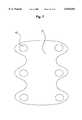
- FIG. 5Gis an alternate embodiment of the screw drive head.
- FIG. 5His an alternate embodiment of the screw drive head.
- FIG. 5Iis a top view of the screw head shown in cross-section in FIG. 5H.
- FIG. 5Jis a side view of a drive means.
- FIG. 5Kis an end-on view of the drive means shown in FIG. 5J.
- FIG. 5Lshows a pinching drive means in cross-section.
- FIG. 5Mis an end-on view of the driver means of FIG. 5K.
- FIGS. 6A-6Cis an exploded view of the driver means of FIGS. 5L and SM.
- FIG. 7shows a cortical bone fixation plate with screw holes machined therein.
- the method for preparing and using the interference screw of this inventioncomprises the steps of obtaining a fragment of bone from the cortex of an appropriate donor bone and machining the thread, tip and drive-head of the screw.
- FIG. 1Athere is shown a photograph of an exemplary embodiment of the bone interference screw of this invention, and in FIG. 1B, there is provided a schematic of the same embodiment of the screw, showing several of the key dimensions of the screw.
- the length of this screw, as shown in FIG. 1Bis about 25 mm, and the diameter, as shown in FIG. 1B, is about 7 mm.
- a square headis provided which matingly fits a square drive socket of an appropriate screw-driving implement.
- a terminuswhich may be inserted into a pre-drilled cavity.
- the threads of the screwpreferably cover approximately between about 75% and 95%, and most preferably about 85% of the length of the screw, with the remaining fraction of the screw being devoted to the drive-head.
- the drive-headmay have any shape that allows sufficient torque to be applied to the head of the screw to drive the screw into a pre-drilled cavity of appropriate diameter.
- the drive-headmay be square, as shown in FIGS. 1A and 1B, hexagonal, metric socket shaped or standard socket shaped.
- the headmay have a machined, recessed Allen-wrench, star headed driver, phillips head or slotted head purchase for torque application.
- the drive recessmay, for example, be that shown in U.S. Pat. No. 5,470,334, the disclosure of which is herein incorporated by reference, for receiving a rotatable driver.
- the threads of the screw of this inventionmay be of like dimensional arrangement to that shown in the U.S. Pat. No. 5,470,334.
- the drive and thread arrangement disclosed in U.S. Pat. No. 5,364,400is herein incorporated by reference as being acceptable and desirable for the bone interference screw of the present invention.
- the threadwill have a height of about 0.045 inches.
- the bone screw of this inventionmay have a diameter between about 4 mm and about 12 mm, for ACL implant fixation, and preferably being about 5 mm, 7 mm, 9 mm, 10 mm or 11 mm in diameter.
- the length of the bone screwmay be between about 8 mm and 70 mm, preferably being about 10 mm, 12 mm, 15 mm, 20 mm, 25 mm, 30 mm, or 40 mm in length.
- the same screwmay be used for soft tissue attachment, with or without the addition of a flange being incorporated into the design of the head portion.
- Bone screws of this invention having appropriate length and diametercould also be used to advantage and with greater strength in applications such as, for example, the vertebral fusion procedure described by J. M. Vich (Vich, 1985), or it may be used to affix any number of other implants. For these differing purposes, it will be recognized that diameters as small as 4 mm and as large as 30 mm may be appropriate.
- a consenting donori.e., a donor card or other form of acceptance to serve as a donor
- a consenting donori.e., a donor card or other form of acceptance to serve as a donor
- communicable diseases and pathogensincluding human immunodeficiency virus, cytomegalovirus, hepatitis B, hepatitis C and several other pathogens.
- the cortical sectionsare removed from linear aspects of the femur or from the anterior cortex of the tibia, and is preferably first machined into a dowel or "blank".
- a dowel of the cortical boneis then machined, preferably in a class 10 clean room, to the dimensions desired.
- the machiningis preferably conducted on a graduated die, a grinding wheel, a lathe, or machining tools may be specifically designed and adapted for this purpose. Specific tolerances for the screws and reproduceability of the product dimensions are important features for the successful use of such screws in the clinical setting.
- a threadis cut on the circumference of the screw and a head cut to allow an appropriate driving tool to screw the interference device into a cavity machined by a surgeon, for example, adjacent to a ligamentous implant.
- the forward end or tip of the screw which is to be inserted into a cavity formed by a surgeon adjacent the ligament or other implantis preferably fashioned by appropriate means known in the art, such as machining, to produce a tip of any desired geometry, such as a pointed tip, a rounded tip or a flush tip.
- a drive-headis machined, for example, by creating a square or hexagonal head.
- a square or hexagonal recessmay also be drilled into the screw. It will be recognized by those skilled in the art that a number of shapes and modes of driving the screw into its implant site may be used, without departing from the invention disclosed and claimed herein.
- the final machined productmay be stored, frozen or freeze-dried and vacuum sealed for later use.
- FIG. 5Athere is shown a number of preferred features in a bone interference screw of this invention.
- the blank's lengthis depicted by a first dimension 11, which is either in inches or is assigned a relative value of unity.
- a second dimension, 12is provided, representing approximately 0.85 of the length 11.
- a third dimension, 13, and a fourth dimension, 14,are each provided, each representing approximately 0.10 of the length 11.
- a fifth dimension, 12ais provided, representing the dimension 12 minus the dimensions 13 and 14.
- the forward end of the blank, 15, destined to become the "point" of the screw,has a tapered angle over the dimension 14, tapering from a diameter 16a of about 0.285 inches (which may also be assigned a relative value of unity and all other subsequently provided measurements being scaled appropriately) at point 16 to a diameter 17a of about 0.190 at point 17.
- a centerdrillon the cylindrical centerline.
- the tapering and centerdrill at point 21is shown in the head-on projection shown in FIG. 5B. This centerdrill is helpful in the machining of the screw.
- the centerdrill 21may be extended throughout the dimension 11 as a centerbore in the screw to provide a cannulated screw.
- the screwmay be guided into position by sliding the screw over a guide-wire, guide-pin or k-wire, all of which are conventional in the art.
- the centerbore of the cannulated screwneed be no greater in diameter than about 0.5-3 mm, to avoid weakening the screw.
- the tapering of the screw blank, as described,is important to avoid the production of "feathery" edges upon machining of the thread. Such feathering may be encountered if a uniformly cylindrical blank is used to machine the thread.
- FIG. 5Dthere is shown the screw after machining of the screw thread 22.
- the machined thread root diameter 23is about 0.190 across the entire dimension 12.
- the thread crest diameter 24 over the dimension 12ais about 0.280 after machining,
- the crest diameterdecreases over the dimensions 13 and 14.
- the screwwill preferably have a pitch of between about S threads per inch to about 40 threads per inch, and a diameter between about 2-15 mm, thereby defining the thread profile.
- pitchi.e., the distance 25a
- diameteri.e., the diameter of the threaded portion of the screw is tapered, such that, for example, a screw having a length of 10-12 mm has a diameter which tapers from about 12 mm down to about 6 mm at the tip end of the screw.
- FIG. 5Fthere is shown a preferred machined head shape, referred to herein as a "dog bone-shape," thus providing a “dog bone-head screw”.
- the diameteris machined to about 0.186 at dimension 26, and about 0.11 at dimension 27.
- No centerbore holeis shown as the cannulation is an optional albeit preferred embodiment.
- FIG. 5Gthere is shown an alternate machined head shape, referred to herein as a “twister” head having a pair of "wings", 33 which engage an appropriate drive means.
- FIG. 5Hthere is shown in cross-section a further head design, referred to herein as the "sunken groove” design. In this design a square groove 33 is drilled into the head of the screw.
- FIG. 5Ithere is shown the generally circular screw head with a square groove 33 drilled therein.
- FIG. 5Jis a side-view of the driver showing a shaft 28 which may be turned by a handle or other means at 29.
- a recessed drive slot 30is provided into which the dog bone-head or twister-head of the interference screw fits. Shown end-on in FIG. 5K are the drive slot, 30, and the shaft 28.
- the dog-bone shaped recess 30engages the dog bone-head of the screw, to apply rotating torque thereto.
- the drivermay be made from stainless steel, titanium or like material.
- the driveris modified as required to mate with a twister-shaped head by fashioning the recess 30 to accommodate this shape.
- a rigid mating square headed drive meansthat fits into the machined square groove provides ample torque to insert that screw.
- Attached to the outer shaft 28is an outer shaft handle 29 (not shown) and attached to the inner shaft 28a is an inner shaft handle 29a (not shown).
- an outer shaft insert 36is welded into place.
- the outer shaft insert 36is seen to have a pair of inwardly projecting driver lugs 37a and 37b.
- the ends of the forwardly projecting prongs 31are seen.
- This drive meansis prepared, as shown in FIGS. 6A through 6C, by preparing an outer shaft insert 36 with a pair of inwardly projecting driver lugs 37a and 37b.
- the inserthas an upper segment 38 with a first diameter that matches the diameter of the outer shaft 28.
- a second segment, 39has a smaller outer diameter than that of the outer shaft 28, but an inner diameter that is still large enough to accommodate the inner shaft 28a.
- the outer shaft insert 36may be inserted into the outer shaft 28 and welded at point 35, while the inner shaft 28a may be slid into the outer shaft 28 and still be rotatable therein.
- the outer shaft 28is shown in FIG. 6B, and the inner shaft 28a is shown in FIG. 6C.
- the forwardly projecting prongs 31optionally may have a serrated gripping surface 40.
- the bone-shaped head of a preferred screw of this inventionis inserted into the drive recess 30.
- the driver lugs 37a and 37bwill naturally engage the walls of the head of the screw.
- the outer shaft handle 29is used to hold the screw as the inner shaft handle 29a is rotated slightly ("torque applied" in FIG. 6C) so that the forwardly projecting prongs 31 engage the opposite sides of the screw head to create a pinching action.
- the pinching actionoccurs because the prongs 31 force the screw head against the driver lugs 37a and 37b.
- the driver lugs 37a and 37bthen are used to exert a torque in the opposite direction when the screw is screwed into the recipient's bone.
- the two handlesmay optimally interlock by an appropriate interlocking means to maintain the slight torque need to keep the screw head pinched.
- This embodiment of the driveris amenable to laporoscopic procedures where a screw may need to be "threaded” through tight spaces and orifices created in tissue.
- the same drive headmay be used to engage and drive the twister head screw.
- the bone screw of this inventionmay be used to secure a standard titanium or like fixation plate as in a vertebral fusion.
- FIG. 7there is shown a design for a novel cortical bone plate 41 machined from cortical bone of tibia.
- Several screw holes 42are shown in the plate.
- the interference screw of this inventionis screwed through the screw holes 42 to hold the plate in appropriate fixation position so that adjacent vertebrae may be fused.
- the screw holes 42be tapered, or counter-sunk so that once screwed into the screw hole, the screw head may be ground down so as to be flush with the surface of the bone plate.
- the head of the bone screwit is necessary for the head of the bone screw to have a greater diameter than that of the shaft of the bone screw or the hole in the bone plate, in order for the screw to provide a plate retention action.
- Thisis achieved by simply machining the bone screw to have a tapered head, as in a standard metal machine screw, such that once screwed into the bone plate, the top of the screw head is flush, thereby eliminating the need to grind down the screw-head.
- the entire fusion, including adjacent vertebrae, interference screws and bone plateall resorb over time as the fusion proceeds, and there is no need for subsequent removal of any hardware.
- the clinical advantages of the instant bone interference screware that it maintains bone stock, and there is no residual hardware as a result of use of the interference screw.
- a screw of this inventionhaving the appropriate dimensions is selected by the surgeon, based on the needs of the particular patient undergoing the implant.
- the screwis mounted on an appropriate driver which has a drive-head that mates with the head machined on the screw opposite the pointed, rounded or flush forward end.
- the screwis carefully driven partially into the cavity created for insertion of the implant and partially into the solid bone adjacent to the implant which is thereby locked into place.
- the screwis driven until the drive-head is flush with the implant site. Over a period of several months, as shown in FIG.
- seven allograft interference screwshaving dimensions of 7 mm by 25 mm were manufactured from the anterior cortex of fresh frozen human tibias.
- five conventional cannulated interference screws(7 mm by 25 mm) were used in parallel.
- Six fresh frozen human cadaveric femorawere used for the implants.
- Patellar bone-tendon-bone graftshaving a width of 11 mm with bone plugs of 25 mm length were implanted.
- a standard guide wirewas placed in the condyle of the distal femur and an 11 mm reamer was used to drill over the wire.
- a pathwaywas fashioned for the allograft screw parallel to the plug using sequential dilators from 3 to 6 mm.
- Self-tapping allograft screwswere placed with a custom socket driver for interference fit.
Landscapes
- Health & Medical Sciences (AREA)
- Orthopedic Medicine & Surgery (AREA)
- Life Sciences & Earth Sciences (AREA)
- Surgery (AREA)
- Medical Informatics (AREA)
- Engineering & Computer Science (AREA)
- Biomedical Technology (AREA)
- Heart & Thoracic Surgery (AREA)
- Nuclear Medicine, Radiotherapy & Molecular Imaging (AREA)
- Molecular Biology (AREA)
- Animal Behavior & Ethology (AREA)
- General Health & Medical Sciences (AREA)
- Public Health (AREA)
- Veterinary Medicine (AREA)
- Neurology (AREA)
- Prostheses (AREA)
Abstract
Description
TABLE 1 ______________________________________ Allograft screws (n = 7) 627 N ± 205 N Metallic screws (n = 5) 803 N ± 244 N ______________________________________
TABLE II ______________________________________ Mode of Failure Metal Screw Allograft Screw ______________________________________Screw pullout 3 3 Tendon-bone junction 1 3Clamp failure 1 1 ______________________________________
Claims (3)
Priority Applications (2)
| Application Number | Priority Date | Filing Date | Title |
|---|---|---|---|
| US09/098,916US6045554A (en) | 1996-07-16 | 1998-06-17 | Cortical bone interference screw |
| US09/866,105US20020052605A1 (en) | 1996-07-16 | 2001-05-24 | Cortical bone interference screw |
Applications Claiming Priority (2)
| Application Number | Priority Date | Filing Date | Title |
|---|---|---|---|
| US68701896A | 1996-07-16 | 1996-07-16 | |
| US09/098,916US6045554A (en) | 1996-07-16 | 1998-06-17 | Cortical bone interference screw |
Related Parent Applications (2)
| Application Number | Title | Priority Date | Filing Date |
|---|---|---|---|
| US68701896AContinuation | 1996-07-16 | 1996-07-16 | |
| US68701896ADivision | 1996-07-16 | 1996-07-16 |
Related Child Applications (1)
| Application Number | Title | Priority Date | Filing Date |
|---|---|---|---|
| US47753800AContinuation | 1996-07-16 | 2000-01-04 |
Publications (1)
| Publication Number | Publication Date |
|---|---|
| US6045554Atrue US6045554A (en) | 2000-04-04 |
Family
ID=24758681
Family Applications (1)
| Application Number | Title | Priority Date | Filing Date |
|---|---|---|---|
| US09/098,916Expired - LifetimeUS6045554A (en) | 1996-07-16 | 1998-06-17 | Cortical bone interference screw |
Country Status (1)
| Country | Link |
|---|---|
| US (1) | US6045554A (en) |
Cited By (115)
| Publication number | Priority date | Publication date | Assignee | Title |
|---|---|---|---|---|
| WO2000066011A1 (en)* | 1999-05-05 | 2000-11-09 | Michelson Gary K | Screws of cortical bone and method of manufacture thereof |
| US6283973B1 (en)* | 1998-12-30 | 2001-09-04 | Depuy Orthopaedics, Inc. | Strength fixation device |
| WO2001072233A1 (en)* | 2000-03-24 | 2001-10-04 | Tutogen Medical Gmbh | Interference screw made of bone material |
| US20010049560A1 (en)* | 1998-01-30 | 2001-12-06 | Paul David C. | Intervertebral allograft spacer |
| US20010053934A1 (en)* | 2000-06-09 | 2001-12-20 | Arthrex, Inc. | Method of ACL reconstruction using allograft bone cross pin implant |
| US20020016595A1 (en)* | 1999-05-05 | 2002-02-07 | Gary K. Michelson | Screws of cortical bone and method of manufacture thereof |
| WO2001080753A3 (en)* | 2000-04-20 | 2002-04-04 | Regeneration Tech Inc | Cortical bone interference screw |
| US6368322B1 (en)* | 1999-04-02 | 2002-04-09 | Osteotech, Inc. | Surgical bone screw |
| US20020091386A1 (en)* | 2001-01-05 | 2002-07-11 | Greg Martin | Pedicle screw assembly |
| US20020120270A1 (en)* | 2001-02-28 | 2002-08-29 | Hai Trieu | Flexible systems for spinal stabilization and fixation |
| US20020123750A1 (en)* | 2001-02-28 | 2002-09-05 | Lukas Eisermann | Woven orthopedic implants |
| WO2002069818A2 (en) | 2001-02-28 | 2002-09-12 | Synthes (U.S.A.) | Demineralized bone-derived implants |
| US20020143329A1 (en)* | 2001-03-30 | 2002-10-03 | Serhan Hassan A. | Intervertebral connection system |
| US20020183757A1 (en)* | 2001-06-04 | 2002-12-05 | Michelson Gary K. | Dynamic single-lock anterior cervical plate system having non-detachably fastened and moveable segments, instrumentation, and method for installation thereof |
| US20020183756A1 (en)* | 2001-06-04 | 2002-12-05 | Michelson Gary K. | Dynamic, modular, single-lock anterior cervical plate system, having assembleable and moveable segments, instrumentation, and method for installation thereof |
| US20020183755A1 (en)* | 2001-06-04 | 2002-12-05 | Michelson Gary K. | Dynamic anterior cervical plate system having moveable segments, instrumentation, and method for installation thereof |
| US20020188296A1 (en)* | 2001-06-06 | 2002-12-12 | Michelson Gary K. | Dynamic, modular, multilock anterior cervical plate system having detachably fastened assembleable and moveable segments, instrumentation, and method for installation thereof |
| US6494883B1 (en)* | 2000-05-26 | 2002-12-17 | Bret A. Ferree | Bone reinforcers |
| US20030036800A1 (en)* | 2000-07-13 | 2003-02-20 | Meredith Thomas L. | Composite bone material implant and method |
| US6527773B1 (en)* | 1999-10-07 | 2003-03-04 | Osteotech, Inc. | Cervical dowel and insertion tool |
| US20030060828A1 (en)* | 2001-06-06 | 2003-03-27 | Michelson Gary K. | Dynamic multilock anterior cervical plate system having non-detachably fastened and moveable segments, instrumentation, and method for installation thereof |
| US6547564B1 (en)* | 1998-07-17 | 2003-04-15 | Astra Aktiebolag | Bone implant having circumferentially oriented roughness |
| US20030074076A1 (en)* | 1999-10-08 | 2003-04-17 | Ferree Bret A. | Artificial intervertebral disc replacements with endplates |
| US20030074002A1 (en)* | 2001-10-12 | 2003-04-17 | West Hugh S. | Interference screws having increased proximal diameter |
| US20030191536A1 (en)* | 1999-10-08 | 2003-10-09 | Ferree Bret A. | Artificial intervertebral disc replacements incorporating reinforced wall sections |
| US6652585B2 (en) | 2001-02-28 | 2003-11-25 | Sdgi Holdings, Inc. | Flexible spine stabilization system |
| US20030229350A1 (en)* | 1995-08-22 | 2003-12-11 | Kay David B. | Open helical organic tissue anchor having recessible head and method of making the organic tissue anchor |
| US20040044409A1 (en)* | 1999-12-30 | 2004-03-04 | Alfaro Arthur A. | Intervertebral implants |
| US20040088053A1 (en)* | 2002-10-30 | 2004-05-06 | Hassan Serhan | Regenerative implants for stabilizing the spine and devices for attachment of said implants |
| US20040138748A1 (en)* | 2000-03-22 | 2004-07-15 | Synthes (Usa) | Plugs for filling bony defects |
| US20040172019A1 (en)* | 1999-10-08 | 2004-09-02 | Ferree Bret A. | Reinforcers for artificial disc replacement methods and apparatus |
| US20040186573A1 (en)* | 1999-10-08 | 2004-09-23 | Ferree Bret A. | Annulus fibrosis augmentation methods and apparatus |
| WO2004049900A3 (en)* | 2002-12-04 | 2004-12-02 | Sung-Jin Choi | Method for producing bone fracture fixation device with absorption delaying property |
| US6833005B1 (en) | 2001-02-02 | 2004-12-21 | John P. Mantas | Ligament graft system and method |
| US20040260396A1 (en)* | 1999-10-08 | 2004-12-23 | Ferree Bret A. | Artificial disc and joint replacements with modular cushioning components |
| US20050010298A1 (en)* | 2003-05-22 | 2005-01-13 | St. Francis Medical Technologies, Inc. | Cervical interspinous process distraction implant and method of implantation |
| US6875215B2 (en) | 2002-02-15 | 2005-04-05 | John Stanley Taras | Distraction pin for fracture fixation |
| US20050107880A1 (en)* | 2001-12-05 | 2005-05-19 | Osteotech, Inc. | Spinal intervertebral implant, interconnections for such implant and processes for making |
| US20050143740A1 (en)* | 2000-10-20 | 2005-06-30 | Morris John W. | Implant retaining device |
| US20050197638A1 (en)* | 2004-03-03 | 2005-09-08 | Six-O, Ltd. | Device for collecting surgical material |
| US20050240182A1 (en)* | 1997-01-02 | 2005-10-27 | St. Francis Medical Technologies, Inc. | Supplemental spine fixation device and method |
| US20050245929A1 (en)* | 2004-04-28 | 2005-11-03 | St. Francis Medical Technologies, Inc. | System and method for an interspinous process implant as a supplement to a spine stabilization implant |
| US20050256582A1 (en)* | 1999-10-08 | 2005-11-17 | Ferree Bret A | Spinal implants, including devices that reduce pressure on the annulus fibrosis |
| US20060036258A1 (en)* | 2004-06-08 | 2006-02-16 | St. Francis Medical Technologies, Inc. | Sizing distractor and method for implanting an interspinous implant between adjacent spinous processes |
| US20060084981A1 (en)* | 2004-10-20 | 2006-04-20 | Endius Incorporated | Apparatus for connecting a longitudinal member to a bone portion |
| US20060089718A1 (en)* | 2003-05-22 | 2006-04-27 | St. Francis Medical Technologies, Inc. | Interspinous process implant and method of implantation |
| US20060122612A1 (en)* | 2000-04-04 | 2006-06-08 | Justin Daniel F | Orthopedic screw and method |
| US20060145826A1 (en)* | 2002-04-19 | 2006-07-06 | Donnelly Corporation, A Corporation Of The State Of Michigan | Vehicle imaging system |
| US20060271194A1 (en)* | 2005-03-22 | 2006-11-30 | St. Francis Medical Technologies, Inc. | Interspinous process implant having deployable wing as an adjunct to spinal fusion and method of implantation |
| WO2007002914A1 (en)* | 2005-06-29 | 2007-01-04 | Ethicon, Inc. | Medical fixation devices with improved torsional drive head |
| US20070093830A1 (en)* | 2002-10-29 | 2007-04-26 | St. Francis Medical Technologies, Inc. | Interspinous process apparatus and method with a selectably expandable spacer |
| US7300465B2 (en) | 1998-01-30 | 2007-11-27 | Synthes (U.S.A.) | Intervertebral allograft spacer |
| US20080058819A1 (en)* | 1999-11-15 | 2008-03-06 | Wolf Eugene M | Bioabsorbable interference screw for endosteal fixation of ligaments |
| US20080097610A1 (en)* | 2006-09-02 | 2008-04-24 | Guyer Richard D | Implantable intervertebral fusion device |
| US20080108990A1 (en)* | 2006-11-02 | 2008-05-08 | St. Francis Medical Technologies, Inc. | Interspinous process implant having a fixed wing and a deployable wing and method of implantation |
| US20080255622A1 (en)* | 2007-04-13 | 2008-10-16 | Depuy Spine, Inc. | Facet fixation and fusion screw and washer assembly and method of use |
| US20080255666A1 (en)* | 2007-04-13 | 2008-10-16 | Depuy Spine, Inc. | Facet fixation and fusion wedge and method of use |
| US20080255618A1 (en)* | 2007-04-13 | 2008-10-16 | Depuy Spine, Inc. | Articulating facet fusion screw |
| US20090012620A1 (en)* | 2007-07-06 | 2009-01-08 | Jim Youssef | Implantable Cervical Fusion Device |
| US20090131986A1 (en)* | 2007-11-19 | 2009-05-21 | David Lee | Method and apparatus for spinal facet joint fusion using irregularly shaped cortical bone implants |
| US20090157082A1 (en)* | 2007-08-11 | 2009-06-18 | Meredith Thomas L | Portable Bone Grinder |
| USD595855S1 (en) | 2008-11-25 | 2009-07-07 | Orthopedic Development Corporation | Bone plug |
| US7591851B2 (en) | 2004-12-13 | 2009-09-22 | Kyphon Sarl | Inter-cervical facet implant and method |
| US20090248592A1 (en)* | 2000-10-20 | 2009-10-01 | Reinhold Schmieding | Method of selling procedure specific allografts and associated instrumentation |
| US20100049326A1 (en)* | 2007-02-12 | 2010-02-25 | Petersen Kenneth C | Joint revision implant |
| US20100094355A1 (en)* | 2008-10-13 | 2010-04-15 | Rockford Orthopaedic Sports Medicine Services, Llc | Variable tension post fixation |
| US7749252B2 (en) | 2005-03-21 | 2010-07-06 | Kyphon Sarl | Interspinous process implant having deployable wing and method of implantation |
| US7758619B2 (en) | 1997-01-02 | 2010-07-20 | Kyphon SÀRL | Spinous process implant with tethers |
| US7763050B2 (en) | 2004-12-13 | 2010-07-27 | Warsaw Orthopedic, Inc. | Inter-cervical facet implant with locking screw and method |
| US7833246B2 (en) | 2002-10-29 | 2010-11-16 | Kyphon SÀRL | Interspinous process and sacrum implant and method |
| US7909853B2 (en) | 2004-09-23 | 2011-03-22 | Kyphon Sarl | Interspinous process implant including a binder and method of implantation |
| US7959652B2 (en) | 2005-04-18 | 2011-06-14 | Kyphon Sarl | Interspinous process implant having deployable wings and method of implantation |
| US8012209B2 (en) | 2004-09-23 | 2011-09-06 | Kyphon Sarl | Interspinous process implant including a binder, binder aligner and method of implantation |
| US8070778B2 (en) | 2003-05-22 | 2011-12-06 | Kyphon Sarl | Interspinous process implant with slide-in distraction piece and method of implantation |
| US8133261B2 (en) | 2007-02-26 | 2012-03-13 | Depuy Spine, Inc. | Intra-facet fixation device and method of use |
| US8333985B2 (en) | 2004-01-27 | 2012-12-18 | Warsaw Orthopedic, Inc. | Non-glycerol stabilized bone graft |
| US8425530B2 (en) | 2004-12-13 | 2013-04-23 | Warsaw Orthopedic, Inc. | Apparatus for sizing a facet joint |
| US20130110173A1 (en)* | 2011-10-28 | 2013-05-02 | Warsaw Orthopedic, Inc. | Attachment mechanism for material and bone |
| USRE44800E1 (en) | 1998-07-17 | 2014-03-11 | Astrazeneca Ab | Dental implant |
| US8864827B2 (en) | 2000-05-01 | 2014-10-21 | Arthrosurface Inc. | System and method for joint resurface repair |
| US8926615B2 (en) | 2002-12-03 | 2015-01-06 | Arthrosurface, Inc. | System and method for retrograde procedure |
| US8961614B2 (en) | 2004-11-22 | 2015-02-24 | Arthrosurface, Inc. | Articular surface implant and delivery system |
| US9044277B2 (en) | 2010-07-12 | 2015-06-02 | DePuy Synthes Products, Inc. | Pedicular facet fusion screw with plate |
| US9044343B2 (en) | 2002-12-03 | 2015-06-02 | Arthrosurface Incorporated | System for articular surface replacement |
| US9055955B2 (en) | 2000-05-01 | 2015-06-16 | Arthrosurface Inc. | Bone resurfacing system and method |
| US9066716B2 (en) | 2011-03-30 | 2015-06-30 | Arthrosurface Incorporated | Suture coil and suture sheath for tissue repair |
| US9173692B1 (en)* | 2012-06-15 | 2015-11-03 | Stc.Unm | Composite metal and bone orthopedic fixation devices |
| US20150335368A1 (en)* | 2012-12-17 | 2015-11-26 | Auger JOSHUA | A twist-drivable pin assembly |
| US9204873B2 (en) | 2000-05-01 | 2015-12-08 | Arthrosurface Incorporated | System and method for joint resurface repair |
| US9283076B2 (en) | 2009-04-17 | 2016-03-15 | Arthrosurface Incorporated | Glenoid resurfacing system and method |
| US9351745B2 (en) | 2003-02-24 | 2016-05-31 | Arthrosurface Incorporated | Trochlear resurfacing system and method |
| US9358029B2 (en) | 2006-12-11 | 2016-06-07 | Arthrosurface Incorporated | Retrograde resection apparatus and method |
| US9357989B2 (en) | 2000-05-01 | 2016-06-07 | Arthrosurface Incorporated | System and method for joint resurface repair |
| US9468448B2 (en) | 2012-07-03 | 2016-10-18 | Arthrosurface Incorporated | System and method for joint resurfacing and repair |
| US9492200B2 (en) | 2013-04-16 | 2016-11-15 | Arthrosurface Incorporated | Suture system and method |
| US9521999B2 (en) | 2005-09-13 | 2016-12-20 | Arthrex, Inc. | Fully-threaded bioabsorbable suture anchor |
| US9526493B2 (en) | 1999-02-02 | 2016-12-27 | Arthrex, Inc. | Suture anchor with insert-molded rigid member |
| US9610109B2 (en) | 2011-08-16 | 2017-04-04 | Howmedica Osteonics Corp. | Wedge shaped fracture fixation devices and methods for using the same |
| US9622739B2 (en) | 2004-04-06 | 2017-04-18 | Arthrex, Inc. | Suture anchor |
| US9662126B2 (en) | 2009-04-17 | 2017-05-30 | Arthrosurface Incorporated | Glenoid resurfacing system and method |
| US9706986B2 (en) | 2000-06-22 | 2017-07-18 | Arthrex, Inc. | Knotless suture and tissue securing method |
| US9861492B2 (en) | 2014-03-07 | 2018-01-09 | Arthrosurface Incorporated | Anchor for an implant assembly |
| USD816469S1 (en)* | 2017-01-11 | 2018-05-01 | Marshall Lee Toomey | Deep groove screw |
| WO2019034522A1 (en)* | 2017-08-14 | 2019-02-21 | Surgebright Gmbh | BONE SCREW |
| US10624752B2 (en) | 2006-07-17 | 2020-04-21 | Arthrosurface Incorporated | Tibial resurfacing system and method |
| US10624748B2 (en) | 2014-03-07 | 2020-04-21 | Arthrosurface Incorporated | System and method for repairing articular surfaces |
| US10945743B2 (en) | 2009-04-17 | 2021-03-16 | Arthrosurface Incorporated | Glenoid repair system and methods of use thereof |
| USD921479S1 (en)* | 2018-11-27 | 2021-06-08 | International Life Sciences LLC | Eyelet interference screw |
| US11160663B2 (en) | 2017-08-04 | 2021-11-02 | Arthrosurface Incorporated | Multicomponent articular surface implant |
| US20220096239A1 (en)* | 2019-01-16 | 2022-03-31 | Surgebright Gmbh | Bone transplant |
| US11478358B2 (en) | 2019-03-12 | 2022-10-25 | Arthrosurface Incorporated | Humeral and glenoid articular surface implant systems and methods |
| US11607319B2 (en) | 2014-03-07 | 2023-03-21 | Arthrosurface Incorporated | System and method for repairing articular surfaces |
| US11712276B2 (en) | 2011-12-22 | 2023-08-01 | Arthrosurface Incorporated | System and method for bone fixation |
| USD1003702S1 (en)* | 2022-08-22 | 2023-11-07 | Anika Therapeutics, Inc. | Suture anchor |
| US12251495B2 (en) | 2021-09-27 | 2025-03-18 | Thomas Matthew Industries, Inc. | Bone grinder promoting bone osteoinductivity |
Citations (19)
| Publication number | Priority date | Publication date | Assignee | Title |
|---|---|---|---|---|
| US34871A (en)* | 1862-04-08 | Improvement in cooking-stoves | ||
| US55524A (en)* | 1866-06-12 | Improvement in nicking screw-heads | ||
| US846981A (en)* | 1906-09-17 | 1907-03-12 | James H Claiborne Jr | Screw. |
| US1330098A (en)* | 1919-05-16 | 1920-02-10 | Nat Acme Co | Machine-screw |
| US2570465A (en)* | 1949-08-01 | 1951-10-09 | Joseph S Lundholm | Means for fixation of hip fractures |
| US3470786A (en)* | 1965-07-01 | 1969-10-07 | Martins Boerge | Turnable devices |
| US4171662A (en)* | 1976-12-20 | 1979-10-23 | Wright Line Inc. | Security screw |
| US4450835A (en)* | 1981-02-20 | 1984-05-29 | Howmedica, Inc. | Method and system for inserting a surgical wire |
| US4537185A (en)* | 1983-06-10 | 1985-08-27 | Denis P. Stednitz | Cannulated fixation screw |
| US4605414A (en)* | 1984-06-06 | 1986-08-12 | John Czajka | Reconstruction of a cruciate ligament |
| US4877020A (en)* | 1984-11-30 | 1989-10-31 | Vich Jose M O | Apparatus for bone graft |
| US4950270A (en)* | 1989-02-03 | 1990-08-21 | Boehringer Mannheim Corporation | Cannulated self-tapping bone screw |
| US5282802A (en)* | 1990-02-07 | 1994-02-01 | Mahony Iii Thomas H | Method of securing a tendon graft with an interference fixation screw |
| US5360448A (en)* | 1991-10-07 | 1994-11-01 | Thramann Jeffrey J | Porous-coated bone screw for securing prosthesis |
| US5364400A (en)* | 1992-02-14 | 1994-11-15 | American Cyanamid Co. | Interference implant |
| US5378101A (en)* | 1992-12-22 | 1995-01-03 | Textron Inc. | Tamper-proof drive system based upon multi-lobular configuration |
| US5383878A (en)* | 1990-09-04 | 1995-01-24 | Hip Developments Pty Ltd. | Surgical screw |
| USRE34871E (en) | 1989-05-15 | 1995-03-07 | Mcguire; David A. | Process of endosteal fixation of a ligament |
| US5470334A (en)* | 1991-03-05 | 1995-11-28 | Linvatec Corporation | Bioabsorbable interference bone fixation screw |
- 1998
- 1998-06-17USUS09/098,916patent/US6045554A/ennot_activeExpired - Lifetime
Patent Citations (19)
| Publication number | Priority date | Publication date | Assignee | Title |
|---|---|---|---|---|
| US34871A (en)* | 1862-04-08 | Improvement in cooking-stoves | ||
| US55524A (en)* | 1866-06-12 | Improvement in nicking screw-heads | ||
| US846981A (en)* | 1906-09-17 | 1907-03-12 | James H Claiborne Jr | Screw. |
| US1330098A (en)* | 1919-05-16 | 1920-02-10 | Nat Acme Co | Machine-screw |
| US2570465A (en)* | 1949-08-01 | 1951-10-09 | Joseph S Lundholm | Means for fixation of hip fractures |
| US3470786A (en)* | 1965-07-01 | 1969-10-07 | Martins Boerge | Turnable devices |
| US4171662A (en)* | 1976-12-20 | 1979-10-23 | Wright Line Inc. | Security screw |
| US4450835A (en)* | 1981-02-20 | 1984-05-29 | Howmedica, Inc. | Method and system for inserting a surgical wire |
| US4537185A (en)* | 1983-06-10 | 1985-08-27 | Denis P. Stednitz | Cannulated fixation screw |
| US4605414A (en)* | 1984-06-06 | 1986-08-12 | John Czajka | Reconstruction of a cruciate ligament |
| US4877020A (en)* | 1984-11-30 | 1989-10-31 | Vich Jose M O | Apparatus for bone graft |
| US4950270A (en)* | 1989-02-03 | 1990-08-21 | Boehringer Mannheim Corporation | Cannulated self-tapping bone screw |
| USRE34871E (en) | 1989-05-15 | 1995-03-07 | Mcguire; David A. | Process of endosteal fixation of a ligament |
| US5282802A (en)* | 1990-02-07 | 1994-02-01 | Mahony Iii Thomas H | Method of securing a tendon graft with an interference fixation screw |
| US5383878A (en)* | 1990-09-04 | 1995-01-24 | Hip Developments Pty Ltd. | Surgical screw |
| US5470334A (en)* | 1991-03-05 | 1995-11-28 | Linvatec Corporation | Bioabsorbable interference bone fixation screw |
| US5360448A (en)* | 1991-10-07 | 1994-11-01 | Thramann Jeffrey J | Porous-coated bone screw for securing prosthesis |
| US5364400A (en)* | 1992-02-14 | 1994-11-15 | American Cyanamid Co. | Interference implant |
| US5378101A (en)* | 1992-12-22 | 1995-01-03 | Textron Inc. | Tamper-proof drive system based upon multi-lobular configuration |
Non-Patent Citations (30)
| Title |
|---|
| Albee, F.H. (1940) "Bone Graft Surgery in Disease, Injury and Deformity" D. Appleton-Century Company, Inc., pp. 20-23. |
| Albee, F.H. (1940) Bone Graft Surgery in Disease, Injury and Deformity D. Appleton Century Company, Inc., pp. 20 23.* |
| Albee, F.H. et al. (1940) "The General Principles of Bone Grafting" Bone Graft Surgery in Disease, Injury and Deformity, Appleton-Century Company, Inc. (publisher), pages xi-xv; 1-31; 48-107; and 210-227. |
| Albee, F.H. et al. (1940) The General Principles of Bone Grafting Bone Graft Surgery in Disease, Injury and Deformity, Appleton Century Company, Inc. (publisher), pages xi xv; 1 31; 48 107; and 210 227.* |
| Barrett, G.R. et al. (1995) "Endobutton Button Endoscopic Fixation Technique in Anterior Cruciate Ligament Reconstruction" Anthroscopy: The Journal of Arthroscopic and Related Surgery 11(3):340-343. |
| Barrett, G.R. et al. (1995) Endobutton Button Endoscopic Fixation Technique in Anterior Cruciate Ligament Reconstruction Anthroscopy: The Journal of Arthroscopic and Related Surgery 11(3):340 343.* |
| Boden, S.D. et al. (1995) "Biologic Enhancement of Spinal Fusion" Spine 20(24S):113S-123S. |
| Boden, S.D. et al. (1995) Biologic Enhancement of Spinal Fusion Spine 20(24S):113S 123S.* |
| Buchardt, H. (1983) "The Biology of Bone Graft Repair" Clinical Orthopaedic and Related Research 174:28-42. |
| Buchardt, H. (1983) The Biology of Bone Graft Repair Clinical Orthopaedic and Related Research 174:28 42.* |
| Firer, P. (1991) "In Vivo Effectiveness of Interference Screw Fixation for Bone-Ligament-Bone Anterior Curciate Ligament Reconstruction" American Journal of Sports Medicine 19(5):538-539. |
| Firer, P. (1991) In Vivo Effectiveness of Interference Screw Fixation for Bone Ligament Bone Anterior Curciate Ligament Reconstruction American Journal of Sports Medicine 19(5):538 539.* |
| Kohn, D., C. Rose (1994) "Primary Stability of Interference Screw Fixation" The American Journal of Sports Medicine 22(3):334-338. |
| Kohn, D., C. Rose (1994) Primary Stability of Interference Screw Fixation The American Journal of Sports Medicine 22(3):334 338.* |
| Kousa, P. et al. (1995) "Fixation Strength of a Biodegradable Screw in Anterior Cruciate Ligament Reconstruction" The Journal of Bone and Joint Surgery 77-B(6):901-905. |
| Kousa, P. et al. (1995) Fixation Strength of a Biodegradable Screw in Anterior Cruciate Ligament Reconstruction The Journal of Bone and Joint Surgery 77 B(6):901 905.* |
| Lambert, K., Vascularized Patellar Tendon Graft with Rigid . . . Clinical Orthopaedics 172:85 89, 1983.* |
| Lambert, K., Vascularized Patellar Tendon Graft with Rigid . . . Clinical Orthopaedics 172:85-89, 1983. |
| Lemos, M.J. et al. (1995) "Assessment of Initial Fixation of Endoscopic Interference Femoral Screws with Divergent and Parallel Placement" Arthroscopy: The Journal of Arthroscopic and Related Surgery 11(1):37-41. |
| Lemos, M.J. et al. (1995) Assessment of Initial Fixation of Endoscopic Interference Femoral Screws with Divergent and Parallel Placement Arthroscopy: The Journal of Arthroscopic and Related Surgery 11(1):37 41.* |
| Matthews, L.S., S.R. Soffer (1989) "Pitfalls in the Use of Interference Screws for Anterior Cruciate Ligament Reconstruction: Brief Report" Anthroscopy: The Journal of Arthroscopic and Related Surgery 5(3):225-226. |
| Matthews, L.S., S.R. Soffer (1989) Pitfalls in the Use of Interference Screws for Anterior Cruciate Ligament Reconstruction: Brief Report Anthroscopy: The Journal of Arthroscopic and Related Surgery 5(3):225 226.* |
| Meister, K. et al. (1996) "Allograft Bone Interference Screws in ACL Reconstructions" American Academy of Orthopaedic Surgeons 63rd Annual Meeting, Feb. 22-26, 1996 (abstract). |
| Meister, K. et al. (1996) Allograft Bone Interference Screws in ACL Reconstructions American Academy of Orthopaedic Surgeons 63rd Annual Meeting, Feb. 22 26, 1996 (abstract).* |
| Obwegeser, J., Bioconvertible screws made of allogenic . . . J. Cranio Maxillo Facial Surgery 22:63 75, 1994.* |
| Obwegeser, J., Bioconvertible screws made of allogenic . . . J. Cranio-Maxillo-Facial Surgery 22:63-75, 1994. |
| Vich, J.M.O. (1985) "Anterior cervical interbody fusion with threaded cylindrical bone" J. Neurosurg. 63:750-753. |
| Vich, J.M.O. (1985) Anterior cervical interbody fusion with threaded cylindrical bone J. Neurosurg. 63:750 753.* |
| Zou, D. et al. (1991) "Interference Screw Fixation of Cervical Grafts: A Biomechanical Study of a New Method of Cervical Fixation" Journal of Spinal Disorders 4(2):168-176. |
| Zou, D. et al. (1991) Interference Screw Fixation of Cervical Grafts: A Biomechanical Study of a New Method of Cervical Fixation Journal of Spinal Disorders 4(2):168 176.* |
Cited By (262)
| Publication number | Priority date | Publication date | Assignee | Title |
|---|---|---|---|---|
| US20030229350A1 (en)* | 1995-08-22 | 2003-12-11 | Kay David B. | Open helical organic tissue anchor having recessible head and method of making the organic tissue anchor |
| US7189251B2 (en)* | 1995-08-22 | 2007-03-13 | Orthohelix Surgical Designs, Inc. | Open helical organic tissue anchor having recessible head and method of making the organic tissue anchor |
| US7621939B2 (en) | 1997-01-02 | 2009-11-24 | Kyphon Sarl | Supplemental spine fixation device and method |
| US7955356B2 (en) | 1997-01-02 | 2011-06-07 | Kyphon Sarl | Laterally insertable interspinous process implant |
| US7918877B2 (en) | 1997-01-02 | 2011-04-05 | Kyphon Sarl | Lateral insertion method for spinous process spacer with deployable member |
| US20050240182A1 (en)* | 1997-01-02 | 2005-10-27 | St. Francis Medical Technologies, Inc. | Supplemental spine fixation device and method |
| US7828822B2 (en) | 1997-01-02 | 2010-11-09 | Kyphon SÀRL | Spinous process implant |
| US20070055246A1 (en)* | 1997-01-02 | 2007-03-08 | St. Francis Medical Technologies, Inc. | Spine distraction implant and method |
| US7758619B2 (en) | 1997-01-02 | 2010-07-20 | Kyphon SÀRL | Spinous process implant with tethers |
| US20010049560A1 (en)* | 1998-01-30 | 2001-12-06 | Paul David C. | Intervertebral allograft spacer |
| US6986788B2 (en) | 1998-01-30 | 2006-01-17 | Synthes (U.S.A.) | Intervertebral allograft spacer |
| US7300465B2 (en) | 1998-01-30 | 2007-11-27 | Synthes (U.S.A.) | Intervertebral allograft spacer |
| US6547564B1 (en)* | 1998-07-17 | 2003-04-15 | Astra Aktiebolag | Bone implant having circumferentially oriented roughness |
| US20030120279A1 (en)* | 1998-07-17 | 2003-06-26 | Stig Hansson | Implant having circumferentially oriented roughness |
| US7517218B2 (en) | 1998-07-17 | 2009-04-14 | Astra Tech Ab | Implant having circumferentially oriented roughness |
| USRE44800E1 (en) | 1998-07-17 | 2014-03-11 | Astrazeneca Ab | Dental implant |
| US8333590B2 (en) | 1998-07-17 | 2012-12-18 | Astra Tech Ab | Implant having circumferentially oriented roughness |
| US8277219B2 (en) | 1998-07-17 | 2012-10-02 | Astra Tech Ab | Implant having circumferentially oriented roughness |
| US7959440B2 (en) | 1998-07-17 | 2011-06-14 | Astra Tech Ab | Implant having circumferentially oriented roughness |
| US7264470B2 (en) | 1998-07-17 | 2007-09-04 | Astrazeneca Ab | Implant having circumferentially oriented roughness |
| US7883336B2 (en) | 1998-07-17 | 2011-02-08 | Astra Tech Ab | Implant having circumferentially oriented roughness |
| US20080020347A1 (en)* | 1998-07-17 | 2008-01-24 | Astrazeneca Ab | Implant |
| US6283973B1 (en)* | 1998-12-30 | 2001-09-04 | Depuy Orthopaedics, Inc. | Strength fixation device |
| US9526493B2 (en) | 1999-02-02 | 2016-12-27 | Arthrex, Inc. | Suture anchor with insert-molded rigid member |
| US6368322B1 (en)* | 1999-04-02 | 2002-04-09 | Osteotech, Inc. | Surgical bone screw |
| US7931840B2 (en) | 1999-05-05 | 2011-04-26 | Warsaw Orthopedic, Inc. | Method for preparing a spinal implant |
| US7094239B1 (en)* | 1999-05-05 | 2006-08-22 | Sdgi Holdings, Inc. | Screws of cortical bone and method of manufacture thereof |
| US7063701B2 (en) | 1999-05-05 | 2006-06-20 | Sdgi Holdings, Inc. | Screws of cortical bone having a trailing end configured to cooperatively engage an implant |
| US8323543B2 (en) | 1999-05-05 | 2012-12-04 | Warsaw Orthopedic, Inc. | Method for preparing an implant of cortical bone |
| US20050033433A1 (en)* | 1999-05-05 | 2005-02-10 | Michelson Gary K. | Implant having upper and lower extended members and method for use thereof |
| US7063702B2 (en) | 1999-05-05 | 2006-06-20 | Sdgi Holdings, Inc. | Screws of cortical bone and method of manufacture thereof |
| US20020016595A1 (en)* | 1999-05-05 | 2002-02-07 | Gary K. Michelson | Screws of cortical bone and method of manufacture thereof |
| WO2000066011A1 (en)* | 1999-05-05 | 2000-11-09 | Michelson Gary K | Screws of cortical bone and method of manufacture thereof |
| US20110125267A1 (en)* | 1999-05-05 | 2011-05-26 | Michelson Gary K | Method for preparing an implant of cortical bone |
| US6527773B1 (en)* | 1999-10-07 | 2003-03-04 | Osteotech, Inc. | Cervical dowel and insertion tool |
| US20050256582A1 (en)* | 1999-10-08 | 2005-11-17 | Ferree Bret A | Spinal implants, including devices that reduce pressure on the annulus fibrosis |
| US20060235535A1 (en)* | 1999-10-08 | 2006-10-19 | Ferree Bret A | Artificial disc and joint replacements with modular cushioning components |
| US7201774B2 (en) | 1999-10-08 | 2007-04-10 | Ferree Bret A | Artificial intervertebral disc replacements incorporating reinforced wall sections |
| US7060100B2 (en) | 1999-10-08 | 2006-06-13 | Ferree Bret A | Artificial disc and joint replacements with modular cushioning components |
| US20040172019A1 (en)* | 1999-10-08 | 2004-09-02 | Ferree Bret A. | Reinforcers for artificial disc replacement methods and apparatus |
| US7201776B2 (en) | 1999-10-08 | 2007-04-10 | Ferree Bret A | Artificial intervertebral disc replacements with endplates |
| US20030191536A1 (en)* | 1999-10-08 | 2003-10-09 | Ferree Bret A. | Artificial intervertebral disc replacements incorporating reinforced wall sections |
| US20040186573A1 (en)* | 1999-10-08 | 2004-09-23 | Ferree Bret A. | Annulus fibrosis augmentation methods and apparatus |
| US20040260396A1 (en)* | 1999-10-08 | 2004-12-23 | Ferree Bret A. | Artificial disc and joint replacements with modular cushioning components |
| US20030074076A1 (en)* | 1999-10-08 | 2003-04-17 | Ferree Bret A. | Artificial intervertebral disc replacements with endplates |
| US20080058819A1 (en)* | 1999-11-15 | 2008-03-06 | Wolf Eugene M | Bioabsorbable interference screw for endosteal fixation of ligaments |
| US7662185B2 (en) | 1999-12-30 | 2010-02-16 | Osteotech, Inc. | Intervertebral implants |
| US20040044409A1 (en)* | 1999-12-30 | 2004-03-04 | Alfaro Arthur A. | Intervertebral implants |
| US20040138748A1 (en)* | 2000-03-22 | 2004-07-15 | Synthes (Usa) | Plugs for filling bony defects |
| US6767369B2 (en) | 2000-03-22 | 2004-07-27 | Synthes (Usa) | Plugs for filling bony defects |
| WO2001072233A1 (en)* | 2000-03-24 | 2001-10-04 | Tutogen Medical Gmbh | Interference screw made of bone material |
| US20030144668A1 (en)* | 2000-03-24 | 2003-07-31 | Matthias Lowel | Interference screw made of bone material |
| US7578836B2 (en)* | 2000-04-04 | 2009-08-25 | Depuy Mitek | Orthopedic screw and method |
| US20060122612A1 (en)* | 2000-04-04 | 2006-06-08 | Justin Daniel F | Orthopedic screw and method |
| WO2001080753A3 (en)* | 2000-04-20 | 2002-04-04 | Regeneration Tech Inc | Cortical bone interference screw |
| US9055955B2 (en) | 2000-05-01 | 2015-06-16 | Arthrosurface Inc. | Bone resurfacing system and method |
| US9357989B2 (en) | 2000-05-01 | 2016-06-07 | Arthrosurface Incorporated | System and method for joint resurface repair |
| US8864827B2 (en) | 2000-05-01 | 2014-10-21 | Arthrosurface Inc. | System and method for joint resurface repair |
| US9204873B2 (en) | 2000-05-01 | 2015-12-08 | Arthrosurface Incorporated | System and method for joint resurface repair |
| US6494883B1 (en)* | 2000-05-26 | 2002-12-17 | Bret A. Ferree | Bone reinforcers |
| US6623524B2 (en)* | 2000-06-09 | 2003-09-23 | Arthrex, Inc. | Method for anterior cruciate ligament reconstruction using cross-pin implant with eyelet |
| US20040059415A1 (en)* | 2000-06-09 | 2004-03-25 | Reinhold Schmieding | Method of ACL reconstruction using allograft bone cross pin implant |
| US20010053934A1 (en)* | 2000-06-09 | 2001-12-20 | Arthrex, Inc. | Method of ACL reconstruction using allograft bone cross pin implant |
| US10716556B2 (en) | 2000-06-22 | 2020-07-21 | Arthtrex, Inc. | Knotless tissue fixation assembly |
| US9706986B2 (en) | 2000-06-22 | 2017-07-18 | Arthrex, Inc. | Knotless suture and tissue securing method |
| US9775599B2 (en) | 2000-06-22 | 2017-10-03 | Arthrex, Inc. | Knotless tissue fixation assembly |
| US10709436B2 (en) | 2000-06-22 | 2020-07-14 | Arthrex, Inc. | Graft fixation using a plug against suture |
| US7001551B2 (en) | 2000-07-13 | 2006-02-21 | Allograft Research Technologies, Inc. | Method of forming a composite bone material implant |
| US20030036800A1 (en)* | 2000-07-13 | 2003-02-20 | Meredith Thomas L. | Composite bone material implant and method |
| US8672980B2 (en) | 2000-10-20 | 2014-03-18 | Warsaw Orthopedic, Inc. | Implant retaining device |
| US7780708B2 (en) | 2000-10-20 | 2010-08-24 | Osteotech, Inc. | Implant retaining device |
| US20110054614A1 (en)* | 2000-10-20 | 2011-03-03 | Morris John W | Implant retaining device |
| US20050143740A1 (en)* | 2000-10-20 | 2005-06-30 | Morris John W. | Implant retaining device |
| US20090248592A1 (en)* | 2000-10-20 | 2009-10-01 | Reinhold Schmieding | Method of selling procedure specific allografts and associated instrumentation |
| US20020183748A1 (en)* | 2001-01-05 | 2002-12-05 | Stryker Spine | Pedicle screw assembly and methods therefor |
| US20020091386A1 (en)* | 2001-01-05 | 2002-07-11 | Greg Martin | Pedicle screw assembly |
| US8894692B2 (en) | 2001-01-05 | 2014-11-25 | Stryker France | Pedicle screw assembly and methods therefor |
| US6858030B2 (en)* | 2001-01-05 | 2005-02-22 | Stryker Spine | Pedicle screw assembly and methods therefor |
| USRE42932E1 (en)* | 2001-01-05 | 2011-11-15 | Stryker France | Pedicle screw assembly and methods therefor |
| US6833005B1 (en) | 2001-02-02 | 2004-12-21 | John P. Mantas | Ligament graft system and method |
| US20050043733A1 (en)* | 2001-02-28 | 2005-02-24 | Lukas Eisermann | Woven orthopedic implants |
| US7229441B2 (en) | 2001-02-28 | 2007-06-12 | Warsaw Orthopedic, Inc. | Flexible systems for spinal stabilization and fixation |
| US20050119749A1 (en)* | 2001-02-28 | 2005-06-02 | Lange Eric C. | Flexible spine stabilization systems |
| US7041138B2 (en) | 2001-02-28 | 2006-05-09 | Sdgi Holdings, Inc. | Flexible spine stabilization systems |
| US6652585B2 (en) | 2001-02-28 | 2003-11-25 | Sdgi Holdings, Inc. | Flexible spine stabilization system |
| US20060200140A1 (en)* | 2001-02-28 | 2006-09-07 | Lange Eric C | Flexible spine stabilization systems |
| US20040078082A1 (en)* | 2001-02-28 | 2004-04-22 | Lange Eric C. | Flexible spine stabilization systems |
| US20080132950A1 (en)* | 2001-02-28 | 2008-06-05 | Lange Eric C | Flexible spine stabilization systems |
| US6827743B2 (en) | 2001-02-28 | 2004-12-07 | Sdgi Holdings, Inc. | Woven orthopedic implants |
| US6776800B2 (en) | 2001-02-28 | 2004-08-17 | Synthes (U.S.A.) | Implants formed with demineralized bone |
| US7341601B2 (en) | 2001-02-28 | 2008-03-11 | Warsaw Orthopedic, Inc. | Woven orthopedic implants |
| US20060009846A1 (en)* | 2001-02-28 | 2006-01-12 | Hai Trieu | Flexible systems for spinal stabilization and fixation |
| US7326249B2 (en) | 2001-02-28 | 2008-02-05 | Warsaw Orthopedic, Inc. | Flexible spine stabilization systems |
| WO2002069818A2 (en) | 2001-02-28 | 2002-09-12 | Synthes (U.S.A.) | Demineralized bone-derived implants |
| US20020123750A1 (en)* | 2001-02-28 | 2002-09-05 | Lukas Eisermann | Woven orthopedic implants |
| US20020120270A1 (en)* | 2001-02-28 | 2002-08-29 | Hai Trieu | Flexible systems for spinal stabilization and fixation |
| WO2002069818A3 (en)* | 2001-02-28 | 2004-04-08 | Synthes Usa | Demineralized bone-derived implants |
| US6852128B2 (en) | 2001-02-28 | 2005-02-08 | Sdgi Holdings, Inc. | Flexible spine stabilization systems |
| US20020143329A1 (en)* | 2001-03-30 | 2002-10-03 | Serhan Hassan A. | Intervertebral connection system |
| US7344539B2 (en) | 2001-03-30 | 2008-03-18 | Depuy Acromed, Inc. | Intervertebral connection system |
| US20090259226A1 (en)* | 2001-06-04 | 2009-10-15 | Michelson Gary K | Method for installation of dynamic, single-lock anterior cervical plate system having non-detachably fastened and moveable segments |
| US7985224B2 (en) | 2001-06-04 | 2011-07-26 | Warsaw Orthopedic, Inc. | Method for installation of dynamic, single-lock anterior cervical plate system having non-detachably fastened and moveable segments |
| US20110054528A1 (en)* | 2001-06-04 | 2011-03-03 | Michelson Gary K | Dynamic plate system having moveable segments |
| US20040181229A1 (en)* | 2001-06-04 | 2004-09-16 | Michelson Gary K. | Instrumentation for use with dynamic single-lock anterior cervical plate system having non-detachably fastened and moveable segments |
| US7186256B2 (en)* | 2001-06-04 | 2007-03-06 | Warsaw Orthopedic, Inc. | Dynamic, modular, single-lock anterior cervical plate system having assembleable and movable segments |
| US20050216010A1 (en)* | 2001-06-04 | 2005-09-29 | Michelson Gary K | Method for installation of dynamic, single-lock anterior cervical plate system having non-detachably fastened and moveable segments |
| US20050085816A1 (en)* | 2001-06-04 | 2005-04-21 | Michelson Gary K. | Method for installation of dynamic anterior cervical plate system having moveable segments |
| US20040181226A1 (en)* | 2001-06-04 | 2004-09-16 | Michelson Gary K. | Method for installing dynamic, modular, single-lock anterior cervical plate system having assembleable and moveable segments |
| US7118573B2 (en)* | 2001-06-04 | 2006-10-10 | Sdgi Holdings, Inc. | Dynamic anterior cervical plate system having moveable segments, instrumentation, and method for installation thereof |
| US7097645B2 (en) | 2001-06-04 | 2006-08-29 | Sdgi Holdings, Inc. | Dynamic single-lock anterior cervical plate system having non-detachably fastened and moveable segments |
| US8834533B2 (en) | 2001-06-04 | 2014-09-16 | Warsaw Orthopedic, Inc. | Dynamic plate system having moveable segments |
| US7824432B2 (en) | 2001-06-04 | 2010-11-02 | Warsaw Orthopedic, Inc. | Method for installation of dynamic anterior cervical plate system having moveable segments |
| US7399301B2 (en) | 2001-06-04 | 2008-07-15 | Warsaw Orthopedic, Inc. | Instrumentation for use with dynamic single-lock anterior cervical plate system having non-detachably fastened and moveable segments |
| US20020183756A1 (en)* | 2001-06-04 | 2002-12-05 | Michelson Gary K. | Dynamic, modular, single-lock anterior cervical plate system, having assembleable and moveable segments, instrumentation, and method for installation thereof |
| US20020183755A1 (en)* | 2001-06-04 | 2002-12-05 | Michelson Gary K. | Dynamic anterior cervical plate system having moveable segments, instrumentation, and method for installation thereof |
| US20050027297A1 (en)* | 2001-06-04 | 2005-02-03 | Michelson Gary K. | Dynamic, modular, single-lock anterior cervical plate system having assembleable and moveable segments and instrumentation for installation thereof |
| US7547306B2 (en) | 2001-06-04 | 2009-06-16 | Warsaw Orthopedic, Inc. | Method for installation of dynamic, single-lock anterior cervical plate system having non-detachably fastened and moveable segments |
| US7811285B2 (en) | 2001-06-04 | 2010-10-12 | Warsaw Orthopedic, Inc. | Dynamic, modular, single-lock anterior cervical plate system having assembleable and moveable segments and instrumentation for installation thereof |
| US7112202B2 (en) | 2001-06-04 | 2006-09-26 | Warsaw Orthopedic, Inc. | Method for installing dynamic, modular, single-lock anterior cervical plate system having assembleable and moveable segments |
| US20020183757A1 (en)* | 2001-06-04 | 2002-12-05 | Michelson Gary K. | Dynamic single-lock anterior cervical plate system having non-detachably fastened and moveable segments, instrumentation, and method for installation thereof |
| US20030060828A1 (en)* | 2001-06-06 | 2003-03-27 | Michelson Gary K. | Dynamic multilock anterior cervical plate system having non-detachably fastened and moveable segments, instrumentation, and method for installation thereof |
| US7041105B2 (en) | 2001-06-06 | 2006-05-09 | Sdgi Holdings, Inc. | Dynamic, modular, multilock anterior cervical plate system having detachably fastened assembleable and moveable segments |
| US20020188296A1 (en)* | 2001-06-06 | 2002-12-12 | Michelson Gary K. | Dynamic, modular, multilock anterior cervical plate system having detachably fastened assembleable and moveable segments, instrumentation, and method for installation thereof |
| US7115130B2 (en) | 2001-06-06 | 2006-10-03 | Warsaw Orthopedic, Inc. | Method for installing dynamic, modular, multilock anterior cervical plate system having detachably fastened assembleable and moveable segments |
| US20050192576A1 (en)* | 2001-06-06 | 2005-09-01 | Michelson Gary K. | Method for installing dynamic multilock anterior cervical plate system having detachably fastened and moveable segments |
| US20040186476A1 (en)* | 2001-06-06 | 2004-09-23 | Michelson Gary K. | Method for installing dynamic, modular, multilock anterior cervical plate system having detachably fastened assembleable and moveable segments |
| US7803157B2 (en) | 2001-06-06 | 2010-09-28 | Warsaw Orthopedic, Inc. | Dynamic, modular, multilock anterior cervical plate system having detachably fastened assembleable and moveable segments and instrumentation for installation thereof |
| US20050216009A1 (en)* | 2001-06-06 | 2005-09-29 | Michelson Gary K | Instrumentation for use with dynamic multilock anterior cervical plate system having non-detachably fastened and moveable segments |
| US20050027298A1 (en)* | 2001-06-06 | 2005-02-03 | Michelson Gary K. | Dynamic, modular, multilock anterior cervical plate system having detachably fastened assembleable and moveable segments and instrumentation for installation thereof |
| US7044952B2 (en) | 2001-06-06 | 2006-05-16 | Sdgi Holdings, Inc. | Dynamic multilock anterior cervical plate system having non-detachably fastened and moveable segments |
| US7704250B2 (en) | 2001-06-06 | 2010-04-27 | Warsaw Orthopedic, Inc. | Instrumentation for use with dynamic multilock anterior cervical plate system having non-detachably fastened and moveable segments |
| US7621943B2 (en) | 2001-06-06 | 2009-11-24 | Warsaw Orthopedic, Inc. | Method for installing dynamic multilock anterior cervical plate system having detachably fastened and moveable segments |
| US20030074002A1 (en)* | 2001-10-12 | 2003-04-17 | West Hugh S. | Interference screws having increased proximal diameter |
| US6953463B2 (en)* | 2001-10-12 | 2005-10-11 | Hs West Investments, Llc | Interference screws having increased proximal diameter |
| US7726002B2 (en) | 2001-12-05 | 2010-06-01 | Osteotech, Inc. | Processes for making spinal intervertebral implant, interconnections for such implant |
| US20050107880A1 (en)* | 2001-12-05 | 2005-05-19 | Osteotech, Inc. | Spinal intervertebral implant, interconnections for such implant and processes for making |
| US20050165402A1 (en)* | 2002-02-15 | 2005-07-28 | Taras John S. | Cannulated distraction pin for fracture fixation |
| US6875215B2 (en) | 2002-02-15 | 2005-04-05 | John Stanley Taras | Distraction pin for fracture fixation |
| US20060145826A1 (en)* | 2002-04-19 | 2006-07-06 | Donnelly Corporation, A Corporation Of The State Of Michigan | Vehicle imaging system |
| US20070106385A1 (en)* | 2002-10-29 | 2007-05-10 | St. Francis Medical Technologies, Inc. | Interspinous process apparatus and method with a selectably expandable spacer |
| US7833246B2 (en) | 2002-10-29 | 2010-11-16 | Kyphon SÀRL | Interspinous process and sacrum implant and method |
| US7803190B2 (en) | 2002-10-29 | 2010-09-28 | Kyphon SÀRL | Interspinous process apparatus and method with a selectably expandable spacer |
| US7476251B2 (en) | 2002-10-29 | 2009-01-13 | Kyphon Sarl | Interspinous process apparatus and method with a selectably expandable spacer |
| US20070093830A1 (en)* | 2002-10-29 | 2007-04-26 | St. Francis Medical Technologies, Inc. | Interspinous process apparatus and method with a selectably expandable spacer |
| US7682392B2 (en) | 2002-10-30 | 2010-03-23 | Depuy Spine, Inc. | Regenerative implants for stabilizing the spine and devices for attachment of said implants |
| US20040088053A1 (en)* | 2002-10-30 | 2004-05-06 | Hassan Serhan | Regenerative implants for stabilizing the spine and devices for attachment of said implants |
| US10076343B2 (en) | 2002-12-03 | 2018-09-18 | Arthrosurface Incorporated | System for articular surface replacement |
| US9044343B2 (en) | 2002-12-03 | 2015-06-02 | Arthrosurface Incorporated | System for articular surface replacement |
| US8926615B2 (en) | 2002-12-03 | 2015-01-06 | Arthrosurface, Inc. | System and method for retrograde procedure |
| WO2004049900A3 (en)* | 2002-12-04 | 2004-12-02 | Sung-Jin Choi | Method for producing bone fracture fixation device with absorption delaying property |
| US10624749B2 (en) | 2003-02-24 | 2020-04-21 | Arthrosurface Incorporated | Trochlear resurfacing system and method |
| US11337819B2 (en) | 2003-02-24 | 2022-05-24 | Arthrosurface Incorporated | Trochlear resurfacing system and method |
| US9931211B2 (en) | 2003-02-24 | 2018-04-03 | Arthrosurface Incorporated | Trochlear resurfacing system and method |
| US9351745B2 (en) | 2003-02-24 | 2016-05-31 | Arthrosurface Incorporated | Trochlear resurfacing system and method |
| US7695513B2 (en) | 2003-05-22 | 2010-04-13 | Kyphon Sarl | Distractible interspinous process implant and method of implantation |
| US20060089718A1 (en)* | 2003-05-22 | 2006-04-27 | St. Francis Medical Technologies, Inc. | Interspinous process implant and method of implantation |
| US8070778B2 (en) | 2003-05-22 | 2011-12-06 | Kyphon Sarl | Interspinous process implant with slide-in distraction piece and method of implantation |
| US8048117B2 (en) | 2003-05-22 | 2011-11-01 | Kyphon Sarl | Interspinous process implant and method of implantation |
| US7549999B2 (en) | 2003-05-22 | 2009-06-23 | Kyphon Sarl | Interspinous process distraction implant and method of implantation |
| US20050010298A1 (en)* | 2003-05-22 | 2005-01-13 | St. Francis Medical Technologies, Inc. | Cervical interspinous process distraction implant and method of implantation |
| US8333985B2 (en) | 2004-01-27 | 2012-12-18 | Warsaw Orthopedic, Inc. | Non-glycerol stabilized bone graft |
| US7195617B2 (en) | 2004-03-03 | 2007-03-27 | Six-O, Ltd. | Device for collecting surgical material |
| US20050197638A1 (en)* | 2004-03-03 | 2005-09-08 | Six-O, Ltd. | Device for collecting surgical material |
| US10537319B2 (en) | 2004-04-06 | 2020-01-21 | Arthrex, Inc. | Suture anchor |
| US9622739B2 (en) | 2004-04-06 | 2017-04-18 | Arthrex, Inc. | Suture anchor |
| US20050245929A1 (en)* | 2004-04-28 | 2005-11-03 | St. Francis Medical Technologies, Inc. | System and method for an interspinous process implant as a supplement to a spine stabilization implant |
| US7524324B2 (en) | 2004-04-28 | 2009-04-28 | Kyphon Sarl | System and method for an interspinous process implant as a supplement to a spine stabilization implant |
| US20060036258A1 (en)* | 2004-06-08 | 2006-02-16 | St. Francis Medical Technologies, Inc. | Sizing distractor and method for implanting an interspinous implant between adjacent spinous processes |
| US8012209B2 (en) | 2004-09-23 | 2011-09-06 | Kyphon Sarl | Interspinous process implant including a binder, binder aligner and method of implantation |
| US7909853B2 (en) | 2004-09-23 | 2011-03-22 | Kyphon Sarl | Interspinous process implant including a binder and method of implantation |
| US20060084981A1 (en)* | 2004-10-20 | 2006-04-20 | Endius Incorporated | Apparatus for connecting a longitudinal member to a bone portion |
| US8366747B2 (en) | 2004-10-20 | 2013-02-05 | Zimmer Spine, Inc. | Apparatus for connecting a longitudinal member to a bone portion |
| US8961614B2 (en) | 2004-11-22 | 2015-02-24 | Arthrosurface, Inc. | Articular surface implant and delivery system |
| US8100944B2 (en) | 2004-12-13 | 2012-01-24 | Kyphon Sarl | Inter-cervical facet implant and method for preserving the tissues surrounding the facet joint |
| US7601170B2 (en) | 2004-12-13 | 2009-10-13 | Kyphon Sarl | Inter-cervical facet implant and method |
| US7776090B2 (en) | 2004-12-13 | 2010-08-17 | Warsaw Orthopedic, Inc. | Inter-cervical facet implant and method |
| US7763050B2 (en) | 2004-12-13 | 2010-07-27 | Warsaw Orthopedic, Inc. | Inter-cervical facet implant with locking screw and method |
| US7591851B2 (en) | 2004-12-13 | 2009-09-22 | Kyphon Sarl | Inter-cervical facet implant and method |
| US8425530B2 (en) | 2004-12-13 | 2013-04-23 | Warsaw Orthopedic, Inc. | Apparatus for sizing a facet joint |
| US7749252B2 (en) | 2005-03-21 | 2010-07-06 | Kyphon Sarl | Interspinous process implant having deployable wing and method of implantation |
| US7931674B2 (en) | 2005-03-21 | 2011-04-26 | Kyphon Sarl | Interspinous process implant having deployable wing and method of implantation |
| US20060271194A1 (en)* | 2005-03-22 | 2006-11-30 | St. Francis Medical Technologies, Inc. | Interspinous process implant having deployable wing as an adjunct to spinal fusion and method of implantation |
| US7959652B2 (en) | 2005-04-18 | 2011-06-14 | Kyphon Sarl | Interspinous process implant having deployable wings and method of implantation |
| US7727235B2 (en) | 2005-06-29 | 2010-06-01 | Ethicon, Inc. | Medical fixation devices with improved torsional drive head |
| US10213195B2 (en) | 2005-06-29 | 2019-02-26 | Ethicon, Inc. | Medical fixation devices with improved torsional drive head |
| US20100222795A1 (en)* | 2005-06-29 | 2010-09-02 | Ethicon, Inc. | Medical fixation devices with improved torsional drive head |
| WO2007002914A1 (en)* | 2005-06-29 | 2007-01-04 | Ethicon, Inc. | Medical fixation devices with improved torsional drive head |
| US20070021750A1 (en)* | 2005-07-20 | 2007-01-25 | Shluzas Alan E | Apparatus for connecting a longitudinal member to a bone portion |
| US8167911B2 (en) | 2005-07-20 | 2012-05-01 | Zimmer Spine, Inc. | Apparatus for connecting a longitudinal member to a bone portion |
| US9521999B2 (en) | 2005-09-13 | 2016-12-20 | Arthrex, Inc. | Fully-threaded bioabsorbable suture anchor |
| US10595847B2 (en) | 2005-09-13 | 2020-03-24 | Arthrex, Inc. | Fully-threaded bioabsorbable suture anchor |
| US12064104B2 (en) | 2005-09-13 | 2024-08-20 | Arthrex, Inc. | Fully-threaded bioabsorbable suture anchor |
| US11324493B2 (en) | 2005-09-13 | 2022-05-10 | Arthrex, Inc. | Fully-threaded bioabsorbable suture anchor |
| US11471289B2 (en) | 2006-07-17 | 2022-10-18 | Arthrosurface Incorporated | Tibial resurfacing system and method |
| US10624752B2 (en) | 2006-07-17 | 2020-04-21 | Arthrosurface Incorporated | Tibial resurfacing system and method |
| US20080097610A1 (en)* | 2006-09-02 | 2008-04-24 | Guyer Richard D | Implantable intervertebral fusion device |
| US8043377B2 (en) | 2006-09-02 | 2011-10-25 | Osprey Biomedical, Inc. | Implantable intervertebral fusion device |
| US20080108990A1 (en)* | 2006-11-02 | 2008-05-08 | St. Francis Medical Technologies, Inc. | Interspinous process implant having a fixed wing and a deployable wing and method of implantation |
| US10045788B2 (en) | 2006-12-11 | 2018-08-14 | Arthrosurface Incorporated | Retrograde resection apparatus and method |
| US10959740B2 (en) | 2006-12-11 | 2021-03-30 | Arthrosurface Incorporated | Retrograde resection apparatus and method |
| US9358029B2 (en) | 2006-12-11 | 2016-06-07 | Arthrosurface Incorporated | Retrograde resection apparatus and method |
| US8372157B2 (en) | 2007-02-12 | 2013-02-12 | Warsaw Orthopedic, Inc. | Joint revision implant |
| US20100049326A1 (en)* | 2007-02-12 | 2010-02-25 | Petersen Kenneth C | Joint revision implant |
| US8133261B2 (en) | 2007-02-26 | 2012-03-13 | Depuy Spine, Inc. | Intra-facet fixation device and method of use |
| US20080255618A1 (en)* | 2007-04-13 | 2008-10-16 | Depuy Spine, Inc. | Articulating facet fusion screw |
| US20080255666A1 (en)* | 2007-04-13 | 2008-10-16 | Depuy Spine, Inc. | Facet fixation and fusion wedge and method of use |
| US20080255622A1 (en)* | 2007-04-13 | 2008-10-16 | Depuy Spine, Inc. | Facet fixation and fusion screw and washer assembly and method of use |
| US8043334B2 (en) | 2007-04-13 | 2011-10-25 | Depuy Spine, Inc. | Articulating facet fusion screw |
| US8197513B2 (en) | 2007-04-13 | 2012-06-12 | Depuy Spine, Inc. | Facet fixation and fusion wedge and method of use |
| US8894685B2 (en) | 2007-04-13 | 2014-11-25 | DePuy Synthes Products, LLC | Facet fixation and fusion screw and washer assembly and method of use |
| US20090012620A1 (en)* | 2007-07-06 | 2009-01-08 | Jim Youssef | Implantable Cervical Fusion Device |
| US20090157082A1 (en)* | 2007-08-11 | 2009-06-18 | Meredith Thomas L | Portable Bone Grinder |
| US8512342B2 (en) | 2007-08-11 | 2013-08-20 | Thomas L. Meredith | Portable bone grinder |
| US8961571B2 (en) | 2007-11-19 | 2015-02-24 | David Lee | Method and apparatus for spinal facet joint fusion using irregularly shaped cortical bone implants |
| US20090131986A1 (en)* | 2007-11-19 | 2009-05-21 | David Lee | Method and apparatus for spinal facet joint fusion using irregularly shaped cortical bone implants |
| US20100100127A1 (en)* | 2008-10-13 | 2010-04-22 | Rockford Orthopaedic Sports Medicine Services, Llc | Variable tension post fixation |
| US8382799B2 (en) | 2008-10-13 | 2013-02-26 | Rockford Orthopaedic Sports Medicine Services, Llc | Variable tension post fixation |
| US20100094355A1 (en)* | 2008-10-13 | 2010-04-15 | Rockford Orthopaedic Sports Medicine Services, Llc | Variable tension post fixation |
| USD595855S1 (en) | 2008-11-25 | 2009-07-07 | Orthopedic Development Corporation | Bone plug |
| US9662126B2 (en) | 2009-04-17 | 2017-05-30 | Arthrosurface Incorporated | Glenoid resurfacing system and method |
| US10478200B2 (en) | 2009-04-17 | 2019-11-19 | Arthrosurface Incorporated | Glenoid resurfacing system and method |
| US11478259B2 (en) | 2009-04-17 | 2022-10-25 | Arthrosurface, Incorporated | Glenoid resurfacing system and method |
| US9283076B2 (en) | 2009-04-17 | 2016-03-15 | Arthrosurface Incorporated | Glenoid resurfacing system and method |
| US10945743B2 (en) | 2009-04-17 | 2021-03-16 | Arthrosurface Incorporated | Glenoid repair system and methods of use thereof |
| US9089372B2 (en) | 2010-07-12 | 2015-07-28 | DePuy Synthes Products, Inc. | Pedicular facet fusion screw with plate |
| US9044277B2 (en) | 2010-07-12 | 2015-06-02 | DePuy Synthes Products, Inc. | Pedicular facet fusion screw with plate |
| US9066716B2 (en) | 2011-03-30 | 2015-06-30 | Arthrosurface Incorporated | Suture coil and suture sheath for tissue repair |
| US9610109B2 (en) | 2011-08-16 | 2017-04-04 | Howmedica Osteonics Corp. | Wedge shaped fracture fixation devices and methods for using the same |
| US10499967B2 (en) | 2011-08-16 | 2019-12-10 | Howmedica Osteonics Corp. | Wedge shaped fracture fixation devices and methods for using the same |
| US20130110173A1 (en)* | 2011-10-28 | 2013-05-02 | Warsaw Orthopedic, Inc. | Attachment mechanism for material and bone |
| US11712276B2 (en) | 2011-12-22 | 2023-08-01 | Arthrosurface Incorporated | System and method for bone fixation |
| US9173692B1 (en)* | 2012-06-15 | 2015-11-03 | Stc.Unm | Composite metal and bone orthopedic fixation devices |
| US20160000489A1 (en)* | 2012-06-15 | 2016-01-07 | Stc.Unm | Composite Metal and Bone Orthopedic Fixation Devices |
| US10307172B2 (en) | 2012-07-03 | 2019-06-04 | Arthrosurface Incorporated | System and method for joint resurfacing and repair |
| US11191552B2 (en) | 2012-07-03 | 2021-12-07 | Arthrosurface, Incorporated | System and method for joint resurfacing and repair |
| US9468448B2 (en) | 2012-07-03 | 2016-10-18 | Arthrosurface Incorporated | System and method for joint resurfacing and repair |
| US20150335368A1 (en)* | 2012-12-17 | 2015-11-26 | Auger JOSHUA | A twist-drivable pin assembly |
| US11071574B2 (en) | 2012-12-17 | 2021-07-27 | Depuy Ireland Unlimited Company | Twist-drivable pin assembly |
| US9492200B2 (en) | 2013-04-16 | 2016-11-15 | Arthrosurface Incorporated | Suture system and method |
| US10695096B2 (en) | 2013-04-16 | 2020-06-30 | Arthrosurface Incorporated | Suture system and method |
| US11648036B2 (en) | 2013-04-16 | 2023-05-16 | Arthrosurface Incorporated | Suture system and method |
| US11083587B2 (en) | 2014-03-07 | 2021-08-10 | Arthrosurface Incorporated | Implant and anchor assembly |
| US11607319B2 (en) | 2014-03-07 | 2023-03-21 | Arthrosurface Incorporated | System and method for repairing articular surfaces |
| US9962265B2 (en) | 2014-03-07 | 2018-05-08 | Arthrosurface Incorporated | System and method for repairing articular surfaces |
| US9861492B2 (en) | 2014-03-07 | 2018-01-09 | Arthrosurface Incorporated | Anchor for an implant assembly |
| US10575957B2 (en) | 2014-03-07 | 2020-03-03 | Arthrosurface Incoporated | Anchor for an implant assembly |
| US11766334B2 (en) | 2014-03-07 | 2023-09-26 | Arthrosurface Incorporated | System and method for repairing articular surfaces |
| US10624748B2 (en) | 2014-03-07 | 2020-04-21 | Arthrosurface Incorporated | System and method for repairing articular surfaces |
| US9931219B2 (en) | 2014-03-07 | 2018-04-03 | Arthrosurface Incorporated | Implant and anchor assembly |
| US10624754B2 (en) | 2014-03-07 | 2020-04-21 | Arthrosurface Incorporated | System and method for repairing articular surfaces |
| USD816469S1 (en)* | 2017-01-11 | 2018-05-01 | Marshall Lee Toomey | Deep groove screw |
| US11160663B2 (en) | 2017-08-04 | 2021-11-02 | Arthrosurface Incorporated | Multicomponent articular surface implant |
| WO2019034522A1 (en)* | 2017-08-14 | 2019-02-21 | Surgebright Gmbh | BONE SCREW |
| CN110996821A (en)* | 2017-08-14 | 2020-04-10 | 祖尔格布莱特有限公司 | Bone screw |
| US11744624B2 (en)* | 2017-08-14 | 2023-09-05 | Surgebright Gmbh | Bone screw |
| USD921479S1 (en)* | 2018-11-27 | 2021-06-08 | International Life Sciences LLC | Eyelet interference screw |
| US20220096239A1 (en)* | 2019-01-16 | 2022-03-31 | Surgebright Gmbh | Bone transplant |
| US12239537B2 (en)* | 2019-01-16 | 2025-03-04 | Surgebright Gmbh | Bone transplant |
| US11478358B2 (en) | 2019-03-12 | 2022-10-25 | Arthrosurface Incorporated | Humeral and glenoid articular surface implant systems and methods |
| US12251495B2 (en) | 2021-09-27 | 2025-03-18 | Thomas Matthew Industries, Inc. | Bone grinder promoting bone osteoinductivity |
| USD1003702S1 (en)* | 2022-08-22 | 2023-11-07 | Anika Therapeutics, Inc. | Suture anchor |
| USD1042831S1 (en)* | 2022-08-22 | 2024-09-17 | Anika Therapeutics, Inc. | Suture anchor |
Similar Documents
| Publication | Publication Date | Title |
|---|---|---|
| US6045554A (en) | Cortical bone interference screw | |
| US20020052605A1 (en) | Cortical bone interference screw | |
| US6283973B1 (en) | Strength fixation device | |
| US11471203B2 (en) | Apparatus, system and method for fusion of bone | |
| JP4056092B2 (en) | Open-chamber type intervertebral spacer | |
| US7553313B2 (en) | Apparatus and method for preparing a spinal implant surgical site for receiving a spinal fusion implant | |
| US8034090B2 (en) | Tissue fixation device | |
| DE60316862T2 (en) | Fastening device for an implant | |
| US6506192B1 (en) | Allograft bone fixation screw | |
| US7914539B2 (en) | Tissue fixation device | |
| EP0929264B1 (en) | Apparatus and method for implant insertion | |
| CA2383809C (en) | Suture anchor | |
| US6033405A (en) | Apparatus and method for implant insertion | |
| US4950270A (en) | Cannulated self-tapping bone screw | |
| AU763735B2 (en) | Truncated open intervertebral spacers | |
| US7182781B1 (en) | Cervical tapered dowel | |
| EP1364617A2 (en) | Surgical drill and retractor | |
| US20020143343A1 (en) | Method and apparatus for spinal implant insertion | |
| US20020111680A1 (en) | Ratcheted bone dowel | |
| JP2002534211A5 (en) | ||
| JP2003250808A (en) | Combination body of implant fixing device | |
| DE60117474T2 (en) | Fixing system for an implant | |
| US20040153076A1 (en) | Ligament graft cage fixation device | |
| WO2001080753A2 (en) | Cortical bone interference screw |
Legal Events
| Date | Code | Title | Description |
|---|---|---|---|
| STCF | Information on status: patent grant | Free format text:PATENTED CASE | |
| FPAY | Fee payment | Year of fee payment:4 | |
| AS | Assignment | Owner name:UNIVERSITY OF FLORIDA TISSUE BANK, INC., FLORIDA Free format text:CORRECTIVE COVERSHEET TO CORRECT SERIAL NUMBER THAT WAS PREVIOUSLY RECORDED ON REEL 8134, FRAME 0168.;ASSIGNORS:DULEBOHN, DAVID H.;GROOMS, JAMES M.;CARTER, KEVIN;REEL/FRAME:015618/0719;SIGNING DATES FROM 19960710 TO 19960712 | |
| AS | Assignment | Owner name:REGENERATION TECHNOLOGIES, INC., FLORIDA Free format text:ASSIGNMENT OF ASSIGNORS INTEREST;ASSIGNORS:SOUTHEAST TISSUE ALLIANCE, INC.;UNIVERSITY OF FLORIDA ORTHOPAEDIC TISSUE BANK, INC.;UNIVERSITY OF FLORIDA TISSUE BANK, INC.;REEL/FRAME:015796/0186 Effective date:20050121 Owner name:REGENERATION TECHNOLOGIES, INC.,FLORIDA Free format text:ASSIGNMENT OF ASSIGNORS INTEREST;ASSIGNORS:SOUTHEAST TISSUE ALLIANCE, INC.;UNIVERSITY OF FLORIDA ORTHOPAEDIC TISSUE BANK, INC.;UNIVERSITY OF FLORIDA TISSUE BANK, INC.;REEL/FRAME:015796/0186 Effective date:20050121 | |
| FEPP | Fee payment procedure | Free format text:PAT HOLDER NO LONGER CLAIMS SMALL ENTITY STATUS, ENTITY STATUS SET TO UNDISCOUNTED (ORIGINAL EVENT CODE: STOL); ENTITY STATUS OF PATENT OWNER: LARGE ENTITY | |
| FPAY | Fee payment | Year of fee payment:8 | |
| AS | Assignment | Owner name:RTI BIOLOGICS, INC., FLORIDA Free format text:CHANGE OF NAME;ASSIGNOR:REGENERATION TECHNOLOGIES, INC.;REEL/FRAME:020690/0942 Effective date:20080227 Owner name:RTI BIOLOGICS, INC.,FLORIDA Free format text:CHANGE OF NAME;ASSIGNOR:REGENERATION TECHNOLOGIES, INC.;REEL/FRAME:020690/0942 Effective date:20080227 | |
| FPAY | Fee payment | Year of fee payment:12 | |
| AS | Assignment | Owner name:TD BANK, N.A., AS ADMINISTRATIVE AGENT, FLORIDA Free format text:SECURITY AGREEMENT;ASSIGNOR:RTI SURGICAL, INC.;REEL/FRAME:030888/0001 Effective date:20130716 | |
| AS | Assignment | Owner name:RTI SURGICAL, INC., FLORIDA Free format text:CHANGE OF NAME;ASSIGNOR:RTI BIOLOGICS, INC.;REEL/FRAME:031012/0159 Effective date:20130716 | |
| AS | Assignment | Owner name:REGENERATION TECHNOLOGIES, INC. (A DELAWARE CORPOR Free format text:MERGER;ASSIGNOR:REGENERATION TECHNOLOGIES, INC. (A FLORIDA CORPORATION);REEL/FRAME:031753/0334 Effective date:20000803 | |
| AS | Assignment | Owner name:RTI SURGICAL, INC., FLORIDA Free format text:RELEASE BY SECURED PARTY;ASSIGNOR:TD BANK, N.A., AS ADMINISTRATIVE AGENT;REEL/FRAME:046327/0184 Effective date:20180605 |