US6045552A - Spine fixation plate system - Google Patents
Spine fixation plate systemDownload PDFInfo
- Publication number
- US6045552A US6045552AUS09/040,632US4063298AUS6045552AUS 6045552 AUS6045552 AUS 6045552AUS 4063298 AUS4063298 AUS 4063298AUS 6045552 AUS6045552 AUS 6045552A
- Authority
- US
- United States
- Prior art keywords
- keel
- plate
- vertebra
- plate portion
- vertebrae
- Prior art date
- Legal status (The legal status is an assumption and is not a legal conclusion. Google has not performed a legal analysis and makes no representation as to the accuracy of the status listed.)
- Expired - Lifetime
Links
Images


Classifications
- A—HUMAN NECESSITIES
- A61—MEDICAL OR VETERINARY SCIENCE; HYGIENE
- A61B—DIAGNOSIS; SURGERY; IDENTIFICATION
- A61B17/00—Surgical instruments, devices or methods
- A61B17/56—Surgical instruments or methods for treatment of bones or joints; Devices specially adapted therefor
- A61B17/58—Surgical instruments or methods for treatment of bones or joints; Devices specially adapted therefor for osteosynthesis, e.g. bone plates, screws or setting implements
- A61B17/68—Internal fixation devices, including fasteners and spinal fixators, even if a part thereof projects from the skin
- A61B17/70—Spinal positioners or stabilisers, e.g. stabilisers comprising fluid filler in an implant
- A61B17/7059—Cortical plates
- A—HUMAN NECESSITIES
- A61—MEDICAL OR VETERINARY SCIENCE; HYGIENE
- A61B—DIAGNOSIS; SURGERY; IDENTIFICATION
- A61B17/00—Surgical instruments, devices or methods
- A61B17/16—Instruments for performing osteoclasis; Drills or chisels for bones; Trepans
- A61B17/1604—Chisels; Rongeurs; Punches; Stamps
- A—HUMAN NECESSITIES
- A61—MEDICAL OR VETERINARY SCIENCE; HYGIENE
- A61B—DIAGNOSIS; SURGERY; IDENTIFICATION
- A61B17/00—Surgical instruments, devices or methods
- A61B17/16—Instruments for performing osteoclasis; Drills or chisels for bones; Trepans
- A61B17/1662—Instruments for performing osteoclasis; Drills or chisels for bones; Trepans for particular parts of the body
- A61B17/1671—Instruments for performing osteoclasis; Drills or chisels for bones; Trepans for particular parts of the body for the spine
- A—HUMAN NECESSITIES
- A61—MEDICAL OR VETERINARY SCIENCE; HYGIENE
- A61B—DIAGNOSIS; SURGERY; IDENTIFICATION
- A61B17/00—Surgical instruments, devices or methods
- A61B17/56—Surgical instruments or methods for treatment of bones or joints; Devices specially adapted therefor
- A61B17/58—Surgical instruments or methods for treatment of bones or joints; Devices specially adapted therefor for osteosynthesis, e.g. bone plates, screws or setting implements
- A61B17/68—Internal fixation devices, including fasteners and spinal fixators, even if a part thereof projects from the skin
- A61B17/80—Cortical plates, i.e. bone plates; Instruments for holding or positioning cortical plates, or for compressing bones attached to cortical plates
- A61B17/809—Cortical plates, i.e. bone plates; Instruments for holding or positioning cortical plates, or for compressing bones attached to cortical plates with bone-penetrating elements, e.g. blades or prongs
Definitions
- the present inventionis related to fixation plates, and in particular, fixation plates which are applied to one or more vertebrae of a spinal column in order to immobilize and/or stabilize portions of the spinal column.
- plating devices and systemsare available in the art for purposes of remedying dysfunctional vertebrae and associated disks which make up the spinal column of a human or for that matter any mammal.
- These plating systemsgenerally include a bar having a plurality of apertures through which can be placed screws. The screws are adapted for insertion into selected vertebral bodies.
- a platecan be used to span a disk area in order to rigidly secure upper and lower vertebral bodies together, and/or the plate can span an entire vertebral body in order to rigidly secure a vertebral body located above the spanned vertebral body to a vertebral body located below the spanned vertebral body.
- pairs of plating systemscan be placed on opposite lateral sides of upper and lower vertebral bodies, which bracket an intermediate vertebral body. Lateral attachment methodologies are preferred due to the complication associated with both anterior and posterior approaches. Further, difficulty has been experienced with stabilizing vertebrae in the lower lumbar and upper sacrum region, and in particular, stabilizing the L5 and S1 vertebrae.
- the presently inventionis directed to a spine fixation plating system which overcomes the problems and design of the prior art.
- the spine fixation plating apparatus of the present inventionis used for immobilizing a first vertebra relative to a second vertebra.
- the spine fixation plating apparatusincludes a plate with a first plate portion adapted to be positioned adjacent to a first outer surface of a first vertebra and a second plating portion adapted to be positioned adjacent to a second outer surface of a second vertebra.
- the spine fixation plate systemfurther includes a keel extending at an angle from said plate, with said keel adapted to penetrate into at least one of the first and second vertebra.
- the keelextends from the first plate portion of the plate to the second plate portion of the plate.
- the keelincludes a first keel portion extending from the first plate portion and a second keel portion extending from the second plate portion.
- the first plate portionis disposed at less than a straight angle relative to the second plate portion, with a keel positioned in said less than a straight angle between the first plate portion and the second plate portion.
- a keelpositioned in said less than a straight angle between the first plate portion and the second plate portion.
- a second keelis located in a second angle which is opposite to the less than a straight angle and is located between the first plate portion and the second plate portion.
- the plateis separate from the keel and the plate includes keel ports.
- the keelsare positionable through the keel ports and into engagement with the plate in order to penetrate the vertebra.
- the keelis configured in order to enable it to be retained in the vertebra.
- the keelis substantially perpendicular to the plate.
- the method of the inventionis appropriate for immobilizing a first vertebra relative to a second vertebra, and includes the steps of accessing the first and second vertebrae and making a slot in at least one of the first and second vertebrae.
- the methodfurther includes inserting into the spine a spine fixation plate apparatus for immobilizing the first vertebra relative to the second vertebra, wherein the plate apparatus comprises a plate with a first plate portion adapted to be positioned adjacent to a first outer surface of the first vertebra and a second plate portion adapted to be positioned adjacent to a second outer surface of the second vertebra, and a keel extending at an angle from said plate, said keel adapted to penetrate into at least one of the first and second vertebrae.
- the accessing stepincludes accessing the first and second vertebra anteriorly.
- a further stepincludes making a slot with a template using a guide port and a cutter which can fit through the guide port, with the guide port positioned adjacent to a vertebra, in order to penetrate the vertebra.
- FIG. 1depicts a side view of an embodiment of the present invention.
- FIG. 2depicts an anterior view of the embodiment in FIG. 1 positioned on anterior surfaces of the L5 and S1 vertebrae.
- FIG. 3depicts the L5 and S1 vertebrae prepared for receiving the embodiment of the invention of FIG. 1.
- FIG. 4depicts a side view of another embodiment of the invention.
- FIG. 5depicts yet another side view of still a further embodiment of the invention.
- FIG. 6depicts inventive tools for use in implanting an apparatus of the present invention.
- FIG. 7depicts a side view of a further embodiment of the present invention.
- FIG. 8depicts a top perspective view of the embodiment of FIG. 7.
- FIGS. 9-15depict alternative keel designs which can be used with any of the embodiments of the present invention.
- FIGS. 16-22depicts still further alternative keel design which can be used with any of the embodiments of the present invention.
- FIG. 23depicts a side view of yet another embodiment of the present invention.
- FIG. 24depicts a top view of the embodiment of FIG. 23.
- FIG. 25depicts still a further embodiment of the present invention.
- FIG. 26depicts an anterior view of yet another embodiment of the present invention wherein the keels are removable.
- FIG. 27depicts an anterior view of the removable keel of FIGS. 26.
- FIG. 28depicts a posterior perspective view of the keel of FIG. 27.
- FIG. 29depicts yet a further embodiment of the invention which has similarities to the embodiment of FIG. 26.
- FIG. 30depicts an alternative plate which can be used with the embodiment of FIG. 26.
- FIG. 31depicts yet a further alternative plate which can be used with the embodiment of FIG. 26.
- FIGS. 32 and 33depict yet still further alternative embodiments of the plate which can be used with the embodiment of the invention of FIG. 26.
- FIG. 34depicts a side view of the embodiment of the invention which can immobilize a number of vertebrae.
- FIG. 35depicts a perspective view of the embodiment of FIG. 34.
- FIG. 36depicts yet a further embodiment of the present invention.
- FIGS. 37 and 38depict an end view and a perspective posterior view of yet a further embodiment of the present invention.
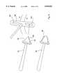
- the first embodiment of the inventionincludes a spine fixation plate apparatus 50 shown in FIGS. 1 and 2.
- the apparatus 50include a plate 52 which has a first plate portion 54 and a second plate portion 56.
- the first plate portion 54is adapted to be located adjacent a first vertebra, which as shown in the figure, is the L5 vertebra.
- the second plate portion 56is adapted to be located adjacent a second vertebra, which in FIG. 1 is the S1 vertebra.
- the first plate portion 54is positioned at less than a straight angle 58 from the second plate portion 56.
- the apparatus 50further includes a first keel 60 and a second keel 62.
- the first keel 60extends from the first plate portion 54, while second keel 62 extends from the second plate portion 56.
- first and second keel 60, 62are substantially perpendicular to the first and second plate portions 54, 56 respectively. It is to be understood that such keels can be disposed at angles other than perpendicular to the plate and be within the spirit and scope of the invention.
- the first keel 60additionally includes an aperture 65 and the second keel 62 includes an aperture 67. These apertures are provided in the respective keels in order to allow the vertebral bone to grow therethrough, firmly securing the apparatus 50 to the vertebrae. It is to be understood that other mechanisms such as differently shaped keels, different arrangements of apertures in the keels, and different keel surface treatments, and the like, can be utilized in order to secure the keel into the bone and provide for surfaces and contours for bone ingrowth.
- the first keel 60is adapted to be inserted in a slot in the upper vertebra, the L5 vertebra, while the second keel 62 is designed to be inserted into the lower vertebra, in this case, the S1 vertebra.
- the first keel 60is substantially triangularly shaped, and has a sharpened edge 64.
- the second keel 62is substantially rectangular and has a sharpened edge 66.
- Second keel 62could also be triangularly shaped and be within the scope of the invention.
- Each keelextends from the posterior side 68 of the plate 52.
- first and second screws 70, 72which are used to secure the apparatus 52 in place in the L5 and S1 vertebrae respectively.
- the apparatus 50is applied to the anterior outer surface 71 of the vertebral bodies of the L5 and S1 vertebrae and the screws are inserted into the vertebral bodies L5, S1 toward the posterior sides 73.
- the keelsare approximately 15 mm long so they project approximately 1/3 of the way into the vertebral body. In smaller people, the keels would be only about 10 mm-12 mm in length from the base of the keel located at the plate 52 to the tip of the keel.
- a bone graft 74has been inserted in the disk space between the L5 and S1 vertebrae.
- This graftis used to fuse the L5 vertebra to the S1 vertebra, while the plate apparatus 50 immobilizes and stabilizes the L5 vertebra relative to the S1 vertebra. It is to be understood that it is possible to use other methodologies instead of a bone graft in order to fuse the vertebra together.
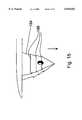
- FIG. 2depicts a plan view of the anterior side 76 of the plate 52.
- two additional screws 78, 80are used to secure the plate 52 to the L5 and S1 vertebrae respectfully.
- the screw 70, 72, 78, and 80are inserted through apertures provided in the plate 52.
- the plate 52is elongated along a central longitudinal axis 82.
- the plate 52also has a truncated end 84 and triangularly shaped end 86. Alternatively, the ends can also be rounded.
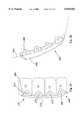
- FIG. 3depicts a site which has been prepared in the L5 and S1 vertebrae, as well as in the disk, prior to the insertion of the spine fixation plate apparatus 50 of the invention.
- a first slot 88 and a second slot 90are created in the vertebrae, and disk material is removed between the vertebrae in order to accommodate the plate apparatus 50 and a bone graft.
- FIG. 6depicts instrumentation which can be used in order to make the slots 88, 90.
- This instrumentationincludes a cutter or impacter 92, 93 which has a tip 94, 95 which is in the shape of the keel.
- the keelis triangularly shaped and extends from a wide base 96 to a sharp point 98.
- Impactor 93has a rounded tip 95 which can be used for differently shaped keels.
- the instrumentation for creating the slots 88, 90also includes a template 100 which is positionable adjacent to the vertebrae, such as for example the L5 and S1 vertebrae, in order to align and locate the slots 88, 90.
- the template 100includes first and second ports 102 and 104 through which the tip 94 of the cutter 92 can be inserted in order to make the slots. Once the tip 94 is inserted through the respective ports 102, 104, the impacter 92 can be, for example, hit with a mallet in order to drive the tip 94 into the bone of the vertebral body.
- Spine fixation plate apparatus 110 of FIG. 4includes a plate 112 which is similar to plate 52 of the prior embodiment. Extending from plate 112 is a continuous keel 114 which is adapted for projection into the L5 and S1 vertebrae as well as into the disk space therebetween. The continuous keel 114 provides additional strength and integrity to the apparatus 110. In this particular embodiment, the keel 114 is substantially perpendicular to the plate 112. Further, the keel 114 includes a plurality of apertures 116 which allow for the ingrowth of vertebral bone.
- FIG. 5depicts another embodiment of the spine fixation plate apparatus 120 of the invention.
- Apparatus 120includes a plate 122 with upper and lower plate portions 124, 126 respectively.
- a keel 128is inserted between the upper and lower plate portions 124, 126.
- Keel 128is defined by line 130 which extends from the upper plate portion 124 to the lower plate portion 126. This keel 128 projects somewhat into the L5, S1 vertebrae, but not to the extent shown in FIG. 1.
- Keel 128provides additional strength and integrity to the apparatus 120.
- a second keel 132is disposed on the opposite side of the plate 120, projecting in a direction which is opposite to the first keel 128.
- Keel 128is disposed in the less than straight angle defined between the posterior side of the upper plate portion 124 and the lower plate portion 126.
- Keel 132is disposed on the opposite anterior sides of the upper and lower plate portion 124, 126, and extends in an anterior direction. Keel 132 adds additional strength and integrity to the apparatus as it extends from the upper plate portion 124 to the lower plate portion 126. Further, in order to secure the apparatus 120 to the vertebrae, screws 134 and 136 are provided.
- Embodiment 140includes a plate with first and second keels 144, 146, extending therefrom. These keels include a tree-shaped inserts 148,150, respectively. In a first position, the tree-shaped inserts 148 and 150 are substantially in the plane of the first and second keels 144, 146. Upon rotation using the screw heads 152, 154, the branches of the trees 148, 150 rotate out of the plane of the keels 144, 146 in order to lock into the vertebral bone and provide more surface area and apertures for the bone to grow around and through in order to secure the keel and the apparatus to the vertebral bone.
- FIG. 9depicts a modified triangularly shaped keel 160 which includes a plurality of teeth 162.
- Keel 164 of FIG. 10is substantially ax-blade-shaped with a sharp leading edge 166.
- Keel 168 in FIG. 11is substantially oval or circular-shaped.
- Keel 170 in FIG. 12is comb-shaped with rounded projections 172 meeting in valleys 174.
- Keel 176 of FIG. 13is substantially rectangularly shaped but has truncated corners, such as corner 178.
- the keel 180includes a plurality of separated elongated teeth 182.
- Keel 184 of FIG. 15is substantially triangularly shaped, and includes a plurality of barbs 186, and thus cause the keel 184 to be self-locking. It is evident from the embodiment of FIG. 15, that as the keel 184 is urged into the bone, the barbs 186 prevent the keel from backing out from a final resting position. This is due to the fact that the barbs 186 bite into the bone and prevent backward movement or pullout of the keel 184 from the bone.
- FIG. 16shows a keel 188 which is substantially zig-zag shape, and which extends substantially perpendicular from the plate.
- the zig-zag shapeadds additional strength to the keel design.
- Keel 190 in FIG. 17has a substantial wave shape.
- Keel 192 in FIG. 18is in the shape of a cross and is upstanding from the plate of the apparatus.
- the keelincludes a plurality of keel portions 194 which are substantially parallel to each other and directed transverse to the longitudinal axis of the plate 196.
- the keel portions 194can include any shape from FIGS. 9-15, by way of example only. Additional shapes can be developed for keel portions 194 and be within the spirit and scope of the invention.
- the keel portions 198 in FIG. 20include parallel keels which are disposed at an acute angle to the longitudinal axis of the plate 200.
- a keelis comprised of a plurality of keel portions 202 which are disposed in an X-shaped configuration.
- the keel portions 204are clustered V-shapes or chevrons.
- the spine fixation plate apparatus 210 of FIGS. 23 and 24include a plate 212, with a first plate portion 214 and a second plate portion 216. Extend ing from the plate 212 is a keel 218 which has first and second keel portions 220 and 222. These keel portions are essentially cusps formed by the intersection of curved edges which define the first and second keels. It is noted in FIG. 23, that the keel is continuous from the cusp 224 to cusp 226, in order to provide additional structural strength where the first plate portion 214 meets the second plate portion 216. Additionally, the embodiment 210 includes a plurality of second keels 226 (FIG. 24) which project from the anterior side of the plate 212.
- FIG. 25shows an embodiment 230 similar to that of FIG. 23, with similar parts having the same number.
- the embodiment 230is, however, provided such that the first plate portion 214 meets the second plate portion 216 at less than a straight angle, in region 215.
- a plate 232(FIGS. 26, 31) includes a first plate portion 234 and a second plate portion 236.
- First plate portion 234has provided therethrough a first keel port 238 (FIG. 31) and second plate portion 236 has provided therethrough a second keel port 240 (FIG. 31).
- second keel port 240(FIG. 31).
- associated with each keel port 238, 240are a plurality of paired apertures 242 through 248. These apertures are provided through lobes or ears which extend in pairs from the lateral sides of the plate 232.
- the plate 232 in FIG. 26is substantially flat.
- a similar platehas an angular configuration, as will be discussed below, in order to accommodate, by way of example only, the L5 and S1 vertebrae.
- FIGS. 27 and 28depict keel 250 which includes a keel base 252 having apertures 254 provided in ears or lobes 256. Extending from the keel base 252 is the keel element 258.
- This keel elementis like the keel in the embodiment of FIG. 1. However, it is to be understood that other keel configurations, as depicted hereinabove, can be used.
- the keel element 258has been knurled in order to roughened up the surface, providing additional surface for bone ingrowth.
- keels 250are positioned in the first and second keel ports 238, 240, adjacent appropriate apertures most suitable for the particular arrangement of vertebral bodies that the keels will penetrate.
- the plate 234is positioned relative to the individual slots made in the upper and lower vertebral bodies.
- a first keel 250is positioned through the first keel port 238 of the plate and driven into the bone. Screws are used to secure the keel and plate relative to the bone.
- the second keel 250is inserted through a keel port 240 in the plate 232, driven into the bone, and secured with screws through the appropriate apertures in the plate 234.
- FIG. 29depicts an embodiment similar to FIG. 26 except in this situation, the first plate portion 234 is disposed at an angle to the second plate portion 236. Additionally, keels or fins 260 and 262 extend from both the posterior and anterior sides 264, 266 respectively in order to strengthen the apparatus 230. In FIG. 29, screws are shown positioned through the apertures in a manner that would occur with the apparatus secured to the bone.
- FIGS. 30, 32, and 33Alternative embodiments of the plate 232 are shown in FIGS. 30, 32, and 33.
- the keel portsare aligned one after the other along the longitudinal axis of the plate 230.
- the keel ports 238are staggered on alternate sides of the longitudinal axis of the plate 232.
- the keel ports 238 and 240are scalloped in order to assist in the positioning of the individual keels 250. These scallops can receive pins such as pin 268 in the keel 250 in FIG. 28, in order to assist in the positioning of the keel 250 relative to the keel ports 238 and 240.
- pin 268is omitted from keel 250 as it would interfere with the insertion of the keel into the plate.
- FIGS. 34 and 35A further embodiment of the spine fixation plate apparatus 270 is shown in FIGS. 34 and 35.
- This embodiment 270is designed to engage four vertebrae including the L3, L4, L5, and S1 vertebra. Other combinations of vertebrae can be chosen.
- the design of this embodimenthas similarities to the design of the embodiment in FIG. 1.
- This spine fixation plate apparatus 270includes a plate 272 wherein four keels 274, 276, 278, and 280 extend substantially perpendicular from the posterior side 282, along a central longitudinal line 284. These keels have apertures, such as apertures 286 for purposes of promoting bone ingrowth.
- this embodiment 270includes a keel plate portion 288 which is specially configured to mate to the anterior outer surfaces of the L5 and S1 vertebrae.
- the spine fixation plate apparatus 290 of FIG. 36includes a plate 292 with a longitudinal edge 294. Extending from the longitudinal edge are first and second keels 296, 298. In this embodiment, the plate 292 is approximately half the width, when measured perpendicular to the longitudinal edge 294, as is the embodiment of FIG. 1.
- keels 296, 298are a number of apertures 300 and 302 respectively. These apertures are for promoting bone ingrowth.
- plate 292has a plurality of apertures for purposes of accepting screws in order to screw the plate to the vertebral bodies.
- This particular embodimenthas been configured in order to be received by the L5 and S1 vertebrae. It is to be understood that this particular embodiment 290 can be implanted by itself, or a second spine fixation plate apparatus similar to 290, but comprising a mirror image thereof, can be implanted side by side, and preferably spaced from 290, on the anterior surfaces of the L5 and S1 vertebrae.
- FIGS. 37, 38depict a further embodiment of the present invention 310, and includes a plate 312. Extending from plate 312 are keel pairs 314 and 316. Each keel pair 314, 316 includes individual keels such as keels 318, 320 which extend at less than right angles from the plate 312 and are separated from each other, in this particular embodiment, by an acute angle. Preferably, the keels 318, 320 can be somewhat flexible in order to assist in the positioning of the keels in pre-prepared slots in the vertebra. The keels include apertures 322 for purposes of promoting bone ingrowth. As can be seen in FIG. 37, the plate 312 is somewhat curved along a direction which is perpendicular to the longitudinal axis 324 in order to accommodate the shape of the anterior outer surface of the vertebra.
- the present inventionprovides a strong, lower profile, and thinner spine fixation plate apparatus and system which is particularly advantageous for anterior plating of the L5 and S1 vertebra.
- This apparatus and systemprovide for the stabilization of these vertebrae while, for example, a graft positioned between the vertebrae accepts the ingrowth of bone in order to fuse the L5 vertebra to the S1 vertebra.
- Such an apparatus and systemis easier to insert than the multiple plating arrangements previously available and can be positioned anteriorly in a manner which is more anatomically acceptable without running into complications with respect to nerves, blood vessels, and the like.
Landscapes
- Health & Medical Sciences (AREA)
- Orthopedic Medicine & Surgery (AREA)
- Surgery (AREA)
- Life Sciences & Earth Sciences (AREA)
- Heart & Thoracic Surgery (AREA)
- Animal Behavior & Ethology (AREA)
- Engineering & Computer Science (AREA)
- Biomedical Technology (AREA)
- Neurology (AREA)
- Medical Informatics (AREA)
- Molecular Biology (AREA)
- Nuclear Medicine, Radiotherapy & Molecular Imaging (AREA)
- General Health & Medical Sciences (AREA)
- Public Health (AREA)
- Veterinary Medicine (AREA)
- Dentistry (AREA)
- Oral & Maxillofacial Surgery (AREA)
- Prostheses (AREA)
Abstract
Description
Claims (33)
Priority Applications (1)
| Application Number | Priority Date | Filing Date | Title |
|---|---|---|---|
| US09/040,632US6045552A (en) | 1998-03-18 | 1998-03-18 | Spine fixation plate system |
Applications Claiming Priority (1)
| Application Number | Priority Date | Filing Date | Title |
|---|---|---|---|
| US09/040,632US6045552A (en) | 1998-03-18 | 1998-03-18 | Spine fixation plate system |
Publications (1)
| Publication Number | Publication Date |
|---|---|
| US6045552Atrue US6045552A (en) | 2000-04-04 |
Family
ID=21912064
Family Applications (1)
| Application Number | Title | Priority Date | Filing Date |
|---|---|---|---|
| US09/040,632Expired - LifetimeUS6045552A (en) | 1998-03-18 | 1998-03-18 | Spine fixation plate system |
Country Status (1)
| Country | Link |
|---|---|
| US (1) | US6045552A (en) |
Cited By (183)
| Publication number | Priority date | Publication date | Assignee | Title |
|---|---|---|---|---|
| WO2002058574A3 (en)* | 2000-10-25 | 2003-01-16 | Sdgi Holdings Inc | Anterior lumbar plate and method |
| RU2197912C2 (en)* | 2001-04-17 | 2003-02-10 | Закрытое акционерное общество "КОНМЕТ Инкорпорейтед" | Surgical and device method for treating spondylolisthesis |
| US6565571B1 (en)* | 1998-10-19 | 2003-05-20 | Scient'x | Anterior osteosynthesis plate for lumbar vertebrae or sacral lumbar vertebra and instrument for positioning same |
| US20030135213A1 (en)* | 2001-04-06 | 2003-07-17 | Lehuec Jean-Charles | Anterior planting system and method |
| US20030174929A1 (en)* | 2002-03-15 | 2003-09-18 | Rodgers Murray Steven | Self-shadowing MEM structures |
| US20040010254A1 (en)* | 1999-09-03 | 2004-01-15 | Cook Daniel J. | Lumbar spine fixation device |
| US20040030388A1 (en)* | 2002-05-30 | 2004-02-12 | Null William B. | Laminoplasty devices and methods |
| US20040088053A1 (en)* | 2002-10-30 | 2004-05-06 | Hassan Serhan | Regenerative implants for stabilizing the spine and devices for attachment of said implants |
| US20040092929A1 (en)* | 2002-09-27 | 2004-05-13 | Zindrick Michael R. | Spinal plate with means to secure a graft |
| US20040097927A1 (en)* | 2001-02-13 | 2004-05-20 | Yeung Jeffrey E. | Intervertebral disc repair |
| US20040111089A1 (en)* | 2002-12-04 | 2004-06-10 | Stevens Peter M. | Bone alignment implant and method of use |
| US20040122424A1 (en)* | 2000-01-15 | 2004-06-24 | Ferree Bret A. | Enhanced surface area spinal fusion devices and alignment apparatus therefor |
| US20040210217A1 (en)* | 2003-04-21 | 2004-10-21 | Baynham Bret O'neil | Bone fixation plate |
| US20040243240A1 (en)* | 2001-05-04 | 2004-12-02 | Jacques Beaurain | Intervertebral disc prosthesis and fitting tools |
| US20040249379A1 (en)* | 2003-02-12 | 2004-12-09 | Winslow Charles J. | System and method for immobilizing adjacent spinous processes |
| US20040254577A1 (en)* | 2001-10-18 | 2004-12-16 | Joel Delecrin | Progressive approach osteosynthesis device and preassembly method |
| WO2004107998A1 (en)* | 2003-06-04 | 2004-12-16 | Aesculap Ag & Co. Kg | Sternum closure |
| US20050010215A1 (en)* | 2001-10-18 | 2005-01-13 | Joel Delecrin | Plate for osteosynthesis device and preassembling method |
| US20050065611A1 (en)* | 2001-11-06 | 2005-03-24 | Jean Huppert | Osseous achoring device for a prosthesis |
| US20050075634A1 (en)* | 2002-10-29 | 2005-04-07 | Zucherman James F. | Interspinous process implant with radiolucent spacer and lead-in tissue expander |
| US20050107788A1 (en)* | 2001-12-12 | 2005-05-19 | Jacques Beaurain | Implant for osseous anchoring with polyaxial head |
| US20060036258A1 (en)* | 2004-06-08 | 2006-02-16 | St. Francis Medical Technologies, Inc. | Sizing distractor and method for implanting an interspinous implant between adjacent spinous processes |
| US20060064166A1 (en)* | 2004-09-23 | 2006-03-23 | St. Francis Medical Technologies, Inc. | Interspinous process implant including a binder and method of implantation |
| US20060074490A1 (en)* | 2004-10-01 | 2006-04-06 | Sweeney Patrick J | Vertebral prosthesis and spinal fixation system |
| US20060085069A1 (en)* | 2004-10-20 | 2006-04-20 | The Board Of Trustees Of The Leland Stanford Junior University | Systems and methods for posterior dynamic stabilization of the spine |
| US20060084985A1 (en)* | 2004-10-20 | 2006-04-20 | The Board Of Trustees Of The Leland Stanford Junior University | Systems and methods for posterior dynamic stabilization of the spine |
| US20060084988A1 (en)* | 2004-10-20 | 2006-04-20 | The Board Of Trustees Of The Leland Stanford Junior University | Systems and methods for posterior dynamic stabilization of the spine |
| US20060089718A1 (en)* | 2003-05-22 | 2006-04-27 | St. Francis Medical Technologies, Inc. | Interspinous process implant and method of implantation |
| US20060089654A1 (en)* | 2004-10-25 | 2006-04-27 | Lins Robert E | Interspinous distraction devices and associated methods of insertion |
| US20060106397A1 (en)* | 2004-10-25 | 2006-05-18 | Lins Robert E | Interspinous distraction devices and associated methods of insertion |
| US20060111786A1 (en)* | 2004-11-22 | 2006-05-25 | Orthopedic Development Corporation | Metallic prosthetic implant for use in minimally invasive acromio-clavicular shoulder joint hemi-arthroplasty |
| US20060136063A1 (en)* | 2004-12-22 | 2006-06-22 | Ldr Medical | Intervertebral disc prosthesis |
| US20060195089A1 (en)* | 2005-02-03 | 2006-08-31 | Lehuec Jean-Charles | Spinal plating and intervertebral support systems and methods |
| US20060247637A1 (en)* | 2004-08-09 | 2006-11-02 | Dennis Colleran | System and method for dynamic skeletal stabilization |
| US20060271194A1 (en)* | 2005-03-22 | 2006-11-30 | St. Francis Medical Technologies, Inc. | Interspinous process implant having deployable wing as an adjunct to spinal fusion and method of implantation |
| US20060271055A1 (en)* | 2005-05-12 | 2006-11-30 | Jeffery Thramann | Spinal stabilization |
| US20070016217A1 (en)* | 2005-06-29 | 2007-01-18 | Ldr Medical | Instrumentation and methods for inserting an intervertebral disc prosthesis |
| US20070016305A1 (en)* | 2003-08-11 | 2007-01-18 | Chudik Steven C | Humeral implant for minimally invasive shoulder replacement surgery |
| US20070055246A1 (en)* | 1997-01-02 | 2007-03-08 | St. Francis Medical Technologies, Inc. | Spine distraction implant and method |
| US20070055271A1 (en)* | 2005-08-16 | 2007-03-08 | Laurent Schaller | Spinal Tissue Distraction Devices |
| US20070093830A1 (en)* | 2002-10-29 | 2007-04-26 | St. Francis Medical Technologies, Inc. | Interspinous process apparatus and method with a selectably expandable spacer |
| US20070142915A1 (en)* | 2004-10-20 | 2007-06-21 | Moti Altarac | Systems and methods for posterior dynamic stabilization of the spine |
| US20070162130A1 (en)* | 2005-11-30 | 2007-07-12 | Ralph Rashbaum | Intervertebral disc prosthesis and instrumentation for insertion of the prosthesis between the vertebrae |
| US20070173832A1 (en)* | 2004-10-20 | 2007-07-26 | Vertiflex, Inc. | Systems and methods for posterior dynamic stabilization of the spine |
| US20070179621A1 (en)* | 2006-01-25 | 2007-08-02 | Spinemedica Corporation | Spinal disc implants with flexible keels and methods of fabricating implants |
| US20070203493A1 (en)* | 1997-01-02 | 2007-08-30 | Zucherman James F | Spine distraction implant and method |
| US20070233094A1 (en)* | 2006-03-29 | 2007-10-04 | Dennis Colleran | Dynamic motion spinal stabilization system |
| US20070270856A1 (en)* | 2006-04-28 | 2007-11-22 | Aesculap Ag & Co. Kg | Surgical fixing device for two bone parts |
| US7344539B2 (en) | 2001-03-30 | 2008-03-18 | Depuy Acromed, Inc. | Intervertebral connection system |
| US20080108997A1 (en)* | 2006-09-12 | 2008-05-08 | Pioneer Surgical Technology, Inc. | Mounting Devices for Fixation Devices and Insertion Instruments Used Therewith |
| US20080108990A1 (en)* | 2006-11-02 | 2008-05-08 | St. Francis Medical Technologies, Inc. | Interspinous process implant having a fixed wing and a deployable wing and method of implantation |
| US20080140075A1 (en)* | 2006-12-07 | 2008-06-12 | Ensign Michael D | Press-On Pedicle Screw Assembly |
| US20080172057A1 (en)* | 1997-01-02 | 2008-07-17 | Zucherman James F | Spine distraction implant and method |
| US20080177263A1 (en)* | 2006-10-24 | 2008-07-24 | Aesculap Implant Systems, Inc | Dynamic stabilization device for anterior lower lumbar vertebral fusion |
| US20080195213A1 (en)* | 2007-02-12 | 2008-08-14 | Brigham Young University | Spinal implant |
| US20080287997A1 (en)* | 2004-10-20 | 2008-11-20 | Moti Altarac | Interspinous spacer |
| US20080319550A1 (en)* | 2004-10-20 | 2008-12-25 | Moti Altarac | Interspinous spacer |
| US20090043341A1 (en)* | 2007-08-09 | 2009-02-12 | Aesculap, Inc. | Dynamic extension plate for anterior cervical fusion and method of installation |
| US7494508B2 (en) | 2004-04-28 | 2009-02-24 | Ldr Medical | Intervertebral disc prosthesis |
| US20090054988A1 (en)* | 2007-05-01 | 2009-02-26 | Harold Hess | Interspinous implants and methods for implanting same |
| US7507248B2 (en) | 2001-04-06 | 2009-03-24 | Ldr Medical | Spinal osteosynthesis device and preparation method |
| US7510567B2 (en) | 1997-01-02 | 2009-03-31 | Kyphon Sarl | Spinal implants, insertion instruments, and methods of use |
| US20090138055A1 (en)* | 2004-10-20 | 2009-05-28 | Moti Altarac | Spacer insertion instrument |
| US7549999B2 (en) | 2003-05-22 | 2009-06-23 | Kyphon Sarl | Interspinous process distraction implant and method of implantation |
| US20090171396A1 (en)* | 2003-04-21 | 2009-07-02 | Baynham Matthew G | Bone fixation plate |
| US20090177237A1 (en)* | 2008-01-04 | 2009-07-09 | Spartek Medical, Inc. | Cervical spine implant system and method |
| US20090234358A1 (en)* | 2006-09-22 | 2009-09-17 | Aesculap Ag | Sternum closure device |
| US20090234357A1 (en)* | 2006-09-22 | 2009-09-17 | Aesculap Ag | Sternum closure device |
| US20090292316A1 (en)* | 2007-05-01 | 2009-11-26 | Harold Hess | Interspinous process implants having deployable engagement arms |
| US7682396B2 (en) | 2002-11-05 | 2010-03-23 | Ldr Medical | Intervertebral disc prosthesis |
| US20100082067A1 (en)* | 2008-09-29 | 2010-04-01 | Kondrashov Dimitriy G | System and method to stablize a spinal column including a spinolaminar locking plate |
| US7749252B2 (en) | 2005-03-21 | 2010-07-06 | Kyphon Sarl | Interspinous process implant having deployable wing and method of implantation |
| US20100211106A1 (en)* | 2009-02-19 | 2010-08-19 | Bowden Anton E | Compliant Dynamic Spinal Implant And Associated Methods |
| US20100234889A1 (en)* | 2009-03-13 | 2010-09-16 | Harold Hess | Interspinous Process Implant and Fusion Cage Spacer |
| US20100241232A1 (en)* | 2007-02-12 | 2010-09-23 | Peter Halverson | Spinal implant |
| US7842088B2 (en) | 2005-09-23 | 2010-11-30 | Ldr Medical | Intervertebral disc prosthesis |
| US7854752B2 (en) | 2004-08-09 | 2010-12-21 | Theken Spine, Llc | System and method for dynamic skeletal stabilization |
| US20110087295A1 (en)* | 2009-10-12 | 2011-04-14 | University Of Utah | Bone fixation systems |
| US7959652B2 (en) | 2005-04-18 | 2011-06-14 | Kyphon Sarl | Interspinous process implant having deployable wings and method of implantation |
| US8012209B2 (en) | 2004-09-23 | 2011-09-06 | Kyphon Sarl | Interspinous process implant including a binder, binder aligner and method of implantation |
| US8066750B2 (en) | 2006-10-06 | 2011-11-29 | Warsaw Orthopedic, Inc | Port structures for non-rigid bone plates |
| US8070778B2 (en) | 2003-05-22 | 2011-12-06 | Kyphon Sarl | Interspinous process implant with slide-in distraction piece and method of implantation |
| US8128662B2 (en) | 2004-10-20 | 2012-03-06 | Vertiflex, Inc. | Minimally invasive tooling for delivery of interspinous spacer |
| US8152837B2 (en) | 2004-10-20 | 2012-04-10 | The Board Of Trustees Of The Leland Stanford Junior University | Systems and methods for posterior dynamic stabilization of the spine |
| US8167944B2 (en) | 2004-10-20 | 2012-05-01 | The Board Of Trustees Of The Leland Stanford Junior University | Systems and methods for posterior dynamic stabilization of the spine |
| US8241330B2 (en) | 2007-01-11 | 2012-08-14 | Lanx, Inc. | Spinous process implants and associated methods |
| US8277488B2 (en) | 2004-10-20 | 2012-10-02 | Vertiflex, Inc. | Interspinous spacer |
| US8292922B2 (en) | 2004-10-20 | 2012-10-23 | Vertiflex, Inc. | Interspinous spacer |
| US20120289964A1 (en)* | 2011-05-10 | 2012-11-15 | Peter Nakaji | Cranial plating and bur hole cover system and methods of use |
| US8343219B2 (en) | 2007-06-08 | 2013-01-01 | Ldr Medical | Intersomatic cage, intervertebral prosthesis, anchoring device and implantation instruments |
| US8366773B2 (en) | 2005-08-16 | 2013-02-05 | Benvenue Medical, Inc. | Apparatus and method for treating bone |
| US20130053893A1 (en)* | 2011-08-31 | 2013-02-28 | Depuy Spine, Inc. | Devices and methods for cervical lateral fixation |
| US8409282B2 (en) | 2004-10-20 | 2013-04-02 | Vertiflex, Inc. | Systems and methods for posterior dynamic stabilization of the spine |
| US8454617B2 (en) | 2005-08-16 | 2013-06-04 | Benvenue Medical, Inc. | Devices for treating the spine |
| US8465546B2 (en) | 2007-02-16 | 2013-06-18 | Ldr Medical | Intervertebral disc prosthesis insertion assemblies |
| US20130238028A1 (en)* | 2010-05-19 | 2013-09-12 | Desmond O'Farrell | Implantable vertebral frame systems and related methods for spinal repair |
| US8535327B2 (en) | 2009-03-17 | 2013-09-17 | Benvenue Medical, Inc. | Delivery apparatus for use with implantable medical devices |
| US8562681B2 (en) | 2012-01-31 | 2013-10-22 | Styker Spine | Laminoplasty implant, method and instrumentation |
| US8591583B2 (en) | 2005-08-16 | 2013-11-26 | Benvenue Medical, Inc. | Devices for treating the spine |
| US8657820B2 (en) | 2009-10-12 | 2014-02-25 | Tornier, Inc. | Bone plate and keel systems |
| US20140058400A1 (en)* | 2005-05-27 | 2014-02-27 | Spinecore, Inc. | Instruments and methods for inserting artificial intervertebral implants |
| US8668723B2 (en) | 2011-07-19 | 2014-03-11 | Neurostructures, Inc. | Anterior cervical plate |
| US8740948B2 (en) | 2009-12-15 | 2014-06-03 | Vertiflex, Inc. | Spinal spacer for cervical and other vertebra, and associated systems and methods |
| US8753398B2 (en) | 2003-08-05 | 2014-06-17 | Charles R. Gordon | Method of inserting an expandable intervertebral implant without overdistraction |
| US20140214037A1 (en)* | 2011-07-18 | 2014-07-31 | Woodwelding Ag | Method and implant for stabilizing separated bone portions relative to each other |
| US8808377B2 (en) | 2010-01-13 | 2014-08-19 | Jcbd, Llc | Sacroiliac joint fixation system |
| US8814873B2 (en) | 2011-06-24 | 2014-08-26 | Benvenue Medical, Inc. | Devices and methods for treating bone tissue |
| US8845691B2 (en) | 2003-09-01 | 2014-09-30 | Ldr Medical | Osseous anchoring implant with a polyaxial head and method for installing the implant |
| US8845726B2 (en) | 2006-10-18 | 2014-09-30 | Vertiflex, Inc. | Dilator |
| US8858635B2 (en) | 2004-02-04 | 2014-10-14 | Ldr Medical | Intervertebral disc prosthesis |
| US8864828B2 (en) | 2004-10-20 | 2014-10-21 | Vertiflex, Inc. | Interspinous spacer |
| US8894687B2 (en) | 2011-04-25 | 2014-11-25 | Nexus Spine, L.L.C. | Coupling system for surgical construct |
| US8940022B2 (en) | 2007-01-19 | 2015-01-27 | Flexuspine, Inc. | Artificial functional spinal unit system and method for use |
| US8940051B2 (en) | 2011-03-25 | 2015-01-27 | Flexuspine, Inc. | Interbody device insertion systems and methods |
| US8945183B2 (en) | 2004-10-20 | 2015-02-03 | Vertiflex, Inc. | Interspinous process spacer instrument system with deployment indicator |
| US9023084B2 (en) | 2004-10-20 | 2015-05-05 | The Board Of Trustees Of The Leland Stanford Junior University | Systems and methods for stabilizing the motion or adjusting the position of the spine |
| WO2015026375A3 (en)* | 2012-08-30 | 2015-05-14 | Wright Medical Technology, Inc. | Implant suitable for calcaneal osteotomy |
| US9044273B2 (en) | 2013-10-07 | 2015-06-02 | Intelligent Implant Systems, Llc | Polyaxial plate rod system and surgical procedure |
| US9119680B2 (en) | 2004-10-20 | 2015-09-01 | Vertiflex, Inc. | Interspinous spacer |
| US9157497B1 (en) | 2009-10-30 | 2015-10-13 | Brigham Young University | Lamina emergent torsional joint and related methods |
| US9161783B2 (en) | 2004-10-20 | 2015-10-20 | Vertiflex, Inc. | Interspinous spacer |
| US9168033B2 (en) | 2007-05-01 | 2015-10-27 | Spinal Simplicity Llc | Interspinous implants and methods for implanting same |
| US9173745B2 (en) | 2009-12-31 | 2015-11-03 | Ldr Medical | Instruments and methods for removing fixation devices from intervertebral implants |
| US9232965B2 (en) | 2009-02-23 | 2016-01-12 | Nexus Spine, LLC | Press-on link for surgical screws |
| US9333008B2 (en) | 2010-02-19 | 2016-05-10 | Brigham Young University | Serpentine spinal stability device |
| US9393055B2 (en) | 2004-10-20 | 2016-07-19 | Vertiflex, Inc. | Spacer insertion instrument |
| US9421041B2 (en) | 2008-09-09 | 2016-08-23 | Marc E. Richelsoph | Polyaxial screw assembly |
| US9456851B2 (en) | 2007-10-23 | 2016-10-04 | Intelligent Implant Systems, Llc | Spinal implant |
| US9486250B2 (en) | 2014-02-20 | 2016-11-08 | Mastros Innovations, LLC. | Lateral plate |
| US9492288B2 (en) | 2013-02-20 | 2016-11-15 | Flexuspine, Inc. | Expandable fusion device for positioning between adjacent vertebral bodies |
| US9517144B2 (en) | 2014-04-24 | 2016-12-13 | Exactech, Inc. | Limited profile intervertebral implant with incorporated fastening mechanism |
| US9526627B2 (en) | 2011-11-17 | 2016-12-27 | Exactech, Inc. | Expandable interbody device system and method |
| US9629664B2 (en) | 2014-01-20 | 2017-04-25 | Neurostructures, Inc. | Anterior cervical plate |
| US9642651B2 (en) | 2014-06-12 | 2017-05-09 | Brigham Young University | Inverted serpentine spinal stability device and associated methods |
| US9675303B2 (en) | 2013-03-15 | 2017-06-13 | Vertiflex, Inc. | Visualization systems, instruments and methods of using the same in spinal decompression procedures |
| US9724136B2 (en) | 2007-01-11 | 2017-08-08 | Zimmer Biomet Spine, Inc. | Spinous process implants and associated methods |
| US9743960B2 (en) | 2007-01-11 | 2017-08-29 | Zimmer Biomet Spine, Inc. | Interspinous implants and methods |
| US9757164B2 (en) | 2013-01-07 | 2017-09-12 | Spinal Simplicity Llc | Interspinous process implant having deployable anchor blades |
| US9770271B2 (en) | 2005-10-25 | 2017-09-26 | Zimmer Biomet Spine, Inc. | Spinal implants and methods |
| US9788963B2 (en) | 2003-02-14 | 2017-10-17 | DePuy Synthes Products, Inc. | In-situ formed intervertebral fusion device and method |
| US9861399B2 (en) | 2009-03-13 | 2018-01-09 | Spinal Simplicity, Llc | Interspinous process implant having a body with a removable end portion |
| US10085783B2 (en) | 2013-03-14 | 2018-10-02 | Izi Medical Products, Llc | Devices and methods for treating bone tissue |
| US10398565B2 (en) | 2014-04-24 | 2019-09-03 | Choice Spine, Llc | Limited profile intervertebral implant with incorporated fastening and locking mechanism |
| US10512547B2 (en) | 2017-05-04 | 2019-12-24 | Neurostructures, Inc. | Interbody spacer |
| US10524772B2 (en) | 2014-05-07 | 2020-01-07 | Vertiflex, Inc. | Spinal nerve decompression systems, dilation systems, and methods of using the same |
| US10603185B2 (en) | 2004-02-04 | 2020-03-31 | Ldr Medical | Intervertebral disc prosthesis |
| US10736681B2 (en)* | 2016-11-01 | 2020-08-11 | Arthrosurface, Inc. | Devices, apparatuses, kits, and methods for osteotomy plates, guides, and cutters |
| US10888433B2 (en) | 2016-12-14 | 2021-01-12 | DePuy Synthes Products, Inc. | Intervertebral implant inserter and related methods |
| US10940016B2 (en) | 2017-07-05 | 2021-03-09 | Medos International Sarl | Expandable intervertebral fusion cage |
| US10966840B2 (en) | 2010-06-24 | 2021-04-06 | DePuy Synthes Products, Inc. | Enhanced cage insertion assembly |
| US10973652B2 (en) | 2007-06-26 | 2021-04-13 | DePuy Synthes Products, Inc. | Highly lordosed fusion cage |
| US10980641B2 (en) | 2017-05-04 | 2021-04-20 | Neurostructures, Inc. | Interbody spacer |
| US11071629B2 (en) | 2018-10-13 | 2021-07-27 | Neurostructures Inc. | Interbody spacer |
| US11076892B2 (en) | 2018-08-03 | 2021-08-03 | Neurostructures, Inc. | Anterior cervical plate |
| US11273050B2 (en) | 2006-12-07 | 2022-03-15 | DePuy Synthes Products, Inc. | Intervertebral implant |
| US11304817B2 (en) | 2020-06-05 | 2022-04-19 | Neurostructures, Inc. | Expandable interbody spacer |
| US11344424B2 (en) | 2017-06-14 | 2022-05-31 | Medos International Sarl | Expandable intervertebral implant and related methods |
| US11382761B2 (en) | 2020-04-11 | 2022-07-12 | Neurostructures, Inc. | Expandable interbody spacer |
| US11426286B2 (en) | 2020-03-06 | 2022-08-30 | Eit Emerging Implant Technologies Gmbh | Expandable intervertebral implant |
| US11426290B2 (en) | 2015-03-06 | 2022-08-30 | DePuy Synthes Products, Inc. | Expandable intervertebral implant, system, kit and method |
| US11446156B2 (en) | 2018-10-25 | 2022-09-20 | Medos International Sarl | Expandable intervertebral implant, inserter instrument, and related methods |
| US11446155B2 (en) | 2017-05-08 | 2022-09-20 | Medos International Sarl | Expandable cage |
| US11452607B2 (en) | 2010-10-11 | 2022-09-27 | DePuy Synthes Products, Inc. | Expandable interspinous process spacer implant |
| US11497619B2 (en) | 2013-03-07 | 2022-11-15 | DePuy Synthes Products, Inc. | Intervertebral implant |
| US11510788B2 (en) | 2016-06-28 | 2022-11-29 | Eit Emerging Implant Technologies Gmbh | Expandable, angularly adjustable intervertebral cages |
| US11596522B2 (en) | 2016-06-28 | 2023-03-07 | Eit Emerging Implant Technologies Gmbh | Expandable and angularly adjustable intervertebral cages with articulating joint |
| US11602438B2 (en) | 2008-04-05 | 2023-03-14 | DePuy Synthes Products, Inc. | Expandable intervertebral implant |
| US11607321B2 (en) | 2009-12-10 | 2023-03-21 | DePuy Synthes Products, Inc. | Bellows-like expandable interbody fusion cage |
| US11612491B2 (en) | 2009-03-30 | 2023-03-28 | DePuy Synthes Products, Inc. | Zero profile spinal fusion cage |
| US11654033B2 (en) | 2010-06-29 | 2023-05-23 | DePuy Synthes Products, Inc. | Distractible intervertebral implant |
| US11717419B2 (en) | 2020-12-10 | 2023-08-08 | Neurostructures, Inc. | Expandable interbody spacer |
| US11737881B2 (en) | 2008-01-17 | 2023-08-29 | DePuy Synthes Products, Inc. | Expandable intervertebral implant and associated method of manufacturing the same |
| US11752009B2 (en) | 2021-04-06 | 2023-09-12 | Medos International Sarl | Expandable intervertebral fusion cage |
| US11812923B2 (en) | 2011-10-07 | 2023-11-14 | Alan Villavicencio | Spinal fixation device |
| US11850160B2 (en) | 2021-03-26 | 2023-12-26 | Medos International Sarl | Expandable lordotic intervertebral fusion cage |
| US11911287B2 (en) | 2010-06-24 | 2024-02-27 | DePuy Synthes Products, Inc. | Lateral spondylolisthesis reduction cage |
| USRE49973E1 (en) | 2013-02-28 | 2024-05-21 | DePuy Synthes Products, Inc. | Expandable intervertebral implant, system, kit and method |
| US12090064B2 (en) | 2022-03-01 | 2024-09-17 | Medos International Sarl | Stabilization members for expandable intervertebral implants, and related systems and methods |
| US12102542B2 (en) | 2022-02-15 | 2024-10-01 | Boston Scientific Neuromodulation Corporation | Interspinous spacer and methods and systems utilizing the interspinous spacer |
| US12133664B2 (en) | 2022-12-13 | 2024-11-05 | Spinal Simplicity, Llc | Medical implant |
| US12390340B2 (en) | 2023-03-15 | 2025-08-19 | Boston Scientific Neuromodulation Corporation | Interspinous spacer with a range of deployment positions and methods and systems |
| US12433646B2 (en) | 2023-02-21 | 2025-10-07 | Boston Scientific Neuromodulation Corporation | Interspinous spacer with actuator locking arrangements and methods and systems |
| US12440346B2 (en) | 2023-03-31 | 2025-10-14 | DePuy Synthes Products, Inc. | Expandable intervertebral implant |
Citations (21)
| Publication number | Priority date | Publication date | Assignee | Title |
|---|---|---|---|---|
| US2133859A (en)* | 1938-03-31 | 1938-10-18 | Louis J Padula | Bone setting |
| US3955567A (en)* | 1974-11-08 | 1976-05-11 | Stryker Corporation | Bone brace |
| US4503848A (en)* | 1981-04-08 | 1985-03-12 | Aesculap-Werke Aktiengesellschaft | Osteosynthesis plate |
| US4696290A (en)* | 1983-12-16 | 1987-09-29 | Acromed Corporation | Apparatus for straightening spinal columns |
| US4800874A (en)* | 1986-07-15 | 1989-01-31 | Vereinigte Edelstahlwerke A.G. | Anatomical bone plate and/or transfixion plate |
| US4867144A (en)* | 1986-04-14 | 1989-09-19 | Huta Baildon | Plate for connecting base splinters with bone shafts |
| US4913134A (en)* | 1987-07-24 | 1990-04-03 | Biotechnology, Inc. | Spinal fixation system |
| US5015248A (en)* | 1990-06-11 | 1991-05-14 | New York Society For The Relief Of The Ruptured & Crippled, Maintaining The Hospital For Special Surgery | Bone fracture fixation device |
| US5084049A (en)* | 1989-02-08 | 1992-01-28 | Acromed Corporation | Transverse connector for spinal column corrective devices |
| US5147361A (en)* | 1989-11-29 | 1992-09-15 | Asahi Kogaku Kogyo Kabushiki Kaisha | Vertebral connecting plate |
| US5171279A (en)* | 1992-03-17 | 1992-12-15 | Danek Medical | Method for subcutaneous suprafascial pedicular internal fixation |
| US5324290A (en)* | 1992-09-24 | 1994-06-28 | Danek Medical, Inc. | Anterior thoracolumbar plate |
| US5364399A (en)* | 1993-02-05 | 1994-11-15 | Danek Medical, Inc. | Anterior cervical plating system |
| US5395372A (en)* | 1993-09-07 | 1995-03-07 | Danek Medical, Inc. | Spinal strut graft holding staple |
| US5403316A (en)* | 1993-12-02 | 1995-04-04 | Danek Medical, Inc. | Triangular construct for spinal fixation |
| US5423826A (en)* | 1993-02-05 | 1995-06-13 | Danek Medical, Inc. | Anterior cervical plate holder/drill guide and method of use |
| US5470333A (en)* | 1993-03-11 | 1995-11-28 | Danek Medical, Inc. | System for stabilizing the cervical and the lumbar region of the spine |
| US5531747A (en)* | 1993-03-11 | 1996-07-02 | Danek Medical Inc. | System for stabilizing the spine and reducing spondylolisthesis |
| US5545163A (en)* | 1991-07-15 | 1996-08-13 | Danek Medical, Inc. | Spinal fixation system |
| US5578034A (en)* | 1995-06-07 | 1996-11-26 | Danek Medical, Inc. | Apparatus for preventing screw backout in a bone plate fixation system |
| US5584831A (en)* | 1993-07-09 | 1996-12-17 | September 28, Inc. | Spinal fixation device and method |
- 1998
- 1998-03-18USUS09/040,632patent/US6045552A/ennot_activeExpired - Lifetime
Patent Citations (25)
| Publication number | Priority date | Publication date | Assignee | Title |
|---|---|---|---|---|
| US2133859A (en)* | 1938-03-31 | 1938-10-18 | Louis J Padula | Bone setting |
| US3955567A (en)* | 1974-11-08 | 1976-05-11 | Stryker Corporation | Bone brace |
| US4503848A (en)* | 1981-04-08 | 1985-03-12 | Aesculap-Werke Aktiengesellschaft | Osteosynthesis plate |
| US4696290A (en)* | 1983-12-16 | 1987-09-29 | Acromed Corporation | Apparatus for straightening spinal columns |
| US4867144A (en)* | 1986-04-14 | 1989-09-19 | Huta Baildon | Plate for connecting base splinters with bone shafts |
| US4800874A (en)* | 1986-07-15 | 1989-01-31 | Vereinigte Edelstahlwerke A.G. | Anatomical bone plate and/or transfixion plate |
| US4913134A (en)* | 1987-07-24 | 1990-04-03 | Biotechnology, Inc. | Spinal fixation system |
| US5084049A (en)* | 1989-02-08 | 1992-01-28 | Acromed Corporation | Transverse connector for spinal column corrective devices |
| US5147361A (en)* | 1989-11-29 | 1992-09-15 | Asahi Kogaku Kogyo Kabushiki Kaisha | Vertebral connecting plate |
| US5015248A (en)* | 1990-06-11 | 1991-05-14 | New York Society For The Relief Of The Ruptured & Crippled, Maintaining The Hospital For Special Surgery | Bone fracture fixation device |
| US5545163A (en)* | 1991-07-15 | 1996-08-13 | Danek Medical, Inc. | Spinal fixation system |
| US5357983A (en)* | 1992-03-17 | 1994-10-25 | Danek Medical, Inc. | Method for subcutaneous suprafascial pedicular internal fixation |
| US5171279A (en)* | 1992-03-17 | 1992-12-15 | Danek Medical | Method for subcutaneous suprafascial pedicular internal fixation |
| US5569248A (en)* | 1992-03-17 | 1996-10-29 | Danek Medical, Inc. | Apparatus for subcutaneous suprafascial pedicular internal fixation |
| US5496322A (en)* | 1992-03-17 | 1996-03-05 | Danek Medical Inc. | Method for subcutaneous suprafascial pedicular internal fixation |
| US5324290A (en)* | 1992-09-24 | 1994-06-28 | Danek Medical, Inc. | Anterior thoracolumbar plate |
| US5423826A (en)* | 1993-02-05 | 1995-06-13 | Danek Medical, Inc. | Anterior cervical plate holder/drill guide and method of use |
| US5364399A (en)* | 1993-02-05 | 1994-11-15 | Danek Medical, Inc. | Anterior cervical plating system |
| US5470333A (en)* | 1993-03-11 | 1995-11-28 | Danek Medical, Inc. | System for stabilizing the cervical and the lumbar region of the spine |
| US5531747A (en)* | 1993-03-11 | 1996-07-02 | Danek Medical Inc. | System for stabilizing the spine and reducing spondylolisthesis |
| US5531745A (en)* | 1993-03-11 | 1996-07-02 | Danek Medical, Inc. | System for stabilizing the spine and reducing spondylolisthesis |
| US5584831A (en)* | 1993-07-09 | 1996-12-17 | September 28, Inc. | Spinal fixation device and method |
| US5395372A (en)* | 1993-09-07 | 1995-03-07 | Danek Medical, Inc. | Spinal strut graft holding staple |
| US5403316A (en)* | 1993-12-02 | 1995-04-04 | Danek Medical, Inc. | Triangular construct for spinal fixation |
| US5578034A (en)* | 1995-06-07 | 1996-11-26 | Danek Medical, Inc. | Apparatus for preventing screw backout in a bone plate fixation system |
Non-Patent Citations (4)
| Title |
|---|
| Aesculap, Micro, Neuro and Spine Surgery, CASPAR Instruments for Anterior Cervical Fusion, 4 pgs. (No Date).* |
| The Titanium Anterior Thoracolumbar Locking Plate System, Technique Guide, Synthes Spine, printed Apr. 1994, 16 pgs.* |
| Waldemar Link GMBH & Co., Zusatzliche Implantate und Instrumente, 1 pg. (No Date).* |
| ZPLATE Anterior Fixation Systems Surgical Technique, Sofamor Danek, rev. May 1995, 34 pgs.* |
Cited By (435)
| Publication number | Priority date | Publication date | Assignee | Title |
|---|---|---|---|---|
| US8672974B2 (en) | 1997-01-02 | 2014-03-18 | Warsaw Orthopedic, Inc. | Spine distraction implant and method |
| US8540751B2 (en) | 1997-01-02 | 2013-09-24 | Warsaw Orthopedic, Inc. | Spine distraction implant and method |
| US7666209B2 (en) | 1997-01-02 | 2010-02-23 | Kyphon Sarl | Spine distraction implant and method |
| US20070203493A1 (en)* | 1997-01-02 | 2007-08-30 | Zucherman James F | Spine distraction implant and method |
| US7510567B2 (en) | 1997-01-02 | 2009-03-31 | Kyphon Sarl | Spinal implants, insertion instruments, and methods of use |
| US20080021561A1 (en)* | 1997-01-02 | 2008-01-24 | Zucherman James F | Spine distraction implant and method |
| US20070265625A1 (en)* | 1997-01-02 | 2007-11-15 | Zucherman James F | Spine distraction implant and method |
| US8617211B2 (en) | 1997-01-02 | 2013-12-31 | Warsaw Orthopedic, Inc. | Spine distraction implant and method |
| US20080051785A1 (en)* | 1997-01-02 | 2008-02-28 | Zucherman James F | Spine distraction implant and method |
| US20080172057A1 (en)* | 1997-01-02 | 2008-07-17 | Zucherman James F | Spine distraction implant and method |
| US20070055246A1 (en)* | 1997-01-02 | 2007-03-08 | St. Francis Medical Technologies, Inc. | Spine distraction implant and method |
| US6565571B1 (en)* | 1998-10-19 | 2003-05-20 | Scient'x | Anterior osteosynthesis plate for lumbar vertebrae or sacral lumbar vertebra and instrument for positioning same |
| US7135024B2 (en) | 1999-09-03 | 2006-11-14 | Cookgas, L.L.C. | Lumbar spine fixation device |
| US20040010254A1 (en)* | 1999-09-03 | 2004-01-15 | Cook Daniel J. | Lumbar spine fixation device |
| US20040122424A1 (en)* | 2000-01-15 | 2004-06-24 | Ferree Bret A. | Enhanced surface area spinal fusion devices and alignment apparatus therefor |
| WO2002058574A3 (en)* | 2000-10-25 | 2003-01-16 | Sdgi Holdings Inc | Anterior lumbar plate and method |
| AU2002249832B2 (en)* | 2000-10-25 | 2006-01-19 | Warsaw Orthopedic, Inc. | Anterior lumbar plate and method |
| US20040143266A1 (en)* | 2000-10-25 | 2004-07-22 | Jeffrey Kozak | Anterior lumbar plate and method |
| US7060069B2 (en) | 2000-10-25 | 2006-06-13 | Sdgi Holdings, Inc. | Anterior lumbar plate and method |
| US20040210221A1 (en)* | 2000-10-25 | 2004-10-21 | Jeffrey Kozak | Anterior lumbar plate and method |
| US6740088B1 (en)* | 2000-10-25 | 2004-05-25 | Sdgi Holdings, Inc. | Anterior lumbar plate and method |
| US8617224B2 (en) | 2000-10-25 | 2013-12-31 | Warsaw Orthopedic, Inc. | Anterior lumbar plate and method |
| EP1852077A3 (en)* | 2000-10-25 | 2010-10-27 | Warsaw Orthopedic, Inc. | Stabilizer |
| US8016863B2 (en) | 2000-10-25 | 2011-09-13 | Warsaw Orthopedic, Inc. | Anterior lumbar plate and method |
| US20040097927A1 (en)* | 2001-02-13 | 2004-05-20 | Yeung Jeffrey E. | Intervertebral disc repair |
| US7344539B2 (en) | 2001-03-30 | 2008-03-18 | Depuy Acromed, Inc. | Intervertebral connection system |
| US20050027293A1 (en)* | 2001-04-06 | 2005-02-03 | Lehuec Jean-Charles | Anterior plating system and method |
| US6793658B2 (en) | 2001-04-06 | 2004-09-21 | Society De Fabrication De Material Orthopedique, S.A. | Anterior plating system and method |
| US20100228294A1 (en)* | 2001-04-06 | 2010-09-09 | Warsaw Othropedic.Inc. | Anterior plating system and method |
| US6884242B2 (en) | 2001-04-06 | 2005-04-26 | Society De Fabrication De Materiel Orthopedique, S.A. | Anterior plating system and method |
| US20030135213A1 (en)* | 2001-04-06 | 2003-07-17 | Lehuec Jean-Charles | Anterior planting system and method |
| US7758616B2 (en) | 2001-04-06 | 2010-07-20 | Warsaw Orthopedic, Inc. | Anterior plating system and method |
| US8388662B2 (en) | 2001-04-06 | 2013-03-05 | Warsaw Orthopedic, Inc | Anterior plating system and method |
| US7507248B2 (en) | 2001-04-06 | 2009-03-24 | Ldr Medical | Spinal osteosynthesis device and preparation method |
| RU2197912C2 (en)* | 2001-04-17 | 2003-02-10 | Закрытое акционерное общество "КОНМЕТ Инкорпорейтед" | Surgical and device method for treating spondylolisthesis |
| US7326250B2 (en) | 2001-05-04 | 2008-02-05 | Ldr Medical | Intervertebral disc prosthesis and fitting tools |
| US20080234686A1 (en)* | 2001-05-04 | 2008-09-25 | Jacques Beaurain | Intervertebral disc prosthesis, surgical methods, and fitting tools |
| US20040243240A1 (en)* | 2001-05-04 | 2004-12-02 | Jacques Beaurain | Intervertebral disc prosthesis and fitting tools |
| US9333095B2 (en) | 2001-05-04 | 2016-05-10 | Ldr Medical | Intervertebral disc prosthesis, surgical methods, and fitting tools |
| US8162988B2 (en) | 2001-10-18 | 2012-04-24 | Ldr Medical | Plate for osteosynthesis device and method of preassembling such device |
| US8221457B2 (en) | 2001-10-18 | 2012-07-17 | Ldr Medical | Progressive approach osteosynthesis device and preassembly method |
| US20050010215A1 (en)* | 2001-10-18 | 2005-01-13 | Joel Delecrin | Plate for osteosynthesis device and preassembling method |
| US20040254577A1 (en)* | 2001-10-18 | 2004-12-16 | Joel Delecrin | Progressive approach osteosynthesis device and preassembly method |
| US7056344B2 (en)* | 2001-11-06 | 2006-06-06 | Ldr Medical | Osseous anchoring device for a prosthesis |
| US20050065611A1 (en)* | 2001-11-06 | 2005-03-24 | Jean Huppert | Osseous achoring device for a prosthesis |
| US9326795B2 (en) | 2001-12-12 | 2016-05-03 | Ldr Medical | Implant for osseous anchoring with polyaxial head |
| US20050107788A1 (en)* | 2001-12-12 | 2005-05-19 | Jacques Beaurain | Implant for osseous anchoring with polyaxial head |
| US20030174929A1 (en)* | 2002-03-15 | 2003-09-18 | Rodgers Murray Steven | Self-shadowing MEM structures |
| US10314621B2 (en) | 2002-05-30 | 2019-06-11 | Warsaw Orthopedic, Inc. | Laminoplasty devices and methods |
| US20040030388A1 (en)* | 2002-05-30 | 2004-02-12 | Null William B. | Laminoplasty devices and methods |
| US20090210012A1 (en)* | 2002-05-30 | 2009-08-20 | Null William B | Laminoplasty devices and methods |
| US8105366B2 (en) | 2002-05-30 | 2012-01-31 | Warsaw Orthopedic, Inc. | Laminoplasty plate with flanges |
| US20040092929A1 (en)* | 2002-09-27 | 2004-05-13 | Zindrick Michael R. | Spinal plate with means to secure a graft |
| US20070093830A1 (en)* | 2002-10-29 | 2007-04-26 | St. Francis Medical Technologies, Inc. | Interspinous process apparatus and method with a selectably expandable spacer |
| US20070106385A1 (en)* | 2002-10-29 | 2007-05-10 | St. Francis Medical Technologies, Inc. | Interspinous process apparatus and method with a selectably expandable spacer |
| US7306628B2 (en) | 2002-10-29 | 2007-12-11 | St. Francis Medical Technologies | Interspinous process apparatus and method with a selectably expandable spacer |
| US7476251B2 (en) | 2002-10-29 | 2009-01-13 | Kyphon Sarl | Interspinous process apparatus and method with a selectably expandable spacer |
| US20050075634A1 (en)* | 2002-10-29 | 2005-04-07 | Zucherman James F. | Interspinous process implant with radiolucent spacer and lead-in tissue expander |
| US7803190B2 (en) | 2002-10-29 | 2010-09-28 | Kyphon SÀRL | Interspinous process apparatus and method with a selectably expandable spacer |
| US20040088053A1 (en)* | 2002-10-30 | 2004-05-06 | Hassan Serhan | Regenerative implants for stabilizing the spine and devices for attachment of said implants |
| US7682392B2 (en) | 2002-10-30 | 2010-03-23 | Depuy Spine, Inc. | Regenerative implants for stabilizing the spine and devices for attachment of said implants |
| US7682396B2 (en) | 2002-11-05 | 2010-03-23 | Ldr Medical | Intervertebral disc prosthesis |
| US8267999B2 (en) | 2002-11-05 | 2012-09-18 | Ldr Medical | Intervertebral disc prosthesis |
| US8641742B2 (en) | 2002-12-04 | 2014-02-04 | Peter M. Stevens | Methods for bone alignment |
| US20080161816A1 (en)* | 2002-12-04 | 2008-07-03 | Peter M. Stevens | Bone alignment implant and method of use |
| US8133230B2 (en) | 2002-12-04 | 2012-03-13 | Peter M. Stevens | Bone alignment implant and method of use |
| US7811312B2 (en) | 2002-12-04 | 2010-10-12 | Morphographics, Lc | Bone alignment implant and method of use |
| US20040111089A1 (en)* | 2002-12-04 | 2004-06-10 | Stevens Peter M. | Bone alignment implant and method of use |
| US7335203B2 (en) | 2003-02-12 | 2008-02-26 | Kyphon Inc. | System and method for immobilizing adjacent spinous processes |
| US20040249379A1 (en)* | 2003-02-12 | 2004-12-09 | Winslow Charles J. | System and method for immobilizing adjacent spinous processes |
| US9925060B2 (en) | 2003-02-14 | 2018-03-27 | DePuy Synthes Products, Inc. | In-situ formed intervertebral fusion device and method |
| US11432938B2 (en) | 2003-02-14 | 2022-09-06 | DePuy Synthes Products, Inc. | In-situ intervertebral fusion device and method |
| US9814589B2 (en) | 2003-02-14 | 2017-11-14 | DePuy Synthes Products, Inc. | In-situ formed intervertebral fusion device and method |
| US9801729B2 (en) | 2003-02-14 | 2017-10-31 | DePuy Synthes Products, Inc. | In-situ formed intervertebral fusion device and method |
| US9788963B2 (en) | 2003-02-14 | 2017-10-17 | DePuy Synthes Products, Inc. | In-situ formed intervertebral fusion device and method |
| US10555817B2 (en) | 2003-02-14 | 2020-02-11 | DePuy Synthes Products, Inc. | In-situ formed intervertebral fusion device and method |
| US9814590B2 (en) | 2003-02-14 | 2017-11-14 | DePuy Synthes Products, Inc. | In-situ formed intervertebral fusion device and method |
| US9808351B2 (en) | 2003-02-14 | 2017-11-07 | DePuy Synthes Products, Inc. | In-situ formed intervertebral fusion device and method |
| US10085843B2 (en) | 2003-02-14 | 2018-10-02 | DePuy Synthes Products, Inc. | In-situ formed intervertebral fusion device and method |
| US10376372B2 (en) | 2003-02-14 | 2019-08-13 | DePuy Synthes Products, Inc. | In-situ formed intervertebral fusion device and method |
| US10492918B2 (en) | 2003-02-14 | 2019-12-03 | DePuy Synthes Products, Inc. | In-situ formed intervertebral fusion device and method |
| US10575959B2 (en) | 2003-02-14 | 2020-03-03 | DePuy Synthes Products, Inc. | In-situ formed intervertebral fusion device and method |
| US11207187B2 (en) | 2003-02-14 | 2021-12-28 | DePuy Synthes Products, Inc. | In-situ formed intervertebral fusion device and method |
| US11096794B2 (en) | 2003-02-14 | 2021-08-24 | DePuy Synthes Products, Inc. | In-situ formed intervertebral fusion device and method |
| US10405986B2 (en) | 2003-02-14 | 2019-09-10 | DePuy Synthes Products, Inc. | In-situ formed intervertebral fusion device and method |
| US10420651B2 (en) | 2003-02-14 | 2019-09-24 | DePuy Synthes Products, Inc. | In-situ formed intervertebral fusion device and method |
| US10786361B2 (en) | 2003-02-14 | 2020-09-29 | DePuy Synthes Products, Inc. | In-situ formed intervertebral fusion device and method |
| US10639164B2 (en) | 2003-02-14 | 2020-05-05 | DePuy Synthes Products, Inc. | In-situ formed intervertebral fusion device and method |
| US10583013B2 (en) | 2003-02-14 | 2020-03-10 | DePuy Synthes Products, Inc. | In-situ formed intervertebral fusion device and method |
| US10433971B2 (en) | 2003-02-14 | 2019-10-08 | DePuy Synthes Products, Inc. | In-situ formed intervertebral fusion device and method |
| US20090171396A1 (en)* | 2003-04-21 | 2009-07-02 | Baynham Matthew G | Bone fixation plate |
| US8348982B2 (en) | 2003-04-21 | 2013-01-08 | Atlas Spine, Inc. | Bone fixation plate |
| US7481829B2 (en) | 2003-04-21 | 2009-01-27 | Atlas Spine, Inc. | Bone fixation plate |
| US20040210217A1 (en)* | 2003-04-21 | 2004-10-21 | Baynham Bret O'neil | Bone fixation plate |
| US8070778B2 (en) | 2003-05-22 | 2011-12-06 | Kyphon Sarl | Interspinous process implant with slide-in distraction piece and method of implantation |
| US20060089718A1 (en)* | 2003-05-22 | 2006-04-27 | St. Francis Medical Technologies, Inc. | Interspinous process implant and method of implantation |
| US8048117B2 (en) | 2003-05-22 | 2011-11-01 | Kyphon Sarl | Interspinous process implant and method of implantation |
| US7549999B2 (en) | 2003-05-22 | 2009-06-23 | Kyphon Sarl | Interspinous process distraction implant and method of implantation |
| US7695513B2 (en) | 2003-05-22 | 2010-04-13 | Kyphon Sarl | Distractible interspinous process implant and method of implantation |
| US20060122611A1 (en)* | 2003-06-04 | 2006-06-08 | Aesculap Ag & Co. Kg | Sternum closure device |
| WO2004107998A1 (en)* | 2003-06-04 | 2004-12-16 | Aesculap Ag & Co. Kg | Sternum closure |
| US8753398B2 (en) | 2003-08-05 | 2014-06-17 | Charles R. Gordon | Method of inserting an expandable intervertebral implant without overdistraction |
| US9579124B2 (en) | 2003-08-05 | 2017-02-28 | Flexuspine, Inc. | Expandable articulating intervertebral implant with limited articulation |
| US20070016305A1 (en)* | 2003-08-11 | 2007-01-18 | Chudik Steven C | Humeral implant for minimally invasive shoulder replacement surgery |
| US8845691B2 (en) | 2003-09-01 | 2014-09-30 | Ldr Medical | Osseous anchoring implant with a polyaxial head and method for installing the implant |
| US11957598B2 (en) | 2004-02-04 | 2024-04-16 | Ldr Medical | Intervertebral disc prosthesis |
| US10603185B2 (en) | 2004-02-04 | 2020-03-31 | Ldr Medical | Intervertebral disc prosthesis |
| US8858635B2 (en) | 2004-02-04 | 2014-10-14 | Ldr Medical | Intervertebral disc prosthesis |
| US8002835B2 (en) | 2004-04-28 | 2011-08-23 | Ldr Medical | Intervertebral disc prosthesis |
| US7494508B2 (en) | 2004-04-28 | 2009-02-24 | Ldr Medical | Intervertebral disc prosthesis |
| US20090157188A1 (en)* | 2004-04-28 | 2009-06-18 | Ldr Medical | Intervertebral Disc Prosthesis |
| US20060036258A1 (en)* | 2004-06-08 | 2006-02-16 | St. Francis Medical Technologies, Inc. | Sizing distractor and method for implanting an interspinous implant between adjacent spinous processes |
| US20060247637A1 (en)* | 2004-08-09 | 2006-11-02 | Dennis Colleran | System and method for dynamic skeletal stabilization |
| US7854752B2 (en) | 2004-08-09 | 2010-12-21 | Theken Spine, Llc | System and method for dynamic skeletal stabilization |
| US20060064166A1 (en)* | 2004-09-23 | 2006-03-23 | St. Francis Medical Technologies, Inc. | Interspinous process implant including a binder and method of implantation |
| US8012209B2 (en) | 2004-09-23 | 2011-09-06 | Kyphon Sarl | Interspinous process implant including a binder, binder aligner and method of implantation |
| US7909853B2 (en) | 2004-09-23 | 2011-03-22 | Kyphon Sarl | Interspinous process implant including a binder and method of implantation |
| US20060074490A1 (en)* | 2004-10-01 | 2006-04-06 | Sweeney Patrick J | Vertebral prosthesis and spinal fixation system |
| US9980820B2 (en) | 2004-10-01 | 2018-05-29 | Spinal Generations, Llc | Vertebral prosthesis and spinal fixation system |
| US20110035009A1 (en)* | 2004-10-01 | 2011-02-10 | Spinal Generations, Llc | Vertebral prosthesis and spinal fixation system |
| US7883543B2 (en) | 2004-10-01 | 2011-02-08 | Spinal Generations, Llc | Vertebral prosthesis and spinal fixation system |
| US7763074B2 (en) | 2004-10-20 | 2010-07-27 | The Board Of Trustees Of The Leland Stanford Junior University | Systems and methods for posterior dynamic stabilization of the spine |
| US10039576B2 (en) | 2004-10-20 | 2018-08-07 | The Board Of Trustees Of The Leland Stanford Junior University | Systems and methods for posterior dynamic stabilization of the spine |
| US20080221685A9 (en)* | 2004-10-20 | 2008-09-11 | Moti Altarac | Systems and methods for posterior dynamic stabilization of the spine |
| US9572603B2 (en) | 2004-10-20 | 2017-02-21 | Vertiflex, Inc. | Interspinous spacer |
| US20070142915A1 (en)* | 2004-10-20 | 2007-06-21 | Moti Altarac | Systems and methods for posterior dynamic stabilization of the spine |
| US20070173832A1 (en)* | 2004-10-20 | 2007-07-26 | Vertiflex, Inc. | Systems and methods for posterior dynamic stabilization of the spine |
| US20060084988A1 (en)* | 2004-10-20 | 2006-04-20 | The Board Of Trustees Of The Leland Stanford Junior University | Systems and methods for posterior dynamic stabilization of the spine |
| US8864828B2 (en) | 2004-10-20 | 2014-10-21 | Vertiflex, Inc. | Interspinous spacer |
| US9532812B2 (en) | 2004-10-20 | 2017-01-03 | Vertiflex, Inc. | Interspinous spacer |
| US20060085069A1 (en)* | 2004-10-20 | 2006-04-20 | The Board Of Trustees Of The Leland Stanford Junior University | Systems and methods for posterior dynamic stabilization of the spine |
| US8628574B2 (en) | 2004-10-20 | 2014-01-14 | Vertiflex, Inc. | Systems and methods for posterior dynamic stabilization of the spine |
| US9445843B2 (en) | 2004-10-20 | 2016-09-20 | The Board Of Trustees Of The Leland Stanford Junior University | Systems and methods for posterior dynamic stabilization of the spine |
| US20060084985A1 (en)* | 2004-10-20 | 2006-04-20 | The Board Of Trustees Of The Leland Stanford Junior University | Systems and methods for posterior dynamic stabilization of the spine |
| US9393055B2 (en) | 2004-10-20 | 2016-07-19 | Vertiflex, Inc. | Spacer insertion instrument |
| US9861398B2 (en) | 2004-10-20 | 2018-01-09 | Vertiflex, Inc. | Interspinous spacer |
| US20080287997A1 (en)* | 2004-10-20 | 2008-11-20 | Moti Altarac | Interspinous spacer |
| US20080319550A1 (en)* | 2004-10-20 | 2008-12-25 | Moti Altarac | Interspinous spacer |
| US10292738B2 (en) | 2004-10-20 | 2019-05-21 | The Board Of Trustees Of The Leland Stanford Junior University | Systems and methods for stabilizing the motion or adjusting the position of the spine |
| US8012207B2 (en) | 2004-10-20 | 2011-09-06 | Vertiflex, Inc. | Systems and methods for posterior dynamic stabilization of the spine |
| US10835295B2 (en) | 2004-10-20 | 2020-11-17 | Vertiflex, Inc. | Interspinous spacer |
| US10835297B2 (en) | 2004-10-20 | 2020-11-17 | Vertiflex, Inc. | Interspinous spacer |
| US9314279B2 (en) | 2004-10-20 | 2016-04-19 | The Board Of Trustees Of The Leland Stanford Junior University | Systems and methods for posterior dynamic stabilization of the spine |
| US9877749B2 (en) | 2004-10-20 | 2018-01-30 | The Board Of Trustees Of The Leland Stanford Junior University | Systems and methods for posterior dynamic stabilization of the spine |
| US8900271B2 (en) | 2004-10-20 | 2014-12-02 | The Board Of Trustees Of The Leland Stanford Junior University | Systems and methods for posterior dynamic stabilization of the spine |
| US9283005B2 (en) | 2004-10-20 | 2016-03-15 | Vertiflex, Inc. | Systems and methods for posterior dynamic stabilization of the spine |
| US9211146B2 (en) | 2004-10-20 | 2015-12-15 | The Board Of Trustees Of The Leland Stanford Junior University | Systems and methods for posterior dynamic stabilization of the spine |
| US8613747B2 (en) | 2004-10-20 | 2013-12-24 | Vertiflex, Inc. | Spacer insertion instrument |
| US9956011B2 (en) | 2004-10-20 | 2018-05-01 | Vertiflex, Inc. | Interspinous spacer |
| US10278744B2 (en) | 2004-10-20 | 2019-05-07 | The Board Of Trustees Of The Leland Stanford Junior University | Systems and methods for posterior dynamic stabilization of the spine |
| US8123807B2 (en) | 2004-10-20 | 2012-02-28 | Vertiflex, Inc. | Systems and methods for posterior dynamic stabilization of the spine |
| US8123782B2 (en) | 2004-10-20 | 2012-02-28 | Vertiflex, Inc. | Interspinous spacer |
| US8128662B2 (en) | 2004-10-20 | 2012-03-06 | Vertiflex, Inc. | Minimally invasive tooling for delivery of interspinous spacer |
| US9161783B2 (en) | 2004-10-20 | 2015-10-20 | Vertiflex, Inc. | Interspinous spacer |
| US10709481B2 (en) | 2004-10-20 | 2020-07-14 | The Board Of Trustees Of The Leland Stanford Junior University | Systems and methods for posterior dynamic stabilization of the spine |
| US10258389B2 (en) | 2004-10-20 | 2019-04-16 | The Board Of Trustees Of The Leland Stanford Junior University | Systems and methods for posterior dynamic stabilization of the spine |
| US8152837B2 (en) | 2004-10-20 | 2012-04-10 | The Board Of Trustees Of The Leland Stanford Junior University | Systems and methods for posterior dynamic stabilization of the spine |
| US9155570B2 (en) | 2004-10-20 | 2015-10-13 | Vertiflex, Inc. | Interspinous spacer |
| US8167944B2 (en) | 2004-10-20 | 2012-05-01 | The Board Of Trustees Of The Leland Stanford Junior University | Systems and methods for posterior dynamic stabilization of the spine |
| US8945183B2 (en) | 2004-10-20 | 2015-02-03 | Vertiflex, Inc. | Interspinous process spacer instrument system with deployment indicator |
| US9155572B2 (en) | 2004-10-20 | 2015-10-13 | Vertiflex, Inc. | Minimally invasive tooling for delivery of interspinous spacer |
| US20090138055A1 (en)* | 2004-10-20 | 2009-05-28 | Moti Altarac | Spacer insertion instrument |
| US11076893B2 (en) | 2004-10-20 | 2021-08-03 | Vertiflex, Inc. | Methods for treating a patient's spine |
| US9125692B2 (en) | 2004-10-20 | 2015-09-08 | The Board Of Trustees Of The Leland Stanford Junior University | Systems and methods for posterior dynamic stabilization of the spine |
| US9119680B2 (en) | 2004-10-20 | 2015-09-01 | Vertiflex, Inc. | Interspinous spacer |
| US8273108B2 (en) | 2004-10-20 | 2012-09-25 | Vertiflex, Inc. | Interspinous spacer |
| US8277488B2 (en) | 2004-10-20 | 2012-10-02 | Vertiflex, Inc. | Interspinous spacer |
| US8292922B2 (en) | 2004-10-20 | 2012-10-23 | Vertiflex, Inc. | Interspinous spacer |
| US10058358B2 (en) | 2004-10-20 | 2018-08-28 | The Board Of Trustees Of The Leland Stanford Junior University | Systems and methods for posterior dynamic stabilization of the spine |
| US10610267B2 (en) | 2004-10-20 | 2020-04-07 | Vertiflex, Inc. | Spacer insertion instrument |
| US8317864B2 (en) | 2004-10-20 | 2012-11-27 | The Board Of Trustees Of The Leland Stanford Junior University | Systems and methods for posterior dynamic stabilization of the spine |
| US8425559B2 (en) | 2004-10-20 | 2013-04-23 | Vertiflex, Inc. | Systems and methods for posterior dynamic stabilization of the spine |
| US10080587B2 (en) | 2004-10-20 | 2018-09-25 | Vertiflex, Inc. | Methods for treating a patient's spine |
| US9039742B2 (en) | 2004-10-20 | 2015-05-26 | The Board Of Trustees Of The Leland Stanford Junior University | Systems and methods for posterior dynamic stabilization of the spine |
| US9023084B2 (en) | 2004-10-20 | 2015-05-05 | The Board Of Trustees Of The Leland Stanford Junior University | Systems and methods for stabilizing the motion or adjusting the position of the spine |
| US10166047B2 (en) | 2004-10-20 | 2019-01-01 | Vertiflex, Inc. | Interspinous spacer |
| US8409282B2 (en) | 2004-10-20 | 2013-04-02 | Vertiflex, Inc. | Systems and methods for posterior dynamic stabilization of the spine |
| US20060089654A1 (en)* | 2004-10-25 | 2006-04-27 | Lins Robert E | Interspinous distraction devices and associated methods of insertion |
| US7918875B2 (en) | 2004-10-25 | 2011-04-05 | Lanx, Inc. | Interspinous distraction devices and associated methods of insertion |
| US8007517B2 (en) | 2004-10-25 | 2011-08-30 | Lanx, Inc. | Interspinous distraction devices and associated methods of insertion |
| US20060106397A1 (en)* | 2004-10-25 | 2006-05-18 | Lins Robert E | Interspinous distraction devices and associated methods of insertion |
| US20060111786A1 (en)* | 2004-11-22 | 2006-05-25 | Orthopedic Development Corporation | Metallic prosthetic implant for use in minimally invasive acromio-clavicular shoulder joint hemi-arthroplasty |
| US7695516B2 (en) | 2004-12-22 | 2010-04-13 | Ldr Medical | Intervertebral disc prosthesis |
| US20060136063A1 (en)* | 2004-12-22 | 2006-06-22 | Ldr Medical | Intervertebral disc prosthesis |
| US10226355B2 (en) | 2004-12-22 | 2019-03-12 | Ldr Medical | Intervertebral disc prosthesis |
| US8257439B2 (en) | 2004-12-22 | 2012-09-04 | Ldr Medical | Intervertebral disc prosthesis |
| US20060195089A1 (en)* | 2005-02-03 | 2006-08-31 | Lehuec Jean-Charles | Spinal plating and intervertebral support systems and methods |
| US10653456B2 (en) | 2005-02-04 | 2020-05-19 | Vertiflex, Inc. | Interspinous spacer |
| US7931674B2 (en) | 2005-03-21 | 2011-04-26 | Kyphon Sarl | Interspinous process implant having deployable wing and method of implantation |
| US7749252B2 (en) | 2005-03-21 | 2010-07-06 | Kyphon Sarl | Interspinous process implant having deployable wing and method of implantation |
| US20060271194A1 (en)* | 2005-03-22 | 2006-11-30 | St. Francis Medical Technologies, Inc. | Interspinous process implant having deployable wing as an adjunct to spinal fusion and method of implantation |
| US7959652B2 (en) | 2005-04-18 | 2011-06-14 | Kyphon Sarl | Interspinous process implant having deployable wings and method of implantation |
| US20060271055A1 (en)* | 2005-05-12 | 2006-11-30 | Jeffery Thramann | Spinal stabilization |
| US10245154B2 (en) | 2005-05-27 | 2019-04-02 | Spinecore, Inc. | Instruments and methods for inserting artificial intervertebral implants |
| US20140058400A1 (en)* | 2005-05-27 | 2014-02-27 | Spinecore, Inc. | Instruments and methods for inserting artificial intervertebral implants |
| US9539114B2 (en)* | 2005-05-27 | 2017-01-10 | Spinecore, Inc. | Instruments and methods for inserting artificial intervertebral implants |
| US7632282B2 (en) | 2005-06-29 | 2009-12-15 | Ldr Medical | Instrumentation and methods for inserting an intervertebral disc prosthesis |
| US20090216241A1 (en)* | 2005-06-29 | 2009-08-27 | Ldr Medical | Instrumentation and Methods for Inserting an Intervertebral Disc Prosthesis |
| US8439931B2 (en) | 2005-06-29 | 2013-05-14 | Ldr Medical | Instrumentation and methods for inserting an intervertebral disc prosthesis |
| US10350088B2 (en) | 2005-06-29 | 2019-07-16 | Ldr Medical | Instrumentation and methods for inserting an intervertebral disc prosthesis |
| US20070016217A1 (en)* | 2005-06-29 | 2007-01-18 | Ldr Medical | Instrumentation and methods for inserting an intervertebral disc prosthesis |
| US7670374B2 (en) | 2005-08-16 | 2010-03-02 | Benvenue Medical, Inc. | Methods of distracting tissue layers of the human spine |
| US8366773B2 (en) | 2005-08-16 | 2013-02-05 | Benvenue Medical, Inc. | Apparatus and method for treating bone |
| US20070055271A1 (en)* | 2005-08-16 | 2007-03-08 | Laurent Schaller | Spinal Tissue Distraction Devices |
| US8801787B2 (en) | 2005-08-16 | 2014-08-12 | Benvenue Medical, Inc. | Methods of distracting tissue layers of the human spine |
| US8808376B2 (en) | 2005-08-16 | 2014-08-19 | Benvenue Medical, Inc. | Intravertebral implants |
| US10028840B2 (en) | 2005-08-16 | 2018-07-24 | Izi Medical Products, Llc | Spinal tissue distraction devices |
| US7666226B2 (en) | 2005-08-16 | 2010-02-23 | Benvenue Medical, Inc. | Spinal tissue distraction devices |
| US9788974B2 (en) | 2005-08-16 | 2017-10-17 | Benvenue Medical, Inc. | Spinal tissue distraction devices |
| US20070055265A1 (en)* | 2005-08-16 | 2007-03-08 | Laurent Schaller | Devices For Limiting the Movement Of Material Introduced Between Layers Of Spinal Tissue |
| US7666227B2 (en) | 2005-08-16 | 2010-02-23 | Benvenue Medical, Inc. | Devices for limiting the movement of material introduced between layers of spinal tissue |
| US9259326B2 (en) | 2005-08-16 | 2016-02-16 | Benvenue Medical, Inc. | Spinal tissue distraction devices |
| US8882836B2 (en) | 2005-08-16 | 2014-11-11 | Benvenue Medical, Inc. | Apparatus and method for treating bone |
| US7955391B2 (en) | 2005-08-16 | 2011-06-07 | Benvenue Medical, Inc. | Methods for limiting the movement of material introduced between layers of spinal tissue |
| US7963993B2 (en) | 2005-08-16 | 2011-06-21 | Benvenue Medical, Inc. | Methods of distracting tissue layers of the human spine |
| US7967864B2 (en) | 2005-08-16 | 2011-06-28 | Benvenue Medical, Inc. | Spinal tissue distraction devices |
| US9066808B2 (en) | 2005-08-16 | 2015-06-30 | Benvenue Medical, Inc. | Method of interdigitating flowable material with bone tissue |
| US8591583B2 (en) | 2005-08-16 | 2013-11-26 | Benvenue Medical, Inc. | Devices for treating the spine |
| US8556978B2 (en) | 2005-08-16 | 2013-10-15 | Benvenue Medical, Inc. | Devices and methods for treating the vertebral body |
| US8961609B2 (en) | 2005-08-16 | 2015-02-24 | Benvenue Medical, Inc. | Devices for distracting tissue layers of the human spine |
| US7967865B2 (en) | 2005-08-16 | 2011-06-28 | Benvenue Medical, Inc. | Devices for limiting the movement of material introduced between layers of spinal tissue |
| US8979929B2 (en) | 2005-08-16 | 2015-03-17 | Benvenue Medical, Inc. | Spinal tissue distraction devices |
| US8454617B2 (en) | 2005-08-16 | 2013-06-04 | Benvenue Medical, Inc. | Devices for treating the spine |
| US7785368B2 (en) | 2005-08-16 | 2010-08-31 | Benvenue Medical, Inc. | Spinal tissue distraction devices |
| US9326866B2 (en) | 2005-08-16 | 2016-05-03 | Benvenue Medical, Inc. | Devices for treating the spine |
| US8057544B2 (en) | 2005-08-16 | 2011-11-15 | Benvenue Medical, Inc. | Methods of distracting tissue layers of the human spine |
| US7670375B2 (en) | 2005-08-16 | 2010-03-02 | Benvenue Medical, Inc. | Methods for limiting the movement of material introduced between layers of spinal tissue |
| US9044338B2 (en) | 2005-08-16 | 2015-06-02 | Benvenue Medical, Inc. | Spinal tissue distraction devices |
| US11872138B2 (en) | 2005-09-23 | 2024-01-16 | Ldr Medical | Intervertebral disc prosthesis |
| US10492919B2 (en) | 2005-09-23 | 2019-12-03 | Ldr Medical | Intervertebral disc prosthesis |
| US7842088B2 (en) | 2005-09-23 | 2010-11-30 | Ldr Medical | Intervertebral disc prosthesis |
| US9770271B2 (en) | 2005-10-25 | 2017-09-26 | Zimmer Biomet Spine, Inc. | Spinal implants and methods |
| US9265618B2 (en) | 2005-11-30 | 2016-02-23 | Ldr Medical | Intervertebral disc prosthesis and instrumentation for insertion of the prosthesis between the vertebrae |
| US20070162130A1 (en)* | 2005-11-30 | 2007-07-12 | Ralph Rashbaum | Intervertebral disc prosthesis and instrumentation for insertion of the prosthesis between the vertebrae |
| US20070179621A1 (en)* | 2006-01-25 | 2007-08-02 | Spinemedica Corporation | Spinal disc implants with flexible keels and methods of fabricating implants |
| US8603171B2 (en)* | 2006-01-25 | 2013-12-10 | Mimedx Group, Inc. | Spinal disc implants with flexible keels and methods of fabricating implants |
| US20070233094A1 (en)* | 2006-03-29 | 2007-10-04 | Dennis Colleran | Dynamic motion spinal stabilization system |
| US8025681B2 (en) | 2006-03-29 | 2011-09-27 | Theken Spine, Llc | Dynamic motion spinal stabilization system |
| US7867262B2 (en) | 2006-04-28 | 2011-01-11 | Aesculap Ag | Surgical fixing device for two bone parts |
| US20070270856A1 (en)* | 2006-04-28 | 2007-11-22 | Aesculap Ag & Co. Kg | Surgical fixing device for two bone parts |
| US20080108997A1 (en)* | 2006-09-12 | 2008-05-08 | Pioneer Surgical Technology, Inc. | Mounting Devices for Fixation Devices and Insertion Instruments Used Therewith |
| US8414616B2 (en)* | 2006-09-12 | 2013-04-09 | Pioneer Surgical Technology, Inc. | Mounting devices for fixation devices and insertion instruments used therewith |
| US8048077B2 (en) | 2006-09-22 | 2011-11-01 | Aesculap Ag | Sternum closure device |
| US8133227B2 (en) | 2006-09-22 | 2012-03-13 | Aesculap Ag | Sternum closure device |
| US20090234358A1 (en)* | 2006-09-22 | 2009-09-17 | Aesculap Ag | Sternum closure device |
| US20090234357A1 (en)* | 2006-09-22 | 2009-09-17 | Aesculap Ag | Sternum closure device |
| US8066750B2 (en) | 2006-10-06 | 2011-11-29 | Warsaw Orthopedic, Inc | Port structures for non-rigid bone plates |
| US12035947B2 (en) | 2006-10-18 | 2024-07-16 | Boston Scientific Neuromodulation Corporation | Devices and methods for treating a patient's spine |
| US9566086B2 (en) | 2006-10-18 | 2017-02-14 | VeriFlex, Inc. | Dilator |
| US12226130B2 (en) | 2006-10-18 | 2025-02-18 | Vertiflex, Inc. | Interspinous spacer |
| US11013539B2 (en) | 2006-10-18 | 2021-05-25 | Vertiflex, Inc. | Methods for treating a patient's spine |
| US8845726B2 (en) | 2006-10-18 | 2014-09-30 | Vertiflex, Inc. | Dilator |
| US11229461B2 (en) | 2006-10-18 | 2022-01-25 | Vertiflex, Inc. | Interspinous spacer |
| US12035946B2 (en) | 2006-10-18 | 2024-07-16 | Boston Scientific Neuromodulation Corporation | Interspinous spacer |
| US10588663B2 (en) | 2006-10-18 | 2020-03-17 | Vertiflex, Inc. | Dilator |
| US11986221B2 (en) | 2006-10-18 | 2024-05-21 | Vertiflex, Inc. | Interspinous spacer |
| US8262710B2 (en)* | 2006-10-24 | 2012-09-11 | Aesculap Implant Systems, Llc | Dynamic stabilization device for anterior lower lumbar vertebral fusion |
| US20080177263A1 (en)* | 2006-10-24 | 2008-07-24 | Aesculap Implant Systems, Inc | Dynamic stabilization device for anterior lower lumbar vertebral fusion |
| US20080108990A1 (en)* | 2006-11-02 | 2008-05-08 | St. Francis Medical Technologies, Inc. | Interspinous process implant having a fixed wing and a deployable wing and method of implantation |
| US11432942B2 (en) | 2006-12-07 | 2022-09-06 | DePuy Synthes Products, Inc. | Intervertebral implant |
| US9867640B2 (en) | 2006-12-07 | 2018-01-16 | Nexus Spine, LLC | Press-on pedicle screw assembly |
| US12364511B2 (en) | 2006-12-07 | 2025-07-22 | Nexus Spine, LLC | Press-on pedicle screw assembly |
| US20080140075A1 (en)* | 2006-12-07 | 2008-06-12 | Ensign Michael D | Press-On Pedicle Screw Assembly |
| US11712345B2 (en) | 2006-12-07 | 2023-08-01 | DePuy Synthes Products, Inc. | Intervertebral implant |
| US11273050B2 (en) | 2006-12-07 | 2022-03-15 | DePuy Synthes Products, Inc. | Intervertebral implant |
| US11497618B2 (en) | 2006-12-07 | 2022-11-15 | DePuy Synthes Products, Inc. | Intervertebral implant |
| US11642229B2 (en) | 2006-12-07 | 2023-05-09 | DePuy Synthes Products, Inc. | Intervertebral implant |
| US11660206B2 (en) | 2006-12-07 | 2023-05-30 | DePuy Synthes Products, Inc. | Intervertebral implant |
| US9861400B2 (en) | 2007-01-11 | 2018-01-09 | Zimmer Biomet Spine, Inc. | Spinous process implants and associated methods |
| US9743960B2 (en) | 2007-01-11 | 2017-08-29 | Zimmer Biomet Spine, Inc. | Interspinous implants and methods |
| US9724136B2 (en) | 2007-01-11 | 2017-08-08 | Zimmer Biomet Spine, Inc. | Spinous process implants and associated methods |
| US8241330B2 (en) | 2007-01-11 | 2012-08-14 | Lanx, Inc. | Spinous process implants and associated methods |
| US9066811B2 (en) | 2007-01-19 | 2015-06-30 | Flexuspine, Inc. | Artificial functional spinal unit system and method for use |
| US8940022B2 (en) | 2007-01-19 | 2015-01-27 | Flexuspine, Inc. | Artificial functional spinal unit system and method for use |
| US20080195213A1 (en)* | 2007-02-12 | 2008-08-14 | Brigham Young University | Spinal implant |
| US9314346B2 (en) | 2007-02-12 | 2016-04-19 | Brigham Young University | Spinal implant |
| US20100241232A1 (en)* | 2007-02-12 | 2010-09-23 | Peter Halverson | Spinal implant |
| US8308801B2 (en) | 2007-02-12 | 2012-11-13 | Brigham Young University | Spinal implant |
| US8465546B2 (en) | 2007-02-16 | 2013-06-18 | Ldr Medical | Intervertebral disc prosthesis insertion assemblies |
| US10188528B2 (en) | 2007-02-16 | 2019-01-29 | Ldr Medical | Interveterbral disc prosthesis insertion assemblies |
| US8685100B2 (en) | 2007-02-16 | 2014-04-01 | Ldr Medical | Interveterbral disc prosthesis insertion assemblies |
| US10398574B2 (en) | 2007-02-16 | 2019-09-03 | Ldr Medical | Intervertebral disc prosthesis insertion assemblies |
| US10575963B2 (en) | 2007-02-21 | 2020-03-03 | Benvenue Medical, Inc. | Devices for treating the spine |
| US8968408B2 (en) | 2007-02-21 | 2015-03-03 | Benvenue Medical, Inc. | Devices for treating the spine |
| US9642712B2 (en) | 2007-02-21 | 2017-05-09 | Benvenue Medical, Inc. | Methods for treating the spine |
| US10285821B2 (en) | 2007-02-21 | 2019-05-14 | Benvenue Medical, Inc. | Devices for treating the spine |
| US10426629B2 (en) | 2007-02-21 | 2019-10-01 | Benvenue Medical, Inc. | Devices for treating the spine |
| US8142479B2 (en) | 2007-05-01 | 2012-03-27 | Spinal Simplicity Llc | Interspinous process implants having deployable engagement arms |
| US20090054988A1 (en)* | 2007-05-01 | 2009-02-26 | Harold Hess | Interspinous implants and methods for implanting same |
| US9168033B2 (en) | 2007-05-01 | 2015-10-27 | Spinal Simplicity Llc | Interspinous implants and methods for implanting same |
| US20090292316A1 (en)* | 2007-05-01 | 2009-11-26 | Harold Hess | Interspinous process implants having deployable engagement arms |
| US8075593B2 (en) | 2007-05-01 | 2011-12-13 | Spinal Simplicity Llc | Interspinous implants and methods for implanting same |
| US8343219B2 (en) | 2007-06-08 | 2013-01-01 | Ldr Medical | Intersomatic cage, intervertebral prosthesis, anchoring device and implantation instruments |
| US10751187B2 (en) | 2007-06-08 | 2020-08-25 | Ldr Medical | Intersomatic cage, intervertebral prosthesis, anchoring device and implantation instruments |
| US10973652B2 (en) | 2007-06-26 | 2021-04-13 | DePuy Synthes Products, Inc. | Highly lordosed fusion cage |
| US11622868B2 (en) | 2007-06-26 | 2023-04-11 | DePuy Synthes Products, Inc. | Highly lordosed fusion cage |
| US20090043341A1 (en)* | 2007-08-09 | 2009-02-12 | Aesculap, Inc. | Dynamic extension plate for anterior cervical fusion and method of installation |
| US9456851B2 (en) | 2007-10-23 | 2016-10-04 | Intelligent Implant Systems, Llc | Spinal implant |
| US20090177237A1 (en)* | 2008-01-04 | 2009-07-09 | Spartek Medical, Inc. | Cervical spine implant system and method |
| US11737881B2 (en) | 2008-01-17 | 2023-08-29 | DePuy Synthes Products, Inc. | Expandable intervertebral implant and associated method of manufacturing the same |
| US11707359B2 (en) | 2008-04-05 | 2023-07-25 | DePuy Synthes Products, Inc. | Expandable intervertebral implant |
| US12011361B2 (en) | 2008-04-05 | 2024-06-18 | DePuy Synthes Products, Inc. | Expandable intervertebral implant |
| US11712342B2 (en) | 2008-04-05 | 2023-08-01 | DePuy Synthes Products, Inc. | Expandable intervertebral implant |
| US11701234B2 (en) | 2008-04-05 | 2023-07-18 | DePuy Synthes Products, Inc. | Expandable intervertebral implant |
| US11712341B2 (en) | 2008-04-05 | 2023-08-01 | DePuy Synthes Products, Inc. | Expandable intervertebral implant |
| US11617655B2 (en) | 2008-04-05 | 2023-04-04 | DePuy Synthes Products, Inc. | Expandable intervertebral implant |
| US11602438B2 (en) | 2008-04-05 | 2023-03-14 | DePuy Synthes Products, Inc. | Expandable intervertebral implant |
| US12023255B2 (en) | 2008-04-05 | 2024-07-02 | DePuy Synthes Products, Inc. | Expandable inter vertebral implant |
| US9421041B2 (en) | 2008-09-09 | 2016-08-23 | Marc E. Richelsoph | Polyaxial screw assembly |
| US9433440B2 (en) | 2008-09-09 | 2016-09-06 | Intelligent Implant Systems Llc | Polyaxial screw assembly |
| US9603629B2 (en) | 2008-09-09 | 2017-03-28 | Intelligent Implant Systems Llc | Polyaxial screw assembly |
| US8623062B2 (en) | 2008-09-29 | 2014-01-07 | Dimitriy G. Kondrashov | System and method to stablize a spinal column including a spinolaminar locking plate |
| US20100082067A1 (en)* | 2008-09-29 | 2010-04-01 | Kondrashov Dimitriy G | System and method to stablize a spinal column including a spinolaminar locking plate |
| US8663286B2 (en) | 2009-02-19 | 2014-03-04 | Brigham Young University | Compliant dynamic spinal implant and associated methods |
| US20100217324A1 (en)* | 2009-02-19 | 2010-08-26 | Bowden Anton E | Compliant Dynamic Spinal Implant And Associated Methods |
| US20100217326A1 (en)* | 2009-02-19 | 2010-08-26 | Bowden Anton E | Method of Treating A Degenerate Spinal Segment |
| US20100222821A1 (en)* | 2009-02-19 | 2010-09-02 | Bowden Anton E | Compliant Dynamic Spinal Implant |
| US20100222823A1 (en)* | 2009-02-19 | 2010-09-02 | Bowden Anton E | Method Of Surgically Implanting A Spinal Implant |
| US20100211106A1 (en)* | 2009-02-19 | 2010-08-19 | Bowden Anton E | Compliant Dynamic Spinal Implant And Associated Methods |
| US8172883B2 (en) | 2009-02-19 | 2012-05-08 | Brigham Young University | Method of treating a degenerate spinal segment |
| US9232965B2 (en) | 2009-02-23 | 2016-01-12 | Nexus Spine, LLC | Press-on link for surgical screws |
| US20100234889A1 (en)* | 2009-03-13 | 2010-09-16 | Harold Hess | Interspinous Process Implant and Fusion Cage Spacer |
| US8945184B2 (en) | 2009-03-13 | 2015-02-03 | Spinal Simplicity Llc. | Interspinous process implant and fusion cage spacer |
| US9861399B2 (en) | 2009-03-13 | 2018-01-09 | Spinal Simplicity, Llc | Interspinous process implant having a body with a removable end portion |
| US9314276B2 (en)* | 2009-03-13 | 2016-04-19 | Spinal Simplicity Llc. | Interspinous process implant and fusion cage spacer |
| US9907581B2 (en) | 2009-03-13 | 2018-03-06 | Spinal Simplicity Llc. | Interspinous process implant and fusion cage spacer |
| US20150112387A1 (en)* | 2009-03-13 | 2015-04-23 | Spinal Simplicity Llc. | Interspinous process implant and fusion cage spacer |
| US8535327B2 (en) | 2009-03-17 | 2013-09-17 | Benvenue Medical, Inc. | Delivery apparatus for use with implantable medical devices |
| US12097124B2 (en) | 2009-03-30 | 2024-09-24 | DePuy Synthes Products, Inc. | Zero profile spinal fusion cage |
| US11612491B2 (en) | 2009-03-30 | 2023-03-28 | DePuy Synthes Products, Inc. | Zero profile spinal fusion cage |
| US20110087229A1 (en)* | 2009-10-12 | 2011-04-14 | University Of Utah | Bone fixation and compression systems |
| US20110087295A1 (en)* | 2009-10-12 | 2011-04-14 | University Of Utah | Bone fixation systems |
| US8657820B2 (en) | 2009-10-12 | 2014-02-25 | Tornier, Inc. | Bone plate and keel systems |
| US9157497B1 (en) | 2009-10-30 | 2015-10-13 | Brigham Young University | Lamina emergent torsional joint and related methods |
| US11607321B2 (en) | 2009-12-10 | 2023-03-21 | DePuy Synthes Products, Inc. | Bellows-like expandable interbody fusion cage |
| US8740948B2 (en) | 2009-12-15 | 2014-06-03 | Vertiflex, Inc. | Spinal spacer for cervical and other vertebra, and associated systems and methods |
| US9186186B2 (en) | 2009-12-15 | 2015-11-17 | Vertiflex, Inc. | Spinal spacer for cervical and other vertebra, and associated systems and methods |
| US10195046B2 (en) | 2009-12-31 | 2019-02-05 | Ldr Medical | Instruments and methods for removing fixation devices from intervertebral implants |
| US9173745B2 (en) | 2009-12-31 | 2015-11-03 | Ldr Medical | Instruments and methods for removing fixation devices from intervertebral implants |
| US10531961B2 (en) | 2009-12-31 | 2020-01-14 | Ldr Medical | Anchoring device and system for an intervertebral implant, intervertebral implant and implantation instrument |
| US11246715B2 (en) | 2009-12-31 | 2022-02-15 | Ldr Medical | Anchoring device and system for an intervertebral implant, intervertebral implant and implantation instrument |
| US8979928B2 (en) | 2010-01-13 | 2015-03-17 | Jcbd, Llc | Sacroiliac joint fixation fusion system |
| US8808377B2 (en) | 2010-01-13 | 2014-08-19 | Jcbd, Llc | Sacroiliac joint fixation system |
| US9333008B2 (en) | 2010-02-19 | 2016-05-10 | Brigham Young University | Serpentine spinal stability device |
| US20130238028A1 (en)* | 2010-05-19 | 2013-09-12 | Desmond O'Farrell | Implantable vertebral frame systems and related methods for spinal repair |
| US11872139B2 (en) | 2010-06-24 | 2024-01-16 | DePuy Synthes Products, Inc. | Enhanced cage insertion assembly |
| US10966840B2 (en) | 2010-06-24 | 2021-04-06 | DePuy Synthes Products, Inc. | Enhanced cage insertion assembly |
| US12318304B2 (en) | 2010-06-24 | 2025-06-03 | DePuy Synthes Products, Inc. | Lateral spondylolisthesis reduction cage |
| US11911287B2 (en) | 2010-06-24 | 2024-02-27 | DePuy Synthes Products, Inc. | Lateral spondylolisthesis reduction cage |
| US11654033B2 (en) | 2010-06-29 | 2023-05-23 | DePuy Synthes Products, Inc. | Distractible intervertebral implant |
| US11452607B2 (en) | 2010-10-11 | 2022-09-27 | DePuy Synthes Products, Inc. | Expandable interspinous process spacer implant |
| US8940051B2 (en) | 2011-03-25 | 2015-01-27 | Flexuspine, Inc. | Interbody device insertion systems and methods |
| US8894687B2 (en) | 2011-04-25 | 2014-11-25 | Nexus Spine, L.L.C. | Coupling system for surgical construct |
| US9827012B2 (en)* | 2011-05-10 | 2017-11-28 | Incubeon | Cranial plating and bur hole cover system and methods of use |
| US9345493B2 (en)* | 2011-05-10 | 2016-05-24 | Peter Nakaji | Cranial plating and bur hole cover system and methods of use |
| US20120289964A1 (en)* | 2011-05-10 | 2012-11-15 | Peter Nakaji | Cranial plating and bur hole cover system and methods of use |
| US8814873B2 (en) | 2011-06-24 | 2014-08-26 | Benvenue Medical, Inc. | Devices and methods for treating bone tissue |
| US9314252B2 (en) | 2011-06-24 | 2016-04-19 | Benvenue Medical, Inc. | Devices and methods for treating bone tissue |
| US10271839B2 (en)* | 2011-07-18 | 2019-04-30 | Woodwelding Ag | Method and implant for stabilizing separated bone portions relative to each other |
| US9955964B2 (en)* | 2011-07-18 | 2018-05-01 | Woodwelding Ag | Method and implant for stabilizing separated bone portions relative to each other |
| US20140214037A1 (en)* | 2011-07-18 | 2014-07-31 | Woodwelding Ag | Method and implant for stabilizing separated bone portions relative to each other |
| US10912591B2 (en) | 2011-07-19 | 2021-02-09 | Howmedica Osteonics Corp. | Anterior cervical plate |
| US11478283B2 (en) | 2011-07-19 | 2022-10-25 | Howmedica Osteonics Corp. | Anterior cervical plate |
| US8668723B2 (en) | 2011-07-19 | 2014-03-11 | Neurostructures, Inc. | Anterior cervical plate |
| US9918749B2 (en) | 2011-07-19 | 2018-03-20 | Howmedica Osteonics Corp. | Anterior cervical plate |
| US9101407B2 (en) | 2011-07-19 | 2015-08-11 | Howmedica Osteonics Corp. | Anterior cervical plate |
| US9113964B2 (en) | 2011-07-19 | 2015-08-25 | Howmedica Osteonics Corp. | Anterior cervical plate |
| US20130053893A1 (en)* | 2011-08-31 | 2013-02-28 | Depuy Spine, Inc. | Devices and methods for cervical lateral fixation |
| US9724132B2 (en)* | 2011-08-31 | 2017-08-08 | DePuy Synthes Products, Inc. | Devices and methods for cervical lateral fixation |
| US10376380B2 (en) | 2011-08-31 | 2019-08-13 | DePuy Synthes Products, Inc. | Devices and methods for cervical lateral fixation |
| US11812923B2 (en) | 2011-10-07 | 2023-11-14 | Alan Villavicencio | Spinal fixation device |
| US9526627B2 (en) | 2011-11-17 | 2016-12-27 | Exactech, Inc. | Expandable interbody device system and method |
| US8562681B2 (en) | 2012-01-31 | 2013-10-22 | Styker Spine | Laminoplasty implant, method and instrumentation |
| US9808350B2 (en) | 2012-01-31 | 2017-11-07 | Stryker European Holdings I, Llc | Laminoplasty implant, method and instrumentation |
| US10039646B2 (en) | 2012-01-31 | 2018-08-07 | Stryker European Holdings I, Llc | Laminoplasty implant, method and instrumentation |
| US10736645B2 (en) | 2012-08-30 | 2020-08-11 | Wright Medical Technology, Inc. | Implant suitable for calcaneal osteotomy |
| CN104812320A (en)* | 2012-08-30 | 2015-07-29 | 瑞特医疗技术公司 | Implant suitable for calcaneal osteotomy |
| US9949744B2 (en) | 2012-08-30 | 2018-04-24 | Wright Medical Technology, Inc. | Implant suitable for calcaneal osteotomy |
| WO2015026375A3 (en)* | 2012-08-30 | 2015-05-14 | Wright Medical Technology, Inc. | Implant suitable for calcaneal osteotomy |
| JP2017060817A (en)* | 2012-08-30 | 2017-03-30 | ライト メディカル テクノロジー インコーポレイテッドWright Medical Technology, Inc. | Implant suitable for rib osteotomy (IMPLANT SUITABLE FOR CALCANEAL OSTEOTOMY) |
| CN104812320B (en)* | 2012-08-30 | 2018-04-27 | 瑞特医疗技术公司 | Implants suitable for calcaneal osteotomy |
| US9757164B2 (en) | 2013-01-07 | 2017-09-12 | Spinal Simplicity Llc | Interspinous process implant having deployable anchor blades |
| US11369484B2 (en) | 2013-02-20 | 2022-06-28 | Flexuspine Inc. | Expandable fusion device for positioning between adjacent vertebral bodies |
| US11766341B2 (en) | 2013-02-20 | 2023-09-26 | Tyler Fusion Technologies, Llc | Expandable fusion device for positioning between adjacent vertebral bodies |
| US9492288B2 (en) | 2013-02-20 | 2016-11-15 | Flexuspine, Inc. | Expandable fusion device for positioning between adjacent vertebral bodies |
| US12433764B2 (en) | 2013-02-20 | 2025-10-07 | Tyler Fusion Technologies, Llc | Expandable fusion device for positioning between adjacent vertebral bodies |
| USRE49973E1 (en) | 2013-02-28 | 2024-05-21 | DePuy Synthes Products, Inc. | Expandable intervertebral implant, system, kit and method |
| US11497619B2 (en) | 2013-03-07 | 2022-11-15 | DePuy Synthes Products, Inc. | Intervertebral implant |
| US11850164B2 (en) | 2013-03-07 | 2023-12-26 | DePuy Synthes Products, Inc. | Intervertebral implant |
| US10085783B2 (en) | 2013-03-14 | 2018-10-02 | Izi Medical Products, Llc | Devices and methods for treating bone tissue |
| US9675303B2 (en) | 2013-03-15 | 2017-06-13 | Vertiflex, Inc. | Visualization systems, instruments and methods of using the same in spinal decompression procedures |
| US9044273B2 (en) | 2013-10-07 | 2015-06-02 | Intelligent Implant Systems, Llc | Polyaxial plate rod system and surgical procedure |
| US9526531B2 (en) | 2013-10-07 | 2016-12-27 | Intelligent Implant Systems, Llc | Polyaxial plate rod system and surgical procedure |
| US9956010B2 (en) | 2013-10-07 | 2018-05-01 | Intelligent Implant Systems, Llc | Polyaxial plate rod system and surgical procedure |
| US9629664B2 (en) | 2014-01-20 | 2017-04-25 | Neurostructures, Inc. | Anterior cervical plate |
| US9486250B2 (en) | 2014-02-20 | 2016-11-08 | Mastros Innovations, LLC. | Lateral plate |
| US9775652B2 (en) | 2014-02-20 | 2017-10-03 | Mastros Innovations, Llc | Lateral plate |
| US11253373B2 (en) | 2014-04-24 | 2022-02-22 | Choice Spine, Llc | Limited profile intervertebral implant with incorporated fastening and locking mechanism |
| US10398565B2 (en) | 2014-04-24 | 2019-09-03 | Choice Spine, Llc | Limited profile intervertebral implant with incorporated fastening and locking mechanism |
| US9517144B2 (en) | 2014-04-24 | 2016-12-13 | Exactech, Inc. | Limited profile intervertebral implant with incorporated fastening mechanism |
| US10524772B2 (en) | 2014-05-07 | 2020-01-07 | Vertiflex, Inc. | Spinal nerve decompression systems, dilation systems, and methods of using the same |
| US12035884B2 (en) | 2014-05-07 | 2024-07-16 | Boston Scientific Neuromodulation Corporation | Spinal nerve decompression systems, dilation systems, and methods of using the same |
| US11357489B2 (en) | 2014-05-07 | 2022-06-14 | Vertiflex, Inc. | Spinal nerve decompression systems, dilation systems, and methods of using the same |
| US9642651B2 (en) | 2014-06-12 | 2017-05-09 | Brigham Young University | Inverted serpentine spinal stability device and associated methods |
| US11426290B2 (en) | 2015-03-06 | 2022-08-30 | DePuy Synthes Products, Inc. | Expandable intervertebral implant, system, kit and method |
| US11510788B2 (en) | 2016-06-28 | 2022-11-29 | Eit Emerging Implant Technologies Gmbh | Expandable, angularly adjustable intervertebral cages |
| US12390343B2 (en) | 2016-06-28 | 2025-08-19 | Eit Emerging Implant Technologies Gmbh | Expandable, angularly adjustable intervertebral cages |
| US12433757B2 (en) | 2016-06-28 | 2025-10-07 | Eit Emerging Implant Technologies Gmbh | Expandable, angularly adjustable and articulating intervertebral cages |
| US11596522B2 (en) | 2016-06-28 | 2023-03-07 | Eit Emerging Implant Technologies Gmbh | Expandable and angularly adjustable intervertebral cages with articulating joint |
| US11596523B2 (en) | 2016-06-28 | 2023-03-07 | Eit Emerging Implant Technologies Gmbh | Expandable and angularly adjustable articulating intervertebral cages |
| US10736681B2 (en)* | 2016-11-01 | 2020-08-11 | Arthrosurface, Inc. | Devices, apparatuses, kits, and methods for osteotomy plates, guides, and cutters |
| US10888433B2 (en) | 2016-12-14 | 2021-01-12 | DePuy Synthes Products, Inc. | Intervertebral implant inserter and related methods |
| US10512547B2 (en) | 2017-05-04 | 2019-12-24 | Neurostructures, Inc. | Interbody spacer |
| US10980641B2 (en) | 2017-05-04 | 2021-04-20 | Neurostructures, Inc. | Interbody spacer |
| US12427031B2 (en) | 2017-05-08 | 2025-09-30 | Medos International Sarl | Expandable cage |
| US11446155B2 (en) | 2017-05-08 | 2022-09-20 | Medos International Sarl | Expandable cage |
| US11344424B2 (en) | 2017-06-14 | 2022-05-31 | Medos International Sarl | Expandable intervertebral implant and related methods |
| US10940016B2 (en) | 2017-07-05 | 2021-03-09 | Medos International Sarl | Expandable intervertebral fusion cage |
| US11076892B2 (en) | 2018-08-03 | 2021-08-03 | Neurostructures, Inc. | Anterior cervical plate |
| US11071629B2 (en) | 2018-10-13 | 2021-07-27 | Neurostructures Inc. | Interbody spacer |
| US11446156B2 (en) | 2018-10-25 | 2022-09-20 | Medos International Sarl | Expandable intervertebral implant, inserter instrument, and related methods |
| US11806245B2 (en) | 2020-03-06 | 2023-11-07 | Eit Emerging Implant Technologies Gmbh | Expandable intervertebral implant |
| US11426286B2 (en) | 2020-03-06 | 2022-08-30 | Eit Emerging Implant Technologies Gmbh | Expandable intervertebral implant |
| US11382761B2 (en) | 2020-04-11 | 2022-07-12 | Neurostructures, Inc. | Expandable interbody spacer |
| US11304817B2 (en) | 2020-06-05 | 2022-04-19 | Neurostructures, Inc. | Expandable interbody spacer |
| US11717419B2 (en) | 2020-12-10 | 2023-08-08 | Neurostructures, Inc. | Expandable interbody spacer |
| US11850160B2 (en) | 2021-03-26 | 2023-12-26 | Medos International Sarl | Expandable lordotic intervertebral fusion cage |
| US11752009B2 (en) | 2021-04-06 | 2023-09-12 | Medos International Sarl | Expandable intervertebral fusion cage |
| US12023258B2 (en) | 2021-04-06 | 2024-07-02 | Medos International Sarl | Expandable intervertebral fusion cage |
| US12102542B2 (en) | 2022-02-15 | 2024-10-01 | Boston Scientific Neuromodulation Corporation | Interspinous spacer and methods and systems utilizing the interspinous spacer |
| US12090064B2 (en) | 2022-03-01 | 2024-09-17 | Medos International Sarl | Stabilization members for expandable intervertebral implants, and related systems and methods |
| US12133664B2 (en) | 2022-12-13 | 2024-11-05 | Spinal Simplicity, Llc | Medical implant |
| US12433646B2 (en) | 2023-02-21 | 2025-10-07 | Boston Scientific Neuromodulation Corporation | Interspinous spacer with actuator locking arrangements and methods and systems |
| US12390340B2 (en) | 2023-03-15 | 2025-08-19 | Boston Scientific Neuromodulation Corporation | Interspinous spacer with a range of deployment positions and methods and systems |
| US12440346B2 (en) | 2023-03-31 | 2025-10-14 | DePuy Synthes Products, Inc. | Expandable intervertebral implant |
Similar Documents
| Publication | Publication Date | Title |
|---|---|---|
| US6045552A (en) | Spine fixation plate system | |
| US8449582B2 (en) | Cervical fusion apparatus and method for use | |
| JP7193241B2 (en) | spine implant system | |
| EP1978900B1 (en) | Interspinous process spacer | |
| US9039775B2 (en) | Spinal fixation plates | |
| US20200138593A1 (en) | Standalone interbody implants | |
| US20140100663A1 (en) | Intervertebral implant with fixation geometry | |
| US5603714A (en) | Instrument for anterior correction of scoliosis or the like | |
| EP1420709B1 (en) | Unilateral laminoplasty implants | |
| US6635087B2 (en) | Laminoplasty implants and methods of use | |
| US7112222B2 (en) | Anterior lumbar interbody fusion cage with locking plate | |
| US6251140B1 (en) | Interlocking spinal inserts | |
| US10507119B2 (en) | Spinal interbody device, system and method | |
| EP1885266B1 (en) | Spinous process stabilization devices | |
| US6312431B1 (en) | Vertebrae linking system | |
| US20110093078A1 (en) | Intervertebral Spacer | |
| US20120158143A1 (en) | ALIF Spinal Cage | |
| US20060064097A1 (en) | Slidable bone plate system | |
| JP2007505685A (en) | Bone fixation system | |
| KR20230136630A (en) | Systems and methods for treating sacroiliac joints | |
| US20210236176A1 (en) | Thoracolumbar plate with cam lock |
Legal Events
| Date | Code | Title | Description |
|---|---|---|---|
| AS | Assignment | Owner name:SAINT FRANCIS MEDICAL TECHNOLOGIES, LLC, CALIFORNI Free format text:ASSIGNMENT OF ASSIGNORS INTEREST;ASSIGNORS:ZUCHERMAN, JAMES F.;HSU, KEN Y.;REEL/FRAME:009181/0976 Effective date:19980512 | |
| AS | Assignment | Owner name:SAINT FRANCIS MEDICAL TECHNOLOGIES, INC., CALIFORN Free format text:ASSIGNMENT OF ASSIGNORS INTEREST;ASSIGNOR:SAINT FRANCIS MEDICAL TECHNOLOGIES, LLC;REEL/FRAME:009942/0677 Effective date:19990506 | |
| STCF | Information on status: patent grant | Free format text:PATENTED CASE | |
| CC | Certificate of correction | ||
| FEPP | Fee payment procedure | Free format text:PAYOR NUMBER ASSIGNED (ORIGINAL EVENT CODE: ASPN); ENTITY STATUS OF PATENT OWNER: LARGE ENTITY | |
| FPAY | Fee payment | Year of fee payment:4 | |
| FEPP | Fee payment procedure | Free format text:PAT HOLDER NO LONGER CLAIMS SMALL ENTITY STATUS, ENTITY STATUS SET TO UNDISCOUNTED (ORIGINAL EVENT CODE: STOL); ENTITY STATUS OF PATENT OWNER: LARGE ENTITY | |
| AS | Assignment | Owner name:BANK OF AMERICA, N.A., AS ADMINISTRATIVE AGENT,WAS Free format text:SECURITY AGREEMENT;ASSIGNOR:ST. FRANCIS MEDICAL TECHNOLOGIES, INC.;REEL/FRAME:018911/0427 Effective date:20070118 Owner name:BANK OF AMERICA, N.A., AS ADMINISTRATIVE AGENT, WA Free format text:SECURITY AGREEMENT;ASSIGNOR:ST. FRANCIS MEDICAL TECHNOLOGIES, INC.;REEL/FRAME:018911/0427 Effective date:20070118 | |
| FPAY | Fee payment | Year of fee payment:8 | |
| AS | Assignment | Owner name:KYPHON INC., CALIFORNIA Free format text:MERGER;ASSIGNOR:ST. FRANCIS MEDICAL TECHNOLOGIES, INC.;REEL/FRAME:020393/0260 Effective date:20071128 Owner name:KYPHON INC.,CALIFORNIA Free format text:MERGER;ASSIGNOR:ST. FRANCIS MEDICAL TECHNOLOGIES, INC.;REEL/FRAME:020393/0260 Effective date:20071128 | |
| AS | Assignment | Owner name:KYPHON, INC., CALIFORNIA Free format text:TERMINATION/RELEASE OF SECURITY INTEREST;ASSIGNOR:BANK OF AMERICA, N.A.;REEL/FRAME:020679/0107 Effective date:20071101 Owner name:KYPHON, INC.,CALIFORNIA Free format text:TERMINATION/RELEASE OF SECURITY INTEREST;ASSIGNOR:BANK OF AMERICA, N.A.;REEL/FRAME:020679/0107 Effective date:20071101 | |
| AS | Assignment | Owner name:MEDTRONIC SPINE LLC, CALIFORNIA Free format text:CHANGE OF NAME;ASSIGNOR:KYPHON INC;REEL/FRAME:020993/0042 Effective date:20080118 Owner name:MEDTRONIC SPINE LLC,CALIFORNIA Free format text:CHANGE OF NAME;ASSIGNOR:KYPHON INC;REEL/FRAME:020993/0042 Effective date:20080118 | |
| AS | Assignment | Owner name:KYPHON SARL, SWITZERLAND Free format text:ASSIGNMENT OF ASSIGNORS INTEREST;ASSIGNOR:MEDTRONIC SPINE LLC;REEL/FRAME:021070/0278 Effective date:20080325 Owner name:KYPHON SARL,SWITZERLAND Free format text:ASSIGNMENT OF ASSIGNORS INTEREST;ASSIGNOR:MEDTRONIC SPINE LLC;REEL/FRAME:021070/0278 Effective date:20080325 | |
| FPAY | Fee payment | Year of fee payment:12 |