US6045536A - Securing device for a low profile gastrostomy tube - Google Patents
Securing device for a low profile gastrostomy tubeDownload PDFInfo
- Publication number
- US6045536A US6045536AUS09/257,164US25716499AUS6045536AUS 6045536 AUS6045536 AUS 6045536AUS 25716499 AUS25716499 AUS 25716499AUS 6045536 AUS6045536 AUS 6045536A
- Authority
- US
- United States
- Prior art keywords
- securing
- external retention
- retention member
- connection member
- patient
- Prior art date
- Legal status (The legal status is an assumption and is not a legal conclusion. Google has not performed a legal analysis and makes no representation as to the accuracy of the status listed.)
- Expired - Lifetime
Links
- 230000014759maintenance of locationEffects0.000claimsabstractdescription124
- 239000012530fluidSubstances0.000claimsabstractdescription25
- 210000002784stomachAnatomy0.000claimsabstractdescription16
- 210000001835visceraAnatomy0.000claimsabstractdescription15
- 238000004891communicationMethods0.000claimsabstractdescription7
- 210000000056organAnatomy0.000claimsdescription8
- 238000000034methodMethods0.000claimsdescription6
- 210000001015abdomenAnatomy0.000claimsdescription5
- 238000004873anchoringMethods0.000claimsdescription5
- 230000037361pathwayEffects0.000claimsdescription5
- 230000000717retained effectEffects0.000claimsdescription2
- 230000002496gastric effectEffects0.000abstractdescription14
- 235000016709nutritionNutrition0.000description11
- 230000035764nutritionEffects0.000description10
- 210000003815abdominal wallAnatomy0.000description7
- 238000003780insertionMethods0.000description2
- 230000037431insertionEffects0.000description2
- 230000003014reinforcing effectEffects0.000description2
- 238000007789sealingMethods0.000description2
- 239000004743PolypropyleneSubstances0.000description1
- 230000009471actionEffects0.000description1
- 230000000151anti-reflux effectEffects0.000description1
- 230000004888barrier functionEffects0.000description1
- 230000007812deficiencyEffects0.000description1
- 235000015872dietary supplementNutrition0.000description1
- 210000005224forefingerAnatomy0.000description1
- 210000005095gastrointestinal systemAnatomy0.000description1
- 238000002347injectionMethods0.000description1
- 239000007924injectionSubstances0.000description1
- 239000004816latexSubstances0.000description1
- 229920000126latexPolymers0.000description1
- 230000007774longtermEffects0.000description1
- 238000004519manufacturing processMethods0.000description1
- 239000002184metalSubstances0.000description1
- 238000012986modificationMethods0.000description1
- 230000004048modificationEffects0.000description1
- 239000004033plasticSubstances0.000description1
- 229920003023plasticPolymers0.000description1
- -1polypropylenePolymers0.000description1
- 229920001155polypropylenePolymers0.000description1
- 229920001296polysiloxanePolymers0.000description1
- 229920002635polyurethanePolymers0.000description1
- 239000004814polyurethaneSubstances0.000description1
- 230000001681protective effectEffects0.000description1
- 230000002787reinforcementEffects0.000description1
- 229910001220stainless steelInorganic materials0.000description1
- 239000010935stainless steelSubstances0.000description1
- 210000003813thumbAnatomy0.000description1
Images


Classifications
- A—HUMAN NECESSITIES
- A61—MEDICAL OR VETERINARY SCIENCE; HYGIENE
- A61M—DEVICES FOR INTRODUCING MEDIA INTO, OR ONTO, THE BODY; DEVICES FOR TRANSDUCING BODY MEDIA OR FOR TAKING MEDIA FROM THE BODY; DEVICES FOR PRODUCING OR ENDING SLEEP OR STUPOR
- A61M25/00—Catheters; Hollow probes
- A61M25/01—Introducing, guiding, advancing, emplacing or holding catheters
- A61M25/02—Holding devices, e.g. on the body
- A61M25/04—Holding devices, e.g. on the body in the body, e.g. expansible
- A—HUMAN NECESSITIES
- A61—MEDICAL OR VETERINARY SCIENCE; HYGIENE
- A61J—CONTAINERS SPECIALLY ADAPTED FOR MEDICAL OR PHARMACEUTICAL PURPOSES; DEVICES OR METHODS SPECIALLY ADAPTED FOR BRINGING PHARMACEUTICAL PRODUCTS INTO PARTICULAR PHYSICAL OR ADMINISTERING FORMS; DEVICES FOR ADMINISTERING FOOD OR MEDICINES ORALLY; BABY COMFORTERS; DEVICES FOR RECEIVING SPITTLE
- A61J15/00—Feeding-tubes for therapeutic purposes
- A61J15/0015—Gastrostomy feeding-tubes
- A—HUMAN NECESSITIES
- A61—MEDICAL OR VETERINARY SCIENCE; HYGIENE
- A61J—CONTAINERS SPECIALLY ADAPTED FOR MEDICAL OR PHARMACEUTICAL PURPOSES; DEVICES OR METHODS SPECIALLY ADAPTED FOR BRINGING PHARMACEUTICAL PRODUCTS INTO PARTICULAR PHYSICAL OR ADMINISTERING FORMS; DEVICES FOR ADMINISTERING FOOD OR MEDICINES ORALLY; BABY COMFORTERS; DEVICES FOR RECEIVING SPITTLE
- A61J15/00—Feeding-tubes for therapeutic purposes
- A61J15/0026—Parts, details or accessories for feeding-tubes
- A61J15/0053—Means for fixing the tube outside of the body, e.g. by a special shape, by fixing it to the skin
- A61J15/0065—Fixing means and tube being one part
- A—HUMAN NECESSITIES
- A61—MEDICAL OR VETERINARY SCIENCE; HYGIENE
- A61M—DEVICES FOR INTRODUCING MEDIA INTO, OR ONTO, THE BODY; DEVICES FOR TRANSDUCING BODY MEDIA OR FOR TAKING MEDIA FROM THE BODY; DEVICES FOR PRODUCING OR ENDING SLEEP OR STUPOR
- A61M25/00—Catheters; Hollow probes
- A61M25/01—Introducing, guiding, advancing, emplacing or holding catheters
- A61M25/02—Holding devices, e.g. on the body
- A—HUMAN NECESSITIES
- A61—MEDICAL OR VETERINARY SCIENCE; HYGIENE
- A61J—CONTAINERS SPECIALLY ADAPTED FOR MEDICAL OR PHARMACEUTICAL PURPOSES; DEVICES OR METHODS SPECIALLY ADAPTED FOR BRINGING PHARMACEUTICAL PRODUCTS INTO PARTICULAR PHYSICAL OR ADMINISTERING FORMS; DEVICES FOR ADMINISTERING FOOD OR MEDICINES ORALLY; BABY COMFORTERS; DEVICES FOR RECEIVING SPITTLE
- A61J15/00—Feeding-tubes for therapeutic purposes
- A61J15/0026—Parts, details or accessories for feeding-tubes
- A61J15/003—Means for fixing the tube inside the body, e.g. balloons, retaining means
- A61J15/0034—Retainers adjacent to a body opening to prevent that the tube slips through, e.g. bolsters
- A61J15/0038—Retainers adjacent to a body opening to prevent that the tube slips through, e.g. bolsters expandable, e.g. umbrella type
- A—HUMAN NECESSITIES
- A61—MEDICAL OR VETERINARY SCIENCE; HYGIENE
- A61M—DEVICES FOR INTRODUCING MEDIA INTO, OR ONTO, THE BODY; DEVICES FOR TRANSDUCING BODY MEDIA OR FOR TAKING MEDIA FROM THE BODY; DEVICES FOR PRODUCING OR ENDING SLEEP OR STUPOR
- A61M25/00—Catheters; Hollow probes
- A61M25/01—Introducing, guiding, advancing, emplacing or holding catheters
- A61M25/02—Holding devices, e.g. on the body
- A61M2025/0213—Holding devices, e.g. on the body where the catheter is attached by means specifically adapted to a part of the human body
- A61M2025/0233—Holding devices, e.g. on the body where the catheter is attached by means specifically adapted to a part of the human body specifically adapted for attaching to a body wall by means which are on both sides of the wall, e.g. for attaching to an abdominal wall
- A—HUMAN NECESSITIES
- A61—MEDICAL OR VETERINARY SCIENCE; HYGIENE
- A61M—DEVICES FOR INTRODUCING MEDIA INTO, OR ONTO, THE BODY; DEVICES FOR TRANSDUCING BODY MEDIA OR FOR TAKING MEDIA FROM THE BODY; DEVICES FOR PRODUCING OR ENDING SLEEP OR STUPOR
- A61M39/00—Tubes, tube connectors, tube couplings, valves, access sites or the like, specially adapted for medical use
- A61M39/10—Tube connectors; Tube couplings
- A61M39/1011—Locking means for securing connection; Additional tamper safeties
- Y—GENERAL TAGGING OF NEW TECHNOLOGICAL DEVELOPMENTS; GENERAL TAGGING OF CROSS-SECTIONAL TECHNOLOGIES SPANNING OVER SEVERAL SECTIONS OF THE IPC; TECHNICAL SUBJECTS COVERED BY FORMER USPC CROSS-REFERENCE ART COLLECTIONS [XRACs] AND DIGESTS
- Y10—TECHNICAL SUBJECTS COVERED BY FORMER USPC
- Y10S—TECHNICAL SUBJECTS COVERED BY FORMER USPC CROSS-REFERENCE ART COLLECTIONS [XRACs] AND DIGESTS
- Y10S128/00—Surgery
- Y10S128/26—Cannula supporters
Definitions
- the present inventionrelates to a device for use with gastrointestinal-type tubes, and more particularly to a securing arrangement for use with low profile gastrointestinal feeding systems. More specifically, the present invention relates to a securing device for securing a feeding set to a low profile gastrostomy tube located outside the patient in order to prevent it inadvertent removal of the feeding set therefrom.
- Low profile gastrointestinal feeding systemsare frequently used for long term tube fed patients who are ambulatory and/or in a combative state and require some type of gastrostomy device to provide nutrition to a patient unable to take nutrition orally.
- These gastrointestinal systemscomprise a feeding set attached to a source of nutrition at one end and a low profile gastrostomy tube at the other end.
- the low profile gastrostomy tubeis normally inserted through a stoma formed in the patient's abdominal wall utilizing an internal retention member disposed inside a patient's viscera to anchor the free end of the gastrostomy tube inside the viscera.
- the internal retention memberattaches to a distal or free end of the low profile gastrostomy tube to hold and affix a hollow organ of choice, e.g. the stomach, against the posterior abdominal wall of a patient.
- the hollow organis so affixed by capturing the organ wall and abdominal wall between the internal retention member secured inside the organ and an external retention member seated on the outer abdominal wall outside a patient with a hollow tubular member attached between the respective retention members.
- the tubular memberprovides a fluid pathway between the feeding set connected to a source of nutrition and the internal retention member disposed inside the patient.
- a typical internal retention memberis disclosed in U.S. Pat. No. 5,248,302 to Patrick et al. entitled "Percutaneous obturatable Internal Anchoring Device” which describes a deformable obturatable internal retention member designed to pass through a stoma formed in a wall of the abdomen and stomach or other viscera of a patient in order to secure the low profile gastrostomy tube within the organ of choice and is herein incorporated by reference in its entirety.
- the method of using this type of obturatable internal retention memberconsists of inserting an obturator rod into the lumen of the low profile gastrostomy tube until the rod abuts or engages the distal end of the internal retention member.
- the internal retention membercomprises a plurality of flexible retaining arms attached to the hollow tubular member that mechanically elongate and thereby slenderize the silicone, latex or polyurethane retaining arms to a size about that of the diameter of the tubular member when the obturator rod is pushed axially toward the patient.
- Such slenderization of the retaining armsallows safe insertion or removal of the tubular member and internal retention member into or from an established, matured stoma of a patient.
- Such obturatable internal retention membersare currently the most common means used to insert, anchor and secure the low profile gastrostomy tube in a matured stoma of a patient.
- the obturator rodis withdrawn through the tubular member which allows the flexible retaining arms of the internal retention member to assume its preset enlarged shape, thereby retaining the internal retention member inside the stomach so that it cannot be withdrawn back through the stoma.
- the feeding tube with a connection member at one endis attached to the external retention member of the low profile gastrostomy tube in order to establish fluid flow communication between the source of nutrition and the patient's stomach. In this way, nutrition is provided to the patient through the low profile gastrostomy tube.
- fluid flow communication between the source of nutrition and the patientmay be interrupted by inadvertent removal of the feeding tube from the connection member by a patient in a combative state or a person passing too close to the feeding set, thereby creating a critical situation where the patient may starve from lack of nutrition.
- the present inventionovercomes and substantially alleviates the deficiencies in the prior art by providing a low profile gastrointestinal tube feeding system having a securing device for securing a feeding set to a low profile gastrostomy tube thereof disposed inside the viscera of a patient's body so that inadvertent removal of the feeding set from the gastrostomy tube is prevented.
- the low profile gastrostomy tube feeding system of the present inventionis designed to pass through an opening or stoma formed through the wall of the abdomen and stomach or other viscera of a patient.
- the low profile gastrostomy tubecomprises an external retention member which includes a body having opposing legs with an axial passage formed through the body between the two legs. The passage includes a distal opening and a proximal opening.
- the proximal opening of the external retention memberis connected to a hollow tubular member having a distal end and a proximal end with a lumen formed between the ends.
- the distal end of the tubular memberis connected to the proximal opening of the external retention member, while the proximal end of the tubular member is attached to an internal retention member disposed inside the patient's stomach or other hollow body organ.
- the internal retention membercomprises a plurality of flexible retaining arms which, in its preset enlarged shape, retains the internal retention member inside the patient by anchoring the retention member to the body organ wall.
- a connection member, or adapter,is provided with the feeding set for attaching the feeding set to the low profile gastrostomy tube.
- connection memberincludes a first opening set at a perpendicular angle to a second opening with a lumen formed between the openings.
- the perpendicular shape of the lumenpermits the elongated tube to be attached to the connection member in such a manner that the elongate tube presents a low profile along the patient's body.
- the second opening of the connection memberis attached to the distal opening of the external retention member of the low profile gastrostomy tube.
- the external retention memberprovides a means for preventing the low profile gastrostomy tube from inadvertently slipping into the patient's body by using the external retention member as an anchor that retains the distal end of the gastrostomy tube to the outer surface of a patient's abdominal wall.
- the hollow elongate tubeincludes first and second ends with a lumen formed between the ends that provides a conduit that supplies nutritional fluid directly to the patient's stomach through the low profile gastrostomy tube disposed therein.
- the first end of the elongate tubeis connected to a source of nutrition, while the second end of the tube is connected to the first opening of the connection member attached to the external retention member.
- a securing deviceis provided for securing the connection member to the external retention member in order to prevent inadvertent removal of the connection member from the external retention member without first physically removing the securing device.
- the securing devicecomprises a body having a top portion, middle portion and bottom portion.
- the inner surface of the top portionforms a locking tab adapted for engaging and retaining the connection member.
- the middle portion of the securing deviceforms an aperture adapted for slidably engaging the elongate tube therethrough, while the bottom portion forms opposing arms which engage grooves formed between the passage and the legs of the external retention member.
- a retention area adapted for retaining the top portion of the connection member there between as the arms of the bottom portion are concurrently engaging the external retention memberis defined between the locking tab and the middle portion of the securing device.
- the method for engaging the securing device to the connection member and the external retention devicecomprises the steps of sliding the securing device along the elongate tube until the opposing arms of the securing device begin to engage respective grooves of the external retention member.
- the locking tabconcurrently engages the top outer surface of the connection member which is attached to the external retention member.
- the locking tabrides over the top outer surface of the connection member until the connection member falls behind the locking tab and becomes recessed in the retention area between the locking tab and the middle portion of the securing device.
- the arms of the securing deviceconcurrently engage the grooves of the external retention member until the arms are fully inserted therethrough.
- the connection member and the external retention memberare secured to one another through the securing device which prevents inadvertent disconnection of the connection member from the external retention member without first disengaging the securing device from either the connection member or the external retention member.
- the primary object of the present inventionis to provide a securing device for securing a feeding set attached to a low profile gastrostomy tube.
- Another object of the present inventionis to provide a securing device that secures a feeding set to a low profile gastrostomy tube so that the feeding set cannot be inadvertently removed from the gastrostomy tube without first physically removing the securing device from either the feeding set or the gastrostomy tube.
- a further object of the present inventionis to provide a securing device adapted to simultaneously engage and secure both the feeding set and a low profile gastrostomy tube.
- FIG. 1is a perspective view of the low profile gastrointestinal feeding system showing the securing device slidably engaged along the elongate tube according to the present invention
- FIG. 2is a perspective view of the securing device according to the present invention.
- FIG. 3Ais a top view of the securing device along line A--A shown in FIG. 2 according to the present invention
- FIG. 3Bis a bottom view of the securing device along line B--B shown in FIG. 2 according to the present invention
- FIG. 3Cis a side view of the securing device along line C--C shown in FIG. 2 according to the present invention.
- FIG. 4is an elevated perspective view showing the low profile gastrostomy tube according to the present invention.
- FIG. 5is an isolated side view of the low profile gastrostomy tube passed through an opening in the viscera of a patient according to the present invention
- FIG. 6is an isolated fragmentary perspective view of the elongate tube attached to a connection member according to the present invention.
- FIG. 7is a side view of the low profile gastrointestinal feeding system showing the securing device in a pre-engagement position according to the present invention
- FIG. 8is an isolated partial bottom view of the low profile gastrointestinal feeding system along line D--D shown in FIG. 7 according to the present invention.
- FIG. 9is a side view of the low profile gastrointestinal feeding system showing the securing device in the engaging position according to the present invention.
- FIG. 10is an isolated partial bottom view of the low profile gastrointestinal feeding system along line E--E shown in FIG. 9 according to the present invention.
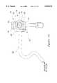
- FIG. 11is an isolated side view of the low profile gastrointestinal feeding system showing the securing device in a post-engagement position according to the present invention
- FIG. 12is an isolated partial bottom view of the low profile gastrointestinal feeding system along line F--F shown in FIG. 11 according to the present invention.
- the low profile gastrointestinal tube feeding system 10comprises a feeding set 14 attached to a low profile gastrostomy tube 16.
- the gastrostomy tube 16includes a tubular member 60 having an external retention member 18 attached at one end and an internal retention member 20 attached at the other end thereof.
- Feeding set 14comprises a hollow elongate tube 86 with a lumen 100 shown in partial fragmentary section formed through tube 86 having a first end (not shown) and a second end 103.
- First end of elongate tube 86is attached to a source of fluid, for example nutritional supplement, to be supplied to the patient through the low profile gastrostomy tube 16, while the second end 103 is attached to a connection member 15.
- the connection member 15has a body 89 that includes opposing side grip portions 106 adapted to be gripped between a user's thumb and forefinger when attaching the connection member 15 to either the elongate tube 86 or the low profile gastronomy tube 16.
- the body 89further includes opposing top and bottom portions 90, 91 and opposing front and back portions 92, 93.
- a horizontal lumen 102forms a passage through one portion of body 89 and merges with vertical lumen 103 that meets lumen 102 at approximately a 90-degree angle at an elbow 110.
- Lumens 102, 103establish a fluid pathway though connection member 15 for the passage of fluid to the low profile gastrostomy tube 16 from the elongate tube 86.
- a tubular-shaped vertical extension member 98extension outwardly from the bottom portion 91 of body 89 along the same downward vertical orientation as lumen 103.
- connection member 15functions as a 90-degree adapter for connecting elongate tube 86 to the external retention member 18 at a low profile in relation to the patient's body.
- a securing device 12according to the present invention is illustrated and provides a means for securing the connection member 15 to the external retention member 18 after attachment of the connection member 15 thereto.
- the securing device 12includes a body 22 that forms a top portion 26, back portion 28 and lower portion 30.
- the top portionhas a flat outer surface 112 and an inner surface 114 which is in opposed relation to the lower portion 30 and includes a locking tab 24 for engaging and securing the securing device 12 to the connection member 15.
- Locking tab 24includes a beveled forward part 44, a flat middle part 46 and a straight back part 47. Beveled forward part 44 forms an angled portion adapted to initially engage and ride over the rear part 93 of connection member 15.
- a retention area 116is provided along inner surface 114 between the back portion 28 and the locking tab 24 of securing device 12 for securely engaging device 12 to connection member 15.
- the back portion 28 of securing device 12forms an aperture 40 adapted to slidably engage the elongate tube 86 therethrough, while the lower portion 30 forms opposing arms 32, 34 having respective distal tips 36, 38 which are adapted to engage the external retention member 18.
- opposing arms 32, 34collectively form a generally curved configuration with arms 32, 34 meeting at an apex 42 located in the middle of back portion 28.
- opposing arms 32, 34can also form a generally straight parallel configuration.
- the external retention member 18includes a body 19 comprising a top surface 33 and a bottom surface 35.
- the bottom surface 35forms opposing legs 58 adapted to be seated against the outer abdominal wall of a patient and to also serve to retain and anchor the external retention member 18 thereto when the low profile gastrostomy tube 16 is inserted into a patient' body.
- the top surface 33includes an axial passageway 79 through body 19 having a distal opening 81 formed at top surface 33 and a proximal opening 83 (FIG. 7) formed at bottom surface 35.
- An annular undercut 74is formed around the circumference of passageway 79 near the distal opening 81 for engaging either an annular flange 66 of cap member 64 for sealing off passageway 79 or retaining flange 94 for attaching the connection member 15 to the external retention member 18 and establishing fluid flow communication between the source of nutrition and the low profile gastrostomy tube 16.
- the engagement of either flange 66 or flange 94 with undercut 74is preferably a snap fit engagement. However, in the alternative an interference fit or a combination of interference and snap fit engagement is felt to fall within the scope of present invention.
- Passageway 79further includes a valve member 48 spaced below undercut 74 and disposed across passageway 79.
- Valve member 48comprises an impermeable barrier having one or more slits 78 which provide an anti-reflux action that prevents fluid from flowing in a direction opposite that of fluid pathway A illustrated in FIGS. 5 and 7.
- Affixed or integrally formed with the external retention member 18is a tethered cap 62 which includes a tether 68 which attaches cap member 64 to external retention member 18.
- Cap member 64has an annular flange 66 adapted to engage undercut 74 when sealing distal opening 81 of passageway 79. Annular undercut 74 is spaced above and concentrically around valve member 48.
- Top surface 33 of external retention member 18also includes a retaining ring 72 which surrounds valve member 48 and provides a protective reinforcing structure around valve member 48 against manual deformation.
- An upper socket 56is integrally formed with or attached to the proximal opening 82 of external retention member 18 at one end and integrally formed with or attached to the tubular member 60 at the other end thereof.
- FIG. 8A bottom view of the external retention member 18 is illustrated in FIG. 8.
- the bottom surface 35 of external retention member 18includes an annular body 65 and two generally opposing grooves 70 which are formed between respective legs 58 and annular body 65.
- Opposing grooves 70have a generally curved configuration adapted to engage and secure respective arms 32, 34 of securing device 12 when device 12 is secured to the external retention member 18 and connection member 15, as shall be discussed in greater detail later.
- a plurality of reinforcing members 76surround annular body 65 and provide structural reinforcement.
- tubular member 60comprises a lumen 59 shown in partial fragmentary section having a distal end 61 and a proximal end 63.
- One end of a lower socket 54is integrally formed with or attached to the proximal end 63 of tubular member 60, while the upper socket 56 is integrally formed with or attached to the distal end 61 of tubular member 60, thereby securing member 60 between the external retention member 18 retained outside the patient and the internal retention member 20 anchored inside the patient.
- Tubular member 60provides a conduit for fluid pathway A for delivery of fluid into the patient's stomach or other viscera.
- the other end of lower socket 54is integrally formed with or attached to the internal retention member 20.
- Internal retention member 20comprises a plurality of flexible retaining arms 50 with each arm 50 including a hinge 51 for flexing the internal retention member 20 into a pre-set enlarged shape illustrated in FIG. 4 that prevents the retention member 20 from being withdrawn through the stoma of a patient.
- the upper part of the retaining arms 50meet at the lower socket 54 at one end and a grommet 50 formed at the other end.
- the grommet 50serves as a fastening support for seating the obturator rod (not shown) during insertion of the low profile gastrostomy tube 16.
- the method for inserting and anchoring the low profile gastrostomy tube 16 using the obturator rodis disclosed in the above referenced U.S. Pat. No. 5,248,302 to Patrick et al.
- FIG. 5an isolated side view of the low profile gastrostomy tube 16 is shown with the tubular member 60 inserted through a stoma 88 and into the stomach 84 or other viscera of a patient by via passage 55 formed through the abdominal wall 80 and stomach wall 82 of a patient.
- the internal retention member 20 attached to the tubular member 60is shown in its pre-set enlarged position which anchors retaining arms 50 against the stomach lining 82 and prevents withdrawal thereof through passage 55.
- the external retention member 18 attached to the distal end 61 of tubular member 60prevents tubular member 60 from inadvertently slipping into passage 55.
- FIGS. 7-12The method for engaging the securing device 12 to both the connection member 15 and the external retention member 18 once the low profile gastrostomy tube 16 has been properly inserted into a patient is illustrated in the sequence of positions shown in FIGS. 7-12.
- the pre-engagement position of the securing device 12is shown as device 12 is slidably engaged along elongate tube 86 toward connection member which is attached to external retention member 18.
- arms 32, 34 of securing device 12are generally aligned with respective grooves 70 of external retention member 18.
- the locking tab 24 of securing device 12is also aligned with the top portion 90 of connection member 15.
- each of tips 36, 38engage respective grooves 70 of the external retention member 18, while the beveled forward part 44 of locking tab 24 concurrently engages the top portion 90 of connection member 15.
- tips 36 and 38have sufficiently entered into grooves 70 so that arms 32, 34 begin to flex as arms 32, 34 follow the slightly curved path formed by respective grooves 70.
- the top portion 90 of connection member 15rides under the beveled forward part 44 of locking tab 24 until portion 90 rides under flat middle part 46.
- arms 32, 34In the post engagement position of securing device 12 shown in FIGS. 11 and 12, arms 32, 34 have fully engaged grooves 70. While arms 32, 34 become fully engaged in grooves 70, the front portion 90 of connection member 15 passes under the flat middle part 46, until front portion 90 falls behind part 46 and becomes recessed in retention area 116 formed between straight back part 47 and back portion 28 of securing device 12, thereby securely engaging the top portion 90 of device 12 to connection member 15. In the post engagement position, arms 32, 34 have become fully engaged within respective grooves 70 of external retention member 18 and the top portion 90 of connection member 15 is full recessed within retention area 116, thereby fully securing connection member 15 to external retention member 18 to the top and bottom portions 26, 30 of securing device 12. Neither the external retention member 18 nor the connection member 15 may be disengaged from one another without first physically disengaging the securing device 12 from either or both members 15 or 18.
- the securing device 12is injection molded from polypropylene or other suitable medical-grade plastic that possesses sufficient flexibility and durability.
- polypropylene or other suitable medical-grade plasticthat possesses sufficient flexibility and durability.
- stainless steel or other metal suitable for medical useis also felt to fall within the scope of the present invention.
Landscapes
- Health & Medical Sciences (AREA)
- Life Sciences & Earth Sciences (AREA)
- Veterinary Medicine (AREA)
- Animal Behavior & Ethology (AREA)
- General Health & Medical Sciences (AREA)
- Public Health (AREA)
- Pulmonology (AREA)
- Biophysics (AREA)
- Engineering & Computer Science (AREA)
- Anesthesiology (AREA)
- Biomedical Technology (AREA)
- Heart & Thoracic Surgery (AREA)
- Hematology (AREA)
- Gastroenterology & Hepatology (AREA)
- Medical Preparation Storing Or Oral Administration Devices (AREA)
- Infusion, Injection, And Reservoir Apparatuses (AREA)
- Media Introduction/Drainage Providing Device (AREA)
- Materials For Medical Uses (AREA)
- Rigid Pipes And Flexible Pipes (AREA)
Abstract
Description
Claims (16)
Priority Applications (12)
| Application Number | Priority Date | Filing Date | Title |
|---|---|---|---|
| US09/257,164US6045536A (en) | 1999-02-24 | 1999-02-24 | Securing device for a low profile gastrostomy tube |
| IL14502300AIL145023A0 (en) | 1999-02-24 | 2000-02-24 | Securing device for a low profile gastrostomy tube |
| EP00914726.5AEP1161273B1 (en) | 1999-02-24 | 2000-02-24 | Securing device for a low profile gastrostomy tube |
| PCT/US2000/004976WO2000050110A1 (en) | 1999-02-24 | 2000-02-24 | Securing device for a low profile gastrostomy tube |
| TR2001/02495TTR200102495T2 (en) | 1999-02-24 | 2000-02-24 | Safety device for low profile gastrostomy tube. |
| CA002355597ACA2355597C (en) | 1999-02-24 | 2000-02-24 | Securing device for a low profile gastrostomy tube |
| JP2000600720AJP3585847B2 (en) | 1999-02-24 | 2000-02-24 | Apparatus for penetrating the wall of an organ and method of fixing connecting member attached to hollow external holding member |
| AU36077/00AAU766117C (en) | 1999-02-24 | 2000-02-24 | Securing device for a low profile gastrostomy tube |
| PL350674APL197743B1 (en) | 1999-02-24 | 2000-02-24 | Securing device for a low profile gastrostomy tube |
| NO20014056ANO20014056L (en) | 1999-02-24 | 2001-08-21 | Device for securing a low profile gastrostomy tube |
| IL145023AIL145023A (en) | 1999-02-24 | 2001-08-21 | Securing device for a low profile gastrostomy tube |
| US10/170,821US7070587B2 (en) | 1999-02-24 | 2002-06-13 | Securing device for a low profile gastrostomy tube having an inflatable balloon |
Applications Claiming Priority (1)
| Application Number | Priority Date | Filing Date | Title |
|---|---|---|---|
| US09/257,164US6045536A (en) | 1999-02-24 | 1999-02-24 | Securing device for a low profile gastrostomy tube |
Related Child Applications (1)
| Application Number | Title | Priority Date | Filing Date |
|---|---|---|---|
| US50340000AContinuation-In-Part | 1999-02-24 | 2000-02-14 |
Publications (1)
| Publication Number | Publication Date |
|---|---|
| US6045536Atrue US6045536A (en) | 2000-04-04 |
Family
ID=22975158
Family Applications (1)
| Application Number | Title | Priority Date | Filing Date |
|---|---|---|---|
| US09/257,164Expired - LifetimeUS6045536A (en) | 1999-02-24 | 1999-02-24 | Securing device for a low profile gastrostomy tube |
Country Status (10)
| Country | Link |
|---|---|
| US (1) | US6045536A (en) |
| EP (1) | EP1161273B1 (en) |
| JP (1) | JP3585847B2 (en) |
| AU (1) | AU766117C (en) |
| CA (1) | CA2355597C (en) |
| IL (2) | IL145023A0 (en) |
| NO (1) | NO20014056L (en) |
| PL (1) | PL197743B1 (en) |
| TR (1) | TR200102495T2 (en) |
| WO (1) | WO2000050110A1 (en) |
Cited By (46)
| Publication number | Priority date | Publication date | Assignee | Title |
|---|---|---|---|---|
| US6355028B2 (en) | 2000-10-11 | 2002-03-12 | Popcab,Llc | Stable port device for port off-pump beating heart coronary artery bypass surgery system |
| US20020077604A1 (en)* | 2000-12-19 | 2002-06-20 | Kimberly-Clark Worldwide, Inc. | Sealing valve assembly for medical products |
| US6464691B1 (en) | 2000-10-11 | 2002-10-15 | Popcab, Llc | Port device for port off-pump beating heart coronary artery bypass surgery system |
| US6464690B1 (en) | 2000-10-11 | 2002-10-15 | Popcab, Llc | Port off-pump beating heart coronary artery bypass heart stabilization system |
| US20020177806A1 (en)* | 1999-02-24 | 2002-11-28 | Meier Kevin C. | Securing device for a low profile gastrostomy tube having an inflatable balloon |
| US6503245B2 (en) | 2000-10-11 | 2003-01-07 | Medcanica, Inc. | Method of performing port off-pump beating heart coronary artery bypass surgery |
| US6582420B2 (en) | 2000-10-11 | 2003-06-24 | Popcab, Llc | Intercostal lockable directable port device |
| US6592573B2 (en) | 2000-10-11 | 2003-07-15 | Popcab, Llc | Through-port heart stabilization system |
| US20040024363A1 (en)* | 2002-04-22 | 2004-02-05 | Goldberg Elizabeth A. | Low profile combination device for gastrostomy or jejunostomy applications having anti-granuloma formation characteristics |
| US6767340B2 (en) | 2000-12-19 | 2004-07-27 | Kimberly-Clark Worldwide, Inc. | Sealing valve assembly for medical products |
| US20050033268A1 (en)* | 2003-08-06 | 2005-02-10 | Kimberly-Clark Worldwide, Inc. | Connector with protrusion adapted for interconnection with second member |
| US20050033240A1 (en)* | 2001-10-03 | 2005-02-10 | Hideto Oishi | Esophagus stoma button |
| US20050033269A1 (en)* | 2003-08-06 | 2005-02-10 | Kimberly-Clark Worldwide, Inc. | Ferrule and enteral tube incorporating a ferrule |
| US20050187524A1 (en)* | 2000-12-19 | 2005-08-25 | Willis Allan F. | Sealing valve assembly for medical products |
| GB2424584A (en)* | 2005-03-30 | 2006-10-04 | Deborah Calvert | Stoma device for maintaining a gastrostomy and/or urostomy stoma |
| US20070168014A1 (en)* | 2006-01-13 | 2007-07-19 | Jimenez Teodoro S | Stent Delivery System |
| USD561329S1 (en)* | 2006-10-04 | 2008-02-05 | Kimberly-Clark Worldwide, Inc. | Low profile transpyloric jejunostomy catheter |
| US20090112183A1 (en)* | 2004-05-14 | 2009-04-30 | C. R. Bard, Inc. | Medical devices and methods of use |
| US20090157053A1 (en)* | 2006-11-30 | 2009-06-18 | Davis Phillip J | System and method for implanting a catheter |
| US20090163892A1 (en)* | 2007-12-19 | 2009-06-25 | Kimberly-Clark Worldwide, Inc. | Automatic Shut-Off Connector for Enteral Feeding Devices |
| US20090287157A1 (en)* | 2008-05-14 | 2009-11-19 | Tyco Healthcare Group Lp | Fistula catheter and fistula catheter set |
| EP2168559A1 (en) | 2008-09-30 | 2010-03-31 | Tyco Healthcare Group LP | Skin Level Device for use with Gastronomy Tube |
| US20100094399A1 (en)* | 2001-04-30 | 2010-04-15 | C. R. Bard, Inc. | Variable speed self-expanding stent delivery system and luer locking connector |
| US20100168756A1 (en)* | 2006-08-07 | 2010-07-01 | Dorn Juergen | Hand-held actuator device |
| US20100174290A1 (en)* | 2007-07-11 | 2010-07-08 | C.R. Bard, Inc. | Device for catheter sheath retraction |
| US20100312192A1 (en)* | 2009-06-04 | 2010-12-09 | Alan Fitzgerald | Gastrostomy feeding apparatus and method |
| US7935141B2 (en) | 2005-08-17 | 2011-05-03 | C. R. Bard, Inc. | Variable speed stent delivery system |
| US7967788B2 (en) | 2007-05-25 | 2011-06-28 | Iq Medical Devices, Llc | Catheter with variable attachment means |
| US20110196341A1 (en)* | 2010-02-09 | 2011-08-11 | C. R. Bard, Inc. | Deflation indicator for a medical device bolster |
| US8551043B2 (en) | 2006-04-21 | 2013-10-08 | C. R. Bard, Inc. | Feeding device and bolster apparatus and method for making the same |
| US8715244B2 (en) | 2009-07-07 | 2014-05-06 | C. R. Bard, Inc. | Extensible internal bolster for a medical device |
| US20140207071A1 (en)* | 2005-09-16 | 2014-07-24 | Applied Medical Technology, Inc. | Non-Balloon Low Profile Feed Device With Insertion/Removal Tool |
| US8834370B2 (en) | 2011-12-15 | 2014-09-16 | Cook Medical Technologies Llc | Ultrasonic percutaneous enteral feeding tube |
| US8858533B2 (en) | 2004-06-29 | 2014-10-14 | C. R. Bard, Inc. | Methods and systems for providing fluid communication with a gastrostomy tube |
| WO2014203259A1 (en) | 2013-06-20 | 2014-12-24 | Hadasit Medical Research Services And Development Ltd. | Devices and methods for percutaneous endoscopic gastrostomy and other ostomy procedures |
| CN106163487A (en)* | 2014-04-02 | 2016-11-23 | 费森尤斯卡比德国有限公司 | Gastrostomy tube including cap assembly |
| AU2014200323B2 (en)* | 2006-11-30 | 2017-04-27 | Ingenion Medical Limited | System and method for implanting a catheter |
| RU2619210C2 (en)* | 2011-12-22 | 2017-05-12 | Кимберли-Кларк Ворлдвайд, Инк. | Improved base for enteral nutrition device |
| US9801745B2 (en) | 2010-10-21 | 2017-10-31 | C.R. Bard, Inc. | System to deliver a bodily implant |
| US10426708B2 (en) | 2014-12-23 | 2019-10-01 | Fidmi Medical Ltd. | Devices and methods for percutaneous endoscopic gastronomy and other ostomy procedures |
| US10702304B2 (en) | 2014-12-23 | 2020-07-07 | Fidmi Medical Ltd. | Devices and methods for ports to living tissue and/or lumens and related procedures |
| US11026822B2 (en) | 2006-01-13 | 2021-06-08 | C. R. Bard, Inc. | Stent delivery system |
| US11219752B2 (en) | 2016-07-29 | 2022-01-11 | Avent, Inc. | Tamper proof connector for enteral feeding devices |
| US11229580B1 (en) | 2020-12-04 | 2022-01-25 | Meredith I. Sharp | Securing a percutaneous feeding device |
| US11759402B2 (en) | 2018-06-29 | 2023-09-19 | Generica Medical International, Inc. | Enteral feeding systems and methods |
| US11793544B2 (en) | 2016-06-29 | 2023-10-24 | Fidmi Medical Ltd. | Measuring device |
Families Citing this family (9)
| Publication number | Priority date | Publication date | Assignee | Title |
|---|---|---|---|---|
| WO2002066108A1 (en)* | 2001-02-15 | 2002-08-29 | Sherwood Services, Ag | Securing device for a low profile gastrostomy tube |
| US7549200B2 (en) | 2005-05-27 | 2009-06-23 | Kimberly-Clark Worldwide, Inc. | Clamp for flexible tube |
| US7582098B2 (en) | 2006-08-28 | 2009-09-01 | Kimberly-Clark Wolrdwide, Inc. | Percutaneous gastrointestinal anchoring kit |
| US8795236B2 (en)* | 2011-09-28 | 2014-08-05 | Kimberly-Clark Worldwide, Inc. | One step cecostomy |
| USD679393S1 (en) | 2011-12-22 | 2013-04-02 | Kimberly-Clark Worldwide, Inc. | Enteral feeding tube base |
| CN106821765B (en)* | 2017-03-08 | 2023-11-03 | 杭州富善医疗器械有限公司 | Gastrostomy tube and fixing pad for gastrostomy tube |
| WO2020019090A1 (en)* | 2018-07-24 | 2020-01-30 | Pontificia Universidad Catolica De Chile | Simplified device for mounting a percutaneous endoscopic gastrotomy (peg) tube, which is installed outside the abdominal wall of a patient and which facilitates the connection thereof with an enteral feeding tube |
| JP7249869B2 (en)* | 2019-05-20 | 2023-03-31 | 住友ベークライト株式会社 | Connectors, tubing sets and gastrostomy catheter sets |
| GB201907070D0 (en) | 2019-05-20 | 2019-07-03 | Metis Design Bv | Connector for a gastrostomy device |
Citations (11)
| Publication number | Priority date | Publication date | Assignee | Title |
|---|---|---|---|---|
| US3261357A (en)* | 1963-08-26 | 1966-07-19 | Baxter Don Inc | Extractor for peritoneal entry device |
| US3794041A (en)* | 1971-11-30 | 1974-02-26 | Yeda Res & Dev | Gastrointestinal catheter |
| US3814080A (en)* | 1972-11-13 | 1974-06-04 | Becton Dickinson Co | Vessel cannulator and clamp for lymphangiography |
| US4944732A (en)* | 1988-08-15 | 1990-07-31 | Sandoz Nutrition Corporation | Gastrostomy feeding port |
| US5007914A (en)* | 1988-06-20 | 1991-04-16 | Schweigerling Paul E | Catheter-insertion device |
| US5183464A (en)* | 1991-05-17 | 1993-02-02 | Interventional Thermodynamics, Inc. | Radially expandable dilator |
| US5234425A (en)* | 1989-03-03 | 1993-08-10 | Thomas J. Fogarty | Variable diameter sheath method and apparatus for use in body passages |
| US5248302A (en)* | 1992-08-05 | 1993-09-28 | Biosearch Medical Products Inc. | Percutaneous obturatable internal anchoring device |
| US5267983A (en)* | 1992-04-22 | 1993-12-07 | Clintec Nutrition Co. | Enteral adapter and tip protector |
| US5407430A (en)* | 1994-03-21 | 1995-04-18 | Peters; Michael J. | Intravenous catheter |
| US5456699A (en)* | 1993-12-08 | 1995-10-10 | Intermedics, Inc. | Cardiac stimulator lead insertion tool |
Family Cites Families (10)
| Publication number | Priority date | Publication date | Assignee | Title |
|---|---|---|---|---|
| US4233974A (en)* | 1978-09-05 | 1980-11-18 | Baxter Travenol Laboratories, Inc. | Spinal needle assembly |
| DE2949865C2 (en)* | 1979-12-12 | 1985-04-18 | B. Braun Melsungen Ag, 3508 Melsungen | Hose connection for medical devices |
| US5073166A (en)* | 1989-02-15 | 1991-12-17 | Medical Innovations Corporation | Method and apparatus for emplacement of a gastrostomy catheter |
| US5192273A (en)* | 1989-07-24 | 1993-03-09 | Steven F. Bierman | Catheterization system |
| DE69228257T2 (en)* | 1991-11-06 | 1999-07-08 | Inbae M.D. Phoenix Yoon, Md. | HOLDER FOR SURGICAL INSTRUMENTS |
| US5484420A (en)* | 1992-07-09 | 1996-01-16 | Wilson-Cook Medical Inc. | Retention bolsters for percutaneous catheters |
| US5549657A (en)* | 1994-05-12 | 1996-08-27 | C.R. Bard, Inc. | Low profile adaptor for gastrostomy feeding tube |
| US5766220A (en)* | 1996-02-29 | 1998-06-16 | Moenning; Stephen P. | Apparatus and method for protecting a port site opening in the wall of a body cavity |
| JPH105342A (en)* | 1996-06-27 | 1998-01-13 | A S A Sangyo Kk | Transperitoneal administration catheter and administration container set |
| US5776111A (en)* | 1996-11-07 | 1998-07-07 | Medical Components, Inc. | Multiple catheter assembly |
- 1999
- 1999-02-24USUS09/257,164patent/US6045536A/ennot_activeExpired - Lifetime
- 2000
- 2000-02-24ILIL14502300Apatent/IL145023A0/enactiveIP Right Grant
- 2000-02-24PLPL350674Apatent/PL197743B1/enunknown
- 2000-02-24EPEP00914726.5Apatent/EP1161273B1/ennot_activeExpired - Lifetime
- 2000-02-24CACA002355597Apatent/CA2355597C/ennot_activeExpired - Lifetime
- 2000-02-24AUAU36077/00Apatent/AU766117C/ennot_activeExpired
- 2000-02-24TRTR2001/02495Tpatent/TR200102495T2/enunknown
- 2000-02-24JPJP2000600720Apatent/JP3585847B2/ennot_activeExpired - Lifetime
- 2000-02-24WOPCT/US2000/004976patent/WO2000050110A1/enactiveIP Right Grant
- 2001
- 2001-08-21NONO20014056Apatent/NO20014056L/ennot_activeApplication Discontinuation
- 2001-08-21ILIL145023Apatent/IL145023A/ennot_activeIP Right Cessation
Patent Citations (11)
| Publication number | Priority date | Publication date | Assignee | Title |
|---|---|---|---|---|
| US3261357A (en)* | 1963-08-26 | 1966-07-19 | Baxter Don Inc | Extractor for peritoneal entry device |
| US3794041A (en)* | 1971-11-30 | 1974-02-26 | Yeda Res & Dev | Gastrointestinal catheter |
| US3814080A (en)* | 1972-11-13 | 1974-06-04 | Becton Dickinson Co | Vessel cannulator and clamp for lymphangiography |
| US5007914A (en)* | 1988-06-20 | 1991-04-16 | Schweigerling Paul E | Catheter-insertion device |
| US4944732A (en)* | 1988-08-15 | 1990-07-31 | Sandoz Nutrition Corporation | Gastrostomy feeding port |
| US5234425A (en)* | 1989-03-03 | 1993-08-10 | Thomas J. Fogarty | Variable diameter sheath method and apparatus for use in body passages |
| US5183464A (en)* | 1991-05-17 | 1993-02-02 | Interventional Thermodynamics, Inc. | Radially expandable dilator |
| US5267983A (en)* | 1992-04-22 | 1993-12-07 | Clintec Nutrition Co. | Enteral adapter and tip protector |
| US5248302A (en)* | 1992-08-05 | 1993-09-28 | Biosearch Medical Products Inc. | Percutaneous obturatable internal anchoring device |
| US5456699A (en)* | 1993-12-08 | 1995-10-10 | Intermedics, Inc. | Cardiac stimulator lead insertion tool |
| US5407430A (en)* | 1994-03-21 | 1995-04-18 | Peters; Michael J. | Intravenous catheter |
Cited By (76)
| Publication number | Priority date | Publication date | Assignee | Title |
|---|---|---|---|---|
| US20020177806A1 (en)* | 1999-02-24 | 2002-11-28 | Meier Kevin C. | Securing device for a low profile gastrostomy tube having an inflatable balloon |
| US7070587B2 (en)* | 1999-02-24 | 2006-07-04 | Sherwood Services Ag | Securing device for a low profile gastrostomy tube having an inflatable balloon |
| US6582420B2 (en) | 2000-10-11 | 2003-06-24 | Popcab, Llc | Intercostal lockable directable port device |
| US6464690B1 (en) | 2000-10-11 | 2002-10-15 | Popcab, Llc | Port off-pump beating heart coronary artery bypass heart stabilization system |
| US6464691B1 (en) | 2000-10-11 | 2002-10-15 | Popcab, Llc | Port device for port off-pump beating heart coronary artery bypass surgery system |
| US6503245B2 (en) | 2000-10-11 | 2003-01-07 | Medcanica, Inc. | Method of performing port off-pump beating heart coronary artery bypass surgery |
| US6592573B2 (en) | 2000-10-11 | 2003-07-15 | Popcab, Llc | Through-port heart stabilization system |
| US6355028B2 (en) | 2000-10-11 | 2002-03-12 | Popcab,Llc | Stable port device for port off-pump beating heart coronary artery bypass surgery system |
| US20050187524A1 (en)* | 2000-12-19 | 2005-08-25 | Willis Allan F. | Sealing valve assembly for medical products |
| US20020077604A1 (en)* | 2000-12-19 | 2002-06-20 | Kimberly-Clark Worldwide, Inc. | Sealing valve assembly for medical products |
| US6767340B2 (en) | 2000-12-19 | 2004-07-27 | Kimberly-Clark Worldwide, Inc. | Sealing valve assembly for medical products |
| US8579870B2 (en) | 2000-12-19 | 2013-11-12 | Kimberly-Clark Worldwide, Inc. | Sealing valve assembly for medical products |
| US20070255257A1 (en)* | 2000-12-19 | 2007-11-01 | Kimberly-Clark Worldwide | Sealing Valve Assembly for Medical Products |
| US6908449B2 (en) | 2000-12-19 | 2005-06-21 | Kimberly-Clark Worldwide, Inc. | Sealing valve assembly for medical products |
| US8062344B2 (en) | 2001-04-30 | 2011-11-22 | Angiomed Gmbh & Co. Medizintechnik Kg | Variable speed self-expanding stent delivery system and luer locking connector |
| US20100094399A1 (en)* | 2001-04-30 | 2010-04-15 | C. R. Bard, Inc. | Variable speed self-expanding stent delivery system and luer locking connector |
| US7678082B2 (en)* | 2001-10-03 | 2010-03-16 | Sumitomo Bakelite Co., Ltd. | Esophagus stoma button |
| US20050033240A1 (en)* | 2001-10-03 | 2005-02-10 | Hideto Oishi | Esophagus stoma button |
| US20040024363A1 (en)* | 2002-04-22 | 2004-02-05 | Goldberg Elizabeth A. | Low profile combination device for gastrostomy or jejunostomy applications having anti-granuloma formation characteristics |
| US6997909B2 (en) | 2002-04-22 | 2006-02-14 | The Children's Hospital Of Philadelphia | Low profile combination device for gastrostomy or jejunostomy applications having anti-granuloma formation characteristics |
| US20060078575A1 (en)* | 2002-04-22 | 2006-04-13 | Goldberg Elizabeth A | Low profile combination device for gastrostomy or jejunostomy applications having anti-granuloma formation characteristics |
| US20050033269A1 (en)* | 2003-08-06 | 2005-02-10 | Kimberly-Clark Worldwide, Inc. | Ferrule and enteral tube incorporating a ferrule |
| US20050033268A1 (en)* | 2003-08-06 | 2005-02-10 | Kimberly-Clark Worldwide, Inc. | Connector with protrusion adapted for interconnection with second member |
| US20090112183A1 (en)* | 2004-05-14 | 2009-04-30 | C. R. Bard, Inc. | Medical devices and methods of use |
| US8858533B2 (en) | 2004-06-29 | 2014-10-14 | C. R. Bard, Inc. | Methods and systems for providing fluid communication with a gastrostomy tube |
| US9682224B2 (en) | 2004-06-29 | 2017-06-20 | C. R. Bard, Inc. | Method and systems for providing fluid communication with a gastrostomy tube |
| GB2424584A (en)* | 2005-03-30 | 2006-10-04 | Deborah Calvert | Stoma device for maintaining a gastrostomy and/or urostomy stoma |
| US20060224131A1 (en)* | 2005-03-30 | 2006-10-05 | Deborah Calvert | Stoma devices and dressings and methods therefor |
| US7935141B2 (en) | 2005-08-17 | 2011-05-03 | C. R. Bard, Inc. | Variable speed stent delivery system |
| US20140207071A1 (en)* | 2005-09-16 | 2014-07-24 | Applied Medical Technology, Inc. | Non-Balloon Low Profile Feed Device With Insertion/Removal Tool |
| US9675486B2 (en) | 2006-01-13 | 2017-06-13 | C.R. Bard, Inc. | Stent delivery system |
| US11026822B2 (en) | 2006-01-13 | 2021-06-08 | C. R. Bard, Inc. | Stent delivery system |
| US8808346B2 (en) | 2006-01-13 | 2014-08-19 | C. R. Bard, Inc. | Stent delivery system |
| US20070168014A1 (en)* | 2006-01-13 | 2007-07-19 | Jimenez Teodoro S | Stent Delivery System |
| US8551043B2 (en) | 2006-04-21 | 2013-10-08 | C. R. Bard, Inc. | Feeding device and bolster apparatus and method for making the same |
| US20100168756A1 (en)* | 2006-08-07 | 2010-07-01 | Dorn Juergen | Hand-held actuator device |
| US9078779B2 (en) | 2006-08-07 | 2015-07-14 | C. R. Bard, Inc. | Hand-held actuator device |
| US10993822B2 (en) | 2006-08-07 | 2021-05-04 | C. R. Bard, Inc. | Hand-held actuator device |
| USD561329S1 (en)* | 2006-10-04 | 2008-02-05 | Kimberly-Clark Worldwide, Inc. | Low profile transpyloric jejunostomy catheter |
| US9452278B2 (en) | 2006-11-30 | 2016-09-27 | Ingenion Medical Limited | System and method for implanting a catheter |
| AU2014200323B2 (en)* | 2006-11-30 | 2017-04-27 | Ingenion Medical Limited | System and method for implanting a catheter |
| US9011314B2 (en)* | 2006-11-30 | 2015-04-21 | Ingenion Medical Limited | System and method for implanting a catheter |
| US20090157053A1 (en)* | 2006-11-30 | 2009-06-18 | Davis Phillip J | System and method for implanting a catheter |
| US7967788B2 (en) | 2007-05-25 | 2011-06-28 | Iq Medical Devices, Llc | Catheter with variable attachment means |
| US9662474B2 (en) | 2007-05-25 | 2017-05-30 | Iq Medical Devices, Llc | Catheter with variable attachment means |
| US8500789B2 (en) | 2007-07-11 | 2013-08-06 | C. R. Bard, Inc. | Device for catheter sheath retraction |
| US11026821B2 (en) | 2007-07-11 | 2021-06-08 | C. R. Bard, Inc. | Device for catheter sheath retraction |
| US9421115B2 (en) | 2007-07-11 | 2016-08-23 | C. R. Bard, Inc. | Device for catheter sheath retraction |
| US20100174290A1 (en)* | 2007-07-11 | 2010-07-08 | C.R. Bard, Inc. | Device for catheter sheath retraction |
| US10206800B2 (en) | 2007-07-11 | 2019-02-19 | C.R. Bard, Inc. | Device for catheter sheath retraction |
| US8142418B2 (en) | 2007-12-19 | 2012-03-27 | Kimberly-Clark Worldwide, Inc. | Automatic shut-off connector for enteral feeding devices |
| US20090163892A1 (en)* | 2007-12-19 | 2009-06-25 | Kimberly-Clark Worldwide, Inc. | Automatic Shut-Off Connector for Enteral Feeding Devices |
| US20090287157A1 (en)* | 2008-05-14 | 2009-11-19 | Tyco Healthcare Group Lp | Fistula catheter and fistula catheter set |
| US20100081991A1 (en)* | 2008-09-30 | 2010-04-01 | Tyco Healthcare Group Lp | Skin level device for use with gastrostomy tube |
| EP2168559A1 (en) | 2008-09-30 | 2010-03-31 | Tyco Healthcare Group LP | Skin Level Device for use with Gastronomy Tube |
| US20100312192A1 (en)* | 2009-06-04 | 2010-12-09 | Alan Fitzgerald | Gastrostomy feeding apparatus and method |
| US8951232B2 (en) | 2009-06-04 | 2015-02-10 | Covidien Lp | Gastrostomy feeding apparatus and method |
| US8715244B2 (en) | 2009-07-07 | 2014-05-06 | C. R. Bard, Inc. | Extensible internal bolster for a medical device |
| US9572751B2 (en) | 2009-07-07 | 2017-02-21 | C. R. Bard, Inc. | Extensible internal bolster for a medical device |
| US20110196341A1 (en)* | 2010-02-09 | 2011-08-11 | C. R. Bard, Inc. | Deflation indicator for a medical device bolster |
| US10952879B2 (en) | 2010-10-21 | 2021-03-23 | C. R. Bard, Inc. | System to deliver a bodily implant |
| US9801745B2 (en) | 2010-10-21 | 2017-10-31 | C.R. Bard, Inc. | System to deliver a bodily implant |
| US8834370B2 (en) | 2011-12-15 | 2014-09-16 | Cook Medical Technologies Llc | Ultrasonic percutaneous enteral feeding tube |
| RU2619210C2 (en)* | 2011-12-22 | 2017-05-12 | Кимберли-Кларк Ворлдвайд, Инк. | Improved base for enteral nutrition device |
| WO2014203259A1 (en) | 2013-06-20 | 2014-12-24 | Hadasit Medical Research Services And Development Ltd. | Devices and methods for percutaneous endoscopic gastrostomy and other ostomy procedures |
| US10695270B2 (en) | 2013-06-20 | 2020-06-30 | Hadasit Medical Research Services And Development Ltd. | Devices and methods for percutaneous endoscopic gastrostomy and other ostomy procedures |
| EP3010471A4 (en)* | 2013-06-20 | 2017-03-08 | Hadasit Medical Research Services and Development Ltd. | Devices and methods for percutaneous endoscopic gastrostomy and other ostomy procedures |
| CN106163487A (en)* | 2014-04-02 | 2016-11-23 | 费森尤斯卡比德国有限公司 | Gastrostomy tube including cap assembly |
| US20170112721A1 (en)* | 2014-04-02 | 2017-04-27 | Fresenius Kabi Deutschland Gmbh | Gastrostomy tube comprising a cap assembly |
| US10702304B2 (en) | 2014-12-23 | 2020-07-07 | Fidmi Medical Ltd. | Devices and methods for ports to living tissue and/or lumens and related procedures |
| US10426708B2 (en) | 2014-12-23 | 2019-10-01 | Fidmi Medical Ltd. | Devices and methods for percutaneous endoscopic gastronomy and other ostomy procedures |
| US11638594B2 (en) | 2014-12-23 | 2023-05-02 | Fidmi Medical Ltd. | Replaceable inner tube |
| US11793544B2 (en) | 2016-06-29 | 2023-10-24 | Fidmi Medical Ltd. | Measuring device |
| US11219752B2 (en) | 2016-07-29 | 2022-01-11 | Avent, Inc. | Tamper proof connector for enteral feeding devices |
| US11759402B2 (en) | 2018-06-29 | 2023-09-19 | Generica Medical International, Inc. | Enteral feeding systems and methods |
| US11229580B1 (en) | 2020-12-04 | 2022-01-25 | Meredith I. Sharp | Securing a percutaneous feeding device |
Also Published As
| Publication number | Publication date |
|---|---|
| WO2000050110A1 (en) | 2000-08-31 |
| AU3607700A (en) | 2000-09-14 |
| AU766117C (en) | 2005-04-07 |
| EP1161273A1 (en) | 2001-12-12 |
| IL145023A0 (en) | 2002-06-30 |
| IL145023A (en) | 2006-10-05 |
| EP1161273B1 (en) | 2015-04-08 |
| NO20014056L (en) | 2001-10-16 |
| CA2355597C (en) | 2009-07-07 |
| AU766117B2 (en) | 2003-10-09 |
| NO20014056D0 (en) | 2001-08-21 |
| PL350674A1 (en) | 2003-01-27 |
| JP2002537076A (en) | 2002-11-05 |
| JP3585847B2 (en) | 2004-11-04 |
| PL197743B1 (en) | 2008-04-30 |
| EP1161273A4 (en) | 2005-08-17 |
| CA2355597A1 (en) | 2000-08-31 |
| TR200102495T2 (en) | 2002-01-21 |
Similar Documents
| Publication | Publication Date | Title |
|---|---|---|
| US6045536A (en) | Securing device for a low profile gastrostomy tube | |
| US7070587B2 (en) | Securing device for a low profile gastrostomy tube having an inflatable balloon | |
| US6802836B2 (en) | Low profile adaptor for use with a medical catheter | |
| US5549657A (en) | Low profile adaptor for gastrostomy feeding tube | |
| US8221389B2 (en) | Low profile adaptor for use with a medical catheter | |
| US6979322B2 (en) | Low profile adaptor for use with a medical catheter | |
| WO2002066108A1 (en) | Securing device for a low profile gastrostomy tube | |
| US7628775B2 (en) | Safety Y-port adaptor and medical catheter assembly including the same | |
| US20230000725A1 (en) | Connector for a Gastrostomy Device |
Legal Events
| Date | Code | Title | Description |
|---|---|---|---|
| AS | Assignment | Owner name:SHERWOOD SERVICES A.G., SWITZERLAND Free format text:ASSIGNMENT OF ASSIGNORS INTEREST;ASSIGNOR:VON DYCK, PETER;REEL/FRAME:010023/0697 Effective date:19990521 Owner name:SHERWOOD SERVICES A.G., SWITZERLAND Free format text:ASSIGNMENT OF ASSIGNORS INTEREST;ASSIGNORS:MEIER, KEVIN C.;BODICKY, RAYMOND O.;FOURNIE, GLENN;AND OTHERS;REEL/FRAME:010022/0774;SIGNING DATES FROM 19990428 TO 19990503 | |
| STCF | Information on status: patent grant | Free format text:PATENTED CASE | |
| REMI | Maintenance fee reminder mailed | ||
| FEPP | Fee payment procedure | Free format text:PAYOR NUMBER ASSIGNED (ORIGINAL EVENT CODE: ASPN); ENTITY STATUS OF PATENT OWNER: LARGE ENTITY | |
| REIN | Reinstatement after maintenance fee payment confirmed | ||
| FP | Lapsed due to failure to pay maintenance fee | Effective date:20040404 | |
| FEPP | Fee payment procedure | Free format text:PETITION RELATED TO MAINTENANCE FEES GRANTED (ORIGINAL EVENT CODE: PMFG); ENTITY STATUS OF PATENT OWNER: LARGE ENTITY | |
| FEPP | Fee payment procedure | Free format text:PETITION RELATED TO MAINTENANCE FEES FILED (ORIGINAL EVENT CODE: PMFP); ENTITY STATUS OF PATENT OWNER: LARGE ENTITY | |
| FPAY | Fee payment | Year of fee payment:4 | |
| SULP | Surcharge for late payment | ||
| PRDP | Patent reinstated due to the acceptance of a late maintenance fee | Effective date:20051003 | |
| FPAY | Fee payment | Year of fee payment:8 | |
| AS | Assignment | Owner name:COVIDIEN AG, SWITZERLAND Free format text:CHANGE OF NAME;ASSIGNOR:SHERWOOD SERVICES AG;REEL/FRAME:021371/0142 Effective date:20070309 | |
| FPAY | Fee payment | Year of fee payment:12 | |
| AS | Assignment | Owner name:CARDINAL HEALTH IRELAND UNLIMITED COMPANY, IRELAND Free format text:ASSIGNMENT OF ASSIGNORS INTEREST;ASSIGNORS:COVIDIEN AG;COVIDIEN FINANCE INTERNATIONAL GMBH;REEL/FRAME:044763/0234 Effective date:20170729 |