US6045433A - Apparatus for optical inspection of wafers during polishing - Google Patents
Apparatus for optical inspection of wafers during polishingDownload PDFInfo
- Publication number
- US6045433A US6045433AUS08/497,382US49738295AUS6045433AUS 6045433 AUS6045433 AUS 6045433AUS 49738295 AUS49738295 AUS 49738295AUS 6045433 AUS6045433 AUS 6045433A
- Authority
- US
- United States
- Prior art keywords
- wafer
- water
- measuring
- window
- thickness
- Prior art date
- Legal status (The legal status is an assumption and is not a legal conclusion. Google has not performed a legal analysis and makes no representation as to the accuracy of the status listed.)
- Expired - Lifetime
Links
- 230000003287optical effectEffects0.000titleclaimsabstractdescription23
- 238000005498polishingMethods0.000titleclaimsabstractdescription11
- 235000012431wafersNutrition0.000titleabstractdescription101
- 238000007689inspectionMethods0.000titleabstract2
- XLYOFNOQVPJJNP-UHFFFAOYSA-NwaterSubstancesOXLYOFNOQVPJJNP-UHFFFAOYSA-N0.000claimsabstractdescription69
- 238000000034methodMethods0.000claimsdescription8
- 238000005259measurementMethods0.000abstractdescription28
- 238000004140cleaningMethods0.000description2
- 238000007654immersionMethods0.000description2
- 239000002002slurrySubstances0.000description2
- 239000000126substanceSubstances0.000description2
- 239000013307optical fiberSubstances0.000description1
- 238000012634optical imagingMethods0.000description1
- 239000002245particleSubstances0.000description1
- 238000007517polishing processMethods0.000description1
- 239000004065semiconductorSubstances0.000description1
Images


Classifications
- H—ELECTRICITY
- H01—ELECTRIC ELEMENTS
- H01L—SEMICONDUCTOR DEVICES NOT COVERED BY CLASS H10
- H01L21/00—Processes or apparatus adapted for the manufacture or treatment of semiconductor or solid state devices or of parts thereof
- H01L21/67—Apparatus specially adapted for handling semiconductor or electric solid state devices during manufacture or treatment thereof; Apparatus specially adapted for handling wafers during manufacture or treatment of semiconductor or electric solid state devices or components ; Apparatus not specifically provided for elsewhere
- H01L21/683—Apparatus specially adapted for handling semiconductor or electric solid state devices during manufacture or treatment thereof; Apparatus specially adapted for handling wafers during manufacture or treatment of semiconductor or electric solid state devices or components ; Apparatus not specifically provided for elsewhere for supporting or gripping
- H01L21/6838—Apparatus specially adapted for handling semiconductor or electric solid state devices during manufacture or treatment thereof; Apparatus specially adapted for handling wafers during manufacture or treatment of semiconductor or electric solid state devices or components ; Apparatus not specifically provided for elsewhere for supporting or gripping with gripping and holding devices using a vacuum; Bernoulli devices
- B—PERFORMING OPERATIONS; TRANSPORTING
- B24—GRINDING; POLISHING
- B24B—MACHINES, DEVICES, OR PROCESSES FOR GRINDING OR POLISHING; DRESSING OR CONDITIONING OF ABRADING SURFACES; FEEDING OF GRINDING, POLISHING, OR LAPPING AGENTS
- B24B37/00—Lapping machines or devices; Accessories
- B24B37/005—Control means for lapping machines or devices
- B24B37/013—Devices or means for detecting lapping completion
- B—PERFORMING OPERATIONS; TRANSPORTING
- B24—GRINDING; POLISHING
- B24B—MACHINES, DEVICES, OR PROCESSES FOR GRINDING OR POLISHING; DRESSING OR CONDITIONING OF ABRADING SURFACES; FEEDING OF GRINDING, POLISHING, OR LAPPING AGENTS
- B24B49/00—Measuring or gauging equipment for controlling the feed movement of the grinding tool or work; Arrangements of indicating or measuring equipment, e.g. for indicating the start of the grinding operation
- B24B49/12—Measuring or gauging equipment for controlling the feed movement of the grinding tool or work; Arrangements of indicating or measuring equipment, e.g. for indicating the start of the grinding operation involving optical means
- H—ELECTRICITY
- H01—ELECTRIC ELEMENTS
- H01L—SEMICONDUCTOR DEVICES NOT COVERED BY CLASS H10
- H01L21/00—Processes or apparatus adapted for the manufacture or treatment of semiconductor or solid state devices or of parts thereof
- H01L21/67—Apparatus specially adapted for handling semiconductor or electric solid state devices during manufacture or treatment thereof; Apparatus specially adapted for handling wafers during manufacture or treatment of semiconductor or electric solid state devices or components ; Apparatus not specifically provided for elsewhere
- H01L21/67005—Apparatus not specifically provided for elsewhere
- H01L21/67242—Apparatus for monitoring, sorting or marking
- H01L21/67253—Process monitoring, e.g. flow or thickness monitoring
- H—ELECTRICITY
- H01—ELECTRIC ELEMENTS
- H01L—SEMICONDUCTOR DEVICES NOT COVERED BY CLASS H10
- H01L22/00—Testing or measuring during manufacture or treatment; Reliability measurements, i.e. testing of parts without further processing to modify the parts as such; Structural arrangements therefor
- H01L22/20—Sequence of activities consisting of a plurality of measurements, corrections, marking or sorting steps
- H—ELECTRICITY
- H01—ELECTRIC ELEMENTS
- H01L—SEMICONDUCTOR DEVICES NOT COVERED BY CLASS H10
- H01L22/00—Testing or measuring during manufacture or treatment; Reliability measurements, i.e. testing of parts without further processing to modify the parts as such; Structural arrangements therefor
- H01L22/10—Measuring as part of the manufacturing process
- H01L22/12—Measuring as part of the manufacturing process for structural parameters, e.g. thickness, line width, refractive index, temperature, warp, bond strength, defects, optical inspection, electrical measurement of structural dimensions, metallurgic measurement of diffusions
Definitions
- the present inventionrelates to wafer polishing apparatus in general and to measuring systems incorporated into such apparatus in particular.
- Wafer polishing systemsare known in the art. They polish the top layer of semiconductor wafers to a desired thickness. To do so, the wafer being polished is immersed in a slurry of water and chemicals during the polishing process. Once the wafer has been polished and washed down, it is placed into an exit station known by some companies as a "water track", after which the wafer is placed into a cassette of wafers. The cassette is maintained within a water bath until full, after which the entire cassette is brought to a cleaning station to remove any chemicals and slurry particles still remaining on the wafers in the cassette and to dry the wafers. After cleaning, the wafers are brought to a measurement station to determine if the polisher produced the desired thickness of their top layers.
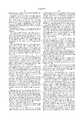
- FIG. 1illustrates a prior art water track, such as the water track of the #372 Polisher manufactured by IPEC Western Inc. of Phoenix, Ariz., USA.
- the water tracklabeled 10
- the water trackcomprises a frame 12 and a base 14.
- Frame 12has jet holes 16 connected to jets (not shown) which emit streams 18 of water through holes 16.
- Base 14has holes 20 connected to bubblers (not shown) which bubble small amounts of water 22 through holes 20.
- Streams 18, from the water jetsserve to force the wafer 25 in the direction indicated by arrow 24.
- Small streams 22push the wafer 25 slightly away from the base 14 and ensure that, while the wafer 25 moves through the track, it never rubs against base 14 and thus, the pattern on the wafer is not scratched.
- polisherswhose exit stations are formed just of the cassettes.
- Such a polisheris the 6DS-SP polisher of R. Howard Strasbaugh Inc. San Luis Obispo, Calif., USA.
- the present inventionincludes an optical system, which views the wafer through a window in the exit station, and a gripping system, which places the wafer in a predetermined viewing location within the exit station while maintaining the patterned surface completely under water.
- the present inventionalso includes a pull-down unit for pulling the measurement system slightly below the horizontal prior to the measurement and returns the measuring system to horizontal afterwards.
- the gripping systemincludes a raisable gate which collects the wafer in a predetermined location, and a gripper which grips the wafer, carries it to the viewing location and immerses the wafer, along a small angle to the horizontal, in the water.
- the gripperalso holds the wafer in place during the measurement operation, after which, it releases the wafer and the raisable gate is raised.
- the present inventionincorporates the method of immersing an object into water such that very few bubbles are produced on the wafer surface.
- the method of the present inventionpreferably includes the step of immersing the object while it is held such that its surface plane is at a small angle to the horizontal.
- the measurement systemincludes a water bath and a gripping system thereabove.
- the gripping systemincludes wafer holding elements, which receive the wafer, and a gripper whose initial location is above the expected reception location of the wafer.
- the gripperis flexibly connected at an angle to a piston such that the wafer is immersed in the water at an angle to the horizontal.
- FIG. 1is a schematic illustration of a prior art water track
- FIG. 2is a schematic illustration of a measurement system installable within a polishing machine, the measurement system being constructed and operative in accordance with a preferred embodiment of the present invention
- FIGS. 3, 4, 5, 6, 7 and 8are schematic, side view illustrations of a gripping system forming part of the measurement system of FIG. 2 in various stages of operation;
- FIG. 9is a schematic illustration of an example optical system forming part of the measurement system of the present invention.
- FIG. 10is a top view of a second embodiment of the measurement system of the present invention.
- FIGS. 11, 12 and 13are side views of the measurement system during receipt, transfer and measurement of the wafer, respectively.
- FIG. 2illustrates a measurement unit installable within a polishing machine, such as the IPEC Westech machine, the measurement system being constructed and operative in accordance with a preferred embodiment of the present invention and to FIGS. 3, 4, 5, 6, 7 and 8 which illustrate the operation of a gripping system forming part of the measurement system of FIG. 2. Similar reference numerals are utilized to refer to elements of the water track previously discussed.
- the measurement systemlabeled 30, comprises an optical system 32 and a gripping system 34 operative in conjunction with a water track 36.
- the optical system 32can be any optical system which measures the thickness of the top layer of the wafer through water.
- FIG. 9provides one example of such a optical system; other optical systems are also incorporated into the present invention.
- the gripping system 34comprises a raisable gate 40, a translatable gripper 42, a vacuum pad 44 and a vacuum system 46.
- Gate 40is controlled by a lifting mechanism 48 which raises and lowers gate 40 as necessary.
- Gate 40has an upper surface 50 with a curved outer edge 52 and a plurality of protrusions 54 extending downward into the water from the upper surface 50.
- Protrusions 54provide a lower surface onto which the gate 40 is lowered while enabling the water to pass through the gate 40.
- Curved edge 52is shaped to match the curved edge of the wafer 25 so that, when gate 40 is in its lowered position, gate 40 will both keep the wafer 25 from passing out of the water track and to hold the wafer 25 in a repeatable location.
- Gripper 42translates between the wafer collecting position defined by the curved edge 52 and a wafer measuring location indicated in FIG. 2 by the wafer 25.
- the base of the water track at the wafer measuring locationhas been replaced by a window 60 (FIGS. 3-9) to enable the optical system 32 to view the patterned surface 62 of the wafer 25.
- the patterned surface 62is shown exaggeratedly in the Figures.
- Gripper 42can be translated by any translation system; an example of one such system is provided in FIG. 2 and labeled 64.
- the vacuum pad 44is typically a bellows-shaped pad and is mounted at the end of the gripper 42 and is connected to the vacuum system 46.
- the vacuum pad 44creates a suction so that gripper 42 can raise the wafer 25 and move it from the wafer collecting position to the wafer measuring location. In addition, the vacuum is maintained during the measurement and only released once the measurement is complete.
- FIGS. 3-8illustrate the operation of the gripping system 34.
- the jets, labeled 70, and the bubblers, labeled 72, of the water trackare operated and the gate 40 is lowered.
- the polisher(not shown) places the wafer 25 within the water track and the streams 18 from the jets 70 push the wafer 25 towards the gate 40.
- the gripper 42is at the wafer collecting position, shown to the left in FIGS. 3-8.
- gripper 42lowers vacuum pad 44 to grab the wafer 25.
- gripper 42can be formed of any suitable mechanism, such as a piston, which can move vacuum pad 44 up and down on command. Since bubblers 72 are operating, the small streams 22 maintain the wafer 25 away from the base 14 of the water track.
- the gripper 42then pulls the wafer 25 out of the water (FIG. 5) and the jets 70 are deactivated.
- the axis 74 of symmetry of the vacuum pad 44is formed at a small angle a from the vertical axis 76.
- a long axis 75 of the wafer 25is at the same small angle a to the horizontal axis 78.
- Angle ⁇is typically in the range of 2-5°.
- Translation unit 64then moves gripper 42 to the wafer measuring position, shown to the right in FIGS. 4-8.
- a pull-down mechanismslightly lowers the entire water track, gripping and optical system unit (at an angle of 1-3°), about a hinge 80 (FIGS. 2-8), to force the water toward the wafer measuring position.
- Other methods of forcing the water towards the measuring positionare also incorporated in the present invention.
- gripper 42After the lowering of the water track, gripper 42 lowers the wafer 25 towards the window 60. Since the vacuum pad 44 is angled, the wafer 25 does not enter the water all at once. Instead, wafer 25 enters the water gradually. Initially, only the side labeled 82 is immersed. As the gripper 42 pushes the vacuum pad 44 further down, more and more of the wafer 25 becomes immersed until the entire wafer 25 is within the water. Vacuum pad 44 is flexible enough to accommodate the changed angle of wafer 25.
- the wafer 25does not rest against the window 60. Instead, it is held against protruding surfaces 84 such that there is a layer of water 86 between the wafer 25 and window 60. Due to the gradual immersion of wafer 25, layer 86 of water has little, if any, bubbles in it and therefore provides a uniform connecting medium between the optical system 32 and the patterned surface 62 of wafer 25.
- gripper 42returns vacuum pad 44, with wafer 25 still attached, to its upper position.
- the pull-down mechanismrotates the water track about hinge 80 to return to its original position, gate 40 is raised, and jets 70 and bubblers 72 are activated.
- the vacuum system 46releases the vacuum and the wafer 25 falls into the water track.
- the flow of watercauses the wafer 25 to move toward and under the now raised gate 40.
- a sensor 90determines when the wafer 25 successfully passes out of the water track. The process described hereinabove can now begin for the next wafer.
- Optical system 32is a microscope-based spectrophotometer and comprises an objective lens 100, a focusing lens 102, a beam splitter 104, a pin hole mirror 106, a relay lens 108 and a spectrophotometer 110. It additionally comprises a light source 112, a condenser 114, a charge coupled device (CCD) camera 116 and a second relay lens 118.
- CCDcharge coupled device
- Light from light source 112is provided, along an optical fiber 113, to condenser 114.
- condenser 114directs the light towards beam splitter 104.
- Beam splitter 104directs the light towards the wafer surface via lenses 102 and 100 and via window 60 and water layer 86.
- the reflected light from the patterned surface 62is collected by objective 100 and focused, by lens 102, onto pin hole mirror 106.
- Relay lens 108receives the light passed through pin hole mirror 106 and focuses it onto the spectrophotometer 110.
- Pin hole mirror 106passes light through its hole towards spectrophotometer 110 and directs the light hitting the mirror surface towards CCD camera 116.
- Second relay lens 118receives the light reflected by pin hole mirror 106 and focusses it onto the CCD camera 116.
- Relay lens 108collects the light from the pinhole and provides it to spectrophotometer 110.
- Relay lens 118collects the light and focuses it onto the CCD camera 116.
- the pinholeserves to locate the measurement spot in the image of the wafer 25. Since the pinhole allows light to pass through it, rather than being reflected toward the CCD camera 116, the pinhole appears as a sharp dark point in the image produced by the lens 118. Thus, when viewing the CCD image, the location of the measurement spot is immediately known, it being the location of the dark spot.
- FIGS. 10-13illustrate the thickness measuring of the present invention implemented in a polishing machine similar to that produced by Strasbaugh which has no water track.
- the polishing machine or an external robotbrings the wafers 25 to an exit station of the polisher.
- the robotbrings the wafers 25 to their cassette at another exit station.
- FIG. 10is a top view and FIGS. 11, 12 and 13 illustrate the measuring station in three states.
- the measuring station 130comprises a gripping unit 132, an optical system 134 and a water bath 136.
- the optical system 134is located beneath the water bath 136 and can be any suitable optical system, such as the one described hereinabove.
- the water bath 136has a window in its bottom surface, labeled 140 in FIG. 11, through which the optical system 134 can illuminate the wafer 25.
- the gripping unit 132comprises a wafer support 150, illustrated as being formed of two support elements, a vacuum pad 152, similar to vacuum pad 44, and a piston 160.
- the polisherplaces the wafer 25 on the wafer support 150 while the vacuum pad 152 is initially in a position above the support 150, as shown in FIG. 11.
- the vacuum pad 152which is controlled by piston 160, moves toward the wafer and grabs it by applying a vacuum. Now that the vacuum pad 152 is holding the wafer, the wafer supports 150 move away, as indicated.
- the piston 160then pushes the vacuum pad-wafer combination toward the water bath 136.
- FIG. 12which also illustrates that the vacuum pad 152 holds the wafer 25 at a small angle ⁇ to the horizontal.
- the angle ⁇is provided since, as in the previous embodiment, the axis of symmetry of the vacuum pad 152 is formed at a small angle ⁇ from the vertical axis.
- by immersing the wafer 25 into the water at the angle ⁇few, if any, bubbles, remain on the undersurface of the wafer after full immersion.
- FIG. 13illustrates the wafer 25 at its fully immersed, measurement position.
- wafer 25does not directly touch the water surface 163 of the window 140; instead, it sits on a measurement support 168. The result is that there is a water layer 164 between the wafer 25 and the surface 163 of the window.
- the piston 160returns the wafer 25 to its original position and the wafer support elements 150 return to their wafer receiving position.
- the piston 160places the wafer 25 on the wafer support elements 150 and releases the vacuum.
- the external robotcan now take the wafer to another exit station where there is a cassette of processed and measured wafers.
Landscapes
- Engineering & Computer Science (AREA)
- Manufacturing & Machinery (AREA)
- Computer Hardware Design (AREA)
- Microelectronics & Electronic Packaging (AREA)
- Power Engineering (AREA)
- Mechanical Engineering (AREA)
- Condensed Matter Physics & Semiconductors (AREA)
- General Physics & Mathematics (AREA)
- Physics & Mathematics (AREA)
- Mechanical Treatment Of Semiconductor (AREA)
- Testing Or Measuring Of Semiconductors Or The Like (AREA)
- Constituent Portions Of Griding Lathes, Driving, Sensing And Control (AREA)
- Length Measuring Devices By Optical Means (AREA)
Abstract
Description
The present invention relates to wafer polishing apparatus in general and to measuring systems incorporated into such apparatus in particular.
Wafer polishing systems are known in the art. They polish the top layer of semiconductor wafers to a desired thickness. To do so, the wafer being polished is immersed in a slurry of water and chemicals during the polishing process. Once the wafer has been polished and washed down, it is placed into an exit station known by some companies as a "water track", after which the wafer is placed into a cassette of wafers. The cassette is maintained within a water bath until full, after which the entire cassette is brought to a cleaning station to remove any chemicals and slurry particles still remaining on the wafers in the cassette and to dry the wafers. After cleaning, the wafers are brought to a measurement station to determine if the polisher produced the desired thickness of their top layers.
FIG. 1, to which reference is now briefly made, illustrates a prior art water track, such as the water track of the #372 Polisher manufactured by IPEC Western Inc. of Phoenix, Ariz., USA. The water track, labeled 10, comprises a frame 12 and a base 14. Frame 12 has jet holes 16 connected to jets (not shown) which emit streams 18 of water through holes 16. Base 14 hasholes 20 connected to bubblers (not shown) which bubble small amounts of water 22 throughholes 20. When awafer 25 is dropped into water track 10, pattern-side down, the jets and bubblers are activated. Streams 18, from the water jets, serve to force thewafer 25 in the direction indicated by arrow 24. Small streams 22 push thewafer 25 slightly away from the base 14 and ensure that, while thewafer 25 moves through the track, it never rubs against base 14 and thus, the pattern on the wafer is not scratched.
Other companies produce polishers whose exit stations are formed just of the cassettes. Such a polisher is the 6DS-SP polisher of R. Howard Strasbaugh Inc. San Luis Obispo, Calif., USA.
It is an object of the present invention to provide a measurement system installable within a polishing machine and, more specifically, within the exit station of a polishing machine.
In accordance with a preferred embodiment of the present invention, the present invention includes an optical system, which views the wafer through a window in the exit station, and a gripping system, which places the wafer in a predetermined viewing location within the exit station while maintaining the patterned surface completely under water. The present invention also includes a pull-down unit for pulling the measurement system slightly below the horizontal prior to the measurement and returns the measuring system to horizontal afterwards.
In accordance with a first preferred embodiment of the present invention, the gripping system includes a raisable gate which collects the wafer in a predetermined location, and a gripper which grips the wafer, carries it to the viewing location and immerses the wafer, along a small angle to the horizontal, in the water. The gripper also holds the wafer in place during the measurement operation, after which, it releases the wafer and the raisable gate is raised.
The present invention incorporates the method of immersing an object into water such that very few bubbles are produced on the wafer surface. The method of the present invention preferably includes the step of immersing the object while it is held such that its surface plane is at a small angle to the horizontal.
In a second embodiment, the measurement system includes a water bath and a gripping system thereabove. The gripping system includes wafer holding elements, which receive the wafer, and a gripper whose initial location is above the expected reception location of the wafer. The gripper is flexibly connected at an angle to a piston such that the wafer is immersed in the water at an angle to the horizontal.
The present invention will be understood and appreciated more fully from the following detailed description taken in conjunction with the drawings in which:
FIG. 1 is a schematic illustration of a prior art water track;
FIG. 2 is a schematic illustration of a measurement system installable within a polishing machine, the measurement system being constructed and operative in accordance with a preferred embodiment of the present invention;
FIGS. 3, 4, 5, 6, 7 and 8 are schematic, side view illustrations of a gripping system forming part of the measurement system of FIG. 2 in various stages of operation;
FIG. 9 is a schematic illustration of an example optical system forming part of the measurement system of the present invention;
FIG. 10 is a top view of a second embodiment of the measurement system of the present invention; and
FIGS. 11, 12 and 13 are side views of the measurement system during receipt, transfer and measurement of the wafer, respectively.
Reference is now made to FIG. 2, which illustrates a measurement unit installable within a polishing machine, such as the IPEC Westech machine, the measurement system being constructed and operative in accordance with a preferred embodiment of the present invention and to FIGS. 3, 4, 5, 6, 7 and 8 which illustrate the operation of a gripping system forming part of the measurement system of FIG. 2. Similar reference numerals are utilized to refer to elements of the water track previously discussed.
The measurement system, labeled 30, comprises anoptical system 32 and a gripping system 34 operative in conjunction with a water track 36. Theoptical system 32 can be any optical system which measures the thickness of the top layer of the wafer through water. FIG. 9 provides one example of such a optical system; other optical systems are also incorporated into the present invention.
The gripping system 34 comprises araisable gate 40, atranslatable gripper 42, avacuum pad 44 and avacuum system 46.Gate 40 is controlled by a lifting mechanism 48 which raises and lowersgate 40 as necessary.Gate 40 has anupper surface 50 with a curved outer edge 52 and a plurality of protrusions 54 extending downward into the water from theupper surface 50. Protrusions 54 provide a lower surface onto which thegate 40 is lowered while enabling the water to pass through thegate 40. Curved edge 52 is shaped to match the curved edge of thewafer 25 so that, whengate 40 is in its lowered position,gate 40 will both keep thewafer 25 from passing out of the water track and to hold thewafer 25 in a repeatable location.
Gripper 42 can be translated by any translation system; an example of one such system is provided in FIG. 2 and labeled 64.
Thevacuum pad 44 is typically a bellows-shaped pad and is mounted at the end of thegripper 42 and is connected to thevacuum system 46. Thevacuum pad 44 creates a suction so thatgripper 42 can raise thewafer 25 and move it from the wafer collecting position to the wafer measuring location. In addition, the vacuum is maintained during the measurement and only released once the measurement is complete.
FIGS. 3-8 illustrate the operation of the gripping system 34. Initially, and as shown in FIG. 3, the jets, labeled 70, and the bubblers, labeled 72, of the water track are operated and thegate 40 is lowered. The polisher (not shown) places thewafer 25 within the water track and the streams 18 from the jets 70 push thewafer 25 towards thegate 40. Thegripper 42 is at the wafer collecting position, shown to the left in FIGS. 3-8.
Once thewafer 25 is in the wafer collecting position, as shown in FIG. 4,gripper 42 lowersvacuum pad 44 to grab thewafer 25. It will be appreciated thatgripper 42 can be formed of any suitable mechanism, such as a piston, which can movevacuum pad 44 up and down on command. Since bubblers 72 are operating, the small streams 22 maintain thewafer 25 away from the base 14 of the water track.
Thegripper 42 then pulls thewafer 25 out of the water (FIG. 5) and the jets 70 are deactivated. In accordance with a preferred embodiment of the present invention, the axis 74 of symmetry of thevacuum pad 44 is formed at a small angle a from the vertical axis 76. As a result, a long axis 75 of thewafer 25 is at the same small angle a to the horizontal axis 78. Angle α is typically in the range of 2-5°.
Translation unit 64 then movesgripper 42 to the wafer measuring position, shown to the right in FIGS. 4-8. At the same time and as shown in FIG. 6, a pull-down mechanism slightly lowers the entire water track, gripping and optical system unit (at an angle of 1-3°), about a hinge 80 (FIGS. 2-8), to force the water toward the wafer measuring position. Other methods of forcing the water towards the measuring position are also incorporated in the present invention.
After the lowering of the water track,gripper 42 lowers thewafer 25 towards thewindow 60. Since thevacuum pad 44 is angled, thewafer 25 does not enter the water all at once. Instead,wafer 25 enters the water gradually. Initially, only the side labeled 82 is immersed. As thegripper 42 pushes thevacuum pad 44 further down, more and more of thewafer 25 becomes immersed until theentire wafer 25 is within the water.Vacuum pad 44 is flexible enough to accommodate the changed angle ofwafer 25.
It will be appreciated that, by gradually immersing the wafer in the water, few, if any, bubbles are created near the patterned surface of thewafer 25.
It is noted that thewafer 25 does not rest against thewindow 60. Instead, it is held against protruding surfaces 84 such that there is a layer ofwater 86 between thewafer 25 andwindow 60. Due to the gradual immersion ofwafer 25,layer 86 of water has little, if any, bubbles in it and therefore provides a uniform connecting medium between theoptical system 32 and the patternedsurface 62 ofwafer 25.
Once theoptical system 32 has finished measuring the patternedsurface 62 ofwafer 25,gripper 42returns vacuum pad 44, withwafer 25 still attached, to its upper position. The pull-down mechanism rotates the water track about hinge 80 to return to its original position,gate 40 is raised, and jets 70 and bubblers 72 are activated. Thevacuum system 46 releases the vacuum and thewafer 25 falls into the water track. The flow of water causes thewafer 25 to move toward and under the now raisedgate 40. A sensor 90 determines when thewafer 25 successfully passes out of the water track. The process described hereinabove can now begin for the next wafer.
Reference is now made to FIG. 9 which schematically illustrates an example of a suitableoptical system 32.Optical system 32 is a microscope-based spectrophotometer and comprises an objective lens 100, a focusing lens 102, a beam splitter 104, a pin hole mirror 106, a relay lens 108 and a spectrophotometer 110. It additionally comprises a light source 112, a condenser 114, a charge coupled device (CCD) camera 116 and a second relay lens 118.
Light from light source 112 is provided, along an optical fiber 113, to condenser 114. In turn, condenser 114 directs the light towards beam splitter 104. Beam splitter 104 directs the light towards the wafer surface via lenses 102 and 100 and viawindow 60 andwater layer 86.
The reflected light from the patternedsurface 62 is collected by objective 100 and focused, by lens 102, onto pin hole mirror 106. Relay lens 108 receives the light passed through pin hole mirror 106 and focuses it onto the spectrophotometer 110.
Pin hole mirror 106 passes light through its hole towards spectrophotometer 110 and directs the light hitting the mirror surface towards CCD camera 116. Second relay lens 118 receives the light reflected by pin hole mirror 106 and focusses it onto the CCD camera 116.
Since the pinhole is placed at the center of the image plane which is the focal plane of lens 102, it acts as an aperture stop, allowing only the collimated portion of the light beam to pass through. Thus, the pinhole drastically reduces any scattered light in the system. Relay lens 108 collects the light from the pinhole and provides it to spectrophotometer 110.
Furthermore, since the pinhole is located at the image plane of the optical imaging system (lenses 100 and 102), only that portion of the light, reflected from the surface ofwafer 25, which is the size of the pinhole divided by the magnification will come through the pinhole. Relay lens 118 collects the light and focuses it onto the CCD camera 116.
The pinhole serves to locate the measurement spot in the image of thewafer 25. Since the pinhole allows light to pass through it, rather than being reflected toward the CCD camera 116, the pinhole appears as a sharp dark point in the image produced by the lens 118. Thus, when viewing the CCD image, the location of the measurement spot is immediately known, it being the location of the dark spot.
Reference is now made to FIGS. 10-13 which illustrate the thickness measuring of the present invention implemented in a polishing machine similar to that produced by Strasbaugh which has no water track. In this embodiment, the polishing machine or an external robot (not shown) brings thewafers 25 to an exit station of the polisher. When the measurement has finished, the robot brings thewafers 25 to their cassette at another exit station. FIG. 10 is a top view and FIGS. 11, 12 and 13 illustrate the measuring station in three states.
The measuring station 130 comprises agripping unit 132, anoptical system 134 and awater bath 136. Theoptical system 134 is located beneath thewater bath 136 and can be any suitable optical system, such as the one described hereinabove. As in the previous embodiment, thewater bath 136 has a window in its bottom surface, labeled 140 in FIG. 11, through which theoptical system 134 can illuminate thewafer 25.
Thegripping unit 132 comprises awafer support 150, illustrated as being formed of two support elements, avacuum pad 152, similar tovacuum pad 44, and apiston 160. The polisher places thewafer 25 on thewafer support 150 while thevacuum pad 152 is initially in a position above thesupport 150, as shown in FIG. 11. Once thewafer support 150 has the wafer in a predefined position, thevacuum pad 152, which is controlled bypiston 160, moves toward the wafer and grabs it by applying a vacuum. Now that thevacuum pad 152 is holding the wafer, the wafer supports 150 move away, as indicated.
Thepiston 160 then pushes the vacuum pad-wafer combination toward thewater bath 136. This is shown in FIG. 12 which also illustrates that thevacuum pad 152 holds thewafer 25 at a small angle α to the horizontal. The angle α is provided since, as in the previous embodiment, the axis of symmetry of thevacuum pad 152 is formed at a small angle α from the vertical axis. As in the previous embodiment, by immersing thewafer 25 into the water at the angle α, few, if any, bubbles, remain on the undersurface of the wafer after full immersion.
FIG. 13 illustrates thewafer 25 at its fully immersed, measurement position. Typically,wafer 25 does not directly touch thewater surface 163 of thewindow 140; instead, it sits on ameasurement support 168. The result is that there is awater layer 164 between thewafer 25 and thesurface 163 of the window.
Once the measurement process has finished, thepiston 160 returns thewafer 25 to its original position and thewafer support elements 150 return to their wafer receiving position. Thepiston 160 places thewafer 25 on thewafer support elements 150 and releases the vacuum. The external robot can now take the wafer to another exit station where there is a cassette of processed and measured wafers.
It will be appreciated by persons skilled in the art that the present invention is not limited to what has been particularly shown and described hereinabove. Rather the scope of the present invention is defined by the claims which follow:
Claims (4)
1. A thickness measuring unit for mounting on a water track of a polisher for measuring the thickness of a top layer of a wafer, said thickness measuring unit comprising:
a. a curved gate having a radius of curvature generally similar to that of said wafer, said curved gate being located at a gripping position;
b. a window mounted in a bottom surface of said water track;
c. a gripper for moving said wafer from said gripping position to a measuring position above a layer of water located above said window, said gripper including a gripping pad, having a planar surface wherein said planar surface of said gripping pad is at an angle to a horizontal plane; and
d. an optical system, mounted underneath said window, for measuring said thickness of said top layer through said window and said layer of water.
2. A thickness measuring unit for mounting on a water bath for measuring the thickness of a top layer of a wafer, said thickness measuring unit comprising:
a. a window mounted in a bottom surface of said water bath;
b. a gripper for moving said wafer from a gripping position above said water bath to a measuring position above a layer of water located above said window, said gripper including a gripping pad having a planar surface, wherein said planar surface of said gripping pad is at an angle to a horizontal plane; and
c. an optical system, mounted underneath said window, for measuring said thickness of said top layer through said window and said layer of water.
3. A method of measuring the thickness of a polished top layer of a wafer before removing said wafer from a polishing machine, said method comprising the steps of:
a. picking said wafer up from a gripping position;
b. moving said wafer from said gripping position to a measuring position;
c. immersing said wafer within a bath of water over said measuring position such that a plane defined by the circumference of said wafer is at an angle to a surface of said water;
d. placing said wafer in said measuring position underneath a surface of said water and above a window but with a thin layer of said water between said wafer and said window; and
e. measuring said thickness of said top layer through said window and said thin layer of water.
4. A method according to claim 3 wherein said water is held within a water bath and wherein said step of moving comprises the step of rotating the plane of a lower surface of said water bath from a relatively horizontal plane to one which causes said water to move towards said measuring position.
Priority Applications (3)
| Application Number | Priority Date | Filing Date | Title |
|---|---|---|---|
| US09/047,944US5957749A (en) | 1995-05-23 | 1998-03-25 | Apparatus for optical inspection of wafers during polishing |
| US09/498,926US6368181B1 (en) | 1995-05-23 | 2000-02-04 | Apparatus for optical inspection of wafers during polishing |
| US09/898,467US6752689B2 (en) | 1995-05-23 | 2001-07-05 | Apparatus for optical inspection of wafers during polishing |
Applications Claiming Priority (2)
| Application Number | Priority Date | Filing Date | Title |
|---|---|---|---|
| IL11382995AIL113829A (en) | 1995-05-23 | 1995-05-23 | Apparatus for optical inspection of wafers during polishing |
| IL113829 | 1995-05-23 |
Related Child Applications (2)
| Application Number | Title | Priority Date | Filing Date |
|---|---|---|---|
| US09/047,944ContinuationUS5957749A (en) | 1995-05-23 | 1998-03-25 | Apparatus for optical inspection of wafers during polishing |
| US09/498,926ContinuationUS6368181B1 (en) | 1995-05-23 | 2000-02-04 | Apparatus for optical inspection of wafers during polishing |
Publications (1)
| Publication Number | Publication Date |
|---|---|
| US6045433Atrue US6045433A (en) | 2000-04-04 |
Family
ID=11067506
Family Applications (5)
| Application Number | Title | Priority Date | Filing Date |
|---|---|---|---|
| US08/497,382Expired - LifetimeUS6045433A (en) | 1995-05-23 | 1995-06-29 | Apparatus for optical inspection of wafers during polishing |
| US09/047,944Expired - LifetimeUS5957749A (en) | 1995-05-23 | 1998-03-25 | Apparatus for optical inspection of wafers during polishing |
| US09/498,926Expired - LifetimeUS6368181B1 (en) | 1995-05-23 | 2000-02-04 | Apparatus for optical inspection of wafers during polishing |
| US09/898,467Expired - LifetimeUS6752689B2 (en) | 1995-05-23 | 2001-07-05 | Apparatus for optical inspection of wafers during polishing |
| US12/188,624AbandonedUS20080297794A1 (en) | 1995-05-23 | 2008-08-08 | Apparatus for optical inspection of wafers during polishing |
Family Applications After (4)
| Application Number | Title | Priority Date | Filing Date |
|---|---|---|---|
| US09/047,944Expired - LifetimeUS5957749A (en) | 1995-05-23 | 1998-03-25 | Apparatus for optical inspection of wafers during polishing |
| US09/498,926Expired - LifetimeUS6368181B1 (en) | 1995-05-23 | 2000-02-04 | Apparatus for optical inspection of wafers during polishing |
| US09/898,467Expired - LifetimeUS6752689B2 (en) | 1995-05-23 | 2001-07-05 | Apparatus for optical inspection of wafers during polishing |
| US12/188,624AbandonedUS20080297794A1 (en) | 1995-05-23 | 2008-08-08 | Apparatus for optical inspection of wafers during polishing |
Country Status (5)
| Country | Link |
|---|---|
| US (5) | US6045433A (en) |
| JP (2) | JPH09109023A (en) |
| DE (1) | DE19612195A1 (en) |
| FR (1) | FR2734631B1 (en) |
| IL (1) | IL113829A (en) |
Cited By (28)
| Publication number | Priority date | Publication date | Assignee | Title |
|---|---|---|---|---|
| US6292265B1 (en)* | 1999-03-10 | 2001-09-18 | Nova Measuring Instruments Ltd. | Method and apparatus for monitoring a chemical mechanical planarization process applied to metal-based patterned objects |
| US6364386B1 (en)* | 1999-10-27 | 2002-04-02 | Agilent Technologies, Inc. | Apparatus and method for handling an integrated circuit |
| US6368182B2 (en)* | 2000-02-04 | 2002-04-09 | Nova Measuring Instruments Ltd. | Apparatus for optical inspection of wafers during polishing |
| US20020103564A1 (en)* | 2000-09-20 | 2002-08-01 | John Fielden | Methods and systems for determining a composition and a thickness of a specimen |
| US20020107650A1 (en)* | 2000-09-20 | 2002-08-08 | Dan Wack | Methods and systems for determining a critical dimension and a presence of defects on a specimen |
| US6489624B1 (en)* | 1997-07-18 | 2002-12-03 | Nikon Corporation | Apparatus and methods for detecting thickness of a patterned layer |
| US6572456B2 (en) | 2000-08-11 | 2003-06-03 | Sensys Instruments Corporation | Bathless wafer measurement apparatus and method |
| US6623331B2 (en) | 2001-02-16 | 2003-09-23 | Cabot Microelectronics Corporation | Polishing disk with end-point detection port |
| US20030181139A1 (en)* | 2002-02-04 | 2003-09-25 | Kurt Lehman | Windows configurable to be coupled to a process tool or to be disposed within an opening in a polishing pad |
| US6657736B1 (en) | 1999-07-09 | 2003-12-02 | Nova Measuring Instruments Ltd. | Method and system for measuring patterned structures |
| US6673637B2 (en) | 2000-09-20 | 2004-01-06 | Kla-Tencor Technologies | Methods and systems for determining a presence of macro defects and overlay of a specimen |
| US6694284B1 (en) | 2000-09-20 | 2004-02-17 | Kla-Tencor Technologies Corp. | Methods and systems for determining at least four properties of a specimen |
| US20040042017A1 (en)* | 2002-06-26 | 2004-03-04 | Yoel Cohen | Thin films measurement method and system |
| US6801326B2 (en) | 1999-03-10 | 2004-10-05 | Nova Measuring Instruments Ltd. | Method and apparatus for monitoring a chemical mechanical planarization process applied to metal-based patterned objects |
| US6812045B1 (en) | 2000-09-20 | 2004-11-02 | Kla-Tencor, Inc. | Methods and systems for determining a characteristic of a specimen prior to, during, or subsequent to ion implantation |
| US6891627B1 (en) | 2000-09-20 | 2005-05-10 | Kla-Tencor Technologies Corp. | Methods and systems for determining a critical dimension and overlay of a specimen |
| US6919957B2 (en) | 2000-09-20 | 2005-07-19 | Kla-Tencor Technologies Corp. | Methods and systems for determining a critical dimension, a presence of defects, and a thin film characteristic of a specimen |
| US7106425B1 (en) | 2000-09-20 | 2006-09-12 | Kla-Tencor Technologies Corp. | Methods and systems for determining a presence of defects and a thin film characteristic of a specimen |
| US7130029B2 (en) | 2000-09-20 | 2006-10-31 | Kla-Tencor Technologies Corp. | Methods and systems for determining an adhesion characteristic and a thickness of a specimen |
| US7169015B2 (en) | 1995-05-23 | 2007-01-30 | Nova Measuring Instruments Ltd. | Apparatus for optical inspection of wafers during processing |
| US20070052977A1 (en)* | 1998-07-09 | 2007-03-08 | Acm Research, Inc. | Method and apparatus for end-point detection |
| US20070105029A1 (en)* | 2003-12-19 | 2007-05-10 | International Business Machines Corporation | Differential critical dimension and overlay metrology apparatus and measurement method |
| US20070123151A1 (en)* | 1995-05-23 | 2007-05-31 | Nova Measuring Instruments Ltd | Apparatus for optical inspection of wafers during polishing |
| US7349090B2 (en) | 2000-09-20 | 2008-03-25 | Kla-Tencor Technologies Corp. | Methods and systems for determining a property of a specimen prior to, during, or subsequent to lithography |
| US20080297794A1 (en)* | 1995-05-23 | 2008-12-04 | Nova Measuring Instruments Ltd | Apparatus for optical inspection of wafers during polishing |
| US20100265486A1 (en)* | 2009-02-22 | 2010-10-21 | Mapper Lithography Ip B.V. | Method of clamping a substrate and clamp preparation unit |
| US8531678B2 (en) | 1999-07-09 | 2013-09-10 | Nova Measuring Instruments, Ltd. | Method and system for measuring patterned structures |
| US10431505B2 (en)* | 2016-06-07 | 2019-10-01 | Samsung Electronics Co., Ltd. | Method of inspecting surface having a minute pattern based on detecting light reflected from metal layer on the surface |
Families Citing this family (25)
| Publication number | Priority date | Publication date | Assignee | Title |
|---|---|---|---|---|
| US6599412B1 (en)* | 1997-09-30 | 2003-07-29 | Semitool, Inc. | In-situ cleaning processes for semiconductor electroplating electrodes |
| JPH11207610A (en)* | 1998-01-26 | 1999-08-03 | Speedfam Co Ltd | Grinding amount control system and method for the same |
| US6217425B1 (en)* | 1998-06-12 | 2001-04-17 | Tdk Corporation | Apparatus and method for lapping magnetic heads |
| US6320609B1 (en)* | 1998-07-10 | 2001-11-20 | Nanometrics Incorporated | System using a polar coordinate stage and continuous image rotation to compensate for stage rotation |
| US7295314B1 (en) | 1998-07-10 | 2007-11-13 | Nanometrics Incorporated | Metrology/inspection positioning system |
| US7177019B2 (en)* | 1999-02-01 | 2007-02-13 | Tokyo Electron Limited | Apparatus for imaging metrology |
| US7042580B1 (en) | 1999-02-01 | 2006-05-09 | Tokyo Electron Limited | Apparatus for imaging metrology |
| DE19922919C2 (en) | 1999-05-19 | 2002-01-17 | Infineon Technologies Ag | Plant for processing wafers |
| WO2001012384A2 (en)* | 1999-08-12 | 2001-02-22 | Speedfam-Ipec Corporation | Apparatus for moving a workpiece |
| CN100469948C (en)* | 2000-10-03 | 2009-03-18 | 应用材料有限公司 | Method and associated apparatus for tilting a substrate once entering metal deposition |
| JP4348412B2 (en)* | 2001-04-26 | 2009-10-21 | 東京エレクトロン株式会社 | Measurement system cluster |
| WO2002091248A1 (en)* | 2001-05-04 | 2002-11-14 | Therma-Wave, Inc. | Systems and methods for metrology recipe and model generation |
| US6854948B1 (en) | 2002-08-15 | 2005-02-15 | Nanometrics Incorporated | Stage with two substrate buffer station |
| IL156330A (en)* | 2003-06-05 | 2009-12-24 | Nova Measuring Instr Ltd | Article transfer system |
| US7085676B2 (en)* | 2003-06-27 | 2006-08-01 | Tokyo Electron Limited | Feed forward critical dimension control |
| IL158086A (en)* | 2003-09-24 | 2010-02-17 | Nova Measuring Instr Ltd | Method and system for positioning articles with respect to a processing tool |
| US7362448B1 (en) | 2004-09-08 | 2008-04-22 | Nanometrics Incorporated | Characterizing residue on a sample |
| WO2007103780A2 (en)* | 2006-03-03 | 2007-09-13 | Edgecraft Corporation | Improved sharpener for blades of food slicers |
| JP4926528B2 (en)* | 2006-04-19 | 2012-05-09 | 昭和電工株式会社 | Wet polishing equipment |
| US20080024772A1 (en)* | 2006-07-26 | 2008-01-31 | Seagate Technology Llc | Particle removal tool with integrated defect detection/analysis capability |
| JP6046933B2 (en) | 2012-07-10 | 2016-12-21 | 株式会社荏原製作所 | Polishing method |
| US10565701B2 (en) | 2015-11-16 | 2020-02-18 | Applied Materials, Inc. | Color imaging for CMP monitoring |
| US11557048B2 (en) | 2015-11-16 | 2023-01-17 | Applied Materials, Inc. | Thickness measurement of substrate using color metrology |
| CN107703881B (en)* | 2017-09-11 | 2023-08-04 | 中国工程物理研究院机械制造工艺研究所 | Device for automatically calibrating thickness of magnetorheological polishing ribbon |
| US11100628B2 (en) | 2019-02-07 | 2021-08-24 | Applied Materials, Inc. | Thickness measurement of substrate using color metrology |
Citations (10)
| Publication number | Priority date | Publication date | Assignee | Title |
|---|---|---|---|---|
| US4018638A (en)* | 1975-08-22 | 1977-04-19 | North American Philips Corporation | Method of reducing the thickness of a wafer of fragile material |
| US4793895A (en)* | 1988-01-25 | 1988-12-27 | Ibm Corporation | In situ conductivity monitoring technique for chemical/mechanical planarization endpoint detection |
| US5081421A (en)* | 1990-05-01 | 1992-01-14 | At&T Bell Laboratories | In situ monitoring technique and apparatus for chemical/mechanical planarization endpoint detection |
| US5081796A (en)* | 1990-08-06 | 1992-01-21 | Micron Technology, Inc. | Method and apparatus for mechanical planarization and endpoint detection of a semiconductor wafer |
| US5125740A (en)* | 1989-03-17 | 1992-06-30 | Hitachi, Ltd. | Method and apparatus for measuring optical constants of a thin film as well as method and apparatus for fabricating a thin film utilizing same |
| US5157877A (en)* | 1990-04-27 | 1992-10-27 | Shin-Etsu Handotai Co., Ltd. | Method for preparing a semiconductor wafer |
| US5240552A (en)* | 1991-12-11 | 1993-08-31 | Micron Technology, Inc. | Chemical mechanical planarization (CMP) of a semiconductor wafer using acoustical waves for in-situ end point detection |
| US5337015A (en)* | 1993-06-14 | 1994-08-09 | International Business Machines Corporation | In-situ endpoint detection method and apparatus for chemical-mechanical polishing using low amplitude input voltage |
| US5433651A (en)* | 1993-12-22 | 1995-07-18 | International Business Machines Corporation | In-situ endpoint detection and process monitoring method and apparatus for chemical-mechanical polishing |
| US5492594A (en)* | 1994-09-26 | 1996-02-20 | International Business Machines Corp. | Chemical-mechanical polishing tool with end point measurement station |
Family Cites Families (69)
| Publication number | Priority date | Publication date | Assignee | Title |
|---|---|---|---|---|
| US3156073A (en) | 1963-01-15 | 1964-11-10 | Ray H Strasbaugh | Irregular, non-repetitive, closed-loop surfacing mechanism |
| US3564776A (en) | 1969-04-16 | 1971-02-23 | Itek Corp | Optical surface generating method and apparatus |
| FR2097216A5 (en) | 1970-05-27 | 1972-03-03 | Anvar | |
| US3841031A (en) | 1970-10-21 | 1974-10-15 | Monsanto Co | Process for polishing thin elements |
| US3691694A (en) | 1970-11-02 | 1972-09-19 | Ibm | Wafer polishing machine |
| US4050954A (en) | 1976-03-25 | 1977-09-27 | International Business Machines Corporation | Surface treatment of semiconductor substrates |
| US4083272A (en) | 1976-12-14 | 1978-04-11 | The United States Of America As Represented By The United States Department Of Energy | Omega-X micromachining system |
| US4193226A (en) | 1977-09-21 | 1980-03-18 | Kayex Corporation | Polishing apparatus |
| ZA813263B (en)* | 1980-06-04 | 1982-06-30 | De Beers Cons Mines Ltd | The assessment of colour in diamonds and other gems |
| JPS5815265B2 (en)* | 1980-09-01 | 1983-03-24 | 日本電信電話株式会社 | Automatic shape correction polishing equipment |
| US4365301A (en) | 1980-09-12 | 1982-12-21 | The United States Of America As Represented By The United States Department Of Energy | Positional reference system for ultraprecision machining |
| US4450652A (en) | 1981-09-04 | 1984-05-29 | Monsanto Company | Temperature control for wafer polishing |
| DE3306246C2 (en) | 1983-02-23 | 1984-12-06 | Maschinenfabrik Ernst Thielenhaus GmbH, 5600 Wuppertal | Workpiece holder for fine grinding of at least partially circular cylindrical or cup-shaped workpieces |
| JPS6018925A (en)* | 1983-07-13 | 1985-01-31 | Fujitsu Ten Ltd | Coating apparatus for hybrid ic |
| JPS61164773A (en) | 1985-01-18 | 1986-07-25 | Hitachi Ltd | Method and device for grinding wafer |
| US4813732A (en)* | 1985-03-07 | 1989-03-21 | Epsilon Technology, Inc. | Apparatus and method for automated wafer handling |
| US4938654A (en)* | 1985-05-17 | 1990-07-03 | Schram Richard R | Automated wafer inspection system |
| JPH0710488B2 (en)* | 1986-02-15 | 1995-02-08 | キヤノン株式会社 | Rotary body polishing apparatus and rotary body polishing method using the apparatus |
| DE3643914A1 (en) | 1986-12-22 | 1988-06-30 | Zeiss Carl Fa | METHOD AND DEVICE FOR LAPPING OR POLISHING OPTICAL SURFACES |
| US4811522A (en) | 1987-03-23 | 1989-03-14 | Gill Jr Gerald L | Counterbalanced polishing apparatus |
| JPS63256342A (en) | 1987-04-10 | 1988-10-24 | Sumitomo Electric Ind Ltd | Grinding method for semiconductor wafers |
| US4786616A (en)* | 1987-06-12 | 1988-11-22 | American Telephone And Telegraph Company | Method for heteroepitaxial growth using multiple MBE chambers |
| DE3743275C1 (en) | 1987-12-19 | 1989-07-27 | Thielenhaus Maschf | Process for surface grinding of the same workpiece blanks |
| US4844617A (en)* | 1988-01-20 | 1989-07-04 | Tencor Instruments | Confocal measuring microscope with automatic focusing |
| JPH01197067A (en) | 1988-02-01 | 1989-08-08 | Fuji Valve Co Ltd | Manufacture of ti base alloy engine valve |
| JPH0224502A (en)* | 1988-07-12 | 1990-01-26 | Dainippon Screen Mfg Co Ltd | Film-thickness measuring method |
| US4912883A (en) | 1989-02-13 | 1990-04-03 | International Business Machines Corporation | Lapping control system for magnetic transducers |
| AU637087B2 (en) | 1989-03-24 | 1993-05-20 | Sumitomo Electric Industries, Ltd. | Apparatus for grinding semiconductor wafer |
| US5099615A (en) | 1989-09-22 | 1992-03-31 | Exclusive Design Company, Inc. | Automated rigid-disk finishing system providing in-line process control |
| US4940507A (en) | 1989-10-05 | 1990-07-10 | Motorola Inc. | Lapping means and method |
| JPH03142929A (en) | 1989-10-30 | 1991-06-18 | Seiko Epson Corp | cleaning equipment |
| JP2838273B2 (en)* | 1990-01-30 | 1998-12-16 | 信越半導体株式会社 | Manufacturing method of bonded wafer |
| US5104828A (en) | 1990-03-01 | 1992-04-14 | Intel Corporation | Method of planarizing a dielectric formed over a semiconductor substrate |
| US5274434A (en)* | 1990-04-02 | 1993-12-28 | Hitachi, Ltd. | Method and apparatus for inspecting foreign particles on real time basis in semiconductor mass production line |
| US5157876A (en) | 1990-04-10 | 1992-10-27 | Rockwell International Corporation | Stress-free chemo-mechanical polishing agent for II-VI compound semiconductor single crystals and method of polishing |
| US5085015A (en) | 1990-06-26 | 1992-02-04 | E. I. Du Pont De Nemours And Company | Process for improving the surface of liquid crystal polymers |
| DE4027628A1 (en) | 1990-08-31 | 1992-03-05 | Wolters Peter Fa | DEVICE FOR CONTROLLING OR CONTROLLING LAEPP, HONING OR POLISHING MACHINES |
| US5036015A (en) | 1990-09-24 | 1991-07-30 | Micron Technology, Inc. | Method of endpoint detection during chemical/mechanical planarization of semiconductor wafers |
| JPH0770504B2 (en)* | 1990-12-26 | 1995-07-31 | 信越半導体株式会社 | Wafer handling method and apparatus |
| US5293216A (en)* | 1990-12-31 | 1994-03-08 | Texas Instruments Incorporated | Sensor for semiconductor device manufacturing process control |
| US5270222A (en)* | 1990-12-31 | 1993-12-14 | Texas Instruments Incorporated | Method and apparatus for semiconductor device fabrication diagnosis and prognosis |
| US5069002A (en) | 1991-04-17 | 1991-12-03 | Micron Technology, Inc. | Apparatus for endpoint detection during mechanical planarization of semiconductor wafers |
| US5570228A (en)* | 1991-04-19 | 1996-10-29 | Edge Scientific Instrument Company Llc | Fiber optic illumination system and method for a high definition light microscope |
| JP3142929B2 (en) | 1991-12-26 | 2001-03-07 | 三井化学株式会社 | Method for producing cross-linked molded product |
| US5196353A (en) | 1992-01-03 | 1993-03-23 | Micron Technology, Inc. | Method for controlling a semiconductor (CMP) process by measuring a surface temperature and developing a thermal image of the wafer |
| US5766360A (en)* | 1992-03-27 | 1998-06-16 | Kabushiki Kaisha Toshiba | Substrate processing apparatus and substrate processing method |
| US5337150A (en)* | 1992-08-04 | 1994-08-09 | Hughes Aircraft Company | Apparatus and method for performing thin film layer thickness metrology using a correlation reflectometer |
| US5232875A (en) | 1992-10-15 | 1993-08-03 | Micron Technology, Inc. | Method and apparatus for improving planarity of chemical-mechanical planarization operations |
| US6614529B1 (en)* | 1992-12-28 | 2003-09-02 | Applied Materials, Inc. | In-situ real-time monitoring technique and apparatus for endpoint detection of thin films during chemical/mechanical polishing planarization |
| US5433650A (en) | 1993-05-03 | 1995-07-18 | Motorola, Inc. | Method for polishing a substrate |
| JP2806747B2 (en)* | 1993-06-21 | 1998-09-30 | 大日本スクリーン製造株式会社 | Method for measuring reflected light in a microphotometer |
| US5412473A (en)* | 1993-07-16 | 1995-05-02 | Therma-Wave, Inc. | Multiple angle spectroscopic analyzer utilizing interferometric and ellipsometric devices |
| JP3326443B2 (en)* | 1993-08-10 | 2002-09-24 | 株式会社ニコン | Wafer polishing method and apparatus therefor |
| US5486129A (en) | 1993-08-25 | 1996-01-23 | Micron Technology, Inc. | System and method for real-time control of semiconductor a wafer polishing, and a polishing head |
| US5643060A (en) | 1993-08-25 | 1997-07-01 | Micron Technology, Inc. | System for real-time control of semiconductor wafer polishing including heater |
| US5658183A (en) | 1993-08-25 | 1997-08-19 | Micron Technology, Inc. | System for real-time control of semiconductor wafer polishing including optical monitoring |
| US5700180A (en) | 1993-08-25 | 1997-12-23 | Micron Technology, Inc. | System for real-time control of semiconductor wafer polishing |
| US5885138A (en)* | 1993-09-21 | 1999-03-23 | Ebara Corporation | Method and apparatus for dry-in, dry-out polishing and washing of a semiconductor device |
| KR100390293B1 (en)* | 1993-09-21 | 2003-09-02 | 가부시끼가이샤 도시바 | Polishing device |
| JPH07130692A (en)* | 1993-10-29 | 1995-05-19 | Disco Abrasive Syst Ltd | Surface grinding machine |
| US5474647A (en)* | 1993-11-15 | 1995-12-12 | Hughes Aircraft Company | Wafer flow architecture for production wafer processing |
| US5657123A (en)* | 1994-09-16 | 1997-08-12 | Mitsubishi Materials Corp. | Film thickness measuring apparatus, film thickness measuring method and wafer polishing system measuring a film thickness in conjunction with a liquid tank |
| US5483568A (en)* | 1994-11-03 | 1996-01-09 | Kabushiki Kaisha Toshiba | Pad condition and polishing rate monitor using fluorescence |
| US5608526A (en)* | 1995-01-19 | 1997-03-04 | Tencor Instruments | Focused beam spectroscopic ellipsometry method and system |
| US5964643A (en)* | 1995-03-28 | 1999-10-12 | Applied Materials, Inc. | Apparatus and method for in-situ monitoring of chemical mechanical polishing operations |
| EP0735565B1 (en)* | 1995-03-31 | 1999-06-02 | International Business Machines Corporation | Method and apparatus for monitoring the dry etching of a dielectric film to a given thickness |
| IL113829A (en)* | 1995-05-23 | 2000-12-06 | Nova Measuring Instr Ltd | Apparatus for optical inspection of wafers during polishing |
| US5658123A (en)* | 1995-09-15 | 1997-08-19 | Advanced Micro Devices, Inc. | Container-less transfer of semiconductor wafers through a barrier between fabrication areas |
| US5739906A (en)* | 1996-06-07 | 1998-04-14 | The United States Of America As Represented By The Secretary Of Commerce | Interferometric thickness variation test method for windows and silicon wafers using a diverging wavefront |
- 1995
- 1995-05-23ILIL11382995Apatent/IL113829A/ennot_activeIP Right Cessation
- 1995-06-29USUS08/497,382patent/US6045433A/ennot_activeExpired - Lifetime
- 1996
- 1996-03-25FRFR9603677Apatent/FR2734631B1/ennot_activeExpired - Fee Related
- 1996-03-27DEDE19612195Apatent/DE19612195A1/ennot_activeWithdrawn
- 1996-04-26JPJP8106756Apatent/JPH09109023A/enactivePending
- 1998
- 1998-03-25USUS09/047,944patent/US5957749A/ennot_activeExpired - Lifetime
- 2000
- 2000-02-04USUS09/498,926patent/US6368181B1/ennot_activeExpired - Lifetime
- 2001
- 2001-07-05USUS09/898,467patent/US6752689B2/ennot_activeExpired - Lifetime
- 2007
- 2007-08-02JPJP2007201961Apatent/JP5189803B2/ennot_activeExpired - Lifetime
- 2008
- 2008-08-08USUS12/188,624patent/US20080297794A1/ennot_activeAbandoned
Patent Citations (10)
| Publication number | Priority date | Publication date | Assignee | Title |
|---|---|---|---|---|
| US4018638A (en)* | 1975-08-22 | 1977-04-19 | North American Philips Corporation | Method of reducing the thickness of a wafer of fragile material |
| US4793895A (en)* | 1988-01-25 | 1988-12-27 | Ibm Corporation | In situ conductivity monitoring technique for chemical/mechanical planarization endpoint detection |
| US5125740A (en)* | 1989-03-17 | 1992-06-30 | Hitachi, Ltd. | Method and apparatus for measuring optical constants of a thin film as well as method and apparatus for fabricating a thin film utilizing same |
| US5157877A (en)* | 1990-04-27 | 1992-10-27 | Shin-Etsu Handotai Co., Ltd. | Method for preparing a semiconductor wafer |
| US5081421A (en)* | 1990-05-01 | 1992-01-14 | At&T Bell Laboratories | In situ monitoring technique and apparatus for chemical/mechanical planarization endpoint detection |
| US5081796A (en)* | 1990-08-06 | 1992-01-21 | Micron Technology, Inc. | Method and apparatus for mechanical planarization and endpoint detection of a semiconductor wafer |
| US5240552A (en)* | 1991-12-11 | 1993-08-31 | Micron Technology, Inc. | Chemical mechanical planarization (CMP) of a semiconductor wafer using acoustical waves for in-situ end point detection |
| US5337015A (en)* | 1993-06-14 | 1994-08-09 | International Business Machines Corporation | In-situ endpoint detection method and apparatus for chemical-mechanical polishing using low amplitude input voltage |
| US5433651A (en)* | 1993-12-22 | 1995-07-18 | International Business Machines Corporation | In-situ endpoint detection and process monitoring method and apparatus for chemical-mechanical polishing |
| US5492594A (en)* | 1994-09-26 | 1996-02-20 | International Business Machines Corp. | Chemical-mechanical polishing tool with end point measurement station |
Cited By (91)
| Publication number | Priority date | Publication date | Assignee | Title |
|---|---|---|---|---|
| US7169015B2 (en) | 1995-05-23 | 2007-01-30 | Nova Measuring Instruments Ltd. | Apparatus for optical inspection of wafers during processing |
| US20070123151A1 (en)* | 1995-05-23 | 2007-05-31 | Nova Measuring Instruments Ltd | Apparatus for optical inspection of wafers during polishing |
| US20080297794A1 (en)* | 1995-05-23 | 2008-12-04 | Nova Measuring Instruments Ltd | Apparatus for optical inspection of wafers during polishing |
| US6489624B1 (en)* | 1997-07-18 | 2002-12-03 | Nikon Corporation | Apparatus and methods for detecting thickness of a patterned layer |
| US20070052977A1 (en)* | 1998-07-09 | 2007-03-08 | Acm Research, Inc. | Method and apparatus for end-point detection |
| US6801326B2 (en) | 1999-03-10 | 2004-10-05 | Nova Measuring Instruments Ltd. | Method and apparatus for monitoring a chemical mechanical planarization process applied to metal-based patterned objects |
| US6292265B1 (en)* | 1999-03-10 | 2001-09-18 | Nova Measuring Instruments Ltd. | Method and apparatus for monitoring a chemical mechanical planarization process applied to metal-based patterned objects |
| US8023122B2 (en) | 1999-07-09 | 2011-09-20 | Nova Measuring Instruments Ltd. | Method and system for measuring patterned structures |
| US20090161123A1 (en)* | 1999-07-09 | 2009-06-25 | Nova Measuring Instruments Ltd. Of Weizmann Scientific Park | Method and system for measuring patterned structures |
| US7864343B2 (en) | 1999-07-09 | 2011-01-04 | Nova Measuring Instruments Ltd. | Method and system for measuring patterned structures |
| US20080059129A1 (en)* | 1999-07-09 | 2008-03-06 | Nova Measuring Instruments Ltd. | Method and system for measuring patterned structures |
| US20100280807A1 (en)* | 1999-07-09 | 2010-11-04 | Nova Measuring Instruments Ltd. | Method and system for measuring patterned structures |
| US7791740B2 (en) | 1999-07-09 | 2010-09-07 | Nova Measuring Instruments Ltd. | Method and system for measuring patterned structures |
| US7760368B2 (en) | 1999-07-09 | 2010-07-20 | Nova Measuring Instruments Ltd. | Method and system for measuring patterned structures |
| US7663768B2 (en) | 1999-07-09 | 2010-02-16 | Nova Measuring Instruments Ltd. | Method and system for measuring patterned structures |
| US7626710B2 (en) | 1999-07-09 | 2009-12-01 | Nova Measuring Instruments Ltd. | Method and system for measuring patterned structures |
| US7626711B2 (en) | 1999-07-09 | 2009-12-01 | Nova Measuring Instruments | Method and system for measuring patterned structures |
| US6657736B1 (en) | 1999-07-09 | 2003-12-02 | Nova Measuring Instruments Ltd. | Method and system for measuring patterned structures |
| US7864344B1 (en) | 1999-07-09 | 2011-01-04 | Nova Measuring Instruments Ltd. | Method and system for measuring patterned structures |
| US7495782B2 (en) | 1999-07-09 | 2009-02-24 | Nova Measuring Instruments Ltd. | Method and system for measuring patterned structures |
| US7477405B2 (en) | 1999-07-09 | 2009-01-13 | Nova Measuring Instruments Ltd. | Method and system for measuring patterned structures |
| US8531678B2 (en) | 1999-07-09 | 2013-09-10 | Nova Measuring Instruments, Ltd. | Method and system for measuring patterned structures |
| US9184102B2 (en) | 1999-07-09 | 2015-11-10 | Nova Measuring Instruments Ltd. | Method and system for measuring patterned structures |
| US20080062406A1 (en)* | 1999-07-09 | 2008-03-13 | Nova Measuring Instruments Ltd. | Method and system for measuring patterned structures |
| US6394520B1 (en) | 1999-10-27 | 2002-05-28 | Agilent Technologies, Inc. | Apparatus and method for handling an integrated circuit |
| US6364386B1 (en)* | 1999-10-27 | 2002-04-02 | Agilent Technologies, Inc. | Apparatus and method for handling an integrated circuit |
| US6368182B2 (en)* | 2000-02-04 | 2002-04-09 | Nova Measuring Instruments Ltd. | Apparatus for optical inspection of wafers during polishing |
| US6572456B2 (en) | 2000-08-11 | 2003-06-03 | Sensys Instruments Corporation | Bathless wafer measurement apparatus and method |
| US20040092045A1 (en)* | 2000-09-20 | 2004-05-13 | Gary Bultman | Methods and systems for determining a presence of macro and micro defects on a specimen |
| US7106425B1 (en) | 2000-09-20 | 2006-09-12 | Kla-Tencor Technologies Corp. | Methods and systems for determining a presence of defects and a thin film characteristic of a specimen |
| US20020103564A1 (en)* | 2000-09-20 | 2002-08-01 | John Fielden | Methods and systems for determining a composition and a thickness of a specimen |
| US20020107650A1 (en)* | 2000-09-20 | 2002-08-08 | Dan Wack | Methods and systems for determining a critical dimension and a presence of defects on a specimen |
| US6891627B1 (en) | 2000-09-20 | 2005-05-10 | Kla-Tencor Technologies Corp. | Methods and systems for determining a critical dimension and overlay of a specimen |
| US6891610B2 (en) | 2000-09-20 | 2005-05-10 | Kla-Tencor Technologies Corp. | Methods and systems for determining an implant characteristic and a presence of defects on a specimen |
| US6917419B2 (en) | 2000-09-20 | 2005-07-12 | Kla-Tencor Technologies Corp. | Methods and systems for determining flatness, a presence of defects, and a thin film characteristic of a specimen |
| US6917433B2 (en) | 2000-09-20 | 2005-07-12 | Kla-Tencor Technologies Corp. | Methods and systems for determining a property of a specimen prior to, during, or subsequent to an etch process |
| US6919957B2 (en) | 2000-09-20 | 2005-07-19 | Kla-Tencor Technologies Corp. | Methods and systems for determining a critical dimension, a presence of defects, and a thin film characteristic of a specimen |
| US8502979B2 (en) | 2000-09-20 | 2013-08-06 | Kla-Tencor Technologies Corp. | Methods and systems for determining a critical dimension and overlay of a specimen |
| US6946394B2 (en) | 2000-09-20 | 2005-09-20 | Kla-Tencor Technologies | Methods and systems for determining a characteristic of a layer formed on a specimen by a deposition process |
| US6950196B2 (en) | 2000-09-20 | 2005-09-27 | Kla-Tencor Technologies Corp. | Methods and systems for determining a thickness of a structure on a specimen and at least one additional property of the specimen |
| US7006235B2 (en) | 2000-09-20 | 2006-02-28 | Kla-Tencor Technologies Corp. | Methods and systems for determining overlay and flatness of a specimen |
| US8179530B2 (en) | 2000-09-20 | 2012-05-15 | Kla-Tencor Technologies Corp. | Methods and systems for determining a critical dimension and overlay of a specimen |
| US20020179867A1 (en)* | 2000-09-20 | 2002-12-05 | John Fielden | Methods and systems for determining flatness, a presence of defects, and a thin film characteristic of a specimen |
| US20020179864A1 (en)* | 2000-09-20 | 2002-12-05 | John Fielden | Methods and systems for determining a thin film characteristic and an electrical property of a specimen |
| US20020190207A1 (en)* | 2000-09-20 | 2002-12-19 | Ady Levy | Methods and systems for determining a characteristic of micro defects on a specimen |
| US20040073398A1 (en)* | 2000-09-20 | 2004-04-15 | Kla-Tencor, Inc. | Methods and systems for determining a critical dimension and a thin film characteristic of a specimen |
| US7130029B2 (en) | 2000-09-20 | 2006-10-31 | Kla-Tencor Technologies Corp. | Methods and systems for determining an adhesion characteristic and a thickness of a specimen |
| US7139083B2 (en) | 2000-09-20 | 2006-11-21 | Kla-Tencor Technologies Corp. | Methods and systems for determining a composition and a thickness of a specimen |
| US6818459B2 (en) | 2000-09-20 | 2004-11-16 | Kla-Tencor Technologies Corp. | Methods and systems for determining a presence of macro defects and overlay of a specimen |
| US6829559B2 (en) | 2000-09-20 | 2004-12-07 | K.L.A.-Tencor Technologies | Methods and systems for determining a presence of macro and micro defects on a specimen |
| US6812045B1 (en) | 2000-09-20 | 2004-11-02 | Kla-Tencor, Inc. | Methods and systems for determining a characteristic of a specimen prior to, during, or subsequent to ion implantation |
| US7196782B2 (en) | 2000-09-20 | 2007-03-27 | Kla-Tencor Technologies Corp. | Methods and systems for determining a thin film characteristic and an electrical property of a specimen |
| US7751046B2 (en) | 2000-09-20 | 2010-07-06 | Kla-Tencor Technologies Corp. | Methods and systems for determining a critical dimension and overlay of a specimen |
| US6806951B2 (en) | 2000-09-20 | 2004-10-19 | Kla-Tencor Technologies Corp. | Methods and systems for determining at least one characteristic of defects on at least two sides of a specimen |
| US6633831B2 (en) | 2000-09-20 | 2003-10-14 | Kla Tencor Technologies | Methods and systems for determining a critical dimension and a thin film characteristic of a specimen |
| US6673637B2 (en) | 2000-09-20 | 2004-01-06 | Kla-Tencor Technologies | Methods and systems for determining a presence of macro defects and overlay of a specimen |
| US6782337B2 (en) | 2000-09-20 | 2004-08-24 | Kla-Tencor Technologies Corp. | Methods and systems for determining a critical dimension an a presence of defects on a specimen |
| US20040115843A1 (en)* | 2000-09-20 | 2004-06-17 | Kla-Tencor, Inc. | Methods and systems for determining a presence of macro defects and overlay of a specimen |
| US7349090B2 (en) | 2000-09-20 | 2008-03-25 | Kla-Tencor Technologies Corp. | Methods and systems for determining a property of a specimen prior to, during, or subsequent to lithography |
| US6694284B1 (en) | 2000-09-20 | 2004-02-17 | Kla-Tencor Technologies Corp. | Methods and systems for determining at least four properties of a specimen |
| US7460981B2 (en) | 2000-09-20 | 2008-12-02 | Kla-Tencor Technologies Corp. | Methods and systems for determining a presence of macro and micro defects on a specimen |
| US6623331B2 (en) | 2001-02-16 | 2003-09-23 | Cabot Microelectronics Corporation | Polishing disk with end-point detection port |
| US6884146B2 (en) | 2002-02-04 | 2005-04-26 | Kla-Tencor Technologies Corp. | Systems and methods for characterizing a polishing process |
| US7052369B2 (en) | 2002-02-04 | 2006-05-30 | Kla-Tencor Technologies Corp. | Methods and systems for detecting a presence of blobs on a specimen during a polishing process |
| US7332438B2 (en) | 2002-02-04 | 2008-02-19 | Kla-Tencor Technologies Corp. | Methods and systems for monitoring a parameter of a measurement device during polishing, damage to a specimen during polishing, or a characteristic of a polishing pad or tool |
| US6866559B2 (en) | 2002-02-04 | 2005-03-15 | Kla-Tencor Technologies | Windows configurable to be coupled to a process tool or to be disposed within an opening in a polishing pad |
| US8831767B2 (en) | 2002-02-04 | 2014-09-09 | Kla-Tencor Technologies Corp. | Methods and systems for monitoring a parameter of a measurement device during polishing, damage to a specimen during polishing, or a characteristic of a polishing pad or tool |
| US20030190864A1 (en)* | 2002-02-04 | 2003-10-09 | Kurt Lehman | Methods and systems for detecting a presence of blobs on a specimen during a polishing process |
| US20030181138A1 (en)* | 2002-02-04 | 2003-09-25 | Kurt Lehman | Methods and systems for determining a characteristic of polishing within a zone on a specimen from combined output signals of an eddy current device |
| US7030018B2 (en) | 2002-02-04 | 2006-04-18 | Kla-Tencor Technologies Corp. | Methods and systems for monitoring a parameter of a measurement device during polishing, damage to a specimen during polishing, or a characteristic of a polishing pad or tool |
| US6935922B2 (en) | 2002-02-04 | 2005-08-30 | Kla-Tencor Technologies Corp. | Methods and systems for generating a two-dimensional map of a characteristic at relative or absolute locations of measurement spots on a specimen during polishing |
| US20030180973A1 (en)* | 2002-02-04 | 2003-09-25 | Kurt Lehman | Methods and systems for monitoring a parameter of a measurement device during polishing, damage to a specimen during polishing, or a characteristic of a polishing pad or tool |
| US20030181139A1 (en)* | 2002-02-04 | 2003-09-25 | Kurt Lehman | Windows configurable to be coupled to a process tool or to be disposed within an opening in a polishing pad |
| US8010222B2 (en) | 2002-02-04 | 2011-08-30 | Kla-Tencor Technologies Corp. | Methods and systems for monitoring a parameter of a measurement device during polishing, damage to a specimen during polishing, or a characteristic of a polishing pad or tool |
| US7175503B2 (en) | 2002-02-04 | 2007-02-13 | Kla-Tencor Technologies Corp. | Methods and systems for determining a characteristic of polishing within a zone on a specimen from combined output signals of an eddy current device |
| US20060148383A1 (en)* | 2002-02-04 | 2006-07-06 | Kla Tencor Technologies | Methods and systems for detecting a presence of blobs on a specimen during a polishing process |
| US20060131273A1 (en)* | 2002-02-04 | 2006-06-22 | Kla-Tencor Technologies Corp. | Methods and systems for monitoring a parameter of a measurement device during polishing, damage to a specimen during polishing, or a characteristic of a polishing pad or tool |
| US8564793B2 (en) | 2002-06-26 | 2013-10-22 | Nova Measuring Instruments Ltd. | Thin films measurement method and system |
| US7595896B2 (en) | 2002-06-26 | 2009-09-29 | Nova Measuring Instruments Ltd. | Thin films measurement method and system |
| US8040532B2 (en) | 2002-06-26 | 2011-10-18 | Nova Measuring Instruments Ltd. | Thin films measurement method and system |
| US20080204721A1 (en)* | 2002-06-26 | 2008-08-28 | Yoel Cohen | Thin films measurement method and system |
| US20040042017A1 (en)* | 2002-06-26 | 2004-03-04 | Yoel Cohen | Thin films measurement method and system |
| US7327476B2 (en) | 2002-06-26 | 2008-02-05 | Nova Measuring Instruments Ltd. | Thin films measurement method and system |
| US8035824B2 (en) | 2003-12-19 | 2011-10-11 | International Business Machines Corporation | Differential critical dimension and overlay metrology apparatus and measurement method |
| US20070105029A1 (en)* | 2003-12-19 | 2007-05-10 | International Business Machines Corporation | Differential critical dimension and overlay metrology apparatus and measurement method |
| US7700247B2 (en) | 2003-12-19 | 2010-04-20 | International Business Machines Corporation | Differential critical dimension and overlay metrology apparatus and measurement method |
| US20100265486A1 (en)* | 2009-02-22 | 2010-10-21 | Mapper Lithography Ip B.V. | Method of clamping a substrate and clamp preparation unit |
| US9460954B2 (en)* | 2009-02-22 | 2016-10-04 | Mapper Lithography Ip B.V. | Method of clamping a substrate and clamp preparation unit using capillary clamping force |
| US10078274B2 (en) | 2009-02-22 | 2018-09-18 | Mapper Lithography Ip B.V. | Method and arrangement for handling and processing substrates |
| USRE49725E1 (en) | 2009-02-22 | 2023-11-14 | Asml Netherlands B.V. | Method and arrangement for handling and processing substrates |
| US10431505B2 (en)* | 2016-06-07 | 2019-10-01 | Samsung Electronics Co., Ltd. | Method of inspecting surface having a minute pattern based on detecting light reflected from metal layer on the surface |
Also Published As
| Publication number | Publication date |
|---|---|
| FR2734631A1 (en) | 1996-11-29 |
| DE19612195A1 (en) | 1996-11-28 |
| IL113829A0 (en) | 1995-08-31 |
| US5957749A (en) | 1999-09-28 |
| JP5189803B2 (en) | 2013-04-24 |
| US20080297794A1 (en) | 2008-12-04 |
| US6368181B1 (en) | 2002-04-09 |
| FR2734631B1 (en) | 2000-10-20 |
| US6752689B2 (en) | 2004-06-22 |
| JPH09109023A (en) | 1997-04-28 |
| US20020051135A1 (en) | 2002-05-02 |
| JP2007331106A (en) | 2007-12-27 |
| IL113829A (en) | 2000-12-06 |
Similar Documents
| Publication | Publication Date | Title |
|---|---|---|
| US6045433A (en) | Apparatus for optical inspection of wafers during polishing | |
| US6563586B1 (en) | Wafer metrology apparatus and method | |
| US6863590B2 (en) | Wafer planarization apparatus | |
| JP4916890B2 (en) | Substrate processing apparatus and substrate processing method | |
| US4881863A (en) | Apparatus for inspecting wafers | |
| US5105147A (en) | Wafer inspection system | |
| US6038029A (en) | Method and apparatus for alignment of a wafer | |
| TWI837411B (en) | Workpiece confirmation method and processing method | |
| IL150233A (en) | Pre-cutter and edger machine of optic lens | |
| US20030000915A1 (en) | Semiconductor device incorporating hemispherical solid immersion lens, apparatus and method for manufacturing the same | |
| WO2000057127A9 (en) | Method and apparatus for wafer metrology | |
| CN110405570A (en) | Maintain workbench and processing equipment | |
| KR20190119803A (en) | Apparatus for inspecting edge area of wafer and method using the same | |
| US6368182B2 (en) | Apparatus for optical inspection of wafers during polishing | |
| US7169015B2 (en) | Apparatus for optical inspection of wafers during processing | |
| US20070123151A1 (en) | Apparatus for optical inspection of wafers during polishing | |
| JP4392213B2 (en) | Surface inspection device for inspecting for cracks in semiconductor substrates | |
| TW202327779A (en) | Grinding device capable of sucking and holding a workpiece by a chuck table even when the workpiece is warped by a large force | |
| US7155963B2 (en) | Cleaning evaluation method for a substrate | |
| US20030045008A1 (en) | Method and apparatus for monitoring changes in the surface of a workpiece during processing | |
| US6833048B1 (en) | Apparatus for in-cassette monitoring of semiconductor wafers | |
| TW202329315A (en) | Grinding device capable of restoring a wafer ID in a grinding device without increasing the size of the device | |
| JP2002039728A (en) | How to check the placement of a plate on a machine tool | |
| JPH11135465A (en) | Semiconductor polishing equipment | |
| Hwang et al. | Preparation of Planar and Cross-Sectional Thin Specimens by Chemical Dimpling with Optically Controlled Terminator |
Legal Events
| Date | Code | Title | Description |
|---|---|---|---|
| AS | Assignment | Owner name:NOVA MEASURING INSTRUMENTS, LTD., ISRAEL Free format text:ASSIGNMENT OF ASSIGNORS INTEREST;ASSIGNORS:DVIR, ERAN;FINAROV, MOSHE;HAIMOVICH, ELI;AND OTHERS;REEL/FRAME:007772/0025 Effective date:19951001 | |
| AS | Assignment | Owner name:NOVA MEASURING INSTRUMENTS, LTD., ISRAEL Free format text:ASSIGNMENT OF ASSIGNORS INTEREST;ASSIGNORS:DVIR, ERAN;HAIMOVICH, ELI;SHULMAN, BENJAMIN;REEL/FRAME:008999/0173 Effective date:19980209 | |
| STCF | Information on status: patent grant | Free format text:PATENTED CASE | |
| FEPP | Fee payment procedure | Free format text:PAYOR NUMBER ASSIGNED (ORIGINAL EVENT CODE: ASPN); ENTITY STATUS OF PATENT OWNER: SMALL ENTITY | |
| FPAY | Fee payment | Year of fee payment:4 | |
| FPAY | Fee payment | Year of fee payment:8 | |
| FPAY | Fee payment | Year of fee payment:12 |