US6044691A - Blood tubing set integrity tests for extracorporeal circuits - Google Patents
Blood tubing set integrity tests for extracorporeal circuitsDownload PDFInfo
- Publication number
- US6044691A US6044691AUS09/140,483US14048398AUS6044691AUS 6044691 AUS6044691 AUS 6044691AUS 14048398 AUS14048398 AUS 14048398AUS 6044691 AUS6044691 AUS 6044691A
- Authority
- US
- United States
- Prior art keywords
- arterial
- venous
- line
- pressure
- fluid
- Prior art date
- Legal status (The legal status is an assumption and is not a legal conclusion. Google has not performed a legal analysis and makes no representation as to the accuracy of the status listed.)
- Expired - Lifetime
Links
- 239000008280bloodSubstances0.000titleclaimsabstractdescription151
- 210000004369bloodAnatomy0.000titleclaimsabstractdescription151
- 238000012360testing methodMethods0.000titleclaimsabstractdescription103
- 239000012530fluidSubstances0.000claimsabstractdescription115
- XLYOFNOQVPJJNP-UHFFFAOYSA-NwaterSubstancesOXLYOFNOQVPJJNP-UHFFFAOYSA-N0.000claimsabstractdescription26
- 238000000502dialysisMethods0.000claimsabstractdescription24
- 238000001514detection methodMethods0.000claimsabstractdescription22
- 238000011282treatmentMethods0.000claimsabstractdescription11
- 238000000034methodMethods0.000claimsdescription57
- 238000004659sterilization and disinfectionMethods0.000claimsdescription57
- 238000002360preparation methodMethods0.000claimsdescription16
- 230000008859changeEffects0.000claimsdescription13
- 238000004891communicationMethods0.000claimsdescription9
- 238000005259measurementMethods0.000claimsdescription7
- 238000000108ultra-filtrationMethods0.000claimsdescription7
- 238000004140cleaningMethods0.000claimsdescription6
- 238000011065in-situ storageMethods0.000claimsdescription5
- 238000013022ventingMethods0.000claimsdescription5
- 210000003734kidneyAnatomy0.000claimsdescription4
- 230000003287optical effectEffects0.000claimsdescription4
- FAPWRFPIFSIZLT-UHFFFAOYSA-MSodium chlorideChemical compound[Na+].[Cl-]FAPWRFPIFSIZLT-UHFFFAOYSA-M0.000claimsdescription3
- 238000009530blood pressure measurementMethods0.000claimsdescription3
- 230000000977initiatory effectEffects0.000claimsdescription3
- 230000009467reductionEffects0.000claimsdescription3
- 238000011144upstream manufacturingMethods0.000claimsdescription3
- 238000005086pumpingMethods0.000claimsdescription2
- 238000010998test methodMethods0.000claimsdescription2
- 230000003907kidney functionEffects0.000claims2
- 230000003908liver functionEffects0.000claims2
- FGUUSXIOTUKUDN-IBGZPJMESA-NC1(=CC=CC=C1)N1C2=C(NC([C@H](C1)NC=1OC(=NN=1)C1=CC=CC=C1)=O)C=CC=C2Chemical compoundC1(=CC=CC=C1)N1C2=C(NC([C@H](C1)NC=1OC(=NN=1)C1=CC=CC=C1)=O)C=CC=C2FGUUSXIOTUKUDN-IBGZPJMESA-N0.000claims1
- 239000012528membraneSubstances0.000description11
- 239000000243solutionSubstances0.000description10
- 230000009471actionEffects0.000description6
- 238000010586diagramMethods0.000description6
- 230000006641stabilisationEffects0.000description5
- 238000011105stabilizationMethods0.000description5
- 206010016717FistulaDiseases0.000description4
- 230000003890fistulaEffects0.000description4
- 230000008901benefitEffects0.000description3
- KRKNYBCHXYNGOX-UHFFFAOYSA-Ncitric acidChemical compoundOC(=O)CC(O)(C(O)=O)CC(O)=OKRKNYBCHXYNGOX-UHFFFAOYSA-N0.000description3
- 238000010276constructionMethods0.000description3
- 238000011016integrity testingMethods0.000description3
- 238000012423maintenanceMethods0.000description3
- 238000001223reverse osmosisMethods0.000description3
- 239000000126substanceSubstances0.000description3
- 238000013461designMethods0.000description2
- 238000001914filtrationMethods0.000description2
- 238000012986modificationMethods0.000description2
- 230000004048modificationEffects0.000description2
- 230000000474nursing effectEffects0.000description2
- 230000037452primingEffects0.000description2
- 238000000275quality assuranceMethods0.000description2
- 239000003053toxinSubstances0.000description2
- 231100000765toxinToxicity0.000description2
- 108700012359toxinsProteins0.000description2
- XSQUKJJJFZCRTK-UHFFFAOYSA-NUreaChemical compoundNC(N)=OXSQUKJJJFZCRTK-UHFFFAOYSA-N0.000description1
- 230000036765blood levelEffects0.000description1
- 239000004202carbamideSubstances0.000description1
- 238000012790confirmationMethods0.000description1
- 238000007796conventional methodMethods0.000description1
- 230000002950deficientEffects0.000description1
- -1dialysateSubstances0.000description1
- 230000000694effectsEffects0.000description1
- 238000012061filter integrity testMethods0.000description1
- 230000006870functionEffects0.000description1
- 229910000078germaneInorganic materials0.000description1
- 238000001631haemodialysisMethods0.000description1
- 230000000322hemodialysisEffects0.000description1
- 238000002347injectionMethods0.000description1
- 239000007924injectionSubstances0.000description1
- 230000003993interactionEffects0.000description1
- 210000004185liverAnatomy0.000description1
- 238000004519manufacturing processMethods0.000description1
- 238000002156mixingMethods0.000description1
- 238000012544monitoring processMethods0.000description1
- 230000008569processEffects0.000description1
- 230000008439repair processEffects0.000description1
- 238000007789sealingMethods0.000description1
- 239000011780sodium chlorideSubstances0.000description1
- 230000003068static effectEffects0.000description1
- 238000002560therapeutic procedureMethods0.000description1
Images


Classifications
- A—HUMAN NECESSITIES
- A61—MEDICAL OR VETERINARY SCIENCE; HYGIENE
- A61M—DEVICES FOR INTRODUCING MEDIA INTO, OR ONTO, THE BODY; DEVICES FOR TRANSDUCING BODY MEDIA OR FOR TAKING MEDIA FROM THE BODY; DEVICES FOR PRODUCING OR ENDING SLEEP OR STUPOR
- A61M1/00—Suction or pumping devices for medical purposes; Devices for carrying-off, for treatment of, or for carrying-over, body-liquids; Drainage systems
- A61M1/36—Other treatment of blood in a by-pass of the natural circulatory system, e.g. temperature adaptation, irradiation ; Extra-corporeal blood circuits
- A61M1/3621—Extra-corporeal blood circuits
- A—HUMAN NECESSITIES
- A61—MEDICAL OR VETERINARY SCIENCE; HYGIENE
- A61M—DEVICES FOR INTRODUCING MEDIA INTO, OR ONTO, THE BODY; DEVICES FOR TRANSDUCING BODY MEDIA OR FOR TAKING MEDIA FROM THE BODY; DEVICES FOR PRODUCING OR ENDING SLEEP OR STUPOR
- A61M1/00—Suction or pumping devices for medical purposes; Devices for carrying-off, for treatment of, or for carrying-over, body-liquids; Drainage systems
- A61M1/14—Dialysis systems; Artificial kidneys; Blood oxygenators ; Reciprocating systems for treatment of body fluids, e.g. single needle systems for hemofiltration or pheresis
- A61M1/16—Dialysis systems; Artificial kidneys; Blood oxygenators ; Reciprocating systems for treatment of body fluids, e.g. single needle systems for hemofiltration or pheresis with membranes
- A61M1/168—Sterilisation or cleaning before or after use
- A61M1/1682—Sterilisation or cleaning before or after use both machine and membrane module, i.e. also the module blood side
- A61M1/1684—Checking the module characteristics before reuse
- A—HUMAN NECESSITIES
- A61—MEDICAL OR VETERINARY SCIENCE; HYGIENE
- A61M—DEVICES FOR INTRODUCING MEDIA INTO, OR ONTO, THE BODY; DEVICES FOR TRANSDUCING BODY MEDIA OR FOR TAKING MEDIA FROM THE BODY; DEVICES FOR PRODUCING OR ENDING SLEEP OR STUPOR
- A61M1/00—Suction or pumping devices for medical purposes; Devices for carrying-off, for treatment of, or for carrying-over, body-liquids; Drainage systems
- A61M1/36—Other treatment of blood in a by-pass of the natural circulatory system, e.g. temperature adaptation, irradiation ; Extra-corporeal blood circuits
- A61M1/3621—Extra-corporeal blood circuits
- A61M1/3639—Blood pressure control, pressure transducers specially adapted therefor
- A—HUMAN NECESSITIES
- A61—MEDICAL OR VETERINARY SCIENCE; HYGIENE
- A61M—DEVICES FOR INTRODUCING MEDIA INTO, OR ONTO, THE BODY; DEVICES FOR TRANSDUCING BODY MEDIA OR FOR TAKING MEDIA FROM THE BODY; DEVICES FOR PRODUCING OR ENDING SLEEP OR STUPOR
- A61M1/00—Suction or pumping devices for medical purposes; Devices for carrying-off, for treatment of, or for carrying-over, body-liquids; Drainage systems
- A61M1/14—Dialysis systems; Artificial kidneys; Blood oxygenators ; Reciprocating systems for treatment of body fluids, e.g. single needle systems for hemofiltration or pheresis
- A61M1/16—Dialysis systems; Artificial kidneys; Blood oxygenators ; Reciprocating systems for treatment of body fluids, e.g. single needle systems for hemofiltration or pheresis with membranes
- A—HUMAN NECESSITIES
- A61—MEDICAL OR VETERINARY SCIENCE; HYGIENE
- A61M—DEVICES FOR INTRODUCING MEDIA INTO, OR ONTO, THE BODY; DEVICES FOR TRANSDUCING BODY MEDIA OR FOR TAKING MEDIA FROM THE BODY; DEVICES FOR PRODUCING OR ENDING SLEEP OR STUPOR
- A61M2205/00—General characteristics of the apparatus
- A61M2205/14—Detection of the presence or absence of a tube, a connector or a container in an apparatus
- A—HUMAN NECESSITIES
- A61—MEDICAL OR VETERINARY SCIENCE; HYGIENE
- A61M—DEVICES FOR INTRODUCING MEDIA INTO, OR ONTO, THE BODY; DEVICES FOR TRANSDUCING BODY MEDIA OR FOR TAKING MEDIA FROM THE BODY; DEVICES FOR PRODUCING OR ENDING SLEEP OR STUPOR
- A61M2205/00—General characteristics of the apparatus
- A61M2205/15—Detection of leaks
- A—HUMAN NECESSITIES
- A61—MEDICAL OR VETERINARY SCIENCE; HYGIENE
- A61M—DEVICES FOR INTRODUCING MEDIA INTO, OR ONTO, THE BODY; DEVICES FOR TRANSDUCING BODY MEDIA OR FOR TAKING MEDIA FROM THE BODY; DEVICES FOR PRODUCING OR ENDING SLEEP OR STUPOR
- A61M2205/00—General characteristics of the apparatus
- A61M2205/33—Controlling, regulating or measuring
- A61M2205/3331—Pressure; Flow
- A61M2205/3344—Measuring or controlling pressure at the body treatment site
- A—HUMAN NECESSITIES
- A61—MEDICAL OR VETERINARY SCIENCE; HYGIENE
- A61M—DEVICES FOR INTRODUCING MEDIA INTO, OR ONTO, THE BODY; DEVICES FOR TRANSDUCING BODY MEDIA OR FOR TAKING MEDIA FROM THE BODY; DEVICES FOR PRODUCING OR ENDING SLEEP OR STUPOR
- A61M2205/00—General characteristics of the apparatus
- A61M2205/50—General characteristics of the apparatus with microprocessors or computers
- A61M2205/502—User interfaces, e.g. screens or keyboards
Definitions
- This inventionrelates generally to medical instruments that have extracorporeal blood circuits, such as hemodialysis machines. More particularly, the invention relates to methods for testing the integrity of such circuits in advance of a treatment session so as to improve patient safety and reliable operation of the machine.
- extracorporeal circuitsVarious types of medical instruments, most notably artificial kidney and liver dialysis machines, incorporate extracorporeal circuits.
- the purpose of such extracorporeal circuitsis generally to carry the blood from the patient, filter the blood, and return the blood to the patient.
- Most configurations of the extracorporeal circuitinclude a line designated "arterial" that connects to a fistula needle inserted into the patient's body.
- a blood pump segmentis placed in the arterial line which, in conjunction with a blood pump in the instrument, pumps blood from the patient's body to a filtration apparatus.
- the filtration deviceis a dialyzer in the case of the artificial kidney machine.
- Bloodis then returned to the patient by a second line, termed the "venous" line.
- clamps, bubble traps, pressure transducers, injection sites, and other componentsare included in the arterial or venous line, and serve various functions incident to operation of the machine and/or for purposes of patient safety.
- the patientconnects their arterial and venous fistula needles, or central venous catheters, to connectors terminating the arterial and venous lines of the extracorporeal circuit.
- the patientdisconnects the arterial and venous lines from the blood access devices.
- the entire extracorporeal circuitis replaced with a new one for the next session with the machine.
- the extracorporeal circuitis reused.
- typically the arterial and venous line connectorsare connected either to a disinfection manifold in fluid communication with a source of disinfection fluids, or to a separate reuse device, and the entire extracorporeal circuit is subject to cleaning and disinfection.
- the present inventorshave appreciated that testing the integrity of the dialyzer membrane in the manner known in the prior art overlooks other potential points of failure in the extracorporeal circuit.
- the inventorshave devised methods for in situ testing the remainder of the extracorporeal circuit, including the clamps in the instrument which occlude the arterial and venous lines, the connectors at the end of the lines, adhesion points between the tubing and various rigid connectors, and the tubing itself.
- the inventorshave appreciated that the connection of the arterial and venous line connectors to the disinfection manifold or reuse device is another point of potential failure during disinfection and cleaning operations.
- the inventorshave developed methods for determining whether the arterial and venous lines have been installed on the proper ports of the disinfection manifold or reuse device (i.e., the arterial connector was installed in the "arterial port” and the venous line on the "venous port”).
- the inventorshave also developed methods to determine that the connection is in fact a secure and tight connection such that leakage of fluid or air will not occur when disinfection, priming, and/or cleaning fluids are circulated through the ports, or when integrity testing as described herein is performed.
- the blood tubing setincludes an arterial line and a venous line.
- the methodsare performed in situ in a machine containing the blood tubing set, the machine having arterial and venous manifold ports for receiving the arterial and venous lines after the treatment session has ended.
- the manifold ports and arterial and venous linesare connected to hydraulic circuitry in the machine via one or more valves. When the valves are closed, they isolate the blood tubing set from the hydraulic circuitry. When the valves are opened, they allow fluid or air to pass through the lines and ports and into or out of the blood tubing set.
- a tubing integrity testis specifically designed to test the condition of the arterial and venous lines of the extracorporeal circuit. This test may be performed independently of, or at the same time as, a test of the dialyzer or other filter apparatus in the extracorporeal circuit.
- the testincludes a first step of connecting the arterial and venous lines to the arterial and venous manifold ports. Then, any fluid which may be present in the blood tubing set is evacuated from the blood tubing set. This step involves the steps of opening the arterial and venous pinch clamps located on the instrument through which the tubing is threaded and introducing air into the arterial and venous lines to push fluid out of the extracorporeal circuit through the one or more valves. The air may come from an air pump connected to a vent line above the venous bubble trap.
- the blood tubing setis isolated from the hydraulic circuitry in the machine by closing the one or more valves. Air is forced into the blood tubing set so as to raise the pressure in the blood tubing set substantially above ambient atmospheric pressure, for example to a level of 500 mm Hg.
- a pressure sensor (or sensors) in the instrumentmeasures the pressure in the blood tubing set. After a predetermined dwell time (e.g., 30 seconds), a second measurement of the pressure is made, and the rate of pressure decay in the blood tubing set is determined.
- testindicates a pressure decay occurred greater than a predetermined limit, such as 25 mm Hg in 30 seconds, it indicates that there is a failure or leak somewhere in the extracorporeal circuit.
- the machinemay take appropriate action, such as prompting the user to change out the extracorporeal circuit, sounding an alarm, or initiating a service call.
- a second pressure decay testmay also be performed if the first test indicates a failure, in order to confirm the existence of a failure.
- the extracorporeal circuitincludes a vent line incorporating an air pump capable of forcing air into, or removing air from, a first portion of the blood tubing set extending between the arterial line pinch clamp and the venous line pinch clamp, i.e., the portion of the blood tubing set including the blood pump.
- the vent line of the venous bubble trapmay include an air pump that can add or remove air from the venous bubble trap, which has the effect of introducing or removing air from the first portion of the blood tubing set.
- the clamp integrity testincludes the steps of removing fluid, which may be present in the arterial and venous lines, from the blood tubing set and then closing the arterial and venous pinch clamps.
- the first portion of the blood tubing set between the arterial pinch clamp and the venous pinch clampis pressurized to a pressure substantially above atmospheric pressure.
- a portion of the arterial line between the arterial clamp and the arterial manifold portis vented to ambient pressure (such as by opening a first valve behind the arterial manifold port).
- a portion of the venous line between the venous clamp and the venous manifold portis also vented to atmospheric pressure (such as by opening a second valve behind the venous manifold port).
- the resultis that the middle or first portion of the blood tubing set is pressurized, with the arterial and venous pinch clamps maintaining the pressurization of the first portion of the blood tubing set.
- the pressure in the first portion of the blood tubing setis measured.
- the testmay be performed as a pressure decay test, such that after a dwell period (for example, 30 seconds), a second measurement of pressure is taken and the pressure decay determined.
- the magnitude of the pressure decayis indicative of the condition of the arterial and venous clamps.
- the machinecan either go in to an alarm mode, prompt the user of the machine to initiate a service call, or automatically initiate the service call with built-in communications hardware (such as a modem preset to dial into a service bureau or the manufacturer).
- the pinch clampsmay relieve pressure until the pressure is at a value low enough for the pinch clamps to maintain the pressure at a certain level.
- the pinch clampswould be tested by requiring that a pressure of at least a predetermined level must be maintained, for example 400 mm Hg. If the pressure dropped below this level, the pinch clamps would fail the test and the machine would proceed into an alarm mode, prompt the user to take corrective action, or initiate a service call automatically.
- a further blood tubing set integrity testis also provided, which is specifically designed to test the connection of the arterial and venous lines to the arterial and venous manifold ports. If the connections are not securely made, or if the arterial connector is inadvertently connected to the venous port and vice versa, this test will detect these conditions and prompt the user to take corrective action.
- This testhas a first portion, in which vacuum and pressure techniques are used to determine that the connectors are in fact installed on the manifold ports and that the manual clamps installed on the lines themselves have not been inadvertently left closed by the operator. If the blood tubing set pressurizes (due to the closure of valves "downstream" of the disinfection manifold ports, thereby isolating the extracorporeal circuit and allowing it to pressurize and/or due to an occlusive component such as a blood pump) and the pressure decay is minimal or none, the arterial and venous connectors are installed on the manifold ports and locked into place. Similarly, if a vacuum can be drawn upstream of the manifold ports and this vacuum is registered downstream, the arterial and venous line connectors are correctly installed with the manual clamps in the open position.
- a second portion of this third testdetermines whether the arterial and venous lines are installed onto the arterial and venous ports (and not installed incorrectly such that the arterial line is installed on the venous port and vice versa).
- This portion of the testinvolves the introduction of a fluid (e.g., water, dialysate, saline, etc.) into one of the arterial or venous lines and sending the fluid out of the port the line is connected to and detecting the presence or absence of the fluid with a suitable means, such as a thermistor downstream of the port.
- a fluide.g., water, dialysate, saline, etc.
- a suitable meanssuch as a thermistor downstream of the port.
- Other possible means for detecting the presence of the fluidcan be used, such as pressure, conductivity, or optical sensors.
- the linesare properly installed. However, if the fluid is introduced into the venous line and the venous thermistor does not detect the fluid or the thermistor downstream of the arterial port detects the fluid, then the lines were installed incorrectly. The user is then prompted to interchange the connection of the arterial and venous lines (or take other action to see that the arterial and venous lines are properly installed).
- the first and second portions of this testcan be performed independently of each other.
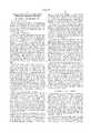
- FIG. 1is a perspective view of a preferred dialysis machine that includes an extracorporeal circuit module on which the integrity tests described herein are performed;
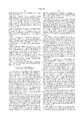
- FIG. 2is a schematic illustration of an extracorporeal circuit and dialysate preparation modules of the dialysis machine of FIG. 1, with components thereof that are not germane to the present invention omitted for the sake of clarity and brevity;
- FIG. 3is an elevational view of the extracorporeal circuit of FIG. 1, indicating that the arterial and venous lines may be connected to respective arterial and venous ports of a disinfection manifold, as they would be when the treatment session is ended and the tests described herein are performed;
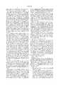
- FIG. 4is a simplified schematic diagram of the extracorporeal circuit of FIG. 2 and thermistors positioned downstream of the disinfection manifold, showing the path of heated fluid that is used to test whether the arterial and venous lines have been correctly installed in the disinfection manifold ports;
- FIG. 5is simplified schematic diagram of the extracorporeal circuit of FIG. 2 and thermistors positioned downstream of the disinfection manifold, showing the path of heated fluid when the arterial and venous lines have been incorrectly installed in the disinfection manifold ports;
- FIG. 6is a simplified schematic diagram of the extracorporeal circuit of FIG. 2 showing the apparatus used for conducting a pressure test to determine whether the arterial and venous lines have been correctly connected to the disinfection manifold ports;
- FIG. 7is a schematic diagram of the extracorporeal circuit of FIG. 6 with the lines connected to the wrong ports in the disinfection manifold.
- FIG. 1is an illustration of a dialysis machine 10, having a user interface 12, which may be employed in practicing the invention.
- the dialysis machine 10 in the illustrated embodimentis suitable for use outside of a traditional dialysis clinic setting, such as the home, nursing home or self-care clinic environment, however the invention is not considered limited to such uses of a machine or the particular machine illustrated.
- the dialysis machine 10includes an extracorporeal circuit module 24 mounted above a lower cabinet 22.
- the extracorporeal circuitis housed behind a door 27 in an enclosure 26 mounted to a turntable 28.
- the turntable 28is moveably mounted to the top of the lower cabinet 22 such that the turntable 28, enclosure 26 and extracorporeal circuit module 24 are capable of rotation as a unit relative to the lower cabinet 22 about a vertical axis.
- the dialysis machine 10has a water treatment module 23 and a dialysate preparation module 25 contained within the lower compartment or cabinet 22.
- the water treatment module 23plays no part in the present invention, and is described in detail in the '344 patent to Kenley et al. Additionally, the manner in which the dialysate solutions are prepared in the dialysate preparation module 25 and circulated through a dialysate circuit to a dialyzer in the extracorporeal circuit in the enclosure 26 is not particularly important to this invention, and may be as described in the Kenley et al. '344 patent (a preferred embodiment), or otherwise.
- the details as to the user interface 12are also not particularly important insofar as the present invention is concerned, and may be as described in the patent application of Rodney S. Kenley et al., Ser. No. 08/800,405 filed Feb. 14, 1997 or as described in the above-referenced Grogan et al. patent, or otherwise.
- the user interfaceincludes a touch sensitive display screen 14 and a set of three hard keys 16, 18 and 20 that are pressed by the user to enter and change parameter values and information for the machine.
- the user interfaceis connected via a hinge 29 and arm 30 to the cabinet 26.
- the user interfacerotates about a tilt axis T and a vertical axis A so as to enable the user interface to be positioned at a location convenient for the patient.
- the user interface arm 30may also be mounted to the front corner 32 of the machine.
- FIG. 2is a schematic illustration of the extracorporeal circuit 24 and dialysate preparation system 25 of the machine 10 of FIG. 1.
- bloodis removed from the patient and introduced into the arterial line 42.
- the arterial line 42is threaded through an electrically operable arterial line pinch clamp AC.
- One or more pressure sensors PAare placed in the line 42 to measure blood and air pressure in the arterial line 42.
- the clamp ACis opened and the patient's arterial fistula needle is connected to the connector terminating the arterial line 42, blood is removed from the patient by operation of an occlusive blood pump 44. Blood is circulated to the blood compartment or blood side of a dialyzer 46.
- Blood-borne toxins and excess waterare removed from the blood through the membrane 45 of the dialyzer 46 into a dialysate compartment of dialyzer 46 and into a dialysate circuit 72.
- the bloodis returned to the patient via the venous line 40.
- a connector (not shown) terminating the venous lineconnects to a venous fistula needle inserted into the patient.
- the venous line 40is threaded through an electrically operable venous line pinch clamp VC.
- an air trap 50in the venous line 40.
- the blood level in the air trap 50can be adjusted by known and conventional methods, and in FIG. 2 air is pumped into or out of the air trap 50 via a pump 200 (FIG. 4) in line 52 to raise or lower the level in the air trap.
- a pump 200FIG. 4
- the dialyzer 46, arterial and venous lines 42 and 40, venous bubble trap 50, blood pump 44, clamps AC and VC and air trap vent line 52are located in the upper housing or enclosure 26 of FIG. 1, as shown in FIG. 3.
- the dialysate preparation module 25 of FIGS. 1 and 2includes a fifty liter dialysate tank 54 storing a batch quantity of dialysate solution, and a pump 56 for pumping the solution from the tank through a heater assembly 58, a sterile ultrafilter 60, and into a line 62 leading to the dialysate side of the dialyzer 46.
- An inlet valve 64, bypass valve 66 and first and second inlet and outlet three way valves 68 and 70are provided in the dialysate circuit 72.
- the dialysate circuit 72includes an inlet line 74 and an outlet line 76 from the dialyzer.
- the outlet line 76is connected via valve 70 to a dialysate outlet line 78 that leads to a manifold 80.
- Valves downstream of the manifold 80dictate whether the returning dialysate is directed to the tank 54 via line 82, or sent via line 84 to an ultrafiltration pump 86.
- the ultrafiltration pump 86operates to remove precise volumes of dialysate solution from the dialysate circuit 72 into an ultrafiltration tank 90 via line 88.
- the fluid removed from the patientis pumped by the ultrafiltration pump 86 from the dialysate circuit 72 into the ultrafiltration tank 90, enabling precise measurement of the volume of fluid removed from the patient.
- the disinfection manifold 100is shown schematically in FIG. 2.
- the arterial line port 102receives a patient connector terminating the arterial line 42 after the treatment session is ended.
- the venous line port 104receives a patient connector terminating the venous line 40.
- a preferred construction of the ports 102 and 104, as well as the preferred construction of the patient connectors that terminate the arterial and venous lines,are described in the Kenley et al. '344 patent, therefore a detailed discussion will be omitted. It will be appreciated that the invention can be practiced with other configurations of the ports and patient connectors.
- the disinfection manifold 100is built into the bulkhead inside of the extracorporeal circuit housing or enclosure 26 of FIG. 1, such that the arterial and venous ports 102 and 104 are conveniently exposed to the patient. See FIG. 3.
- fluid circuitryis provided to place the disinfection manifold ports 102 and 104 in fluid communication with a source of disinfection fluids (such as hot water).
- the arterial port 102is connected to a line 120 that leads to a thermistor 122 (or TA for Thermistor Arterial), the purpose of which is described below.
- the thermistor 122senses the temperature of fluid in line 120 and sends temperature readings to the computer control system for the machine.
- the thermistor 122is installed in a line connected to a three-way valve V20, as shown in FIG. 2.
- the normally closed port NC of valve V20When the normally closed port NC of valve V20 is open the line 115 allows fluid to pass from the manifold 132, through the thermistor 122 through the line 120 and into the arterial line 42.
- Fluid in line 114can be directed to drain by keeping valve V20 open and opening a valve V14, sending fluid into a drain line 140 when valve V7 is closed.
- the venous disinfection manifold port 104is also connected to the dialysate preparation module 25 via a line 106, venous thermistor 108, and line 114.
- the line 114connects to a tee junction.
- One portion of the tee junctionconnects to a three-way valve V21 leading to the tank 54.
- the other portion of the teeconnects to a valve V14 which leads either to drain or to a valve V7 and the line between the heater 58 and the ultrafilter 60.
- valves V20, V14 and V21When valves V20, V14 and V21 are closed, the arterial line and venous line are isolated from the rest of the fluid circuitry in the dialysate preparation system. When valves V14, V21 are closed, the NO port of valve V20 allows fluid to recirculate between the lines 106 and 120. Valve V20, V14 and V21 also control the ability of fluid to be introduced into the extracorporeal circuit from the dialysate preparation system and also withdrawn from the extracorporeal circuit and directed to suitable structures or fluid networks, including the dialysate tank 54, the UF tank, or drain.
- FIG. 3is an elevational view of the extracorporeal circuit of FIG. 1, showing the arterial and venous lines 42 and 40, respectively, and how they connect to their respective arterial and venous ports 102 and 104 of the disinfection manifold 100, as they would be when the tests described herein are performed.
- the extracorporeal circuit integrity testsare preferably performed as a series of discrete tests. While they may be performed in any order, it has been found advantageous to perform them in the following order: 1) a dialyzer filter integrity test, 2) a blood tubing set integrity test, and 3) a blood tubing set clamp integrity test.
- This last set of testsis preferably conducted immediately after the patient reconnects the arterial and venous lines to the extracorporeal circuit disinfection manifold ports, and before the other three tests, although it too could be formed in a different sequence. For example, this last test could be conducted with the extracorporeal tubing set is replaced.
- the patienthas reconnected the arterial 42 and venous lines 40 to the disinfection manifold ports 102 and 104 of the disinfection manifold 100.
- the disinfection cycle for the dialysate preparation module 25 and the extracorporeal circuit 24(such as a hot water disinfection cycle) has been performed.
- the extracorporeal circuit 24is filled with reverse osmosis (RO) filtered water.
- the dialysate circuit 25is at ambient pressure.
- the air pump 200(FIGS. 4 and 5) in the venous bubble trap vent line 52 is operated to pump air into the air trap line 52.
- the occlusive blood pump 44prevents RO water from flowing past the blood pump 44, therefore water in the extracorporeal circuit is pushed through the dialyzer membrane 45 into the dialysate circuit 72 (which is open to atmosphere) due to the pressure gradient at the dialyzer membrane 45.
- fluid from the dialyzercould be pumped by the blood pump 44 to drain via line 114.
- the venous line 40 upstream of the bubble trap 50is pressurized to 500 mm Hg with the air pump 200 in the bubble trap vent line 52.
- the pressureis allowed to stabilize.
- the tests described herein that are based on pressurization of the extracorporeal circuitpreferably include a pressure stabilization time to insure that the extracorporeal circuit is actually pressurized in a static state.
- a pressure readingis taken automatically with the pressure sensor in the air trap vent line (PBo), and the value is stored in a memory for the computer control system governing operation of the machine.
- PBoair trap vent line
- a predetermined dwell periode.g., 30 seconds
- a minimum time of 30 secondsis recommended for the dwell period, with any additional time used for pressure stabilization.
- PBopressure decay measured by PBo is greater than a predetermined limit (e.g., 25 mm Hg/30 sec), repeat steps 3-5. If the second test indicates pressure decay greater than the limit, replace the extracorporeal tubing set 40, 42 and dialyzer 46 or sound an alarm. If the second test does not indicate a pressure decay greater than the limit, the normal sequence of events are continued and the blood tubing set and dialyzer are not replaced.
- a predetermined limite.g. 25 mm Hg/30 sec
- a method for in situ testing the integrity of a blood tubing set for an extracorporeal circuitis provided immediately after test no. 1.
- this testtakes advantage of the disinfection manifold ports 102 and 104, which are connected to hydraulic circuitry in the machine by the valves V20, V14, V21 located on the other side of the disinfection manifold 100.
- the valves V20, V14, V21are closed, the tubing set 40, 42 is isolated from the rest of the hydraulic circuitry, allowing the extracorporeal circuit to pressurize.
- the arterial and venous lines 42 and 40are connected to the respective arterial and venous manifold ports 102 and 104.
- Fluid which may be present in the blood tubing setis evacuated, by means of opening said arterial and venous clamps AC and VC and introducing air into the arterial and venous lines 42 and 40 to push the fluid out of the extracorporeal circuit via the disinfection manifold ports 102 and 104.
- Airis forced into the blood tubing set (such as by operating the pump 200 in the line 52, see FIG. 4) so as to raise the pressure in the blood tubing set 40, 42 substantially above ambient atmospheric pressure.
- the pressure in the blood tubing setis measured with a pressure sensor, such as pressure sensor PBo in the line 52 (FIG. 2).
- the pressure decay in the blood tubing setis determined by making a second pressure measurement after a predetermined dwell period has elapsed, with the magnitude of the pressure decay indicative of the condition of the blood tubing set. For example, if the pressure remains substantially constant after the dwell period, the blood tubing set 40 and 42 and associated connections to hardware are deemed to be in a satisfactory condition. However, if the pressure decay is too great, the tubing set is deemed to have failed and the user is prompted to replace the entire blood tubing set and dialyzer.
- the arterial and venous manifold ports receiving the arterial and venous linesare installed in the dialysis machine such that they are in fluid communication with a dialysate preparation system. This is the case in the embodiment of FIG. 2.
- a dialysate preparation systemThis is the case in the embodiment of FIG. 2.
- the valves V14, V20, V21are closed, they isolate the ports 102 and 104 from the dialysate preparation system.
- the preferred designis such that when the valves are open they allow fluid to be directed into the extracorporeal circuit from the dialysate preparation system.
- Such fluidsmay include dialysate solution, water, or a disinfection fluid such as heated water or a heated citric acid solution.
- fluidmay be directed into the extracorporeal circuit through the dialyzer membrane using a pump such as dialysate pump 56 or ultrafiltation pump 86.
- the arterial and venous linesare still connected to their respective ports in the disinfection manifold 100.
- the portion of the blood tubing set from the air trap 50 (including the dialyzer 46) to the blood pump 44is pressurized to approximately 500 mm Hg..
- the portion of the blood tubing set from the air trap 50 (including the blood line clamps) to the blood pump 44has some water in the line.
- the venous clamp VCis closed (set to not allow flow through the venous line).
- valve V20With port NO of valve V20 open, V14 closed, and valve V21 open, the clamp AC in the arterial line 42 is opened, and the air pump in line 52 and blood pump 44 are run for a short duration to push any residual water from the arterial line 42 through the port 102 and into the dialysate circuit 72 and tank 54.
- the clamp VC in the venous line 40is opened and the air pump in line 52 is run to send any residual water in the venous line 40 to the dialysate circuit via valve V21.
- the computer control system that controls the pressurization of the blood tubing setstores information as to the particular commercial dialyzer that is being used, and a table relating commercial dialyzers with a maximum value of trans-membrane pressure (TMP) specified by the manufacturer for the dialyzer.
- TMPtrans-membrane pressure
- the information as to the dialyzer currently installed on the machinemay be input into the computer system via the user interface 12 by the user at the time the extracorporeal circuit is installed (i.e., when the machine is new) or at the time the dialyzer and blood tubing set are replaced.
- the computer control systemcauses the blood tubing set to be pressurized to a predetermined value associated with the particular dialyzer installed on the machine. This is because the test should be conducted at a pressure in the blood tubing set that is below this maximum TMP value for the particular dialyzer installed in the machine.
- the arterial and venous linesare still connected to the disinfection manifold 100.
- the entire blood tubing set 40, 42 and dialyzer 46(including the portion between the arterial clamp AC and the blood pump 44) are pressurized to approximately 500 mm Hg., unless test no. 2 failed.
- the blood line clamps VC and ACare open, thereby allowing fluid to pass through the clamps.
- the UF tankis vented to atmosphere.
- valve V21Vent the venous line 40 from the venous clamp VC past the disinfection manifold port 104 and to the dialysate tank 54, and therefore to atmosphere, by turning on valve V21 (valves venting the tank 54 and UF tank 90 are already open).
- step 5would not be performed, but rather the pressure would be continuously monitored to see if the pressure decay stabilizes above a predetermined threshold limit. For example, if the pressure drops from the initial pressure level (say, of 550 mm Hg) to 450 mm Hg, but remains constant at that pressure thereafter, and if it has previously been determined that maintenance of pressure at or above 400 mm Hg indicates that the clamps meet patient safety requirements, then the clamps will have been deemed to have passed the test. However, if the tubing set was pressurized to say 550 mm Hg and decayed to 380 mm Hg and stabilized there, then the clamps will have been deemed to have failed.
- the initial pressure levelsay, of 550 mm Hg
- the pressure stabilization level used for the testwill depend on many factors, such as the level of acceptable back pressure designed into the extracorporeal circuit, the type of clamp and tubing that are used in the extracorporeal circuit, and the level of clamp performance that the manufacturer is willing to tolerate as acceptable.
- the clamp testcan be done on the arterial and venous lines at the same time, or serially one after the other. Further, the test could be performed without having the connectors terminating the arterial and venous lines plugged into the disinfection manifold, as long as the portion of the blood lines on the patient side of the clamps is at a substantially different pressure from the portion on the blood pump and dialyzer side of the clamps. What is important is that the portion of the blood tubing set on one side of the clamp is pressurized relative to the other side of the clamp, and the pressure is monitored to determine the condition of the clamp. This is accomplished by either a pressure decay type of test or a pressure maintenance type of test as set forth above.
- This testprovides a method for verifying the proper connection of the arterial and venous lines 42 and 40 the arterial and venous manifold ports.
- the testis performed after the user has reconnected the arterial and venous lines 42 and 40 to the arterial and venous disinfection manifold ports. It can also be performed when a new tubing set is installed on the machine.
- the testmay be performed immediately after the above three tests have been performed, or earlier, such as immediately after the patient has reconnected the arterial and venous lines to the ports of the disinfection manifold at the end of a dialysis treatment.
- a preferred embodiment of the testincludes two separate procedures or sub-tests: (1) an air pressure test to verify that the connections between the arterial and venous lines to the ports have been made, and (2) a test with fluid to determine that the arterial and venous lines have been connected to their respective arterial and venous ports, and not the otherwise (i.e., the arterial line is incorrectly installed on the venous port).
- an air pressure testto verify that the connections between the arterial and venous lines to the ports have been made
- a test with fluidto determine that the arterial and venous lines have been connected to their respective arterial and venous ports, and not the otherwise (i.e., the arterial line is incorrectly installed on the venous port).
- the arterial and venous clamps AC and VCare in an open condition.
- valves V14, V21 and V20 downstream of the disinfection manifold ports 102 and 104are closed to isolate the arterial and venous lines 42 and 40.
- this testtakes advantage of a fluid detection device positioned downstream of at least one of the arterial or venous ports of the disinfection manifold.
- two thermistors TA (122) and TV (108)are placed in the fluid lines 120 and 106 behind the disinfection manifold ports 102 and 104.
- thermistor TAmay be dispensed with.
- the fluidis introduced into the venous line and the venous thermistor TV does not send a signal to the computer control system indicating the detection of the fluid, then it is assumed that the arterial and venous lines are not installed correctly. In this respect, the absence of a signal, a null signal from the venous thermistor TV, or a signal indicating ambient temperature when heated fluid is introduced into the venous line, all would indicate that the lines were installed incorrectly.
- a different type of fluid detection deviceis used (such as a conductivity or pressure sensor) only one such device need be used.
- the fluid used in this testis water.
- the wateris introduced into the venous line 40 by backfiltering heated water (e.g., water at 50 degrees C.) from the dialysate side of the dialyzer membrane 45 into the extracorporeal circuit 24.
- the blood pump 44is turned off, and its occlusive nature requires that the backfiltered heated water flow through the venous line 40.
- the thermistor TVdetects the 50 degrees C. fluid, and responsively sends a signal indicating the temperature of the fluid to the central computer control system for the machine.
- the computer control systemnow has confirmation that the arterial and venous lines are properly installed. This connection is illustrated in the simplified schematic diagram of FIG. 4. Any other convenient fluid such as dialysate solution, saline solution, or a cleaning solution could be used.
- the inventioncan be employed with other types of fluid sensing equipment, such as ultrasonic, conductivity, pressure, optical, or other types of sensing or detecting equipment.
- Thermistorsare used in the preferred embodiment because they are also used in other aspects of machine operation (such as monitoring the temperature of hot water during a hot water disinfection cycle). In a machine that uses a chemical disinfection system, then conductivity, optical, or chemical sensors could be used.
- FIG. 5is simplified schematic diagram of the extracorporeal circuit and thermistors TA and TV positioned downstream of the disinfection manifold 100, showing the path of heated fluid when the arterial and venous lines have been incorrectly installed in the disinfection manifold ports. If the thermistor TA registers the presence of the hot fluid introduced into the venous line 40, then the patient has installed the arterial and venous lines on the wrong ports. The central computer system prompts the user to interchange the connections of the arterial and venous lines 42 and 40 relative to the ports 102 and 104. If neither of the thermistors TA and TV detect the fluid, then other corrective action is taken, such as prompting the user to initiate a service call, install the arterial or venous line connectors to the ports, etc.
- FIGS. 6 and 7An alternative method of determining whether the arterial and venous line connectors are correctly installed on their respective arterial and venous ports of the disinfection manifold will be described in conjunction with FIGS. 6 and 7.
- This methodinvolves placing the extracorporeal circuit at a different pressure from the hydraulic circuit on the other side of the disinfection manifold, and then opening a valve on the other side of the disinfection manifold to see whether a change in pressure occurs in the correct side of the occlusive blood pump in the extracorporeal circuit. For example, if the valve downstream of the venous port is opened and the pressure sensor in the venous portion of the extracorporeal circuit detects a change in pressure, then the venous line is correctly installed on the disinfection manifold. Conversely, if the pressure change is not detected in the venous portion of the extracorporeal circuit, then the arterial and venous lines are installed on the wrong ports.
- the arterial and venous lines 42 and 40are shown connected to their respective arterial and venous ports 102 and 104.
- the valves 201 and 203 downstream of the arterial and venous ports in lines 120 and 106are closed, thereby isolating the extracorporeal circuit from the hydraulic circuitry on the other side of the valves 201 and 203.
- the blood pump 44is occlusive. Therefore, when the air pump 200 is operated to pressurize the extracorporeal circuit (or, equivalently, draw a vacuum in the extracorporeal circuit), the portion of the extracorporeal circuit downstream of the blood pump 44, including the dialyzer 46, air trap and venous line is pressurized to a desired pressure.
- the conduit linking valves 201 and 203is open, allowing the arterial line 42 up to the blood pump to also pressurize.
- the pressure sensor PBomeasures the pressure in the venous portion of the extracorporeal circuit.
- the pressure sensor PAMmeasures the pressurization of the arterial portion of the extracorporeal circuit.
- the line 205 linking valves 201 and 203is closed off, with the arterial and venous lines thereby isolated from each other and from the hydraulic circuitry on the other side of the valves 201 and 203.
- the valve 203is opened, releasing pressure in the line that is connected to the port 104 (venous line 40 in FIG. 6).
- pressure sensor PBoshould immediately detect the change of pressure.
- PBosends a signal to the computer control system that this pressure change occurred, the lines are determined to be correctly installed.
- the arterial line 42is also pressurized, and valve 201 remains closed, the pressure measured by PAM should not change. This provides a backup or redundant check that the lines are correctly installed.
- FIG. 7illustrates the situation in which the lines 40 and 42 are incorrectly installed on the wrong ports.
- valve 203When valve 203 is opened, the pressure change is detected in PAM, and not in PBo. This will result in an alarm signal being generated in the machine, or a display of a prompt to the user to check the blood tubing set connections.
- the pressure in the arterial and venous linesis different from the pressure in the lines on the other side of the valves 201 and 203. While in the above example, the pressure differential is generated by maintaining the lines connected to the dialysate circuit at substantially atmospheric pressure and using the pump 200 to create the pressure differential, it would also be possible to maintain the extracorporeal circuit at any given pressure (e.g., atmospheric), and create either higher or lower pressure in both of the lines on the other side of the valves 201 and 203.
- any given pressuree.g., atmospheric
- the pressure changewill be detected by the pressure sensors PBo or PAM.
- the pressure changeshould be detected in PBo to indicate that the lines are correctly installed.
Landscapes
- Health & Medical Sciences (AREA)
- Heart & Thoracic Surgery (AREA)
- Vascular Medicine (AREA)
- Life Sciences & Earth Sciences (AREA)
- General Health & Medical Sciences (AREA)
- Anesthesiology (AREA)
- Biomedical Technology (AREA)
- Hematology (AREA)
- Veterinary Medicine (AREA)
- Animal Behavior & Ethology (AREA)
- Engineering & Computer Science (AREA)
- Public Health (AREA)
- Urology & Nephrology (AREA)
- Cardiology (AREA)
- Emergency Medicine (AREA)
- External Artificial Organs (AREA)
- Examining Or Testing Airtightness (AREA)
Abstract
Description
Claims (34)
Priority Applications (7)
| Application Number | Priority Date | Filing Date | Title |
|---|---|---|---|
| US09/140,483US6044691A (en) | 1998-08-26 | 1998-08-26 | Blood tubing set integrity tests for extracorporeal circuits |
| AU14618/99AAU1461899A (en) | 1998-08-26 | 1998-11-17 | Blood tubing set integrity tests for extracorporeal circuits |
| DE69837395TDE69837395T2 (en) | 1998-08-26 | 1998-11-17 | Integrity check of a blood line set for extracorporeal line circuits |
| PCT/US1998/024500WO2000012991A1 (en) | 1998-08-26 | 1998-11-17 | Blood tubing set integrity tests for extracorporeal circuits |
| EP98958614AEP1025427B1 (en) | 1998-08-26 | 1998-11-17 | Blood tubing set integrity test for extracorporeal circuits |
| JP2000567928AJP3393861B2 (en) | 1998-08-26 | 1998-11-17 | Completeness test of blood tube system set for extracorporeal circuit |
| JP2002296987AJP3732820B2 (en) | 1998-08-26 | 2002-10-10 | Completeness test of blood tube system set for extracorporeal circuit |
Applications Claiming Priority (1)
| Application Number | Priority Date | Filing Date | Title |
|---|---|---|---|
| US09/140,483US6044691A (en) | 1998-08-26 | 1998-08-26 | Blood tubing set integrity tests for extracorporeal circuits |
Publications (1)
| Publication Number | Publication Date |
|---|---|
| US6044691Atrue US6044691A (en) | 2000-04-04 |
Family
ID=22491438
Family Applications (1)
| Application Number | Title | Priority Date | Filing Date |
|---|---|---|---|
| US09/140,483Expired - LifetimeUS6044691A (en) | 1998-08-26 | 1998-08-26 | Blood tubing set integrity tests for extracorporeal circuits |
Country Status (6)
| Country | Link |
|---|---|
| US (1) | US6044691A (en) |
| EP (1) | EP1025427B1 (en) |
| JP (2) | JP3393861B2 (en) |
| AU (1) | AU1461899A (en) |
| DE (1) | DE69837395T2 (en) |
| WO (1) | WO2000012991A1 (en) |
Cited By (107)
| Publication number | Priority date | Publication date | Assignee | Title |
|---|---|---|---|---|
| US6327895B1 (en)* | 1997-07-09 | 2001-12-11 | Gambro Lundia Ab | Method and arrangement for integrity-testing of a tube-set for use in a cycler for peritoneal dialysis |
| US20030126910A1 (en)* | 2002-01-04 | 2003-07-10 | Burbank Jeffrey H. | Method and apparatus for leak detection in blood circuits combining external fluid detection and air infiltration detection |
| US20030217976A1 (en)* | 2002-05-24 | 2003-11-27 | Bowman Joseph H. | Vented medical fluid tip protector |
| US6659973B2 (en)* | 2001-01-04 | 2003-12-09 | Transvivo, Inc. | Apparatus and method for in-vivo plasmapheresis using periodic backflush |
| US20040069709A1 (en)* | 2001-07-12 | 2004-04-15 | Brugger James M. | Fluid circuits, systems, and processes for extracorporeal blood processing |
| US20040243046A1 (en)* | 2001-07-07 | 2004-12-02 | Brugger James M. | Method and apparatus for leak detection in a fluid line |
| US20050126998A1 (en)* | 2003-10-28 | 2005-06-16 | Childers Robert W. | Priming, integrity and head height methods and apparatuses for medical fluid systems |
| US20050154345A1 (en)* | 2004-01-13 | 2005-07-14 | Anton Milleker | Fluid flow sensor, method and system |
| US20060089586A1 (en)* | 2004-10-22 | 2006-04-27 | Kaus Stanley B | Convertible extracorporeal blood perfusion systems |
| US20060106331A1 (en)* | 2001-01-04 | 2006-05-18 | Gorsuch Reynolds G | Apparatus and method for in-vivo plasmapheresis using periodic backflush containing anticoagulant |
| US20070038191A1 (en)* | 2003-01-15 | 2007-02-15 | Burbank Jeffrey H | Waste balancing for extracorporeal blood treatment systems |
| EP1395311B1 (en) | 2001-06-05 | 2008-01-02 | Gambro Lundia AB | Method for filling and washing a filter for a dialysis machine |
| US20080195060A1 (en)* | 2007-02-09 | 2008-08-14 | Baxter International Inc. | Optical access disconnection systems and methods |
| US20080195021A1 (en)* | 2007-02-09 | 2008-08-14 | Baxter International Inc. | Acoustic access disconnection systems and methods |
| US20080214979A1 (en)* | 2003-11-07 | 2008-09-04 | Nxstage Medical, Inc. | Methods and Apparatus For Leak Detection in Blood Processing Systems |
| US20080210606A1 (en)* | 2004-01-07 | 2008-09-04 | Jeffrey Burbank | Filtration System Preparation of Fluids for Medical Applications |
| US20080230450A1 (en)* | 2005-01-07 | 2008-09-25 | Burbank Jeffrey H | Filtration System for Preparation of Fluids for Medical Applications |
| US20090004053A1 (en)* | 2007-06-29 | 2009-01-01 | Kenley Rodney S | Devices, systems, and methods for cleaning, disinfecting, rinsing, and priming blood separation devices and associated fluid lines |
| US20090099498A1 (en)* | 2007-10-12 | 2009-04-16 | Deka Products Limited Partnership | Systems, Devices and Methods for Cardiopulmonary Treatment and Procedures |
| US20090182263A1 (en)* | 2006-04-07 | 2009-07-16 | Burbank Jeffrey H | Filtration system for preparation of fluids for medical applications |
| US20090211975A1 (en)* | 2003-01-07 | 2009-08-27 | Brugger James M | Batch Filtration System for Preparation of Sterile Fluid for Renal Replacement Therapy |
| US20100145248A1 (en)* | 2008-12-04 | 2010-06-10 | Therox, Inc. | System for enriching a bodily fluid with a gas having automated priming capabilities |
| US20100181235A1 (en)* | 2007-05-25 | 2010-07-22 | Gambro Lundia Ab | device for connecting to a liquid source |
| US20100234787A1 (en)* | 2007-11-06 | 2010-09-16 | Jms Co. | Hemodialysis apparatus |
| US20100252490A1 (en)* | 2008-09-12 | 2010-10-07 | Fulkerson Barry N | Modular Reservoir Assembly for a Hemodialysis and Hemofiltration System |
| USD632792S1 (en)* | 2007-06-15 | 2011-02-15 | Haemonetics Corporation | Blood processing device |
| US20110120227A1 (en)* | 2008-07-22 | 2011-05-26 | Josef Beden | Method for operating a pressure measuring unit, apparatus having at least one pressure measuring unit, device having such an apparatus, and use of a measuring chamber |
| US8114043B2 (en) | 2008-07-25 | 2012-02-14 | Baxter International Inc. | Electromagnetic induction access disconnect sensor |
| DE102010035498A1 (en)* | 2010-08-25 | 2012-03-01 | Fresenius Medical Care Deutschland Gmbh | Method for detecting leaks, system and medical treatment device |
| WO2010062698A3 (en)* | 2008-10-30 | 2012-04-05 | Fresenius Medical Care Holdings, Inc. | Modular, portable dialysis system |
| US8235931B2 (en) | 2003-01-15 | 2012-08-07 | Nxstage Medical, Inc. | Waste balancing for extracorporeal blood treatment systems |
| WO2012154910A1 (en)* | 2011-05-12 | 2012-11-15 | Fresenius Medical Care Holdings, Inc. | Medical tubing installation detection |
| US20120298581A1 (en)* | 2011-05-23 | 2012-11-29 | Fresenius Medical Care Deutschland Gmbh | Device and method for detecting an operating state of an extracorporeal blood treatment |
| US8529490B2 (en) | 2002-04-10 | 2013-09-10 | Baxter International Inc. | Systems and methods for dialysis access disconnection |
| US8597505B2 (en) | 2007-09-13 | 2013-12-03 | Fresenius Medical Care Holdings, Inc. | Portable dialysis machine |
| US8608658B2 (en) | 2002-01-04 | 2013-12-17 | Nxstage Medical, Inc. | Method and apparatus for machine error detection by combining multiple sensor inputs |
| US8708946B2 (en) | 2002-04-10 | 2014-04-29 | Baxter International Inc. | Access disconnection systems using conductive contacts |
| WO2014099779A1 (en)* | 2012-12-20 | 2014-06-26 | Gambro Renal Products, Inc. | Blood set component connection detection |
| US8771511B2 (en) | 2007-11-29 | 2014-07-08 | Fresenius Medical Care Holdings, Inc. | Disposable apparatus and kit for conducting dialysis |
| US8836519B2 (en) | 2011-05-12 | 2014-09-16 | Fresenius Medical Care Holdings, Inc. | Determining the absence or presence of fluid in a dialysis system |
| US8920356B2 (en) | 2002-04-10 | 2014-12-30 | Baxter International Inc. | Conductive polymer materials and applications thereof including monitoring and providing effective therapy |
| US9138536B2 (en) | 2008-04-01 | 2015-09-22 | Gambro Lundia Ab | Apparatus and a method for monitoring a vascular access |
| US9157786B2 (en) | 2012-12-24 | 2015-10-13 | Fresenius Medical Care Holdings, Inc. | Load suspension and weighing system for a dialysis machine reservoir |
| US9295772B2 (en) | 2007-11-29 | 2016-03-29 | Fresenius Medical Care Holdings, Inc. | Priming system and method for dialysis systems |
| US9308307B2 (en) | 2007-09-13 | 2016-04-12 | Fresenius Medical Care Holdings, Inc. | Manifold diaphragms |
| EP2883558A4 (en)* | 2012-08-09 | 2016-04-13 | Nikkiso Co Ltd | BLOOD PURIFICATION DEVICE AND CORRESPONDING PRIMING METHOD |
| US9328969B2 (en) | 2011-10-07 | 2016-05-03 | Outset Medical, Inc. | Heat exchange fluid purification for dialysis system |
| US9354640B2 (en) | 2013-11-11 | 2016-05-31 | Fresenius Medical Care Holdings, Inc. | Smart actuator for valve |
| US9352282B2 (en) | 2007-09-25 | 2016-05-31 | Fresenius Medical Care Holdings, Inc. | Manifolds for use in conducting dialysis |
| US9358331B2 (en) | 2007-09-13 | 2016-06-07 | Fresenius Medical Care Holdings, Inc. | Portable dialysis machine with improved reservoir heating system |
| US9360129B2 (en) | 2009-01-12 | 2016-06-07 | Fresenius Medical Care Holdings, Inc. | Valve system |
| US9402945B2 (en) | 2014-04-29 | 2016-08-02 | Outset Medical, Inc. | Dialysis system and methods |
| AU2014262300B2 (en)* | 2008-10-30 | 2016-09-29 | Fresenius Medical Care Holdings, Inc. | Modular, Portable Dialysis System |
| US9545469B2 (en) | 2009-12-05 | 2017-01-17 | Outset Medical, Inc. | Dialysis system with ultrafiltration control |
| US20170167997A1 (en)* | 2014-07-28 | 2017-06-15 | Haemonetics Corporation | System and Method for Detecting Fluid Type |
| US9717840B2 (en) | 2002-01-04 | 2017-08-01 | Nxstage Medical, Inc. | Method and apparatus for machine error detection by combining multiple sensor inputs |
| US9827360B2 (en) | 2014-09-17 | 2017-11-28 | B. Braun Avitum Ag | Dialysis machine |
| US10155082B2 (en) | 2002-04-10 | 2018-12-18 | Baxter International Inc. | Enhanced signal detection for access disconnection systems |
| US10189728B2 (en) | 2011-12-13 | 2019-01-29 | Nxstage Medical, Inc. | Fluid purification methods, devices, and systems |
| US10195336B2 (en) | 2013-11-11 | 2019-02-05 | Nikkiso Company Limited | Blood purification apparatus and priming method thereof |
| US10195326B2 (en) | 2016-03-08 | 2019-02-05 | Fresenius Medical Care Holdings, Inc. | Methods and systems for detecting an occlusion in a blood circuit of a dialysis system |
| US10300190B2 (en) | 2012-12-20 | 2019-05-28 | Gambro Lundia Ab | Target volume based diaphragm repositioning for pressure measurement apparatus |
| US10406273B2 (en) | 2014-09-12 | 2019-09-10 | Nikkiso Company Limited | Blood purification apparatus |
| US10441699B2 (en) | 2015-01-23 | 2019-10-15 | Nikkiso Company Limited | Blood purification apparatus |
| US10463778B2 (en) | 2007-02-09 | 2019-11-05 | Baxter International Inc. | Blood treatment machine having electrical heartbeat analysis |
| US10561778B2 (en) | 2017-03-02 | 2020-02-18 | Fresenius Medical Care Holdings, Inc. | Split reservoir bags and method of using split reservoir bags to improve the heating and generation of dialysate |
| US10610634B2 (en) | 2015-05-21 | 2020-04-07 | Nikkiso Company Limited | Blood purification apparatus |
| US10625007B2 (en) | 2015-06-24 | 2020-04-21 | Nikkiso Company Limited | Blood purification apparatus and blood purification system |
| US10786616B2 (en) | 2015-12-17 | 2020-09-29 | Fresnius Medical Care Holdings, Inc. | System and method for controlling venous air recovery in a portable dialysis system |
| WO2020212579A1 (en)* | 2019-04-18 | 2020-10-22 | Fresenius Medical Care Deutschland Gmbh | Blocking device for a tube clamp of a blood treatment device |
| US10987460B2 (en) | 2016-03-08 | 2021-04-27 | Fresenius Medical Care Holdings, Inc. | Methods and systems of generating rapidly varying pressure amplitudes in fluidic circuits in a dialysis treatment system |
| US20210170089A1 (en)* | 2015-06-05 | 2021-06-10 | Debiotech S.A. | Testing of a Medical Fluid Treatment System |
| US11033671B2 (en) | 2011-05-24 | 2021-06-15 | Deka Products Limited Partnership | Systems and methods for detecting vascular access disconnection |
| US11033670B2 (en) | 2010-07-07 | 2021-06-15 | Deka Products Limited Partnership | Medical treatment system and methods using a plurality of fluid lines |
| US11052181B2 (en) | 2007-02-27 | 2021-07-06 | Deka Products Limited Partnership | Cassette system integrated apparatus |
| US11110214B2 (en) | 2017-04-07 | 2021-09-07 | Fresenius Medical Care Holdings, Inc. | Methods and systems for measuring and heating dialysate |
| US11110212B2 (en) | 2007-02-27 | 2021-09-07 | Deka Products Limited Partnership | Blood circuit assembly for a hemodialysis system |
| US11123463B2 (en) | 2015-06-24 | 2021-09-21 | Nikkiso Company Limited | Blood purification apparatus |
| US11154646B2 (en) | 2007-02-27 | 2021-10-26 | Deka Products Limited Partnership | Hemodialysis systems and methods |
| US11273245B2 (en) | 2002-07-19 | 2022-03-15 | Baxter International Inc. | Dialysis system having a vented disposable dialysis fluid carrying member |
| US11278655B2 (en)* | 2016-01-25 | 2022-03-22 | Nikkiso Company Limited | Blood purification apparatus |
| US11311656B2 (en) | 2007-02-27 | 2022-04-26 | Deka Products Limited Partnership | Modular assembly for a portable hemodialysis system |
| US11413387B2 (en) | 2016-09-23 | 2022-08-16 | Nikkiso Company Limited | Blood purification apparatus |
| US11525798B2 (en) | 2012-12-21 | 2022-12-13 | Fresenius Medical Care Holdings, Inc. | Method and system of monitoring electrolyte levels and composition using capacitance or induction |
| US11529444B2 (en) | 2007-02-27 | 2022-12-20 | Deka Products Limited Partnership | Blood treatment systems and methods |
| US11534537B2 (en) | 2016-08-19 | 2022-12-27 | Outset Medical, Inc. | Peritoneal dialysis system and methods |
| US11568043B2 (en) | 2007-02-27 | 2023-01-31 | Deka Products Limited Partnership | Control systems and methods for blood or fluid handling medical devices |
| US11690942B2 (en) | 2016-09-12 | 2023-07-04 | Nikkiso Company Limited | Blood purification apparatus with a bypass line that bypasses an ultrafiltration pump |
| US11696978B2 (en) | 2008-01-23 | 2023-07-11 | Deka Products Limited Partnership | Medical treatment system and methods using a plurality of fluid lines |
| US11725645B2 (en) | 2006-04-14 | 2023-08-15 | Deka Products Limited Partnership | Automated control mechanisms and methods for controlling fluid flow in a hemodialysis apparatus |
| US11724013B2 (en) | 2010-06-07 | 2023-08-15 | Outset Medical, Inc. | Fluid purification system |
| US11752248B2 (en) | 2008-01-23 | 2023-09-12 | Deka Products Limited Partnership | Medical treatment system and methods using a plurality of fluid lines |
| EP3797805B1 (en) | 2019-09-27 | 2023-09-13 | B. Braun Avitum AG | Blood treatment device with automatic air removal |
| US11766554B2 (en) | 2012-05-24 | 2023-09-26 | Deka Products Limited Partnership | Flexible tubing occlusion assembly |
| US11833281B2 (en) | 2008-01-23 | 2023-12-05 | Deka Products Limited Partnership | Pump cassette and methods for use in medical treatment system using a plurality of fluid lines |
| US11885758B2 (en) | 2007-02-27 | 2024-01-30 | Deka Products Limited Partnership | Sensor apparatus systems, devices and methods |
| US11890403B2 (en) | 2011-05-24 | 2024-02-06 | Deka Products Limited Partnership | Hemodialysis system |
| CN118168731A (en)* | 2024-05-13 | 2024-06-11 | 上海韬睿生物科技有限公司 | Method, system and device for detecting tightness after pipeline installation |
| US12026271B2 (en) | 2014-05-27 | 2024-07-02 | Deka Products Limited Partnership | Control systems and methods for blood or fluid handling medical devices |
| US12171922B2 (en) | 2008-08-27 | 2024-12-24 | Deka Products Limited Partnership | Blood treatment systems and methods |
| US12194213B2 (en) | 2011-11-04 | 2025-01-14 | Deka Products Limited Partnership | Medical treatment system and methods using a plurality of fluid lines |
| US12201762B2 (en) | 2018-08-23 | 2025-01-21 | Outset Medical, Inc. | Dialysis system and methods |
| US12220507B2 (en) | 2011-05-24 | 2025-02-11 | Deka Products Limited Partnership | Blood treatment systems and methods |
| US12303631B2 (en) | 2011-11-04 | 2025-05-20 | Deka Products Limited Partnership | Medical treatment system and methods using a plurality of fluid lines |
| US12318528B2 (en) | 2020-10-30 | 2025-06-03 | Mozarc Medical Us Llc | Variable orifice fistula graft |
| US12390565B2 (en) | 2019-04-30 | 2025-08-19 | Outset Medical, Inc. | Dialysis systems and methods |
| US12390567B2 (en) | 2005-01-07 | 2025-08-19 | Nxstage Medical, Inc. | Filtration system for preparation of fluids for medical applications |
Families Citing this family (31)
| Publication number | Priority date | Publication date | Assignee | Title |
|---|---|---|---|---|
| US7169352B1 (en) | 1999-12-22 | 2007-01-30 | Gambro, Inc. | Extracorporeal blood processing methods and apparatus |
| DE60035474T2 (en) | 1999-12-22 | 2008-03-13 | Gambro Inc., Lakewood | Device for extracorporeal blood treatment |
| US7608053B2 (en) | 2000-01-10 | 2009-10-27 | Caridianbct, Inc. | Extracorporeal blood processing methods with return-flow alarm |
| WO2002086437A1 (en)* | 2001-03-02 | 2002-10-31 | Waters Investments Limited | Methods and apparatus for determining the presence or absence of a fluid leak |
| ITMI20020359A1 (en) | 2002-02-22 | 2003-08-22 | Gambro Lundia Ab | METHOD OF CONTROL OF THE OPERATION OF A FLOW INTERDICTION BODY AND A FLOW STOP DEVICE FOR AN EXTRA-BODY CIRCUIT |
| US7704454B1 (en) | 2003-10-08 | 2010-04-27 | Caridianbct, Inc. | Methods and devices for processing blood |
| US7092796B2 (en)* | 2003-11-14 | 2006-08-15 | Cardinal Health 303, Inc. | System and method for verifying connection of correct fluid supply to an infusion pump |
| US7092797B2 (en)* | 2004-05-25 | 2006-08-15 | Sherwood Services Ag | Flow monitoring system for a flow control apparatus |
| JP4607503B2 (en)* | 2004-07-05 | 2011-01-05 | テルモ株式会社 | Blood component collection device |
| JP4742549B2 (en)* | 2004-09-17 | 2011-08-10 | ニプロ株式会社 | Blood purification equipment |
| JP4681401B2 (en)* | 2005-09-08 | 2011-05-11 | テルモ株式会社 | Blood component collection device |
| DE102006012087B4 (en) | 2006-03-14 | 2008-10-02 | Fresenius Medical Care Deutschland Gmbh | Method for at least partially emptying an extracorporeal blood circulation and hemodialysis machine for use of the method |
| JP4984685B2 (en)* | 2006-06-30 | 2012-07-25 | 澁谷工業株式会社 | Dialysis machine cleaning method |
| WO2010027437A2 (en)* | 2007-02-27 | 2010-03-11 | Deka Products Limited Partnership | Blood treatment systems and methods |
| CN101678164B (en)* | 2007-05-04 | 2013-04-03 | 弗雷泽纽斯医疗保健德国有限公司 | Method and device for monitoring a blood treatment unit of an extra-corporeal blood treatment device |
| WO2008152810A1 (en)* | 2007-06-13 | 2008-12-18 | Kuraray Medical Inc. | Blood purification apparatus and method of confirming circuit continuity failure thereof |
| JP5193794B2 (en)* | 2008-10-21 | 2013-05-08 | 帝人株式会社 | Home dialysis support system |
| US8500994B2 (en)* | 2010-01-07 | 2013-08-06 | Fresenius Medical Care Holdings, Inc. | Dialysis systems and methods |
| EP2601985A4 (en)* | 2010-08-05 | 2015-10-07 | Nikkiso Co Ltd | BLOOD PURIFYING DEVICE, AND METHOD FOR FLUID LEAK INSPECTION IN SUCH A DEVICE |
| JP5621591B2 (en)* | 2010-12-29 | 2014-11-12 | ニプロ株式会社 | Blood purification apparatus and automatic priming method for blood circulation circuit thereof |
| EP2714130A1 (en)* | 2011-05-31 | 2014-04-09 | Gambro Lundia AB | Method and device for detecting configurations of extracorporeal blood circuit, apparatus comprising detecting device, and computer program for performing the method |
| JP5421445B2 (en)* | 2012-10-30 | 2014-02-19 | 帝人株式会社 | Home dialysis support system |
| US9533135B2 (en) | 2014-06-19 | 2017-01-03 | Fenwal, Inc. | Method for forming, opening and/or evaluating a connection site |
| JP6545485B2 (en) | 2015-03-10 | 2019-07-17 | 日機装株式会社 | Blood purification device |
| JP6437349B2 (en) | 2015-03-10 | 2018-12-12 | 日機装株式会社 | Blood purification equipment |
| DE102015016842A1 (en)* | 2015-12-23 | 2017-06-29 | Fresenius Medical Care Deutschland Gmbh | Method and device for checking a dialyzer for the presence of a leak |
| JP6117973B1 (en)* | 2016-05-20 | 2017-04-19 | 株式会社コバヤシ | MEDICAL PREPARATION DEVICE, SOLUTION LEAKAGE DETECTING KIT FROM MEDICAL ADMINISTRATION DEVICE, AND SOLUTION LEAKAGE DETECTING METHOD |
| US11083827B2 (en)* | 2016-10-03 | 2021-08-10 | Baxter International Inc. | Medical fluid therapy machine including servicing regime therefore |
| EP3476414A1 (en) | 2017-10-27 | 2019-05-01 | Gambro Lundia AB | Dialysis machine and method |
| CN113474019A (en)* | 2018-07-20 | 2021-10-01 | 费森尤斯医疗护理德国有限责任公司 | Central control type multi-patient dialysis treatment system and application thereof |
| CN114061853B (en)* | 2021-10-19 | 2024-04-26 | 重庆永仁心医疗器械有限公司 | Blood pump sealing test method |
Citations (9)
| Publication number | Priority date | Publication date | Assignee | Title |
|---|---|---|---|---|
| US4444597A (en)* | 1980-03-03 | 1984-04-24 | Norman Gortz | Automated cleaning method for dialyzers |
| US4449392A (en)* | 1981-05-02 | 1984-05-22 | Bruno Huschke | Device for testing filters, particularly sterile filters |
| US4526574A (en)* | 1983-05-23 | 1985-07-02 | Baxter Travenol Laboratories, Inc. | Differential occlusion sensing method and apparatus |
| DE3442744A1 (en)* | 1984-11-23 | 1986-06-05 | Fresenius AG, 6380 Bad Homburg | Dialyser having a unit for the re-use of haemodialysers |
| US4695385A (en)* | 1985-04-29 | 1987-09-22 | Colorado Medical, Inc. | Dialyzer reuse system |
| US4834888A (en)* | 1986-12-08 | 1989-05-30 | Fresenius Ag | Hemodialysis apparatus comprising a sterile filter |
| US5580460A (en)* | 1992-11-27 | 1996-12-03 | Fresenius Ag | Process for determining the operability of the structural components in the dialysis section of a dialyzer of a hemodialysis apparatus and apparatus for executing this process |
| US5591344A (en)* | 1995-02-13 | 1997-01-07 | Aksys, Ltd. | Hot water disinfection of dialysis machines, including the extracorporeal circuit thereof |
| US5624551A (en)* | 1993-04-28 | 1997-04-29 | Fresenius Ag | Hydraulic safety circuit for a hemodialysis apparatus |
Family Cites Families (1)
| Publication number | Priority date | Publication date | Assignee | Title |
|---|---|---|---|---|
| DE3923078C1 (en)* | 1989-07-13 | 1990-09-27 | Fresenius Ag, 6380 Bad Homburg, De |
- 1998
- 1998-08-26USUS09/140,483patent/US6044691A/ennot_activeExpired - Lifetime
- 1998-11-17JPJP2000567928Apatent/JP3393861B2/ennot_activeExpired - Lifetime
- 1998-11-17AUAU14618/99Apatent/AU1461899A/ennot_activeAbandoned
- 1998-11-17WOPCT/US1998/024500patent/WO2000012991A1/enactiveIP Right Grant
- 1998-11-17DEDE69837395Tpatent/DE69837395T2/ennot_activeExpired - Lifetime
- 1998-11-17EPEP98958614Apatent/EP1025427B1/ennot_activeExpired - Lifetime
- 2002
- 2002-10-10JPJP2002296987Apatent/JP3732820B2/ennot_activeExpired - Fee Related
Patent Citations (10)
| Publication number | Priority date | Publication date | Assignee | Title |
|---|---|---|---|---|
| US4444597A (en)* | 1980-03-03 | 1984-04-24 | Norman Gortz | Automated cleaning method for dialyzers |
| US4449392A (en)* | 1981-05-02 | 1984-05-22 | Bruno Huschke | Device for testing filters, particularly sterile filters |
| US4526574A (en)* | 1983-05-23 | 1985-07-02 | Baxter Travenol Laboratories, Inc. | Differential occlusion sensing method and apparatus |
| DE3442744A1 (en)* | 1984-11-23 | 1986-06-05 | Fresenius AG, 6380 Bad Homburg | Dialyser having a unit for the re-use of haemodialysers |
| US4695385A (en)* | 1985-04-29 | 1987-09-22 | Colorado Medical, Inc. | Dialyzer reuse system |
| US4834888A (en)* | 1986-12-08 | 1989-05-30 | Fresenius Ag | Hemodialysis apparatus comprising a sterile filter |
| US5580460A (en)* | 1992-11-27 | 1996-12-03 | Fresenius Ag | Process for determining the operability of the structural components in the dialysis section of a dialyzer of a hemodialysis apparatus and apparatus for executing this process |
| US5624551A (en)* | 1993-04-28 | 1997-04-29 | Fresenius Ag | Hydraulic safety circuit for a hemodialysis apparatus |
| US5591344A (en)* | 1995-02-13 | 1997-01-07 | Aksys, Ltd. | Hot water disinfection of dialysis machines, including the extracorporeal circuit thereof |
| US5674390A (en)* | 1995-02-13 | 1997-10-07 | Aksys, Ltd. | Dialysis machine with leakage detection |
Non-Patent Citations (2)
| Title |
|---|
| W. Gentles, et al., Programmable Machine for Dialyzer Reuse, Med. & Bio. Eng. & Comp., vol. 18, pp. 765 781 (1980).* |
| W. Gentles, et al., Programmable Machine for Dialyzer Reuse, Med. & Bio. Eng. & Comp., vol. 18, pp. 765-781 (1980). |
Cited By (236)
| Publication number | Priority date | Publication date | Assignee | Title |
|---|---|---|---|---|
| US6327895B1 (en)* | 1997-07-09 | 2001-12-11 | Gambro Lundia Ab | Method and arrangement for integrity-testing of a tube-set for use in a cycler for peritoneal dialysis |
| US6659973B2 (en)* | 2001-01-04 | 2003-12-09 | Transvivo, Inc. | Apparatus and method for in-vivo plasmapheresis using periodic backflush |
| US7476210B2 (en) | 2001-01-04 | 2009-01-13 | Transvivo Inc. | Apparatus and method for in-vivo plasmapheresis using periodic backflush containing anticoagulant |
| US20060106331A1 (en)* | 2001-01-04 | 2006-05-18 | Gorsuch Reynolds G | Apparatus and method for in-vivo plasmapheresis using periodic backflush containing anticoagulant |
| US20030236482A1 (en)* | 2001-01-04 | 2003-12-25 | Gorsuch Reynolds G. | Apparatus and method for in-vivo plasmapheresis using periodic backflush |
| US8070706B2 (en) | 2001-01-04 | 2011-12-06 | Transvivo, Inc. | Apparatus and method for in-vivo plasmapheresis using periodic backflush containing anticoagulant |
| US20090118660A1 (en)* | 2001-01-04 | 2009-05-07 | Transvivo Inc. | Apparatus and method for in-vivo plasmapheresis using periodic backlush containing anticoagulant |
| EP1395311B1 (en) | 2001-06-05 | 2008-01-02 | Gambro Lundia AB | Method for filling and washing a filter for a dialysis machine |
| EP1395311B2 (en)† | 2001-06-05 | 2017-03-15 | Gambro Lundia AB | Method for filling and washing a filter for a dialysis machine |
| US20040243046A1 (en)* | 2001-07-07 | 2004-12-02 | Brugger James M. | Method and apparatus for leak detection in a fluid line |
| US7087033B2 (en) | 2001-07-07 | 2006-08-08 | Nxstage Medical, Inc. | Method and apparatus for leak detection in a fluid line |
| US7419597B2 (en) | 2001-07-12 | 2008-09-02 | Nxstage Medical Inc. | Fluid, circuits, systems, and processes for extracorporeal blood processing |
| US20040069709A1 (en)* | 2001-07-12 | 2004-04-15 | Brugger James M. | Fluid circuits, systems, and processes for extracorporeal blood processing |
| US20070185430A1 (en)* | 2001-07-12 | 2007-08-09 | Nxstage Medical, Inc. | Fluid, circuits, systems, and processes for extracorporeal blood processing |
| US7214312B2 (en) | 2001-07-12 | 2007-05-08 | Nxstage Medical, Inc. | Fluid circuits, systems, and processes for extracorporeal blood processing |
| US8641615B2 (en) | 2002-01-04 | 2014-02-04 | Nxstage Medical, Inc. | Method and apparatus for machine error detection by combining multiple sensor inputs |
| US8608658B2 (en) | 2002-01-04 | 2013-12-17 | Nxstage Medical, Inc. | Method and apparatus for machine error detection by combining multiple sensor inputs |
| US20030126910A1 (en)* | 2002-01-04 | 2003-07-10 | Burbank Jeffrey H. | Method and apparatus for leak detection in blood circuits combining external fluid detection and air infiltration detection |
| US10213540B2 (en) | 2002-01-04 | 2019-02-26 | Nxstage Medical, Inc. | Method and apparatus for machine error detection by combining multiple sensor inputs |
| US7040142B2 (en) | 2002-01-04 | 2006-05-09 | Nxstage Medical, Inc. | Method and apparatus for leak detection in blood circuits combining external fluid detection and air infiltration detection |
| US9717840B2 (en) | 2002-01-04 | 2017-08-01 | Nxstage Medical, Inc. | Method and apparatus for machine error detection by combining multiple sensor inputs |
| US10994067B2 (en) | 2002-01-04 | 2021-05-04 | Nxstage Medical, Inc. | Method and apparatus for machine error detection by combining multiple sensor inputs |
| US8801646B2 (en) | 2002-04-10 | 2014-08-12 | Baxter International Inc. | Access disconnection systems with arterial and venous line conductive pathway |
| US8529490B2 (en) | 2002-04-10 | 2013-09-10 | Baxter International Inc. | Systems and methods for dialysis access disconnection |
| US10155082B2 (en) | 2002-04-10 | 2018-12-18 | Baxter International Inc. | Enhanced signal detection for access disconnection systems |
| US8920356B2 (en) | 2002-04-10 | 2014-12-30 | Baxter International Inc. | Conductive polymer materials and applications thereof including monitoring and providing effective therapy |
| US8708946B2 (en) | 2002-04-10 | 2014-04-29 | Baxter International Inc. | Access disconnection systems using conductive contacts |
| US6929751B2 (en)* | 2002-05-24 | 2005-08-16 | Baxter International Inc. | Vented medical fluid tip protector methods |
| US20050173344A1 (en)* | 2002-05-24 | 2005-08-11 | Bowman Joseph H.Jr. | Medical system including vented tip protector |
| US7083719B2 (en) | 2002-05-24 | 2006-08-01 | Baxter International Inc. | Medical system including vented tip protector |
| US20030217976A1 (en)* | 2002-05-24 | 2003-11-27 | Bowman Joseph H. | Vented medical fluid tip protector |
| US11273245B2 (en) | 2002-07-19 | 2022-03-15 | Baxter International Inc. | Dialysis system having a vented disposable dialysis fluid carrying member |
| US11446417B2 (en) | 2003-01-07 | 2022-09-20 | Nxstage Medical, Inc. | Filtration system for preparation of fluids for medical applications |
| US7976711B2 (en) | 2003-01-07 | 2011-07-12 | Nxstage Medical, Inc. | Batch filtration system for preparation of sterile fluid for renal replacement therapy |
| US8545428B2 (en) | 2003-01-07 | 2013-10-01 | Nxstage Medical, Inc. | Filtration system for preparation of fluids for medical applications |
| US9388059B2 (en) | 2003-01-07 | 2016-07-12 | Nxstage Medical, Inc. | Filtration system for preparation of fluids for medical applications |
| US7749393B2 (en) | 2003-01-07 | 2010-07-06 | Nxstage Medical, Inc. | Batch filtration system for preparation of sterile fluid for renal replacement therapy |
| US8460558B2 (en) | 2003-01-07 | 2013-06-11 | Nxstage Medical, Inc. | Batch filtration system for preparation of sterile fluid for renal replacement therapy |
| US20100228177A1 (en)* | 2003-01-07 | 2010-09-09 | Brugger James M | Batch filtration system for preparation of sterile fluid for renal replacement therapy |
| US8679348B2 (en) | 2003-01-07 | 2014-03-25 | Nxstage Medical, Inc. | Filtration system for preparation of fluids for medical applications |
| US10130746B2 (en) | 2003-01-07 | 2018-11-20 | Nxstage Medical, Inc. | Filtration system for preparation of fluids for medical applications |
| US10420871B2 (en) | 2003-01-07 | 2019-09-24 | Nxstage Medical, Inc. | Filtration system for preparation of fluids for medical applications |
| US20090211975A1 (en)* | 2003-01-07 | 2009-08-27 | Brugger James M | Batch Filtration System for Preparation of Sterile Fluid for Renal Replacement Therapy |
| US20110186521A1 (en)* | 2003-01-07 | 2011-08-04 | Nxstage Medical, Inc. | Filtration system for preparation of fluids for medical applications |
| US8202420B2 (en) | 2003-01-07 | 2012-06-19 | Nxstage Medical, Inc. | Batch filtration system for preparation of sterile fluid for renal replacement therapy |
| US8235931B2 (en) | 2003-01-15 | 2012-08-07 | Nxstage Medical, Inc. | Waste balancing for extracorporeal blood treatment systems |
| US20070038191A1 (en)* | 2003-01-15 | 2007-02-15 | Burbank Jeffrey H | Waste balancing for extracorporeal blood treatment systems |
| US7686778B2 (en) | 2003-01-15 | 2010-03-30 | Nxstage Medical, Inc. | Waste balancing for extracorporeal blood treatment systems |
| US10117986B2 (en) | 2003-10-28 | 2018-11-06 | Baxter International Inc. | Peritoneal dialysis machine |
| US7575564B2 (en)* | 2003-10-28 | 2009-08-18 | Baxter International Inc. | Priming, integrity and head height methods and apparatuses for medical fluid systems |
| US8070709B2 (en) | 2003-10-28 | 2011-12-06 | Baxter International Inc. | Peritoneal dialysis machine |
| US8900174B2 (en) | 2003-10-28 | 2014-12-02 | Baxter International Inc. | Peritoneal dialysis machine |
| US20050126998A1 (en)* | 2003-10-28 | 2005-06-16 | Childers Robert W. | Priming, integrity and head height methods and apparatuses for medical fluid systems |
| US20110218475A1 (en)* | 2003-11-07 | 2011-09-08 | Nxstage Medical, Inc. | Methods and Apparatus for Leak Detection in Blood Processing Systems |
| US20080214979A1 (en)* | 2003-11-07 | 2008-09-04 | Nxstage Medical, Inc. | Methods and Apparatus For Leak Detection in Blood Processing Systems |
| US8002727B2 (en) | 2003-11-07 | 2011-08-23 | Nxstage Medical, Inc. | Methods and apparatus for leak detection in blood processing systems |
| US8480608B2 (en) | 2003-11-07 | 2013-07-09 | Nxstage Medical, Inc. | Methods and apparatus for leak detection in blood processing systems |
| US9533088B2 (en) | 2003-11-07 | 2017-01-03 | Nxstage Medical, Inc. | Methods and apparatus for leak detection in blood processing systems |
| US20080210606A1 (en)* | 2004-01-07 | 2008-09-04 | Jeffrey Burbank | Filtration System Preparation of Fluids for Medical Applications |
| US7152469B2 (en) | 2004-01-13 | 2006-12-26 | Baxter International Inc. | Fluid flow sensor, method and system |
| US20050154345A1 (en)* | 2004-01-13 | 2005-07-14 | Anton Milleker | Fluid flow sensor, method and system |
| US20060089586A1 (en)* | 2004-10-22 | 2006-04-27 | Kaus Stanley B | Convertible extracorporeal blood perfusion systems |
| US11896750B2 (en) | 2005-01-07 | 2024-02-13 | Nxstage Medical, Inc. | Filtration system for preparation of fluids for medical applications |
| US10973969B2 (en) | 2005-01-07 | 2021-04-13 | Nxstage Medical, Inc. | Filtration system for preparation of fluids for medical applications |
| US12390567B2 (en) | 2005-01-07 | 2025-08-19 | Nxstage Medical, Inc. | Filtration system for preparation of fluids for medical applications |
| US9700663B2 (en) | 2005-01-07 | 2017-07-11 | Nxstage Medical, Inc. | Filtration system for preparation of fluids for medical applications |
| US20080230450A1 (en)* | 2005-01-07 | 2008-09-25 | Burbank Jeffrey H | Filtration System for Preparation of Fluids for Medical Applications |
| US8469331B2 (en) | 2006-04-07 | 2013-06-25 | Nxstage Medical, Inc. | Filtration system for preparation of fluids for medical applications |
| US20090182263A1 (en)* | 2006-04-07 | 2009-07-16 | Burbank Jeffrey H | Filtration system for preparation of fluids for medical applications |
| US9636444B2 (en) | 2006-04-07 | 2017-05-02 | Nxstage Medical, Inc. | Filtration system for preparation of fluids for medical applications |
| US10926016B2 (en) | 2006-04-07 | 2021-02-23 | Nxstage Medical, Inc. | Filtration system for preparation of fluids for medical applications |
| US11633527B2 (en) | 2006-04-07 | 2023-04-25 | Nxstage Medical, Inc. | Filtration system for preparation of fluids for medical applications |
| US12364795B2 (en) | 2006-04-07 | 2025-07-22 | Nxstage Medical, Inc. | Filtration system for preparation of fluids for medical applications |
| US11725645B2 (en) | 2006-04-14 | 2023-08-15 | Deka Products Limited Partnership | Automated control mechanisms and methods for controlling fluid flow in a hemodialysis apparatus |
| US11828279B2 (en) | 2006-04-14 | 2023-11-28 | Deka Products Limited Partnership | System for monitoring and controlling fluid flow in a hemodialysis apparatus |
| US9089654B2 (en) | 2007-02-09 | 2015-07-28 | Baxter International Inc. | Acoustic access disconnection systems and methods |
| US8376978B2 (en) | 2007-02-09 | 2013-02-19 | Baxter International Inc. | Optical access disconnection systems and methods |
| US9352078B2 (en) | 2007-02-09 | 2016-05-31 | Baxter International Inc. | Electrical heartbeat access disconnection systems |
| US8152751B2 (en) | 2007-02-09 | 2012-04-10 | Baxter International Inc. | Acoustic access disconnection systems and methods |
| US20080195021A1 (en)* | 2007-02-09 | 2008-08-14 | Baxter International Inc. | Acoustic access disconnection systems and methods |
| US8603020B2 (en) | 2007-02-09 | 2013-12-10 | Baxter International Inc. | Ultrasound access disconnection systems and methods |
| US8795217B2 (en) | 2007-02-09 | 2014-08-05 | Baxter International Inc. | Acoustic access disconnection systems and methods |
| US20080195060A1 (en)* | 2007-02-09 | 2008-08-14 | Baxter International Inc. | Optical access disconnection systems and methods |
| US9950105B2 (en) | 2007-02-09 | 2018-04-24 | Baxter International Inc. | Blood treatment and electrical blood leak detection device therefore |
| US10463778B2 (en) | 2007-02-09 | 2019-11-05 | Baxter International Inc. | Blood treatment machine having electrical heartbeat analysis |
| US9138528B2 (en) | 2007-02-09 | 2015-09-22 | Baxter International Inc. | Acoustic access disconnection systems and methods |
| US8920355B2 (en) | 2007-02-09 | 2014-12-30 | Baxter International Inc. | Acoustic access disconnection systems and methods |
| US11154646B2 (en) | 2007-02-27 | 2021-10-26 | Deka Products Limited Partnership | Hemodialysis systems and methods |
| US11311656B2 (en) | 2007-02-27 | 2022-04-26 | Deka Products Limited Partnership | Modular assembly for a portable hemodialysis system |
| US12064540B2 (en) | 2007-02-27 | 2024-08-20 | Deka Products Limited Partnership | Hemodialysis systems and methods |
| US11052181B2 (en) | 2007-02-27 | 2021-07-06 | Deka Products Limited Partnership | Cassette system integrated apparatus |
| US11724011B2 (en) | 2007-02-27 | 2023-08-15 | Deka Products Limited Partnership | Blood treatment systems and methods |
| US11110212B2 (en) | 2007-02-27 | 2021-09-07 | Deka Products Limited Partnership | Blood circuit assembly for a hemodialysis system |
| US11793915B2 (en) | 2007-02-27 | 2023-10-24 | Deka Products Limited Partnership | Hemodialysis systems and methods |
| US11568043B2 (en) | 2007-02-27 | 2023-01-31 | Deka Products Limited Partnership | Control systems and methods for blood or fluid handling medical devices |
| US12059516B2 (en) | 2007-02-27 | 2024-08-13 | Deka Products Limited Partnership | Blood circuit assembly for a hemodialysis system |
| US11752244B2 (en) | 2007-02-27 | 2023-09-12 | Deka Products Limited Partnership | Blood circuit assembly for a hemodialysis system |
| US11885758B2 (en) | 2007-02-27 | 2024-01-30 | Deka Products Limited Partnership | Sensor apparatus systems, devices and methods |
| US11666690B2 (en) | 2007-02-27 | 2023-06-06 | Deka Products Limited Partnership | Blood treatment systems and methods |
| US11529444B2 (en) | 2007-02-27 | 2022-12-20 | Deka Products Limited Partnership | Blood treatment systems and methods |
| US20100181235A1 (en)* | 2007-05-25 | 2010-07-22 | Gambro Lundia Ab | device for connecting to a liquid source |
| US8425767B2 (en) | 2007-05-25 | 2013-04-23 | Gambro Lundia Ab | Device for connecting to a liquid source |
| USD632792S1 (en)* | 2007-06-15 | 2011-02-15 | Haemonetics Corporation | Blood processing device |
| US20090004053A1 (en)* | 2007-06-29 | 2009-01-01 | Kenley Rodney S | Devices, systems, and methods for cleaning, disinfecting, rinsing, and priming blood separation devices and associated fluid lines |
| US10471186B2 (en) | 2007-06-29 | 2019-11-12 | Baxter International Inc. | Devices, systems, and methods for cleaning, disinfecting, rinsing, and priming blood separation devices and associated fluid lines |
| US9616162B2 (en) | 2007-06-29 | 2017-04-11 | Baxter International Inc. | Devices, systems, and methods for cleaning, disinfecting, rinsing, and priming blood separation devices and associated fluid lines |
| US8562908B2 (en) | 2007-06-29 | 2013-10-22 | Baxter International Inc. | Devices, systems, and methods for cleaning, disinfecting, rinsing, and priming blood separation devices and associated fluid lines |
| US10383993B2 (en) | 2007-09-13 | 2019-08-20 | Fresenius Medical Care Holdings, Inc. | Pump shoe for use in a pumping system of a dialysis machine |
| US9358331B2 (en) | 2007-09-13 | 2016-06-07 | Fresenius Medical Care Holdings, Inc. | Portable dialysis machine with improved reservoir heating system |
| US11318248B2 (en) | 2007-09-13 | 2022-05-03 | Fresenius Medical Care Holdings, Inc. | Methods for heating a reservoir unit in a dialysis system |
| US10596310B2 (en) | 2007-09-13 | 2020-03-24 | Fresenius Medical Care Holdings, Inc. | Portable dialysis machine |
| US8597505B2 (en) | 2007-09-13 | 2013-12-03 | Fresenius Medical Care Holdings, Inc. | Portable dialysis machine |
| US10857281B2 (en) | 2007-09-13 | 2020-12-08 | Fresenius Medical Care Holdings, Inc. | Disposable kits adapted for use in a dialysis machine |
| US10258731B2 (en) | 2007-09-13 | 2019-04-16 | Fresenius Medical Care Holdings, Inc. | Manifold diaphragms |
| US9308307B2 (en) | 2007-09-13 | 2016-04-12 | Fresenius Medical Care Holdings, Inc. | Manifold diaphragms |
| US11071811B2 (en) | 2007-09-13 | 2021-07-27 | Fresenius Medical Care Holdings, Inc. | Portable dialysis machine |
| US9517296B2 (en) | 2007-09-13 | 2016-12-13 | Fresenius Medical Care Holdings, Inc. | Portable dialysis machine |
| US10022673B2 (en) | 2007-09-25 | 2018-07-17 | Fresenius Medical Care Holdings, Inc. | Manifolds for use in conducting dialysis |
| US9352282B2 (en) | 2007-09-25 | 2016-05-31 | Fresenius Medical Care Holdings, Inc. | Manifolds for use in conducting dialysis |
| US11224841B2 (en) | 2007-09-25 | 2022-01-18 | Fresenius Medical Care Holdings, Inc. | Integrated disposable component system for use in dialysis systems |
| US8105265B2 (en)* | 2007-10-12 | 2012-01-31 | Deka Products Limited Partnership | Systems, devices and methods for cardiopulmonary treatment and procedures |
| US20090099498A1 (en)* | 2007-10-12 | 2009-04-16 | Deka Products Limited Partnership | Systems, Devices and Methods for Cardiopulmonary Treatment and Procedures |
| CN101848740B (en)* | 2007-11-06 | 2012-08-15 | 株式会社Jms | Hemodialysis device |
| US20100234787A1 (en)* | 2007-11-06 | 2010-09-16 | Jms Co. | Hemodialysis apparatus |
| US8771511B2 (en) | 2007-11-29 | 2014-07-08 | Fresenius Medical Care Holdings, Inc. | Disposable apparatus and kit for conducting dialysis |
| US11439738B2 (en) | 2007-11-29 | 2022-09-13 | Fresenius Medical Care Holdings, Inc. | Methods and Systems for fluid balancing in a dialysis system |
| US10034973B2 (en) | 2007-11-29 | 2018-07-31 | Fresenius Medical Care Holdings, Inc. | Disposable apparatus and kit for conducting dialysis |
| US9415152B2 (en) | 2007-11-29 | 2016-08-16 | Fresenius Medical Care Holdings, Inc. | Disposable apparatus and kit for conducting dialysis |
| US10758661B2 (en) | 2007-11-29 | 2020-09-01 | Fresenius Medical Care Holdings, Inc. | Disposable apparatus and kit for conducting dialysis |
| US10758662B2 (en) | 2007-11-29 | 2020-09-01 | Fresenius Medical Care Holdings, Inc. | Priming system and method for dialysis systems |
| US9295772B2 (en) | 2007-11-29 | 2016-03-29 | Fresenius Medical Care Holdings, Inc. | Priming system and method for dialysis systems |
| US11696978B2 (en) | 2008-01-23 | 2023-07-11 | Deka Products Limited Partnership | Medical treatment system and methods using a plurality of fluid lines |
| US11752248B2 (en) | 2008-01-23 | 2023-09-12 | Deka Products Limited Partnership | Medical treatment system and methods using a plurality of fluid lines |
| US11833281B2 (en) | 2008-01-23 | 2023-12-05 | Deka Products Limited Partnership | Pump cassette and methods for use in medical treatment system using a plurality of fluid lines |
| US9138536B2 (en) | 2008-04-01 | 2015-09-22 | Gambro Lundia Ab | Apparatus and a method for monitoring a vascular access |
| US20110120227A1 (en)* | 2008-07-22 | 2011-05-26 | Josef Beden | Method for operating a pressure measuring unit, apparatus having at least one pressure measuring unit, device having such an apparatus, and use of a measuring chamber |
| US8375797B2 (en)* | 2008-07-22 | 2013-02-19 | Fresenius Medical Care Deutschland Gmbh | Method for operating a pressure measuring unit, apparatus having at least one pressure measuring unit, device having such an apparatus, and use of a measuring chamber |
| US8632486B2 (en) | 2008-07-25 | 2014-01-21 | Baxter International Inc. | Electromagnetic induction access disconnect systems |
| US8114043B2 (en) | 2008-07-25 | 2012-02-14 | Baxter International Inc. | Electromagnetic induction access disconnect sensor |
| US12171922B2 (en) | 2008-08-27 | 2024-12-24 | Deka Products Limited Partnership | Blood treatment systems and methods |
| US9199022B2 (en)* | 2008-09-12 | 2015-12-01 | Fresenius Medical Care Holdings, Inc. | Modular reservoir assembly for a hemodialysis and hemofiltration system |
| US9759710B2 (en) | 2008-09-12 | 2017-09-12 | Fresenius Medical Care Holdings, Inc. | Modular reservoir assembly for a hemodialysis and hemofiltration system |
| US20100252490A1 (en)* | 2008-09-12 | 2010-10-07 | Fulkerson Barry N | Modular Reservoir Assembly for a Hemodialysis and Hemofiltration System |
| US10035103B2 (en)* | 2008-10-30 | 2018-07-31 | Fresenius Medical Care Holdings, Inc. | Modular, portable dialysis system |
| AU2014262300B2 (en)* | 2008-10-30 | 2016-09-29 | Fresenius Medical Care Holdings, Inc. | Modular, Portable Dialysis System |
| US10758868B2 (en) | 2008-10-30 | 2020-09-01 | Fresenius Medical Care Holdings, Inc. | Methods and systems for leak detection in a dialysis system |
| WO2010062698A3 (en)* | 2008-10-30 | 2012-04-05 | Fresenius Medical Care Holdings, Inc. | Modular, portable dialysis system |
| EA024555B1 (en)* | 2008-10-30 | 2016-09-30 | Фрезениус Медикал Кеа Холдингс, Инк. | Modular, portable dialysis system |
| US10670577B2 (en) | 2008-10-30 | 2020-06-02 | Fresenius Medical Care Holdings, Inc. | Modular reservoir assembly for a hemodialysis and hemofiltration system |
| CN105056324A (en)* | 2008-10-30 | 2015-11-18 | 弗雷塞尼斯医疗保健控股公司 | Modular, portable dialysis system |
| US11169137B2 (en)* | 2008-10-30 | 2021-11-09 | Fresenius Medical Care Holdings, Inc. | Modular reservoir assembly for a hemodialysis and hemofiltration system |
| CN102639201B (en)* | 2008-10-30 | 2015-07-08 | 弗雷塞尼斯医疗保健控股公司 | Modular Portable Dialysis System |
| AU2009320007B2 (en)* | 2008-10-30 | 2014-12-04 | Fresenius Medical Care Holdings, Inc. | Modular, portable dialysis system |
| EP2342003A4 (en)* | 2008-10-30 | 2015-02-25 | Fresenius Med Care Hldg Inc | MODULAR, PORTABLE DIALYSIS SYSTEM |
| US8246564B2 (en)* | 2008-12-04 | 2012-08-21 | Therox, Inc. | System for enriching a bodily fluid with a gas having automated priming capabilities |
| US20100145248A1 (en)* | 2008-12-04 | 2010-06-10 | Therox, Inc. | System for enriching a bodily fluid with a gas having automated priming capabilities |
| US9360129B2 (en) | 2009-01-12 | 2016-06-07 | Fresenius Medical Care Holdings, Inc. | Valve system |
| US10808861B2 (en) | 2009-01-12 | 2020-10-20 | Fresenius Medical Care Holdings, Inc. | Valve system |
| US10197180B2 (en) | 2009-01-12 | 2019-02-05 | Fresenius Medical Care Holdings, Inc. | Valve system |
| US9545469B2 (en) | 2009-12-05 | 2017-01-17 | Outset Medical, Inc. | Dialysis system with ultrafiltration control |
| US11724013B2 (en) | 2010-06-07 | 2023-08-15 | Outset Medical, Inc. | Fluid purification system |
| US11033670B2 (en) | 2010-07-07 | 2021-06-15 | Deka Products Limited Partnership | Medical treatment system and methods using a plurality of fluid lines |
| US11964086B2 (en) | 2010-07-07 | 2024-04-23 | Deka Products Limited Partnership | Medical treatment system and methods using a plurality of fluid lines |
| DE102010035498B4 (en)* | 2010-08-25 | 2012-08-02 | Fresenius Medical Care Deutschland Gmbh | Method for detecting leaks, system and medical treatment device |
| US20130174650A1 (en)* | 2010-08-25 | 2013-07-11 | Fresenius Medical Care Deutschland Gmbh | Method for detecting leaks, system and medical treating device |
| DE102010035498A1 (en)* | 2010-08-25 | 2012-03-01 | Fresenius Medical Care Deutschland Gmbh | Method for detecting leaks, system and medical treatment device |
| US8973424B2 (en)* | 2010-08-25 | 2015-03-10 | Fresenius Medical Care Deutschland Gmbh | Method for detecting leaks, system and medical treating device |
| JP2013536423A (en)* | 2010-08-25 | 2013-09-19 | フレゼニウス ムディカル カーレ ドイチェランド ゲーエムベーハー | Method, system and medical device for detecting leaks |
| WO2012154910A1 (en)* | 2011-05-12 | 2012-11-15 | Fresenius Medical Care Holdings, Inc. | Medical tubing installation detection |
| US8836519B2 (en) | 2011-05-12 | 2014-09-16 | Fresenius Medical Care Holdings, Inc. | Determining the absence or presence of fluid in a dialysis system |
| US10086125B2 (en) | 2011-05-12 | 2018-10-02 | Fresenius Medical Care Holdings, Inc. | Dialysis medical system with a portable control unit |
| US9585995B2 (en) | 2011-05-12 | 2017-03-07 | Fresenius Medical Care Holdings, Inc. | Dialysis medical system with a portable control unit |
| US9333286B2 (en) | 2011-05-12 | 2016-05-10 | Fresenius Medical Care Holdings, Inc. | Medical tubing installation detection |
| US9250216B2 (en) | 2011-05-12 | 2016-02-02 | Fresenius Medical Care Holdings, Inc. | Controlling an ultrasonic transmitter |
| US20120298581A1 (en)* | 2011-05-23 | 2012-11-29 | Fresenius Medical Care Deutschland Gmbh | Device and method for detecting an operating state of an extracorporeal blood treatment |
| US12220507B2 (en) | 2011-05-24 | 2025-02-11 | Deka Products Limited Partnership | Blood treatment systems and methods |
| US11033671B2 (en) | 2011-05-24 | 2021-06-15 | Deka Products Limited Partnership | Systems and methods for detecting vascular access disconnection |
| US12397097B2 (en) | 2011-05-24 | 2025-08-26 | Deka Products Limited Partnership | Systems and methods for detecting vascular access disconnection |
| US11890403B2 (en) | 2011-05-24 | 2024-02-06 | Deka Products Limited Partnership | Hemodialysis system |
| US9328969B2 (en) | 2011-10-07 | 2016-05-03 | Outset Medical, Inc. | Heat exchange fluid purification for dialysis system |
| US12194213B2 (en) | 2011-11-04 | 2025-01-14 | Deka Products Limited Partnership | Medical treatment system and methods using a plurality of fluid lines |
| US12303631B2 (en) | 2011-11-04 | 2025-05-20 | Deka Products Limited Partnership | Medical treatment system and methods using a plurality of fluid lines |
| US10189727B2 (en) | 2011-12-13 | 2019-01-29 | Nxstage Medical, Inc. | Fluid purification methods, devices, and systems |
| US10947135B2 (en) | 2011-12-13 | 2021-03-16 | Nxstage Medical, Inc. | Fluid purification methods, devices, and systems |
| US12180096B2 (en) | 2011-12-13 | 2024-12-31 | Nxstage Medical, Inc. | Fluid purification methods, devices, and systems |
| US10189728B2 (en) | 2011-12-13 | 2019-01-29 | Nxstage Medical, Inc. | Fluid purification methods, devices, and systems |
| US11766554B2 (en) | 2012-05-24 | 2023-09-26 | Deka Products Limited Partnership | Flexible tubing occlusion assembly |
| EP2883558A4 (en)* | 2012-08-09 | 2016-04-13 | Nikkiso Co Ltd | BLOOD PURIFICATION DEVICE AND CORRESPONDING PRIMING METHOD |
| US9872951B2 (en) | 2012-08-09 | 2018-01-23 | Nikkiso Company Limited | Blood purification apparatus and priming method for the same |
| US20150335809A1 (en)* | 2012-12-20 | 2015-11-26 | Gambro Lundia Ab | Blood set component connection detection |
| WO2014099779A1 (en)* | 2012-12-20 | 2014-06-26 | Gambro Renal Products, Inc. | Blood set component connection detection |
| CN104394899A (en)* | 2012-12-20 | 2015-03-04 | 甘布罗伦迪亚肾脏产品公司 | Blood kit components connection and detection |
| US9844620B2 (en)* | 2012-12-20 | 2017-12-19 | Gambro Lundia Ab | Blood set component connection detection |
| US10300190B2 (en) | 2012-12-20 | 2019-05-28 | Gambro Lundia Ab | Target volume based diaphragm repositioning for pressure measurement apparatus |
| US11525798B2 (en) | 2012-12-21 | 2022-12-13 | Fresenius Medical Care Holdings, Inc. | Method and system of monitoring electrolyte levels and composition using capacitance or induction |
| US10539450B2 (en) | 2012-12-24 | 2020-01-21 | Fresenius Medical Care Holdings, Inc. | Load suspension and weighing system for a dialysis machine reservoir |
| US9157786B2 (en) | 2012-12-24 | 2015-10-13 | Fresenius Medical Care Holdings, Inc. | Load suspension and weighing system for a dialysis machine reservoir |
| US11187572B2 (en) | 2012-12-24 | 2021-11-30 | Fresenius Medical Care Holdings, Inc. | Dialysis systems with a suspended reservoir |
| US10195336B2 (en) | 2013-11-11 | 2019-02-05 | Nikkiso Company Limited | Blood purification apparatus and priming method thereof |
| US10019020B2 (en) | 2013-11-11 | 2018-07-10 | Fresenius Medical Care Holdings, Inc. | Smart actuator for valve |
| US10817004B2 (en)* | 2013-11-11 | 2020-10-27 | Fresenius Medical Care Holdings, Inc. | Valve system with a pressure sensing displacement member |
| US9354640B2 (en) | 2013-11-11 | 2016-05-31 | Fresenius Medical Care Holdings, Inc. | Smart actuator for valve |
| US20190138037A1 (en)* | 2013-11-11 | 2019-05-09 | Fresenius Medical Care Holdings, Inc. | Smart Actuator For Valve |
| US11305040B2 (en) | 2014-04-29 | 2022-04-19 | Outset Medical, Inc. | Dialysis system and methods |
| US9579440B2 (en) | 2014-04-29 | 2017-02-28 | Outset Medical, Inc. | Dialysis system and methods |
| US9504777B2 (en) | 2014-04-29 | 2016-11-29 | Outset Medical, Inc. | Dialysis system and methods |
| US9402945B2 (en) | 2014-04-29 | 2016-08-02 | Outset Medical, Inc. | Dialysis system and methods |
| US12026271B2 (en) | 2014-05-27 | 2024-07-02 | Deka Products Limited Partnership | Control systems and methods for blood or fluid handling medical devices |
| US10837933B2 (en)* | 2014-07-28 | 2020-11-17 | Haemonetics Corporation | System and method for detecting fluid type |
| US20170167997A1 (en)* | 2014-07-28 | 2017-06-15 | Haemonetics Corporation | System and Method for Detecting Fluid Type |
| US10406273B2 (en) | 2014-09-12 | 2019-09-10 | Nikkiso Company Limited | Blood purification apparatus |
| US9827360B2 (en) | 2014-09-17 | 2017-11-28 | B. Braun Avitum Ag | Dialysis machine |
| US10441699B2 (en) | 2015-01-23 | 2019-10-15 | Nikkiso Company Limited | Blood purification apparatus |
| US10610634B2 (en) | 2015-05-21 | 2020-04-07 | Nikkiso Company Limited | Blood purification apparatus |
| US20210170089A1 (en)* | 2015-06-05 | 2021-06-10 | Debiotech S.A. | Testing of a Medical Fluid Treatment System |
| US11123463B2 (en) | 2015-06-24 | 2021-09-21 | Nikkiso Company Limited | Blood purification apparatus |
| US10625007B2 (en) | 2015-06-24 | 2020-04-21 | Nikkiso Company Limited | Blood purification apparatus and blood purification system |
| US12285554B2 (en) | 2015-12-17 | 2025-04-29 | Fresenius Medical Care Holdings, Inc. | System and method for performing a saline rinse back in a portable dialysis system |
| US10786616B2 (en) | 2015-12-17 | 2020-09-29 | Fresnius Medical Care Holdings, Inc. | System and method for controlling venous air recovery in a portable dialysis system |
| US11278655B2 (en)* | 2016-01-25 | 2022-03-22 | Nikkiso Company Limited | Blood purification apparatus |
| US10850017B2 (en) | 2016-03-08 | 2020-12-01 | Fresenius Medical Care Holdings, Inc. | Methods and systems for detecting an occlusion in a blood circuit of a dialysis system |
| US10195326B2 (en) | 2016-03-08 | 2019-02-05 | Fresenius Medical Care Holdings, Inc. | Methods and systems for detecting an occlusion in a blood circuit of a dialysis system |
| US10987460B2 (en) | 2016-03-08 | 2021-04-27 | Fresenius Medical Care Holdings, Inc. | Methods and systems of generating rapidly varying pressure amplitudes in fluidic circuits in a dialysis treatment system |
| US11534537B2 (en) | 2016-08-19 | 2022-12-27 | Outset Medical, Inc. | Peritoneal dialysis system and methods |
| US11951241B2 (en) | 2016-08-19 | 2024-04-09 | Outset Medical, Inc. | Peritoneal dialysis system and methods |
| US11690942B2 (en) | 2016-09-12 | 2023-07-04 | Nikkiso Company Limited | Blood purification apparatus with a bypass line that bypasses an ultrafiltration pump |
| US11413387B2 (en) | 2016-09-23 | 2022-08-16 | Nikkiso Company Limited | Blood purification apparatus |
| US10561778B2 (en) | 2017-03-02 | 2020-02-18 | Fresenius Medical Care Holdings, Inc. | Split reservoir bags and method of using split reservoir bags to improve the heating and generation of dialysate |
| US11110214B2 (en) | 2017-04-07 | 2021-09-07 | Fresenius Medical Care Holdings, Inc. | Methods and systems for measuring and heating dialysate |
| US12201762B2 (en) | 2018-08-23 | 2025-01-21 | Outset Medical, Inc. | Dialysis system and methods |
| WO2020212579A1 (en)* | 2019-04-18 | 2020-10-22 | Fresenius Medical Care Deutschland Gmbh | Blocking device for a tube clamp of a blood treatment device |
| US12390565B2 (en) | 2019-04-30 | 2025-08-19 | Outset Medical, Inc. | Dialysis systems and methods |
| US12201763B2 (en) | 2019-09-27 | 2025-01-21 | B. Braun Avitum Ag | Blood treatment device with automatic air removal |
| EP3797805B1 (en) | 2019-09-27 | 2023-09-13 | B. Braun Avitum AG | Blood treatment device with automatic air removal |
| US12318528B2 (en) | 2020-10-30 | 2025-06-03 | Mozarc Medical Us Llc | Variable orifice fistula graft |
| CN118168731A (en)* | 2024-05-13 | 2024-06-11 | 上海韬睿生物科技有限公司 | Method, system and device for detecting tightness after pipeline installation |
Also Published As
| Publication number | Publication date |
|---|---|
| JP3732820B2 (en) | 2006-01-11 |
| DE69837395T2 (en) | 2007-11-29 |
| AU1461899A (en) | 2000-03-21 |
| JP2003175101A (en) | 2003-06-24 |
| EP1025427A1 (en) | 2000-08-09 |
| JP2002523772A (en) | 2002-07-30 |
| DE69837395D1 (en) | 2007-05-03 |
| EP1025427B1 (en) | 2007-03-21 |
| WO2000012991A1 (en) | 2000-03-09 |
| JP3393861B2 (en) | 2003-04-07 |
| EP1025427A4 (en) | 2004-12-08 |
Similar Documents
| Publication | Publication Date | Title |
|---|---|---|
| US6044691A (en) | Blood tubing set integrity tests for extracorporeal circuits | |
| JP4101382B2 (en) | Blood processing equipment | |
| US5711883A (en) | Method for testing dialyzer integrity prior to use | |
| US7959593B2 (en) | Blood purification apparatus and method for evaluating connection conditions of needles | |
| CN102762237B (en) | Blood purification device | |
| AU2010338448B2 (en) | System and method for monitoring the presence of blood | |
| US5808181A (en) | Method for testing a filter in a dialysis system | |
| US5580460A (en) | Process for determining the operability of the structural components in the dialysis section of a dialyzer of a hemodialysis apparatus and apparatus for executing this process | |
| US7850856B2 (en) | Method and device for monitoring the supply of substitution fluid during an extracorporeal blood treatment | |
| US20020104800A1 (en) | Method and apparatus for a hemodiafiltration delivery module | |
| US8182691B2 (en) | Apparatus for extracorporeal blood treatment with a device for checking a sterile filter, and method of checking a sterile filter of an extracorporeal blood treatment apparatus | |
| JP2845585B2 (en) | Test method for hemodialysis membrane | |
| JPH11151294A (en) | Method and device for monitoring fluid supplementation pump | |
| US9119922B2 (en) | Apparatus and method for identifying a tubing system for an extracorporeal blood treatment device | |
| CN108697990B (en) | Method and device for checking the presence of a leak in a dialyzer | |
| JPH10258120A (en) | Automatically preparing device for blood dialysis | |
| CN111954547A (en) | Dialysis device for performing dialysis treatment | |
| JP2020099584A (en) | Hemodialysis apparatus and connection state detection method of replenishment liquid line | |
| CN114533993A (en) | Method and system for detecting airtightness of replacement liquid interface of hemodiafiltration equipment | |
| CN114917422B (en) | A hemodiafiltration device and a leakage detection method thereof | |
| CN115461099A (en) | Extracorporeal blood treatment apparatus | |
| MXPA98002396A (en) | Method to test the integrity of dialyzed before usa |
Legal Events
| Date | Code | Title | Description |
|---|---|---|---|
| AS | Assignment | Owner name:AKSYS, LTD., ILLINOIS Free format text:ASSIGNMENT OF ASSIGNORS INTEREST;ASSIGNORS:KENLEY, RODNEY S.;KAPADIA, SEEMA A.;SCHROEDER, CHRISTINE F.;AND OTHERS;REEL/FRAME:009589/0572;SIGNING DATES FROM 19980202 TO 19980519 | |
| STCF | Information on status: patent grant | Free format text:PATENTED CASE | |
| FEPP | Fee payment procedure | Free format text:PAYOR NUMBER ASSIGNED (ORIGINAL EVENT CODE: ASPN); ENTITY STATUS OF PATENT OWNER: LARGE ENTITY Free format text:PAYER NUMBER DE-ASSIGNED (ORIGINAL EVENT CODE: RMPN); ENTITY STATUS OF PATENT OWNER: LARGE ENTITY | |
| FPAY | Fee payment | Year of fee payment:4 | |
| AS | Assignment | Owner name:DURUS LIFE SCIENCES MASTER FUND, LTD., A CAYMEN IS Free format text:SECURITY AGREEMENT;ASSIGNOR:AKSYS, LTD., A DELAWARE CORPORATION;REEL/FRAME:017400/0777 Effective date:20060331 | |
| AS | Assignment | Owner name:HHD LLC, A DELAWARE LIMITED LIABILITY COMPANY, MAS Free format text:ASSIGNMENT OF ASSIGNORS INTEREST;ASSIGNOR:DURUS LIFE SCIENCES MASTER FUND, LTD., A CAYMEN ISLANDS EXEMPTED COMPANY;REEL/FRAME:019466/0732 Effective date:20070307 Owner name:DURUS LIFE SCIENCES MASTER FUND, LTD., A CAYMEN IS Free format text:ASSIGNMENT OF ASSIGNORS INTEREST;ASSIGNOR:AKSYS LTD., A DELAWARE CORPORATION;REEL/FRAME:019466/0711 Effective date:20070307 | |
| FPAY | Fee payment | Year of fee payment:8 | |
| FPAY | Fee payment | Year of fee payment:12 | |
| FEPP | Fee payment procedure | Free format text:PAT HOLDER NO LONGER CLAIMS SMALL ENTITY STATUS, ENTITY STATUS SET TO UNDISCOUNTED (ORIGINAL EVENT CODE: STOL); ENTITY STATUS OF PATENT OWNER: LARGE ENTITY | |
| SULP | Surcharge for late payment | ||
| AS | Assignment | Owner name:BAXTER INTERNATIONAL INC., ILLINOIS Free format text:ASSIGNMENT OF ASSIGNORS INTEREST;ASSIGNOR:BAXTER HEALTHCARE SA, SINGAPORE BRANCH;REEL/FRAME:036795/0953 Effective date:20150904 Owner name:BAXTER HEALTHCARE SA, SWITZERLAND Free format text:ASSIGNMENT OF ASSIGNORS INTEREST;ASSIGNOR:BAXTER HEALTHCARE SA, SINGAPORE BRANCH;REEL/FRAME:036795/0953 Effective date:20150904 | |
| AS | Assignment | Owner name:BAXTER HEALTHCARE SA, SINGAPORE BRANCH, ILLINOIS Free format text:ASSIGNMENT OF ASSIGNORS INTEREST;ASSIGNOR:HHD, LLC;REEL/FRAME:037171/0532 Effective date:20110616 |