US6044646A - Micro cilia array and use thereof - Google Patents
Micro cilia array and use thereofDownload PDFInfo
- Publication number
- US6044646A US6044646AUS09/113,079US11307998AUS6044646AUS 6044646 AUS6044646 AUS 6044646AUS 11307998 AUS11307998 AUS 11307998AUS 6044646 AUS6044646 AUS 6044646A
- Authority
- US
- United States
- Prior art keywords
- actuator
- ink
- jul
- nozzle
- thermal
- Prior art date
- Legal status (The legal status is an assumption and is not a legal conclusion. Google has not performed a legal analysis and makes no representation as to the accuracy of the status listed.)
- Expired - Fee Related
Links
- 210000004081ciliaAnatomy0.000titleclaimsdescription17
- 239000000463materialSubstances0.000claimsabstractdescription36
- 230000033001locomotionEffects0.000claimsdescription40
- 229920001343polytetrafluoroethylenePolymers0.000claimsdescription30
- 239000004810polytetrafluoroethyleneSubstances0.000claimsdescription30
- 239000004020conductorSubstances0.000claimsdescription12
- -1polytetrafluoroethylenePolymers0.000claimsdescription12
- 238000010438heat treatmentMethods0.000claimsdescription6
- 238000005452bendingMethods0.000claimsdescription5
- 230000009471actionEffects0.000claimsdescription4
- WYTGDNHDOZPMIW-RCBQFDQVSA-NalstonineNatural productsC1=CC2=C3C=CC=CC3=NC2=C2N1C[C@H]1[C@H](C)OC=C(C(=O)OC)[C@H]1C2WYTGDNHDOZPMIW-RCBQFDQVSA-N0.000claimsdescription4
- 238000000819phase cycleMethods0.000claimsdescription3
- 230000008602contractionEffects0.000claimsdescription2
- 238000004519manufacturing processMethods0.000abstractdescription90
- 238000003491arrayMethods0.000abstractdescription9
- 239000004065semiconductorSubstances0.000abstractdescription8
- 239000012811non-conductive materialSubstances0.000abstract1
- 239000000976inkSubstances0.000description258
- 238000000034methodMethods0.000description156
- 238000003672processing methodMethods0.000description60
- 238000010276constructionMethods0.000description30
- 230000007246mechanismEffects0.000description18
- RYGMFSIKBFXOCR-UHFFFAOYSA-NCopperChemical compound[Cu]RYGMFSIKBFXOCR-UHFFFAOYSA-N0.000description17
- 229910052802copperInorganic materials0.000description17
- 239000010949copperSubstances0.000description17
- 230000008901benefitEffects0.000description15
- 238000005516engineering processMethods0.000description15
- 230000008569processEffects0.000description15
- 230000009467reductionEffects0.000description13
- 230000035882stressEffects0.000description12
- 239000000758substrateSubstances0.000description12
- XLYOFNOQVPJJNP-UHFFFAOYSA-NwaterSubstancesOXLYOFNOQVPJJNP-UHFFFAOYSA-N0.000description12
- 239000000049pigmentSubstances0.000description11
- 238000007639printingMethods0.000description11
- 230000002441reversible effectEffects0.000description9
- 238000013461designMethods0.000description8
- 230000005684electric fieldEffects0.000description8
- 229920000642polymerPolymers0.000description8
- 238000012546transferMethods0.000description8
- LFQSCWFLJHTTHZ-UHFFFAOYSA-NEthanolChemical compoundCCOLFQSCWFLJHTTHZ-UHFFFAOYSA-N0.000description7
- 239000012943hotmeltSubstances0.000description7
- PXHVJJICTQNCMI-UHFFFAOYSA-NnickelSubstances[Ni]PXHVJJICTQNCMI-UHFFFAOYSA-N0.000description7
- 239000003921oilSubstances0.000description7
- 238000000926separation methodMethods0.000description7
- 239000004094surface-active agentSubstances0.000description7
- 235000009899Agrostemma githagoNutrition0.000description6
- XUIMIQQOPSSXEZ-UHFFFAOYSA-NSiliconChemical compound[Si]XUIMIQQOPSSXEZ-UHFFFAOYSA-N0.000description6
- 230000008859changeEffects0.000description6
- 238000000151depositionMethods0.000description6
- 238000001035dryingMethods0.000description6
- 239000000975dyeSubstances0.000description6
- 238000010304firingMethods0.000description6
- 239000000696magnetic materialSubstances0.000description6
- 229910001172neodymium magnetInorganic materials0.000description6
- 229910052710siliconInorganic materials0.000description6
- 239000010703siliconSubstances0.000description6
- 229910045601alloyInorganic materials0.000description5
- 239000000956alloySubstances0.000description5
- 230000003321amplificationEffects0.000description5
- 238000009835boilingMethods0.000description5
- 150000002576ketonesChemical class0.000description5
- 238000003199nucleic acid amplification methodMethods0.000description5
- 240000000254Agrostemma githagoSpecies0.000description4
- LRHPLDYGYMQRHN-UHFFFAOYSA-NN-ButanolChemical compoundCCCCOLRHPLDYGYMQRHN-UHFFFAOYSA-N0.000description4
- 230000015572biosynthetic processEffects0.000description4
- 230000008878couplingEffects0.000description4
- 238000010168coupling processMethods0.000description4
- 238000005859coupling reactionMethods0.000description4
- 230000008021depositionEffects0.000description4
- 230000005686electrostatic fieldEffects0.000description4
- 238000005530etchingMethods0.000description4
- 239000012530fluidSubstances0.000description4
- 239000011521glassSubstances0.000description4
- 238000007641inkjet printingMethods0.000description4
- 239000012528membraneSubstances0.000description4
- 238000001465metallisationMethods0.000description4
- 229910052759nickelInorganic materials0.000description4
- 239000002245particleSubstances0.000description4
- 238000012545processingMethods0.000description4
- 235000021251pulsesNutrition0.000description4
- 230000015556catabolic processEffects0.000description3
- 238000009826distributionMethods0.000description3
- 230000009977dual effectEffects0.000description3
- 230000000694effectsEffects0.000description3
- 229910052746lanthanumInorganic materials0.000description3
- FZLIPJUXYLNCLC-UHFFFAOYSA-Nlanthanum atomChemical compound[La]FZLIPJUXYLNCLC-UHFFFAOYSA-N0.000description3
- 229910000734martensiteInorganic materials0.000description3
- 239000011159matrix materialSubstances0.000description3
- 239000004530micro-emulsionSubstances0.000description3
- 230000001052transient effectEffects0.000description3
- QGZKDVFQNNGYKY-UHFFFAOYSA-NAmmoniaChemical compoundNQGZKDVFQNNGYKY-UHFFFAOYSA-N0.000description2
- 229910003321CoFeInorganic materials0.000description2
- XEEYBQQBJWHFJM-UHFFFAOYSA-NIronChemical compound[Fe]XEEYBQQBJWHFJM-UHFFFAOYSA-N0.000description2
- 229910001030Iron–nickel alloyInorganic materials0.000description2
- 229910001329Terfenol-DInorganic materials0.000description2
- 229910010380TiNiInorganic materials0.000description2
- RTAQQCXQSZGOHL-UHFFFAOYSA-NTitaniumChemical compound[Ti]RTAQQCXQSZGOHL-UHFFFAOYSA-N0.000description2
- 244000178320Vaccaria pyramidataSpecies0.000description2
- QJVKUMXDEUEQLH-UHFFFAOYSA-N[B].[Fe].[Nd]Chemical compound[B].[Fe].[Nd]QJVKUMXDEUEQLH-UHFFFAOYSA-N0.000description2
- 238000004630atomic force microscopyMethods0.000description2
- 230000003115biocidal effectEffects0.000description2
- 239000003139biocideSubstances0.000description2
- KPLQYGBQNPPQGA-UHFFFAOYSA-Ncobalt samariumChemical compound[Co].[Sm]KPLQYGBQNPPQGA-UHFFFAOYSA-N0.000description2
- 239000012141concentrateSubstances0.000description2
- 229920001940conductive polymerPolymers0.000description2
- 239000013078crystalSubstances0.000description2
- 238000005137deposition processMethods0.000description2
- 239000000428dustSubstances0.000description2
- 239000000835fiberSubstances0.000description2
- 238000007710freezingMethods0.000description2
- 239000003906humectantSubstances0.000description2
- 229910052751metalInorganic materials0.000description2
- 239000002184metalSubstances0.000description2
- 238000002715modification methodMethods0.000description2
- 238000012856packingMethods0.000description2
- 229910052761rare earth metalInorganic materials0.000description2
- 150000002910rare earth metalsChemical class0.000description2
- 229910000938samarium–cobalt magnetInorganic materials0.000description2
- 229910001285shape-memory alloyInorganic materials0.000description2
- 230000000638stimulationEffects0.000description2
- 230000001360synchronised effectEffects0.000description2
- 230000009466transformationEffects0.000description2
- 230000007704transitionEffects0.000description2
- 101150048848ART10 geneProteins0.000description1
- 241001164374CalyxSpecies0.000description1
- OKTJSMMVPCPJKN-UHFFFAOYSA-NCarbonChemical compound[C]OKTJSMMVPCPJKN-UHFFFAOYSA-N0.000description1
- 229910052692DysprosiumInorganic materials0.000description1
- 229910000640Fe alloyInorganic materials0.000description1
- CWYNVVGOOAEACU-UHFFFAOYSA-NFe2+Chemical compound[Fe+2]CWYNVVGOOAEACU-UHFFFAOYSA-N0.000description1
- 101001024566Homo sapiens Ecto-ADP-ribosyltransferase 4Proteins0.000description1
- 101001106523Homo sapiens Regulator of G-protein signaling 1Proteins0.000description1
- FYYHWMGAXLPEAU-UHFFFAOYSA-NMagnesiumChemical compound[Mg]FYYHWMGAXLPEAU-UHFFFAOYSA-N0.000description1
- 239000004642PolyimideSubstances0.000description1
- 102100022491RNA-binding protein NOB1Human genes0.000description1
- 102100021269Regulator of G-protein signaling 1Human genes0.000description1
- 238000003854Surface PrintMethods0.000description1
- 229910052771TerbiumInorganic materials0.000description1
- 229910001069Ti alloyInorganic materials0.000description1
- ATJFFYVFTNAWJD-UHFFFAOYSA-NTinChemical compound[Sn]ATJFFYVFTNAWJD-UHFFFAOYSA-N0.000description1
- 239000012190activatorSubstances0.000description1
- 239000000853adhesiveSubstances0.000description1
- 230000001070adhesive effectEffects0.000description1
- 229910052782aluminiumInorganic materials0.000description1
- XAGFODPZIPBFFR-UHFFFAOYSA-NaluminiumChemical compound[Al]XAGFODPZIPBFFR-UHFFFAOYSA-N0.000description1
- 229910021529ammoniaInorganic materials0.000description1
- 238000004458analytical methodMethods0.000description1
- 230000000903blocking effectEffects0.000description1
- 239000002041carbon nanotubeSubstances0.000description1
- 229910021393carbon nanotubeInorganic materials0.000description1
- 238000004140cleaningMethods0.000description1
- 239000003086colorantSubstances0.000description1
- 230000002860competitive effectEffects0.000description1
- 239000002322conducting polymerSubstances0.000description1
- 238000001816coolingMethods0.000description1
- 230000007797corrosionEffects0.000description1
- 238000005260corrosionMethods0.000description1
- 238000005536corrosion preventionMethods0.000description1
- 230000007423decreaseEffects0.000description1
- 238000011161developmentMethods0.000description1
- 238000002059diagnostic imagingMethods0.000description1
- 239000002019doping agentSubstances0.000description1
- KBQHZAAAGSGFKK-UHFFFAOYSA-Ndysprosium atomChemical compound[Dy]KBQHZAAAGSGFKK-UHFFFAOYSA-N0.000description1
- 229920001971elastomerPolymers0.000description1
- 230000005611electricityEffects0.000description1
- 238000009713electroplatingMethods0.000description1
- 230000008030eliminationEffects0.000description1
- 238000003379elimination reactionMethods0.000description1
- 239000000839emulsionSubstances0.000description1
- 238000001704evaporationMethods0.000description1
- 230000008020evaporationEffects0.000description1
- 239000002360explosiveSubstances0.000description1
- 239000004744fabricSubstances0.000description1
- 238000001914filtrationMethods0.000description1
- 230000004907fluxEffects0.000description1
- 230000008014freezingEffects0.000description1
- 230000017525heat dissipationEffects0.000description1
- 230000002209hydrophobic effectEffects0.000description1
- 238000003384imaging methodMethods0.000description1
- 230000006698inductionEffects0.000description1
- 239000007924injectionSubstances0.000description1
- 238000002347injectionMethods0.000description1
- 238000001746injection mouldingMethods0.000description1
- 238000009413insulationMethods0.000description1
- 239000012212insulatorSubstances0.000description1
- 230000010354integrationEffects0.000description1
- 229910052742ironInorganic materials0.000description1
- 238000001459lithographyMethods0.000description1
- 229910052749magnesiumInorganic materials0.000description1
- 239000011777magnesiumSubstances0.000description1
- 229910001004magnetic alloyInorganic materials0.000description1
- 230000008018meltingEffects0.000description1
- 238000002844meltingMethods0.000description1
- 230000005499meniscusEffects0.000description1
- 150000002739metalsChemical class0.000description1
- VNWKTOKETHGBQD-UHFFFAOYSA-NmethaneChemical compoundCVNWKTOKETHGBQD-UHFFFAOYSA-N0.000description1
- 230000004048modificationEffects0.000description1
- 238000012986modificationMethods0.000description1
- 239000002991molded plasticSubstances0.000description1
- 229910021421monocrystalline siliconInorganic materials0.000description1
- 238000000465mouldingMethods0.000description1
- 229910001000nickel titaniumInorganic materials0.000description1
- HLXZNVUGXRDIFK-UHFFFAOYSA-Nnickel titaniumChemical compound[Ti].[Ti].[Ti].[Ti].[Ti].[Ti].[Ti].[Ti].[Ti].[Ti].[Ti].[Ni].[Ni].[Ni].[Ni].[Ni].[Ni].[Ni].[Ni].[Ni].[Ni].[Ni].[Ni].[Ni].[Ni]HLXZNVUGXRDIFK-UHFFFAOYSA-N0.000description1
- 238000007645offset printingMethods0.000description1
- 230000010355oscillationEffects0.000description1
- 239000004033plasticSubstances0.000description1
- 229920003023plasticPolymers0.000description1
- 229920002492poly(sulfone)Polymers0.000description1
- 229910021420polycrystalline siliconInorganic materials0.000description1
- 229920001721polyimidePolymers0.000description1
- 229920005591polysiliconPolymers0.000description1
- 229920000123polythiophenePolymers0.000description1
- 238000012805post-processingMethods0.000description1
- 230000035485pulse pressureEffects0.000description1
- 230000004044responseEffects0.000description1
- 239000007787solidSubstances0.000description1
- 239000000243solutionSubstances0.000description1
- 239000002904solventSubstances0.000description1
- 239000012899standard injectionSubstances0.000description1
- 239000000126substanceSubstances0.000description1
- 239000000725suspensionSubstances0.000description1
- 229920003051synthetic elastomerPolymers0.000description1
- GZCRRIHWUXGPOV-UHFFFAOYSA-Nterbium atomChemical compound[Tb]GZCRRIHWUXGPOV-UHFFFAOYSA-N0.000description1
- 230000008646thermal stressEffects0.000description1
Images


Classifications
- B—PERFORMING OPERATIONS; TRANSPORTING
- B41—PRINTING; LINING MACHINES; TYPEWRITERS; STAMPS
- B41J—TYPEWRITERS; SELECTIVE PRINTING MECHANISMS, i.e. MECHANISMS PRINTING OTHERWISE THAN FROM A FORME; CORRECTION OF TYPOGRAPHICAL ERRORS
- B41J2/00—Typewriters or selective printing mechanisms characterised by the printing or marking process for which they are designed
- B41J2/005—Typewriters or selective printing mechanisms characterised by the printing or marking process for which they are designed characterised by bringing liquid or particles selectively into contact with a printing material
- B41J2/01—Ink jet
- B41J2/135—Nozzles
- B41J2/14—Structure thereof only for on-demand ink jet heads
- B41J2/14427—Structure of ink jet print heads with thermal bend detached actuators
- B—PERFORMING OPERATIONS; TRANSPORTING
- B41—PRINTING; LINING MACHINES; TYPEWRITERS; STAMPS
- B41J—TYPEWRITERS; SELECTIVE PRINTING MECHANISMS, i.e. MECHANISMS PRINTING OTHERWISE THAN FROM A FORME; CORRECTION OF TYPOGRAPHICAL ERRORS
- B41J2/00—Typewriters or selective printing mechanisms characterised by the printing or marking process for which they are designed
- B41J2/005—Typewriters or selective printing mechanisms characterised by the printing or marking process for which they are designed characterised by bringing liquid or particles selectively into contact with a printing material
- B41J2/01—Ink jet
- B41J2/135—Nozzles
- B41J2/16—Production of nozzles
- B41J2/1621—Manufacturing processes
- B41J2/1626—Manufacturing processes etching
- B41J2/1628—Manufacturing processes etching dry etching
- B—PERFORMING OPERATIONS; TRANSPORTING
- B41—PRINTING; LINING MACHINES; TYPEWRITERS; STAMPS
- B41J—TYPEWRITERS; SELECTIVE PRINTING MECHANISMS, i.e. MECHANISMS PRINTING OTHERWISE THAN FROM A FORME; CORRECTION OF TYPOGRAPHICAL ERRORS
- B41J2/00—Typewriters or selective printing mechanisms characterised by the printing or marking process for which they are designed
- B41J2/005—Typewriters or selective printing mechanisms characterised by the printing or marking process for which they are designed characterised by bringing liquid or particles selectively into contact with a printing material
- B41J2/01—Ink jet
- B41J2/135—Nozzles
- B41J2/16—Production of nozzles
- B41J2/1621—Manufacturing processes
- B41J2/1635—Manufacturing processes dividing the wafer into individual chips
- B—PERFORMING OPERATIONS; TRANSPORTING
- B41—PRINTING; LINING MACHINES; TYPEWRITERS; STAMPS
- B41J—TYPEWRITERS; SELECTIVE PRINTING MECHANISMS, i.e. MECHANISMS PRINTING OTHERWISE THAN FROM A FORME; CORRECTION OF TYPOGRAPHICAL ERRORS
- B41J2/00—Typewriters or selective printing mechanisms characterised by the printing or marking process for which they are designed
- B41J2/005—Typewriters or selective printing mechanisms characterised by the printing or marking process for which they are designed characterised by bringing liquid or particles selectively into contact with a printing material
- B41J2/01—Ink jet
- B41J2/135—Nozzles
- B41J2/16—Production of nozzles
- B41J2/1621—Manufacturing processes
- B41J2/1637—Manufacturing processes molding
- B41J2/1639—Manufacturing processes molding sacrificial molding
- B—PERFORMING OPERATIONS; TRANSPORTING
- B41—PRINTING; LINING MACHINES; TYPEWRITERS; STAMPS
- B41J—TYPEWRITERS; SELECTIVE PRINTING MECHANISMS, i.e. MECHANISMS PRINTING OTHERWISE THAN FROM A FORME; CORRECTION OF TYPOGRAPHICAL ERRORS
- B41J2/00—Typewriters or selective printing mechanisms characterised by the printing or marking process for which they are designed
- B41J2/005—Typewriters or selective printing mechanisms characterised by the printing or marking process for which they are designed characterised by bringing liquid or particles selectively into contact with a printing material
- B41J2/01—Ink jet
- B41J2/135—Nozzles
- B41J2/16—Production of nozzles
- B41J2/1648—Production of print heads with thermal bend detached actuators
- B—PERFORMING OPERATIONS; TRANSPORTING
- B41—PRINTING; LINING MACHINES; TYPEWRITERS; STAMPS
- B41J—TYPEWRITERS; SELECTIVE PRINTING MECHANISMS, i.e. MECHANISMS PRINTING OTHERWISE THAN FROM A FORME; CORRECTION OF TYPOGRAPHICAL ERRORS
- B41J2/00—Typewriters or selective printing mechanisms characterised by the printing or marking process for which they are designed
- B41J2/005—Typewriters or selective printing mechanisms characterised by the printing or marking process for which they are designed characterised by bringing liquid or particles selectively into contact with a printing material
- B41J2/01—Ink jet
- B41J2/17—Ink jet characterised by ink handling
- B41J2/175—Ink supply systems ; Circuit parts therefor
- B41J2/17596—Ink pumps, ink valves
Definitions
- the present inventionrelates to a thermal actuator device and, in particular, discloses details of a micro cilia array and use thereof.
- the present inventionfurther relates to actuator technology and particularly relates to a micro mechanical actuator having improved characteristics.
- Thermal actuatorsare well known. Further, the utilization and construction of thermal actuators in micro mechanics and Micro Electro Mechanical Systems (MEMS) is also known.
- MEMSMicro Electro Mechanical Systems
- a thermal actuatorcomprising an elongate member of heat expansible material adapted to be anchored at a proximal end and having a movable distal end, and a plurality of independently heatable resistive elements incorporated in the elongate member located and arranged such that when selected resistive elements are heated by the application of electric current, the distal end is provided with controlled movement in two mutually orthogonal directions due to controlled bending of said elongate member.
- said elongate memberis substantially rectangular in section having an upper and a lower surface, and wherein three said heatable resistive elements are provided extending in an elongate direction along said member, two of said three elements being located side by side adjacent one of said upper and lower surfaces, and the third of said three elements being located adjacent the other of said upper and lower surfaces, laterally aligned with one of said two elements.
- said three elementsare electrically connected to a common return line at their ends closest to the distal end of said member.
- the resistive elementsare formed from a conductive material having a low coefficient of thermal expansion and an actuation material having a high coefficient of thermal expansion, said resistive elements being configured such that, upon heating, said actuation material is able to expand substantially unhindered by the conductive material.
- the conductive materialundergoes a concertinaing action upon expansion and contraction, and is formed in a serpentine or helical form.
- the common linecomprises a plate like conductive material having a series of spaced apart slots arranged for allowing the desired degree of bending of the conductive material.
- the actuation materialis formed around the conductive material including the slots. The actuator is attached to a lower substrate and the series of resistive elements include two heater elements arranged on a lower portion of the actuation substrate and a single heater and the common line formed upon portion of the action substrate.
- the actuation materialcomprises substantially polytetrafluoroethylene.
- One end of the thermal actuationis surface treated so as to increase its coefficient of friction. Further, one end of the thermal actuator comprises only the actuation material.
- a cilia array of thermal actuatorscomprising one end that is driven so as to continuously engage a moveable load so as to push it in one direction only. Further, adjacent thermal actuators in the cilia array are grouped into different groups with each group being driven together in a different phase cycle from adjacent groups. Preferably the number of phases is four.
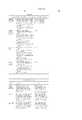
- FIG. 1is a perspective view of an arrangement of four single thermal actuators constructed in accordance with the preferred embodiment.
- FIG. 2is a close-up perspective view, partly in section, of a single thermal actuator constructed in accordance with the preferred embodiment.
- FIG. 3is a perspective view of a single thermal actuator constructed in accordance with the preferred embodiment, illustrating the thermal actuator being moved up and to a side.
- FIG. 4is an exploded perspective view illustrating the construction of a single thermal actuator in accordance with the preferred embodiment.
- FIG. 1there are illustrated 4 MEMS actuators 20, 21, 22, 23 as constructed in accordance with the preferred embodiment.
- FIG. 2there is illustrated a close-up perspective view, partly in section, of a single thermal actuator constructed in accordance with the preferred embodiment.
- Each actuator, e.g. 20,is based around three corrugated heat elements 11, 12 and 13 which are interconnected 14 to a cooler common current carrying line 16.
- the two heater elements 11, 12are formed on a bottom layer of the actuator 20 with the heater element 13 and common line 16 being formed on a top layer of the actuator 20.
- Each of the elements 11, 12, 13, 14 and 16can be formed from copper via means of deposition utilising semi-conductor fabrication techniques.
- the lines 11, 12, 13, 14 and 16are "encased" inside a polytetrafluoroethylene (PTFE) layer, e.g. 18 which has a high coefficient of thermal expansion.
- PTFEpolytetrafluoroethylene
- the PTFE layerhas a coefficient of thermal expansion which is much greater than that of the corresponding copper layers 12, 13, 14 and 16.
- the heater elements 11-13are therefore constructed in a serpentine manner so as to allow the concertinaing of the heater elements upon heating and cooling so as to allow for their expansion substantially with the expansion of the PTFE layer 18.
- the common line 16, also constructed from copperis provided with a series of slots, e.g. 19 which provide minimal concertinaing but allow the common layer 16 bend upwards and sideways when required.
- the actuatore.g. 20, can be operated in a number of different modes.
- the bottom two heater elements 11 and 12(FIG. 2) are activated. This causes the bottom portion of the polytetrafluoroethylene layer 18 (FIG. 2) to expand rapidly while the top portion of the polytetrafluoroethylene layer 18 (FIG. 2) remains cool.
- the resultant forcesare resolved by an upwards bending of the actuator 20 as illustrated in FIG. 1.
- the two heaters 12, 13are activated causing an expansion of the PTFE layer 18 (FIG. 2) on one side while the other side remains cool.
- the resulting expansionprovides for a movement of the actuator 20 to one side as illustrated in FIG. 1.
- FIG. 3there is provided a further form of movement this time being up and to a side.
- This form of movementis activated by heating each of the resistive elements 11-13 (FIG. 2) which is resolved a movement of the actuator 20 up and to the side.
- the position of the end point 30 of the actuator 20(FIG. 1) can be fully controlled.
- the PTFE portion 18is extended beyond the copper interconnect 14 so as to provide a generally useful end portion 30 for movement of objects to the like.
- FIG. 4there is illustrated an explosive perspective view of the construction of a single actuator.
- the actuatorcan be constructed utilising semi-conductor fabrication techniques and can be constructed on a wafer 42 or other form of substrate.
- a sacrificial etch layerto form an underside portion utilising a mask shape of a actuator device.
- a first layer of PTFE layer 64is deposited followed by the bottom level copper heater level 45 forming the bottom two heaters.
- a second copper layer 48is provided for the top heater and common line with interconnection 14 to the bottom copper layer.
- a further polytetrafluoroethylene layer of layer 44with the depositing of polytetrafluoroethylene layer 44 including the filling of the gaps, e.g. 49 in the return common line of the copper layer.
- the filling of the gapsallows for a significant reduction in the possibilities of laminar separation of the polytetrafluoroethylene layers from the copper layer.
- the two copper layersalso allow the routing of current drive lines to each actuator.
- an array of actuatorscould be formed on a single wafer and activated together so as to move an object placed near the array.
- Each actuator in the arraycan then be utilised to provide a circular motion of its end tip.
- the actuatorcan be in a rest position and then moved to a side position as illustrated for actuator 20 in FIG. 1 then moved to an elevated side position as illustrated in FIG. 3 thereby engaging the object to be moved.
- the actuatorcan then be moved to nearly an elevated position as shown for actuator 20 in FIG. 1. This resulting in a corresponding force being applied to the object to be moved.
- the actuatoris returned to its rest position and the cycle begins again.
- an objectcan be made to move in accordance with requirements.
- the reverse cyclecan be utilised to move an object in the opposite direction.
- an array of actuatorsare utilised thereby forming the equivalent of a cilia array of actuators.
- Multiple cilia arrayscan then be formed on a single semi-conductor wafer which is later diced into separate cilia arrays.
- the actuators on each cilia arrayare divided into groups with adjacent actuators being in different groups.
- the cilia arraycan then be driven in four phases with one in four actuators pushing the object to be moved in each portion of the phase cycle.
- the cilia arrayscan then be utilised to move an object, for example to move a card past an information sensing device in a controlled manner for reading information stored on the card.
- the cilia arrayscan be utilised to move printing media past a printing head in an ink jet printing device.
- the cilia arrayscan be utilised for manipulating means in the field of nano technology, for example in atomic force microscopy (AFM).
- AFMatomic force microscopy
- the PTFE end 20is preferably treated by means of an ammonia plasma etch so as to increase the coefficient of friction of the end portion.
- the embodiments of the inventionuse an ink jet printer type device. Of course many different devices could be used. However presently popular ink jet printing technologies are unlikely to be suitable.
- thermal inkjetThe most significant problem with thermal inkjet is power consumption. This is approximately 100 times that required for high speed, and stems from the energy-inefficient means of drop ejection. This involves the rapid boiling of water to produce a vapor bubble which expels the ink. Water has a very high heat capacity, and must be superheated in thermal inkjet applications. This leads to an efficiency of around 0.02%, from electricity input to drop momentum (and increased surface area) out.
- piezoelectric inkjetThe most significant problem with piezoelectric inkjet is size and cost. Piezoelectric crystals have a very small deflection at reasonable drive voltages, and therefore require a large area for each nozzle. Also, each piezoelectric actuator must be connected to its drive circuit on a separate substrate. This is not a significant problem at the current limit of around 300 nozzles per print head, but is a major impediment to the fabrication of pagewide print heads with 19,200 nozzles.
- the inkjet technologies usedmeet the stringent requirements of in-camera digital color printing and other high quality, high speed, low cost printing applications.
- new inkjet technologieshave been created.
- the target featuresinclude:
- inkjet designs shown hereare suitable for a wide range of digital printing systems, from battery powered one-time use digital cameras, through to desktop and network printers, and through to commercial printing systems.
- the print headis designed to be a monolithic 0.5 micron CMOS chip with MEMS post processing.
- the print headis 100 mm long, with a width which depends upon the inkjet type.
- the smallest print head designedis IJ38, which is 0.35 mm wide, giving a chip area of 35 square mm.
- the print headseach contain 19,200 nozzles plus data and control circuitry.
- Inkis supplied to the back of the print head by injection molded plastic ink channels.
- the moldingrequires 50 micron features, which can be created using a lithographically micromachined insert in a standard injection molding tool.
- Inkflows through holes etched through the wafer to the nozzle chambers fabricated on the front surface of the wafer.
- the print headis connected to the camera circuitry by tape automated bonding.
- inkjet configurationscan readily be derived from these 45 examples by substituting alternative configurations along one or more of the 11 axes.
- Most of the IJ01 to IJ45 examplescan be made into inkjet print heads with characteristics superior to any currently available inkjet technology.
- Suitable applicationsinclude: Home printers, Office network printers, Short run digital printers, Commercial print systems, Fabric printers, Pocket printers, Internet WWW printers, Video printers, Medical imaging, Wide format printers, Notebook PC printers, Fax machines, Industrial printing systems, Photocopiers, Photographic minilabs etc.
- the present applicationmay utilize advanced semiconductor fabrication techniques in the construction of large arrays of ink jet printers. Suitable manufacturing techniques are described in the following Australian provisional patent specifications incorporated here by cross-reference:
- the present applicationmay utilize an ink delivery system to the ink jet head.
- Delivery systems relating to the supply of ink to a series of ink jet nozzlesare described in the following Australian provisional patent specifications, the disclosure of which are hereby incorporated by cross-reference:
- the present applicationmay utilize advanced semiconductor microelectromechanical techniques in the construction of large arrays of ink jet printers. Suitable microelectromechanical techniques are described in the following Australian provisional patent specifications incorporated here by cross-reference:
- the present applicationmay include the utilization of a disposable camera system such as those described in the following Australian provisional patent specifications incorporated here by cross-reference:
- present applicationmay include the utilization of a data distribution system such as that described in the following Australian provisional patent specifications incorporated here by cross-reference:
- the present applicationmay include the utilization of camera and data processing techniques such as an Artcam type device as described in the following Australian provisional patent specifications incorporated here by cross-reference:
Landscapes
- Engineering & Computer Science (AREA)
- Manufacturing & Machinery (AREA)
- Particle Formation And Scattering Control In Inkjet Printers (AREA)
Abstract
Description
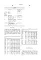
______________________________________ U.S. patent Docket application No. Ser. No. Title ______________________________________ IJ01US 09/112,751 Radiant Plunger Ink Jet Printer IJ02US 09/112,787 Electrostatic Ink Jet Printer IJ03US 09/112,802 Planar Thermoelastic Bend Actuator Ink Jet IJ04US 09/112,803 Stacked Electrostatic Ink Jet Printer IJ05US 09/113,097 Reverse Spring Lever Ink Jet Printer IJ06US 09/113,099 Paddle Type Ink Jet Printer IJ07US 09/113,084 Permanent Magnet Electromagnetic Ink Jet Printer IJ08US 09/113,066 Planar Swing Grill Electromagnetic Ink Jet Printer IJ09US 09/112,778 Pump Action Refill Ink Jet Printer IJ10US 09/112,779 Pulsed Magnetic Field Ink Jet Printer IJ11US 09/113,077 Two Plate Reverse Firing Electromagnetic Ink Jet Printer IJ12US 09/113,061 Linear Stepper Actuator Ink Jet Printer IJ13US 09/112,818 Gear Driven Shutter Ink Jet Printer IJ14US 09/112,816 Tapered Magnetic Pole Electromagnetic Ink Jet Printer IJ15US 09/112,772 Linear Spring Electromagnetic Grill Ink Jet Printer IJ16US 09/112,819 Lorenz Diaphragm Electromagnetic Ink Jet Printer IJ17US 09/112,815 PTFE Surface Shooting Shuttered Oscillating Pressure Ink Jet Printer IJ18US 09/113,096 Buckle Grip Oscillating Pressure Ink Jet Printer IJ19US 09/113,068 Shutter Based Ink Jet Printer IJ20US 09/113,095 Curling Calyx Thermoelastic Ink Jet Printer IJ21US 09/112,808 Thermal Actuated Ink Jet Printer IJ22US 09/112,809 Iris Motion Ink Jet Printer IJ23US 09/112,780 Direct Firing Thermal Bend Actuator Ink Jet Printer IJ24US 09/113,083 Conductive PTFE Ben Activator Vented Ink Jet Printer IJ25US 09/113,121 Magnetostrictive Ink Jet Printer IJ26US 09/113,122 Shape Memory Alloy Ink Jet Printer IJ27US 09/112,793 Buckle Plate Ink Jet Printer IJ28US 09/112,794 Thermal Elastic Rotary Impeller Ink Jet Printer IJ29US 09/113,128 Thermoelastic Bend Actuator Ink Jet Printer IJ30US 09/113,127 Thermoelastic Bend Actuator Using PTFE and Corrugated Copper Ink Jet Printer IJ31US 09/112,756 Bend Actuator Direct Ink Supply Ink Jet Printer IJ32US 09/112,755 A High Young's Modulus Thermoelastic Ink Jet Printer IJ33US 09/112,754 Thermally actuated slotted chamber wall ink jet printer IJ34US 09/112,811 Ink Jet Printer having a thermal actuator comprising an external coiled spring IJ35US 09/112,812 Trough Container Ink Jet Printer IJ36US 09/112,813 Dual Chamber Single Vertical Actuator Ink Jet IJ37US 09/112,814 Dual Nozzle Single Horizontal Fulcrum Actuator Ink Jet IJ38US 09/112,764 Dual Nozzle Single Horizontal Actuator Ink Jet IJ39US 09/112,765 A single bend actuator cupped paddle ink jet printing device IJ40US 09/112,767 A thermally actuated ink jet printer having a series of thermal actuator units IJ41US 09/112,768 A thermally actuated ink jet printer including a tapered heater element IJ42US 09/112,807 Radial Back-Curling Thermoelastic Ink Jet IJ43US 09/112,806 Inverted Radial Back-Curling Thermoelastic Ink Jet IJ44US 09/112,820 Surface bend actuator vented ink supply ink jet printer IJ45US 09/112,821 Coil Actuated Magnetic Plate Ink Jet Printer ______________________________________
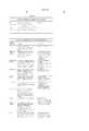
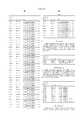
__________________________________________________________________________ACTUATOR MECHANISM (APPLIED ONLY TO SELECTED INK DROPS) __________________________________________________________________________Actuator Mechanism Description Advantages __________________________________________________________________________Thermal An electrothermal heater heats the ♦ Large force generated bubble ink to above boiling point, ♦ Simple construction transferring significant heat to the ♦ No moving parts aqueous ink. A bubble nucleates and ♦ Fast operation quickly forms, expelling the ink. ♦ Small chip area required for The efficiency of the process is low, actuator with typically less than 0.05% of the electrical energy being transformed into kinetic energy of the drop. Piezoelectric A piezoelectric crystal such as lead ♦ Low power consumption lanthanum zirconate (PZT) is ♦ Many ink types can be used electrically activated, and either ♦ Fast operation expands, shears, or bends to apply ♦ High efficiency pressure to the ink, ejecting drops. Electro- An electric field is used to activate ♦ Low power consumption strictive electrostriction in relaxor materials ♦ Many ink types can be used such as lead lanthanum zirconate ♦ Low thermal expansion titanate (PLZT) or lead magnesium ♦ Electric field strength niobate (PMN). required (approx. 3.5 V/μm) can be generated without difficulty ♦ Does not require electrical poling Ferroelectric An electric field is used to induce a ♦ Low power consumption phase transition between the ♦ Many ink types can be used antiferroelectric (AFE) and ♦ Fast operation (<1 μs) ferroelectric (FE) phase. Perovskite ♦ Relatively high longitudinal materials such as tin modified lead strain lanthanum zirconate titanate ♦ High efficiency (PLZSnT) exhibit large strains of up ♦ Electric field strength of to 1% associated with the AFE to FE around 3 V/μm can be phase transition. readily provided Electrostatic Conductive plates are separated by a ♦ Low power consumption plates compressible or fluid dielectric ♦ Many ink types can be used (usually air). Upon application of a ♦ Fast operation voltage, the plates attract each other and displace ink, causing drop ejection. The conductive plates may be in a comb or honeycomb structure, or stacked to increase the surface area and therefore the force. Electrostatic A strong electric field is applied to ♦ Low current consumption pull on ink the ink, whereupon electrostatic ♦ Low temperature attraction accelerates the ink towards the print medium. Permanent An electromagnet directly attracts a ♦ Low power consumption magnet permanent magnet, displacing ink ♦ Many ink types can be used electro- and causing drop ejection. Rare earth ♦ Fast operation magnetic magnets with a field strength around ♦ High efficiency. 1 Tesla can be used. Examples are: ♦ Easy extension from single Samarium Cobalt (SaCo) and nozzles to pagewidth print magnetic materials in the heads neodymium iron boron family (NdFeB, NdDyFeBNb, NdDyFeB, etc) Soft magnetic A solenoid induced a magnetic field ♦ Low power consumption core electro- in a soft magnetic core or yoke ♦ Many ink types can be used magnetic fabricated from a ferrous material ♦ Fast operation such as electroplated iron alloys such ♦ High efficiency as CoNiFe [1], CoFe, or NiFe alloys. ♦ Easy extension from single Typically, the soft magnetic material nozzles to pagewidth print is in two parts, which are normally heads held apart by a spring. When the solenoid is actuated, the two parts attract, displacing the ink. Magnetic The Lorenz force acting on a current ♦ Low power consumption Lorenz force carrying wire in a magnetic field is ♦ Many ink types can be used utilized. ♦ Fast operation This allows the magnetic field to be ♦ High efficiency supplied externally to the print head, ♦ Easy extension from single for example with rare earth nozzles to pagewidth print permanent magnets. heads Only the current carrying wire need be fabricated on the print-head, simplifying materials requirements. Magneto- The actuator uses the giant ♦ Many ink types can be used striction magnetostrictive effect of materiats ♦ Fast operation such as Terfenol-D (an alloy of ♦ Easy extension from single terbium, dysprosium and iron nozzles to pagewidth print developed at the Naval Ordnance heads Laboratory, hence Ter-Fe-NOL). For ♦ High force is available best efficiency, the actuator should be pre-stressed to approx. 8 MPa. Surface Ink under positive pressure is held in ♦ Low power consumption tension a nozzle by surface tension. The ♦ Simple construction reduction surface tension of the ink is reduced ♦ No unusual materials below the bubble threshold, causing required in fabrication the ink to egress from the nozzle. ♦ High efficiency ♦ Easy extension from single nozzles to pagewidth print heads Viscosity The ink viscosity is locally reduced ♦ Simple construction reduction to select which drops are to be ♦ No unusual materials ejected. A viscosity reduction can be required in fabrication achieved electrothermally with most ♦ Easy extension from single inks, but special inks can be nozzles to pagewidth print engineered for a 100:1 viscosity heads reduction. Acoustic An acoustic wave is generated and ♦ Can operate without a focussed upon the drop ejection nozzle plate region. Thermoelastic An actuator which relies upon ♦ Low power consumption bend actuator differential thermal expansion upon ♦ Many ink types can be used Joule heating is used. ♦ Simple planar fabrication ♦ Small chip area required for each actuator ♦ Fast operation ♦ High efficiency ♦ CMOS compatible voltages and currents ♦ Standard MEMS processes can be used ♦ Easy extension from single nozzles to pagewidth print heads High CTE A material with a very high ♦ High force can be generated thermoelastic coefficient of thermal expansion ♦ PTFE is a candidate for low actuator (CTE) such as dielectric constant polytetrafluoroethylene (PTFE) is insulation in ULSI used. As high CTE materials are ♦ Very low power usually non-conductive, a heater consumption fabricated from a conductive ♦ Many ink types can be used material is incorporated. A 50 μm ♦ Simple planar fabrication long PTFE bend actuator with ♦ Small chip area required for polysilicon heater and 15 mW power each actuator input can provide 180 μN force and ♦Fast operation 10 μm deflection. Actuator motions ♦ High efficiency include: ♦ CMOS compatible voltages 1) Bend and currents 2) Push ♦ Easy extension from single 3) Buckle nozzles to pagewidth print 4) Rotate heads Conductive A polymer with a high coefficient of ♦ High force can be generated polymer thermal expansion (such as PTFE) is ♦ Very low power thermoelastic doped with conducting substances to consumption actuator increase its conductivity to about 3 ♦ Many ink types can be used orders of magnitude below that of ♦ Simple planar fabrication copper. The conducting polymer ♦ Small chip area required for expands when resistively heated. each actuator Examples of conducting dopants ♦ Fast operation include: ♦ High efficiency 1) Carbon nanotubes ♦ CMOS compatible voltages 2) Metal fibers and currents 3) Conductive polymers such as ♦ Easy extension from single doped polythiophene nozzles to pagewidth print 4) Carbon granules heads Shape memory A shape memory alloy such as TiNi ♦ High force is available alloy (also known as Nitinol - Nickel (stresses of hundreds of Titanium alloy developed at the MPa) Naval Ordnance Laboratory) is ♦ Large strain is available thermally switched between its weak (more than 3%) martensitic state and its high ♦ High corrosion resistance stiffness austenic state. The shape of ♦ Simple construction the actuator in its martensitic state is ♦ Easy extension from single deformed relative to the austenic nozzles to pagewidth print shape. The shape change causes heads ejection of a drop. ♦ Low voltage operation Linear Linear magnetic actuators include ♦ Linear Magnetic actuators Magnetic the Linear Induction Actuator (LIA), can be constructed with Actuator Linear Permanent Magnet high thrust, long travel, and Synchronous Actuator (LPMSA), high efficiency using planar Linear Reluctance Synchronous semiconductor fabrication Actuator (LRSA), Linear Switched techniques Reluctance Actuator (LSRA), and ♦ Long actuator travel is the Linear Stepper Actuator (LSA). available ♦ Medium force is available ♦ Low voltage operation __________________________________________________________________________Actuator Mechanism Disadvantages Examples __________________________________________________________________________Thermal ♦ High power ♦ Canon Bubblejet bubble ♦ Ink carrier limited to water 1979 Endo et al GB ♦ Low efficiency patent 2,007,162 ♦ High temperatures required ♦ Xerox heater-in-pit ♦ High mechanical stress 1990 Hawkins et al ♦ Unusual materials required U.S. Pat. No. 4,899,181 ♦ Large drive transistors ♦ Hewlett-Packard TIJ ♦ Cavitation causes actuator failure 1982 Vaught et al ♦ Kogation reduces bubble formation U.S. Pat. No. 4,490,728 ♦ Large print heads are difficult to fabricate Piezoelectric ♦ Very large area required for actuator ♦ Kyser et al U.S. Pat. No. ♦ Difficult to integrate with electronics 3,946,398 ♦ High voltage drive transistors required ♦ Zoltan U.S. Pat. No. ♦ Full pagewidth print heads impractical 3,683,212 due to actuator size ♦ 1973 Stemme U.S. Pat. No. ♦ Requires electrical poling in high 3,747,120 strengths during manufacture ♦ Epson Stylus ♦ Tektronix ♦ IJ04 Electro- ♦ Low maximum strain (approx. 0.01%) ♦ Seiko Epson, Usui et strictive ♦ Large area required for actuator due all JP 253401/96 low strain ♦ IJ04 ♦ Response speed is marginal (˜10 μs) ♦ High voltage drive transistors required ♦ Full pagewidth print heads impractical due to actuator size Ferroelectric ♦ Difficult to integrate with electronics ♦ IJ04 ♦ Unusual materials such as PLZSnT are required ♦ Actuators require a large area Electrostatic ♦ Difficult to operate electrostatic ♦ IJ02, IJ04 plates devices in an aqueous environment ♦ The electrostatic actuator will normally need to be separated from the ink ♦ Very large area required to achieve high forces ♦ High voltage drive transistors may be required ♦ Full pagewidth print heads are not competitive due to actuator size Electrostatic ♦ High voltage required ♦ 1989 Saito et al, pull on ink ♦ May be damaged by sparks due to air U.S. Pat. No. 4,799,068 breakdown ♦ 1989 Miura et al, ♦ Required field strength increases as U.S. Pat. No. 4,810,954 drop size decreases ♦ Tone-jet ♦ High voltage drive transistors required ♦ Electrostatic field attracts dust Permanent ♦ Complex fabrication ♦ IJ07, IJ10 magnet ♦ Permanent magnetic material such as electro- Neodymium Iron Boron (NdFeB) magnetic required. ♦ High local currents required ♦ Copper metalization should be used for long electromigration lifetime and low resistivity ♦ Pigmented inks are usually infeasible ♦ Operating temperature limited to the Curie temperature (around 540 K) Soft magnetic ♦ Complex fabrication ♦ IJ01, IJ05, IJ08, IJ10 core electro- ♦ Materials not usually present in ♦ IJ12, IJ14, IJ15, IJ17 magnetic CMOS fab such as NiFe, CoNiFe, or CoFe are required ♦ High local currents required ♦ Copper metalization should be used for long electromigration lifetime and low resistivity ♦ Electroplating is required ♦ High saturation flux density is required (2.0-2.1 T is achievable with CoNiFe [1]) Magnetic ♦ Force acts as a twisting motion ♦ IJ06, IJ11, IJ13, IJ16 Lorenz force ♦ Typically, only a quarter of the solenoid length provides force in a useful direction ♦ High local currents required ♦ Copper metalization should be used for long electromigration lifetime and low reistivity ♦ Pigmented inks are usually infeasible Magneto- ♦ Force acts as a twisting motion ♦ Fischenbeck, U.S. Pat. No. striction ♦ Unusual materials such as Terfenol-D 4,032,929 are required ♦ IJ25 ♦ High local currents required ♦ Copper metalization should be used for long electromigration lifetime and low resistivity ♦ Pre-stressing may be required Surface ♦ Requires supplementary force to effect ♦ Silverbrook, EP 0771 tension drop separation 658 A2 and related reduction ♦ Requires special ink surfactants patent applications ♦ Speed may be limmited by surfactant properties Viscosity ♦ Requires supplementary force to effect ♦ Silverbrook, EP 0771 reduction drop separation 658 A2 and related ♦ Requires special ink viscosity patent applications properties ♦ High speed is difficult to achieve ♦ Requires oscillating ink pressure ♦ A high temperature difference (typically 80 degrees) is required Acoustic ♦ Complex drive circuitry ♦ 1993 Hadimioglu et ♦ Complex fabrication al, EUP 550,192 ♦ Low efficiency ♦ 1993 Elrod et al, EUP ♦ Poor control of drop position 572,220 ♦ Poor control of drop volume Thermoelastic ♦ Efficient aqueous operation requires ♦ IJ03, IJ09, IJ17, IJ18 bend actuator thermal insulator on the hot side ♦ IJ19, IJ20, IJ21, IJ22 ♦ Corrosion prevention can be difficult ♦ IJ23, IJ24, IJ27, IJ28 ♦ Pigmented inks may be infeasible, ♦ IJ29, IJ30, IJ31, IJ32 pigment particles may jam the bend ♦ IJ33, IJ34, IJ35, IJ36 actuator ♦ IJ37, IJ38, IJ39, IJ40 ♦ IJ41 High CTE ♦ Requires special material (e.g. PTFE) ♦ IJ09, IJ17, IJ18, IJ20 thermoelastic ♦ Requires a PTFE deposition process, ♦ IJ21, IJ22, IJ23, IJ24 actuator which is not yet standard in ULSI fabs ♦ IJ27, IJ28, IJ29, IJ30 ♦ PTFE deposition cannot be followed ♦ IJ31, IJ42, IJ43, IJ44 with high temperature (above 350° C.) processing ♦ Pigmented inks may be infeasible, as pigment particles may jam the bend actuator Conductive ♦ Requires special materials ♦ IJ24 polymer development (High CTE conductive thermoelastic polymer) actuator ♦ Requires a PTFE deposition process, which is not yet standard in ULSI fabs ♦ PTFE deposition cannot be followed with high temperature (above 350° C.) processing ♦ Evaporation and CVD deposition techniques cannot be used ♦ Pigmented inks may be infeasible, as pigment particles may jam the bend actuator Shape memory ♦ Fatigue limits maximum number of ♦ IJ26 alloy cycles ♦ Low strain (1%) is required to extend fatigue resistance ♦ Cycle rate limited by heat removal ♦ Requires unusual materials (TiNi) ♦ The latent heat of transformation must be provided ♦ High current operation ♦ Requires pre-stressing to distort the martensitic state Linear ♦ Requires unusual semiconductor ♦ IJ12 Magnetic materials such as soft magnetic alloys Actuator (e.g. CoNiFe [1]) ♦ Some varieties also require permanent magnetic materials such as Neodymium iron boron (NdFeB) ♦ Requires complex multi-phase drive circuitry ♦ High current operation __________________________________________________________________________
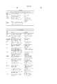
__________________________________________________________________________BASIC OPERATION MODE __________________________________________________________________________Operational mode Description Advantages __________________________________________________________________________Actuator This is the simplest mode of ♦ Simple operation directly operation: the actuator directly ♦ No external fields required pushes ink supplies sufficient kinetic energy to ♦ Satellite drops can be expel the drop. The drop must have a avoided if drop velocity is sufficient velocity to overcome the less than 4 m/s surface tension. ♦ Can be efficient, depending upon the actuator used Proximity The drops to be printed are selected ♦ Very simple print head by some manner (e.g. thermally fabrication can be used induced surface tension reduction of ♦ The drop selection means pressurized ink). Selected drops are does not need to provide the separated from the ink in the nozzle energy required to separate by contact with the print medium, or the drop from the nozzle a transfer roller. Electrostatic The drops to be printed are selected ♦ Very simple print head pull on ink by some manner (e.g. thermally fabrication can be used induced surface tension reduction of ♦ The drop selection means pressurized ink). Selected drops are does not need to provide the separated from the ink in the nozzle energy required to separate by a strong electric field. the drop from the nozzle Magnetic pull The drops to be printed are selected ♦ Very simple print head on ink by some manner (e.g. thermally fabrication can be used induced surface tension reduction of ♦ The drop selection means pressurized ink). Selected drops are does not need to provide the separated from the ink in the nozzle energy required to separate by a strong magnetic field acting on the drop from the nozzle the magnetic ink. Shutter The actuator moves a shutter to ♦ High speed (>50 KHz) block ink flow to the nozzle. The ink operation can be achieved pressure is pulsed at a multiple of the due to reduced refill time drop ejection frequency. ♦ Drop timing can be very accurate ♦ The actuator energy can be very low Shuttered grill The actuator moves a shutter to ♦ Actuators with small travel block ink flow through a grill to the can be used nozzle. The shutter movement need ♦ Actuators with small force only be equal to the width of the grill can be used holes. ♦ High speed (>50 KHz) operation can be achieved Pulsed A pulsed magnetic field attracts an ♦ Extremely low energy magnetic pull `ink pusher` at the drop ejection operation is possible on ink pusher frequency. An actuator controls a ♦ No heat dissipation catch, which prevents the ink pusher problems from moving when a drop is not to be ejected. __________________________________________________________________________Operational mode Disadvantages Examples __________________________________________________________________________Actuator ♦ Drop repetition rate is usually limited ♦ Thermal inkjet directly to less than 10 KHz. However, this is ♦ Piezoelectric inkjet pushes ink not fundamental to the method, but is ♦ IJ01, IJ02, IJ03, IJ04 related to the refill method normally ♦ IJ05, IJ06, IJ07, IJ09 used ♦ IJ11, IJ12, IJ14, IJ16 ♦ All of the drop kinetic energy must ♦ IJ20, IJ22, IJ23, IJ24 provided by the actuator ♦ IJ25, IJ26, IJ27, IJ28 ♦ Satellite drops usually form if drop ♦ IJ29, IJ30, IJ31, IJ32 velocity is greater than 4.5 m/s ♦ IJ33, IJ34, IJ35, IJ36 ♦ IJ37, IJ38, IJ39, IJ40 ♦ IJ41, IJ42, IJ43, IJ44 Proximity ♦ Requires close proximity between ♦ Silverbrook, EP 0771 print head and the print media or 658 A2 and related transfer roller patent applications ♦ May require two print heads printing alternate rows of the image ♦ Monolithic color print heads are difficult Electrostatic ♦ Requires very high electrostatic ♦ Silverbrook, EP 0771 pull on ink ♦ Electrostatic field for small nozzle 658 A2 and related sizes is above air breakdown patent applications ♦ Electrostatic field may attract dust ♦ Tone-Jet Magnetic pull ♦ Requires magnetic ink ♦ Silverbrook, EP 0771 on ink ♦ Ink colors other than black are difficult 658 A2 and related ♦ Requires very high magnetic fields patent applications Shutter ♦ Moving parts are required ♦ IJ13, IJ17, IJ21 ♦ Requires ink pressure modulator ♦ Friction and wear must be considered ♦ Stiction is possible Shuttered grill ♦ Moving parts are required ♦ IJ08, IJ15, IJ18, IJ19 ♦ Requires ink pressure modulator ♦ Friction and wear must be considered ♦ Stiction is possible Pulsed ♦ Requires an external pulsed magnetic ♦ IJ10 magnetic pull field on ink pusher ♦ Requires special materials for both the actuator and the ink pusher ♦ Complex construction __________________________________________________________________________
__________________________________________________________________________AUXILIARY MECHANISM (APPLIED TO ALL NOZZLES) __________________________________________________________________________Auxiliary Mechanism Description Advantages __________________________________________________________________________None The actuator directly fires the ink ♦ Simplicity of construction drop, and there is no external field or ♦ Simplicity of operation other mechanism required. ♦ Small physical size Oscillating ink The ink pressure oscillates, ♦ Oscillating ink pressure can pressure providing much of the drop ejection provide a refill pulse, (including energy. The actuator selects which allowing higher operating acoustic drops are to be fired by selectively speed stimulation) blocking or enabling nozzles. The ♦ The actuators may operate ink pressure oscillation may be with much lower energy achieved by vibrating the print head, ♦ Acoustic lenses can be used or preferably by an actuator in the to focus the sound on the ink supply. nozzles Media The print head is placed in close ♦ Low power proximity proximity to the print medium. ♦ High accuracy Selected drops protrude from the ♦ Simple print head print head further than unselected construction drops, and contact the print medium. The drop soaks into the medium fast enough to cause drop separation. Transfer roller Drops are printed to a transfer roller ♦ High accuracy instead of straight to the print ♦ Wide range of print medium. A transfer roller can also be substrates can be used used for proximity drop separation. ♦ Ink can be dried on the transfer roller Electrostatic An electric field is used to accelerate ♦ Low power selected drops towards the print ♦ Simple print head medium. construction Direct A magnetic field is used to accelerate ♦ Low power magnetic field selected drops of magnetic ink ♦ Simple print head towards the print medium. construction Cross The print head is placed in a constant ♦ Does not require magnetic magnetic field magnetic field. The Lorenz force in a materials to be integrated in current carrying wire is used to move the print head the actuator. manufacturing process Pulsed A pulsed magnetic field is used to ♦ Very low power operation magnetic field cyclically attract a paddle, which is possible pushes on the ink. A small actuator ♦ Small print head size moves a catch, which selectively prevents the paddle from moving. __________________________________________________________________________Auxiliary Mechanism Disadvantages Examples __________________________________________________________________________None ♦ Drop ejection energy must be supplied ♦ Most inkjets, by individual nozzle actuator including piezoelectric and thermal bubble. ♦ IJ01-IJ07, IJ09, IJ11 ♦ IJ12, IJ14, IJ20, IJ22 ♦ IJ23-IJ45 Oscillating ink ♦ Requires external ink pressure ♦ Silverbrook, EP 0771 pressure oscillator 658 A2 and related (including ♦ Ink pressure phase and amplitude patent applications acoustic be carefully controlled ♦ IJ08, IJ13, IJ15, IJ17 stimulation) ♦ Acoustic reflections in the ink chamber ♦ IJ18, IJ19, IJ21 must be designed for Media ♦ Precision assembly required ♦ Silverbrook, EP 0771 proximity ♦ Paper fibers may cause problems 658 A2 and related ♦ Cannot print on rough substrates patent applications Transfer roller ♦ Bulky ♦ Silverbrook, EP 0771 ♦ Expensive 658 A2 and related ♦ Complex construction patent applications ♦ Tektronix hot melt piezoelectric inkjet ♦ Any of the IJ series Electrostatic ♦ Field strength required for separation ♦ Silverbrook, EP 0771 of small drops is near or above air 658 A2 and related breakdown patent applications ♦ Tone-Jet Direct ♦ Requires magnetic ink ♦ Silverbrook, EP 0771 magnetic field ♦ Requires strong magnetic field 658 A2 and related patent applications. Cross ♦ Requires external magnet ♦ IJ06, IJ16 magnetic field ♦ Current densities may be high, resulting in electromigration problems Pulsed ♦ Complex print head construction ♦ IJ10 magnetic field ♦ Magnetic materials required in print head __________________________________________________________________________
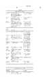
__________________________________________________________________________ACTUATOR AMPLIFICATION OR MODIFICATION METHOD __________________________________________________________________________Actuator amplification Description Advantages __________________________________________________________________________None No actuator mechanical ♦ Operational simplicity amplification is used. The actuator directly drives the drop ejection process. Differential An actuator material expands more ♦ Provides greater travel in a expansion on one side than on the other. The reduced print head area bend actuator expansion may be thermal, ♦ The bend actuator converts piezoelectric, magnetostrictive, or a high force low travel other mechanism. actuator mechanism to high travel, lower force mechanism. Transient bend A trilayer bend actuator where the ♦ Very good temperature actuator two outside layers are identical. This stability cancels bend due to ambient ♦ High speed, as a new drop temperature and residual stress. The can be fired before heat actuator only responds to transient dissipates heating of one side or the other. ♦ Cancels residual stress of formation Actuator stack A series of thin actuators are stacked. ♦ Increased travel This can be appropriate where ♦ Reduced drive voltage actuators require high electric field strength, such as electrostatic and piezoelectric actuators. Multiple Multiple smaller actuators are used ♦ Increases the force available actuators simultaneously to move the ink. from an actuator Each actuator need provide only a ♦ Multiple actuators can be portion of the force required. positioned to control ink flow accurately Linear Spring A linear spring is used to transform a ♦ Matches low travel actuator motion with small travel and high with higher travel force into a longer travel, lower force requirements motion. ♦ Non-contact method of motion transformation Reverse spring The actuator loads a spring. When ♦ Better coupling to the ink the actuator is turned off, the spring releases. This can reverse the force/distance curve of the actuator to make it compatible with the force/time requirements of the drop ejection. Coiled A bend actuator is coiled to provide ♦ Increases travel actuator greater travel in a reduced chip area. ♦ Reduces chip area ♦ Planar implementations are relatively easy to fabricate. Flexure bend A bend actuator has a small region ♦ Simple means of increasing actuator near the fixture point, which flexes travel of a bend actuator much more readily than the remainder of the actuator. The actuator flexing is effectively converted from an even coiling to an angular bend, resulting in greater travel of the actuator tip. Gears Gears can be used to increase travel ♦ Low force, low travel at the expense of duration. Circular actuators can be used gears, rack and pinion, ratchets, and ♦ Can be fabricated using other gearing methods can be used. standard surface MEMS processes Catch The actuator controls a small catch. ♦ Very low actuator energy The catch either enables or disables ♦ Very small actuator size movement of an ink pusher that is controlled in a bulk manner. Buckle plate A buckle plate can be used to change ♦ Very fast movement a slow actuator into a fast motion. It achievable can also convert a high force, low travel actuator into a high travel, medium force motion. Tapered A tapered magnetic pole can increase ♦ Linearizes the magnetic magnetic pole travel at the expense of force. force/distance curve Lever A lever and fulcrum is used to ♦ Matches low travel actuator transform a motion with small travel with higher travel and high force into a motion with requirements longer travel and lower force. The ♦ Fulcrum area has no linear lever can also reverse the direction of movement, and can be used travel. for a fluid seal Rotary The actuator is connected to a rotary ♦ High mechanical advantage impeller impeller. A small angular deflection ♦ The ratio of force to travel of the actuator results in a rotation of of the actuator can be the impeller vanes, which push the matched to the nozzle ink against stationary vanes and out requirements by varying the of the nozzle. number of impeller vanes Acoustic lens A refractive or diffractive (e.g: zone ♦ No moving parts plate) acoustic lens is used to concentrate sound waves. Sharp A sharp point is used to concentrate ♦ Simple construction conductive an electrostatic field. point __________________________________________________________________________Actuator amplification Disadvantages Examples __________________________________________________________________________None ♦ Many actuator mechanisms have ♦ Thermal Bubble insufficient travel, or insufficient force, Inkjet to efficiently drive the drop ejection ♦ IJ01, IJ02, IJ06, IJ07 process ♦ IJ16, IJ25, IJ26 Differential ♦ High stresses are involved ♦ Piezoelectric expansion ♦ Care must be taken that the materaisl ♦ IJ03, IJ09, IJ17-IJ24 bend actuator do not delaminate ♦ IJ27, IJ29-IJ39, IJ42, ♦ Residual bend resulting from high ♦ IJ43, IJ44 temperature or high stress during formation Transient bend ♦ High stresses are involved ♦ IJ40, IJ41 actuator ♦ Care must be taken that the materials do not delaminate Actuator stack ♦ Increased fabrication complexity ♦ Some piezoelectric ♦ Increased possiblity of short circuits ink jets due to pinholes ♦ IJ04 Multiple ♦ Actuator forces may not add linearly, ♦ IJ12, IJ13, IJ18, IJ20 acutators reducing efficiency ♦ IJ22, IJ28, IJ42, IJ43 Linear Spring ♦ Requires print head area for the ♦ IJ15 Reverse spring ♦ Fabrication complexity ♦ IJ05, IJ11 ♦ High stress in the spring Coiled ♦ Generally restricted to planar ♦ IJ17, IJ21, IJ34, IJ35 actuator implementations due to extreme fabrication difficulty in other orientations. Flexure bend ♦ Care must be taken not to exceed ♦ IJ10, IJ19, IJ33 actuator elastic limit in the flexure area ♦ Stress distribution is very uneven ♦ Difficult to accurately model with finite element analysis Gears ♦ Moving parts are required ♦ IJ13 ♦ Several actuator cycles are required ♦ More complex drive electronics ♦ Complex construction ♦ Friction, friction, and wear are possible Catch ♦ Complex construction ♦ IJ10 ♦ Requires external force ♦ Unsuitable for pigmented inks Buckle plate ♦ Must stay within elastic limits of ♦ S. Hirata et al, "An materials for long device life Ink-jet Head . . . ", ♦ High stresses involved Proc. IEEE MEMS, ♦ Generally high power requirement Feb. 1996, pp 418- 423. ♦ IJ18, IJ27 Tapered ♦ Complex construction ♦ IJ14 magnetic pole Lever ♦ High stress around the fulcrum ♦ IJ32, IJ36, IJ37 Rotary ♦ Complex construction ♦ IJ28 impeller ♦ Unsuitable for pigmented inks Acoustic lens ♦ Large area required ♦ 1993 Hadimioglu et ♦ Only relevant for acoustic ink jets al, EUP 550, 192 ♦ 1993 Elrod et al, EUP 572,220 Sharp ♦ Difficult to fabricate using standard ♦ Tone-Jet conductive VLSI processes for a surface ejecting point ink-jet ♦ Only relevant for electrostatic ink __________________________________________________________________________ jets
__________________________________________________________________________ACTUATOR MOTION __________________________________________________________________________Actuator motion Description Advantages __________________________________________________________________________Volume The volume of the actuator changes, ♦ Simple construction in the expansion pushing the ink in all directions. case of thermal ink jet Linear, normal The actuator moves in a direction ♦ Efficient coupling to ink to chip surface normal to the print head surface. The drops ejected normal to the nozzle is typically in the line of surface movement. Linear, parallel The actuator moves parallel to the ♦ Suitable for planar to chip surface print head surface. Drop ejection fabrication may still be normal to the surface. Membrane An actuator with a high force but ♦ The effective area of the push small area is used to push a stiff actuator becomes the membrane that is in contact with the membrane area ink. Rotary The actuator causes the rotation of ♦ Rotary levers may be used some element, such a grill or to increase travel impeller ♦ Small chip area requirements Bend The actuator bends when energized. ♦ A very small change in This may be due to differential dimensions can be thermal expansion, piezoelectric converted to a large motion. expansion, magnetostriction, or other form of relative dimensional change. Swivel The actuator swivels around a central ♦ Allows operation where the pivot. This motion is suitable where net linear force on the there are opposite forces applied to paddle is zero opposite sides of the paddle, e.g. ♦ Small chip area Lorenz force. requirements Straighten The actuator is normally bent, and ♦ Can be used with shape straightens when energized. memory alloys where the austenic phase is planar Double bend The actuator bends in one direction ♦ One actuator can be used to when one element is energized, and power two nozzles. bends the other way when another ♦ Reduced chip size. element is energized. ♦ Not sensitive to ambient temperature Shear Energizing the actuator causes a ♦ Can increase the effective shear motion in the actuator material. travel of piezoelectric actuators Radial The actuator squeezes an ink ♦ Relatively easy to fabricate constriction reservoir, forcing ink from a single nozzles from glass constricted nozzle. tubing as macroscopic structures Coil/uncoil A coiled actuator uncoils or coils ♦ Easy to fabricate as a planar more tightly. The motion of the free VLSI process end of the actuator ejects the ink. ♦ Small area required, therefore low cost Bow The actuator bows (or buckles) in the ♦ Can increase the speed of middle when energized. travel ♦ Mechanically rigid Push-Pull Two actuators control a shutter. One ♦ The structure is pinned at actuator pulls the shutter, and the both ends, so has a high other pushes it. out-of-plane rigidity Curl inwards A set of actuators curl inwards to ♦ Good fluid flow to the reduce the volume of ink that they region behind the actuator enclose. increases efficiency Curl outwards A set of actuators curl outwards, ♦ Relatively simple pressurizing ink in a chamber construction surrounding the actuators, and expelling ink from a nozzle in the chamber. Iris Multiple vanes enclose a volume of ♦ High efficiency ink. These simultaneously rotate, ♦ Small chip area reducing the volume between the vanes. Acoustic The actuator vibrates at a high ♦ The actuator can be vibration frequency. physically distant from the ink None In various ink jet designs the actuator ♦ No moving parts does not move. __________________________________________________________________________Actuator motion Disadvantages Examples __________________________________________________________________________Volume ♦ High energy is typically required ♦ Hewlett-Packard expansion achieve volume expansion. This leads Thermal Inkjet to thermal stress, cavitation, and ♦ Canon Bubblejet kogation in thermal ink jet implementations Linear, normal ♦ High fabrication complexity may be ♦ IJ01, IJ02, IJ04, IJ07 to chip surface required to achieve perpendicular ♦ IJ11, IJ14 motion Linear, parallel ♦ Fabrication complexity ♦ IJ12, IJ13, IJ15, IJ33, to chip surface ♦ Friction ♦ IJ34, IJ35, IJ36 ♦ Stiction Membrane ♦ Fabrication complexity ♦ 1982 Howkins U.S. Pat. No. push ♦ Actuator size 4,459,601 ♦ Difficulty of integration in a VLSI process Rotary ♦ Device complexity ♦ IJ05, IJ08, IJ13, IJ28 ♦ May have friction at a pivot point Bend ♦ Requires the actuator to be made ♦ 1970 Kyser et al at least two distinct layers, or to have a U.S. Pat. No. 3,946,398 thermal difference across the actuator ♦ 1973 Stemme U.S. Pat. No. 3,747,120 ♦ IJ03, IJ09, IJ10, IJ19 ♦ IJ23, IJ24, IJ25, IJ29 ♦ IJ30, IJ31, IJ33, IJ34 ♦ IJ35 Swivel ♦ Inefficient coupling to the ink motion ♦ IJ06 Straighten ♦ Requires careful balance of stresses ♦ IJ26, IJ32 ensure that the quiescent bend is accurate Double bend ♦ Difficult to make the drops ejected ♦ IJ36, IJ37, IJ38 both bend directions identical. ♦ A small efficiency loss compared to equivalent single bend actuators. Shear ♦ Not readily applicable to other actuator ♦ 1985 Fishbeck U.S. Pat. No. mechanisms 4,584,590 Radial ♦ High force required ♦ 1970 Zoltan U.S. Pat. No. constriction ♦ Inefficient 3,683,212 ♦ Difficult to integrate with VLSI processes Coil/uncoil ♦ Difficult to fabricate for non-planar ♦ IJ17, IJ21, IJ34, IJ35 devices ♦ Poor out-of-plane stiffness Bow ♦ Maximum travel is constrained ♦ IJ16, IJ18, IJ27 ♦ High force required Push-Pull ♦ Not readily suitable for inkjets ♦ IJ18 directly push the ink Curl inwards ♦ Design complexity ♦ IJ20, IJ42 Curl outwards ♦ Relatively large chip area ♦ IJ43 Iris ♦ High fabrication complexity ♦ IJ22 ♦ Not suitable for pigmented inks Acoustic ♦ Large area required for efficient ♦ 1993 Hadimioglu et vibration operation at useful frequencies al, EUP 550,192 ♦ Acoustic coupling and crosstalk ♦ 1993 Elrod et al, EUP ♦ Complex drive circuitry 572,220 ♦ Poor control of drop volume and position None ♦ Various other tradeoffs are required ♦ Silverbrook, EP 0771 eliminate moving parts 658 A2 and related patent applications ♦ Tone-jet __________________________________________________________________________
__________________________________________________________________________NOZZLE REFILL METHOD __________________________________________________________________________Nozzle refill method Description Advantages __________________________________________________________________________Surface After the actuator is energized, it ♦ Fabrication simplicity tension typically returns rapidly to its normal ♦ Operational simplicity position. This rapid return sucks in air through the nozzle opening. The ink surface tension at the nozzle then exerts a small force restoring the meniscus to a minimum area. Shuttered Ink to the nozzle chamber is ♦ High speed oscillating ink provided at a pressure that oscillates ♦ Low actuator energy, as the pressure at twice the drop ejection frequency. actuator need only open or When a drop is to be ejected, the close the shutter, instead of shutter is opened for 3 half cycles: ejecting the ink drop drop ejection, actuator return, and refill. Refill actuator After the main actuator has ejected a ♦ High speed, as the nozzle is drop a second (refill) actuator is actively refilled energized. The refill actuator pushes ink into the nozzle chamber. The refill actuator returns slowly, to prevent its return from emptying the chamber again. Positive ink The ink is held a slight positive ♦ High refill rate, therefore a pressure pressure. After the ink drop is high drop repetition rate is ejected, the nozzle chamber fills possible quickly as surface tension and ink pressure both operate to refill the nozzle. __________________________________________________________________________Nozzle refill method Disadvantages Examples __________________________________________________________________________Surface ♦ Low speed ♦ Thermal inkjet tension ♦ Surface tension force relatively ♦ Piezoelectric inkjet compared to actuator force ♦ IJ01-IJ07, IJ10-IJ14 ♦ Long refill time usually dominates ♦ IJ16, IJ20, IJ22-IJ45 total repetition rate Shuttered ♦ Requires common ink pressure ♦ IJ08, IJ13, IJ15, IJ17 oscillating ink oscillator ♦ IJ18, IJ19, IJ21 pressure ♦ May not be suitable for pigmented inks Refill actuator ♦ Requires two independent actuators ♦ IJ09 nozzle Positive Ink ♦ Surface spill must be prevented ♦ Silverbrook, EP 0771 pressure ♦ Highly hydrophobic print head 658 A2 and related surfaces are required patent applications ♦ Alternative for: ♦ IJ01-IJ07, IJ10-IJ14 ♦ IJ16, IJ20, IJ22-IJ45 __________________________________________________________________________
__________________________________________________________________________METHOD OF RESTRICTING BACK-FLOW THROUGH INLET __________________________________________________________________________Inlet back-flow restriction method Description Advantages __________________________________________________________________________Long inlet The ink inlet channel to the nozzle ♦ Design simplicity channel chamber is made long and relatively ♦ Operational simplicity narrow, relying on viscous drag to ♦ Reduces crosstalk reduce inlet back-flow. Positive ink The ink is under a positive pressure, ♦ Drop selection and pressure so that in the quiescent state some of separation forces can be the ink drop already protrudes from reduced the nozzle. ♦ Fast refill time This reduces the pressure in the nozzle chamber which is required to eject a certain volume of ink. The reduction in chamber pressure results in a reduction in ink pushed out through the inlet. Baffle One or more baffles are placed in the ♦ The refill rate is not as inlet ink flow. When the actuator is restricted as the long inlet energized, the rapid ink movement method. creates eddies which restrict the flow ♦ Reduces crosstalk through the inlet. The slower refill process is unrestricted, and does not result in eddies. Flexible flap In this method recently disclosed by ♦ Significantly reduces back- restricts inlet Canon, the expanding actuator flow for edge-shooter (bubble) pushes on a flexible flap thermal ink jet devices that restricts the inlet. Inlet filter A filter is located between the ink ♦ Additional advantage of ink inlet and the nozzle chamber. The filtration filter has a multitude of small holes ♦ Ink filter may be fabricated or slots, restricting ink flow. The with no additional process filter also removes particles which steps may block the nozzle. Small inlet The ink inlet channel to the nozzle ♦ Design simplicity compared to chamber has a substantially smaller nozzle cross section than that of the nozzle, resulting in easier ink egress out of the nozzle than out of the inlet. Inlet shutter A secondary actuator controls the ♦ Increases speed of the ink- position of a shutter, closing off the jet print head operation ink inlet when the main actuator is energized. The inlet is The method avoids the problem of ♦ Back-flow problem is located behind inlet back-flow by arranging the ink- eliminated the ink- pushing surface of the actuator pushing between the-inlet and the nozzle. surface Part of the The actuator and a wall of the ink ♦ Significant reductions in actuator chamber are arranged so that the back-flow can be achieved moves to shut motion of the actuator closes off the ♦ Compact designs possible off the inlet inlet. Nozzle In some configurations of ink jet, ♦ Ink back-flow problem is actuator does there is no expansion or movement eliminated not result in of an actuator which may cause ink ink back-flow back-flow through the inlet. __________________________________________________________________________Inlet back-flow restriction method Disadvantages Examples __________________________________________________________________________Long inlet ♦ Restricts refill rate ♦ Thermal inkjet channel ♦ May result in a relatively large ♦ Piezoelectric inkjet area ♦ IJ42, IJ43 ♦ Only partially effective Positive ink ♦ Requires a method (such as a nozzle ♦ Silverbrook, EP 0771 pressure rim or effective hydrophobizing, or 658 A2 and related both) to prevent flooding of the patent applications ejection surface of the print head. ♦ Possible operation of the following: ♦ IJ01-IJ07, IJ09-IJ12 ♦ IJ14, IJ16, IJ20, IJ22, ♦ IJ23-IJ34, IJ36-IJ41 ♦ IJ44 Baffle ♦ Design complexity ♦ HP Thermal Ink Jet ♦ May increase fabrication complexity ♦ Tektronix (e.g. Tetronix hot melt Piezoelectric piezoelectric ink jet print heads). Flexible flap ♦ Not applicable to most inkjet ♦ Canon restricts inlet configurations ♦ Increased fabrication complexity ♦ Inelastic deformation of polymide flap results in creep over extended use Inlet filter ♦ Restricts refill rate ♦ IJ04, IJ12, IJ24, IJ27 ♦ May result in complex construction ♦ IJ29, IJ30 Small inlet ♦ Restricts refill rate ♦ IJ02, IJ37, IJ44 compared to ♦ May result in a relatively large chip nozzle area ♦ Only partially effective Inlet shutter ♦ Requires separate refill actuator ♦ IJ09 drive circuit The inlet is ♦ Requires careful design to minimize ♦ IJ01, IJ03, IJ05, IJ06 located behind the negative pressure behing the paddle ♦ IJ07, IJ10, IJ11, IJ14 the ink- ♦ IJ16, IJ22, IJ23, IJ25 pushing ♦ IJ28, IJ31, IJ32, IJ33 surface ♦ IJ34, IJ35, IJ36, IJ39 ♦ IJ40, IJ41 Part of the ♦ Small increase in fabrication ♦ IJ07, IJ20, IJ26, IJ38 actuator complexity moves to shut off the inlet Nozzle ♦ None related to ink back-flow on ♦ Silverbrook, EP 0771 actuator does actuation 658 A2 and related not result in patent aplications ink back-flow ♦ Valve-jet ♦ Tone-jet ♦ IJ08, IJ13, IJ15, IJ17 ♦ IJ18, IJ19, IJ21 __________________________________________________________________________
__________________________________________________________________________NOZZLE CLEARING METHOD __________________________________________________________________________Nozzle Clearing method Description Advantages __________________________________________________________________________Normal nozzle All of the nozzles are fired ♦ No added complexity on the firing periodically, before the ink has a print head chance to dry. When not in use the nozzles are sealed (capped) against air. The nozzle firing is usually performed during a special clearing cycle, after first moving the print head to a cleaning station. Extra power to In systems which heat the ink, but do ♦ Can be highly effective if ink heater not boil it under normal situations, the heater is adjacent to the nozzle clearing can be achieved by nozzle over-powering the heater and boiling ink at the nozzle. Rapid The actuator is fired in rapid ♦ Does not require extra drive succession of succession. In some configurations, circuits on the print head actuator this may cause heat build-up at the ♦ Can be readily controlled pulses nozzle which boils the ink, clearing and initiated by digital logic the nozzle. In other situations, it may cause sufficient vibrations to dislodge clogged nozzles. Extra power to Where an actuator is not normally ♦ A simple solution where ink pushing driven to the limit of its motion, applicable actuator nozzle clearing may be assisted by providing an enhanced drive signal to the actuator. Acoustic An ultrasonic wave is applied to the ♦ A high nozzle clearing resonance ink chamber. This wave is of an capability can be achieved appropriate amplitude and frequency ♦ May be implemented at to cause sufficient force at the nozzle very low cost in systems to clear blockages. This is easiest to which already include achieve if the ultrasonic wave is at a acoustic actuators resonant frequency of the ink cavity. Nozzle A microfabricated plate is pushed ♦ Can clear severely clogged clearing plate against the nozzles. The plate has a nozzles post for every nozzle. The array of posts Ink pressure The pressure of the ink is ♦ May be effective where pulse temporarily increased so that ink other methods cannot be streams from all of the nozzles. This used may be used in conjunction with actuator energizing. Print head A flexible `blade` is wiped across the ♦ Effective for planar print wiper print head surface. The blade is head surfaces usually fabricated from a flexible ♦ Low cost polymer, e.g. rubber or synthetic elastomer. Separate ink A separate heater is provided at the ♦ Can be effective where boiling heater nozzle although the normal drop e- other nozzle clearing ection mechanism does not require it. methods cannot be used The heaters do not require individual ♦ Can be implemented at no drive circuits, as many nozzles can additional cost in some be cleared simultaneously, and no inkjet configurations imaging is required. __________________________________________________________________________Nozzle Clearing method Disadvantages Examples __________________________________________________________________________Normal nozzle ♦ May not be sufficient to displace ♦ Most ink jet systems firing ink ♦ IJ01-IJ07, IJ09-IJ12 ♦ IJ14, IJ16, IJ20, IJ22 ♦ IJ23-IJ34, IJ36-IJ45 Extra power to ♦ Requires higher drive voltage for ♦ Silverbrook, EP 0771 ink heater clearing 658 A2 and related ♦ May require larger drive transistors patent applications Rapid ♦ Effectiveness depends substantially ♦ May be used with: succession of upon the configuration of the inkjet ♦ IJ01-IJ07, IJ09-IJ11 actuator nozzle ♦ IJ14, IJ16, IJ20, IJ22 pulses ♦ IJ23-IJ25, IJ27-IJ34 ♦ IJ36-IJ45 Extra power to ♦ Not suitable where there is a hard ♦ May be used with: ink pushing to actuator movement ♦ IJ03, IJ09, IJ16, IJ20 actuator ♦ IJ23, IJ24, IJ25, IJ27 ♦ IJ29, IJ30, IJ31, IJ32 ♦ IJ39, IJ40, IJ41, IJ42 ♦ IJ43, IJ44, IJ45 Acoustic ♦ High implementation cost if system ♦ IJ08, IJ13, IJ15, IJ17 resonance does not already include an acoustic ♦ IJ18, IJ19, IJ21 actuator Nozzle ♦ Accurate mechanical alignment is ♦ Silverbrook, EP 0771 clearing plate required 658 A2 and related ♦ Moving parts are required patent applications ♦ There is risk of damage to the nozzles ♦ Accurate fabrication is required Ink pressure ♦ Requires pressure pump or other ♦ May be used with all pulse pressure actuator IJ series ink jets ♦ Expensive ♦ Wasteful of ink Print head ♦ Difficult to use if print head surface ♦ Many ink jet systems wiper non-planar or very fragile ♦ Requires mechanical parts ♦ Blade can wear out in high volume print systems Separate ink ♦ Fabrication complexity ♦ Can be used with boiling heater many IJ series ink jets __________________________________________________________________________
__________________________________________________________________________NOZZLE PLATE CONSTRUCTION __________________________________________________________________________Nozzle plate construction Description Advantages __________________________________________________________________________Electroformed A nozzle plate is separately ♦ Fabrication simplicity nickel fabricated from electroformed nickel, and bonded to the print head chip. Laser ablated Individual nozzle holes are ablated ♦ No masks required or drilled by an intense UV laser in a nozzle ♦ Can be quite fast polymer plate, which is typically a polymer ♦ Some control over nozzle such as polyimide or polysulphone profile is possible ♦ Equipment required is relatively low cost Silicon micro- A separate nozzle plate is ♦ High accuracy is attainable machined micromachined from single crystal silicon, and bonded to the print head wafer. Glass Fine glass capillaries are drawn from ♦ No expensive equipment capillaries glass tubing. This method has been required used for making individual nozzles, ♦ Simple to make single but is difficult to use for bulk nozzles manufacturing of print heads with thousands of nozzles. Monolithic, The nozzle plate is deposited as a ♦ High accuracy (<1 μm) surface micro- layer using standard VLSI deposition ♦ Monolithic machined techniques. Nozzles are etched in the ♦ Low cost using VLSI nozzle plate using VLSI lithography ♦ Existing processes can be lithographic and etching. used processes Monolithic, The nozzle plate is a buried etch stop ♦ High accuracy (<1 μm) etched in the wafer. Nozzle chambers are ♦ Monolithic through etched in the front of the wafer, and ♦ Low cost substrate the wafer is thinned from the back ♦ No differential expansion side. Nozzles are then etched in the etch stop layer. No nozzle Various methods have been tried to ♦ No nozzles to become plate eliminate the nozzles entirely, to clogged prevent nozzle clogging. These include thermal bubble mechanisms and acoustic lens mechanisms Trough Each drop ejector has a trough ♦ Reduced manufacturing through which a paddle moves. complexity There is no nozzle plate. ♦ Monolithic Nozzle slit The elimination of nozzle holes and ♦ No nozzles to become instead of replacement by a slit encompassing clogged individual many actuator positions reduces nozzles nozzle clogging, but increases crosstalk due to ink surface waves __________________________________________________________________________Nozzle plate construction Disadvantages Examples __________________________________________________________________________Electroformed ♦ High temperatures and pressures are ♦ Hewlett Packard nickel required to bond nozzle plate Thermal Inkjet ♦ Minimum thickness constraints ♦ Differential thermal expansion Laser ablated ♦ Each hole must be individually formed ♦ Canon Bubblejet or drilled ♦ Special equipment required ♦ 1988 Sercel et al., polymer ♦ Slow where there are many thousands SPIE, Vol. 998 of nozzles per print head Excimer Beam ♦ May produce thin burrs at exit holes Applications, pp. 76-83 ♦ 1993 Watanabe et al., U.S. Pat. No. 5,208,604 Silicon micro- ♦ Two part construction ♦ K. Bean, IEEE machined ♦ High cost Transactions on ♦ Requires precision alignment Electron Devices, ♦ Nozzles may be clogged by adhesive Vol. ED-25, No. 10, 1978, pp 1185-1195 ♦ Xerox 1990 Hawkins et al., U.S. Pat. No. 4,899,187 Glass ♦ Very small nozzle sizes are difficult ♦ 1970 Zoltan U.S. Pat. No. capillaries form 3,683,212 ♦ Not suited for mass production Monolithic, ♦ Requires sacrificial layer under ♦ Silverbrook, EP 0771 surface micro- nozzle plate to form the nozzle 658 A2 and related machined chamber patent applications using VLSI ♦ Surface may be fragile to the touch ♦ IJ01, IJ02, IJ04, IJ11 lithographic ♦ IJ12, IJ17, IJ18, IJ20 processes ♦ IJ22, IJ24, IJ27, IJ28 ♦ IJ29, IJ30, IJ31, IJ32 ♦ IJ33, IJ34, IJ36, IJ37 ♦ IJ38, IJ39, IJ40, IJ41 ♦ IJ42, IJ43, IJ44 Monolithic, ♦ Requires long etch times ♦ IJ03, IJ05, IJ06, IJ07 etched ♦ Requires a support wafer ♦ IJ08, IJ09, IJ10, IJ13 through ♦ IJ14, IJ15, IJ16, IJ19 substrate ♦ IJ21, IJ23, IJ25, IJ26 No nozzle ♦ Difficult to control drop position ♦ Ricoh 1995 Sekiya et plate accurately al U.S. Pat. No. 5,412,413 ♦ Crosstalk problems ♦ 1993 Hadimioglu et al EUP 550,192 ♦ 1993 Elrod et al EUP 572,220 Trough ♦ Drop firing direction is sensitive ♦ IJ35 wicking. Nozzle slit ♦ Difficult to control drop position ♦ 1989 Saito et al instead of accurately U.S. Pat. No. 4,799,068 individual ♦ Crosstalk problems nozzles __________________________________________________________________________
__________________________________________________________________________DROP EJECTION DIRECTION __________________________________________________________________________Ejection direction Description Advantages __________________________________________________________________________Edge Ink flow is along the surface of the ♦ Simple construction (`edge chip, and ink drops are ejected from ♦ No silicon etching required shooter`) the chip edge. ♦ Good heat sinking via substrate ♦ Mechanically strong ♦ Ease of chip handing Surface Ink flow is along the surface of the ♦ No bulk silicon etching (`roof shooter`) chip, and ink drops are ejected from required the chip surface, normal to the plane ♦ Silicon can make an of the chip. effective heat sink ♦ Mechanical strength Through chip, Ink flow is through the chip, and ink ♦ High ink flow forward drops are ejected from the front ♦ Suitable for pagewidth print (`up shooter`) surface of the chip. ♦ High nozzle packing density therefore low manufacturing cost Through chip, Ink flow is through the chip, and ink ♦ High ink flow reverse drops are ejected from the rear ♦ Suitable for pagewidth print (`down surface of the chip. ♦ High nozzle packing shooter`) density therefore low manufacturing cost Through Ink flow is through the actuator, ♦ Suitable for piezoelectric actuator which is not fabricated as part of the print heads same substrate as the drive transistors. __________________________________________________________________________Ejection direction Disadvantages Examples __________________________________________________________________________Edge ♦ Nozzles limited to edge ♦ Canon Bubblejet (`edge ♦ High resolution is difficult 1979 Endo et al GB shooter`) ♦ Fast color printing requires one patent 2,007,162 head per color ♦ Xerox heater-in-pit 1990 Hawkins et al U.S. Pat. No. 4,899,181 ♦ Tone-jet Surface ♦ Maximum ink flow is severely ♦ Hewlett-Packard TIJ (`roof shooter`) restricted 1982 Vaught et al U.S. Pat. No. 4,490,728 ♦ IJ02, IJ11, IJ12, IJ20 ♦ IJ22 Through chip, ♦ Requires bulk silicon etching ♦ Silverbrook, EP 0771 forward 658 A2 and related (`up shooter`) patent applications ♦ IJ04, IJ17, IJ18, IJ24 ♦ IJ27-IJ45 Through chip, ♦ Requires wafer thinning ♦ IJ01, IJ03, IJ05, IJ06 reverse ♦ Requires special handling during ♦ IJ07, IJ08, IJ09, IJ10 (`down manufacture ♦ IJ13, IJ14, IJ15, IJ16 shooter`) ♦ IJ19, IJ21, IJ23, IJ25 ♦ IJ26 Through ♦ Pagewidth print heads require several ♦ Epson Stylus actuator thousand connections to drive circuits ♦ Tektronix hot melt ♦ Cannot be manufactured in standard piezoelectric ink jets ♦ Cannot be manufactured in standard CMOS fabs ♦ Complex assembly required __________________________________________________________________________
__________________________________________________________________________INK TYPE __________________________________________________________________________Ink type Description Advantages __________________________________________________________________________Aqueous, dye Water based ink which typically ♦ Environmentally friendly contains: water, dye, surfactant, ♦ No odor humectant, and biocide. Modern ink dyes have high water- fastness, light fastness Aqueous, Water based ink which typically ♦ Environmentally friendly pigment contains: water, pigment, surfactant; ♦ No odor humectant, and biocide. ♦ Reduced bleed Pigments have an advantage in ♦ Reduced wicking reduced bleed, wicking and ♦ Reduced strikethrough strikethrough. Methyl Ethyl MEK is a highly volatile solvent ♦ Very fast drying Ketone (MEK) used for industrial printing on ♦ Prints on various substrates difficult surfaces such as aluminum such as metals and plastics cans. Alcohol Alcohol based inks can be used ♦ Fast drying (ethanol, 2- where the printer must operate at ♦ Operates at sub-freezing butanol, and temperatures below the freezing temperatures others) point of water. An example of this is ♦ Reduced paper cockle in-camera consumer photographic ♦ Low cost printing. Phase change The ink is solid at room temperature, ♦ No drying time ink (hot melt) and is melted in the print head before instantly freezes on the jetting. Hot melt inks are usually print medium wax based, with a melting point ♦ Almost any print medium around 80° C. After jetting the ink can be used freezes almost instantly upon ♦ No paper cockle occurs contacting the print medium or a ♦ No wicking occurs transfer roller. ♦ No bleed occurs ♦ No strikethrough occurs Oil Oil based inks are extensively used ♦ High solubility medium for in offset printing. They have some dyes advantages in improved ♦ Does not cockle paper characteristics on paper (especially ♦ Does not wick through no wicking or cockle). Oil soluble paper dies and pigments are required. Microemulsion A microemulsion is a stable, self ♦ Stops ink bleed forming emulsion of oil, water, and ♦ High dye solubility surfactant. The characteristic drop ♦ Water, oil, and amphiphilic size is less than 100 nm, and is soluble dies, can be used determined by the preferred ♦ Can stabilize pigment curvature of the surfactant. suspensions __________________________________________________________________________Ink type Disadvantages Examples __________________________________________________________________________Aqueous, dye ♦ Slow drying ♦ Most existing inkjets ♦ Corrosive ♦ All IJ series ink jets ♦ Bleeds on paper ♦ Silverbrook, EP 0771 ♦ May strikethrough 658 A2 and related ♦ Cockles paper patent applications Aqueous, ♦ Slow drying ♦ IJ02, IJ04, IJ21, IJ26 pigment ♦ Corrosive ♦ IJ27, IJ30 ♦ Pigment may clog nozzles ♦ Silverbrook, EP 0771 ♦ Pigment may clog actuator 658 A2 and related mechanisms patent applications ♦ Cockles paper ♦ Piezoelectric ink-jets ♦ Thermal ink jets (with significant restrictions) Methyl Ethyl ♦ Odorous ♦ All IJ series ink jets Ketone (MEK) ♦ Flammable Alcohol ♦ Slight odor ♦ All IJ series ink jets (ethanol, 2- ♦ Flammable butanol, and others) Phase change ♦ High viscosity ♦ Tektronix hot melt (hot melt) ♦ Printed ink typically has a `waxy` feel piezoelectric ink jets ♦ Printed pages may `block` ♦ 1989 Nowak U.S. Pat. No. ♦ Ink temperature may be above the 4,820,346 curie point of permanent magnets ♦ All IJ series ink jets ♦ Ink heaters consume power ♦ Long warm-up time Oil ♦ High viscosity: this is a significant ♦ All IJ series ink jets limitation for use in inkjets, which usually require a low viscosity. Some short chain and multi-branched oils have a sufficiently low viscosity. ♦ Slow drying Microemulsion ♦ Viscosity higher than water ♦ All IJ series ink jets ♦ Cost is slightly higher than water based ink ♦ High surfactant concentration required (around 5%) __________________________________________________________________________
______________________________________ Australian Provisional Number Filing Date Title ______________________________________ PO8066 15-Jul-97 Image Creation Method and Apparatus (IJ01) PO8072 15-Jul-97 Image Creation Method and Apparatus (IJ02) PO8040 15-Jul-97 Image Creation Method and Apparatus (IJ03) PO8071 15-Jul-97 Image Creation Method and Apparatus (IJ04) PO8047 15-Jul-97 Image Creation Method and Apparatus (IJ05) PO8035 15-Jul-97 Image Creation Method and Apparatus (IJ06) PO8044 15-Jul-97 Image Creation Method and Apparatus (IJ07) PO8063 15-Jul-97 Image Creation Method and Apparatus (IJ08) PO8057 15-Jul-97 Image Creation Method and Apparatus (IJ09) PO8056 15-Jul-97 Image Creation Method and Apparatus (IJ10) PO8069 15-Jul-97 Image Creation Method and Apparatus (IJ11) PO8049 15-Jul-97 Image Creation Method and Apparatus (IJ12) PO8036 15-Jul-97 Image Creation Method and Apparatus (IJ13) PO8048 15-Jul-97 Image Creation Method and Apparatus (IJ14) PO8070 15-Jul-97 Image Creation Method and Apparatus (IJ15) PO8067 15-Jul-97 Image Creation Method and Apparatus (IJ16) PO8001 15-Jul-97 Image Creation Method and Apparatus (IJ17) PO8038 15-Jul-97 Image Creation Method and Apparatus (IJ18) PO8033 15-Jul-97 Image Creation Method and Apparatus (IJ19) PO8002 15-Jul-97 Image Creation Method and Apparatus (IJ20) PO8068 15-Jul-97 Image Creation Method and Apparatus (IJ21) PO8062 15-Jul-97 Image Creation Method and Apparatus (IJ22) PO8034 15-Jul-97 Image Creation Method and Apparatus (IJ23) PO8039 15-Jul-97 Image Creation Method and Apparatus (IJ24) PO8041 15-Jul-97 Image Creation Method and Apparatus (IJ25) PO8004 15-Jul-97 Image Creation Method and Apparatus (IJ26) PO8037 15-Jul-97 Image Creation Method and Apparatus (IJ27) PO8043 15-Jul-97 Image Creation Method and Apparatus (IJ28) PO8042 15-Jul-97 Image Creation Method and Apparatus (IJ29) PO8064 15-Jul-97 Image Creation Method and Apparatus (IJ30) PO9389 23-Sep-97 Image Creation Method and Apparatus (IJ31) PO9391 23-Sep-97 Image Creation Method and Apparatus (IJ32) PP0888 12-Dec-97 Image Creation Method and Apparatus (IJ33) PP0891 12-Dec-97 Image Creation Method and Apparatus (IJ34) PP0890 12-Dec-97 Image Creation Method and Apparatus (IJ35) PP0873 12-Dec-97 Image Creation Method and Apparatus (IJ36) PP0993 12-Dec-97 Image Creation Method and Apparatus (IJ37) PP0890 12-Dec-97 Image Creation Method and Apparatus (IJ38) PP1398 19-Jan-98 An Image Creation Method and Apparatus (IJ39) PP2592 25-Mar-98 An Image Creation Method and Apparatus (IJ40) PP2593 25-Mar-98 Image Creation Method and Apparatus (IJ41) PP3991 9-Jun-98 Image Creation Method and Apparatus (IJ42) PP3987 9-Jun-98 Image Creation Method and Apparatus (IJ43) PP3985 9-Jun-98 Image Creation Method and Apparatus (IJ44) PP3983 9-Jun-98 Image Creation Method and Apparatus (IJ45) ______________________________________
______________________________________ Australian Provisional Number Filing Date Title ______________________________________ PO7935 15-Jul-97 A Method of Manufacture of an Image Creation Apparatus (IJM01) PO7936 15-Jul-97 A Method of Manufacture of an Image Creation Apparatus (IJM02) PO7937 15-Jul-97 A Method of Manufacture of an Image Creation Apparatus (IJM03) PO8061 15-Jul-97 A Method of Manufacture of an Image Creation Apparatus (IJM04) PO8054 15-Jul-97 A Method of Manufacture of an Image Creation Apparatus (IJM05) PO8065 15-Jul-97 A Method of Manufacture of an Image Creation Apparatus (IJM06) PO8055 15-Jul-97 A Method of Manufacture of an Image Creation Apparatus (IJM07) PO8053 15-Jul-97 A Method of Manufacture of an Image Creation Apparatus (IJM08) PO8078 15-Jul-97 A Method of Manufacture of an Image Creation Apparatus (IJM09) PO7933 15-Jul-97 A Method of Manufacture of an Image Creation Apparatus (IJM10) PO7950 15-Jul-97 A Method of Manufacture of an Image Creation Apparatus (IJM11) PO7949 15-Jul-97 A Method of Manufacture of an Image Creation Apparatus (IJM12) PO8060 15-Jul-97 A Method of Manufacture of an Image Creation Apparatus (IJM13) PO8059 15-Jul-97 A Method of Manufacture of an Image Creation Apparatus (IJM14) PO8073 15-Jul-97 A Method of Manufacture of an Image Creation Apparatus (IJM15) PO8076 15-Jul-97 A Method of Manufacture of an Image Creation Apparatus (IJM16) PO8075 15-Jul-97 A Method of Manufacture of an Image Creation Apparatus (IJM17) PO8079 15-Jul-97 A Method of Manufacture of an Image Creation Apparatus (IJM18) PO8050 15-Jul-97 A Method of Manufacture of an Image Creation Apparatus (IJM19) PO8052 15-Jul-97 A Method of Manufacture of an Image Creation Apparatus (IJM20) PO7948 15-Jul-97 A Method of Manufacture of an Image Creation Apparatus (IJM21) PO7951 15-Jul-97 A Method of Manufacture of an Image Creation Apparatus (IJM22) PO8074 15-Jul-97 A Method of Manufacture of an Image Creation Apparatus (IJM23) PO7941 15-Jul-97 A Method of Manufacture of an Image Creation Apparatus (IJM24) PO8077 15-Jul-97 A Method of Manufacture of an Image Creation Apparatus (IJM25) PO8058 15-Jul-97 A Method of Manufacture of an Image Creation Apparatus (IJM26) PO8051 15-Jul-97 A Method of Manufacture of an Image Creation Apparatus (IJM27) PO8045 15-Jul-97 A Method of Manufacture of an Image Creation Apparatus (IJM28) PO7952 15-Jul-97 A Method of Manufacture of an Image Creation Apparatus (IJM29) PO8046 15-Jul-97 A Method of Manufacture of an Image Creation Apparatus (IJM30) PO8503 11-Aug-97 A Method of Manufacture of an Image Creation Apparatus (IJM30a) PO9390 23-Sep-97 A Method of Manufacture of an Image Creation Apparatus (IJM31) PO9392 23-Sep-97 A Method of Manufacture of an Image Creation Apparatus (IJM32) PP0889 12-Dec-97 A Method of Manufacture of an Image Creation Apparatus (IJM35) PP0887 12-Dec-97 A Method of Manufacture of an Image Creation Apparatus (IJM36) PP0882 12-Dec-97 A Method of Manufacture of an Image Creation Apparatus (IJM37) PP0874 12-Dec-97 A Method of Manufacture of an Image Creation Apparatus (IJM38) PP1396 19-Jan-98 A Method of Manufacture of an Image Creation Apparatus (IJM39) PP2591 25-Mar-98 A Method of Manufacture of an Image Creation Apparatus (IJM41) PP3989 9-Jun-98 A Method of Manufacture of an Image Creation Apparatus (IJM40) PP3990 9-Jun-98 A Method of Manufacture of an Image Creation Apparatus (IJM42) PP3986 9-Jun-98 A Method of Manufacture of an Image Creation Apparatus (IJM43) PP3984 9-Jun-98 A Method of Manufacture of an Image Creation Apparatus (IJM44) PP3982 9-Jun-98 A Method of Manufacture of an Image Creation Apparatus (IJM45) ______________________________________
______________________________________ Australian Provisional Number Filing Date Title ______________________________________ PO8003 15-Jul-97 Supply Method and Apparatus (F1) PO8005 15-Jul-97 Supply Method and Apparatus (F2) PO9404 23-Sep-97 A Device and Method (F3) ______________________________________
______________________________________ Australian Provisional Number Filing Date Title ______________________________________ PO7943 15-Jul-97 A device (MEMS01) PO8006 15-Jul-97 A device (MEMS02) PO8007 15-Jul-97 A device (MEMS03) PO8008 15-Jul-97 A device (MEMS04) PO8010 15-Jul-97 A device (MEMS05) PO8011 15-Jul-97 A device (MEMS06) PO7947 15-Jul-97 A device (MEMS07) PO7945 15-Jul-97 A device (MEMS08) PO7944 15-Jul-97 A device (MEMS09) PO7946 15-Jul-97 A device (MEMS10) PO9393 23-Sep-97 A Device and Method (MEMS11) PP0875 12-Dec-97 A Device (MEMS12) PP0894 12-Dec-97 A Device and Method (MEMS13) ______________________________________
______________________________________ Australian Provisional Number Filing Date Title ______________________________________ PP0895 12-Dec-97 An Image Creation Method and Apparatus (IR01) PP0870 12-Dec-97 A Device and Method (IR02) PP0869 12-Dec-97 A Device and Method (IR04) PP0887 12-Dec-97 Image Creation Method and Apparatus (IR05) PP0885 12-Dec-97 An Image Production System (IR06) PP0884 12-Dec-97 Image Creation Method and Apparatus (IR10) PP0886 12-Dec-97 Image Creation Method and Apparatus (IR12) PP0871 12-Dec-97 A Device and Method (IR13) PP0876 12-Dec-97 An Image Processing Method and Apparatus (IR14) PP0877 12-Dec-97 A Device and Method (IR16) PP0878 12-Dec-97 A Device and Method (IR17) PP0879 12-Dec-97 A Device and Method (IR18) PP0883 12-Dec-97 A Device and Method (IR19) PP0880 12-Dec-97 A Device and Method (IR20) PP0881 12-Dec-97 A Device and Method (IR21) ______________________________________
______________________________________ Australian Provisional Number Filing Date Title ______________________________________ PP2370 16-Mar-98 Data Processing Method and Apparatus (Dot01) PP2371 16-Mar-98 Data Processing Method and Apparatus (Dot02) ______________________________________
______________________________________ Australian Provisional Number Filing Date Title ______________________________________ PO7991 15-Jul-97 Image Processing Method and Apparatus (ART01) PO8505 11-Aug-97 Image Processing Method and Apparatus (ART01a) PO7988 15-Jul-97 Image Processing Method and Apparatus (ART02) PO7993 15-Jul-97 Image Processing Method and Apparatus (ART03) PO8012 15-Jul-97 Image Processing Method and Apparatus (ART05) PO8017 15-Jul-97 Image Processing Method and Apparatus (ART06) PO8014 15-Jul-97 Media Device (ART07) PO8025 15-Jul-97 Image Processing Method and Apparatus (ART08) PO8032 15-Jul-97 Image Processing Method and Apparatus (ART09) PO7999 15-Jul-97 Image Processing Method and Apparatus (ART10) PO7998 15-Jul-97 Image Processing Method and Apparatus (ART11) PO8031 15-Jul-97 Image Processing Method and Apparatus (ART12) PO8030 15-Jul-97 Media Device (ART13) PO8498 11-Aug-97 Image Processing Method and Apparatus (ART14) PO7997 15-Jul-97 Media Device (ART15) PO7979 15-Jul-97 Media Device (ART16) PO8015 15-Jul-97 Media Device (ART17) PO7978 15-Jul-97 Media Device (ART18) PO7982 15-Jul-97 Data Processing Method and Apparatus (ART19) PO7989 15-Jul-97 Data Processing Method and Apparatus (ART20) PO8019 15-Jul-97 Media Processing Method and Apparatus (ART21) PO7980 15-Jul-97 Image Processing Method and Apparatus (ART22) PO7942 15-Jul-97 Image Processing Method and Apparatus (ART23) PO8018 15-Jul-97 Image Processing Method and Apparatus (ART24) PO7938 15-Jul-97 Image Processing Method and Apparatus (ART25) PO8016 15-Jul-97 Image Processing Method and Apparatus (ART26) PO8024 15-Jul-97 Image Processing Method and Apparatus (ART27) PO7940 15-Jul-97 Data Processing Method and Apparatus (ART28) PO7939 15-Jul-97 Data Processing Method and Apparatus (ART29) PO8501 11-Aug-97 Image Processing Method and Apparatus (ART30) PO8500 11-Aug-97 Image Processing Method and Apparatus (ART31) PO7987 15-Jul-97 Data Processing Method and Apparatus (ART32) PO8022 15-Jul-97 Image Processing Method and Apparatus (ART33) PO8497 11-Aug-97 Image Processing Method and Apparatus (ART30) PO8029 15-Jul-97 Sensor Creation Method and Apparatus (ART36) PO7985 15-Jul-97 Data Processing Method and Apparatus (ART37) PO8020 15-Jul-97 Data Processing Method and Apparatus (ART38) PO8023 15-Jul-97 Data Processing Method and Apparatus (ART39) PO9395 23-Sep-97 Data Processing Method and Apparatus (ART4) PO8021 15-Jul-97 Data Processing Method and Apparatus (ART40) PO8504 11-Aug-97 Image Processing Method and Apparatus (ART42) PO8000 15-Jul-97 Data Processing Method and Apparatus (ART43) PO7977 15-Jul-97 Data Processing Method and Apparatus (ART44) PO7934 15-Jul-97 Data Processing Method and Apparatus (ART45) PO7990 15-Jul-97 Data Processing Method and Apparatus (ART46) PO8499 11-Aug-97 Image Processing Method and Apparatus (ART47) PO8502 11-Aug-97 Image Processing Method and Apparatus (ART48) PO7981 15-Jul-97 Data Processing Method and Apparatus (ART50) PO7986 15-Jul-97 Data Processing Method and Apparatus (ART51) PO7983 15-Jul-97 Data Processing Method and Apparatus (ART52) PO8026 15-Jul-97 Image Processing Method and Apparatus (ART53) PO8027 15-Jul-97 Image Processing Method and Apparatus (ART54) PO8028 15-Jul-97 Image Processing Method and Apparatus (ART56) PO9394 23-Sep-97 Image Processing Method and Apparatus (ART57) PO9396 23-Sep-97 Data Processing Method and Apparatus (ART58) PO9397 23-Sep-97 Data Processing Method and Apparatus (ART59) PO9398 23-Sep-97 Data Processing Method and Apparatus (ART60) PO9399 23-Sep-97 Data Processing Method and Apparatus (ART61) PO9400 23-Sep-97 Data Processing Method and Apparatus (ART62) PO9401 23-Sep-97 Data Processing Method and Apparatus (ART63) PO9402 23-Sep-97 Data Processing Method and Apparatus (ART64) PO9403 23-Sep-97 Data Processing Method and Apparatus (ART65) PO9405 23-Sep-97 Data Processing Method and Apparatus (ART66) PP0959 16-Dec-97 A Data Processing Method and Apparatus (ART68) PP1397 19-Jan-98 A Media Device (ART69) ______________________________________
Claims (15)
Applications Claiming Priority (2)
| Application Number | Priority Date | Filing Date | Title |
|---|---|---|---|
| AUPO7946AAUPO794697A0 (en) | 1997-07-15 | 1997-07-15 | A device (MEMS10) |
| AUPO7946 | 1997-07-15 |
Publications (1)
| Publication Number | Publication Date |
|---|---|
| US6044646Atrue US6044646A (en) | 2000-04-04 |
Family
ID=3802236
Family Applications (1)
| Application Number | Title | Priority Date | Filing Date |
|---|---|---|---|
| US09/113,079Expired - Fee RelatedUS6044646A (en) | 1997-07-15 | 1998-07-10 | Micro cilia array and use thereof |
Country Status (2)
| Country | Link |
|---|---|
| US (1) | US6044646A (en) |
| AU (1) | AUPO794697A0 (en) |
Cited By (56)
| Publication number | Priority date | Publication date | Assignee | Title |
|---|---|---|---|---|
| WO2001002181A1 (en)* | 1999-06-30 | 2001-01-11 | Silverbrook Research Pty Ltd | Seal in micro electro-mechanical ink ejection nozzle |
| WO2001002176A1 (en)* | 1999-06-30 | 2001-01-11 | Silverbrook Research Pty Ltd | Seal in micro electro-mechanical ink ejection nozzle |
| WO2001002177A1 (en)* | 1999-06-30 | 2001-01-11 | Silverbrook Research Pty Ltd | Seal for a micro electro-mechanical liquid chamber |
| US6211598B1 (en)* | 1999-09-13 | 2001-04-03 | Jds Uniphase Inc. | In-plane MEMS thermal actuator and associated fabrication methods |
| US6322194B1 (en)* | 1999-06-30 | 2001-11-27 | Silverbrook Research Pty Ltd | Calibrating a micro electro-mechanical device |
| WO2001089836A1 (en) | 2000-05-24 | 2001-11-29 | Silverbrook Research Pty Ltd | Rotating platen member |
| WO2001089837A1 (en) | 2000-05-23 | 2001-11-29 | Silverbrook Research Pty. Ltd. | Paper thickness sensor in a printer |
| US6327855B1 (en)* | 2000-02-04 | 2001-12-11 | Jds Uniphase Inc. | Actuators including serpentine arrangements of alternating actuating and opposing segments and related methods |
| US20020024501A1 (en)* | 1996-02-23 | 2002-02-28 | Thomer Shalit | Mouse Device with Tactile Feedback Applied to Housing |
| US6382779B1 (en)* | 1999-06-30 | 2002-05-07 | Silverbrook Research Pty Ltd | Testing a micro electro- mechanical device |
| US6384509B1 (en)* | 1999-02-23 | 2002-05-07 | Matsushita Electric Works, Ltd. | Semiconductor device |
| US6417757B1 (en)* | 2000-06-30 | 2002-07-09 | Silverbrook Research Pty Ltd | Buckle resistant thermal bend actuators |
| US6420196B1 (en)* | 1998-10-16 | 2002-07-16 | Silverbrook Research Pty. Ltd | Method of forming an inkjet printhead using part of active circuitry layers to form sacrificial structures |
| US6445284B1 (en) | 2000-05-10 | 2002-09-03 | Juan Manuel Cruz-Hernandez | Electro-mechanical transducer suitable for tactile display and article conveyance |
| US20020142701A1 (en)* | 2001-03-30 | 2002-10-03 | Rosenberg Louis B. | Haptic remote control for toys |
| US20030051473A1 (en)* | 2000-03-29 | 2003-03-20 | Quenzer Hans Joachim | Microactuator arrangement |
| US20030160538A1 (en)* | 1999-02-23 | 2003-08-28 | Matsushita Electric Works, Ltd. | Semiconductor device |
| US6639581B1 (en) | 1995-11-17 | 2003-10-28 | Immersion Corporation | Flexure mechanism for interface device |
| US20030201975A1 (en)* | 2002-04-25 | 2003-10-30 | David Bailey | Haptic feedback using rotary harmonic moving mass |
| US20040004649A1 (en)* | 2002-07-03 | 2004-01-08 | Andreas Bibl | Printhead |
| US6693626B1 (en) | 1999-12-07 | 2004-02-17 | Immersion Corporation | Haptic feedback using a keyboard device |
| US6693622B1 (en) | 1999-07-01 | 2004-02-17 | Immersion Corporation | Vibrotactile haptic feedback devices |
| US6697043B1 (en) | 1999-12-21 | 2004-02-24 | Immersion Corporation | Haptic interface device and actuator assembly providing linear haptic sensations |
| US6698201B1 (en)* | 2001-08-16 | 2004-03-02 | Zyvex Corporation | Cascaded bimorph rotary actuator |
| US20040056840A1 (en)* | 1999-09-28 | 2004-03-25 | Goldenberg Alex S. | Controlling haptic sensations for vibrotactile feedback interface devices |
| EP1419885A3 (en)* | 2002-11-13 | 2004-08-18 | Eastman Kodak Company | Thermal actuator with spatial thermal pattern |
| US20040233161A1 (en)* | 1999-07-01 | 2004-11-25 | Shahoian Erik J. | Vibrotactile haptic feedback devices |
| US20050001886A1 (en)* | 2003-07-03 | 2005-01-06 | Scott Hock | Fluid ejection assembly |
| US20050007342A1 (en)* | 2002-04-25 | 2005-01-13 | Cruz-Hernandez Juan Manuel | Haptic devices having multiple operational modes including at least one resonant mode |
| US20050030284A1 (en)* | 2000-09-28 | 2005-02-10 | Braun Adam C. | Directional tactile feedback for haptic feedback interface devices |
| US20050206679A1 (en)* | 2003-07-03 | 2005-09-22 | Rio Rivas | Fluid ejection assembly |
| US20050219206A1 (en)* | 1999-07-01 | 2005-10-06 | Schena Bruce M | Controlling vibrotactile sensations for haptic feedback devices |
| US6995744B1 (en) | 2000-09-28 | 2006-02-07 | Immersion Corporation | Device and assembly for providing linear tactile sensations |
| US20060109256A1 (en)* | 2004-10-08 | 2006-05-25 | Immersion Corporation, A Delaware Corporation | Haptic feedback for button and scrolling action simulation in touch input devices |
| US20060192760A1 (en)* | 2000-09-28 | 2006-08-31 | Immersion Corporation | Actuator for providing tactile sensations and device for directional tactile sensations |
| US20060238578A1 (en)* | 2005-04-26 | 2006-10-26 | Lebron Hector J | Fluid ejection assembly |
| US20060238577A1 (en)* | 2005-04-26 | 2006-10-26 | Hock Scott W | Fluid ejection assembly |
| US7182691B1 (en) | 2000-09-28 | 2007-02-27 | Immersion Corporation | Directional inertial tactile feedback using rotating masses |
| US20070146317A1 (en)* | 2000-05-24 | 2007-06-28 | Immersion Corporation | Haptic devices using electroactive polymers |
| US7239064B1 (en) | 2004-10-15 | 2007-07-03 | Morgan Research Corporation | Resettable latching MEMS temperature sensor apparatus and method |
| US20080148824A1 (en)* | 2005-01-13 | 2008-06-26 | International Business Machines Corporation | Probe for scanning over a substrate and a data storage device |
| CN100398321C (en)* | 2000-05-24 | 2008-07-02 | 西尔弗布鲁克研究有限公司 | Inkjet nozzle assembly with external nozzle controller |
| US7423631B2 (en) | 1998-06-23 | 2008-09-09 | Immersion Corporation | Low-cost haptic mouse implementations |
| US20090295552A1 (en)* | 1999-07-01 | 2009-12-03 | Immersion Corporation | Vibrotactile Haptic Feedback Devices |
| US20100013613A1 (en)* | 2008-07-08 | 2010-01-21 | Jonathan Samuel Weston | Haptic feedback projection system |
| US20100265298A1 (en)* | 1998-10-16 | 2010-10-21 | Silverbrook Research Pty Ltd | Inkjet printhead with interleaved drive transistors |
| US20100277549A1 (en)* | 1998-10-16 | 2010-11-04 | Silverbrook Research Pty Ltd | Nozzle arrangement for inkjet printer with ink wicking reduction |
| US20100295887A1 (en)* | 1998-10-16 | 2010-11-25 | Silverbrook Research Pty Ltd | Printer assembly with controller for maintaining printhead at equilibrium temperature |
| US20110043474A1 (en)* | 2005-05-12 | 2011-02-24 | Immersion Corporation | Method And Apparatus For Providing Haptic Effects To A Touch Panel |
| US20110121953A1 (en)* | 2009-11-24 | 2011-05-26 | Immersion Corporation | Handheld Computer Interface with Haptic Feedback |
| US7988247B2 (en) | 2007-01-11 | 2011-08-02 | Fujifilm Dimatix, Inc. | Ejection of drops having variable drop size from an ink jet printer |
| US8441437B2 (en) | 2001-10-09 | 2013-05-14 | Immersion Corporation | Haptic feedback sensations based on audio output from computer devices |
| US8459768B2 (en) | 2004-03-15 | 2013-06-11 | Fujifilm Dimatix, Inc. | High frequency droplet ejection device and method |
| US8491076B2 (en) | 2004-03-15 | 2013-07-23 | Fujifilm Dimatix, Inc. | Fluid droplet ejection devices and methods |
| US8708441B2 (en) | 2004-12-30 | 2014-04-29 | Fujifilm Dimatix, Inc. | Ink jet printing |
| US9245428B2 (en) | 2012-08-02 | 2016-01-26 | Immersion Corporation | Systems and methods for haptic remote control gaming |
Citations (5)
| Publication number | Priority date | Publication date | Assignee | Title |
|---|---|---|---|---|
| US4300350A (en)* | 1980-03-24 | 1981-11-17 | Sangamo Weston, Inc. | Bistable thermal actuator |
| US4844117A (en)* | 1989-01-02 | 1989-07-04 | Ncr Corporation | Fluid level controller |
| US5271597A (en)* | 1992-05-29 | 1993-12-21 | Ic Sensors, Inc. | Bimetallic diaphragm with split hinge for microactuator |
| US5318268A (en)* | 1993-06-10 | 1994-06-07 | Eaton Corporation | Thermally actuated valve with ambient temperature compensation |
| US5619177A (en)* | 1995-01-27 | 1997-04-08 | Mjb Company | Shape memory alloy microactuator having an electrostatic force and heating means |
- 1997
- 1997-07-15AUAUPO7946Apatent/AUPO794697A0/ennot_activeAbandoned
- 1998
- 1998-07-10USUS09/113,079patent/US6044646A/ennot_activeExpired - Fee Related
Patent Citations (5)
| Publication number | Priority date | Publication date | Assignee | Title |
|---|---|---|---|---|
| US4300350A (en)* | 1980-03-24 | 1981-11-17 | Sangamo Weston, Inc. | Bistable thermal actuator |
| US4844117A (en)* | 1989-01-02 | 1989-07-04 | Ncr Corporation | Fluid level controller |
| US5271597A (en)* | 1992-05-29 | 1993-12-21 | Ic Sensors, Inc. | Bimetallic diaphragm with split hinge for microactuator |
| US5318268A (en)* | 1993-06-10 | 1994-06-07 | Eaton Corporation | Thermally actuated valve with ambient temperature compensation |
| US5619177A (en)* | 1995-01-27 | 1997-04-08 | Mjb Company | Shape memory alloy microactuator having an electrostatic force and heating means |
Cited By (120)
| Publication number | Priority date | Publication date | Assignee | Title |
|---|---|---|---|---|
| US6639581B1 (en) | 1995-11-17 | 2003-10-28 | Immersion Corporation | Flexure mechanism for interface device |
| US20020024501A1 (en)* | 1996-02-23 | 2002-02-28 | Thomer Shalit | Mouse Device with Tactile Feedback Applied to Housing |
| US7024625B2 (en) | 1996-02-23 | 2006-04-04 | Immersion Corporation | Mouse device with tactile feedback applied to housing |
| US7423631B2 (en) | 1998-06-23 | 2008-09-09 | Immersion Corporation | Low-cost haptic mouse implementations |
| US7432910B2 (en) | 1998-06-23 | 2008-10-07 | Immersion Corporation | Haptic interface device and actuator assembly providing linear haptic sensations |
| USRE40808E1 (en)* | 1998-06-23 | 2009-06-30 | Immersion Corporation | Low-cost haptic mouse implementations |
| US20100277549A1 (en)* | 1998-10-16 | 2010-11-04 | Silverbrook Research Pty Ltd | Nozzle arrangement for inkjet printer with ink wicking reduction |
| US8047633B2 (en) | 1998-10-16 | 2011-11-01 | Silverbrook Research Pty Ltd | Control of a nozzle of an inkjet printhead |
| US20100265298A1 (en)* | 1998-10-16 | 2010-10-21 | Silverbrook Research Pty Ltd | Inkjet printhead with interleaved drive transistors |
| US8087757B2 (en) | 1998-10-16 | 2012-01-03 | Silverbrook Research Pty Ltd | Energy control of a nozzle of an inkjet printhead |
| US8011757B2 (en) | 1998-10-16 | 2011-09-06 | Silverbrook Research Pty Ltd | Inkjet printhead with interleaved drive transistors |
| US20110037796A1 (en)* | 1998-10-16 | 2011-02-17 | Silverbrook Research Pty Ltd | Compact nozzle assembly of an inkjet printhead |
| US20100295887A1 (en)* | 1998-10-16 | 2010-11-25 | Silverbrook Research Pty Ltd | Printer assembly with controller for maintaining printhead at equilibrium temperature |
| US20110037809A1 (en)* | 1998-10-16 | 2011-02-17 | Silverbrook Research Pty Ltd | Nozzle assembly for an inkjet printhead |
| US20110090288A1 (en)* | 1998-10-16 | 2011-04-21 | Silverbrook Research Pty Ltd | Nozzle assembly of an inkjet printhead |
| US8066355B2 (en) | 1998-10-16 | 2011-11-29 | Silverbrook Research Pty Ltd | Compact nozzle assembly of an inkjet printhead |
| US7971975B2 (en) | 1998-10-16 | 2011-07-05 | Silverbrook Research Pty Ltd | Inkjet printhead comprising actuator spaced apart from substrate |
| US8061795B2 (en) | 1998-10-16 | 2011-11-22 | Silverbrook Research Pty Ltd | Nozzle assembly of an inkjet printhead |
| US8057014B2 (en) | 1998-10-16 | 2011-11-15 | Silverbrook Research Pty Ltd | Nozzle assembly for an inkjet printhead |
| US6420196B1 (en)* | 1998-10-16 | 2002-07-16 | Silverbrook Research Pty. Ltd | Method of forming an inkjet printhead using part of active circuitry layers to form sacrificial structures |
| US20110037797A1 (en)* | 1998-10-16 | 2011-02-17 | Silverbrook Research Pty Ltd | Control of a nozzle of an inkjet printhead |
| US20030160538A1 (en)* | 1999-02-23 | 2003-08-28 | Matsushita Electric Works, Ltd. | Semiconductor device |
| US6384509B1 (en)* | 1999-02-23 | 2002-05-07 | Matsushita Electric Works, Ltd. | Semiconductor device |
| US6791233B2 (en) | 1999-02-23 | 2004-09-14 | Matsushita Electric Works, Ltd. | Semiconductor device |
| US6540319B1 (en)* | 1999-06-30 | 2003-04-01 | Silverbrook Research Pty Ltd | Movement sensor in a micro electro-mechanical device |
| US6338548B1 (en) | 1999-06-30 | 2002-01-15 | Silverbrook Research Pty Ltd | Seal in a micro electro-mechanical device |
| WO2001002181A1 (en)* | 1999-06-30 | 2001-01-11 | Silverbrook Research Pty Ltd | Seal in micro electro-mechanical ink ejection nozzle |
| US6315399B1 (en) | 1999-06-30 | 2001-11-13 | Silverbrook Research Pty Ltd | Micro-mechanical device comprising a liquid chamber |
| WO2001002177A1 (en)* | 1999-06-30 | 2001-01-11 | Silverbrook Research Pty Ltd | Seal for a micro electro-mechanical liquid chamber |
| WO2001002176A1 (en)* | 1999-06-30 | 2001-01-11 | Silverbrook Research Pty Ltd | Seal in micro electro-mechanical ink ejection nozzle |
| US6322194B1 (en)* | 1999-06-30 | 2001-11-27 | Silverbrook Research Pty Ltd | Calibrating a micro electro-mechanical device |
| US6328431B1 (en) | 1999-06-30 | 2001-12-11 | Silverbrook Research Pty Ltd | Seal in a micro electro-mechanical device |
| US6382779B1 (en)* | 1999-06-30 | 2002-05-07 | Silverbrook Research Pty Ltd | Testing a micro electro- mechanical device |
| US7561142B2 (en) | 1999-07-01 | 2009-07-14 | Immersion Corporation | Vibrotactile haptic feedback devices |
| US20040233161A1 (en)* | 1999-07-01 | 2004-11-25 | Shahoian Erik J. | Vibrotactile haptic feedback devices |
| US7656388B2 (en) | 1999-07-01 | 2010-02-02 | Immersion Corporation | Controlling vibrotactile sensations for haptic feedback devices |
| US20090295552A1 (en)* | 1999-07-01 | 2009-12-03 | Immersion Corporation | Vibrotactile Haptic Feedback Devices |
| US8169402B2 (en) | 1999-07-01 | 2012-05-01 | Immersion Corporation | Vibrotactile haptic feedback devices |
| US20050219206A1 (en)* | 1999-07-01 | 2005-10-06 | Schena Bruce M | Controlling vibrotactile sensations for haptic feedback devices |
| US6693622B1 (en) | 1999-07-01 | 2004-02-17 | Immersion Corporation | Vibrotactile haptic feedback devices |
| US6410361B2 (en)* | 1999-09-13 | 2002-06-25 | Jds Uniphase Corporation | Methods of fabricating in-plane MEMS thermal actuators |
| US6211598B1 (en)* | 1999-09-13 | 2001-04-03 | Jds Uniphase Inc. | In-plane MEMS thermal actuator and associated fabrication methods |
| US9492847B2 (en) | 1999-09-28 | 2016-11-15 | Immersion Corporation | Controlling haptic sensations for vibrotactile feedback interface devices |
| US20090278819A1 (en)* | 1999-09-28 | 2009-11-12 | Immersion Corporation | Controlling Haptic Sensations For Vibrotactile Feedback Interface Devices |
| US20040056840A1 (en)* | 1999-09-28 | 2004-03-25 | Goldenberg Alex S. | Controlling haptic sensations for vibrotactile feedback interface devices |
| US7446752B2 (en) | 1999-09-28 | 2008-11-04 | Immersion Corporation | Controlling haptic sensations for vibrotactile feedback interface devices |
| US20040130526A1 (en)* | 1999-12-07 | 2004-07-08 | Rosenberg Louis B. | Haptic feedback using a keyboard device |
| US6693626B1 (en) | 1999-12-07 | 2004-02-17 | Immersion Corporation | Haptic feedback using a keyboard device |
| US7106305B2 (en) | 1999-12-07 | 2006-09-12 | Immersion Corporation | Haptic feedback using a keyboard device |
| US8212772B2 (en) | 1999-12-21 | 2012-07-03 | Immersion Corporation | Haptic interface device and actuator assembly providing linear haptic sensations |
| US6697043B1 (en) | 1999-12-21 | 2004-02-24 | Immersion Corporation | Haptic interface device and actuator assembly providing linear haptic sensations |
| US6327855B1 (en)* | 2000-02-04 | 2001-12-11 | Jds Uniphase Inc. | Actuators including serpentine arrangements of alternating actuating and opposing segments and related methods |
| US20030051473A1 (en)* | 2000-03-29 | 2003-03-20 | Quenzer Hans Joachim | Microactuator arrangement |
| US6684638B2 (en)* | 2000-03-29 | 2004-02-03 | Fraunhofer Gesellschaft Zur Angewandten Forderung Der Forschung E.V. | Microactuator arrangement |
| US6445284B1 (en) | 2000-05-10 | 2002-09-03 | Juan Manuel Cruz-Hernandez | Electro-mechanical transducer suitable for tactile display and article conveyance |
| WO2001089837A1 (en) | 2000-05-23 | 2001-11-29 | Silverbrook Research Pty. Ltd. | Paper thickness sensor in a printer |
| US20080143693A1 (en)* | 2000-05-24 | 2008-06-19 | Immersion Corporation | Haptic stylus utilizing an electroactive polymer |
| WO2001089836A1 (en) | 2000-05-24 | 2001-11-29 | Silverbrook Research Pty Ltd | Rotating platen member |
| US7339572B2 (en) | 2000-05-24 | 2008-03-04 | Immersion Corporation | Haptic devices using electroactive polymers |
| CN100398321C (en)* | 2000-05-24 | 2008-07-02 | 西尔弗布鲁克研究有限公司 | Inkjet nozzle assembly with external nozzle controller |
| US7511706B2 (en) | 2000-05-24 | 2009-03-31 | Immersion Corporation | Haptic stylus utilizing an electroactive polymer |
| US20070146317A1 (en)* | 2000-05-24 | 2007-06-28 | Immersion Corporation | Haptic devices using electroactive polymers |
| US6417757B1 (en)* | 2000-06-30 | 2002-07-09 | Silverbrook Research Pty Ltd | Buckle resistant thermal bend actuators |
| US6864877B2 (en) | 2000-09-28 | 2005-03-08 | Immersion Corporation | Directional tactile feedback for haptic feedback interface devices |
| US9134795B2 (en) | 2000-09-28 | 2015-09-15 | Immersion Corporation | Directional tactile feedback for haptic feedback interface devices |
| US8441444B2 (en) | 2000-09-28 | 2013-05-14 | Immersion Corporation | System and method for providing directional tactile sensations |
| US7182691B1 (en) | 2000-09-28 | 2007-02-27 | Immersion Corporation | Directional inertial tactile feedback using rotating masses |
| US6995744B1 (en) | 2000-09-28 | 2006-02-07 | Immersion Corporation | Device and assembly for providing linear tactile sensations |
| US20050030284A1 (en)* | 2000-09-28 | 2005-02-10 | Braun Adam C. | Directional tactile feedback for haptic feedback interface devices |
| US20060192760A1 (en)* | 2000-09-28 | 2006-08-31 | Immersion Corporation | Actuator for providing tactile sensations and device for directional tactile sensations |
| US20020142701A1 (en)* | 2001-03-30 | 2002-10-03 | Rosenberg Louis B. | Haptic remote control for toys |
| US9625905B2 (en) | 2001-03-30 | 2017-04-18 | Immersion Corporation | Haptic remote control for toys |
| US6698201B1 (en)* | 2001-08-16 | 2004-03-02 | Zyvex Corporation | Cascaded bimorph rotary actuator |
| US8686941B2 (en) | 2001-10-09 | 2014-04-01 | Immersion Corporation | Haptic feedback sensations based on audio output from computer devices |
| US8441437B2 (en) | 2001-10-09 | 2013-05-14 | Immersion Corporation | Haptic feedback sensations based on audio output from computer devices |
| US20050007342A1 (en)* | 2002-04-25 | 2005-01-13 | Cruz-Hernandez Juan Manuel | Haptic devices having multiple operational modes including at least one resonant mode |
| US8576174B2 (en) | 2002-04-25 | 2013-11-05 | Immersion Corporation | Haptic devices having multiple operational modes including at least one resonant mode |
| US7369115B2 (en) | 2002-04-25 | 2008-05-06 | Immersion Corporation | Haptic devices having multiple operational modes including at least one resonant mode |
| US7161580B2 (en) | 2002-04-25 | 2007-01-09 | Immersion Corporation | Haptic feedback using rotary harmonic moving mass |
| US20030201975A1 (en)* | 2002-04-25 | 2003-10-30 | David Bailey | Haptic feedback using rotary harmonic moving mass |
| US20080170037A1 (en)* | 2002-04-25 | 2008-07-17 | Immersion Corporation | Haptic devices having multiple operational modes including at least one resonant mode |
| US20100039479A1 (en)* | 2002-07-03 | 2010-02-18 | Fujifilm Dimatix, Inc. | Printhead |
| US7052117B2 (en) | 2002-07-03 | 2006-05-30 | Dimatix, Inc. | Printhead having a thin pre-fired piezoelectric layer |
| US8162466B2 (en) | 2002-07-03 | 2012-04-24 | Fujifilm Dimatix, Inc. | Printhead having impedance features |
| US20050280675A1 (en)* | 2002-07-03 | 2005-12-22 | Andreas Bibl | Printhead |
| US7303264B2 (en) | 2002-07-03 | 2007-12-04 | Fujifilm Dimatix, Inc. | Printhead having a thin pre-fired piezoelectric layer |
| US20060007271A1 (en)* | 2002-07-03 | 2006-01-12 | Andreas Bibl | Printhead |
| US20040004649A1 (en)* | 2002-07-03 | 2004-01-08 | Andreas Bibl | Printhead |
| EP1419885A3 (en)* | 2002-11-13 | 2004-08-18 | Eastman Kodak Company | Thermal actuator with spatial thermal pattern |
| US20050001886A1 (en)* | 2003-07-03 | 2005-01-06 | Scott Hock | Fluid ejection assembly |
| US6890067B2 (en) | 2003-07-03 | 2005-05-10 | Hewlett-Packard Development Company, L.P. | Fluid ejection assembly |
| US20050206679A1 (en)* | 2003-07-03 | 2005-09-22 | Rio Rivas | Fluid ejection assembly |
| US8491076B2 (en) | 2004-03-15 | 2013-07-23 | Fujifilm Dimatix, Inc. | Fluid droplet ejection devices and methods |
| US8459768B2 (en) | 2004-03-15 | 2013-06-11 | Fujifilm Dimatix, Inc. | High frequency droplet ejection device and method |
| US20060109256A1 (en)* | 2004-10-08 | 2006-05-25 | Immersion Corporation, A Delaware Corporation | Haptic feedback for button and scrolling action simulation in touch input devices |
| US20060119586A1 (en)* | 2004-10-08 | 2006-06-08 | Immersion Corporation, A Delaware Corporation | Haptic feedback for button and scrolling action simulation in touch input devices |
| US8264465B2 (en) | 2004-10-08 | 2012-09-11 | Immersion Corporation | Haptic feedback for button and scrolling action simulation in touch input devices |
| US8232969B2 (en) | 2004-10-08 | 2012-07-31 | Immersion Corporation | Haptic feedback for button and scrolling action simulation in touch input devices |
| US7239064B1 (en) | 2004-10-15 | 2007-07-03 | Morgan Research Corporation | Resettable latching MEMS temperature sensor apparatus and method |
| US7629664B1 (en) | 2004-10-15 | 2009-12-08 | Morgan Research Corporation | Lateral-moving micromachined thermal bimorph and method for fabricating same |
| US8708441B2 (en) | 2004-12-30 | 2014-04-29 | Fujifilm Dimatix, Inc. | Ink jet printing |
| US9381740B2 (en) | 2004-12-30 | 2016-07-05 | Fujifilm Dimatix, Inc. | Ink jet printing |
| US20080148824A1 (en)* | 2005-01-13 | 2008-06-26 | International Business Machines Corporation | Probe for scanning over a substrate and a data storage device |
| US7849516B2 (en) | 2005-01-13 | 2010-12-07 | International Business Machines Corporation | Probe for scanning over a substrate and a data storage device |
| US20090003189A1 (en)* | 2005-01-13 | 2009-01-01 | International Business Machines Corporation | Probe for scanning over a substrate and a data storage device |
| US7437915B2 (en)* | 2005-01-13 | 2008-10-21 | International Business Machines Corporation | Probe for scanning over a substrate and a data storage device |
| US20060238578A1 (en)* | 2005-04-26 | 2006-10-26 | Lebron Hector J | Fluid ejection assembly |
| US20080197108A1 (en)* | 2005-04-26 | 2008-08-21 | Lebron Hector Jose | Fluid Ejection Assembly |
| US20060238577A1 (en)* | 2005-04-26 | 2006-10-26 | Hock Scott W | Fluid ejection assembly |
| US7540593B2 (en) | 2005-04-26 | 2009-06-02 | Hewlett-Packard Development Company, L.P. | Fluid ejection assembly |
| US7380914B2 (en) | 2005-04-26 | 2008-06-03 | Hewlett-Packard Development Company, L.P. | Fluid ejection assembly |
| US8502792B2 (en) | 2005-05-12 | 2013-08-06 | Immersion Corporation | Method and apparatus for providing haptic effects to a touch panel using magnetic devices |
| US20110043474A1 (en)* | 2005-05-12 | 2011-02-24 | Immersion Corporation | Method And Apparatus For Providing Haptic Effects To A Touch Panel |
| US7988247B2 (en) | 2007-01-11 | 2011-08-02 | Fujifilm Dimatix, Inc. | Ejection of drops having variable drop size from an ink jet printer |
| US20100013613A1 (en)* | 2008-07-08 | 2010-01-21 | Jonathan Samuel Weston | Haptic feedback projection system |
| US8542105B2 (en) | 2009-11-24 | 2013-09-24 | Immersion Corporation | Handheld computer interface with haptic feedback |
| US9227137B2 (en) | 2009-11-24 | 2016-01-05 | Immersion Corporation | Handheld computer interface with haptic feedback |
| US20110121953A1 (en)* | 2009-11-24 | 2011-05-26 | Immersion Corporation | Handheld Computer Interface with Haptic Feedback |
| US9245428B2 (en) | 2012-08-02 | 2016-01-26 | Immersion Corporation | Systems and methods for haptic remote control gaming |
| US9753540B2 (en) | 2012-08-02 | 2017-09-05 | Immersion Corporation | Systems and methods for haptic remote control gaming |
Also Published As
| Publication number | Publication date |
|---|---|
| AUPO794697A0 (en) | 1997-08-07 |
Similar Documents
| Publication | Publication Date | Title |
|---|---|---|
| US6044646A (en) | Micro cilia array and use thereof | |
| US6067797A (en) | Thermal actuator | |
| US6087638A (en) | Corrugated MEMS heater structure | |
| US7557853B2 (en) | Processing of digital images using autofocus settings for image enhancement | |
| US6041600A (en) | Utilization of quantum wires in MEMS actuators | |
| US7357497B2 (en) | Print roll core with internal ink storage | |
| US6188415B1 (en) | Ink jet printer having a thermal actuator comprising an external coil spring | |
| US8902333B2 (en) | Image processing method using sensed eye position | |
| US6690416B1 (en) | Image production utilizing text editing including complex character sets | |
| US6209989B1 (en) | Dual chamber single actuator ink jet printing mechanism | |
| US7246897B2 (en) | Media cartridge for inkjet printhead | |
| US20090251546A1 (en) | Digital camera with postcard printing | |
| US20100208085A1 (en) | Digital camera for processing and printing images | |
| US6727951B1 (en) | Utilizing exposure information for image processing in a digital image camera | |
| US20040257446A1 (en) | Image processor for digital camera | |
| US6366693B1 (en) | Digital image region detection method and apparatus | |
| US6289262B1 (en) | System for high volume printing of optical storage cards using ink dots | |
| US6271931B1 (en) | Data addition to optical storage cards using ink dots | |
| US20040160524A1 (en) | Utilising exposure information for image processing in a digital image camera |
Legal Events
| Date | Code | Title | Description |
|---|---|---|---|
| AS | Assignment | Owner name:SILVERBROOK RESEARCH PTY LTD, AUSTRALIA Free format text:ASSIGNMENT OF ASSIGNORS INTEREST;ASSIGNOR:SILVERBROOK, KIA;REEL/FRAME:009512/0876 Effective date:19980702 | |
| FEPP | Fee payment procedure | Free format text:PAT HOLDER NO LONGER CLAIMS SMALL ENTITY STATUS, ENTITY STATUS SET TO UNDISCOUNTED (ORIGINAL EVENT CODE: STOL); ENTITY STATUS OF PATENT OWNER: LARGE ENTITY | |
| FPAY | Fee payment | Year of fee payment:4 | |
| FEPP | Fee payment procedure | Free format text:ENTITY STATUS SET TO UNDISCOUNTED (ORIGINAL EVENT CODE: BIG.); ENTITY STATUS OF PATENT OWNER: LARGE ENTITY | |
| FPAY | Fee payment | Year of fee payment:8 | |
| REMI | Maintenance fee reminder mailed | ||
| LAPS | Lapse for failure to pay maintenance fees | ||
| STCH | Information on status: patent discontinuation | Free format text:PATENT EXPIRED DUE TO NONPAYMENT OF MAINTENANCE FEES UNDER 37 CFR 1.362 | |
| FP | Lapsed due to failure to pay maintenance fee | Effective date:20120404 | |
| AS | Assignment | Owner name:ZAMTEC LIMITED, IRELAND Free format text:ASSIGNMENT OF ASSIGNORS INTEREST;ASSIGNOR:SILVERBROOK RESEARCH PTY. LIMITED;REEL/FRAME:032274/0397 Effective date:20120503 |