US6044367A - Distributed I/O store - Google Patents
Distributed I/O storeDownload PDFInfo
- Publication number
- US6044367A US6044367AUS09/060,864US6086498AUS6044367AUS 6044367 AUS6044367 AUS 6044367AUS 6086498 AUS6086498 AUS 6086498AUS 6044367 AUS6044367 AUS 6044367A
- Authority
- US
- United States
- Prior art keywords
- server
- resource
- request
- volume
- data set
- Prior art date
- Legal status (The legal status is an assumption and is not a legal conclusion. Google has not performed a legal analysis and makes no representation as to the accuracy of the status listed.)
- Expired - Lifetime
Links
Images


Classifications
- G—PHYSICS
- G06—COMPUTING OR CALCULATING; COUNTING
- G06F—ELECTRIC DIGITAL DATA PROCESSING
- G06F9/00—Arrangements for program control, e.g. control units
- G06F9/06—Arrangements for program control, e.g. control units using stored programs, i.e. using an internal store of processing equipment to receive or retain programs
- G06F9/46—Multiprogramming arrangements
- G06F9/52—Program synchronisation; Mutual exclusion, e.g. by means of semaphores
- G—PHYSICS
- G06—COMPUTING OR CALCULATING; COUNTING
- G06F—ELECTRIC DIGITAL DATA PROCESSING
- G06F16/00—Information retrieval; Database structures therefor; File system structures therefor
- G06F16/10—File systems; File servers
- G06F16/17—Details of further file system functions
- G06F16/176—Support for shared access to files; File sharing support
- G06F16/1767—Concurrency control, e.g. optimistic or pessimistic approaches
- Y—GENERAL TAGGING OF NEW TECHNOLOGICAL DEVELOPMENTS; GENERAL TAGGING OF CROSS-SECTIONAL TECHNOLOGIES SPANNING OVER SEVERAL SECTIONS OF THE IPC; TECHNICAL SUBJECTS COVERED BY FORMER USPC CROSS-REFERENCE ART COLLECTIONS [XRACs] AND DIGESTS
- Y10—TECHNICAL SUBJECTS COVERED BY FORMER USPC
- Y10S—TECHNICAL SUBJECTS COVERED BY FORMER USPC CROSS-REFERENCE ART COLLECTIONS [XRACs] AND DIGESTS
- Y10S707/00—Data processing: database and file management or data structures
- Y10S707/912—Applications of a database
- Y10S707/913—Multimedia
- Y10S707/915—Image
- Y—GENERAL TAGGING OF NEW TECHNOLOGICAL DEVELOPMENTS; GENERAL TAGGING OF CROSS-SECTIONAL TECHNOLOGIES SPANNING OVER SEVERAL SECTIONS OF THE IPC; TECHNICAL SUBJECTS COVERED BY FORMER USPC CROSS-REFERENCE ART COLLECTIONS [XRACs] AND DIGESTS
- Y10—TECHNICAL SUBJECTS COVERED BY FORMER USPC
- Y10S—TECHNICAL SUBJECTS COVERED BY FORMER USPC CROSS-REFERENCE ART COLLECTIONS [XRACs] AND DIGESTS
- Y10S707/00—Data processing: database and file management or data structures
- Y10S707/953—Organization of data
- Y10S707/959—Network
- Y—GENERAL TAGGING OF NEW TECHNOLOGICAL DEVELOPMENTS; GENERAL TAGGING OF CROSS-SECTIONAL TECHNOLOGIES SPANNING OVER SEVERAL SECTIONS OF THE IPC; TECHNICAL SUBJECTS COVERED BY FORMER USPC CROSS-REFERENCE ART COLLECTIONS [XRACs] AND DIGESTS
- Y10—TECHNICAL SUBJECTS COVERED BY FORMER USPC
- Y10S—TECHNICAL SUBJECTS COVERED BY FORMER USPC CROSS-REFERENCE ART COLLECTIONS [XRACs] AND DIGESTS
- Y10S707/00—Data processing: database and file management or data structures
- Y10S707/99931—Database or file accessing
- Y10S707/99932—Access augmentation or optimizing
Definitions
- the field of the present inventionrelates generally to a system for distributing the I/O request load over the components of a network. More particularly, the field of the invention relates to distributing the responsibility for carrying out I/O requests among various servers on a network.
- a popular form that has developedis the network file system which almost universally has four capabilities: (1) they share a view of a file system among multiple computers and allow normal file operations to be performed by them, (2) they have security to control who can do what to the file system; (3) they have byte-level file range locking which allows a method for multiple independent users of the file to coordinate changes to the file maintaining coherency, and; (4) they often are functional in a heterogeneous computing environment allowing different computers and different operating systems to share the same files system.
- Computer networksrequire file servers which frequently operate under the client/server paradigm. Under this paradigm, multiple clients make I/O requests which are directed to a particular resource on the network.
- a server on the networkreceives and carries out the I/O requests. When a server receives multiple I/O requests, the server queues them and then services them one at a time. Once a queue begins to accumulate, subsequent I/O requests must sit in the queue until the previous I/O requests are serviced. As a result, the server can become a bottleneck in the network.
- a single server in the networkfrequently manages the data structures for files corresponding to a particular resource. This arrangement prevents modification of the files corresponding to a resource by multiple servers. Such a modification would cause the file system to become corrupt since there would be no means of maintaining the data structures in a logical and coherent maimer. As a result, a single server receives the I/O requests for a particular resource. If that resource is being heavily used, the server can develop a substantial queue of I/O requests while other servers on the network remain idle.
- the use of a single server for managing files for a resourcecan also create network problems when the single server crashes and is no longer active on the network. Some networks will lose access to the resource in response to the crash. Other networks include a back up server which becomes engaged to manage the files previously managed by the crashed server. The backup server may also be subject to crashing. Further, the backup server is required to manage the I/O requests of two servers increasing the opportunity for the backup server to create a bottleneck or crash.
- the current inventionprovides a method for improving throughput to, or from, a resource by allowing multiple servers to concurrently access the resource without affecting the integrity of the resource.
- Resourcescan include, but are not limited to, computers, memory devices, imaging devices, printers, and data sets.
- a data setcan include a database or a file system.
- An I/O request to a first server nodeis converted into an access portion and a data transfer portion.
- the access portionis passed to a corresponding administrative server node for the resource.
- the administrative servermay issue an access grant to the first server node.
- the first servercompletes the data transfer for the resource.
- a method for implementing I/O requests on a networkincludes server nodes, and at least one resource coupled to at least two of the server nodes.
- the methodcomprises the acts of: (1) receiving at a first of the server nodes an I/O request for at least one resource; (2) sending from the first server node to a second server node an access request for at least one resource responsive to the receiving act; (3) receiving at the first server node an access grant from the second server node responsive to the sending act; and (4) completing at the first server node a data transfer for the resource responsive to said receiving act.
- FIGS. 1A-Cshow alternate embodiments of the current invention for client load rebalancing, distributed I/O, and resource load rebalancing.
- FIGS. 2A-Bshow the software modules present on the server and client for enabling client load balancing, distributed I/O and resource rebalancing embodiments.
- FIGS. 3A-Cshow the functioning of the server node software modules, shown in FIG. 2A, for various implementations of distributed I/O handling shown in FIG. 1B.
- FIGS. 4A-Dshow the software modules associated with the handling of I/O by an aware client, the handling of a fail-over and fail-back by an aware client, and the passive and active management of load rebalancing by a client.
- FIGS. 5A-Dshow the data structures which comprise the configuration database 120 (see FIGS. 1A-C).
- FIG. 6shows an update table 600, maintained on an aware client 102A, in accordance with an embodiment of client load balancing first introduced generally in FIG. 1A.
- FIGS. 7A-Dshow details of alternate embodiments of client load balancing, introduced above, in connection with FIG. 1A.
- FIG. 8shows the communication between a data transfer server and administrative server, and the connection with distributed I/O processing shown and discussed above, in connection with FIG. 1B.
- FIGS. 9A-Eshow various details related to resource load rebalancing introduced above, in connection with FIG. 1C.
- FIGS. 10A-Ishow the processes implemented on each node in order to implement load balancing, distributed I/O, and resource rebalancing.
- FIG. 11Ais a hardware block diagram of a prior art client server network.
- FIG. 11Bshows the software modules present on each of the clients shown in FIG. 11A.
- FIG. 11Cshows the functional relationship of the modules shown in FIG. 11B.
- FIG. 12Ais a hardware block diagram showing a serverless network connection between multiple clients and shared storage volumes.
- FIG. 12Bshows the software modules present on each client of FIG. 12A.
- FIG. 12Cshows the functional relationship between the software modules shown in FIG. 12A.
- FIG. 13Ashows the access control table on the shared storage volume shown in FIG. 12A.
- FIG. 13Bshows the volume control tables in the shared storage volume shown in FIG. 12A.
- FIG. 14shows an example of a file directory structure for the shared storage volume shown in FIG. 12A.
- FIGS. 15A-Eshow the processes for allowing multiple clients to share read and write access to a shared storage volume.
- clustered file systemsmust deliver the same functionality that is common to distributed file systems such as NFS or Novell, including support for a standard, widely accepted, highly robust, on-disk file system structure, such as Microsoft's NTFS. Furthermore, they must clearly demonstrate applicability for use with Storage Area Networlks, Clusters, and System Area Networks and provide advantages in availability, scaling, symmetry, and provide a single system image.
- a clustered systembenefits from the clustered file system's availability and scaling.
- An examplewould be a web-serving application, which can now be distributed because the nodes in the cluster use the same file system, allowing the same lhtml pages to be accessed.
- Range-lockingcan be used to coordinate any updates in a coherent manner.
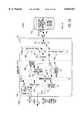
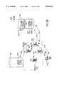
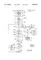
- FIGS. 1A-Cshow alternate embodiments of the current invention for client load rebalancing, distributed Input and Output (I/O), and resource load rebalancing. These embodiments allow more efficient robust communication between a plurality of clients and a plurality of resources via a plurality of nodes.
- Resourcescan include, but are not limited to, computers, memory devices, imaging devices, printers, and data sets.
- a data setcan include a database or a file system, for example.
- Nodescan include, but are not limited to, computers, gateways, bridges, and routers.
- Clientscan include, but are not limited to, computers, gateways, bridges, routers, phones, and remote access devices. Clients may be coupled to nodes directly over a network.
- Nodesmay be coupled to resources individually, or in combination, directly over a network.
- Client load rebalancingrefers to the ability of a client, enabled with processes in accordance with the current invention, to re-map a path through a plurality of nodes to a resource.
- the re-mappingmay take place in response to a redirection command emanating from an overloaded node, e.g. server.
- This capabilityallows the clients to optimize throughput between themselves and the resources accessed by the nodes.
- a networkwhich implements this embodiment of the invention, can dynamically rebalance itself to optimize throughput by migrating client I/O requests from over-utilized pathways to under-utilized pathways.
- a plurality of clientsinterface, via a plurality of nodes, with a resource.
- a memory resource 118, nodes, e.g. utilization servers 104A-106A, and clients, e.g., a normal client 100A, and an aware client 102Aare shown.
- Servers, nodes, and clustered file system nodes (CFNs) 104A-106Aare coinected to the storage resource through a private network 112.
- the private networkcan be implemented in any number of ways, provided that both server 104A and server 106A can access memory resource 118.
- the private networkcan include such interfaces as small computer system interface (SCSI), fibre channel, and could be realized, for example, with either circuit switch protocols, such as time division multiplexing (TDM), or packet switch protocols such as 802x.
- circuit switch protocolssuch as time division multiplexing (TDM)
- packet switch protocolssuch as 802x.
- Alternate implementations of private network 112, in accordance with the current invention,are set forth in each of the copending applications including International Application No. PCT/US97/12843 (Attorney Docket No. 16598.705), filed Aug. 1, 1997, entitled “Method and Apparatus for Allowing Distributed Control of Shared Resources" by inventors James J. Wolff and David Lathrop at pages 9-41 and FIGS. 1-5 which are incorporated herein by reference in their entirety as if fully set foith herein.
- the servers 104A-106Aarc both connected, via a network 108, to both the normal client 100A and the aware client 102A.
- the network 108may include any network type, including, but not limited to, a packet switch local area network (LAN) such as Ethernet, or a circuit switched wide area network, such as the public switch telephone network (PSFN).
- LANpacket switch local area network
- PSFNpublic switch telephone network
- normal client 100Ais shown accessing memory resource 118 via path 70 through overloaded server 104.
- aware client 102Ais shown accessing memory resource 118, via path 74, through overloaded server 104A
- process 102P1implemented on aware client 102A, detects the overload condition of server 104A, and accesses memory resource 118 via an alternate path 76 through server 106A.
- the load on server 104Ais reduced and the access by aware client 102A to memory resource 118 is enhanced.
- Normal client 100Acannot initiate the processes discussed above in connection with the aware client 102A and is unable to select an alternate path 72 to the underutilized server 106A.
- the detection of an overload condition on servers 104A-106Acan be made by processes 104PA and 106PA running on the servers.
- the overload conditioncan be detected by the client, on the basis of the round trip time for communications between aware client 102A and server 104.
- Re-mapping of an alternate pathcan be intelligently accomplished on the basis of an overall utilization and path table, or randomly, on the basis of client queries to alternate nodes in response to an overload condition.
- clientscommunicate across one network with nodes while the nodes communicate across another network with resources.
- the current inventioncan be applied with equal advantage on a single network on which clients, nodes, and resources coexist.
- a second resourcecould have a similar feature, e.g. a mirrored data set, and, in this instance, a determination to redirect would redirect to the second resource.
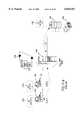
- FIG. 1Bshows an alternate embodiment of the current invention in which concurrent input/output through a plurality of nodes, e.g. servers, to resources, e.g. file systems 122 via memory resource 118, is provided.
- Concurrent access to a resourceallows a higher volume of I/O traffic to the resource, while maintaining file system integrity and security.
- concurrent access to a resourceis shown by splitting the traditional I/O request into an administrative portion and a data transfer portion.
- One nodehandles the administrative portion of all I/O to a given resource (volume/file system) through any of the plurality of nodes while all nodes, including the administrative node, may concurrently handle data transfers to and from the resource.
- FIG. 1Bincludes resources, e.g. file systems 122 located on memory resource 118, nodes, e.g. servers 104B-106B, and normal clients 100A.
- Memory resource 118includes a configuration database 120A-C and a plurality of resources (volumes/file systems), generally file systems 122.
- Servers 104B-106Binclude complementary processes 104PB-106PB for handling concurrent I/O requests from either of clients 100A for a file system resource on memory resource 118.
- the memory resource 118is connected, via private network 112, to both servers 104B-106B.
- Each of servers 104B-106Bcommunicate with normal clients 100A via network 108.
- one of the serversi.e. server 104B, is responsible for maintaining the integrity and security of the certain file systems 122 on memory resource 118, according to information stored in the configuration database 120A-C.
- a server that is responsible for a file systemis identified as the administrative server for that file system.
- Each file systemis assigned to be maintained by an administrative server.
- a server that is an administrative server with respect to one file systemcan be a data transfer server with respect to another file system.
- the administrative serverhandles the access, security, free space, and directories for the file system, e.g. the file system metadata in the form of the physical layout (on disk structure) of the file system.
- Both servers 104A-106Acan function as data transfer servers and handle the transmission or receipt of data to or from file systems 122 from either client.
- Processes 104PB and 106PBuse the configuration database 120A-C to determine, on the basis of entries in that database, which server is performing the administrative functions and which server is performing the data transfer functions for each resource.
- that serverlooks up the administrative server for that resource in the RAM resident dynamic version of the configuration database 120A-C and sends the I/O request to the administrative server.
- a response from that serverin the form of a block list of actual physical sectors on the memory resource 118, allows the data transfer server to handle the actual data transfer to/from the file system resource.
- the location of the data, at a physical level, being read from, or written to, the file systems 122is determined by the server running the administrative functions for that file system, e.g. processes 104PB on server 104B. Therefore, when normal client 100A makes an I/O request, via path 82, of server 106B for a file system 122 on memory resource 118, the following process in 106PB is engaged in by server 106B.
- Server 106Bpasses the I/O request, via path 84, directly to the administrative server 104B.
- the administrative serverdetermines if the request is from a client having access privileges to the specific file system 122. Processes 104PB then determine whether the request involves the allocation of additional free space and, if that is the case, allocates that free space.
- process 106PBdetermines the physical location on the memory resource 118 at which the specific file system resource request, including any allocated free space, resides.
- Processes 104PBthen pass, via path 84, a block list to the processes 106PB on server 106B.
- Subsequent I/O requests, e.g. reads and writes, to the specific blocks on the block listare handled by server 106B, via path 88, to volume/file system 122 on memory resource 118.
- client 100Amakes a request, via path 80, directly to the administrative server 104B for a file system 122, the I/O request is handled completely by processes 104PB. Since server 104B is both the administrative server and also has traditional I/O functional capability, the security and directory management function, as well as the data transfer function, is handled by the processes 104PB. I/O requests for the desired file system 122 are handled by server 104B via path 86.
- FIGS. 8, 10F-GSeveral embodiments of the current invention for distributing I/O functions to a resource, e.g. file systems 122, between a plurality of nodes, e.g. servers 104B-106B, are described in the following FIGS. 8, 10F-G, and in the accompanying text.
- a resourcee.g. file systems 122
- nodese.g. servers 104B-106B
- FIGS. 8, 10F-Ge.g. file systems 122
- the administrative processescan, when combined with the embodiment of the invention described in FIG. 1C, migrate from one server to another among the plurality of servers. This latter embodiment is useful when, for example, servers become disabled or off-line.
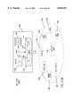
- FIG. 1Cshows another embodiment of the current invention in which resource rebalancing processes are set foith.
- Resource rebalancingincludes re-mapping of pathways between nodes, e.g. servers, and resources, e.g. volumes/file systems. Load rebalancing allows the network to reconfigure itself as components come on-line/off-line, as components fail, and as components fail back.
- Memory resource 118Aincludes configuration database 120A1-D1.
- the cluster configuration databaseincludes a clustered node database, a resource database, a directory/access table, and a database lock.
- Memory resource 118Aalso includes a plurality of file systems, generally 122A1-3, and associated directory and access tables. It will be apparent to those skilled in the art that each resource/volume/file system includes a directory and access table, which refers to the metadata associated with the resource, which, among other things, describes the physical layout of the resource.
- Memory resource 118Bincludes a plurality of file systems 122B1-3 and associated directory and access tables.
- Server 104Cincludes processes 104PC, while server 106C includes processes 106PC. In the example shown, server 106C has twice the processing capability of server 104C.
- Clients 100Aare connected via a network 108 to each of servers 104C-106C.
- Each of servers 104C-106Cis connected to both memory resources 118A-B, via private network 112.
- server 104Calone is operational.
- Processes 104PCcause server 104C to accept and process requests for any of file systems 122A1-3, and 122B13-3 on memory resources 118A-B.
- server 104Cis shown accessing file systems 122A2-3, via paths 90A, file system 122A1, via path 90B, and file systems 122B1-B3, via paths 90C.
- servers 106C and 104Care operational.
- server 106CWhen server 106C comes on-line, resident processes 106PC seize control of the configuration database 120A1-D1 by placing a lock in the lock portion 120-D1 of the database. While this lock is in place any other server attempting to rebalance the resources will see that rebalancing is taking place by another server when it fails to obtain the lock. Server 106C thus becomes the temporary master of the resource rebalancing process.
- the masteruses the configuration database records for all volumes and active nodes to rebalance the system. Rebalancing the system takes into account preferred resource-server affiliations, expected volume traffic, relative server processing capability, and group priority and domain matches, all of which are contained in configuration database 120A1-B1. Optimal re-mapping between the existing servers 104C-106C and the available memory resources 118A-B is accomplished by processes 106PC. These results are replicated to each server's copy of the dynamic RAM resident configuration database 120A2-B2. The results are published and received by processes 104PC, on server 104C, and the lock 120D1 is removed.
- server 106Ctakes on responsibility for handling, via path 92B, I/O requests for file systems 122B1-B3. Further administrative access to these file systems, via paths 90C, from server 104C ceases. An additional path 92A, between server 106C and file system 122A1, is initiated and the path 90B, between that same file system and server 104C, is terminated.
- server 106Chandles I/O requests for four out of the six file systems, namely 122A1, 122B1-B3, while server 104C handles only file systems 122A2-3.
- client load rebalancing and distributed I/Ocan be combined.
- Client load rebalancing and resource rebalancingcan be combined.
- Distributed I/O and resource rebalancingcan be combined.
- Client load rebalancing, distributed I/O, and resource rebalancingcan be combined.
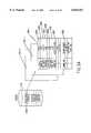
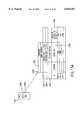
- FIG. 2Ashows the software modules present on server 104 for enabling client load balancing, distributed I/O, and resource rebalancing embodiments of the current invention.
- FIG. 2Ashows server 104 and memory resource 118.
- Server 104includes a logical I/O unit 130 and a physical I/O unit 132.
- the logical I/O unitincludes an internal I/O module 140, a resource publisher 146, a command receipt module 142, a shared data lock management module 144, a configuration database replicator module 148, a command processing module 154, a disk reader module 150, a shared data metadata management module 152, a server configuration driver 156, a resource management module 158, a logical name driver module 160, and a metadata supplier module 162.
- the physical I/O unit 132includes a scheduling module 164, an I/O store and forward module 166, a load balance driver 168, a screen driver 170, and a storage driver 172.
- the memory resource 118includes file systems 122 and configuration database 120.
- the command receipt module 142, the command processing module 154, and the resource publisher 146are all connected to the network 108 and private network 112 (see FIG. 1A-C.)
- the command processing unitis connected to the internal I/O module 140, the command receipt module 142, the shared data lock management module 144, the configuration database replicator module 148, the resource management module 158, the server configuration driver 156, the shared data metadata management module 152, the metadata supplier module 162, the disk reader module 150, and I/O store and forward 166.
- the resource management module 158is connected to the resource publisher 146 and to the logical name driver module 160.
- the metadata supplier module 162is connected to the shared data metadata management module 152.
- the scheduling module 164is connected to both the disk reader module 150 and to the shared data metadata management module 152.
- the I/O store and forward module 166is connected to a command processing module 154 and to the load balance driver 168, as well as the storage driver 172.
- the scheduling module 164is connected to the load balance driver 168.
- the screen driver 170is connected to a display (not shown).
- the storage driver 172is connected to memory resource 118.
- each of the modulesperforms in the manner specified in the following description.
- This moduleis the source where internally generated I/O (e.g. from an application on the node itself enters the processing system.
- the internal I/Ogenerates a command to command receipt module 142, and sends/receives I/O data through command processing module 154.
- This moduleis where file system I/O requests are received and queued up, either from internal I/O module 140, from the private network 112 (from a data transfer server), or from a normal or aware client on network 108.
- the I/Ois thus tagged with the source type for future decision making.
- This moduleis responsible for maintaining the network namespace describing the available resources on this node. It is the module that actually interacts with the network in order for normal and aware clients to figure out which resources are available on this node.
- the resource publisher 146interacts with the resource management module 158 and logical name driver module 160 to obtain the actual information that should be published in the network namespace.
- An example of informationwould be a list of file-shares (e.g. volumes) for which this node could accept I/O commands.
- This moduleis responsible for delivering resources for publishing in the namespace to the resource publisher 146.
- the resource managerinteracts with the logical name driver module 160 to obtain a translation of the proper resources and how they should appear in the network namespace, and provides a path for the logical name driver module 160 to communicate through command processing module 154, and server configuration driver 156, to build said namespace mapping information.
- This moduledetermines, in a consistent and logical manner, how the available resources should be presented in the network namespace.
- a logical namespacepresents a persistent view of the resources on the network, and a physical namespace presents the individual physical connection points used at any particular time to service the logical resources.
- This moduleis responsible for obtaining the next command for processing from the command receipt module 142, and dispatching it to various other modules for continued processing. This dispatching depends on the particular command, and also the source type that an I/O command was tagged with, in the command receipt module 142.
- This moduleis responsible for replicating the copy of required records of the configuration database 120 (see FIGS. 5A-D) stored in node memory to other nodes as a result of the server configuration driver 156 calling it. It is called when a node first appears on the network, during a fail-over, after a node failure, or when a node fails back. It guarantees that every online node has an identical copy of the server configuration database.
- These tablesreflect the current state of the servers/clustered file system nodes (CFNs) as a whole and specifically the individual state of each node for which the file system is the administrative server.
- This moduleis responsible for managing the server configuration database 120 (see FIGS. 5A-D), responding to requests from a node to get a copy of the current server configuration database (FIG. 10H process 1352), sending a command to set the configuration database (FIG. 10H process 1354), rebalancing the database in the case of a node coming up on the network, first time up or during fail-back and fail-over, and determining who the administrative server for a volume is, in response to an I/O by examining the server configuration database (see FIG. 10B).
- Command processing module 154calls server configuration driver 156 to determine whether this CFN is the administrative server for the I/O in question.
- This moduleis called by the command processing module 154 to determine if the I/O operation in question violates any locking semantics. Furthermore, this module is called to lock or unlock a range in a file (FIG. 10H process 1366, 1368). This module also cooperates in the caching and opportunistic locking mechanisms to efficiently cache administrative server block lists and break locks requiring cached file buffers to be committed (FIG 10H step 1364) to stable storage (see U.S. Pat. No. 5,628,005 for more information on opportunistic locking).
- This moduleis called by command processing module 154 and metadata supplier module 162 in order to translate a logical I/O operation into a physical I/O operation, resulting in a block list used to carry out the file I/O operation directly to the volume. If called from command processing /module 154, it then passes the physical I/Os onto scheduling module 164 for carrying out the I/O. If called from metadata supplier module 162. it simply returns the physical I/O translation back to metadata supplier module 162.
- This moduleis called by command processing module 154, in the case where an I/O operation is requested, in which the server configuration driver 156 has indicated that this node is not the administrative server for the file I/O operation in question.
- the disk reader module 150determines the administrative server for the I/O from the server configuration driver 156 and sends the I/O request onto the administrative server with a source type request message for translation into a physical I/O block list.
- the disk reader module 150instructs the server configuration database to be rebalanced by calling the server configuration driver 156.
- the physical I/O translation tableis returned from the administrative server's metadata supplier module 162, at which time the disk reader module 150 forwards the physical I/O onto scheduling module 164 for completion.
- This moduleis called by command processing module 154 as part of the process to service the receipt of an I/O request, tagged as Source Transaction Operation (STOP) type 1B I, during processing in command receipt module 142.
- This type of I/O operationis a request received by the administrative server's metadata supplier module 162 from a data transfer server's disk reader module 150.
- the metadata supplier module 162translates the logical I/O operation into a physical I/O block list and returns this table back to the disk reader module 150 that was the source of the I/O operation as a STOP-1B2 response message.
- the metadata supplier module 162obtains the logical to physical I/O translation by calling the shared-data metadata management module 152.
- This moduleis called to schedule physical I/O operations in an efficient manner. It can be called by the shared-data metadata management module 152, or disk reader module 150. In either case, it is given the information necessary to carry out the I/O directly to the memory resource(s) 118.
- This moduleis called upon during the carrying out of physical I/O operations to gather and periodically report load-balancing utilization statistics. It is responsible for maintaining counters and performing utilization calculations based on total I/O subsystem usage over time. Periodically, at a time determined by an update interval field in the cluster node database 120A (see FIG. 5A), it reports its usage to possibly several places, depending on the embodiment, including, but not limited to, a usage record in the cluster configuration database, a file server, or a load-balance monitor. Further, after each I/O operation, it determines if the current I/O utilization has exceeded the configured load-balance utilization threshold.
- This moduleis called upon to issue individual physical I/O operations and pass/store the related data into appropriate memory buffers.
- the I/O store and forward module 166simply gets/delivers the data from/to the memory buffers associated with the internal I/O.
- temporary memory resourcesare associated with the I/O, and data is gotten/delivered there.
- client generated I/Orequires the I/O store and forward module 166 to retrieve data from the client network, and send data to the client network, depending on whether the operation is write or read, respectively. After the client data is transferred, the temporary memory resources are freed to be used at another time.
- This moduleis called upon by the I/O store and forward module 166 to carry out the physical I/O to the physical storage bus.
- This drivertransmits/receives command and data to the storage resource to accomplish the I/O operation in question.
- This moduleis responsible for presenting a GUI of the OS and any application executing on the node that typically require human consumption of the visual information.
- FIG. 2Bshows software modules associated with an aware client 102A-B which interfaces with the network 108 (see FIG. 1A).
- the aware client software modulesmay reside on a server, which implements client processes, or a stand-alone unit as shown in FIG. 1A.
- the aware clientincludes a resource subscriber module 182, a redirector module 184, a resource management module 186, a fail-over module 188, a load-balancer module 190, a command processing module 192, a name driver module 194, and one or more application modules 196.
- the resource subscriber module 182 and the redirector module 184are both connected to the network 108 (see FIG. 1A).
- the redirector module 184 and the resource subscriber 182are both connected individually to the resource management module 186.
- the redirector moduleis also connected to the fail-over module 188 and to the application modules 196.
- the fail-over module 188is connected both to the name driver module 194 as well as to the command processing module 192.
- the load-balancer module 190is connected to the name driver module 194 and to the command processing module 192.
- the command processing module 192is connected to the resource management module 186, load-balancer module 190, and to the application modules 196.
- the name driver module 194is also connected to the resource management module 186.
- This moduleis responsible for retrieving from the network the namespace describing the resources available for use by the clients on the network. It interacts with resource management 186 to respond to a request for retrieval, and to redeliver the resource information.
- This moduleis responsible for managing the information about distinct resources available on the network and connection information associated with each. It calls the resource subscriber module 182 for gathering resource information from the network, and is called by redirector module 184 to determine resource to node path information. It calls name driver module 194 to gather multi-path information and conduct single system image (SSI) presentation and redirection. It is called by command processing module 192 to verify single system image resource to actual node translation information.
- SSIsingle system image
- This modulerefers to any application (process) running on the aware-client that generates I/O operations. It calls command processing module 192 to carry out the given I/O operation.
- This moduleis responsible for carrying out an I/O operation. It has to determine whether the requested I/O is destined for an internally controlled resource or externally controlled resource. If it is not a well-known, internally-controlled resource, it calls resource management module 186 which calls name driver module 194 to determine the appropriate (if any) resource to which this I/O is directed. It then passes the I/O for processing to fail-over module 188.
- This moduleis responsible for presenting the SSI to the system which is the enabling mechanism allowing transparent I/O recovery. It is called upon, in the case of load-balancing, to redirect future I/O for a resource to another node and, in the case of I/O recovery, to retry the I/O on another node. Both result in transparent I/O recovery and load-balancing.
- name driver module 194maintaining an abstraction mapping of the network namespace resources, and combining all available paths for each volume to each node as a single computing resource available for use by the rest of the system.
- Load-balancer module 190calls it to re-map future I/O while fail-over module 188 calls it to retry I/O on another path (see FIG. 6).
- Command processing module 192calls it to complete the I/O operation. Fail-over module 188 issues the I/O to redirector module 184. If the I/O fails, fail-over module 188 calls name driver module 194 to find an alternate path for the I/O operation, and reissues it. Upon success, data is returned to the I/O issuer (see FIG. 9B).
- This moduleis responsible for receiving a command to load-balance the aware-client from a node.
- aware-client load-balancingThere are several embodiments of aware-client load-balancing (FIGS. 7A-D).
- the receipt of a direct load-balance to a particular nodecauses load-balancer module 190 to call name driver module 194 to redirect future I/O (See FIGS. 7A-B).
- the receipt of a generic load balance requestcauses the load-balancer module 190 to perform one of the embodiments described in FIGS. 7C-D which again results in a call to the name driver module 194 to redirect future I/O to a particular CFN.
- This moduleis responsible for the communications between an aware-client and specific nodes to the physical client network. It receives I/O commands for execution from fail-over module 188 and gets/delivers data from the I/O directly from/to the memory buffers associated with the I/O (from the application modules 196). It also receives load-balancing commands from CFNs and passes them to the load-balancer module 190 for handling.
- the important aspect of this work groupis that the actual applications, and the clients that use them, exist on the computers that collectively make up the clustered file system. All I/O generated in this environment would automatically benefit from transparent I/O recovery and scaling, as the software that manages the clustered file system exists on each machine node in the workgroup and adds these capabilities.
- the clustered file systemis enclosed in that it uses a private network, based on Fibre Channel Standard (FCS), such as a FC-AL or switched fabric, for its node-to-node connections. This requires minimal security measures, because it is assumed any node connected in the private network can be trusted to directly access the storage subsystem in a proper, non-destructive, secure, law-abiding fashion.
- FCSFibre Channel Standard
- STOP-1Aspecifically refers to an I/O carried out by a CFN that is also the Metadata Server for the file system in question.
- STOP-1Bspecifically refers to an I/O carried out by a CFN that is not the Metadata Server for the file system.
- STOP-1B1is the communication from the CFN's Disk Reader to the Metadata Supplier of the CFN that is the Metadata Server.
- STOP-1B2is the communication from the CFN's Metadata Supplier that is the Metadata Server sending the block list to the Disk Reader on the CFN that originated the I/O.
- STOP-1B3is the I/O to the shared storage which is generated from the block list returned to the Disk Reader from the CFN that originated the I/O.
- the clustered file system I/O capabilities of a given clientcan take wo forms which we shall define as normal clients and enabled-clients.
- a normal clientis one, which has no special awareness of the clustered file system, and hence has absolutely no additional software installed in the computer. It sees the clustered file system as a normal network file system "file-share,” published in the namespace of the network, and thereby decides to attach to a single Clustered File System Node (CFN) as the server for access to that share.
- CFNClustered File System Node
- the clustered file systemis exposed to the public network as a series of symmetric file system server entry-points, each giving the client an identical view of the file system. All subsequent I/O from this client is carried out by the clustered file system through this single CFN.
- Availabilityis dealt with in the traditional way, by retrying the I/O until successful, or erroring out.
- An I/O failurecan occur, for instance, if the CFN to which the I/O was issued has crashed. If this occurs, it may become available at a later time, once restarted. In this respect, availability is the same as traditional client/server I/O.
- the client or applicationhas the option to manually attach to the clustered file system through another CFN in order to retry the operation. This recovery could be done automatically, but would have to be programmed into the issuing application.
- Scaling and load-balancingare accomplished through the symmetry provided by the clustered file system. This is done manually by distributing a group of normal clients among different attach points to the clustered file system, via the different CFNs that publish unique attach points in the namespace viewable by the normal clients. Distributed applications are supported in the traditional manner, save for much higher scaling limits, because the clustered file system supports a single view of the file system, no matter where it is viewed from, including the range-locking of files. Normal clients, attaching to the clustered file system through different CFN points, will see the exact same file system and hence the range-locks will be in effect regardless of which file was opened on which CFN.
- STOP-2A1is a normal client-generated I/O which occurs on the CFN that is the Metadata Server for the file system.
- STOP-2A2is a normal client-generated I/O which occurs on the CFN that is not the Metadata Server for the file system.
- An enabled-clientis one which has special clustered file system-aware software installed.
- the enabled-clienthas all the capabilities of a normal client, with some important additions.
- Clustered file system awarenessallows availability, scaling, symmetry, single system image, and load-balancing to transparently be extended to the public network.
- the enabled-clientnow views the exposed clustered file system as a single system image, not a group of symmetric nodes. This is an important abstraction that allows the virtualization of the clustered file system.
- the software on the enabled-clientpresents this single system image to the operating system and all client applications transact through this virtual interface.
- the softwaretranslates the I/O request to the virtual interface to an actual transaction to a particular CFN.
- Availabilityis automatic because I/O recovery is accomplished when the I/O to a failed CFN is redirected to another CFN for completion, after which, the original I/O is completed successfully back through the virtual interface.
- Scaling and load-balancingare accomplished automatically as the enabled-client is able to redirect I/O to another cluster node at the request of the clustered file system.
- Distributed applicationsfunction as well. All disk access is coordinated. Symmetry is achieved by allowing any file system I/O to function identically, regardless of which node initiated it.
- STOP-2B1is an enabled-client generated I/O which occurs on the CFN that is the Metadata Server for the file system.
- STOP-2B2is an enabled client generated I/O which occurs on the CFN that is not the Metadata Server for the file system.
- Availability businesscan continue when a server or component fails.
- STOP 1 availabilityis provided in terms of Metadata server fail-over and fail-back mechanisms, in order that the I/O can be recovered.
- STOP 2 availabilityis provided in terms of symmetry and virtualization through the single system image, allowing manual and transparent client I/O recovery.
- Coherencyis maintained partly by using a distributed lock manager. This allows an application to grow beyond the capacity of the largest available server. Multiple, high-speed paths to the data and range-locks, provided by the distributed lock manager, allow distributed applications to scale.
- STOP-1 and STOP-3scale directly with the clustered file system, while STOP-2 and STOP-4 scale as public network access to the clustered file system scales.
- Metadata Server and Hemingway Client cachecoordinates direct storage subsystem access.
- STOP-1 and STOP-3can execute applications on the same storage directly. If those are distributed applications, in the sense that they work together to manipulate a dataset, they will benefit from this symmetry.
- STOP-2 and STOP-4can utilize distributed applications that execute at the source, or services of such applications that execute on a server/cluster node in the same way. Everyone sees the same file system and can perform functionally identical I/O from anywhere.
- Virtualizationis particularly applicable to STOP 1 and STOP 2B (1,2), where a single system image of the file system is presented, allowing I/O recovery, application load balancing, and storage centric disaster tolerance. This is a key building block, allowing bigger than mainframe systems to be built incrementally.
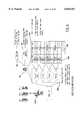
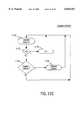
- FIGS. 3A-Cshow the functioning of the server node software modules, shown in FIG. 2A, for various implementations of distributed I/O handling shown in FIG. 1B.
- FIG. 3Ashows the software modules required for the administrative server 104B to handle both the administrative and data transfer functions associated with an I/O request (See FIG. 1B I/O request 80 and response 86). Processing begins by the receipt of an I/O request at command receipt module 142. The I/O request is tagged with the source identifier indicating the origin of the I/O request, e.g. client 100A (see FIG. 1B), and that request and tag are passed to the command processing module 154. The command processing module 154 determines that the I/O request should be passed to the server configuration driver 156.
- the server configuration driveruses information obtained from the configuration database 120A-C (see FIGS. 1B, 5B) to determine which, among the plurality of servers 104B-106B (see FIG.
- Controlpasses from the server configuration driver to the shared data lock management module 144.
- This moduleis called by the command processing module to determine if the I/O operation in question violates any locking semantics. Assuming there are no access violations, control is then passed by the command processing module to the shared data metadata-management module 152.
- This moduleis called by the command processing unit in order to translate a logical I/O operation into a physical I/O operation, resulting in a block list used to carry out file I/O operations directly to the file system.
- This modulepasses physical I/O operations on to scheduling module 164.
- Scheduling module 164schedules the physical I/O operations in an efficient manner. Control is then passed to load balanced driver 168. This module gathers and periodically reports load balancing utilization statistics, which statistics can be utilized for client load balancing (see FIG. 1A). Control is then passed to the I/O store and forward module 166.
- the I/O store and forward moduleis responsible for handling the individual physical I/O operations where data is passed between the network and the storage module through the command processing module 154, the I/O store and forward module 166, and the storage driver 172.
- the storage driver 172carries out the actual physical I/O interface with the memory resource 118.
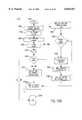
- FIGS. 3B-Cshow the complementary relationships associated with distributed I/O between an administrative server and a data transfer server, in accordance with the embodiments shown in FIG. 1B.
- FIG. 3Bshows the software modules associated with the handling of an I/O request by the data transfer server 106B
- FIG. 3Cshows the software modules associated with handling the administrative portions of the I/O request, initially received by data transfer server 106B, and handled administratively by administrative server 104B.
- Processing in FIG. 3Bbegins with the receipt of an I/O request by the command receipt module 142.
- a requestis tagged by source and passed to the command processing module 154.
- the command processing modulepasses the request to the server config driver which determines it is not the administrative server for the resource I/O request.
- Command processing module 154then calls disk reader module 150.
- the disk reader module 150determines the administrative server for the volume on which the requested file system resides. Control is then passed to the command receipt module 142 which sends to the administrative server the I/O request. If the I/O is read or write, then the logical I/O is passed to the administrative server for translation to physical sectors on the resource to which the read or write I/O request should be directed.
- the command processing module 154receives the response to that request, in the form of a block list, and receives the response to that request, in the form of a block list.
- the command processing modulepasses the block list to the disk reader module 150.
- the disk reader moduleforwards the physical I/O locations from the block list to the scheduling module 164.
- the scheduling module 164schedules I/O operations in an efficient manner.
- Controlis then passed to the load balance driver 168, which accumulates utilization statistics based on I/O requests, and which periodically reports these. These statistics are useful when implementing the client load balancing embodiments and resource rebalancing embodiments of the invention, described and discussed above in connection with FIGS. 1A-C.
- Controlis then passed to the I/O store and forward module 166.
- the I/O store and forward modulepasses data between the network and the memory resource 118 via the command processing module 154, the I/O store and forward module 166, and the storage driver 172.
- the storage modulecarries out the physical I/O
- FIG. 3Cshows the software modules associated with the handling by an administrative server 104B of a distributed I/O request passed from a data transfer server 106B (see FIGS. 1B, 3B). Processing begins with the receipt of an I/O request. If it is a read or write I/O request, then the logical I/O needs to be translated into storage device ID(s) and physical sector list for the distributed I/O request which is received from the data transfer server by command receipt module 142. The request is tagged with source information by the command receipt module and passed to the command processing module 154. The command processing module determines, on the basis of I/O type and source, that the request is passed to the server configuration driver 156. The server configuration driver 156 obtains a copy of the current configuration database 120 (see FIG.
- Controlis then passed to the shared data lock management module 144 to determine whether any locking semantics are violated. If that determination is in the negative, the I/O request to the file in the file system does not violate any locks of another process, then control is passed to the metadata supplier module 162.
- the metadata supplier module 162calls shared data metadata management module 152 to translate the logical I/O operation into a physical I/O block list. The request, in the form of a block list, is then passed by the command processing module 154 over the network to the data transfer server 106B.
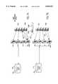
- FIGS. 4A-Dshow the software modules associated with the handling of I/O by an aware client, the handling of a fail-over and fail-back by an aware client, and the passive and active management of load rebalancing by a client.
- FIG. 4Ashows which of the software modules, described and discussed above in FIG. 2B, are involved in the processing by an aware client of an I/O request.
- Processingbegins with an I/O request generated by application modules 196. That request is passed to the command processing module 192.
- the command processing moduledetermines whether the requested I/O is destined for a client controlled resource or an externally controlled resource.
- the command processing module 192calls the resource management module 186. This module is responsible for managing the information about distinct resources available on the network and the connection information associated with each.
- This modulecalls the name driver module 194 which presents a single system image to the system. The single system image allows for multiple paths to any specific resource and enables transparent I/O recovery.
- the named drivermaintains an abstract mapping of network namespace resources and combines all available paths for each volume through the plurality of nodes, e.g. servers (see FIG. 6).
- the current path for the resourceis returned to resource management 186.
- the I/Ois sent to the appropriate destination by the redirector module 184. This module handles communications between the aware client and the network. Data passing to or from the client, in response the I/O request, is passed between the network and the application modules 196 via the redirector module 184.
- FIG. 4Bshows which of the software modules, described and discussed above in connection with FIG. 2B, is associated with the processing by an aware client of a fail-over or fail-back on the network.
- Fail-overrefers to the response, by aware clients seeking access to a resource, to the failure of a node, e.g. server, designated in the name driver module 194 for accessing that resource.
- Fail-backdeals with the behavior of an aware client in response to a recovery of a node, e.g. server, on the network from a failed condition.
- the operationbegins, in a manner similar to that described and discussed above in connection with FIG. 4A, with the issuance of an I/O request by the application module 196. That request is passed to the command processing module 192.
- the path to the resourceneeds to be determined.
- the requestis therefore passed to the resource management module 186 and to the name driver module 194 to obtain the path.
- Ilhe command processing module 192passes the request with path information to fail-over module 188 for further processing.
- Fail-over module 188then calls the redirector module 184 to send the I/O request via the path obtained from the name driver. If fail-over module 188 determines that there is a failure, it calls the name driver module to provide an alternate path for the I/O operation, and the fail-over module 188 reissues the I/O command with the alternate path to the redirector module 184.
- Data passing between the resource and the application module 196is passed via the redirector module 184.
- name driver module 194Upon failure detection and redirecting by fail-over module 188, name driver module 194 marks the path as failed. Periodically, name driver module 194 checks the network for the valid presence of the failed paths and, if good, once again marks them failed-back or valid so that they may once again be used in the future, if necessary.
- FIGS. 4C-Dshow the software modules on the aware client associated with what are defined as passive and active embodiments of client load rebalancing, introduced above in FIG. 1A.
- FIG. 4Cdiscloses a software module associated with passive client load balancing
- FIG. 4Dshows the software modules associated with active client load balancing.
- Passive load balancingrefers to the activities on a client subsequent to the receipt from a utilization server (see FIG. 1A) of a redirect command and, potentially, an alternate path or paths for the I/O request to a file system.
- Active client load balancingrefers to the activities of an aware client, subsequent to the receipt from a utilization server of a redirect command, without any accompanying information as to which path(s) through which to direct subsequent I/O requests for a particular file system.
- Passive client load balancingcommences in FIG. 4C with the receipt, by redirector module 184, of a redirect command from a utilization server (see FIG. 1A).
- the commandis passed to the load balancer module 190 via the command processing module 192.
- the receipt of a redirect commandcauses load balancer module 190 to call name driver module 194 and to redirect all future I/O to the requested file system through an alternate server path.
- the name drivermaintains an abstract mapping of network namespace resources which combine all available paths of each file system to each server.
- the name driverupdates its abstract mapping of network namespace, nodes, and resources to reflect the new path (see FIG.
- an embodiment of the inventionUpon receipt of a redirect command without path information, an embodiment of the invention has the aware client in passive load balancing choosing any other valid path for redirection. This is usually done by choosing that path which was least recently redirected, e.g. the oldest redirected path (see FIG. 6).
- FIG. 4Dshows the software modules in the aware client (see FIG. 1A) associated with active load balancing. Processing is initially similar to that described and discussed above in FIG. 4C, with the following exception.
- the incoming redirect command from the utilization serverindicates only that redirection is required but not what path should be followed for the redirection. That decision is left to the aware client to actively make, based on utilization information, not just based on valid path.
- the load balancer module 190engages in the following activity.
- the load balancer module 190accesses the name driver module 194 to determine suitable alternate paths and, additionally, accesses the cluster configuration database in the memory resource 118 (see FIG. 1A) to determine which, among the servers on the alternate paths, is the least utilized, and to choose that as the alternate path.
- the load balancer module 190accesses the name driver module 194 in response to the redirect command to determine valid alternate paths.
- the clientqueries each of the individual servers on the path to determine their utilization and selects that server which is the least utilized.
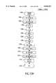
- FIGS. 5A-Dshow the data structures which comprise the configuration database 120 (see FIGS. 1A-C).
- the configuration databaseis an optional feature, the only portion of which may be utilized being the node, e.g. server, cluster database shown in FIG. 5A.
- FIG. 5Ashows a record for node 1, node 2, and node N which represents the plurality of records contained in the clustered node database.
- Fields 420A-I within the node 1 recordare shown.
- Name field 420Acontains the node name, i.e. "CFN 8."
- a node in the examples shown in FIGS. 1A-Ccomprises a server.
- a nodecan include any network attached processor embodied in servers, workstations, computers, routers, gateways, bridges, storage devices, printers, cameras, etc.
- Field 420Bis the node weight field which, in the example shown, is assigned a weight of "2.00.” Node weight may correlate with the relative processing capability of the node.
- Field 420Cis the utilization update interval which, in the example shown, is listed as one minute. This interval indicates how often the node will update the current utilization field 420E.
- Field 420Dis an optional utilization threshold field which, in the example shown, is set at "80%.” The following field, 420E, is the current utilization which, in the example shown, is "21%.” Utilization may refer to I/O utilization, processor utilization, or any combination thereof. Utilization threshold refers to that level of I/O or processor activity which corresponds to 80% of the hardware capability on the particular node. When that level is reached, client load rebalancing may be triggered in a manner which will be described and discussed in the following FIGS. 7A-D.
- Fields 420H-Icontain variables which indicate the ideal node capacity and remaining node capacity.
- ideal capacityis an indicia of the portion of the clustered resources with which each specific node should be associated. In the example shown in FIG. 5B, this correlates with weights (field 440H) which are assigned to resources.
- Field 420Fcontains, for each specific node, the preferred groups in order of precedence with which each specific node should preferentially be associated.
- a groupe.g. sales, accounting, engineering, etc., may be defined as a combination of file systems. In other embodiments of the invention, a group comprises more broadly defined resources, e.g. printers, storage devices, cameras, computers, work stations, etc.
- Field 420Gcontains the domains with which the specific node can be associated, e.g. LA sales, California Engineering, Texas G&A. Some other examples of domains may be locations, such as CA, MI, NY, TX, to indicate states, or logical associations such as Accounting, Sales, and Engineering. Whereas a group defines categorizations of resources, a domain defines a physical relationship between a node and a resource. For example, if no physical link exists directly between a node and a resource, then the domains listed in 420G in the node, e.g. server or record, will not correlate with the domain associated with the resource (see FIG. SB). Domains may also be used to provide logical separations. For example.
- FIG. 5Bshows the resource database 120B, and the plurality of records for volume 1, volume 2, and volume N are shown.
- resourcesmay, in alternate embodiments of the invention, include volumes, printers, cameras, or computers, or combinations thereof.
- the record of volume 1is shown in detail. That record includes fields 440A-L.
- Field 440Ais the volume name field which, in the example shown, is "PO DB storage.”
- Fields 440B-Ccontain the volume group number and name which, in the example shown, are "3" and "sales,” respectively.
- Fields 440D-Econtain the parent administrative node and administrative node number which, in the examples shown, are "CFN8" and "1," respectively.
- Fields 440F-Gcontain the current administrative node and the current administrative node number which, in the example shown, are "CFN8" and "1," respectively.
- the current and parent administrative node fieldsare best understood in the context of the invention shown in FIG. 1B.
- the parent administrative nodemay correspond to the particular node which a network administrator has preferentially associated with a specific resource.
- the administrative node of a volumeis the server which handles at least the administrative portion of I/O requests for file system resources.
- the current administrative nodeis the node with which the resource is currently affiliated.
- a clustered systemthere are a plurality of nodes which are eligible for performing the administrative server functions for a specific volume.
- the determination of which server can perform administrative server functions for a volumeis based on a comparison of fields 440J-K of the volume record with fields 420G of the server record. These fields list the domain and domain members for a volume resource record and a server resource record.
- a resource/volume and a node/servermust have one domain in common, i.e. overlapping, in order for the node/server to be a candidate for performing the administrative server functions. Further, it must either have a group overlap between 440B-C and 420F, or the field "can group migrate" 440I must be set to Boolean True.
- volume 1has a domain "LA-sales,” shown in fields 440J-K.
- An eligible node for that volumeis a node which, in the clustered node records (see FIG. 5A), contains in its domain fields 420G--a domain corresponding to the domain in the volume record.
- volume 1may be affiliated with node 1 because node 1 has, among its plurality of domain members in fields 420G, the domain "LA-sales.”
- Field 440Iin each volume record in the resource database, indicates if the group with which the volume is associated can migrate, i.e. be administratively handled by another node in which 420F does not overlap 440B-C.
- Field 440His the volume weight field.
- volume 1is assigned a weight of "3.0.”
- the volume weightis a measure of the importance of a specific volume and may additionally correspond to the expected demand for a volume. For example, a back-up volume may have a lower weight than a primary volume, as the backup is seldom accessed.
- the remaining field 440Lcontains Boolean True or False, and indicates whether a volume record needs to be replicated to the memory of other nodes. In the example shown, field 440L contains the Boolean False, indicating that no replication is required.
- fields 440F-Gare dynamic, and if field440L is set to Boolean True, only the portion of the record comprising fields 440F-G needs to be replicated, e.g. to be transmitted to other nodes (see FIGS. 9A-E, 10B-C).
- FIG. 5Cis a detailed data structure diagram for a uniform file directory format which can be implemented in the directory/access database 120C of the cluster configuration database.
- each resource/volume/file systeme.g. self-contained file system, contain a directory/access portion to maintain the physical layout of the file system.
- Alternate implementations of private network 112, in accordance with the current inventionare set forth in the copending applications including International Application No. PCT/US97/12843 (Attorney Docket No. 16598.705). filed Aug. 1, 1997, entitled “Method and Apparatus for Allowing Distributed Control of Shared Resources" by inventors James J. Wolff and David Lathrop at pages 14-19 and FIGS.
- volume record 454Shown in FIG. 5C for the directory/access database are a volume record 454, a directory record 456, a file record 458, and a file location record (Extent) also known as a block list 460.
- This directory structureis generally associated with the HFS file directory format associated with the System 8 operating system provided with the Macintosh® computers.
- the volume record 454contains the name of the volume, its creation date, its update date, a software lock, a listing of attributes and privileges, a volume availability bit map, and a number of other parameters broadly defining the physical volume.
- Associated with the volume record 454is a plurality of directory records of which record 456 is referenced.
- Each directory recordincludes a pointer to a parent directory, a name, a creation time, and a modification time.
- file record 458is referenced.
- Each file recordcontains a name, a type, a lock indicator, a creation and modification time, and other file level information.
- block list 460is referenced.
- Each file location recordincludes a pointer to the physical address at which the file starts and an indication as to the length of the file. If a file is stored in noncontiguous segments, then there will be an overflow indicator indicating the physical address of the next portion of the file and the length of that portion.
- the file location record addresses and address lengthscorrespond to the actual physical address locations of the file contents.
- Each operating systemhas its own file directory structure, differing in numerous aspects from the one disclosed in FIG. 5C.
- FIG. 2Cprotocol conversion modules 268 associated with each of client processes 214-216
- there is enforcement of a uniform file directory formatnotwithstanding the operating system on each client.
- This processassures that there is cross-platform compatibility (operability in a heterogeneous computing environment) between any application on either of the clients, notwithstanding the OS that may be present on the client.
- a client running a Macintosh System 8® operating systemcan read or write a file created by another client operating with a Microsoft® Windows NTO, SGI® IRIXO, or SUN® SolarisO operating system.
- the use of the clustered node database in an embodiment of client load balancing shown in FIG. 1Aallows alternate paths between clients and resources to be determined in an intelligent manner based on the overall system architecture mapping contained in the clustered node database 120A.
- distributed I/O shown in FIG. 1Ball portions of the clustered configuration database, with the exception of the lock 120D, may be utilized.
- the lockis not required since distributed I/O does not require an alteration to the information stored in either the clustered node database 120A, the resource database 120B, or their directory/access database 120C. What distributed I/O does require is a known repository for maintaining information as to the designated administrative server/node for each volume/resource.
- all portions of the configuration database 120A-Dmay be utilized.
- the lock 120Dis required because load balancing involves changing information contained in the clustered configuration database, and the lock insures that only one node can do this at a time.
- FIG. 5Dshows the functional relationship of the databases, illustrated in FIGS. 5A-C, and the resources and nodes.
- Nodes CFN 1-10, memory resources 500A-D, configuration databases 120A-D, and file systemsare shown.
- Servers CFN 1-7are associated with the group Engineering.
- Servers CFN 5-8are associated with the group Sales.
- Servers CFN 8-10are associated with the group Accounting.
- CFN 8therefore, is associated with both the Sales and Accounting groups.
- CFNs 5-7are associated with both the Sales and Engineering group.
- Engineeringwould appear as the first of the group priorities in field 420F of the node record for servers CFN1-4.
- the configuration database 120A-Dresides in one location which, in the example shown, is memory resource 500D in a domain ALL, indicating all nodes have access to it, and includes the clustered node database 120A, the resource database 120B, the directory/access database 120C, and a lock 120D.
- the lockis utilized by whichever node is taking on the master role shown in FIG. 1C and replicating RAM copies/rewriting the configuration database.
- FIG. 6shows an update table 600 maintained on an aware client 102A, in accordance with an embodiment of client load balancing first introduced generally in FIG. 1A.
- the table shown in FIG. 6may be generated by an aware client implementing an embodiment of client load balancing.
- An embodiment of client load balancinginvolves client decision making as to an alternate path to a resource, subsequent to the receipt of a redirect command from a utilization server.
- a clientas discussed above in connection with FIGS. 4C-D can passively redirect as told, passively pick any valid path, actively query other utilization servers, or actively obtain a copy of the clustered node database 120A of the configuration database 120 (see FIG. 1A).
- the update table 600is generated by the combined action of the fail-over module 188, the name driver module 194, and the load balancer module 190 first set forth and described in FIG. 2B.
- the name driver module 194may maintain a list similar to update table 600, which records for each file system resource 606 the nodes 604 through which the file system can be accessed, and for each of those nodes the time 602 at which the node was most recently used as an access point to the specific file system. On the basis of this list, a new path would be chosen subsequent to the receipt of a redirect command in the following manner.
- the load balancer module 190would look at the update table 600 in the name driver and would choose that node having access to the specific file system for which it has been instructed.
- the choice based on the node least recently used as an access point for that file systemis the node to which to redirect the I/O request.
- fail-over module 188retires the I/O on another path based on the oldest time stamped path (least recently redirected).
- module 188the node to which a failure was detected, is marked as failed.
- name driver module 194sees if failed nodes have failed-back, and, if so, marks them as such so they may be considered for future I/O paths again.
- FIGS. 7A-Dshow details of alternate embodiments of client load balancing introduced above in connection with FIG. 1A.
- FIGS. 7A-Bshow, generally, the context in which passive client load rebalancing embodiments are implemented.
- FIG. 7Ashows the condition before a rebalance.
- FIG. 7Bshows the condition after a rebalance.
- FIGS. 7A-Bboth show a plurality of aware clients 102A and normal clients 100A interfacing with a plurality of nodes, e.g. servers, one of which is referenced as server 104A.
- Each of the serversinterfaces with a clustered node database 120A which is shown on memory resource 118.
- Memory resource 118may be a network attached peripherally or may itself be handled independently by a file server or load-balance monitor server or process.
- the cluster node database 120Amay, alternatively, be resident in the memory in each of the nodes.
- the cluster node database 120Ais maintained by periodic updates from each of the nodes as to their current utilization. Utilization can, for example, correlate with processor activity as a percentage of total processor capability, and/or I/O activity as a percentage of total I/O capacity.
- node 4i.e. server 104A
- server 104Ahas detected a utilization condition in excess of an overload threshold. Responsive to that determination, server 104A reads the clustered node database 120A in whatever location it may reside, e.g. volatile or non-volatile memory, on a storage volume resource, or in node memory.
- the server 104Adetermines which, among those clients that account for its current I/O activity, is an aware client.
- An aware clientconnects with a utilization server with a message indicating to the utilization server that the client is capable of running aware processes 102P1 (see FIG. 1A). In the example shown in FIG. 7, aware client 3 is sending I/O request 702 to server 104A.
- Server 104Aadditionally determines, on the basis of the clustered node database 120A, which among the remaining nodes 1-3 has access to the file system and aware client, and which among the remaining nodes 1-3 is the subject of the I/O request 702 from aware client 3.
- the utilization server 104Athen sends a redirect packet 700, including a command portion 700A and an optional path portion 700B.
- the command portion 700Acontains a generic command and the optional path portion 700B contains the alternate path, e.g. alternate node, through which the aware client may request the file system in the future.
- aware client 3responsive to the receipt of the command packet, redirects I/O for the subject file system along path 704 through node 3.
- the utilization level at node 4is decreased.
- the clientsimply redirects future I/O to the least recently redirected, e.g. oldest, valid path.
- FIGS. 7C-Dshow alternate embodiments of client node rebalancing, known as active load rebalancing, in which the aware client, having received a redirect command, performs the intelligent utilization decision making associated with choosing the actual redirect path.
- FIGS. 7C-Dshow the plurality of aware clients 102A and normal clients 100A communicating via nodes 1-4 with file system resources on a memory resource 118.
- the memory resource 118can be either a network-attached peripheral, accessible through a plurality of nodes, or can be accessed through a fileserver.
- aware client 3 and normal clients 1-2are sending I/O requests 712 for a file system through node 4, e.g. server 104A.
- Server 104Adetermines ,on the basis, for example, of a stored threshold value, that it is experiencing an overload condition.
- Server 4then sends a redirect packet 710 to the aware client 3.
- the redirect packet 710contains a command portion 710A but does not contain a redirect path, as did the redirect packet in FIG. 7A. Thus, it is up to aware client 3 to determine an intelligent, acceptable redirect path.
- the redirect pathcan be determined by aware client 3 on the basis of the clustered node database 120A.
- the clientcan poll each of the nodes to determine their current utilization and put together a table similar to the tables shown in the following tables CLB-1 and CLB-2. Based on these tables, an intelligent decision as to an alternate path can be made based on the percentage utilization of alternate nodes.
- a redirect path 714has been established between aware 3 and Node 3.
- Tables 1-2show a composite view of a load balance table obtained by a node/server from the configuration database 120, in accordance with the passive embodiment of the client load balancing invention disclosed in FIG. 7A-B.
- the tableis a composite view that may be obtained by a node/server from the node and resource databases 120A-B of the configuration database 120.
- CLB1 and CLB2show the condition of the associated records in the configuration database before and after a load rebalance.
- CFN4Before load rebalance, CFN4 is at 95% utilization, while CFN 3 has 0% utilization. CFN 4 is in an overload condition in that its current utilization level exceeds its load balance threshold (LBTH) of 80%. If there is domain overlap for the volume record associated with the requested file system and the server record for CFN 3, i.e. in fields 440J-K and 420G, and aware 3 is in the same domain, then the I/O requests 702 can be redirected from CFN 4 to CFN 3.
- LBTHload balance threshold
- aware 3After load balancing, as shown in Table 2, aware 3 sends I/O requests along path 704 for the file system via CFN 3. As a result, utilization on CFN 4 has dropped to 70% and is below the load balance threshold. Thus, the clustered system of nodes, resources, and clients has balanced the load on nodes/servers by redirecting client I/O requests.
- load balancingmay be initiated, not by the nodes sending a redirect command, but rather by the clients' detection of delays in the processor utilization of the nodes and/or the I/O utilization of the nodes.
- Each clientwould maintain a table, listing this utilization, and make decisions similar to those discussed above in connection with FIGS. 7A-D to balance out the load.
- the issuance of a redirect commandwould be based not on utilization above a threshold, but rather on averaging the utilization levels of all active nodes and redirecting I/O requests to those nodes with utilization levels below the average utilization level.
- FIG. 8shows the communication between a data transfer server and administrative server and the connection with distributed I/O processing, shown and discussed above in connection with FIG. 1B.
- the data transfer server 106B, the administrative server 104B, and the memory resource 118Aare shown interfacing over a private network 112.
- server 106Btransfers that request 84A in the foim of a file I/O, offset, and amount to the node listed in the RAM resident version of resource database 120B as the administrative server for that file system resource, e.g. server 104B.
- the server 104Bexecutes a process, first introduced above in connection with FIG. 1B, determines any security or access issues, and then determines, if there are no such issues, the physical location of the file sectors on memory resource 118 to which the I/O requests for file systems 122 should be directed.
- the administrative serverreturns this information 84B in the form of a block list 460 and device ID 462, such as that shown in FIG. C.
- the data transfer server 106Bhandles all the subsequent processing connected with the reading or writing of data to or from the memory resource 118 on which the requested file system 122 resides along path 88.
- a servercan be concurrently performing processes initiated by I/O requests to different file systems, for some of which it performs as a data transfer server, for others as an administrative server, and for still others as both.
- FIGS. 9A-Eshow various details related to resource load rebalancing, introduced above in connection with FIG. 1C.
- Resource load rebalancingcan occur on demand, in response to a new node coming on line, in the event of system fail over and in the event of a fail-back.
- FIG. 9Ashows four nodes, 1-4, one node of which is a server, referenced as server 104C, which has just come on line, and therefore needs to enter the configuration database. This is accomplished by server 104C obtaining temporary master status with respect to the rebalancing of the configuration database. Master status is initiated by server 104C placing 900 a semaphore/tag/lock 120D1 on the configuration database thereby preventing, temporarily, any other node from seizing control of the configuration database. Server 104C obtains a copy of the configuration database 120 either from memory resource 118, if it is the first node up, or from another node that is already up, and begins the processes which will be described and discussed in greater detail in connection with FIGS.
- server 104Cobtain temporary master status with respect to the rebalancing of the configuration database. Master status is initiated by server 104C placing 900 a semaphore/tag/lock 120D1 on the configuration database thereby preventing, temporarily, any other node from seizing control of the configuration database
- FIG. 9Bshows an overall environment in which a failure of one or more nodes prompts resource load rebalancing.
- An aware client 102A, clustered nodes 1-4, and memory resources 118A-Bare shown.
- Memory resource 118Acontains a configuration database 120A1-D1, a plurality of file systems 122A1-A3, and a directory and access table for each file system.
- Memory resource 118Bcontains a plurality of file systems, of which file system 122B1 is referenced. Additionally, memory resource 118B contains, for each file system, a directory and access table.
- aware client 102Asends an I/O request 920 via node 3 for a file system 122B1 on memory resource 118B.
- the absence of a response to that request, resulting from the failure of node 3,causes the aware client to obtain from its namespace an alternate node through which the file system may be accessed.
- Node 4appears in the configuration database as having a domain that overlaps with the domain of the file system.
- a server and a resourceare said to be in the same domain space if the domain fields 440J-K (see FIG. 5B) for the resource record overlap with one of the domain members in fields 420G (see FIG. 5A) of the node/server record in the configuration database.
- aware client 102Asends an I/O request 922 to node 4.
- Node 4looks at a copy of the configuration database in its memory and determines that there is an administrative server for file system 122B1, and that the current administrative node fields 440F-G (see FIG. 5B) indicate node 2.
- node 4initiates an I/O request 924 to node 2, the designated administrative server for file system 122B1.
- no response to that I/O requestis received, and node 4 concludes that the administrative server for the volume has failed.
- node 4seizes the lock 120D1 for the configuration database and thereby obtains master status with respect to the onset of resource rebalancing which it has initiated.
- Node 4accomplishes rebalancing which will be discussed in greater detail in FIG. 10B-D.
- a new administrative server for each file systemmay be chosen. Different file systems may have different administrative servers.
- node 1is designated as administrative server for file system 122B1.
- Node 4during the interval over which it has master status, appoints additional administrative servers for each resource as necessary to rebalance the resources according to the configuration policy dictated by the clustered configuration database.
- node 4may send an updated copy 926 of the configuration database to memory resource 118B.
- Node 4replicates the configuration database by sending a replicated copy 928 of changes to clustered nodes, including node 1, and may update 934, the configuration database 120A1-C1, and remove the lock 120D1.
- the I/O request 930is passed from node 4 to node 1.
- the transfer of data 932A-B, between aware client 102A and file system 122B1is accomplished.
- load rebalancingmay be implemented without distributed I/O by defining a single server as an access point for each file system at any point in time.
- FIGS. 9C-Eshow redistribution of I/O requests between file system resources and node resources as more node resources become available.
- FIG. 9Cshows four file systems, 950-956, labeled as source code, finance, contacts, and backup, respectively. These file systems may reside on one or more nodes/storage devices.
- CFN 1is shown handling the I/O requests for file systems 950 and 956.
- CFN 2is shown handling the I/O request for file systems 952-54.
- CFN 1is shown handling I/O requests to file system 950.
- CFN 2is shown handling I/O requests to file system 954.
- CFN 3is shown handling I/O requests to file systems 952 and 956.
- the following tablesshow the alterations to the volume database records in the configuration database that occur as each new node that comes on-line takes on master status and rebalances the configuration database. Rebalancing will be described in detail in FIG. 10B-D.
- node 1i.e. CFN 1
- CFNthe current administrative node for each of file systems 950-56.
- all file systems 950-56have a specific name, group affiliation, and administrative node/server preference. Additionally, all file systems 950-56 can migrate and can be accessed by any server/node, no matter what the domain affiliation of the node is.
- Node weightmay be an indication of server processing capability or I/O capabitity.
- the resource rebalancing processis described in detail in the description of FIGS. 10B-D, however briefly, and an example of what occurs in this process is descibed next.
- the server that has master statusadds up the volume weights of all existing volumes which, in the current case, total 7.
- the masterthen adds up the total node weight of all available nodes, e.g. servers.
- a balanced volume weightis established for each of the available servers.
- the volume limit for each serveris based on the simple calculation which establishes the server's node weight as a percentage of the total of all available servers' node weights and multiplies that by the sum of all volume weights.
- a resultant number greater than 1is the volume limit for that server.
- volume weightis added to the total weight of all volumes assigned to this server and compared to the limit. When the limit is reached, generally no further volumes will be assigned to that server. In choosing which is to assign to which server, several factors are considered. First, a server will be perentially assigned to a volume which lists the server as a preferred administrative server. Second, where a match between a volume and a server, listed as the volume's preferred administrative server, is not possible, an attempt will be made to match a volume with a server on the basis of the volume's group affiliation and the server's group priorities.
- node 2e.g. CFN 2 is on-line, as indicated in FIG. 9D. That server has an identical node weight of 1 to that of CFN 1. Therefore, each of those servers should be the administrative server for volumes whose total volume weight is 3.5, or half of the weight of all volumes/file systems 950-56.
- CFN 1is affiliated with file system 950, for which it is listed as the administratively preferred server, and with file system 956, for which it is not listed as the administratively preferred server.
- the total weight of the volumes to which CFN 1 is assignedis 3, or 42% of the total volume weight.
- CFN 2is assigned to file system 952 and to file system 954, for which it is listed as the administrative server.
- the total weight of the volumes to which it is assignedis 4, or 57% of the total volume weight.
- CFN 3has come on-line and it has a node weight of 4, reflecting significantly greater I/O and/or processing bandwidth than that of either CFN 1 or 2.
- CFN 3should therefore be administratively affiliated with a high percentage of the total volume weights.
- CFN 1is the current administrative server for file system 950 for which it is designated as the preferred administrative server.
- the total volume weight assigned to CFN 1is 2, or 28% of the total.
- CFN 2is assigned to file system 954 for which it is the preferred administrative server.
- the total volume weight assigned to CFN 2is 2, or 28% of the total.
- CFN 3is assigned to both file systems 952 and 956, for each of which it is also listed as the administrative preferred server.
- CFN 3is assigned volumes whose total weight is 3, or 42% of the total.
- FIGS. 10A-Hshow the processes implemented on each node in order to implement load balancing, distributed I/O and resource rebalancing.
- FIG. 10Athe process associated with power up of a single server in a network is illustrated (there may or may not be other servers already on the network when this happens).
- the server being powered upis referred to as the server of interest, while the other servers, which are active on the network are referred to as active servers.
- the computeris powered up at start 1000.
- Controlis then passed to process 1002, where the volume control processes and the device drivers shown in FIG. 2A are loaded.
- Controlpasses to process 1004, where the driver connected to the physical volume is identified.
- Controlpasses to a decision process 1006, where a determination is made if a clustered configuration database is in existence on the active servers.
- controlpasses to process 1008, where the volume control presents to an administrator a template on which to create a clustered configuration database table. Control is then passed to process 1010, where the new table is stored on a device under volume control. Control then passes to process 1012. Alternatively, when the determination in decision process 1006 is positive, then control is passed directly to process 1012.
- controlpasses to 1013, where a variable "first time" is set to Boolean False.
- Controlpasses to the server configuration subroutine 1014, which distributes the resources/volumes/file systems among the servers, and brings the server of interest on line. (see FIG. 10B)
- Controlthen passes to process 1016, where a logical name driver, loaded in process 1002, builds a database of available resources and paths to the resources and publishes the information in the network namespace.
- Controlpasses to the command dispatch subroutine 1018, where commands are distributed as illustrated in FIG. 10E.
- FIG. 10Bthe process associated with configuring the node and rebalancing the configuration database is shown. These processes define a load balancing function that implements these policies.
- the configurationis initiated at process 1030 and control is passed to decision process 1040.
- decision process 1040a determination is made if the lock 120D field is empty (see FIG. 5D).
- decision process 1048a determination is made if the node is on the network for the first time by comparing the variable "first time" to Boolean False.
- controlpasses to process 1066, where the configuration and balancing process is exited.
- process 1042the node determines which other server has the lock and sends that server a request to be queued as a new node on the network. Control then passes to decision process 1032, where a determination is made if the queue request was successful. When the determination is negative, the control is returned to decision process 1040.
- process 1050the variable first -- time is set to Boolean True. Control is then passed to process 1066, where the configuration and balance process is exited.
- controlis passed to process 1038.
- a node identifieris written into the lock 120D field (see FIG. 5D) upon successful reservation of the sector in which the lock exists.
- Controlthen passes to process 1036, where the value for the lock field is read to confirm the placement of the lock.
- Controlis then passed to decision process 1034, where a determination is made if the value in the field corresponds to the server ID of the server being configured.
- the determinationis negative, i.e. when another CFN is rebalancing the servers, control is returned to decision process 1040.
- controlis passed to decision process 1046, where a determination is made if the CFN needs a configuration database.
- decision process 1046determines whether the CFN needs a configuration database.
- the controlis passed to the balance metadata subroutine 1052 (See FIG. 10D).
- controlis passed to process 1044, where a configuration database is obtained before control is passed to the balance metadata subroutine 1052.
- Subroutine 1052allows the server, having asserted master status by placing the lock on the configuration database, to rebalance the configuration database. Control is then passed to process 1054.
- process 1054a queue of server rebalance requests is accessed. Control is then passed to decision process 1054, where a determination is made if any new requests for rebalancing have been made since configuration of the node has been initiated. If the determination is positive, control is passed to process 1058 which adds the requesting server to the configuration database. Control is then returned to the balance metadata subroutine 1052. If the determination at process 1056 is negative, control is passed to subroutine 1060. At subroutine 1060, the rebalanced configuration database is replicated to the other CFNs. Control is then passed to the decision process 1062, where a determination is made about the success of the replication.
- controlis returned to the balance metadata subroutine 1052, because there was a node failure and the database needs to be rebalanced again to account for this fact. If the determination is positive, control is passed to process 1068, where the variable "first time" is set to Boolean True. Then process 1070 sets all "needs replication" fields 440L of the resource database portion of the configuration database to Boolean False. Then control is passed to process 1064. At process 1064 the configuration database is released by removing the node identifier from the semaphore field and releasing the reservation of the sector in which the lock was located. Control then passes to process 1066, where the configuration and balance process is exited.
- FIG. 10Cillustrates the subroutine 1060 of FIG. 10B.
- the subroutineserves to insure that each node has the same copy of the cluster configuration database 120A-B.
- Tile subroutineis initiated at process 1080 and control is passed to process 1082 which sets a variable "timeout" to Boolean False.
- Controlis then passed to process 1083, where the nodes are brought to a quiet state in which all I/O is suspended. This is done by sending a suspend I/O command to each node and receiving a response from each.
- Controlis then passed to process 1084, where the node sends the changes the node made in the configuration database to all the other nodes listed in the configuration database. It determines what to send by looking at the needs replication field 440L (see FIG.
- Controlis then passed to process 1086, where the node waits for confirmation that each CFN has received the changes.
- Controlthen passes to decision process 1090, where the determination is made if a timeout has occurred while waiting for confirmation from a particular node. When the determination is positive, control is passed to process 1088, where the variable "timeout" is flagged as Boolean True. Control then passes to process 1092, where the flagged node is removed from the configuration database, and is assumed failed. Control is then passed to decision process 1094. When the determination at decision process 1090 is negative, the control is passed directly to decision process 1094.
- decision process 1094the determination is made if the node needs to check additional nodes for confirmation.
- controlis returned to process 1086.
- decision process 1095the opposite of process 1083 takes place, i.e. the nodes are sent a resume I/O message and confirmations are received, then control is passed to decision process 1096.
- decision process 1096a determination is made if the variable "timeout" is Boolean True.
- controlis passed to process 1098, where the subroutine is flagged as failing before being exited, indicating to the calling process that there was at least one node failure during replication and the resources need rebalancing again to account for this.
- controlis passed to process 1100, where the subroutine is flagged as successful before being exited.
- FIG. 10Dillustrates the balance metadata subroutine 1052 of FIG. 10B.
- the subroutineis responsible for enforcing the server configuration policies of the cluster configuration database 120A-B and insures that resources are rebalanced according to those policies. These processes define a load balancing function that implements these policies.
- the subroutine/module for a balancing metadata 1130is shown in FIG. 10D. Operation commences at process 1132 with the creation of a list of active servers.
- the active server listis produced by examining the resource database 120B (see FIG. 5B) and, specifically, the fields 440F-G of each record. All servers listed as current administrative nodes in fields 440F-G, plus the server running the resource load rebalancing process, will be part of the active server set produced in process 1132.
- Controlthen passes to process 1134 in which a set of active groups is defined.
- the active group setis produced by examining each of the active servers (produced in process 1132) group priority list field 420F. As discussed above, a resource/volume record group field 440B-C, corresponding to a group priority list 420F, will be taken preferentially according to the list over a volume group 440B-C which does not have that overlap. Control is then passed to process 1136.
- Controlthen passes to process 1136 in which a set of active domains is defined.
- the active domain setis produced by examining each of the active servers (produced in process 1132), the corresponding cluster node record and, specifically, fields 420G thereof, to obtain the set of active domains. As discussed above, a volume record and a server record having identical domain can communicate directly with one another. Once the set of active domains is developed, control is passed to process 1138.
- a set of accessible active volumesis defined.
- a set of accessible active volumesis defined by obtaining, for each of the domains listed in field 420G, each of the volume records from the resource database 120B (see FIG. 5B) which have an identical/overlapping domain in active domains defined in process 1138. Control is then passed to process 1140.
- active volumesare sorted by group and by volume weight, fields 440B-C and field 440H, respectively (see FIG. 5B).
- volumesare sorted by group in ascending order and, within each group volumes are sorted by volume weight in descending order. Copying the set of active volumes creates a set of original active volumes. Control is then passed to process 1142.
- process 1142the total weight, i.e. the sum of fields 4401 [see FIG. 5B] for all the volumes in the set of active volumes, is calculated. Control is then passed to process 1144.
- process 1144the total weight of the set of all active servers is calculated on the basis of node weight field 420B (see FIG. 5A) for each of the active server records. Control is then passed to process 1146.
- each of the volumes within the set of active volumeshas current administrative fields 440F-G cleared from the volume record. This has the effect of detaching the resources from an node ownership. Control is then passed to process 1148.
- a set, defined as remaining volumesis set equal to the set of active volumes defined above in process 1138. Control is then passed to process 1150.
- the ideal and remaining capacitiesare recalculated for each of the active servers. Ideal capacity is determined by taking the server's weight divided by the total server weight determined in process 1134, and multiplying that by the total weight of accessible volumes determined in process 1142. The remaining server capacity is set equal to the ideal capacity, as the resources have no owners and thus the nodes have no resources yet associated with them, hence no used capacity.
- Process 1152begins the actual rebalancing, i.e. alterations to the fields 440F-G of each volume record.
- all those volumes which list a preferred administrative node in fields 440D-Eare matched with the active servers name field 420A. Where a match is found, the volume resource is assigned to that node by writing its ID to the current administrator field 440F-G of the volume record. As each assignment is made, the server's remaining capacity 420I is reduced by the assigned volume weight field 440H. Each volume for which a match is found is removed from the set of remaining volumes. Control is then passed to process 1158.
- Table 6is the original set of volumes, as defined in the resource database 120B, and shows relevant fields as related to rebalancing.
- Table 7depicts the relevant fields from the cluster configuration database showing the node and resource relationships at the end of process 1152.
- the column “Vol”represents the volume name 440A
- the column “Wt”represents the volume weight 440H
- the column “Grp”is the volume group 440B-C
- the column “Dom”is the volume domain 440J-K
- the column “Adm”is the volumes parent administrator 440D-E
- the column “Cur”is the volumes current administrator 440F-G
- the column “M?”represents the "volumes can group migrate” field 440I.
- Node cfn1is the one in charge of rebalancing, as indicated by indicia master.
- the first columnalso indicates that cfn11-20 are not active, meaning they are not currently online.
- Column "node”is the node name 420A.
- Column “Rc”is the remaining capacity 420I
- Column “Ic”is the ideal capacity 420H
- column “WT”is the node weight 420B
- column “Domains”is the nodes domain list 420G
- column “Groups”is the nodes group priority list 420F
- column “tot vol wt”represent the sum of all the volume weights for which the nodes is presently assigned as administrative server
- column “volumes”is the volumes currently owned by the node.
- remaining volumesare matched with active servers according to the group priorities of the servers and the group to which each volume belongs. This assignment of volumes takes place within two additional constraints. First, as volumes are assigned to servers, the remaining capacity field 420I of the server is decremented to reflect the decrease in remaining capacity. When this capacity is less than or equal to 0, no further volumes will be assigned to this node/server during process 1158. Secondly, no volume will be assigned to a node/server if the domain space of the volume (field 440 K FIG. 5B) does not match, i.e. overlap with, one of the domain members of the node/server (see field 420G FIG. 5A).
- volumesmay be assigned to active servers up to a limit defined as a range around the target weight/capacity.
- the attachment of resources/volumesis accomplished by first assigning volumes to the highest priority group within fields 420F of each of the servers. As each volume/resource is attached to a server/node, the remaining capacity fields 420I of the server record to which the volume is being reattached is decremented by the weight 440H of the volume which is being attached. Then the node/server ID of the server to which the volume is administratively attached is written into fields 440F-G for the volume. Finally, as discussed above, the attached volume is removed from the set of remaining volumes.
- the remaining set of volumeswill include both those volumes having groups which match group priorities of some of the available servers, but which have not been attached to those servers because those servers lack capacity, where 420I is less than 0 (see FIG. 5A). Additionally, the remaining set of volumes will include volumes having group identifiers (see field 440B-C in FIG. 5A) which do not match any of the group priorities listed in the group priority fields 420F (see FIG. 5A) of the set of active servers. From this remaining set, all those volumes havinig groups which match a priority group on one of the set of active servers are assigned to a corresponding server.
- process 1160also involves the requirement that there be overlapping domain space between the volume domain 440K and the domain members of the node/server 420G.
- the effect of process 1160is that volumes with remaining groups will tend to migrate to servers that are members of that group at a higher priority. This is done by going through each group priority level, with the active servers sorted by groups, and assigning higher weighted volumes in that group at that level, round robin fashion, to servers in the group at that level, until the group type is exhausted. Control is then passed to process 1162.
- Table 9shows the state of our example after process 1160.
- the remaining volumeswhich include volumes that have no group affiliation or a group affiliation not matching one of the groups in the group priority fields 420F of the active servers, are sorted by descending remaining capacity, and the remaining volumes are assigned to those servers up to capacity.
- any remaining volumesfor which the "can group migrate field" 440I is set to Boolean False, are removed from the set because they have no group representation and are not allowed to migrate outside their own group. No volume is reattached unless it has a domain which overlaps with one of the domains in the domain member field 420G of the node/server record.
- Each server with remaining capacityis assigned volumes, until its capacity is full, in similar fashion to process 1158. Control is then passed to process 1164.
- the following table 10shows the state of our example after process 1162.
- process 1164the remaining volumes are assigned to active servers, and a check as to domain compatibility is performed prior to attachment. At this point, remaining volumes contains only volumes where there were no group matches and where there was no server with remaining capacity for them to migrate. In this step, the servers are again sorted by descending remaining capacity and remaining volumes attached, thus tending to increase overall balance. Reattachment once again involves the three-step process of decreasing the remaining capacity field for the record to which the volume is being attached, adding the ID of the server to which thc volume is attached to the current administrative node field 440F-G of the volume record, and removing the volume record from the set of remaining volumes. Control is then passed to process 1166.
- the following table 11shows the state of our example after process 1164.
- Process 1166is where resources are balanced among active servers. This process tends to bring active servers towards nominal capacity. The entire state of active servers, as a whole, is balanced such that each node is as close to 0 remaining capacity as possible, while still obeying the rules of volume administrative server preference and volume group migration ability. This approach uses the comparison of ideal capacity to remaining capacity (which can be a negative number) to decide how resources should migrate for balance. An alternate embodiment could be based on the comparison of ideal capacity versus used capacity (always a positive number or 0), and would effect the normalization calculations used for migration determination. First, a calculation of previous optimum state is made by summation of the absolute values of all remaining capacities of all active servers.
- a copy of active servers/volumesis made into the set of previous active scrvers/volumes.
- a loopdefined as the outer loop, is engaged with the active severs, and a loop, defined as the inner loop, is engaged with the active servers.
- each serverevaluates itself against all the other servers and migrates resources between them when it is decided that overall balance between them increases, in an exhaustive outer then inner loop, for all active servers.
- the inner loopif the outer loop server remaining capacity is equal to the inner loop server remaining capacity, then the two servers are either one and the same, or in perfect balance. In either case, nothing more can be done, so the next inner loop moves on to the next server for evaluation.
- a volume subsetis built from the set of active volumes, where the volume is not matched with its parent administrative server, the volume belongs to the inner server currently, and the volume has a domain match with the outer server. From this subset, volumes are removed where there arc not group matches with the outer server and the can group migrate field of the volume is set to Boolean False, e.g. the volume is not allowed to migrate outside its group.
- the preferred embodimentsorts the volume subset by lowest group priorities to higher ones, starting with volumes that belong to no group for the current owner, then from lower to higher members. Then within each group, it is sorted by ascending volume weight.
- the volume subsetis then evaluated in that order.
- the volume subsetis simply sorted by ascending volume weight.
- the volumes in the volume subsetare evaluated as possible candidates for migration to the outer server.
- Each volume in the volume subsetis evaluated according to the following calculations. First, the optimum state before a reassignment is calculated as the sum of the absolute values of the remaining capacities of the outer and iimer servers. Next, the optimum state after a reassignment is calculated as the sum of the absolutes values of the remaining capacities. This calculation is made as if the volumes were assigned by adding the volume weight to the inner remaining capacity and subtracting the volume weight from the outer remaining capacity, as would happen if the volume were assigned from the inner to outer server.
- variable "move volume”is set to Boolean False. If the optimum state after reassignment is less than the optimum state before reassignment, then the variable "move volume” is assigned Boolean True. Otherwise the next comparison is made. If the optimum state after reassignment is equal to the optimum state before reassigniment, then the following additional calculations are performed. A numerator before is assigned equal to whichever of the optimum state before reassignment for inner servers or optimum state before reassignment for outer servers, calculated earlier, is a smaller value. Remember that both of these earlier calculations were absolute values. A denominator before is then assigned equal to the larger or equal of the above values determined in the numerator before calculation.
- a zero balance before valueis calculated as the absolute value of: (1-(numerator before/denominator before)). Similarly, numerator after, denominator after, and zero balance after values are calculated. If the zero balance after is less than the zero balance before, then the variable "move volume" is set to Boolean True. Next, a check is made to see if the variable "move volume” has been set to Boolean True by any step above. If it has, then migrating the volume from the inner server to the outer server will increase the balance. The volume is migrated in the following fashion. The remaining capacity of the outer server is decreased by the volume weight, while the remaining capacity of the inner server is increased by the same amount.
- the current administrator field 440F-Gis written with the outer server's ID.
- a comparison of the inner and outer remaining capacitiesis done to see if they are equal. If they are equal, then the inner loop is incremented to the next server by going to the top of the inner loop. Otherwise, the next volume in the volume subset is evaluated, until there are no more volumes in the volume subset to evaluate. At that time, the next inner loop, if any, is taken. If there are no more inner loops, then the next outer loop is taken. If there are no more outer loops, then the following state comparison is made. The active optimum state is calculated as the summation of the absolute value of all the active server's remaining capacities.
- the original active volume set created in process 1140is compared with the rebalanced volume set, and for those volumes in which the current administrated node field 440F-G (see FIG. 5B) does not match, the replication field 440L as marked Boolean True. For those records that do match, no replication is needed since the rebalancing did not alter the current administrative node of the volume record. Then, for those records in which field 440L has been marked with a Boolean True, they are replicated by the master before exiting the rebalancing process to all nodes on the network so that they may update their configuration tables. Finally, the master removes the lock from the configuration database indicating that rebalancing is complete. This process is illustrated in FIG.
- the load rebalancing processescould be triggered not only by a change in availability, e.g. failure, failback, but could also be triggered at administratively defined times which could then take into account changes in network flows such as daytime and nighttime activity patterns.
- the following pseudo-codeshows more details of the implementation of resource load balancing as described in FIG. 10D.
- FIG. 10Eillustrates the command dispatch subroutine 1018 of FIG. 10A.
- the subroutineserves to distribute commands in the system.
- the subroutineis initiated at process 1170 and control is passed to decision process 1172, where a determination is made if the command is a read/write I/O operation.
- decision process 1172determines whether the command is a read/write I/O operation.
- subroutine 1174which is responsible for processing I/O operations and is described in FIGS. 10F-G.
- Controlis then returned to process 1170.
- decision process 1176a determination is made if the command is a control command, e.g. a non-I/O operation. If the determination is positive, a command is passed to subroutine 1178, which serves to process non I/O commands. Control is then returned to process 1170.
- determination at decision process 1176is negative, control is returned to process 1170.
- FIG. 10Fshows the processes for the subroutine associated with distributed I/O (See the subroutine 1174 of FIG. 10E).
- This subroutineis responsible for distributing the responsibility for carrying out an I/O request.
- the responsibility for carrying out a single I/O requestcan be divided between an administrative server and a data transfer server.
- the administrative serveris responsible for managing the physical layout (on disk) structure of the file system (its metadata) and physical block lists for a volume on which a file, necessary to carry out the I/O resides.
- the data transfer serveris responsible for obtaining the physical block list necessary to carry out the I/O request and for carrying out the I/O request.
- An I/O request received by a data transfer serveris split into an access portion and a data transfer portion.
- the access portione.g. an access request
- the administrative serverprocesses the request by deteirmining if any security considerations prevent the grant of the access request, e.g. the data set is locked. If no security violations exist, e.g. the data set is unlocked, then an access grant, e.g. a block list, is sent to the data transfer server. Subsequent to the receipt of the access grant, the data transfer server completes the data transfer between the resource and the originator of the I/O request.
- the data transfer servercan obtain the physical block list necessary to carry out the I/O request directly from the administrative server.
- the server of interestcan serve as the administrative server or the data transfer server, depending on the I/O request.
- the source of the I/O transactionis important to the proper processing of the I/O. I/O can be generated internally or externally on an administrative server or data transfer server. Aware and normal clients can also generate I/O. These sources of I/O transaction operations are tagged as such so that they may be treated accordingly.
- the subroutineis initiated at subroutine 1200 and control is passed to decision process 1202, where the I/O request is received and processed by determining if the I/O in question is directed to a file system that is known to the node. This determination is made by looking at the table maintained by the logical name driver module 160 (see FIG. 2A) and seeing if the file system in question is in that table. When the determination is negative, i.e. the file system is not known, control is passed to process 1242. When the determination is positive, control is passed to decision process 1212.
- Decision process 1212determines if the I/O request is for a physical block list translation from the disk reader module 150 (see FIG. 2A) of a data transfer server. If that determination is positive, the control passes to decision process 1204. Decision process 1204 makes a determination if it is the administrative server for the I/O in question. This determination is made by looking at the table maintained by the server configuration driver 156 (see FIG. 2A) and seeing if the node is indicated as the administrative server for the file system in question in that table. If the determination is negative, then control passes to process 1242. If the determination is positive, then control passes to decision process 1206. Decision process 1206 checks the I/O operation in question and determines if it is in violation of any valid parameters, locking semantics, or security violations etc.
- Process 1208translates the logical I/O operation into a physical block list (see metadata supplier module 162 in FIG. 2A), and control is passed to process 1210.
- Process 1210sends the physical block list translation to the requesting data transfer server (see FIGS. 3B-C, 8). Control is then passed to process 1242 which exits the subroutine/module.
- decision process 1214makes a determination if it is the administrative server for the I/O in question. This determination is made by looking at the table maintained by the server configuration driver 156 (see FIG. 2A) and seeing if the node is indicated as the administrative server for the file system in question in that table. If the determination is negative, then control passes to process 1226. If the determination is positive, then control passes to decision process 1216.
- Decision process 1216determines if the I/O in question originated from a client. If the determination is positive, then control passes to process 1218. Process 1218 allocates resources required to store and forward the I/O requests to/from the client over the network. Control then passes to decision process 1220. If decision process 1216 is negative, e.g. the I/O is not from a client, then control passes to decision process 1220. Decision process 1220 checks the I/O operation in question and determines if it is in violation of any valid parameters, locking semantics, security violations etc. (see shared data lock management module 144 in FIG. 2A). If the determination is negative, e.g. that the I/O is bad, then control passes to process 1242. If the determination is positive, e.g.
- Process 1222translates the logical I/O operation into a physical block list (see shared data metadata management module 152 in FIG. 2A), and control is passed to process 1224.
- Process 1224(see FIG. 10G) sends the physical block list translation for execution to the I/O subsystem (see scheduling module 164 in FIG. 3A). Control is then passed to process 1242 which exits the subroutine/module.
- process 1226sends the logical I/O request for physical block list translation to the administrative server for the file system, which was determined in decision process 1214 (see disk reader module 150 and metadata supplier module 162 in FIGS. 2A, 3B-C, 8), and control passes to decision process 1228.
- Decision process 1228determines if it has successfully received the physical block list translation. If the list includes free space that was allocated, the data transfer server initializes the free space to a known security pattern. This process assures that an unauthorized user will not be able to read a previous user's file contents that were left as free space after, for example, a file deletion.
- decision process 1230determines if the I/O in question originated from a client. If the determination is positive, then control passes to process 1232. Process 1232 allocates resources required to store and forward the I/O requests to/from the client over the network. Control then passes to decision process 1224. If decision process 1230 is negative, e.g. the I/O is not from a client, then control passes to decision process 1224. Process 1224 (see FIG. 10G) sends the physical block list translation for execution to the I/O subsystem (see scheduling module 164 in FIG. 3B). Control is then passed to process 1242 which exits the subroutine/module.
- Process 1234engages in I/O recovery by retrying the I/O operation, possibly several times, and then control is passed to decision process 1236.
- Decision process 1236determines if the recovery process has been exhausted. If the determination is positive, e.g. that there are no further recovery options, then an error is returned and control is passed to process 1242, the subroutine/module exit. If the determination in decision process 1236 is negative, e.g. there are further recovery options, then control is passed to process 1238.
- Process 1238marks the node to which the I/O was issued as failed in the configuration database 120 (see FIGS. 5A-B) and control is passed to process 1240.
- Process 1240rebalances the resources and replicates the resulting changes to the configuration database to all the active nodes, accounting for the node failure(see FIG. 10B).
- Controlis then passed to decision process 1214 to reprocess the I/O.
- FIG. 10Gshows the processes of the subroutine (See FIG. 10F) associated with the data transfer portion of an I/O and detection of a utilization condition for purposes of client load balancing.
- a utilization conditionmay exist when, for example, the current bandwidth of a server exceeds a predefined limit. (See FIG. 5A).
- the subroutineis initiated at process 1300 and control is passed to process 1302, where the I/O load statistics are calculated. Control is then passed to process 1304 which monitors, accumulates, and processes the load statistics 420E of FIG. 5A. The load statistics are periodically forwarded according to utilization update field 420C of FIG. 5A. Control is passed to process 1306 which prepares the I/O for execution.
- controlis passed to process 1308 which executes the I/O with the hardware of process 1310.
- decision process 1312determines what source type of I/O operation (STOP) request it is.
- STOPsource type of I/O operation
- the I/O store and forward buffersare sent back over the network to the client in the case of a read I/O. Control is then forwarded to process 1316, where the resources which were previously frozen in processes 1218 and 1232 of FIG. 10F arc freed. Control is then passed to process 1318, where the subroutine is exited.
- controlis passed to process 1320.
- the I/O store and forward buffersare sent back over the network to the client in the case of a read I/O.
- Controlis then passed to decision process 1322, where a determination is made if the server needs to be load balanced based on the stored CFN records 420D-E, illustrated in FIG. 5A. The determination is made by comparing a load threshold 420D with the current load 420E that is calculated in process 1320. If a determination is made that the current load exceeds the threshold control, two embodiments are possible. Control can be forwarded to process 1328, which sends a generic request to the client to redirect its I/O.
- controlcan be passed to process 1324, where the load balance monitor controls the load balance. Control is then forwarded to process 1326, where the least busy CFN, which can handle the I/O is determined. Control is then forwarded to process 1328, where a request that the client redirect I/O to the selected CFN is communicated to the aware client. Control is then passed to process 1316, where the resources, which were previously frozen in processes 1218 and 1232 of FIG. 10F, are freed. Control is then passed to process 1318, where the subroutine is exited.
- controlis passed to process 1316 where the resources, which were previously frozen in processes 1218 and 1232 of FIG. 10F, are freed. Control is then passed to process 1318, where the subroutine is exited.
- FIG. 10Hillustrates the command control subroutine 1178 of FIG. 10E. This is where non-read/write I/O operations are handled. Some operations are handled in the standard client/server fashion. Some operations are special or new, such as get/set configuration database process 1352/1354, and come into play during process 1044 of FIG. 10B.
- Process 1350decides which request to perform and calls that one directly, and then exits. The subroutine is initiated at process 1350 and control is passed to get configuration database process 1352, where the configuration database is obtained. Control is then passed to set configuration database process 1354, where the configuration database is set. Control is then passed to process 1356, where commands to open are managed by the metadata server.
- Controlis then passed to process 1358, where commands to close a file are managed by the metadata server.
- Controlis then passed to process 1360, where commands to create a file are managed by the metadata server
- Controlis then passed to process 1362, where commands to delete a file are managed by the metadata server.
- Controlis then passed to process 1364, where commands to flush any cache data of a file to commit it to stable storage or flush it to a disk file are managed by the metadata server.
- Controlis then passed to process 1366, where commands to lock a file are managed by the metadata server.
- Controlis then passed to process 1368, where commands to unlock a file are managed by the metadata server.
- Controlis then passed to process 1370, where commands to get attributes of a file are managed by the metadata server.
- Controlis then passed to process 1372, where commands to set the attributes of a file are managed by the metadata server. Control is then passed to process 1374, where directory services are managed by the metadata server. Control is then passed to process 1376, where the subroutine is exited.
- FIG. 10Iillustrates the process flow of an aware client 102A-B (see FIGS. 1A, 2B), commencing at start block 1400.
- Controlis passed to process 1402, in which the aware client is booted and the modules shown in FIG. 2B are loaded.
- Controlis then passed to process 1404, in which the name driver module 194 is activated.
- the name driverwill contain a single system image (SSI) of all network resources and all available paths to those resources through available nodes.
- SSIsingle system image
- controlis passed to process 1406, in which the name driver calls the resource manager module 186 (See FIG. 2B).
- the resource manager moduleis responsible for managing the information about distinct resources available on the network and connection information associated with each.
- Controlis then passed to process 1408, in which the resource subscriber module 182 (See FIG. 2B) is activated.
- the resource subscribergathers resource information from the networlk and presents it to the resource manager.
- the name driverthus builds a table of all available resources and available paths to the resources.
- Controlis then passed to process 1410, in which the available resources are made available for use by the aware client (see FIG. 6).
- Controlis then passed to decision process 1414.
- the command processing module 192determines if the client is handling an I/O request. If the command being processed is an I/O request, then control is passed to process 1418.
- the redirector module 184see FIG.
- the redirector module 184accesses the resource management module 186 (see FIG. 2B) which, in turn, accesses the name driver module 194 to determine the actual path. The redirector receives a direction from the name driver module 194 about where it should actually direct the I/O in question. Control is then passed to process 1420, in which the I/O request is sent out over the network to be executed. Control is then passed to decision process 1422, in which a determination is made if a response to the request has been processed. If the response has been processed, control returns to decision process 1414 for the processing of the next I/O request.
- process 1426further attempts at processing the I/O request along alternate paths are initiated.
- the fail-over module 188(see FIG. 2B) is activated to get a new path for the I/O request from the name driver module 194 (see FIG. 2B).
- the name driverupdates the SSI by tagging the old path as invalid and selecting an alternate path to the resource that is the subject of the I/O request, i.e. the oldest redirected path becomes the current new path.
- Controlis then passed to decision process 1428.
- decision process 1428a determination is made if a retry is appropriate. This decision can, for example, be based on the availability of an alternate path, the number of retry attempts, or the time interval for processing the I/O request.
- controlis passed to process 1430.
- the new pathis provided in the form of an I/O request for the same file system via an alternate path. Additionally, the failed node is recorded as such and, periodically, the connection is checked to see if it has been reestablished by failing-back. If, at a future time, a failed node is determined to have failed-back, it is marked as such so that it may be considered as a valid path in the future (see FIGS. 4A-B). Control is then returned to decision process 1414 for processing of the redirected I/O request with the new, redirected path information. If, alternatively, in decision process 1428, a determination is reached that a retry is not appropriate, then control passes to process 1432. In process 1432, an error indication is given. Control then returns to decision process 1414 for processing of the next command.
- decision process 1440a determination is made if the request is a load balance request. If that determination is negative, then control is passed to process 1448. In process 1448, the command is subject to traditional client server processing, subsequent to which processing control returns to decision process 1414. If, alternatively, it is determined in decision process 1440, that load balancing is requested, then control is passed to decision process 1442. In decision process 1442, a determination is made if the redirect command is accompanied by a redirect path (see FIGS. 7A-D). If the redirect packet contains a redirect path, control passes to process 1446.
- the new pathis determined on the basis of the abstract mapping maintained by the name driver module 194 (see FIGS. 2B, 4C-D).
- Process 1444can implement alternate embodiments, of which the decision to redirect I/O is determined by any valid path for getting utilization information (via table read or individual node queries) and using said utilization information to intelligently choose a new path. Control is then passed to process 1446.
- FIG. 11Ais a hardware block diagram of a prior art client server network.
- the networkcomprises clients 1154-1156 [labeled respectively as clients A-B], server 1160, and storage volumes 1164 and 1166.
- Storage volume 1166is a compact disk.
- Storage volume 1164is a redundant array of disks (RAID). Each storage volume has a file directory associated with it.
- Storage volume 1164contains a file directory /1162.
- Each of clients 1154-1156contains cache copies 1150-1152 of file directory 1162, respectively.
- Computers 1154-1156are connected via a local area network (LAN) to server 1160.
- Server 1160is connected to storage volumes 1164 and 1166 by a small computer system interface (SCSI) connection.
- SCSIsmall computer system interface
- clients A-BIn order for clients A-B to connect to either of volumes 1164-1166, they must first log an access request with server 1160.
- server 1160conducts processes 158, corresponding to volume management write access and file management, in order to maintain the coherency of the storage volumes.
- FIG. 11Bshows the hardware and software modules on server 1160 during power on.
- Server l60comprises a non-volatile memory 184, a CPU 1180, and a local storage device 1186.
- non-volatile storage device 1184Within non-volatile storage device 1184 is a software module identified as the operating system (OS) watchl.
- Storage device 1186contains the full OS 1190, associated drivers 1192, and start-up configuration 1194.
- the CPU 1180initiates the code sequence of the operating system kernel 1188.
- the CPUthen accesses the main operating system 1190 on storage device 1186.
- various drivers 1192are initialized. These drivers connect the CPU to peripheral devices, such as keyboard, monitor, printer, and storage devices.
- a start-up file 1194is implemented which results in one or more applications being enabled.
- the modules associated with the OSare the access control module 1196, the command receipt module 1198, the scheduling module 1102, and the logical to physical translation and space allocation module 1110.
- the modulesare the screen driver 1104, the CD driver 1106, and the RAID storage driver 1108.
- application module 1100is enabled by the start-up file 1194.
- FIG. 11Cis a block diagram slowing the functional input output I/O relationship between the software modules shown in FIGS. 11B-C, which includes a client application 1172 communicating with server 1160, which, in turn, communicates with either of storage devices 1164 or 1166, as shown initially in FIG. 11A.
- the file server 1160comprises a logical I/O block 1178 and physical I/O block 1176.
- Logical I/O block 1178comprises command receipt module 1198, access control modules 1196, and file directories 1174.
- Physical I/O block 1176comprises scheduling module 1102, logical to physical translation and space allocation module 1110, and drivers 1104-1108 associated with the monitor, the CD, and the RAID storage device, respectively.
- RAID storage device 1164includes a file directory 1162 which contains the directory tree and access rights for all data located on storage device 1164.
- a client application 1172communicates via server 1160 with either of storage devices 1164 and 1166.
- Commands received from client application 1172include create, delete, open, close, read, and write. Each of these commands is accompanied by a logical file name.
- a commandis passed from the command receipt module 1198 to the access control module 1196.
- the access control modules 1196each interface with a corresponding one of file directories 1174.
- a physical volumecan be a single storage device or a partition on a storage device.
- a file directorywill be discussed in greater detail in connection with FIG. 14, and generally includes a directory tree of logical file names and access privileges associated with each file name.
- the access control module 1196determines, on the basis of access privileges contained in file directories 1174, if a specific command should be implemented. For example, if an application command comprises a write request to a file or volume, which is listed as read only, then that request will not be implemented by the access control module. Alternatively, when a command is received indicating that the access control module will be implemented, then the data associated with that command is passed directly to the scheduling module 1102.
- the physical I/O blockis the primary interface with the environment outside the computer system. The physical I/O deals with blocks of data that are exchanged with disk or tape systems. Thus, it is concerned with the placement of those blocks on the secondary storage device and with the buffering of those blocks in main memory.
- the scheduling moduleis concerned with scheduling disk or tape accesses to optimize performance. I/O buffers are assigned and secondary memory is allocated at this level. From the scheduling module 1102, a command to read data from a specific logical location is passed to "logical to physical" translation and space allocation module 1110. This module is responsible for translating a logical location into an actual physical location on a specific storage device. A file, for example, may not be stored on a contiguous portion of a storage device. Instead, it may be stored on fragmented segments. This module then performs the translation of a logical file name to a series of physical segments. This module is also responsible for space allocation. Space allocation, in the sense that when a write command is received, the actual physical locations to which the data is written is determined is accomplished by module 1110.
- the final software interface between the server 1160 and the storage deviceis via an appropriate device driver.
- Each device driverhandles one device type.
- the device driveris the only part of the operating system that knows how many registers the disk controller has, and what they are used for. It alone knows about sectors, tracks, cylinders, head-arm motion, interleave factors, motor drives, head settling times, and all other mechanics of making the storage device work properly.
- the job of a device driveris to accept abstract requests from the device-independent software above it and see to it that the request is executed.
- FIG. 12Ais a hardware block diagram of a preferred embodiment of the current invention, in which clients may be directly attached to one or more shared storage volumes, without loss of coherency of the data contained on those volumes.
- Clients 1154-1156, storage devices 1164-1166, and server 1160are shown.
- RAID storage device 1164includes a file directory 204, an access control table 1206, and a volume control table 1208.
- Clients 1154-1156each implement processes for distributed management of storage volumes 1164-1166.
- Client 1154implements process 1214 and client 1156 implements process 1216.
- Clients 1154-1156include resident copies 1200-1202 of file directory 1162.
- Server 1160is no longer needed in order to service a request from either client 1154 or 1156 to the storage volumes 1164-1166. Instead, clients 1154-1156 are directly connected to storage volumes 1164-1166.
- the connectionis based on the Fibre Channel ANSI Standard X3.230 and/or the SCSI-3 ANSI Standard X3.270, although other media connection systems may be supported.
- Other embodiments of the present inventionmay be adapted to supporting other methods of connecting the storage 802 and hosts 804, such as embodiments utilizing Fast-40 (Ultra-SCSI), Ser.
- the fibre channel architectureprovides high speed interface links to both serial communications and storage I/O. These liinks can transmit data using industry standard interfaces at 10 to 1100 times the speed of currently-existing architectures.
- Fibre channel architectureis part of a very recent revolution in data communications, caused by incorporating the serial transmission line, design techniques, and technologies into applications and computer architecture that have traditionally used parallel bus-base types of data transport. Transmission lines have superior characteristics for data transport and bus-based designs, allowing signals to be transmitted error-free over greater distances and/or at higher data rates.
- Fibre channel architecturesupports a flexible topology, including point-to-point links, packet-switching, and shared-media loop topologies.
- a fibre channel networklinks clients 1154-1156 to both of storage volumes 1164-1166.
- Storage volume 1164is equipped with striping software which reads and writes data concurrently across multiple disks. This striping capability allows the bandwidth of the network medium, i.e. fibre channel, to be equaled by the bandwidth of the storage device. This is in spite of the fact that individual disks on the storage device can only provide data at a fraction of the bandwidth of the network connection. By striping a file across multiple disks, the bandwidth constraints imposed by the physical limits on the head-arm are overcome by allowing multiple disks to operate in parallel to provide data drives.
- processes 1214-1216are implemented on clients 1154-1156. Each process controls the mounting of new volumes, write access, and file management.
- a clientIn order to write data to the storage device 1164, a client must first have determined that a write condition exists within both the access control table 1206 and the volume control table 1208 on the shared storage volume. When that condition is determined to exist, the client may write to the storage volume. When that condition does not exist, a write request is denied.
- the access control and volume control tablesreside on a separate volume on a physical storage device which has both read and write capabilities.
- each of processes 1214 and 1216utilizes the shared access and volume control tables to determine when, and under what conditions, they may write to any one of a number of volumes to which they may be attached.
- FIG. 12Bis a hardware/software block diagram of client 1154.
- Client 1154comprises CPU 1250, non-volatile memory 1254, and local storage device 1258.
- Non-volatile 1254comprises an OS 1256.
- Nonvolatile memory 1258comprises the main OS 1260 device drivers 1262 and start-up files 1264.
- CPU 1250uiploads the OS kernel from boot ROM 1254 and reads the remaining portion of the operating system 1260 from the local storage device 1258, e.g., a disk drive.
- device drivers 1262 and start-up file 1264are enabled.
- Software module block 1252shows the software modules that are enabled during the power on.
- the command receipt module 1I198, the access control modules 1196, the scheduling module 1102, the logical to physical translation and space allocation module 1110, and the converter modules 1268are enabled.
- the enablement of the device drivers 1262, the screen driver 1104, the CD driver 1106, and the RAID driver 1270are enabled.
- the volume control application 1266 and a resident application 1100are enabled.
- FIG. 12Cshows the functional relationship between the software modules enabled during power on and those modules shown in FIG. 112B.
- Client 1154 and physical storage devices 1164 and 1166are additionally shown in FIG. 12C.
- Physical storage device 1164includes a file directory 1162, access control table 1206, volume control table 1208, and blocks 1 through N.
- Physical storage device 1162includes its own file directory and data blocks 1 through N.
- Client 1154includes volume control application 1266, logical I/O block 1178, and physical I/O block 1176.
- Logical I/O block 1178includes command receipt module 1198, access control modules 1196, file conversion module 1268, and file directory 1174.
- Physical block 1176includes scheduling module 1102, logical to physical translation and space allocation module 1110, and device drivers 1104-1106 and 1270.
- device driver 1270is not fully enabled during the initialization of the operating system.
- the physical device 1164does not appear to client 1154 to be available, i.e. connected.
- volume control 1266When volume control 1266 is enabled, it sends a series of commands to command receipt module 1198. These commands result in the discovery of the lock storage driver 1270 by the volume control module 1266.
- the volume control moduleIn the course of this discovery process, the volume control module also discovers the access and volume control tables 1206 and 1208 on the physical device 1164. During this discovery process, any other applications, other than the volume control application, will not have access to the physical storage device 1164.
- volume control module 1266When the volume control module 1266 has read the access and volume privileges from the access control 1206 and volume control 1208 tables, it then engages in a series of commands designed to write those access privileges to the file directories 1174. For example, if it is determined that the volume control table indicates that client 1154 is to have read/write access to physical device 1164, then the volume control module will issue a mount R/W command which, when received by the command receipt module, will cause the file directory 1174 to be updated and to include these privileges. Subsequently, when the file directory 1174 is written back to physical device 1164, then the file directory 1162, resident on the actual physical device 1164, will also be updated.
- the access and volume privilegesare read from the access and volume control tables and written by the volume control module 1266 to the cached 1174 and physical 1162 file directories.
- This processcan be carried out across multiple physical devices on the basis of an access and volume control table, which resides in only one of those devices in the preferred embodiment; however, other locations for these tables are possible.
- Protocol conversion module 1268interfaces the access control module 1196 to the file directories 1174, and maintains a uniform file directory structure across heterogeneous operating systems, such as may be present on clients 1154 and 1156.
- Client 1154for example, may be running a Macintosh System 7®, operating system while client 1156 may be running Windows NT.
- the protocol conversion modules 1268 on each of these clientsenforce a homogeneous file directory structure, thus enabling cross platform operation of the current invention.
- the protocol conversion module 1268provides a communication rule conversion and command format conversion to the communication rules and command format of the common API. Thus, directories and files can be stored in a data format across multiple operating systems.
- the formathas specific ASCII characters and conventions for file names and specific conventions, which will be discussed in greater detail in connection with FIG. 14, for file directory and access control.
- the protocol conversion unitWhen the protocol conversion unit receives a command, it calls a processing routine within itself, which corresponds to the type of command, and this processing routine handles the command.
- FIG. 13Ashows a detailed data structure for the access control table 1206, discussed above in connection with FIGS. 12A-C.
- Logged on fields 1356, of the access control tableindicate which user processes 1214-1216 [see FIG. 12A] are logged onto the access control and volume control tables. Until a user is logged onto the access control table, any applications on that client will not be able to access any of the physical devices whose device drivers have a lock control similar to device driver 1270 [See FIG. 12C].
- the access and control tablealso has refresh notification field 1358 associated with each client.
- a Boolean True condition in a field associated with a specific clientassures that client will be notified by its resident volume control process when changes in the access privileges of other users on the system take place.
- a Boolean Falsehas the opposite effect, i.e. no notification will be provided by the volume control process on a client having a Boolean False in the refresh notification field of the access control table.
- the access control tablealso provides a message passing capability between clients.
- Field 1360contains a request message.
- Fields 1362 and 1354contain text-based and Boolean-based response messages.
- the access control tableincludes a semaphore field 1352. The presence of a semaphore in the semaphore field indicates that one of clients, 1154 or 1156, has seized control of the access and volume control tables 1206-1208.
- a client process which has written an identifier, in the semaphore field 1352can alter the privileges associated with each volume and can initiate a change in the write status.
- FIG. 13Bshows the data structures associated with the volume control tables 1208. Specifically, tables 1208A and 1208B are shown. There is one volume control table for each volume which supports distributed control by multiple writers. The fields within volume control record 1208A are all identified with the suffix "A.” The fields identified with volume control table 1208B all contain a "B" suffix.
- Field 1390identifies the logical volume associated with a specific volume control table. Field 1390A indicates that RAID storage device 1164 (see FIG. 12A) is associated with volume control table 1208A. Field 1390B indicates that the CD-ROM 1166 (see FIG. 12A) is associated with volume control table 1208B. Field 1392 contains a Boolean TRUE/FALSE, indicating if a specific volume is write enabled.
- Field 1392Aindicates that the RAID device 1164 (see FIG. 12A) is write enabled.
- Field 1392Bindicates that CD-ROM 1166 (see FIG. 12A) is not write enabled.
- Field 1394indicates which client currently has write access to a specific volume.
- Field 1394Aindicates that client 1154 (see FIG. 12A) currently has write access to RAID storage device 1164.
- Field 1394Bindicates that no client has write access to CD-ROM 1166 (see FIG. 12A).
- Field 1388indicates which clients have mount access privileges for each specific volume.
- a Boolean Trueindicates that the client can mount the volume.
- a Boolean Falseindicates the opposite.
- Field 1396indicates, for each client, the ability to request a change to its current volume settings.
- a Boolean Falseindicates that a client is not locked out from making change requests, such as read-only to read-write (or vice versa).
- a Boolean Trueindicates that a client is locked out from making change requests.
- Field 1384is a Boolean True/False, indicating if a client, with read only privileges, will be updated when changes, to a specific volume, are made to the volume by other clients.
- Field 1386is a time stamp, indicating the last time at which a client received an updated copy of a file directory 1162 (See FIG. 12A).
- Field 1382is a time stamp, indicating the last modification time for a specific volume by any client. By comparing the last modification time field 1386 to the volume modification time field 1382, the processes 1214-1216 (see FIG. 12A) can determine when a client with auto update privileges is in need of a file directory refresh.
- the access tablecomprises a StudioBOSS -- DB -- Header 14xx and an array of Partition -- Volume -- Record's 14xx.
- the Volume -- DB -- Header 14xxis stored at the beginning of the Volume Table in a first embodiment of the present invention, although the actual position could vary. A description of each of its fields follows:
- Pascal-style string of a message to be sent from the sender to the receiver as part of a request
- volume -- DB -- Header 14xxis followed by MAXIMUM -- VOLUMES 14xx Partition -- Volume -- Record's 14xx. A description of each of its fields follows:
- the fieldis a Partition -- Volume -- Header 14xx record and contains information regarding the next volume in the table. See below for a complete description of its fields.
- This fieldis an array of Partition -- User -- Record 14xx records and contains information regarding the up to
- each host computerLocated on each host computer is a preference file that consists of a Preference -- Record 14xx.
- the purpose of this informationis to allow each host a unique user number inside the Volume table so that each host can log into to the Volume table and have its own set of parameters configured for each file system.
- This valueindicates that the total number of Volume tables that have been configured, and found, at a previous search. This is the number that will automatically be expected to be found upon net startup.
- This variablecan be set by the administrator if it is determined that a user should not be able to change any settings.
- a Volume -- Node -- Record 14xxis a data structure used by the Volume File Control software component in the form of a linked list, one for each file system to be monitored.
- This variableis a timer that, when expired, indicates that it is time to check the volume to see if it needs to be refreshed.
- This variableindicates the amount of free space on the file system.
- This variableis an indication of the position in the Volume table that describes this file system for this host.
- This variableis an indication of the position in the Volume table that indicates this user information for this host.
- This variableis a reference data structure used to access the Volume table itself.
- a timerthat when expired, indicates that it is time to check the next file system.
- a variableeither TRUE or FALSE that indicates when the Volume File Control software component is operating with administrator functions available to the user.
- a variableeither TRUE or FALSE, that indicates if is time to shutdown and restart the system by logging out of all tables, and logging back in.
- a variableeither TRUE or FALSE, that indicates if all file system and table monitoring should be suspended.
- FIG. 14is a detailed data structure diagram for a uniform file directory format, which can be implemented on both clients A-B, utilizing the current invention. This directory structure can be maintained, notwithstanding the operating system on each client by the protocol conversion modules 1268 discussed above in FIG. 12C. Shown on FIG. 14 are the file directory 1162 and a physical address map 1452 for the storage device 1164. File directory 1162 comprises a volume header 1454, a directory record 1456, a file record 1458, and a file location record (Extent) 1460. This directory structure is generally associated with the HFS file directory format associated with the System 8 operating system provided with the MacIntosh® computers.
- the volume header 1454contains the name of the volume, its creation date, its update date, a software lock, a listing of attributes and privileges, a volume availability bit map, and a number of other parameters broadly defining the physical volume.
- Associated with the volume record 1454is a plurality of directory records, of which record 1456 is referenced. Each directory record includes a pointer to a parent directory, a name, a creation time, and a modification time.
- Associated with each file and directory recordis a plurality of file location records, of which record 1460 is referenced.
- Each file location recordincludes a pointer to the physical address at which the file starts, and an indication as to the length of the file. If a file is stored in noncontiguous segments, then there will be an overflow indicator indicating the physical address of the next portion of the file and the length of that portion.
- the file location record addresses and address lengthscorrespond to the actual physical address locations of the file contents. For example, in file location record, 1460 file ONE is listed as starting at physical address 1000 and having a length of 44 sectors. In the physical address record 1452, file ONE begins at a physical memory address 1,000 and extends up to physical address 1044, for a total length of 44 sectors.
- Each operating systemhas its own file directory structure differing in numerous aspects from the one disclosed in FIG. 14.
- protocol conversion modules 1268associated with each of client processes 1214-1216, enforce a uniform file directory format notwithstanding the operating system on each client. This assures that there is cross-platform compatibility between any application on either of the clients notwithstanding the OS that may be present on the client.
- a client running a MacIntosh System 8® operating systemcan read or write a file created by another client operating with a Windows NTTM operating system.
- FIGS. 15A-Eshow the processes 1214-1216 associated with clients A and B as shown in FIG. 12A. Each client implements all the capabilities shown in FIGS. 15A-E.
- FIG. 15AThe processes associated with power up and log on are shown in FIG. 15A.
- the device drivers and the volume control processesare loaded to the client.
- Controlpasses to process 1502 in which device drivers, which have been customized to include the locking feature, are located.
- a specific device driver connected to the physical volume, which contains the volume and access control tablesis identified.
- Controlpasses to decision process 1504.
- decision process 1504a determination is made if a volume and access control table has been created. If that determination is negative, then control passes to process 1506 in which the volume control process presents to an administrator a template on which to create an access and volume control table.
- Controlis then passed to process 1508 in which the newly created access and volume control tables are stored on a volume with a customized, i.e. lockable driver. Control then passes to decision process 1512. Alternatively, if, in decision process 1504, an affirmative determination is reached, i.e. that a volume control table does exist, then control passes directly to decision process 1512.
- decision process 1512a determination is made if the semaphore field 1352 (see FIG. 13A) is empty. In the event this determination is negative, control passes to processes 1510 for the introduction of a delay after, which delay interval control returns to decision process 1512.
- decision process 1512i.e. that the semaphore field 1352 of the access control table 1206 (see FIG. 12A) is empty.
- process 1514the client identifier is written to the semaphore field.
- Controlpasses to process 1516 in which the client who has seized the access and control table reads the access and control tables. Control then passes to decision process 1518.
- decision process 1518a determination is made if the client identifier in field 1352 is the ID of the client ruining the process. In the event that determination is in the negative, the client has not seized control of the access and volume tables. Therefore, control returns to decision process 1512, If a determination is made, in decision process 1518, that a client has seized control of the access and control table, then control passes to process 1522. In process 1522, the client reads the access and volume control tables. Control is then passed to process 1520. In process 1520, the client writes its ID in the corresponding log on field 1356 (see FIG. 13A) in the access control table 1206. Control then passes to process 1524.
- controlpasses to processes 1526 in which the access control module 1266 (see FIG. 12C) sets the access privileges for each physical device in accordance with those privileges indicated in the access and control table for the specific client running this process. As discussed above in FIG. 12C, these privileges are set by the volume control process sending mount volume commands to the command receipt module 1198, which are accompanied by either a read or read/write privilege. Control then passes to splice block A.
- FIG. 15Bshows the processes conducted on a client, associated with requesting a write privilege, for a file system or volume.
- controlpasses to decision process 1550.
- decision process 1550a determination is made if a write to request has been received by the volume control process 1266 (see FIG. 12C).
- This write requestcan be received at any time by the volume control process via a graphical user interface (GUI).
- GUIgraphical user interface
- the GUIallows a user to select a specific volume, with respect to which the user has read privileges, and to request that those privileges be altered to write privileges.
- a write requestcan be made programmatically via another process. If a determination in the negative is reached, i.e.
- decision process 1550an affirmative determination is reached, then control is passed to decision process 1554.
- decision process 1554a determination is made if a semaphore is present in field 1352 in the access control table (see FIG. 13A). In the event this determination is in the negative, control passes to process 1552 for the introduction of a pause. Control then returns to decision process 1554.
- process 1556In which a write command is issued and the identifier for the client running the process is written to field 1352. Control is then passed to process 1558.
- controlis then passed to decision process 1560.
- decision 1560a determination is made if the value in field 1352 corresponds to the client ID of the client running the process. In the event that determination is negative, control returns to decision process 1554. Alternatively, if an affirmative determination is reached in decision process 1560, then control passes to decision process 1562.
- decision process 1562a determination is made, on the basis of the mount access field 1388 (see FIG. 13B), if this particular client can mount the volume to which the write to request is directed. If this determination is negative, then control passes to process 1570 in which a notification is given that the write to request has been denied. Control then passes to splice block D.
- decision process 1564a determination is made on the basis of fields 1396 (see FIG. 13B) if this client can obtain write access to the specific volume or whether the client is locked out of request access. If an affirmative determination is reached, i.e. that the client cannot obtain write access, then control passes to process 1570 discussed above. Alternatively, if a negative determination is reached in decision process 1564, i.e. that the client is not locked out from obtaining write access to the volume, then control passes to decision process 1566. In decision process 1566, a determination is made on the basis of field 1394 (see FIG.
- process 1568a write request is written to the request field 1360 (see FIG. 13A) of the access control table. This request includes an identifier of the volume to which the write request is directed; the identifier of the client making the request; and a textual message from the requestor. The identifier of the volume to which the write request is directed is read from field 1394 of the volume record. The text message can be manually entered in a GUI interface provided by volume control process 1266 (see FIG. 12). Control then passes to decision process 1580. In decision process 1580, the response message and response Boolean fields 1362 and 1354 (see FIG.
- controlpasses to process 1574, as discussed above.
- controlpasses to process 1578 in which the current requester removes its ID from the access control table semaphore field 1352 (see FIG. 13A), and control then passes to splice block C.
- FIG. 15Cshows the processes connected with a response to another client requesting write access privilege.
- Process portionbegins at splice block B and control is passed to process 1600.
- process 1600the access control table and, specifically, request message field 1360 (see FIG. 13A) are read.
- Controlis then passed to decision process 1602.
- decision process 1602a determination is made if the client ID associated with the request corresponds to the ID of the client running the process. If an affirmative determination is made, i.e. that the client running the process is the client to which the request is directed, then control is passed to decision process 1604.
- decision process 1604a determination is made if an auto response capability has been enabled for this specific client.
- this determinationcould be made on the basis of yet another field entry in the access control table 1206 (see FIG. 13A).
- this embodimentthere would be a field corresponding to each client in which a Boolean True condition would indicate that auto response had been enabled, and a Boolean False condition would indicate that it had not been enabled. If a determination is made in decision process 1604 that auto response has been enabled, then control would pass directly to decision process 1610. In decision process 1610, a determination would be made, on the basis of the current processing on the client, if control could be relinquished at this time. If, for example, the client was in the middle of conducting a large rendering project, decision in the negative might be reached.
- controlwould be passed to process 1614.
- the responding clientwould write a Boolean False condition in the response message field 1362 (see FIG. 13A) of the access control table.
- Controlwould pass to splice block D.
- controlwould pass directly to splice block D.
- decision process 1604if a determination is made that the request was being made of a client running process (process block 1602 YES) and, further, that auto response feature had not be enabled, then control would pass directly to process 1606.
- a message promptis presented by GUI portion of volume control process 1266 (see FIG. 12C) to the user. The user would be given the alternative of answering the request yes or no, and including in the response a text based message. This response would be written to the response message and Boolean response fields 1362 and 1354 (see FIG. 13A).
- decision process 1608a determination is reached if the user has relinquished write privilege. If that determination is affirmative, then control passes to process 1616.
- controlis also passed to process 1616.
- the Boolean True conditionis written to the access control table and, specifically, Boolean response field 1354 (see FIG. 13A). This indicates that the client receiving the request and currently having write privileges is about to release those privileges.
- Controlis then passed to process 1618.
- process 1618any files on the requested volume are closed and the volume is dismounted as to read and write access and remounted in a read only access mode. Control is then passed to splice block D.
- process 1612a Boolean False condition is written to the access control table and, specifically, Boolean response field 1354 thereof (see FIG. 13A). Control is then passed to splice block D.
- FIG. 15Dshows the portion of the processes connected with converting a write privilege into actual write access to a file system.
- Process portionbegins at splice block C where control is passed to decision process 1650.
- decision process 1650a determination is made on the basis of field 1392 in the volume control table (see FIG. 13B) if the volume to which the write to request is directed is, in fact, enabled. If this determination is in the negative, then control is passed to process 1666 in which a message is delivered to the user by the GUI interface portion of volume control process 1266 (see FIG. 12C), indicating that the volume is disabled and write access cannot be provided. Control is then passed to splice block B. Alternatively, if in decision process 1650 an affirmative determination is reached, i.e.
- decision process 1652a determination is made if the volume is mounted for the client running the process. If that determination is negative, then control is passed to process 1658 in which the volume control process 1266 (see FIG. 12C) sends a mount command with read write privileges to the command receipt module 1198 (see FIG. 12C). This procedure results in the volume being mounted with read write privileges. Control is then passed to decision block 1654. Alternatively, if in decision process 1652, an affirmative determination is reached, i.e. that the volume is mounted with either read or read/write privilege, then control is also passed to decision process 1654.
- decision process 1654a determination is made if a file directory level software lock bit is enabled as to this specific volume and whether that software lock bit precludes access to the volume. In the event that determination is affirmative. then control is passed to process 1660.
- the software lock and file directoryis either bypassed or disabled. In a preferred embodiment, it is preferable to bypass the software lock. This has the benefit of preventing clients, on the network which do not have the volume control process, from inadvertently accessing the controlled volume. Control is then passed to decision process 1656.
- decision process 1654a determination is reached either that no software lock exists at the file directory level or that the software lock at the file directory level can be bypassed by the commands of the volume control process 1266, then control is passed directly to decision process 1656.
- decision process 1656a determination is made if the volume is currently mounted with read and write privileges. In the event that the determination is negative, control is passed to process 1662 in which the volume control process 1266 sends a volume dismount followed by a volume mount R/W for the requested volume to the command receipt module 1198 (see FIG. 12C). This has the effect of remounting the volume with read write privileges as to this client. Control is then passed to splice block D. Alternatively, if, in decision process 1656, a determination in the affirmative is reached, i.e. that a volume is mounted and mounted with read and write privileges, then control passes directly to splice block B. The changes in the file directory, brought about by the processes of FIG.
- FIG. 15Eincludes that portion of the processes associated with read only volumes.
- a client mounted in a read only state to a volumewill not be updated as to changes in the file directory that might take place with respect to that volume, i.e. when writes are conducted to that volume to other clients on the system.
- the processes of FIG. 15Eprovide that capability.
- the processesbegin at splice block D where control passes to decision block 1700.
- decision block 1700a determination is made on the basis of fields 1384 (see FIG. 13B) of the volume control table if any of the volumes to which the client is currently connected in a read only state, are indicated for auto updating.
- the last modify time field 1386for this particular client is read in process 1702, and compared with field 1382 (see FIG. 13B).
- This processis as follows. Normally a client with read only privileges to a volume, will not refresh their local, cached copy of the file directory for the volume. As a result, the copy can become stale, i.e. either showing directories/files that no longer exist, or not showing directories/files that do exist. It is therefore important that clients with read only access be able to have the option of having their cached directory copies periodically refreshed when other clients make changes to the volume.
- This refresh and update optionis provided by field 1384 (see FIG. 13).
- the determination if a refresh/update is neededis made in processes 1704-1706 to which control is next passed. In process 1704, a comparison is conducted between the time stamps for the last volume change, i.e.
- decision process 1706a determination is made if the clients cached directory copy is stale. In the event this determination is in negative, the client contains the most recent copy of the file directory resident on the volume. Control therefore passes to splice block A, since no updating is necessary. Alternatively, if, in decision process 1706, an affirmative determination is made, i.e. that the cached file directory 1174 (see FIG. 12C) is stale, then control is passed to decision process 1708. In decision process 1708, a determination is made if the access control database semaphore field 1352 (sce FIG.
- controlis then passed to process 1710.
- process 1710a pause is introduced after which control returns to decision process 1708.
- decision process 1708a determination is made that the semaphore field 1352 is available
- controlis passed to process 1712 in which the client ID is written to the semaphore field in the access control table 1206 (see FIG. 13A).
- decision process 1714a determination is made if the client ID present in the semaphore field is identical to the ID of the client conducting this process.
- a volume dismount commandfollowed by a mount with read access only command, is sent by the volume control process 1266 (see FIG. 12C) to the command receipt module 1198.
- the user displaymay include information as to all volumes and the status of all clients with respect to those volumes; i.e. mount/dismount, read only, read/write, and locked/unlocked. Control ten passes to splice block A.
Landscapes
- Engineering & Computer Science (AREA)
- Theoretical Computer Science (AREA)
- Software Systems (AREA)
- Physics & Mathematics (AREA)
- General Engineering & Computer Science (AREA)
- General Physics & Mathematics (AREA)
- Data Mining & Analysis (AREA)
- Databases & Information Systems (AREA)
- Information Retrieval, Db Structures And Fs Structures Therefor (AREA)
Abstract
Description
TABLE 1 ______________________________________ Cur CFN Update LBTH Util. Domain Connections Volumes ______________________________________CFN1 1 Min 95% 45% ALL Aware 1 SourceCode Backups CFN 2 1 Min 75% 45% ALL Aware 2 FinanceContacts Backups CFN 3 2Min 50% 0% ALLCFN 4 1Min 80% 95% ALL Aware 3Source Code Normal 1Backups Normal 2 Finance Contacts ______________________________________
TABLE 2 ______________________________________ Cur CFN Update LBTH Util. Domain Connections Volumes ______________________________________CFN1 1 Min 95% 45% ALL aware 1 SourceCode Backups CFN 2 1 Min 75% 45% ALL aware 2 FinanceContacts Backups CFN 3 2Min 50% 25% ALLCFN 4 1Min 80% 70% ALL aware 3Source Code Normal 1Backups Normal 2 Finance Contacts ______________________________________
TABLE 3 ______________________________________ Volume Database (t = 0) Admin. Volume Volume Pre- Admin. Vol. Migrate Name Group ferred Current Wt. ? Domain ______________________________________ 950 Source Eng.CFN1 CFN1 2TRUE ALL Code 952 Finance Acct.CFN3 CFN1 2 TRUE ALL 954 ContactsSales CFN2 CFN1 2 TRUE ALL 956 Backups AnyCFN3 CFN1 1 TRUE ALL ______________________________________ Node Database Node Node Grp. Name Wt. Priority ______________________________________CFN 1 1 Eng. ______________________________________
TABLE 4 ______________________________________ Volume Database (t = 1) Admin. Volume Pre- Admin. Vol. Migrate Name Group ferred Current Wt. ? Domain ______________________________________ 950 Source Eng.CFN1 CFN1 2TRUE ALL Code 952 Finance Acct.CFN3 CFN2 2 TRUE ALL 954 ContactsSales CFN2 CFN2 2 TRUE ALL 956 Backups AnyCFN3 CFN1 1 TRUE ALL ______________________________________ Node Database Node Node Grp. Name Wt. Priority ______________________________________CFN 1 1 Eng.CFN 2 1 Sales ______________________________________
TABLE 5 ______________________________________ Volume Database (t = 2) Admin. Volume Pre- Admin. Vol. Migrate Name Group ferred Current Wt. ? Domain ______________________________________ 950 Source Eng.CFN1 CFN1 2TRUE ALL Code 952 Finance Acct.CFN3 CFN3 2 TRUE ALL 954 ContactsSales CFN2 CFN2 2 TRUE ALL 956 Backups Eng.CFN3 CFN3 1 TRUE ALL ______________________________________ Node Database Node Node Grp. Name Wt. Priority ______________________________________CFN 1 1 Eng.CFN 2 1Sales CFN 3 4 Acct. ______________________________________
TABLE 6 ______________________________________ Selected resource database fields 120B Vol Wt Grp Dom Adm Cur M?______________________________________ e1 5 eng CACFN1 T e2 5 eng CACFN11 T e3 2 eng CACFN11 T e4 2 eng CACFN12 T e5 1 eng TXCFN12 T e6 1 eng GACFN13 T e7 1 eng MICFN13 T e8 1 eng CACFN13 T a1 3 act CACFN14 T a2 2 act CACFN2 T a3 1 act CACFN14 T a4 1 act TXCFN15 T s1 7 sal TXCFN15 T s2 7 sal CACFN3 T s3 6 sal CACFN16 T s4 3 sal GA CFN16 T o1 19 ops GA CFN17 T o2 19 ops CA CFN17 T o3 19 ops NYCFN18 T o4 7 ops GACFN19 T o5 3 ops GACFN19 T g1 3 g&a NYCFN19 T g2 3 g&a NYCFN19 T g3 2 g&a CACFN4 T g4 1 g&a MICFN19 T m1 10 mkt CACFN19 T m2 9 mkt TXCFN19 T m3 5 mkt NYCFN19 T m4 1 mkt MICFN20 T m5 3 mkt CACFN20 F m6 2 mkt CA CFN20 T ______________________________________
TABLE 7 __________________________________________________________________________Selected cluster configuration database 120A-B fields tot vol 1152 node Rc Ic WT Domains Groups wt Volumes __________________________________________________________________________master> CFN1 13.88 18.88 2 ca,ny eng,sal,ops 5 e1 CFN2 7.44 9.44 1 ca,tx,ga,ny act,sal 2 a2 CFN3 2.44 9.44 1 ca,tx,ga,ny sal,eng,ops 7 s2 CFN4 7.44 9.44 1 ca,tx,ga,ny g&a,eng 2 g3 CFN5 28.31 28.31 3 ga act 0 CFN6 9.44 9.44 1 ca,tx,ga,ny act 0 CFN7 18.88 18.88 2 ga act 0 CFN8 18.88 18.88 2 ca,tx,ga,ny act,sal,ops 0 CFN9 18.88 18.88 2 ga act 0 CFN10 9.44 9.44 1 ca,tx,ga,ny act 0 not active CFN11 1 ca,tx,ga,mi,ny eng n/a not active CFN12 1 ca,tx,ga,mi,ny eng n/a not active CFN13 1 ca,tx,ga,mi,ny eng n/a not active CFN14 1 ca,tx,ga,mi,ny act n/a not active CFN15 1 ca,tx,ga,mi,ny act n/a not active CFN16 1 ca,tx,ga,mi,ny sal n/a not active CFN17 4 ca,tx,ga,mi,ny ops n/a not active CFN18 2 ca,tx,ga,mi,ny ops n/a not active CFN19 3 ca,tx,ga,mi,ny mkt,ops,g&a n/a not active CFN20 1 ca,tx,ga,mi,ny mkt n/a __________________________________________________________________________
TABLE 8 __________________________________________________________________________Tot Vol 1158 Node RC IC WT Domains Groups Wt Volumes (new) __________________________________________________________________________ CFN5 28.31 28.31 3ga act 0 CFN7 18.88 18.88 2ga act 0 CFN8 -16.13 18.88 2 ca,tx,ga,ny act,sal,ops 35 s1,s3,s4,o1 CFN9 18.88 18.88 2ga act 0 master> CFN1 -15.13 18.88 2 ca,ny eng,sal,ops 34 e1,e2,e3,e4,e8,o2 CFN6 4.44 9.44 1 ca,tx,ga,ny act 5 a1,a3,a4 CFN10 9.44 9.44 1 ca,tx,ga,ny act 0 CFN2 7.44 9.44 1 ca,tx,ga,ny act,sal 2 a2 CFN4 -0.56 9.44 1 ca,tx,ga,ny g&a,eng 10 g3,g1,g2,e5,e6 CFN3 -16.56 9.44 1 ca,tx,ga,ny sal,eng,ops 26 s2,o3 __________________________________________________________________________
TABLE 9 __________________________________________________________________________1160 Tot Vol lvl1-3 Node RC IC WT Domains Groups Wt Volumes (new) __________________________________________________________________________ CFN5 28.31 28.31 3ga act 0 CFN7 18.88 18.88 2ga act 0 CFN9 18.88 18.88 2ga act 0 CFN10 9.44 9.44 1 ca,tx,ga,ny act 0 CFN2 7.44 9.44 1 ca,tx,ga,ny act,sal 2 a2 CFN6 4.44 9.44 1 ca,tx,ga,ny act 5 a1,a3,a4 CFN4 -0.56 9.44 1 ca,tx,ga,ny g&a,eng 10 g3,g1,g2,e5,e6 master> CFN1 -15.13 18.88 2 ca,ny eng,sal,ops 34 e1,e2,e3,e4,e8,o2 CFN8 -23.13 18.88 2 ca,tx,ga,ny act,sal,ops 42 s1,s3,s4,o1,o4 CFN3 -19.56 9.44 1 ca,tx,ga,ny sal,eng,ops 29 s2,o3,o5 __________________________________________________________________________
TABLE 10 __________________________________________________________________________Tot Vol 1162 Node RC IC WT Domains Groups Wt Volumes (new) __________________________________________________________________________master> CFN5 28.31 28.31 3ga act 0 CFN7 18.88 18.88 2ga act 0 CFN9 18.88 18.88 2ga act 0 CFN10 -0.56 9.44 1 ca,tx,ga,ny act 10 m1 CFN2 -1.56 9.44 1 ca,tx,ga,ny act,sal 11 a2,m2 CFN6 -0.56 9.44 1 ca,tx,ga,ny act 10 a1,a3,a4,m3 CFN4 -0.56 9.44 1 ca,tx,ga,ny g&a,eng 10 g3,g1,g2,e5,e6 CFN1 -15.13 18.88 2 ca,ny eng,sal,ops 34 e1,e2,e3,e4,e8,c2 CFN3 -19.56 9.44 1 ca,tx,ga,ny sal,eng,ops 29 s2,o3,o5 CFN8 -23.13 18.88 2 ca,tx,ga,ny act,sal,ops 42 s1,s3,s4,o1,o4 __________________________________________________________________________
TABLE 11 __________________________________________________________________________Tot Vol 1164 Node RC IC WT Domains Groups Wt Volumes (new) __________________________________________________________________________master> CFN5 28.31 28.31 3ga act 0 CFN7 18.88 18.88 2ga act 0 CFN9 18.88 18.88 2ga act 0 CFN10 -2.56 9.44 1 ca,tx,ga,ny act 12 m1,m6 CFN2 -1.56 9.44 1 ca,tx,ga,ny act,sal 11 a2,m2 CFN6 -0.56 9.44 1 ca,tx,ga,ny act 10 a1,a3,a4,m3 CFN4 -0.56 9.44 1 ca,tx,ga,ny g&a,eng 10 g3,g1,g2,e5,e6 CFN1 -15.13 18.88 2 ca,ny eng,sal,ops 34 e1,e2,e3,e4,e8,c2 CFN3 -19.56 9.44 1 ca,tx,ga,ny sal,eng,ops 29 s2,o3,o5 CFN8 -23.13 18.88 2 ca,tx,ga,ny act,sal,ops 42 s1,s3,s4,o1,o4 __________________________________________________________________________
TABLE 12 __________________________________________________________________________Tot Vol 1166 Node RC IC WT Domains Groups Wt Volumes (new) __________________________________________________________________________master> CFN5 9.31 28.31 3 ga act 19 o1 CFN7 11.88 18.88 2ga act 7 o4,s4 CFN9 11.88 18.88 2ga act 7 e6,o5,s4 CFN6 -2.56 9.44 1 ca,tx,ga,ny act 12 a3,a4,m3,e2 CFN4 -3.56 9.44 1 ca,tx,ga,ny g&a,eng 13 g3,g1,g2,a1,e4 CFN2 -4.56 9.44 1 ca,tx,ga,ny act,sal 14 a2,m2,e3,e8 CFN10 -3.56 9.44 1 ca,tx,ga,ny act 13 m1,m6,e5 CFN1 -5.13 18.88 2 ca,ny eng,sal,ops 24 e1,o2 CFN3 -16.56 9.44 1 ca,tx,ga,ny sal,eng,ops 26 s2,o3 CFN8 -5.88 18.88 2 ca,tx,ga,ny act,sal,ops 13 s1,s3 __________________________________________________________________________
______________________________________ * STEP 1130 - BALANCE METADATA * STEP 1132 - DEFINE SET ACTIVE SERVERS Empty.sub.-- Set active.sub.-- servers Empty.sub.-- Set active.sub.-- groups Empty.sub.-- Set active.sub.-- domains Empty.sub.-- Set active.sub.-- volumes Empty.sub.-- Set remaining.sub.-- volumes Empty.sub.-- Set original.sub.-- active.sub.-- volumes * DEFINE SET OF ACTIVE SERVERS Add.sub.-- To.sub.-- Set active.sub.-- servers For.sub.-- Each.sub.-- New volume.current.sub.-- cfn (440F) If master Not.sub.-- In active.sub.-- servers Then Add.sub.-- To.sub.-- Set active.sub.-- servers master * STEP 1134 - DEFINE SET ACTIVE GROUPS Add.sub.-- To.sub.-- Set active.sub.-- groups For.sub.-- Each.sub.-- New active.sub.-- servers[].groups[] (440C) * STEP 1136 - DEFINE SET ACTIVE DOMAINS Add.sub.-- To.sub.-- Set active.sub.-- domains For.sub.-- Each.sub.-- New active.sub.-- servers[].domains[] (420G) * STEP 1138 - DEFINE SET ACTIVE VOLUMES Add.sub.-- To.sub.-- Set active.sub.-- volumes For.sub.-- Each (volume.domain (440K) In active.sub.-- domains) * STEP 1140 - SORT ACTIVE VOLUMES BY GROUP, WEIGHT Sort active.sub.-- volumes By volume.group (440C) Ascending, volume.weight (440H) Descending Assign.sub.-- Set original.sub.-- active.sub.-- volumes To active.sub.-- volumes * STEP 1142 - CALCULATE TOTAL WEIGHTED VOLUMES For.sub.-- Set active.sub.-- volumes Calculate.sub.-- Sum volume.weight (440H) Into total.sub.-- weighted.sub.-- volumes * STEP 1144 - CALCULATE TOTAL WEIGHTED SERVERS For.sub.-- Set active.sub.-- servers Calculate.sub.-- Sum server.weight (420B) Into total.sub.-- weighted.sub.-- servers * STEP 1146 - CLEAR CURRENT CFN For.sub.-- Set active.sub.-- volumes Clear.sub.-- Field volume.current.sub.-- cfn * STEP 1148 - DEFINE REMAINING VOLUMES Assign.sub.-- Set remaining.sub.-- volumes to active.sub.-- volumes * STEP 1150 - CALCULATE FOR ACTIVE SERVERS IDEAL * AND REMAINING CAPACITIES For.sub.-- Set active.sub.-- servers (420H) Calculate server.ideal.sub.-- capacity as server.weight (420B)/total.sub.-- weighted.sub.-- servers*total.sub.-- weighted.sub.-- volumes server.remaining.sub.-- capacity (420I) = server.ideal.sub.-- capacity (420H * STEP 1152 - MATCH REMAINING VOLUMES WITH PARENTS For.sub.-- Set active.sub.-- servers For.sub.-- Set active.sub.-- Volume Where volume.parent.sub.-- cfn != volume.current.sub.-- cfn AND volume.parent.sub.-- cfn = server.cfn server.remaining.sub.-- capacity -= volume.weight volume.current.sub.-- cfn = server.cfn Remove.sub.-- From.sub.-- Set remaining.sub.-- volumes volume * STEP 1158 - MATCH REMAINING VOLUMES WITH ACTIVE * SERVERS ACCORDING TO GROUP PRIORITIES AND CAPACITY Sort active.sub.-- servers By server.remaining.sub.-- capacity Descending NEXT.sub.-- SERVER: For.sub.-- Set active.sub.-- servers Where.sub.-- Each server.groups (420H) Using.sub.-- Position.sub.-- Counter i For.sub.-- Set remaining.sub.-- volumes where volume.group == server.groups[i] * Alternate could be server.remaining/volumes.weight < 0.10 If server.remaining.sub.-- capacity <= 0 Goto NEXT.sub.-- SERVER; If volume.domain In server.domains[] server.remaing.sub.-- capacity -= volume.weight volume.current.sub.-- cfn = server.cfn Remove.sub.-- From.sub.-- Set remaining.sub.-- volumes volume * STEP 1160 - MATCH REMAINING VOLUMES WITH ACTIVE * SERVERS EXHAUSTING GROUP MATCHES * potentially left at this point with any volumes that belong * to groups where no capacity left (capacity overflow) * to other non-represented groups (no cfn.group memberships) * Will tend for remaining groups to migrate to servers that are * members of that group * at a higher priority * Create.sub.-- New.sub.-- Set remaining.sub.-- volumes.sub.-- group.sub.-- matches From remaining.sub.-- volumes By Set.sub.-- AND(remaining.sub.-- volumes.group, active.sub.-- groups) * * Go through each group priority level, servers sorted by groups * Assign higher weighted volumes in that group at that level, Round Robin * to servers in group * at level, until volume.group type exhausted * Move on to next group priority level, and try again, until max levels * done * Calculate total.sub.-- group.sub.-- levels As.sub.-- Max.sub.-- Array.sub.-- Deep.sub.-- Record.sub.-- Index active.sub.-- servers.groups[] * Implied check here that server.groups[i] for server.group is a valid * group level Do for total.sub.-- group.sub.-- levels in active.sub.-- servers, Sort active.sub.-- servers By server.groups[i], server.remaining.sub.-- capacity Find.sub.-- Next remaining.sub.-- volumes.sub.-- group.sub.-- matches Where volume.group == server.groups[i] AND volume.domain In server.domains[] server.remaining.sub.-- capacity -= volume.weight volume.current.sub.-- cfn = server.cfn Remove.sub.-- From.sub.-- Set remaining.sub.-- volumes volume * STEP 1162 - MATCH REMAINING VOLUMES WITH ACTIVE * SERVERS EXHAUSTING CAPACITY Sort active.sub.-- servers By server.remaining.sub.-- capacity Descending Remove.sub.-- From.sub.-- Set remaining.sub.-- volumes Where volume.can.sub.-- migrate == False For.sub.-- Set active.sub.-- servers For.sub.-- Set remaining.sub.-- volumes If server.remaining.sub.-- capacity <= 0 Goto NEXT.sub.-- SERVER; If volume.domain In server.domains[] server.remaining.sub.-- capacity -= volume.weight volume.current.sub.-- cfn = server.cfn Remove.sub.-- From.sub.-- Set remaining.sub.-- volumes volume * STEP 1164 - MATCH REMAINING VOLUMES WITH ACTIVE * SERVERS INCREASING BALANCE Sort active.sub.-- servers By server.remaining.sub.-- capacity Descending For.sub.-- Set remaining.sub.-- volumes * This means cyclical loop Cycle.sub.-- Next active.sub.-- servers If volume.domain In server.domains[] server.remaining.sub.-- capacity -= volume.weight volume.current.sub.-- cfn = server.cfn Remove.sub.-- From.sub.-- Set remaining.sub.-- volumes volume * STEP 1166 - BALANCE OVERLOADED ACTIVE SERVERS * Brings active servers towards nominal capacity. The entire state of active * servers as a whole is balanced such that each node is as close to 0 * remaining capacity as possible while still obeying the rules of volume * administrative server preference and volume group migration ability. * An alternate embodiment could be to based the volume migration * decision on Ideal vs. Used capacity (rather than remaining, which goes * negative). The would effect the normalize process and other calculations * for migration * Calculate previous.sub.-- optimum.sub.-- state As Sum(ABS(active.sub.-- servers.remaining.sub.-- capacity)) CYCLE.sub.-- TOP: previous.sub.-- active.sub.-- servers = active.sub.-- servers Sort active.sub.-- servers By server.remaining.sub.-- capacity Descending For.sub.-- Set active.sub.-- servers With outer.sub.-- loop For.sub.-- Set active.sub.-- servers With inner.sub.-- loop * Skip ourself (and others that are the same) If (active.sub.-- servers[inner.sub.-- loop].remaining.sub.-- capacity == active.sub.-- servers[outer.sub.-- loop].remaining.sub.-- capacity) Next inner.sub.-- loop; Build volume.sub.-- subset from active.sub.-- volumes Where volume.parent.sub.-- cfn != volume.current.sub.-- cfn AND volume.current.sub.-- cfn == active.sub.-- servers[inner.sub.-- loop].cfn AND volume.domain In active.sub.-- servers[outer.sub.-- loop].domains[] * Remove those volumes where there are not group matches with the * underutilized server in question, and the volume is not allowed to * migrate outside its group For volume.sub.-- subset If volume.group Not.sub.-- In active.sub.-- servers [outer.sub.-- loop]. groups[] And volume.can.sub.-- migrate == False Then Remove.sub.-- From.sub.-- Subset volume.sub.-- subset volume * Preferred embodiment sorts by lowest group priorities to higher ones, * starting with volumes that belong to no group for the current owner, then * from lower-to-higher members. Then within each group it is sorted by * ascending volume weight. They are then evaluated in that order. * Alternate embodiment, just sorts by ascending volume weight as: * Sort volume.sub.-- subset By volume.weight Ascending Empty.sub.-- Set new.sub.-- volume.sub.-- subset * Add lowest priority volumes. Those which are not part of the group list Empty.sub.-- Set hold.sub.-- volumes Add.sub.-- To.sub.-- Set hold.sub.-- volumes From volume.sub.-- subset Where volume.group Not.sub.-- In active.sub.-- servers[inner.sub.-- loop].groups Sort hold.sub.-- volumes By volume.weight Ascending Add.sub.-- To.sub.-- Set new.sub.-- volume.sub.-- subset hold.sub.-- volumes * Add remaining volumes according to lower to higher priorities sorted.sub.-- priorities = active.sub.-- servers[inner.sub.-- loop].groupsReverse.sub.-- Order sorted.sub.-- priorties For sorted.sub.-- priorities With i Empty.sub.-- Set hold.sub.-- volumes For volume.sub.-- subset, Where volume.group == sorted.sub.-- priorities[i] Add.sub.-- To.sub.-- Set hold.sub.-- volumes volume Sort hold.sub.-- volumes By volume.weight Ascending Add.sub.-- To.sub.-- Set new.sub.-- volume.sub.-- subset hold.sub.-- volumes volume.sub.-- subset = new.sub.-- volume.sub.-- subset * Is this volume a candidate? * (ABS = Absolute Value |x| function) * (MIN = Minimum Value x, y function) * (MAX = Maximum Value x, y function) For volume.sub.-- subset os.sub.-- before.sub.-- rc = ABS(active.sub.-- servers[inner.sub.-- loop]. remaining.sub.-- capacity) us.sub.-- before.sub.-- rc = ABS(active.sub.-- servers[outter.sub.-- loop]. remaining.sub.-- capacity) optimum.sub.-- before = os.sub.-- before.sub.-- rc + us.sub.-- before.sub.-- rc os.sub.-- after.sub.-- rc = ABS(active.sub.-- servers[inner.sub.-- loop]. remaining.sub.-- capacity + volume.weight) us.sub.-- after.sub.-- rc = ABS(active.sub.-- servers[outter.sub.-- loop]. remaining.sub.-- capacity - volume.weight) optimum.sub.-- after = os.sub.-- after.sub.-- rc + us.sub.-- after.sub.-- rc move.sub.-- volume = False If (optimum.sub.-- after < optimum.sub.-- before) Then move.sub.-- volume = True else If (optimum.sub.-- after == optimum.sub.-- before) Then numerator.sub.-- before = MIN(os.sub.-- before.sub.-- rc, us.sub.-- before.sub.-- rc) denominator.sub.-- before = MAX(os.sub.-- before.sub.-- rc, us.sub.-- before.sub.-- rc) zero.sub.-- balance.sub.-- before = ABS(1-(numerator.sub.-- before / denominator.sub.-- before)) numerator.sub.-- after = MIN(os.sub.-- after.sub.-- rc, us.sub.-- after.sub.-- rc) denominator.sub.-- after = MAX(os.sub.-- after.sub.-- rc, us.sub.-- after.sub.-- rc) zero.sub.-- balance.sub.-- after = ABS(1-(numerator.sub.-- after / denominator.sub.-- after)) If (zero.sub.-- balance.sub.-- after < zero.sub.-- balance.sub.-- before) Then move.sub.-- volume = True If (move.sub.-- volume == True) Then { * Move volume to increase balance! active.sub.-- servers[outter.sub.-- loop].remaining.sub.-- capacity -= volume.weight active.sub.-- servers[inner.sub.-- loop].remaining.sub.-- capacity += volume.weight volume.current.sub.-- cfn = active.sub.-- servers[outter.sub.-- loop].cfn If (active.sub.-- servers[inner.sub.-- loop].remaining.sub.-- capacity == active.sub.-- servers[outter.sub.-- loop].remaining.sub.-- capacity) Next inner.sub.-- loop; Next volume.sub.-- subset } else { Next inner.sub.-- loop } Next inner.sub.-- loop Next outter.sub.-- loop Calculate active.sub.-- optimum.sub.-- state As Sum(ABS(active.sub.-- servers.remaining.sub.-- capacity)) if (previous.sub.-- optimum.sub.-- state <= active.sub.-- optimum.sub.-- state) Then { active.sub.-- servers = previous.sub.-- active.sub.-- servers Goto EXIT } else { previous.sub.-- optimum.sub.-- state = active.sub.-- optimum.sub.-- state Goto CYCLE.sub.-- TOP } EXIT: * STEP 1168 - CALCULATE NEED REPLICATION * Now find records that have been altered so that we can replicate only * current.sub.-- cfn changes!! For.sub.-- Set original.sub.-- active.sub.-- volumes With i If volume.current.sub.-- cfn != active.sub.-- volumes_[i].current.sub.-- cfn volume.needs.sub.-- replication = True * STEP 1169 - EXIT ______________________________________Claims (25)
Priority Applications (3)
| Application Number | Priority Date | Filing Date | Title |
|---|---|---|---|
| US09/060,864US6044367A (en) | 1996-08-02 | 1998-04-15 | Distributed I/O store |
| AU38613/99AAU3861399A (en) | 1998-04-15 | 1999-04-14 | Distributed processing over a network |
| PCT/US1999/008169WO1999053415A1 (en) | 1998-04-15 | 1999-04-14 | Distributed processing over a network |
Applications Claiming Priority (4)
| Application Number | Priority Date | Filing Date | Title |
|---|---|---|---|
| US2321896P | 1996-08-02 | 1996-08-02 | |
| US08/905,307US5999930A (en) | 1996-08-02 | 1997-08-01 | Method and apparatus for distributed control of a shared storage volume |
| US7714698P | 1998-03-06 | 1998-03-06 | |
| US09/060,864US6044367A (en) | 1996-08-02 | 1998-04-15 | Distributed I/O store |
Related Parent Applications (1)
| Application Number | Title | Priority Date | Filing Date |
|---|---|---|---|
| US08/905,307Continuation-In-PartUS5999930A (en) | 1996-08-02 | 1997-08-01 | Method and apparatus for distributed control of a shared storage volume |
Publications (1)
| Publication Number | Publication Date |
|---|---|
| US6044367Atrue US6044367A (en) | 2000-03-28 |
Family
ID=46254861
Family Applications (1)
| Application Number | Title | Priority Date | Filing Date |
|---|---|---|---|
| US09/060,864Expired - LifetimeUS6044367A (en) | 1996-08-02 | 1998-04-15 | Distributed I/O store |
Country Status (1)
| Country | Link |
|---|---|
| US (1) | US6044367A (en) |
Cited By (246)
| Publication number | Priority date | Publication date | Assignee | Title |
|---|---|---|---|---|
| US6134562A (en)* | 1997-07-25 | 2000-10-17 | Claritech Corporation | System for modifying a database using a transaction log |
| US6178529B1 (en) | 1997-11-03 | 2001-01-23 | Microsoft Corporation | Method and system for resource monitoring of disparate resources in a server cluster |
| US6205466B1 (en)* | 1998-07-17 | 2001-03-20 | Hewlett-Packard Company | Infrastructure for an open digital services marketplace |
| US6243825B1 (en) | 1998-04-17 | 2001-06-05 | Microsoft Corporation | Method and system for transparently failing over a computer name in a server cluster |
| US6272635B1 (en)* | 1994-10-27 | 2001-08-07 | Mitsubishi Corporation | Data copyright management system |
| US6275810B1 (en)* | 1998-09-10 | 2001-08-14 | International Business Machines Corporation | Method for scheduling holidays in distributed computer enterprise locales |
| US6308184B1 (en)* | 1999-04-09 | 2001-10-23 | Hewlett-Packard Company | Delayed unloading of a dynamically loadable file |
| US20010044817A1 (en)* | 2000-05-18 | 2001-11-22 | Masayasu Asano | Computer system and a method for controlling a computer system |
| US20020021807A1 (en)* | 1994-04-01 | 2002-02-21 | Mitsubishi Corporation | Method for controlling database copyrights |
| US20020025044A1 (en)* | 1994-04-01 | 2002-02-28 | Mitsubishi Corporation | Data management system |
| US6356895B1 (en)* | 1999-01-08 | 2002-03-12 | International Business Machines Corporation | Method and computer program product for processing system files using a trigger program |
| US6360331B2 (en)* | 1998-04-17 | 2002-03-19 | Microsoft Corporation | Method and system for transparently failing over application configuration information in a server cluster |
| US20020059291A1 (en)* | 1999-01-29 | 2002-05-16 | Jay Rossiter | Techniques for managing configuration for a system of devices arranged in a network |
| WO2002050681A1 (en)* | 2000-12-20 | 2002-06-27 | Exanet Co. | Method and apparatus for unified storage of data for storage area network systems and network attached storage systems |
| US20020120763A1 (en)* | 2001-01-11 | 2002-08-29 | Z-Force Communications, Inc. | File switch and switched file system |
| US6449734B1 (en) | 1998-04-17 | 2002-09-10 | Microsoft Corporation | Method and system for discarding locally committed transactions to ensure consistency in a server cluster |
| US20020129232A1 (en)* | 2001-03-08 | 2002-09-12 | Coffey Aedan Diarmuid Cailean | Reset facility for redundant processor using a fibre channel loop |
| US20020133492A1 (en)* | 2000-11-16 | 2002-09-19 | Samson Information Tech, L.L.C. | System and methods for web browser based document scanning, remote storage, and retrieval |
| US20020132789A1 (en)* | 1996-10-17 | 2002-09-19 | Barbet Anthony F. | Nucleic acid vaccines against rickettsial diseases and methods of use |
| US6460055B1 (en)* | 1999-12-16 | 2002-10-01 | Livevault Corporation | Systems and methods for backing up data files |
| US6484187B1 (en)* | 2000-04-28 | 2002-11-19 | International Business Machines Corporation | Coordinating remote copy status changes across multiple logical sessions to maintain consistency |
| US20020188697A1 (en)* | 2001-06-08 | 2002-12-12 | O'connor Michael A. | A method of allocating storage in a storage area network |
| US20020191592A1 (en)* | 2001-06-05 | 2002-12-19 | Rogers Steven A. | Real-time network scheduled packet routing system |
| US6499058B1 (en)* | 1999-09-09 | 2002-12-24 | Motokazu Hozumi | File shared apparatus and its method file processing apparatus and its method recording medium in which file shared program is recorded and recording medium in which file processing program is recorded |
| US20030018732A1 (en)* | 2001-07-16 | 2003-01-23 | Jacobs Dean Bernard | Data replication protocol |
| US6526418B1 (en) | 1999-12-16 | 2003-02-25 | Livevault Corporation | Systems and methods for backing up data files |
| US20030046230A1 (en)* | 2001-08-30 | 2003-03-06 | Jacobs Dean Bernard | Method for maintaining account consistency |
| WO2003025802A1 (en)* | 2001-09-21 | 2003-03-27 | Polyserve, Inc. | A system and method for collaborative caching in a multinode system |
| US20030065760A1 (en)* | 2001-09-21 | 2003-04-03 | Polyserve, Inc | System and method for management of a storage area network |
| US20030078944A1 (en)* | 2001-10-19 | 2003-04-24 | Fujitsu Limited | Remote access program, remote access request-processing program, and client computer |
| US20030084151A1 (en)* | 2001-10-30 | 2003-05-01 | Simpson Shell S. | Web-based imaging service providing reservation |
| US20030084044A1 (en)* | 2001-10-30 | 2003-05-01 | Simpson Shell S. | Configurable web-based imaging service that prevents time consuming jobs from printing |
| US20030101277A1 (en)* | 2001-10-29 | 2003-05-29 | Candle Distributed Solutions, Inc. | File system path alias |
| US6578041B1 (en)* | 2000-06-30 | 2003-06-10 | Microsoft Corporation | High speed on-line backup when using logical log operations |
| WO2003021484A3 (en)* | 2001-08-30 | 2003-07-24 | Bea Systems Inc | Cluster caching with concurrency checking |
| US20030137941A1 (en)* | 2002-01-24 | 2003-07-24 | Brocade Communications Systems, Inc. | Fault-tolerant updates to a distributed fibre channel database |
| US20030144963A1 (en)* | 1994-09-30 | 2003-07-31 | Mitsubishi Corporation | Data copyright management system |
| US20030154412A1 (en)* | 2002-02-12 | 2003-08-14 | International Business Machines Corporation | System and method for authenticating block level cache access on network |
| US20030172048A1 (en)* | 2002-03-06 | 2003-09-11 | Business Machines Corporation | Text search system for complex queries |
| US6622170B1 (en)* | 1999-09-10 | 2003-09-16 | International Business Machines Corporation | System and method for DEN/LDAP client database access with a backoff capability |
| US6625623B1 (en)* | 1999-12-16 | 2003-09-23 | Livevault Corporation | Systems and methods for backing up data files |
| US20030182503A1 (en)* | 2002-03-21 | 2003-09-25 | James Leong | Method and apparatus for resource allocation in a raid system |
| US20030212920A1 (en)* | 2002-05-07 | 2003-11-13 | Hitachi, Ltd. | System and method of volume health checking and recovery |
| US20030221124A1 (en)* | 2002-05-23 | 2003-11-27 | International Business Machines Corporation | File level security for a metadata controller in a storage area network |
| US20040024853A1 (en)* | 2002-06-17 | 2004-02-05 | Terry Cates | Method and system for automatically updating multiple servers |
| US20040025079A1 (en)* | 2002-02-22 | 2004-02-05 | Ananthan Srinivasan | System and method for using a data replication service to manage a configuration repository |
| US20040034740A1 (en)* | 2002-08-13 | 2004-02-19 | International Business Machines Corporation | Value based caching |
| US6704752B1 (en)* | 1999-10-12 | 2004-03-09 | Cisco Technology, Inc. | Method and system for executing, tracking and restoring temporary router configuration change using a centralized database |
| US6711632B1 (en)* | 1998-08-11 | 2004-03-23 | Ncr Corporation | Method and apparatus for write-back caching with minimal interrupts |
| US20040064463A1 (en)* | 2002-09-30 | 2004-04-01 | Rao Raghavendra J. | Memory-efficient metadata organization in a storage array |
| US6725218B1 (en)* | 2000-04-28 | 2004-04-20 | Cisco Technology, Inc. | Computerized database system and method |
| US20040078397A1 (en)* | 2002-10-22 | 2004-04-22 | Nuview, Inc. | Disaster recovery |
| US6732117B1 (en)* | 2001-02-27 | 2004-05-04 | Emc Corporation | Techniques for handling client-oriented requests within a data storage system |
| US20040133577A1 (en)* | 2001-01-11 | 2004-07-08 | Z-Force Communications, Inc. | Rule based aggregation of files and transactions in a switched file system |
| US20040133652A1 (en)* | 2001-01-11 | 2004-07-08 | Z-Force Communications, Inc. | Aggregated opportunistic lock and aggregated implicit lock management for locking aggregated files in a switched file system |
| US6766348B1 (en)* | 1999-08-03 | 2004-07-20 | Worldcom, Inc. | Method and system for load-balanced data exchange in distributed network-based resource allocation |
| US6779003B1 (en) | 1999-12-16 | 2004-08-17 | Livevault Corporation | Systems and methods for backing up data files |
| US6795830B1 (en) | 2000-09-08 | 2004-09-21 | Oracle International Corporation | Techniques for providing off-host storage for a database application |
| US20040230896A1 (en)* | 2003-05-16 | 2004-11-18 | Dethe Elza | Method and system for enabling collaborative authoring of hierarchical documents with unique node identifications |
| US6823458B1 (en)* | 1999-11-18 | 2004-11-23 | International Business Machines Corporation | Apparatus and method for securing resources shared by multiple operating systems |
| US6847984B1 (en) | 1999-12-16 | 2005-01-25 | Livevault Corporation | Systems and methods for backing up data files |
| WO2003065173A3 (en)* | 2002-02-01 | 2005-03-10 | John R C Fairweather | A system and method for managing knowledge |
| US20050060330A1 (en)* | 2001-11-22 | 2005-03-17 | Koji Sonoda | Storage system and control method |
| US20050071390A1 (en)* | 2003-09-30 | 2005-03-31 | Livevault Corporation | Systems and methods for backing up data files |
| US20050081005A1 (en)* | 2003-10-09 | 2005-04-14 | International Business Machines Corporation | System and method of servicing read requests from a common mirror |
| US20050091221A1 (en)* | 2000-01-20 | 2005-04-28 | Harris Gordon J. | Distributed storage resource management in a storage area network |
| US20050108410A1 (en)* | 2002-03-20 | 2005-05-19 | Norbert Lobig | Distribution of load to peripheral facilities of a packet-based switching system |
| US20050114595A1 (en)* | 2003-11-26 | 2005-05-26 | Veritas Operating Corporation | System and method for emulating operating system metadata to provide cross-platform access to storage volumes |
| US6907457B2 (en) | 2001-01-25 | 2005-06-14 | Dell Inc. | Architecture for access to embedded files using a SAN intermediate device |
| US20050138112A1 (en)* | 2003-12-18 | 2005-06-23 | Sagar Akash J. | Systems and methods that utilize persisted push/pull state to provide reliable message publishing |
| US6920454B1 (en) | 2000-01-28 | 2005-07-19 | Oracle International Corporation | Techniques for DLM optimization with transferring lock information |
| US20050160222A1 (en)* | 2004-01-19 | 2005-07-21 | Hitachi, Ltd. | Storage device control device, storage system, recording medium in which a program is stored, information processing device and storage system control method |
| US20050192975A1 (en)* | 2004-02-12 | 2005-09-01 | Interdigital Technology Corporation | Resource management system for electronic devices |
| US20050216914A1 (en)* | 2004-03-05 | 2005-09-29 | International Business Machines Corporation | Application of the command pattern to a client/server application |
| US6957219B1 (en)* | 2001-11-15 | 2005-10-18 | Microsoft Corporation | System and method of pipeline data access to remote data |
| US6968390B1 (en)* | 1999-04-15 | 2005-11-22 | International Business Machines Corporation | Method and system for enabling a network function in a context of one or all server names in a multiple server name environment |
| US20050262023A1 (en)* | 1994-04-01 | 2005-11-24 | Intarsia Software Llc | Method for controlling database copyrights |
| US6986136B2 (en) | 2001-10-30 | 2006-01-10 | Hewlett-Packard Development Company, L.P. | Web-based imaging service enabling jobs to be interrupted gracefully |
| US6993657B1 (en) | 2000-09-08 | 2006-01-31 | Oracle International Corporation | Techniques for managing database systems with a community server |
| US20060029097A1 (en)* | 2004-06-07 | 2006-02-09 | Mcgee Michael S | Dynamic allocation and configuration of a computer system's network resources |
| US7028030B2 (en) | 2001-08-30 | 2006-04-11 | Bea Systems, Inc. | Cluster caching with concurrency checking |
| US20060080353A1 (en)* | 2001-01-11 | 2006-04-13 | Vladimir Miloushev | Directory aggregation for files distributed over a plurality of servers in a switched file system |
| US20060095438A1 (en)* | 2004-10-29 | 2006-05-04 | Fachan Neal T | Non-blocking commit protocol systems and methods |
| US20060101062A1 (en)* | 2004-10-29 | 2006-05-11 | Godman Peter J | Distributed system with asynchronous execution systems and methods |
| US20060161618A1 (en)* | 2005-01-18 | 2006-07-20 | International Business Machines Corporation | Abstract mechanism for constructing commands for the command pattern |
| US20060167838A1 (en)* | 2005-01-21 | 2006-07-27 | Z-Force Communications, Inc. | File-based hybrid file storage scheme supporting multiple file switches |
| US20060200470A1 (en)* | 2005-03-03 | 2006-09-07 | Z-Force Communications, Inc. | System and method for managing small-size files in an aggregated file system |
| US7107330B1 (en) | 2000-11-09 | 2006-09-12 | International Business Machines Corporation | Data processing system and method for distributing a device driver to a plurality of client computer systems each executing different operating systems |
| US20060212573A1 (en)* | 2003-05-09 | 2006-09-21 | Oracle International Corporation | Efficient locking of shared data that is accessed for reads in a cluster database |
| US20060224805A1 (en)* | 2005-04-05 | 2006-10-05 | Angelo Pruscino | Maintain fairness of resource allocation in a multi-node environment |
| US20060230077A1 (en)* | 2005-03-28 | 2006-10-12 | Nec Corporation | Load distribution system, and event processing distribution control apparatus, and an event processing distribution control program |
| US20060230019A1 (en)* | 2005-04-08 | 2006-10-12 | International Business Machines Corporation | System and method to optimize database access by synchronizing state based on data access patterns |
| US7127522B1 (en)* | 1998-06-24 | 2006-10-24 | International Business Machines Corporation | Message multicast method and computer |
| US7134122B1 (en) | 2001-05-31 | 2006-11-07 | Oracle International Corporation | One click deployment |
| US20060277341A1 (en)* | 2005-06-06 | 2006-12-07 | Oracle International Corporation | Architecture for computer-implemented authentication and authorization |
| US20060282674A1 (en)* | 1995-09-29 | 2006-12-14 | Intarsia Software Llc | Data management system |
| US7155462B1 (en)* | 2002-02-01 | 2006-12-26 | Microsoft Corporation | Method and apparatus enabling migration of clients to a specific version of a server-hosted application, where multiple software versions of the server-hosted application are installed on a network |
| US20070016751A1 (en)* | 2000-08-01 | 2007-01-18 | Hitachi, Ltd. | File system |
| US20070033143A1 (en)* | 1995-10-27 | 2007-02-08 | Intarsia Software Llc | Digital content management system and apparatus |
| US7185011B1 (en)* | 1998-04-10 | 2007-02-27 | Microsoft Corporation | Method and system for directory balancing |
| US20070079145A1 (en)* | 1994-10-27 | 2007-04-05 | Intarsia Software Llc | Data copyright management |
| US20070091790A1 (en)* | 2005-10-21 | 2007-04-26 | Passey Aaron J | Systems and methods for providing variable protection |
| US20070094277A1 (en)* | 2005-10-21 | 2007-04-26 | Fachan Neal T | Systems and methods for maintaining distributed data |
| US20070094269A1 (en)* | 2005-10-21 | 2007-04-26 | Mikesell Paul A | Systems and methods for distributed system scanning |
| US20070094310A1 (en)* | 2005-10-21 | 2007-04-26 | Passey Aaron J | Systems and methods for accessing and updating distributed data |
| US7240172B2 (en) | 2003-02-07 | 2007-07-03 | Sun Microsystems, Inc. | Snapshot by deferred propagation |
| US20070162420A1 (en)* | 2004-01-21 | 2007-07-12 | Oracle International Corporation | Techniques for automatically discovering a database device on a network |
| US20070171919A1 (en)* | 2004-10-29 | 2007-07-26 | Godman Peter J | Message batching with checkpoints systems and methods |
| US20070195810A1 (en)* | 2006-02-17 | 2007-08-23 | Fachan Neal T | Systems and methods for providing a quiescing protocol |
| US20070233710A1 (en)* | 2006-03-31 | 2007-10-04 | Passey Aaron J | Systems and methods for notifying listeners of events |
| US20080031238A1 (en)* | 2006-08-02 | 2008-02-07 | Shai Harmelin | Systems and methods for configuring multiple network interfaces |
| US20080046667A1 (en)* | 2006-08-18 | 2008-02-21 | Fachan Neal T | Systems and methods for allowing incremental journaling |
| US20080046444A1 (en)* | 2006-08-18 | 2008-02-21 | Fachan Neal T | Systems and methods for providing nonlinear journaling |
| US20080046475A1 (en)* | 2006-08-18 | 2008-02-21 | Anderson Robert J | Systems and methods for a snapshot of data |
| US20080046432A1 (en)* | 2006-08-18 | 2008-02-21 | Anderson Robert J | Systems and methods for a snapshot of data |
| US20080046443A1 (en)* | 2006-08-18 | 2008-02-21 | Fachan Neal T | Systems and methods for providing nonlinear journaling |
| US20080104356A1 (en)* | 2006-10-25 | 2008-05-01 | Takayuki Nagai | Computer system, computer and method for managing performance based on i/o division ratio |
| US20080126365A1 (en)* | 2006-08-18 | 2008-05-29 | Fachan Neal T | Systems and methods for providing nonlinear journaling |
| US7383288B2 (en) | 2001-01-11 | 2008-06-03 | Attune Systems, Inc. | Metadata based file switch and switched file system |
| US20080154978A1 (en)* | 2006-12-22 | 2008-06-26 | Lemar Eric M | Systems and methods of directory entry encodings |
| US20080151724A1 (en)* | 2006-12-21 | 2008-06-26 | Anderson Robert J | Systems and methods for managing unavailable storage devices |
| US20080222311A1 (en)* | 2007-03-08 | 2008-09-11 | Oracle International Corporation | Management of shared storage I/O resources |
| US20080256545A1 (en)* | 2007-04-13 | 2008-10-16 | Tyler Arthur Akidau | Systems and methods of managing resource utilization on a threaded computer system |
| US20080256537A1 (en)* | 2007-04-13 | 2008-10-16 | Fachan Neal T | Systems and methods of quota accounting |
| US20080256103A1 (en)* | 2007-04-13 | 2008-10-16 | Fachan Neal T | Systems and methods of providing possible value ranges |
| US20080288563A1 (en)* | 2007-05-14 | 2008-11-20 | Hinshaw Foster D | Allocation and redistribution of data among storage devices |
| US20080295092A1 (en)* | 2000-09-08 | 2008-11-27 | Dean Tan | Techniques for automatically installing and configuring database applications |
| US20080313293A1 (en)* | 2001-09-06 | 2008-12-18 | Bea Systems, Inc. | System and method for exactly once message store communication |
| US20090024997A1 (en)* | 2003-11-18 | 2009-01-22 | Intelligent Model, Limited | Batch processing apparatus |
| US20090028313A1 (en)* | 2006-03-02 | 2009-01-29 | France Telecom | Method of Transmitting an Indication Inhibiting a Messaging Service |
| US20090043809A1 (en)* | 1999-11-10 | 2009-02-12 | International Business Machines Corporation | Decision based system for managing distributed resources and modeling the global optimization problem |
| US20090055604A1 (en)* | 2007-08-21 | 2009-02-26 | Lemar Eric M | Systems and methods for portals into snapshot data |
| US20090055607A1 (en)* | 2007-08-21 | 2009-02-26 | Schack Darren P | Systems and methods for adaptive copy on write |
| US20090055399A1 (en)* | 2007-08-21 | 2009-02-26 | Qichu Lu | Systems and methods for reading objects in a file system |
| US20090077097A1 (en)* | 2007-04-16 | 2009-03-19 | Attune Systems, Inc. | File Aggregation in a Switched File System |
| US7509322B2 (en) | 2001-01-11 | 2009-03-24 | F5 Networks, Inc. | Aggregated lock management for locking aggregated files in a switched file system |
| US20090094252A1 (en)* | 2007-05-25 | 2009-04-09 | Attune Systems, Inc. | Remote File Virtualization in a Switched File System |
| US7523139B1 (en) | 2003-05-02 | 2009-04-21 | Symantec Operating Corporation | Volume server and volume owner communication protocol in a distributed storage management system |
| US7523203B1 (en)* | 2001-05-07 | 2009-04-21 | Cisco Technology, Inc. | Shared distribution media resources in a communication network |
| US20090106255A1 (en)* | 2001-01-11 | 2009-04-23 | Attune Systems, Inc. | File Aggregation in a Switched File System |
| US20090204705A1 (en)* | 2007-11-12 | 2009-08-13 | Attune Systems, Inc. | On Demand File Virtualization for Server Configuration Management with Limited Interruption |
| US20090204649A1 (en)* | 2007-11-12 | 2009-08-13 | Attune Systems, Inc. | File Deduplication Using Storage Tiers |
| US20090204650A1 (en)* | 2007-11-15 | 2009-08-13 | Attune Systems, Inc. | File Deduplication using Copy-on-Write Storage Tiers |
| US7590652B2 (en) | 2006-08-18 | 2009-09-15 | Isilon Systems, Inc. | Systems and methods of reverse lookup |
| US20090240654A1 (en)* | 2008-03-21 | 2009-09-24 | Limber Mark A | File Access Via Conduit Application |
| US20090248765A1 (en)* | 2008-03-27 | 2009-10-01 | Akidau Tyler A | Systems and methods for a read only mode for a portion of a storage system |
| US20090248756A1 (en)* | 2008-03-27 | 2009-10-01 | Akidau Tyler A | Systems and methods for a read only mode for a portion of a storage system |
| US7673110B2 (en) | 2005-09-05 | 2010-03-02 | Hitachi, Ltd. | Control method of device in storage system for virtualization |
| US7676628B1 (en)* | 2006-03-31 | 2010-03-09 | Emc Corporation | Methods, systems, and computer program products for providing access to shared storage by computing grids and clusters with large numbers of nodes |
| US7680836B2 (en) | 2006-08-18 | 2010-03-16 | Isilon Systems, Inc. | Systems and methods for a snapshot of data |
| US7685126B2 (en) | 2001-08-03 | 2010-03-23 | Isilon Systems, Inc. | System and methods for providing a distributed file system utilizing metadata to track information about data stored throughout the system |
| US7685462B1 (en) | 2003-03-21 | 2010-03-23 | Netapp, Inc. | Technique for coherent suspension of I/O operations in a RAID subsystem |
| US20100077107A1 (en)* | 2008-09-19 | 2010-03-25 | Oracle International Corporation | Storage-side storage request management |
| US20100122026A1 (en)* | 2008-09-19 | 2010-05-13 | Oracle International Corporation | Selectively reading data from cache and primary storage |
| CN1527227B (en)* | 2003-03-03 | 2010-05-26 | 费舍-柔斯芒特系统股份有限公司 | Distributed data access method and apparatus for process control system |
| US20100146045A1 (en)* | 2001-06-05 | 2010-06-10 | Silicon Graphics, Inc. | Multi-Class Heterogeneous Clients in a Clustered Filesystem |
| US7752241B1 (en)* | 2004-11-22 | 2010-07-06 | Oracle America, Inc. | Message based file system |
| US20100251258A1 (en)* | 2009-03-31 | 2010-09-30 | Fujitsu Limited | Recording medium having load balancing program recorded thereon, load balancing apparatus and method thereof |
| US20100257399A1 (en)* | 2009-04-03 | 2010-10-07 | Dell Products, Lp | System and Method for Handling Database Failover |
| US7827109B2 (en) | 1994-10-27 | 2010-11-02 | Makoto Saito | Digital content management system and apparatus |
| US7870345B2 (en) | 2008-03-27 | 2011-01-11 | Isilon Systems, Inc. | Systems and methods for managing stalled storage devices |
| US7877511B1 (en) | 2003-01-13 | 2011-01-25 | F5 Networks, Inc. | Method and apparatus for adaptive services networking |
| US7882071B2 (en) | 2006-08-18 | 2011-02-01 | Isilon Systems, Inc. | Systems and methods for a snapshot of data |
| US20110066791A1 (en)* | 2009-09-14 | 2011-03-17 | Oracle International Corporation | Caching data between a database server and a storage system |
| US20110087696A1 (en)* | 2005-01-20 | 2011-04-14 | F5 Networks, Inc. | Scalable system for partitioning and accessing metadata over multiple servers |
| US7937421B2 (en) | 2002-11-14 | 2011-05-03 | Emc Corporation | Systems and methods for restriping files in a distributed file system |
| US20110119407A1 (en)* | 2008-09-19 | 2011-05-19 | Oracle International Corporation | Method and system for implementing workload management by monitoring disk utilizations |
| US7958347B1 (en) | 2005-02-04 | 2011-06-07 | F5 Networks, Inc. | Methods and apparatus for implementing authentication |
| US7962779B2 (en) | 2001-08-03 | 2011-06-14 | Emc Corporation | Systems and methods for a distributed file system with data recovery |
| US7984324B2 (en) | 2008-03-27 | 2011-07-19 | Emc Corporation | Systems and methods for managing stalled storage devices |
| US8024810B2 (en) | 1998-10-15 | 2011-09-20 | Intarsia Software Llc | Method and apparatus for protecting digital data by double re-encryption |
| US8082379B2 (en) | 2007-01-05 | 2011-12-20 | Emc Corporation | Systems and methods for managing semantic locks |
| US8117244B2 (en) | 2007-11-12 | 2012-02-14 | F5 Networks, Inc. | Non-disruptive file migration |
| US20120059854A1 (en)* | 2001-06-05 | 2012-03-08 | Geoffrey Wehrman | Relocation of metadata server with outstanding dmapi requests |
| US8180747B2 (en) | 2007-11-12 | 2012-05-15 | F5 Networks, Inc. | Load sharing cluster file systems |
| US8204860B1 (en) | 2010-02-09 | 2012-06-19 | F5 Networks, Inc. | Methods and systems for snapshot reconstitution |
| US20120185875A1 (en)* | 2010-07-16 | 2012-07-19 | International Business Machines Corporation | Interprocess communication using a single semaphore |
| US20120185872A1 (en)* | 2011-01-14 | 2012-07-19 | Apple Inc. | Methods for managing authority designation of graphical user interfaces |
| US8352785B1 (en) | 2007-12-13 | 2013-01-08 | F5 Networks, Inc. | Methods for generating a unified virtual snapshot and systems thereof |
| US8350848B2 (en) | 2008-03-21 | 2013-01-08 | Trimble Navigation Limited | Lightweight three-dimensional display |
| US8396836B1 (en) | 2011-06-30 | 2013-03-12 | F5 Networks, Inc. | System for mitigating file virtualization storage import latency |
| US8417746B1 (en) | 2006-04-03 | 2013-04-09 | F5 Networks, Inc. | File system management with enhanced searchability |
| US8463850B1 (en) | 2011-10-26 | 2013-06-11 | F5 Networks, Inc. | System and method of algorithmically generating a server side transaction identifier |
| US8473961B2 (en) | 2011-01-14 | 2013-06-25 | Apple Inc. | Methods to generate security profile for restricting resources used by a program based on entitlements of the program |
| US8473566B1 (en) | 2006-06-30 | 2013-06-25 | Emc Corporation | Methods systems, and computer program products for managing quality-of-service associated with storage shared by computing grids and clusters with a plurality of nodes |
| US8527463B2 (en) | 2001-06-05 | 2013-09-03 | Silicon Graphics International Corp. | Clustered filesystem with data volume snapshot maintenance |
| US8549582B1 (en) | 2008-07-11 | 2013-10-01 | F5 Networks, Inc. | Methods for handling a multi-protocol content name and systems thereof |
| US8578478B2 (en) | 2001-06-05 | 2013-11-05 | Silicon Graphics International Corp. | Clustered file systems for mix of trusted and untrusted nodes |
| US8788530B2 (en) | 2002-11-01 | 2014-07-22 | Hitachi Data Systems Engineering UK Limited | Distributed file system and method |
| US20140258374A1 (en)* | 2013-03-11 | 2014-09-11 | Amazon Technologies, Inc. | Automated data center selection |
| US8886705B1 (en)* | 2003-06-30 | 2014-11-11 | Symantec Operating Corporation | Goal-oriented storage management for a distributed data storage network |
| US20150046668A1 (en)* | 2013-08-06 | 2015-02-12 | International Business Machines Corporation | Input/output operation management in a device mirror relationship |
| US9020912B1 (en) | 2012-02-20 | 2015-04-28 | F5 Networks, Inc. | Methods for accessing data in a compressed file system and devices thereof |
| US20150234857A1 (en)* | 2011-03-01 | 2015-08-20 | Vmware, Inc. | Configuration-less network locking infrastructure for shared file systems |
| US9195500B1 (en) | 2010-02-09 | 2015-11-24 | F5 Networks, Inc. | Methods for seamless storage importing and devices thereof |
| US9208082B1 (en)* | 2012-03-23 | 2015-12-08 | David R. Cheriton | Hardware-supported per-process metadata tags |
| US9231968B2 (en) | 2004-03-12 | 2016-01-05 | Fortinet, Inc. | Systems and methods for updating content detection devices and systems |
| US9237160B2 (en) | 2004-06-18 | 2016-01-12 | Fortinet, Inc. | Systems and methods for categorizing network traffic content |
| US9268811B1 (en) | 2010-10-25 | 2016-02-23 | Symantec Corporation | Replay of writes in replication log |
| US9286298B1 (en) | 2010-10-14 | 2016-03-15 | F5 Networks, Inc. | Methods for enhancing management of backup data sets and devices thereof |
| US20160188426A1 (en)* | 2014-12-31 | 2016-06-30 | International Business Machines Corporation | Scalable distributed data store |
| US9519501B1 (en) | 2012-09-30 | 2016-12-13 | F5 Networks, Inc. | Hardware assisted flow acceleration and L2 SMAC management in a heterogeneous distributed multi-tenant virtualized clustered system |
| US9554418B1 (en) | 2013-02-28 | 2017-01-24 | F5 Networks, Inc. | Device for topology hiding of a visited network |
| US9716644B2 (en) | 2006-02-16 | 2017-07-25 | Fortinet, Inc. | Systems and methods for content type classification |
| US9733834B1 (en)* | 2016-01-28 | 2017-08-15 | Weka.IO Ltd. | Congestion mitigation in a distributed storage system |
| US9767178B2 (en) | 2013-10-30 | 2017-09-19 | Oracle International Corporation | Multi-instance redo apply |
| US9798655B2 (en) | 2013-09-20 | 2017-10-24 | Oracle International Corporation | Managing a cache on storage devices supporting compression |
| USRE47019E1 (en) | 2010-07-14 | 2018-08-28 | F5 Networks, Inc. | Methods for DNSSEC proxying and deployment amelioration and systems thereof |
| US10152500B2 (en) | 2013-03-14 | 2018-12-11 | Oracle International Corporation | Read mostly instances |
| US10182013B1 (en) | 2014-12-01 | 2019-01-15 | F5 Networks, Inc. | Methods for managing progressive image delivery and devices thereof |
| US10229161B2 (en) | 2013-09-20 | 2019-03-12 | Oracle International Corporation | Automatic caching of scan and random access data in computing systems |
| US10313345B2 (en) | 2013-03-11 | 2019-06-04 | Amazon Technologies, Inc. | Application marketplace for virtual desktops |
| US10331573B2 (en) | 2016-11-04 | 2019-06-25 | Oracle International Corporation | Detection of avoidable cache thrashing for OLTP and DW workloads |
| US10375155B1 (en) | 2013-02-19 | 2019-08-06 | F5 Networks, Inc. | System and method for achieving hardware acceleration for asymmetric flow connections |
| US10404698B1 (en) | 2016-01-15 | 2019-09-03 | F5 Networks, Inc. | Methods for adaptive organization of web application access points in webtops and devices thereof |
| US10412198B1 (en) | 2016-10-27 | 2019-09-10 | F5 Networks, Inc. | Methods for improved transmission control protocol (TCP) performance visibility and devices thereof |
| US10432505B2 (en) | 2013-12-26 | 2019-10-01 | Coriant Operations, Inc. | Systems, apparatuses, and methods for rerouting network traffic |
| US10459810B2 (en) | 2017-07-06 | 2019-10-29 | Oracle International Corporation | Technique for higher availability in a multi-node system using replicated lock information to determine a set of data blocks for recovery |
| US10528590B2 (en) | 2014-09-26 | 2020-01-07 | Oracle International Corporation | Optimizing a query with extrema function using in-memory data summaries on the storage server |
| US10536236B2 (en) | 2013-08-26 | 2020-01-14 | Coriant Operations, Inc. | Intranodal ROADM fiber management apparatuses, systems, and methods |
| US10567492B1 (en) | 2017-05-11 | 2020-02-18 | F5 Networks, Inc. | Methods for load balancing in a federated identity environment and devices thereof |
| US10616129B2 (en) | 2013-03-11 | 2020-04-07 | Amazon Technologies, Inc. | Automated desktop placement |
| US10623243B2 (en) | 2013-06-26 | 2020-04-14 | Amazon Technologies, Inc. | Management of computing sessions |
| US10678788B2 (en) | 2015-10-22 | 2020-06-09 | Oracle International Corporation | Columnar caching in tiered storage |
| US10691722B2 (en) | 2017-05-31 | 2020-06-23 | Oracle International Corporation | Consistent query execution for big data analytics in a hybrid database |
| US10698771B2 (en) | 2016-09-15 | 2020-06-30 | Oracle International Corporation | Zero-data-loss with asynchronous redo shipping to a standby database |
| US10721269B1 (en) | 2009-11-06 | 2020-07-21 | F5 Networks, Inc. | Methods and system for returning requests with javascript for clients before passing a request to a server |
| US10747752B2 (en) | 2015-10-23 | 2020-08-18 | Oracle International Corporation | Space management for transactional consistency of in-memory objects on a standby database |
| US10797888B1 (en) | 2016-01-20 | 2020-10-06 | F5 Networks, Inc. | Methods for secured SCEP enrollment for client devices and devices thereof |
| US10834065B1 (en) | 2015-03-31 | 2020-11-10 | F5 Networks, Inc. | Methods for SSL protected NTLM re-authentication and devices thereof |
| US10833943B1 (en) | 2018-03-01 | 2020-11-10 | F5 Networks, Inc. | Methods for service chaining and devices thereof |
| US10891291B2 (en) | 2016-10-31 | 2021-01-12 | Oracle International Corporation | Facilitating operations on pluggable databases using separate logical timestamp services |
| US11086876B2 (en) | 2017-09-29 | 2021-08-10 | Oracle International Corporation | Storing derived summaries on persistent memory of a storage device |
| US11170002B2 (en) | 2018-10-19 | 2021-11-09 | Oracle International Corporation | Integrating Kafka data-in-motion with data-at-rest tables |
| US11223689B1 (en) | 2018-01-05 | 2022-01-11 | F5 Networks, Inc. | Methods for multipath transmission control protocol (MPTCP) based session migration and devices thereof |
| US20220066840A1 (en)* | 2020-09-03 | 2022-03-03 | Arm Limited | Data processing |
| US11475006B2 (en) | 2016-12-02 | 2022-10-18 | Oracle International Corporation | Query and change propagation scheduling for heterogeneous database systems |
| US11657037B2 (en) | 2015-10-23 | 2023-05-23 | Oracle International Corporation | Query execution against an in-memory standby database |
| US20230237022A1 (en)* | 2022-01-24 | 2023-07-27 | Nutanix, Inc. | Protocol level connected file share access in a distributed file server environment |
| US11838851B1 (en) | 2014-07-15 | 2023-12-05 | F5, Inc. | Methods for managing L7 traffic classification and devices thereof |
| US11895138B1 (en) | 2015-02-02 | 2024-02-06 | F5, Inc. | Methods for improving web scanner accuracy and devices thereof |
| US12003422B1 (en) | 2018-09-28 | 2024-06-04 | F5, Inc. | Methods for switching network packets based on packet data and devices |
| US12072770B2 (en) | 2021-08-19 | 2024-08-27 | Nutanix, Inc. | Share-based file server replication for disaster recovery |
| US12117972B2 (en) | 2021-08-19 | 2024-10-15 | Nutanix, Inc. | File server managers and systems for managing virtualized file servers |
| US12153690B2 (en) | 2022-01-24 | 2024-11-26 | Nutanix, Inc. | Consistent access control lists across file servers for local users in a distributed file server environment |
| US12189499B2 (en) | 2022-07-29 | 2025-01-07 | Nutanix, Inc. | Self-service restore (SSR) snapshot replication with share-level file system disaster recovery on virtualized file servers |
Citations (17)
| Publication number | Priority date | Publication date | Assignee | Title |
|---|---|---|---|---|
| US5283897A (en)* | 1990-04-30 | 1994-02-01 | International Business Machines Corporation | Semi-dynamic load balancer for periodically reassigning new transactions of a transaction type from an overload processor to an under-utilized processor based on the predicted load thereof |
| US5408663A (en)* | 1993-11-05 | 1995-04-18 | Adrem Technologies, Inc. | Resource allocation methods |
| US5495426A (en)* | 1994-01-26 | 1996-02-27 | Waclawsky; John G. | Inband directed routing for load balancing and load distribution in a data communication network |
| US5504894A (en)* | 1992-04-30 | 1996-04-02 | International Business Machines Corporation | Workload manager for achieving transaction class response time goals in a multiprocessing system |
| US5537542A (en)* | 1994-04-04 | 1996-07-16 | International Business Machines Corporation | Apparatus and method for managing a server workload according to client performance goals in a client/server data processing system |
| US5539883A (en)* | 1991-10-31 | 1996-07-23 | International Business Machines Corporation | Load balancing of network by maintaining in each computer information regarding current load on the computer and load on some other computers in the network |
| US5628005A (en)* | 1995-06-07 | 1997-05-06 | Microsoft Corporation | System and method for providing opportunistic file access in a network environment |
| US5630129A (en)* | 1993-12-01 | 1997-05-13 | Sandia Corporation | Dynamic load balancing of applications |
| US5668943A (en)* | 1994-10-31 | 1997-09-16 | International Business Machines Corporation | Virtual shared disks with application transparent recovery |
| US5706511A (en)* | 1994-03-16 | 1998-01-06 | Kabushiki Kaisha Toshiba | Data base system and load distribution control method |
| US5790789A (en)* | 1996-08-02 | 1998-08-04 | Suarez; Larry | Method and architecture for the creation, control and deployment of services within a distributed computer environment |
| US5828569A (en)* | 1995-01-23 | 1998-10-27 | Tandem Computers, Inc. | Method and apparatus for maintaining network connections across a voluntary process switchover |
| US5828847A (en)* | 1996-04-19 | 1998-10-27 | Storage Technology Corporation | Dynamic server switching for maximum server availability and load balancing |
| US5828876A (en)* | 1996-07-31 | 1998-10-27 | Ncr Corporation | File system for a clustered processing system |
| US5832222A (en)* | 1996-06-19 | 1998-11-03 | Ncr Corporation | Apparatus for providing a single image of an I/O subsystem in a geographically dispersed computer system |
| US5889520A (en)* | 1997-11-13 | 1999-03-30 | International Business Machines Corporation | Topological view of a multi-tier network |
| US5893086A (en)* | 1997-07-11 | 1999-04-06 | International Business Machines Corporation | Parallel file system and method with extensible hashing |
- 1998
- 1998-04-15USUS09/060,864patent/US6044367A/ennot_activeExpired - Lifetime
Patent Citations (17)
| Publication number | Priority date | Publication date | Assignee | Title |
|---|---|---|---|---|
| US5283897A (en)* | 1990-04-30 | 1994-02-01 | International Business Machines Corporation | Semi-dynamic load balancer for periodically reassigning new transactions of a transaction type from an overload processor to an under-utilized processor based on the predicted load thereof |
| US5539883A (en)* | 1991-10-31 | 1996-07-23 | International Business Machines Corporation | Load balancing of network by maintaining in each computer information regarding current load on the computer and load on some other computers in the network |
| US5504894A (en)* | 1992-04-30 | 1996-04-02 | International Business Machines Corporation | Workload manager for achieving transaction class response time goals in a multiprocessing system |
| US5408663A (en)* | 1993-11-05 | 1995-04-18 | Adrem Technologies, Inc. | Resource allocation methods |
| US5630129A (en)* | 1993-12-01 | 1997-05-13 | Sandia Corporation | Dynamic load balancing of applications |
| US5495426A (en)* | 1994-01-26 | 1996-02-27 | Waclawsky; John G. | Inband directed routing for load balancing and load distribution in a data communication network |
| US5706511A (en)* | 1994-03-16 | 1998-01-06 | Kabushiki Kaisha Toshiba | Data base system and load distribution control method |
| US5537542A (en)* | 1994-04-04 | 1996-07-16 | International Business Machines Corporation | Apparatus and method for managing a server workload according to client performance goals in a client/server data processing system |
| US5668943A (en)* | 1994-10-31 | 1997-09-16 | International Business Machines Corporation | Virtual shared disks with application transparent recovery |
| US5828569A (en)* | 1995-01-23 | 1998-10-27 | Tandem Computers, Inc. | Method and apparatus for maintaining network connections across a voluntary process switchover |
| US5628005A (en)* | 1995-06-07 | 1997-05-06 | Microsoft Corporation | System and method for providing opportunistic file access in a network environment |
| US5828847A (en)* | 1996-04-19 | 1998-10-27 | Storage Technology Corporation | Dynamic server switching for maximum server availability and load balancing |
| US5832222A (en)* | 1996-06-19 | 1998-11-03 | Ncr Corporation | Apparatus for providing a single image of an I/O subsystem in a geographically dispersed computer system |
| US5828876A (en)* | 1996-07-31 | 1998-10-27 | Ncr Corporation | File system for a clustered processing system |
| US5790789A (en)* | 1996-08-02 | 1998-08-04 | Suarez; Larry | Method and architecture for the creation, control and deployment of services within a distributed computer environment |
| US5893086A (en)* | 1997-07-11 | 1999-04-06 | International Business Machines Corporation | Parallel file system and method with extensible hashing |
| US5889520A (en)* | 1997-11-13 | 1999-03-30 | International Business Machines Corporation | Topological view of a multi-tier network |
Cited By (501)
| Publication number | Priority date | Publication date | Assignee | Title |
|---|---|---|---|---|
| US20050262023A1 (en)* | 1994-04-01 | 2005-11-24 | Intarsia Software Llc | Method for controlling database copyrights |
| US7730324B2 (en) | 1994-04-01 | 2010-06-01 | Makoto Saito | Method for controlling database copyrights |
| US7730323B2 (en) | 1994-04-01 | 2010-06-01 | Makoto Saito | Controlling database copyrights |
| US7447914B1 (en) | 1994-04-01 | 2008-11-04 | Intarsia Software Llc | Method for controlling database copyrights |
| US7383447B2 (en) | 1994-04-01 | 2008-06-03 | Intarsia Software Llc | Method for controlling database copyrights |
| US20070061267A1 (en)* | 1994-04-01 | 2007-03-15 | Makoto Saito | Controlling database copyrights |
| USRE42163E1 (en) | 1994-04-01 | 2011-02-22 | Intarsia Software Llc | Data management system |
| US20070110228A1 (en)* | 1994-04-01 | 2007-05-17 | Makoto Saito | Controlling database copyrights |
| US20020021807A1 (en)* | 1994-04-01 | 2002-02-21 | Mitsubishi Corporation | Method for controlling database copyrights |
| US20020025044A1 (en)* | 1994-04-01 | 2002-02-28 | Mitsubishi Corporation | Data management system |
| US7979354B2 (en) | 1994-04-01 | 2011-07-12 | Intarsia Software Llc | Controlling database copyrights |
| US8554684B2 (en) | 1994-04-01 | 2013-10-08 | Intarsia Software Llc | Controlling database copyrights |
| US20030144963A1 (en)* | 1994-09-30 | 2003-07-31 | Mitsubishi Corporation | Data copyright management system |
| US7302415B1 (en) | 1994-09-30 | 2007-11-27 | Intarsia Llc | Data copyright management system |
| US8352373B2 (en) | 1994-09-30 | 2013-01-08 | Intarsia Software Llc | Data copyright management system |
| US20070038575A1 (en)* | 1994-09-30 | 2007-02-15 | Intarsia Software Llc | Data copyright management system |
| US8407782B2 (en) | 1994-10-27 | 2013-03-26 | Intarsia Software Llc | Data copyright management |
| US7827109B2 (en) | 1994-10-27 | 2010-11-02 | Makoto Saito | Digital content management system and apparatus |
| USRE43599E1 (en) | 1994-10-27 | 2012-08-21 | Intarsia Software Llc | Data management system |
| US20070079145A1 (en)* | 1994-10-27 | 2007-04-05 | Intarsia Software Llc | Data copyright management |
| USRE41657E1 (en) | 1994-10-27 | 2010-09-07 | Makoto Saito | Data management system |
| US9245260B2 (en) | 1994-10-27 | 2016-01-26 | Xylon Llc | Data copyright management |
| US20070088960A1 (en)* | 1994-10-27 | 2007-04-19 | Intarsia Software Llc | Data copyright management |
| US6272635B1 (en)* | 1994-10-27 | 2001-08-07 | Mitsubishi Corporation | Data copyright management system |
| US8448254B2 (en) | 1994-10-27 | 2013-05-21 | Intarsia Software Llc | Digital content management system and apparatus |
| US7986785B2 (en) | 1994-10-27 | 2011-07-26 | Intarsia Software Llc | Data management |
| US8595502B2 (en) | 1995-09-29 | 2013-11-26 | Intarsia Software Llc | Data management system |
| US20060282674A1 (en)* | 1995-09-29 | 2006-12-14 | Intarsia Software Llc | Data management system |
| US20070033143A1 (en)* | 1995-10-27 | 2007-02-08 | Intarsia Software Llc | Digital content management system and apparatus |
| US7801817B2 (en) | 1995-10-27 | 2010-09-21 | Makoto Saito | Digital content management system and apparatus |
| US20020132789A1 (en)* | 1996-10-17 | 2002-09-19 | Barbet Anthony F. | Nucleic acid vaccines against rickettsial diseases and methods of use |
| US6134562A (en)* | 1997-07-25 | 2000-10-17 | Claritech Corporation | System for modifying a database using a transaction log |
| US6418455B1 (en)* | 1997-07-25 | 2002-07-09 | Claritech Corporation | System for modifying a database using a transaction log |
| US6178529B1 (en) | 1997-11-03 | 2001-01-23 | Microsoft Corporation | Method and system for resource monitoring of disparate resources in a server cluster |
| US7185011B1 (en)* | 1998-04-10 | 2007-02-27 | Microsoft Corporation | Method and system for directory balancing |
| US6243825B1 (en) | 1998-04-17 | 2001-06-05 | Microsoft Corporation | Method and system for transparently failing over a computer name in a server cluster |
| US6449734B1 (en) | 1998-04-17 | 2002-09-10 | Microsoft Corporation | Method and system for discarding locally committed transactions to ensure consistency in a server cluster |
| US6360331B2 (en)* | 1998-04-17 | 2002-03-19 | Microsoft Corporation | Method and system for transparently failing over application configuration information in a server cluster |
| US7127522B1 (en)* | 1998-06-24 | 2006-10-24 | International Business Machines Corporation | Message multicast method and computer |
| US6205466B1 (en)* | 1998-07-17 | 2001-03-20 | Hewlett-Packard Company | Infrastructure for an open digital services marketplace |
| US6711632B1 (en)* | 1998-08-11 | 2004-03-23 | Ncr Corporation | Method and apparatus for write-back caching with minimal interrupts |
| US6275810B1 (en)* | 1998-09-10 | 2001-08-14 | International Business Machines Corporation | Method for scheduling holidays in distributed computer enterprise locales |
| US8024810B2 (en) | 1998-10-15 | 2011-09-20 | Intarsia Software Llc | Method and apparatus for protecting digital data by double re-encryption |
| US6356895B1 (en)* | 1999-01-08 | 2002-03-12 | International Business Machines Corporation | Method and computer program product for processing system files using a trigger program |
| US20030023603A1 (en)* | 1999-01-29 | 2003-01-30 | Ellison Lawrence J. | Database server with enhanced management and self-configuration features |
| US20020059291A1 (en)* | 1999-01-29 | 2002-05-16 | Jay Rossiter | Techniques for managing configuration for a system of devices arranged in a network |
| US6988102B2 (en)* | 1999-01-29 | 2006-01-17 | Oracle International Corporation | Techniques for managing configuration for a system of devices arranged in a network |
| US9047322B2 (en) | 1999-01-29 | 2015-06-02 | Oracle International Corporation | Techniques for automatically discovering a database device on a network |
| US20110173156A1 (en)* | 1999-01-29 | 2011-07-14 | Oracle International Corporation | Techniques for automatically discovering a database device on a network |
| US20040153438A1 (en)* | 1999-01-29 | 2004-08-05 | Oracle International Corporation | Pre-defined hardware and software bundle ready for database applications |
| US6487547B1 (en)* | 1999-01-29 | 2002-11-26 | Oracle Corporation | Database appliance comprising hardware and software bundle configured for specific database applications |
| US7752164B2 (en) | 1999-01-29 | 2010-07-06 | Oracle International Corporation | Pre-defined hardware and software bundle ready for database applications |
| US7035840B2 (en) | 1999-01-29 | 2006-04-25 | Oracle International Corporation | Techniques for managing a database system including one or more database servers |
| US6691117B2 (en) | 1999-01-29 | 2004-02-10 | Oracle Corporation | Special purpose operating system for executing a database server |
| US7383287B2 (en) | 1999-01-29 | 2008-06-03 | Oracle International Corporation | Database server with enhanced management and self-configuration features |
| US6681216B2 (en) | 1999-04-09 | 2004-01-20 | Hewlett-Packard Development Company, L.P. | Delayed unloading of a dynamically loadable file |
| US6308184B1 (en)* | 1999-04-09 | 2001-10-23 | Hewlett-Packard Company | Delayed unloading of a dynamically loadable file |
| US6968390B1 (en)* | 1999-04-15 | 2005-11-22 | International Business Machines Corporation | Method and system for enabling a network function in a context of one or all server names in a multiple server name environment |
| US6766348B1 (en)* | 1999-08-03 | 2004-07-20 | Worldcom, Inc. | Method and system for load-balanced data exchange in distributed network-based resource allocation |
| US6499058B1 (en)* | 1999-09-09 | 2002-12-24 | Motokazu Hozumi | File shared apparatus and its method file processing apparatus and its method recording medium in which file shared program is recorded and recording medium in which file processing program is recorded |
| US6622170B1 (en)* | 1999-09-10 | 2003-09-16 | International Business Machines Corporation | System and method for DEN/LDAP client database access with a backoff capability |
| US6704752B1 (en)* | 1999-10-12 | 2004-03-09 | Cisco Technology, Inc. | Method and system for executing, tracking and restoring temporary router configuration change using a centralized database |
| US8140523B2 (en)* | 1999-11-10 | 2012-03-20 | International Business Machines Corporation | Decision based system for managing distributed resources and modeling the global optimization problem |
| US20090043809A1 (en)* | 1999-11-10 | 2009-02-12 | International Business Machines Corporation | Decision based system for managing distributed resources and modeling the global optimization problem |
| US6823458B1 (en)* | 1999-11-18 | 2004-11-23 | International Business Machines Corporation | Apparatus and method for securing resources shared by multiple operating systems |
| US20030074378A1 (en)* | 1999-12-16 | 2003-04-17 | Livevault Corporation | Systems and methods for backing up data files |
| US6847984B1 (en) | 1999-12-16 | 2005-01-25 | Livevault Corporation | Systems and methods for backing up data files |
| US6460055B1 (en)* | 1999-12-16 | 2002-10-01 | Livevault Corporation | Systems and methods for backing up data files |
| US6526418B1 (en) | 1999-12-16 | 2003-02-25 | Livevault Corporation | Systems and methods for backing up data files |
| US6779003B1 (en) | 1999-12-16 | 2004-08-17 | Livevault Corporation | Systems and methods for backing up data files |
| US6704755B2 (en) | 1999-12-16 | 2004-03-09 | Livevault Corporation | Systems and methods for backing up data files |
| US20050193031A1 (en)* | 1999-12-16 | 2005-09-01 | Livevault Corporation | Systems and methods for backing up data files |
| US20070208783A1 (en)* | 1999-12-16 | 2007-09-06 | Christopher Midgley | Systems and methods for backing up data files |
| US7644113B2 (en) | 1999-12-16 | 2010-01-05 | Iron Mountain Incorporated | Systems and methods for backing up data files |
| US6625623B1 (en)* | 1999-12-16 | 2003-09-23 | Livevault Corporation | Systems and methods for backing up data files |
| US20050091221A1 (en)* | 2000-01-20 | 2005-04-28 | Harris Gordon J. | Distributed storage resource management in a storage area network |
| US6920454B1 (en) | 2000-01-28 | 2005-07-19 | Oracle International Corporation | Techniques for DLM optimization with transferring lock information |
| US6484187B1 (en)* | 2000-04-28 | 2002-11-19 | International Business Machines Corporation | Coordinating remote copy status changes across multiple logical sessions to maintain consistency |
| US6725218B1 (en)* | 2000-04-28 | 2004-04-20 | Cisco Technology, Inc. | Computerized database system and method |
| US20010044817A1 (en)* | 2000-05-18 | 2001-11-22 | Masayasu Asano | Computer system and a method for controlling a computer system |
| US6931640B2 (en)* | 2000-05-18 | 2005-08-16 | Hitachi, Ltd. | Computer system and a method for controlling a computer system |
| US20050262508A1 (en)* | 2000-05-18 | 2005-11-24 | Hitachi, Ltd. | Computer system and a method for controlling a computer system |
| US6578041B1 (en)* | 2000-06-30 | 2003-06-10 | Microsoft Corporation | High speed on-line backup when using logical log operations |
| US20070016751A1 (en)* | 2000-08-01 | 2007-01-18 | Hitachi, Ltd. | File system |
| US6795830B1 (en) | 2000-09-08 | 2004-09-21 | Oracle International Corporation | Techniques for providing off-host storage for a database application |
| US20080306883A1 (en)* | 2000-09-08 | 2008-12-11 | Jean-Louis Baffier | Techniques for automatically provisioning a database over a wide area network |
| US20080295092A1 (en)* | 2000-09-08 | 2008-11-27 | Dean Tan | Techniques for automatically installing and configuring database applications |
| US6993657B1 (en) | 2000-09-08 | 2006-01-31 | Oracle International Corporation | Techniques for managing database systems with a community server |
| US20090043798A1 (en)* | 2000-09-08 | 2009-02-12 | Dean Tan | Techniques for automatically developing a web site |
| US8478778B2 (en) | 2000-09-08 | 2013-07-02 | Oracle International Corporation | Techniques for automatically provisioning a database over a wide area network |
| US7536686B2 (en) | 2000-09-08 | 2009-05-19 | Oracle International Corporation | Techniques for automatically installing and configuring database applications |
| US8321457B2 (en) | 2000-09-08 | 2012-11-27 | Oracle International Corporation | Techniques for automatically developing a web site |
| US7739308B2 (en) | 2000-09-08 | 2010-06-15 | Oracle International Corporation | Techniques for automatically provisioning a database over a wide area network |
| US8849850B2 (en) | 2000-09-08 | 2014-09-30 | Oracle International Corporation | Techniques for automatically provisioning a database over a wide area network |
| US7107330B1 (en) | 2000-11-09 | 2006-09-12 | International Business Machines Corporation | Data processing system and method for distributing a device driver to a plurality of client computer systems each executing different operating systems |
| US20020133492A1 (en)* | 2000-11-16 | 2002-09-19 | Samson Information Tech, L.L.C. | System and methods for web browser based document scanning, remote storage, and retrieval |
| WO2002050681A1 (en)* | 2000-12-20 | 2002-06-27 | Exanet Co. | Method and apparatus for unified storage of data for storage area network systems and network attached storage systems |
| US7509322B2 (en) | 2001-01-11 | 2009-03-24 | F5 Networks, Inc. | Aggregated lock management for locking aggregated files in a switched file system |
| US8417681B1 (en) | 2001-01-11 | 2013-04-09 | F5 Networks, Inc. | Aggregated lock management for locking aggregated files in a switched file system |
| US7512673B2 (en)* | 2001-01-11 | 2009-03-31 | Attune Systems, Inc. | Rule based aggregation of files and transactions in a switched file system |
| US8195769B2 (en) | 2001-01-11 | 2012-06-05 | F5 Networks, Inc. | Rule based aggregation of files and transactions in a switched file system |
| US20090240705A1 (en)* | 2001-01-11 | 2009-09-24 | F5 Networks, Inc. | File switch and switched file system |
| US20040133577A1 (en)* | 2001-01-11 | 2004-07-08 | Z-Force Communications, Inc. | Rule based aggregation of files and transactions in a switched file system |
| US8195760B2 (en) | 2001-01-11 | 2012-06-05 | F5 Networks, Inc. | File aggregation in a switched file system |
| USRE43346E1 (en) | 2001-01-11 | 2012-05-01 | F5 Networks, Inc. | Transaction aggregation in a switched file system |
| US7562110B2 (en) | 2001-01-11 | 2009-07-14 | F5 Networks, Inc. | File switch and switched file system |
| US7383288B2 (en) | 2001-01-11 | 2008-06-03 | Attune Systems, Inc. | Metadata based file switch and switched file system |
| US20060080353A1 (en)* | 2001-01-11 | 2006-04-13 | Vladimir Miloushev | Directory aggregation for files distributed over a plurality of servers in a switched file system |
| US20040133652A1 (en)* | 2001-01-11 | 2004-07-08 | Z-Force Communications, Inc. | Aggregated opportunistic lock and aggregated implicit lock management for locking aggregated files in a switched file system |
| US20020120763A1 (en)* | 2001-01-11 | 2002-08-29 | Z-Force Communications, Inc. | File switch and switched file system |
| US20090234856A1 (en)* | 2001-01-11 | 2009-09-17 | F5 Networks, Inc. | Aggregated opportunistic lock and aggregated implicit lock management for locking aggregated files in a switched file system |
| US8005953B2 (en) | 2001-01-11 | 2011-08-23 | F5 Networks, Inc. | Aggregated opportunistic lock and aggregated implicit lock management for locking aggregated files in a switched file system |
| US20090106255A1 (en)* | 2001-01-11 | 2009-04-23 | Attune Systems, Inc. | File Aggregation in a Switched File System |
| US7788335B2 (en) | 2001-01-11 | 2010-08-31 | F5 Networks, Inc. | Aggregated opportunistic lock and aggregated implicit lock management for locking aggregated files in a switched file system |
| US8396895B2 (en) | 2001-01-11 | 2013-03-12 | F5 Networks, Inc. | Directory aggregation for files distributed over a plurality of servers in a switched file system |
| US6907457B2 (en) | 2001-01-25 | 2005-06-14 | Dell Inc. | Architecture for access to embedded files using a SAN intermediate device |
| US6732117B1 (en)* | 2001-02-27 | 2004-05-04 | Emc Corporation | Techniques for handling client-oriented requests within a data storage system |
| US20020129232A1 (en)* | 2001-03-08 | 2002-09-12 | Coffey Aedan Diarmuid Cailean | Reset facility for redundant processor using a fibre channel loop |
| US6983363B2 (en)* | 2001-03-08 | 2006-01-03 | Richmount Computers Limited | Reset facility for redundant processor using a fiber channel loop |
| US7523203B1 (en)* | 2001-05-07 | 2009-04-21 | Cisco Technology, Inc. | Shared distribution media resources in a communication network |
| US20070028234A1 (en)* | 2001-05-31 | 2007-02-01 | Oracle International Corporation | One click deployment |
| US8438562B2 (en) | 2001-05-31 | 2013-05-07 | Oracle International Corporation | One click deployment |
| US7134122B1 (en) | 2001-05-31 | 2006-11-07 | Oracle International Corporation | One click deployment |
| US8813067B2 (en) | 2001-05-31 | 2014-08-19 | Oracle International Corporation | One click deployment |
| US8176484B2 (en) | 2001-05-31 | 2012-05-08 | Oracle International Corporation | One click deployment |
| US9792296B2 (en) | 2001-06-05 | 2017-10-17 | Hewlett Packard Enterprise Development Lp | Clustered filesystem with data volume snapshot |
| US10534681B2 (en) | 2001-06-05 | 2020-01-14 | Hewlett Packard Enterprise Development Lp | Clustered filesystems for mix of trusted and untrusted nodes |
| US20120059854A1 (en)* | 2001-06-05 | 2012-03-08 | Geoffrey Wehrman | Relocation of metadata server with outstanding dmapi requests |
| US9519657B2 (en) | 2001-06-05 | 2016-12-13 | Silicon Graphics International Corp. | Clustered filesystem with membership version support |
| US10289338B2 (en) | 2001-06-05 | 2019-05-14 | Hewlett Packard Enterprise Development Lp | Multi-class heterogeneous clients in a filesystem |
| US7764665B2 (en) | 2001-06-05 | 2010-07-27 | Avaya Inc. | Real-time network scheduled packet routing system |
| US9275058B2 (en)* | 2001-06-05 | 2016-03-01 | Silicon Graphics International Corp. | Relocation of metadata server with outstanding DMAPI requests |
| US9606874B2 (en) | 2001-06-05 | 2017-03-28 | Silicon Graphics International Corp. | Multi-class heterogeneous clients in a clustered filesystem |
| US9405606B2 (en) | 2001-06-05 | 2016-08-02 | Silicon Graphics International Corp. | Clustered filesystems for mix of trusted and untrusted nodes |
| US20100146045A1 (en)* | 2001-06-05 | 2010-06-10 | Silicon Graphics, Inc. | Multi-Class Heterogeneous Clients in a Clustered Filesystem |
| US8527463B2 (en) | 2001-06-05 | 2013-09-03 | Silicon Graphics International Corp. | Clustered filesystem with data volume snapshot maintenance |
| US8838658B2 (en) | 2001-06-05 | 2014-09-16 | Silicon Graphics International Corp. | Multi-class heterogeneous clients in a clustered filesystem |
| US9020897B2 (en) | 2001-06-05 | 2015-04-28 | Silicon Graphics International Corp. | Clustered filesystem with data volume snapshot |
| US20020191592A1 (en)* | 2001-06-05 | 2002-12-19 | Rogers Steven A. | Real-time network scheduled packet routing system |
| US8683021B2 (en) | 2001-06-05 | 2014-03-25 | Silicon Graphics International, Corp. | Clustered filesystem with membership version support |
| US8396908B2 (en) | 2001-06-05 | 2013-03-12 | Silicon Graphics International Corp. | Multi-class heterogeneous clients in a clustered filesystem |
| WO2002100023A3 (en)* | 2001-06-05 | 2003-02-27 | Cetacean Networks Inc | Real-time network scheduled packet routing system |
| US8578478B2 (en) | 2001-06-05 | 2013-11-05 | Silicon Graphics International Corp. | Clustered file systems for mix of trusted and untrusted nodes |
| US20020188697A1 (en)* | 2001-06-08 | 2002-12-12 | O'connor Michael A. | A method of allocating storage in a storage area network |
| US7571215B2 (en) | 2001-07-16 | 2009-08-04 | Bea Systems, Inc. | Data replication protocol |
| US20030018732A1 (en)* | 2001-07-16 | 2003-01-23 | Jacobs Dean Bernard | Data replication protocol |
| US8112395B2 (en) | 2001-08-03 | 2012-02-07 | Emc Corporation | Systems and methods for providing a distributed file system utilizing metadata to track information about data stored throughout the system |
| US20100235413A1 (en)* | 2001-08-03 | 2010-09-16 | Isilon Systems, Inc. | Systems and methods for providing a distributed file system utilizing metadata to track information about data stored throughout the system |
| US7685126B2 (en) | 2001-08-03 | 2010-03-23 | Isilon Systems, Inc. | System and methods for providing a distributed file system utilizing metadata to track information about data stored throughout the system |
| US7962779B2 (en) | 2001-08-03 | 2011-06-14 | Emc Corporation | Systems and methods for a distributed file system with data recovery |
| US7743033B2 (en) | 2001-08-03 | 2010-06-22 | Isilon Systems, Inc. | Systems and methods for providing a distributed file system utilizing metadata to track information about data stored throughout the system |
| US20030046230A1 (en)* | 2001-08-30 | 2003-03-06 | Jacobs Dean Bernard | Method for maintaining account consistency |
| US7028030B2 (en) | 2001-08-30 | 2006-04-11 | Bea Systems, Inc. | Cluster caching with concurrency checking |
| US7444333B2 (en) | 2001-08-30 | 2008-10-28 | Bea Systems, Inc. | Cluster caching with concurrency checking |
| WO2003021484A3 (en)* | 2001-08-30 | 2003-07-24 | Bea Systems Inc | Cluster caching with concurrency checking |
| US20080313293A1 (en)* | 2001-09-06 | 2008-12-18 | Bea Systems, Inc. | System and method for exactly once message store communication |
| US7921169B2 (en) | 2001-09-06 | 2011-04-05 | Oracle International Corporation | System and method for exactly once message store communication |
| US20030065760A1 (en)* | 2001-09-21 | 2003-04-03 | Polyserve, Inc | System and method for management of a storage area network |
| US7111197B2 (en) | 2001-09-21 | 2006-09-19 | Polyserve, Inc. | System and method for journal recovery for multinode environments |
| US7266722B2 (en) | 2001-09-21 | 2007-09-04 | Hewlett-Packard Development Company, L.P. | System and method for efficient lock recovery |
| US7496646B2 (en) | 2001-09-21 | 2009-02-24 | Hewlett-Packard Development Company, L.P. | System and method for management of a storage area network |
| US20030079155A1 (en)* | 2001-09-21 | 2003-04-24 | Polyserve, Inc. | System and method for efficient lock recovery |
| US20030065896A1 (en)* | 2001-09-21 | 2003-04-03 | Polyserve, Inc. | System and method for synchronization for enforcing mutual exclusion among multiple negotiators |
| US7149853B2 (en) | 2001-09-21 | 2006-12-12 | Polyserve, Inc. | System and method for synchronization for enforcing mutual exclusion among multiple negotiators |
| US7240057B2 (en) | 2001-09-21 | 2007-07-03 | Kingsbury Brent A | System and method for implementing journaling in a multi-node environment |
| US20050015640A1 (en)* | 2001-09-21 | 2005-01-20 | Polyserve, Inc. | System and method for journal recovery for multinode environments |
| WO2003025802A1 (en)* | 2001-09-21 | 2003-03-27 | Polyserve, Inc. | A system and method for collaborative caching in a multinode system |
| US20040202013A1 (en)* | 2001-09-21 | 2004-10-14 | Polyserve, Inc. | System and method for collaborative caching in a multinode system |
| US7437386B2 (en) | 2001-09-21 | 2008-10-14 | Hewlett-Packard Development Company, L.P. | System and method for a multi-node environment with shared storage |
| US20030065672A1 (en)* | 2001-09-21 | 2003-04-03 | Polyserve, Inc. | System and method for implementing journaling in a multi-node environment |
| US20030065686A1 (en)* | 2001-09-21 | 2003-04-03 | Polyserve, Inc. | System and method for a multi-node environment with shared storage |
| US7124133B2 (en)* | 2001-10-19 | 2006-10-17 | Fujitsu Limited | Remote access program, remote access request-processing program, and client computer |
| US20030078944A1 (en)* | 2001-10-19 | 2003-04-24 | Fujitsu Limited | Remote access program, remote access request-processing program, and client computer |
| US7363286B2 (en)* | 2001-10-29 | 2008-04-22 | International Business Machines Corporation | File system path alias |
| US20030101277A1 (en)* | 2001-10-29 | 2003-05-29 | Candle Distributed Solutions, Inc. | File system path alias |
| US7145678B2 (en) | 2001-10-30 | 2006-12-05 | Hewlett-Packard Development Company, L.P. | Configurable web-based imaging service that prevents time consuming jobs from printing |
| US6986136B2 (en) | 2001-10-30 | 2006-01-10 | Hewlett-Packard Development Company, L.P. | Web-based imaging service enabling jobs to be interrupted gracefully |
| US20030084151A1 (en)* | 2001-10-30 | 2003-05-01 | Simpson Shell S. | Web-based imaging service providing reservation |
| US7305449B2 (en) | 2001-10-30 | 2007-12-04 | Hewlett-Packard Development Company, L.P. | Web-based imaging service providing reservation |
| US20030084044A1 (en)* | 2001-10-30 | 2003-05-01 | Simpson Shell S. | Configurable web-based imaging service that prevents time consuming jobs from printing |
| US20060047677A1 (en)* | 2001-11-15 | 2006-03-02 | Microsoft Corporation | System and method of pipeline data access to remote data |
| US7359903B2 (en)* | 2001-11-15 | 2008-04-15 | Microsoft Corporation | System and method of pipeline data access to remote data |
| US6957219B1 (en)* | 2001-11-15 | 2005-10-18 | Microsoft Corporation | System and method of pipeline data access to remote data |
| US20050060330A1 (en)* | 2001-11-22 | 2005-03-17 | Koji Sonoda | Storage system and control method |
| US7424491B2 (en)* | 2001-11-22 | 2008-09-09 | Hitachi, Ltd. | Storage system and control method |
| US20030137941A1 (en)* | 2002-01-24 | 2003-07-24 | Brocade Communications Systems, Inc. | Fault-tolerant updates to a distributed fibre channel database |
| US7433299B2 (en)* | 2002-01-24 | 2008-10-07 | Brocade Communications Systems, Inc. | Fault-tolerant updates to a distributed fibre channel database |
| US7155462B1 (en)* | 2002-02-01 | 2006-12-26 | Microsoft Corporation | Method and apparatus enabling migration of clients to a specific version of a server-hosted application, where multiple software versions of the server-hosted application are installed on a network |
| WO2003065173A3 (en)* | 2002-02-01 | 2005-03-10 | John R C Fairweather | A system and method for managing knowledge |
| US20030154412A1 (en)* | 2002-02-12 | 2003-08-14 | International Business Machines Corporation | System and method for authenticating block level cache access on network |
| US7134139B2 (en)* | 2002-02-12 | 2006-11-07 | International Business Machines Corporation | System and method for authenticating block level cache access on network |
| US20040025079A1 (en)* | 2002-02-22 | 2004-02-05 | Ananthan Srinivasan | System and method for using a data replication service to manage a configuration repository |
| US7617289B2 (en) | 2002-02-22 | 2009-11-10 | Bea Systems, Inc. | System and method for using a data replication service to manage a configuration repository |
| US20030172048A1 (en)* | 2002-03-06 | 2003-09-11 | Business Machines Corporation | Text search system for complex queries |
| US20050108410A1 (en)* | 2002-03-20 | 2005-05-19 | Norbert Lobig | Distribution of load to peripheral facilities of a packet-based switching system |
| US20030182503A1 (en)* | 2002-03-21 | 2003-09-25 | James Leong | Method and apparatus for resource allocation in a raid system |
| US7254813B2 (en)* | 2002-03-21 | 2007-08-07 | Network Appliance, Inc. | Method and apparatus for resource allocation in a raid system |
| US7565574B2 (en) | 2002-05-07 | 2009-07-21 | Hitachi, Ltd. | System and method of volume health checking and recovery |
| US20030212920A1 (en)* | 2002-05-07 | 2003-11-13 | Hitachi, Ltd. | System and method of volume health checking and recovery |
| US7120827B2 (en) | 2002-05-07 | 2006-10-10 | Hitachi Ltd. | System and method of volume health checking and recovery |
| US20090119767A1 (en)* | 2002-05-23 | 2009-05-07 | International Business Machines Corporation | File level security for a metadata controller in a storage area network |
| US20030221124A1 (en)* | 2002-05-23 | 2003-11-27 | International Business Machines Corporation | File level security for a metadata controller in a storage area network |
| US7448077B2 (en)* | 2002-05-23 | 2008-11-04 | International Business Machines Corporation | File level security for a metadata controller in a storage area network |
| US7840995B2 (en) | 2002-05-23 | 2010-11-23 | International Business Machines Corporation | File level security for a metadata controller in a storage area network |
| US20040024853A1 (en)* | 2002-06-17 | 2004-02-05 | Terry Cates | Method and system for automatically updating multiple servers |
| US7020706B2 (en)* | 2002-06-17 | 2006-03-28 | Bmc Software, Inc. | Method and system for automatically updating multiple servers |
| US20040034740A1 (en)* | 2002-08-13 | 2004-02-19 | International Business Machines Corporation | Value based caching |
| US20040064463A1 (en)* | 2002-09-30 | 2004-04-01 | Rao Raghavendra J. | Memory-efficient metadata organization in a storage array |
| US7127465B2 (en)* | 2002-09-30 | 2006-10-24 | Sun Microsystems, Inc. | Memory-efficient metadata organization in a storage array |
| US20040078397A1 (en)* | 2002-10-22 | 2004-04-22 | Nuview, Inc. | Disaster recovery |
| US7814050B2 (en)* | 2002-10-22 | 2010-10-12 | Brocade Communications Systems, Inc. | Disaster recovery |
| US8788455B2 (en) | 2002-10-22 | 2014-07-22 | Brocade Communications Systems, Inc. | Disaster recovery |
| US8788530B2 (en) | 2002-11-01 | 2014-07-22 | Hitachi Data Systems Engineering UK Limited | Distributed file system and method |
| US7937421B2 (en) | 2002-11-14 | 2011-05-03 | Emc Corporation | Systems and methods for restriping files in a distributed file system |
| US7877511B1 (en) | 2003-01-13 | 2011-01-25 | F5 Networks, Inc. | Method and apparatus for adaptive services networking |
| US7240172B2 (en) | 2003-02-07 | 2007-07-03 | Sun Microsystems, Inc. | Snapshot by deferred propagation |
| CN1527227B (en)* | 2003-03-03 | 2010-05-26 | 费舍-柔斯芒特系统股份有限公司 | Distributed data access method and apparatus for process control system |
| US7685462B1 (en) | 2003-03-21 | 2010-03-23 | Netapp, Inc. | Technique for coherent suspension of I/O operations in a RAID subsystem |
| US7523139B1 (en) | 2003-05-02 | 2009-04-21 | Symantec Operating Corporation | Volume server and volume owner communication protocol in a distributed storage management system |
| US7447786B2 (en) | 2003-05-09 | 2008-11-04 | Oracle International Corporation | Efficient locking of shared data that is accessed for reads in a cluster database |
| US20060212573A1 (en)* | 2003-05-09 | 2006-09-21 | Oracle International Corporation | Efficient locking of shared data that is accessed for reads in a cluster database |
| US7424671B2 (en) | 2003-05-16 | 2008-09-09 | Justsystems Canada Inc. | Methods and systems for enabling collaborative authoring of hierarchical documents |
| US7849401B2 (en) | 2003-05-16 | 2010-12-07 | Justsystems Canada Inc. | Method and system for enabling collaborative authoring of hierarchical documents with locking |
| US20040230896A1 (en)* | 2003-05-16 | 2004-11-18 | Dethe Elza | Method and system for enabling collaborative authoring of hierarchical documents with unique node identifications |
| US20040230903A1 (en)* | 2003-05-16 | 2004-11-18 | Dethe Elza | Method and system for enabling collaborative authoring of hierarchical documents with associated business logic |
| US20040230894A1 (en)* | 2003-05-16 | 2004-11-18 | Dethe Elza | Method and system for enabling collaborative authoring of hierarchical documents with versioning |
| US20040230895A1 (en)* | 2003-05-16 | 2004-11-18 | Dethe Elza | Method and system for enabling collaborative authoring of hierarchical documents with locking |
| US8886705B1 (en)* | 2003-06-30 | 2014-11-11 | Symantec Operating Corporation | Goal-oriented storage management for a distributed data storage network |
| US20070294321A1 (en)* | 2003-09-30 | 2007-12-20 | Christopher Midgley | Systems and methods for backing up data files |
| US20050071390A1 (en)* | 2003-09-30 | 2005-03-31 | Livevault Corporation | Systems and methods for backing up data files |
| US7860832B2 (en) | 2003-09-30 | 2010-12-28 | Iron Mountain Incorporated | Systems and methods for maintaining data files |
| US7225208B2 (en) | 2003-09-30 | 2007-05-29 | Iron Mountain Incorporated | Systems and methods for backing up data files |
| US20050081005A1 (en)* | 2003-10-09 | 2005-04-14 | International Business Machines Corporation | System and method of servicing read requests from a common mirror |
| US7228395B2 (en) | 2003-10-09 | 2007-06-05 | International Business Machines Corporation | System and method of servicing read requests from a common mirror |
| US20090024997A1 (en)* | 2003-11-18 | 2009-01-22 | Intelligent Model, Limited | Batch processing apparatus |
| US7865529B2 (en)* | 2003-11-18 | 2011-01-04 | Intelligent Model, Limited | Batch processing apparatus |
| US20050114595A1 (en)* | 2003-11-26 | 2005-05-26 | Veritas Operating Corporation | System and method for emulating operating system metadata to provide cross-platform access to storage volumes |
| US20050228937A1 (en)* | 2003-11-26 | 2005-10-13 | Veritas Operating Corporation | System and method for emulating operating system metadata to provide cross-platform access to storage volumes |
| US7689803B2 (en) | 2003-11-26 | 2010-03-30 | Symantec Operating Corporation | System and method for communication using emulated LUN blocks in storage virtualization environments |
| US20050138112A1 (en)* | 2003-12-18 | 2005-06-23 | Sagar Akash J. | Systems and methods that utilize persisted push/pull state to provide reliable message publishing |
| US7634583B2 (en)* | 2003-12-18 | 2009-12-15 | Microsoft Corporation | Systems and methods that utilize persisted push/pull state to provide reliable message publishing |
| US7184378B2 (en) | 2004-01-19 | 2007-02-27 | Hitachi, Ltd. | Storage system and controlling method thereof, and device and recording medium in storage system |
| US20050160222A1 (en)* | 2004-01-19 | 2005-07-21 | Hitachi, Ltd. | Storage device control device, storage system, recording medium in which a program is stored, information processing device and storage system control method |
| US20060190550A1 (en)* | 2004-01-19 | 2006-08-24 | Hitachi, Ltd. | Storage system and controlling method thereof, and device and recording medium in storage system |
| US20070162420A1 (en)* | 2004-01-21 | 2007-07-12 | Oracle International Corporation | Techniques for automatically discovering a database device on a network |
| US20050192975A1 (en)* | 2004-02-12 | 2005-09-01 | Interdigital Technology Corporation | Resource management system for electronic devices |
| US20100167751A1 (en)* | 2004-02-12 | 2010-07-01 | Interdigital Technology Corporation | Resource management system for electronic devices |
| US20050216914A1 (en)* | 2004-03-05 | 2005-09-29 | International Business Machines Corporation | Application of the command pattern to a client/server application |
| US9231968B2 (en) | 2004-03-12 | 2016-01-05 | Fortinet, Inc. | Systems and methods for updating content detection devices and systems |
| US9774621B2 (en) | 2004-03-12 | 2017-09-26 | Fortinet, Inc. | Updating content detection devices and systems |
| US9450977B2 (en) | 2004-03-12 | 2016-09-20 | Fortinet, Inc. | Systems and methods for updating content detection devices and systems |
| US20060029097A1 (en)* | 2004-06-07 | 2006-02-09 | Mcgee Michael S | Dynamic allocation and configuration of a computer system's network resources |
| US10178115B2 (en) | 2004-06-18 | 2019-01-08 | Fortinet, Inc. | Systems and methods for categorizing network traffic content |
| US9237160B2 (en) | 2004-06-18 | 2016-01-12 | Fortinet, Inc. | Systems and methods for categorizing network traffic content |
| US9537871B2 (en) | 2004-06-18 | 2017-01-03 | Fortinet, Inc. | Systems and methods for categorizing network traffic content |
| US20070171919A1 (en)* | 2004-10-29 | 2007-07-26 | Godman Peter J | Message batching with checkpoints systems and methods |
| US8055711B2 (en) | 2004-10-29 | 2011-11-08 | Emc Corporation | Non-blocking commit protocol systems and methods |
| US20060095438A1 (en)* | 2004-10-29 | 2006-05-04 | Fachan Neal T | Non-blocking commit protocol systems and methods |
| US20060101062A1 (en)* | 2004-10-29 | 2006-05-11 | Godman Peter J | Distributed system with asynchronous execution systems and methods |
| US8140623B2 (en) | 2004-10-29 | 2012-03-20 | Emc Corporation | Non-blocking commit protocol systems and methods |
| US20070168351A1 (en)* | 2004-10-29 | 2007-07-19 | Fachan Neal T | Non-blocking commit protocol systems and methods |
| US8238350B2 (en) | 2004-10-29 | 2012-08-07 | Emc Corporation | Message batching with checkpoints systems and methods |
| US8051425B2 (en) | 2004-10-29 | 2011-11-01 | Emc Corporation | Distributed system with asynchronous execution systems and methods |
| US7752241B1 (en)* | 2004-11-22 | 2010-07-06 | Oracle America, Inc. | Message based file system |
| US7472174B2 (en) | 2005-01-18 | 2008-12-30 | International Business Machines Corporation | Abstract mechanism for constructing commands for the command pattern |
| US20060161618A1 (en)* | 2005-01-18 | 2006-07-20 | International Business Machines Corporation | Abstract mechanism for constructing commands for the command pattern |
| US8433735B2 (en) | 2005-01-20 | 2013-04-30 | F5 Networks, Inc. | Scalable system for partitioning and accessing metadata over multiple servers |
| US20110087696A1 (en)* | 2005-01-20 | 2011-04-14 | F5 Networks, Inc. | Scalable system for partitioning and accessing metadata over multiple servers |
| US20060167838A1 (en)* | 2005-01-21 | 2006-07-27 | Z-Force Communications, Inc. | File-based hybrid file storage scheme supporting multiple file switches |
| US7958347B1 (en) | 2005-02-04 | 2011-06-07 | F5 Networks, Inc. | Methods and apparatus for implementing authentication |
| US8397059B1 (en) | 2005-02-04 | 2013-03-12 | F5 Networks, Inc. | Methods and apparatus for implementing authentication |
| US20060200470A1 (en)* | 2005-03-03 | 2006-09-07 | Z-Force Communications, Inc. | System and method for managing small-size files in an aggregated file system |
| US8239354B2 (en) | 2005-03-03 | 2012-08-07 | F5 Networks, Inc. | System and method for managing small-size files in an aggregated file system |
| US7856634B2 (en)* | 2005-03-28 | 2010-12-21 | Nec Corporation | Load distribution system, and event processing distribution control apparatus, and an event processing distribution control program |
| US20060230077A1 (en)* | 2005-03-28 | 2006-10-12 | Nec Corporation | Load distribution system, and event processing distribution control apparatus, and an event processing distribution control program |
| US20060224805A1 (en)* | 2005-04-05 | 2006-10-05 | Angelo Pruscino | Maintain fairness of resource allocation in a multi-node environment |
| US7209990B2 (en)* | 2005-04-05 | 2007-04-24 | Oracle International Corporation | Maintain fairness of resource allocation in a multi-node environment |
| US20060230019A1 (en)* | 2005-04-08 | 2006-10-12 | International Business Machines Corporation | System and method to optimize database access by synchronizing state based on data access patterns |
| US7483896B2 (en) | 2005-06-06 | 2009-01-27 | Oracle International Corporation | Architecture for computer-implemented authentication and authorization |
| US20060277341A1 (en)* | 2005-06-06 | 2006-12-07 | Oracle International Corporation | Architecture for computer-implemented authentication and authorization |
| US8694749B2 (en) | 2005-09-05 | 2014-04-08 | Hitachi, Ltd. | Control method of device in storage system for virtualization |
| US20100131731A1 (en)* | 2005-09-05 | 2010-05-27 | Yasutomo Yamamoto | Control method of device in storage system for virtualization |
| US8214615B2 (en) | 2005-09-05 | 2012-07-03 | Hitachi, Ltd. | Control method of device in storage system for virtualization |
| US7673110B2 (en) | 2005-09-05 | 2010-03-02 | Hitachi, Ltd. | Control method of device in storage system for virtualization |
| US20070094277A1 (en)* | 2005-10-21 | 2007-04-26 | Fachan Neal T | Systems and methods for maintaining distributed data |
| US7917474B2 (en) | 2005-10-21 | 2011-03-29 | Isilon Systems, Inc. | Systems and methods for accessing and updating distributed data |
| US20110145195A1 (en)* | 2005-10-21 | 2011-06-16 | Isilon Systems, Inc. | Systems and methods for accessing and updating distributed data |
| US20070094269A1 (en)* | 2005-10-21 | 2007-04-26 | Mikesell Paul A | Systems and methods for distributed system scanning |
| US8176013B2 (en) | 2005-10-21 | 2012-05-08 | Emc Corporation | Systems and methods for accessing and updating distributed data |
| US8054765B2 (en) | 2005-10-21 | 2011-11-08 | Emc Corporation | Systems and methods for providing variable protection |
| US20070091790A1 (en)* | 2005-10-21 | 2007-04-26 | Passey Aaron J | Systems and methods for providing variable protection |
| US20070094310A1 (en)* | 2005-10-21 | 2007-04-26 | Passey Aaron J | Systems and methods for accessing and updating distributed data |
| US8214400B2 (en) | 2005-10-21 | 2012-07-03 | Emc Corporation | Systems and methods for maintaining distributed data |
| US20090252066A1 (en)* | 2005-10-21 | 2009-10-08 | Isilon Systems, Inc. | Systems and methods for providing variable protection |
| US7797283B2 (en) | 2005-10-21 | 2010-09-14 | Isilon Systems, Inc. | Systems and methods for maintaining distributed data |
| US7788303B2 (en) | 2005-10-21 | 2010-08-31 | Isilon Systems, Inc. | Systems and methods for distributed system scanning |
| US8214334B2 (en) | 2005-10-21 | 2012-07-03 | Emc Corporation | Systems and methods for distributed system scanning |
| US7551572B2 (en) | 2005-10-21 | 2009-06-23 | Isilon Systems, Inc. | Systems and methods for providing variable protection |
| US9716644B2 (en) | 2006-02-16 | 2017-07-25 | Fortinet, Inc. | Systems and methods for content type classification |
| US20110044209A1 (en)* | 2006-02-17 | 2011-02-24 | Isilon Systems, Inc. | Systems and methods for providing a quiescing protocol |
| US8625464B2 (en) | 2006-02-17 | 2014-01-07 | Emc Corporation | Systems and methods for providing a quiescing protocol |
| US20070195810A1 (en)* | 2006-02-17 | 2007-08-23 | Fachan Neal T | Systems and methods for providing a quiescing protocol |
| US7848261B2 (en) | 2006-02-17 | 2010-12-07 | Isilon Systems, Inc. | Systems and methods for providing a quiescing protocol |
| US20090028313A1 (en)* | 2006-03-02 | 2009-01-29 | France Telecom | Method of Transmitting an Indication Inhibiting a Messaging Service |
| US20100306786A1 (en)* | 2006-03-31 | 2010-12-02 | Isilon Systems, Inc. | Systems and methods for notifying listeners of events |
| US7676628B1 (en)* | 2006-03-31 | 2010-03-09 | Emc Corporation | Methods, systems, and computer program products for providing access to shared storage by computing grids and clusters with large numbers of nodes |
| US8005865B2 (en) | 2006-03-31 | 2011-08-23 | Emc Corporation | Systems and methods for notifying listeners of events |
| US20070233710A1 (en)* | 2006-03-31 | 2007-10-04 | Passey Aaron J | Systems and methods for notifying listeners of events |
| US7756898B2 (en) | 2006-03-31 | 2010-07-13 | Isilon Systems, Inc. | Systems and methods for notifying listeners of events |
| US8417746B1 (en) | 2006-04-03 | 2013-04-09 | F5 Networks, Inc. | File system management with enhanced searchability |
| US8473566B1 (en) | 2006-06-30 | 2013-06-25 | Emc Corporation | Methods systems, and computer program products for managing quality-of-service associated with storage shared by computing grids and clusters with a plurality of nodes |
| US20080031238A1 (en)* | 2006-08-02 | 2008-02-07 | Shai Harmelin | Systems and methods for configuring multiple network interfaces |
| US8539056B2 (en) | 2006-08-02 | 2013-09-17 | Emc Corporation | Systems and methods for configuring multiple network interfaces |
| US7676691B2 (en) | 2006-08-18 | 2010-03-09 | Isilon Systems, Inc. | Systems and methods for providing nonlinear journaling |
| US20110087635A1 (en)* | 2006-08-18 | 2011-04-14 | Isilon Systems, Inc. | Systems and methods for a snapshot of data |
| US20100161557A1 (en)* | 2006-08-18 | 2010-06-24 | Anderson Robert J | Systems and methods for a snapshot of data |
| US8015156B2 (en) | 2006-08-18 | 2011-09-06 | Emc Corporation | Systems and methods for a snapshot of data |
| US20110022790A1 (en)* | 2006-08-18 | 2011-01-27 | Isilon Systems, Inc. | Systems and methods for providing nonlinear journaling |
| US7752402B2 (en) | 2006-08-18 | 2010-07-06 | Isilon Systems, Inc. | Systems and methods for allowing incremental journaling |
| US8027984B2 (en) | 2006-08-18 | 2011-09-27 | Emc Corporation | Systems and methods of reverse lookup |
| US7953704B2 (en) | 2006-08-18 | 2011-05-31 | Emc Corporation | Systems and methods for a snapshot of data |
| US20110153569A1 (en)* | 2006-08-18 | 2011-06-23 | Fachan Neal T | Systems and methods for providing nonlinear journaling |
| US7882071B2 (en) | 2006-08-18 | 2011-02-01 | Isilon Systems, Inc. | Systems and methods for a snapshot of data |
| US7680836B2 (en) | 2006-08-18 | 2010-03-16 | Isilon Systems, Inc. | Systems and methods for a snapshot of data |
| US7680842B2 (en) | 2006-08-18 | 2010-03-16 | Isilon Systems, Inc. | Systems and methods for a snapshot of data |
| US20080046443A1 (en)* | 2006-08-18 | 2008-02-21 | Fachan Neal T | Systems and methods for providing nonlinear journaling |
| US8380689B2 (en) | 2006-08-18 | 2013-02-19 | Emc Corporation | Systems and methods for providing nonlinear journaling |
| US8010493B2 (en) | 2006-08-18 | 2011-08-30 | Emc Corporation | Systems and methods for a snapshot of data |
| US7822932B2 (en) | 2006-08-18 | 2010-10-26 | Isilon Systems, Inc. | Systems and methods for providing nonlinear journaling |
| US8356013B2 (en) | 2006-08-18 | 2013-01-15 | Emc Corporation | Systems and methods for a snapshot of data |
| US8356150B2 (en) | 2006-08-18 | 2013-01-15 | Emc Corporation | Systems and methods for providing nonlinear journaling |
| US20100161556A1 (en)* | 2006-08-18 | 2010-06-24 | Anderson Robert J | Systems and methods for a snapshot of data |
| US20080046444A1 (en)* | 2006-08-18 | 2008-02-21 | Fachan Neal T | Systems and methods for providing nonlinear journaling |
| US20080046667A1 (en)* | 2006-08-18 | 2008-02-21 | Fachan Neal T | Systems and methods for allowing incremental journaling |
| US7590652B2 (en) | 2006-08-18 | 2009-09-15 | Isilon Systems, Inc. | Systems and methods of reverse lookup |
| US20080046432A1 (en)* | 2006-08-18 | 2008-02-21 | Anderson Robert J | Systems and methods for a snapshot of data |
| US8181065B2 (en) | 2006-08-18 | 2012-05-15 | Emc Corporation | Systems and methods for providing nonlinear journaling |
| US7899800B2 (en) | 2006-08-18 | 2011-03-01 | Isilon Systems, Inc. | Systems and methods for providing nonlinear journaling |
| US20080046475A1 (en)* | 2006-08-18 | 2008-02-21 | Anderson Robert J | Systems and methods for a snapshot of data |
| US20080126365A1 (en)* | 2006-08-18 | 2008-05-29 | Fachan Neal T | Systems and methods for providing nonlinear journaling |
| US8171241B2 (en)* | 2006-10-25 | 2012-05-01 | Hitachi, Ltd. | Computer system, computer and method for managing performance based on I/O division ratio |
| US20080104356A1 (en)* | 2006-10-25 | 2008-05-01 | Takayuki Nagai | Computer system, computer and method for managing performance based on i/o division ratio |
| US8286029B2 (en) | 2006-12-21 | 2012-10-09 | Emc Corporation | Systems and methods for managing unavailable storage devices |
| US20080151724A1 (en)* | 2006-12-21 | 2008-06-26 | Anderson Robert J | Systems and methods for managing unavailable storage devices |
| US20100241632A1 (en)* | 2006-12-22 | 2010-09-23 | Lemar Eric M | Systems and methods of directory entry encodings |
| US20100011011A1 (en)* | 2006-12-22 | 2010-01-14 | Lemar Eric M | Systems and methods of directory entry encodings |
| US7739288B2 (en)* | 2006-12-22 | 2010-06-15 | Isilon Systems, Inc. | Systems and methods of directory entry encodings |
| US7844617B2 (en) | 2006-12-22 | 2010-11-30 | Isilon Systems, Inc. | Systems and methods of directory entry encodings |
| US20080154978A1 (en)* | 2006-12-22 | 2008-06-26 | Lemar Eric M | Systems and methods of directory entry encodings |
| US7593938B2 (en)* | 2006-12-22 | 2009-09-22 | Isilon Systems, Inc. | Systems and methods of directory entry encodings |
| US20110060779A1 (en)* | 2006-12-22 | 2011-03-10 | Isilon Systems, Inc. | Systems and methods of directory entry encodings |
| US8060521B2 (en) | 2006-12-22 | 2011-11-15 | Emc Corporation | Systems and methods of directory entry encodings |
| US8082379B2 (en) | 2007-01-05 | 2011-12-20 | Emc Corporation | Systems and methods for managing semantic locks |
| US8892780B2 (en) | 2007-03-08 | 2014-11-18 | Oracle International Corporation | Management of shared storage I/O resources |
| US9436389B2 (en) | 2007-03-08 | 2016-09-06 | Oracle International Corporation | Management of shared storage I/O resources |
| US20080222311A1 (en)* | 2007-03-08 | 2008-09-11 | Oracle International Corporation | Management of shared storage I/O resources |
| US7900015B2 (en) | 2007-04-13 | 2011-03-01 | Isilon Systems, Inc. | Systems and methods of quota accounting |
| US20080256103A1 (en)* | 2007-04-13 | 2008-10-16 | Fachan Neal T | Systems and methods of providing possible value ranges |
| US20110113211A1 (en)* | 2007-04-13 | 2011-05-12 | Isilon Systems, Inc. | Systems and methods of quota accounting |
| US20080256537A1 (en)* | 2007-04-13 | 2008-10-16 | Fachan Neal T | Systems and methods of quota accounting |
| US20080256545A1 (en)* | 2007-04-13 | 2008-10-16 | Tyler Arthur Akidau | Systems and methods of managing resource utilization on a threaded computer system |
| US7779048B2 (en) | 2007-04-13 | 2010-08-17 | Isilon Systems, Inc. | Systems and methods of providing possible value ranges |
| US8195905B2 (en) | 2007-04-13 | 2012-06-05 | Emc Corporation | Systems and methods of quota accounting |
| US8015216B2 (en) | 2007-04-13 | 2011-09-06 | Emc Corporation | Systems and methods of providing possible value ranges |
| US8966080B2 (en) | 2007-04-13 | 2015-02-24 | Emc Corporation | Systems and methods of managing resource utilization on a threaded computer system |
| US20090077097A1 (en)* | 2007-04-16 | 2009-03-19 | Attune Systems, Inc. | File Aggregation in a Switched File System |
| US20080288563A1 (en)* | 2007-05-14 | 2008-11-20 | Hinshaw Foster D | Allocation and redistribution of data among storage devices |
| US8682916B2 (en) | 2007-05-25 | 2014-03-25 | F5 Networks, Inc. | Remote file virtualization in a switched file system |
| US20090094252A1 (en)* | 2007-05-25 | 2009-04-09 | Attune Systems, Inc. | Remote File Virtualization in a Switched File System |
| US8200632B2 (en) | 2007-08-21 | 2012-06-12 | Emc Corporation | Systems and methods for adaptive copy on write |
| US20090055604A1 (en)* | 2007-08-21 | 2009-02-26 | Lemar Eric M | Systems and methods for portals into snapshot data |
| US20090055399A1 (en)* | 2007-08-21 | 2009-02-26 | Qichu Lu | Systems and methods for reading objects in a file system |
| US7966289B2 (en) | 2007-08-21 | 2011-06-21 | Emc Corporation | Systems and methods for reading objects in a file system |
| US7882068B2 (en) | 2007-08-21 | 2011-02-01 | Isilon Systems, Inc. | Systems and methods for adaptive copy on write |
| US20090055607A1 (en)* | 2007-08-21 | 2009-02-26 | Schack Darren P | Systems and methods for adaptive copy on write |
| US7949692B2 (en) | 2007-08-21 | 2011-05-24 | Emc Corporation | Systems and methods for portals into snapshot data |
| US20090204705A1 (en)* | 2007-11-12 | 2009-08-13 | Attune Systems, Inc. | On Demand File Virtualization for Server Configuration Management with Limited Interruption |
| US8117244B2 (en) | 2007-11-12 | 2012-02-14 | F5 Networks, Inc. | Non-disruptive file migration |
| US8180747B2 (en) | 2007-11-12 | 2012-05-15 | F5 Networks, Inc. | Load sharing cluster file systems |
| US20090204649A1 (en)* | 2007-11-12 | 2009-08-13 | Attune Systems, Inc. | File Deduplication Using Storage Tiers |
| US8548953B2 (en) | 2007-11-12 | 2013-10-01 | F5 Networks, Inc. | File deduplication using storage tiers |
| US20090204650A1 (en)* | 2007-11-15 | 2009-08-13 | Attune Systems, Inc. | File Deduplication using Copy-on-Write Storage Tiers |
| US8352785B1 (en) | 2007-12-13 | 2013-01-08 | F5 Networks, Inc. | Methods for generating a unified virtual snapshot and systems thereof |
| US8350848B2 (en) | 2008-03-21 | 2013-01-08 | Trimble Navigation Limited | Lightweight three-dimensional display |
| US8355024B2 (en) | 2008-03-21 | 2013-01-15 | Trimble Navigation Limited | Lightweight three-dimensional display |
| US8384713B2 (en) | 2008-03-21 | 2013-02-26 | Trimble Navigation Limited | Lightweight three-dimensional display |
| US8614706B2 (en) | 2008-03-21 | 2013-12-24 | Trimble Navigation Limited | Lightweight three-dimensional display |
| US20090240654A1 (en)* | 2008-03-21 | 2009-09-24 | Limber Mark A | File Access Via Conduit Application |
| US8886669B2 (en)* | 2008-03-21 | 2014-11-11 | Trimble Navigation Limited | File access via conduit application |
| US7949636B2 (en) | 2008-03-27 | 2011-05-24 | Emc Corporation | Systems and methods for a read only mode for a portion of a storage system |
| US7984324B2 (en) | 2008-03-27 | 2011-07-19 | Emc Corporation | Systems and methods for managing stalled storage devices |
| US20090248765A1 (en)* | 2008-03-27 | 2009-10-01 | Akidau Tyler A | Systems and methods for a read only mode for a portion of a storage system |
| US20090248756A1 (en)* | 2008-03-27 | 2009-10-01 | Akidau Tyler A | Systems and methods for a read only mode for a portion of a storage system |
| US7953709B2 (en) | 2008-03-27 | 2011-05-31 | Emc Corporation | Systems and methods for a read only mode for a portion of a storage system |
| US7870345B2 (en) | 2008-03-27 | 2011-01-11 | Isilon Systems, Inc. | Systems and methods for managing stalled storage devices |
| US7971021B2 (en) | 2008-03-27 | 2011-06-28 | Emc Corporation | Systems and methods for managing stalled storage devices |
| US8549582B1 (en) | 2008-07-11 | 2013-10-01 | F5 Networks, Inc. | Methods for handling a multi-protocol content name and systems thereof |
| EP2546765A3 (en)* | 2008-09-19 | 2015-11-11 | Oracle International Corporation | Storage-side storage request management |
| US8521923B2 (en) | 2008-09-19 | 2013-08-27 | Oracle International Corporation | Storage-side storage request management |
| WO2010033877A1 (en)* | 2008-09-19 | 2010-03-25 | Oracle International Corporation | Storage-side storage request management |
| US8874807B2 (en) | 2008-09-19 | 2014-10-28 | Oracle International Corporation | Storage-side storage request management |
| US20100077107A1 (en)* | 2008-09-19 | 2010-03-25 | Oracle International Corporation | Storage-side storage request management |
| CN102197395A (en)* | 2008-09-19 | 2011-09-21 | 甲骨文国际公司 | Storage request management on the storage side |
| US8825678B2 (en) | 2008-09-19 | 2014-09-02 | Oracle International Corporation | Hash join using collaborative parallel filtering in intelligent storage with offloaded bloom filters |
| CN104731981B (en)* | 2008-09-19 | 2018-03-20 | 甲骨文国际公司 | The storage request management of memory end |
| US10430338B2 (en) | 2008-09-19 | 2019-10-01 | Oracle International Corporation | Selectively reading data from cache and primary storage based on whether cache is overloaded |
| US20100122026A1 (en)* | 2008-09-19 | 2010-05-13 | Oracle International Corporation | Selectively reading data from cache and primary storage |
| US9336275B2 (en) | 2008-09-19 | 2016-05-10 | Oracle International Corporation | Hash join using collaborative parallel filtering in intelligent storage with offloaded bloom filters |
| US20110119407A1 (en)* | 2008-09-19 | 2011-05-19 | Oracle International Corporation | Method and system for implementing workload management by monitoring disk utilizations |
| CN102197395B (en)* | 2008-09-19 | 2015-05-20 | 甲骨文国际公司 | Storage request management on the storage side |
| US8145806B2 (en) | 2008-09-19 | 2012-03-27 | Oracle International Corporation | Storage-side storage request management |
| US9772798B2 (en) | 2008-09-19 | 2017-09-26 | Oracle International Corporation | Method and system for implementing workload management by monitoring disk utilizations |
| US20100082648A1 (en)* | 2008-09-19 | 2010-04-01 | Oracle International Corporation | Hash join using collaborative parallel filtering in intelligent storage with offloaded bloom filters |
| US20100251258A1 (en)* | 2009-03-31 | 2010-09-30 | Fujitsu Limited | Recording medium having load balancing program recorded thereon, load balancing apparatus and method thereof |
| US8369968B2 (en)* | 2009-04-03 | 2013-02-05 | Dell Products, Lp | System and method for handling database failover |
| US20100257399A1 (en)* | 2009-04-03 | 2010-10-07 | Dell Products, Lp | System and Method for Handling Database Failover |
| US8868831B2 (en) | 2009-09-14 | 2014-10-21 | Oracle International Corporation | Caching data between a database server and a storage system |
| US20110066791A1 (en)* | 2009-09-14 | 2011-03-17 | Oracle International Corporation | Caching data between a database server and a storage system |
| US9405694B2 (en) | 2009-09-14 | 2016-08-02 | Oracle Internation Corporation | Caching data between a database server and a storage system |
| US10721269B1 (en) | 2009-11-06 | 2020-07-21 | F5 Networks, Inc. | Methods and system for returning requests with javascript for clients before passing a request to a server |
| US11108815B1 (en) | 2009-11-06 | 2021-08-31 | F5 Networks, Inc. | Methods and system for returning requests with javascript for clients before passing a request to a server |
| US8204860B1 (en) | 2010-02-09 | 2012-06-19 | F5 Networks, Inc. | Methods and systems for snapshot reconstitution |
| US8392372B2 (en) | 2010-02-09 | 2013-03-05 | F5 Networks, Inc. | Methods and systems for snapshot reconstitution |
| US9195500B1 (en) | 2010-02-09 | 2015-11-24 | F5 Networks, Inc. | Methods for seamless storage importing and devices thereof |
| USRE47019E1 (en) | 2010-07-14 | 2018-08-28 | F5 Networks, Inc. | Methods for DNSSEC proxying and deployment amelioration and systems thereof |
| US20120185875A1 (en)* | 2010-07-16 | 2012-07-19 | International Business Machines Corporation | Interprocess communication using a single semaphore |
| US8527456B2 (en)* | 2010-07-16 | 2013-09-03 | International Business Machines Corporation | Interprocess communication using a single semaphore |
| US9286298B1 (en) | 2010-10-14 | 2016-03-15 | F5 Networks, Inc. | Methods for enhancing management of backup data sets and devices thereof |
| US9268811B1 (en) | 2010-10-25 | 2016-02-23 | Symantec Corporation | Replay of writes in replication log |
| US9003427B2 (en) | 2011-01-14 | 2015-04-07 | Apple Inc. | Methods for managing authority designation of graphical user interfaces |
| US8365192B2 (en)* | 2011-01-14 | 2013-01-29 | Apple Inc. | Methods for managing authority designation of graphical user interfaces |
| US8752070B2 (en) | 2011-01-14 | 2014-06-10 | Apple Inc. | Methods for managing authority designation of graphical user interfaces |
| US9280644B2 (en) | 2011-01-14 | 2016-03-08 | Apple Inc. | Methods for restricting resources used by a program based on entitlements |
| US20120185872A1 (en)* | 2011-01-14 | 2012-07-19 | Apple Inc. | Methods for managing authority designation of graphical user interfaces |
| US11055438B2 (en) | 2011-01-14 | 2021-07-06 | Apple Inc. | Methods for restricting resources used by a program based on entitlements |
| US8473961B2 (en) | 2011-01-14 | 2013-06-25 | Apple Inc. | Methods to generate security profile for restricting resources used by a program based on entitlements of the program |
| US20150234857A1 (en)* | 2011-03-01 | 2015-08-20 | Vmware, Inc. | Configuration-less network locking infrastructure for shared file systems |
| US8396836B1 (en) | 2011-06-30 | 2013-03-12 | F5 Networks, Inc. | System for mitigating file virtualization storage import latency |
| US8463850B1 (en) | 2011-10-26 | 2013-06-11 | F5 Networks, Inc. | System and method of algorithmically generating a server side transaction identifier |
| US9020912B1 (en) | 2012-02-20 | 2015-04-28 | F5 Networks, Inc. | Methods for accessing data in a compressed file system and devices thereof |
| USRE48725E1 (en) | 2012-02-20 | 2021-09-07 | F5 Networks, Inc. | Methods for accessing data in a compressed file system and devices thereof |
| US9208082B1 (en)* | 2012-03-23 | 2015-12-08 | David R. Cheriton | Hardware-supported per-process metadata tags |
| US9519501B1 (en) | 2012-09-30 | 2016-12-13 | F5 Networks, Inc. | Hardware assisted flow acceleration and L2 SMAC management in a heterogeneous distributed multi-tenant virtualized clustered system |
| US10375155B1 (en) | 2013-02-19 | 2019-08-06 | F5 Networks, Inc. | System and method for achieving hardware acceleration for asymmetric flow connections |
| US9554418B1 (en) | 2013-02-28 | 2017-01-24 | F5 Networks, Inc. | Device for topology hiding of a visited network |
| US10616129B2 (en) | 2013-03-11 | 2020-04-07 | Amazon Technologies, Inc. | Automated desktop placement |
| US20140258374A1 (en)* | 2013-03-11 | 2014-09-11 | Amazon Technologies, Inc. | Automated data center selection |
| US10142406B2 (en)* | 2013-03-11 | 2018-11-27 | Amazon Technologies, Inc. | Automated data center selection |
| US10313345B2 (en) | 2013-03-11 | 2019-06-04 | Amazon Technologies, Inc. | Application marketplace for virtual desktops |
| US10152500B2 (en) | 2013-03-14 | 2018-12-11 | Oracle International Corporation | Read mostly instances |
| US10623243B2 (en) | 2013-06-26 | 2020-04-14 | Amazon Technologies, Inc. | Management of computing sessions |
| US20150046668A1 (en)* | 2013-08-06 | 2015-02-12 | International Business Machines Corporation | Input/output operation management in a device mirror relationship |
| US10082979B2 (en)* | 2013-08-06 | 2018-09-25 | International Business Machines Corporation | Input/output operation management in a device mirror relationship |
| US10536236B2 (en) | 2013-08-26 | 2020-01-14 | Coriant Operations, Inc. | Intranodal ROADM fiber management apparatuses, systems, and methods |
| US10229161B2 (en) | 2013-09-20 | 2019-03-12 | Oracle International Corporation | Automatic caching of scan and random access data in computing systems |
| US9798655B2 (en) | 2013-09-20 | 2017-10-24 | Oracle International Corporation | Managing a cache on storage devices supporting compression |
| US10642861B2 (en) | 2013-10-30 | 2020-05-05 | Oracle International Corporation | Multi-instance redo apply |
| US9767178B2 (en) | 2013-10-30 | 2017-09-19 | Oracle International Corporation | Multi-instance redo apply |
| US10432505B2 (en) | 2013-12-26 | 2019-10-01 | Coriant Operations, Inc. | Systems, apparatuses, and methods for rerouting network traffic |
| US11838851B1 (en) | 2014-07-15 | 2023-12-05 | F5, Inc. | Methods for managing L7 traffic classification and devices thereof |
| US10528590B2 (en) | 2014-09-26 | 2020-01-07 | Oracle International Corporation | Optimizing a query with extrema function using in-memory data summaries on the storage server |
| US10182013B1 (en) | 2014-12-01 | 2019-01-15 | F5 Networks, Inc. | Methods for managing progressive image delivery and devices thereof |
| US20160188426A1 (en)* | 2014-12-31 | 2016-06-30 | International Business Machines Corporation | Scalable distributed data store |
| US10089307B2 (en)* | 2014-12-31 | 2018-10-02 | International Business Machines Corporation | Scalable distributed data store |
| US10747714B2 (en) | 2014-12-31 | 2020-08-18 | International Business Machines Corporation | Scalable distributed data store |
| US11895138B1 (en) | 2015-02-02 | 2024-02-06 | F5, Inc. | Methods for improving web scanner accuracy and devices thereof |
| US10834065B1 (en) | 2015-03-31 | 2020-11-10 | F5 Networks, Inc. | Methods for SSL protected NTLM re-authentication and devices thereof |
| US10678788B2 (en) | 2015-10-22 | 2020-06-09 | Oracle International Corporation | Columnar caching in tiered storage |
| US10747752B2 (en) | 2015-10-23 | 2020-08-18 | Oracle International Corporation | Space management for transactional consistency of in-memory objects on a standby database |
| US11657037B2 (en) | 2015-10-23 | 2023-05-23 | Oracle International Corporation | Query execution against an in-memory standby database |
| US10404698B1 (en) | 2016-01-15 | 2019-09-03 | F5 Networks, Inc. | Methods for adaptive organization of web application access points in webtops and devices thereof |
| US10797888B1 (en) | 2016-01-20 | 2020-10-06 | F5 Networks, Inc. | Methods for secured SCEP enrollment for client devices and devices thereof |
| US10019165B2 (en) | 2016-01-28 | 2018-07-10 | Weka.IO Ltd. | Congestion mitigation in a distributed storage system |
| US11079938B2 (en) | 2016-01-28 | 2021-08-03 | Weka.IO Ltd. | Congestion mitigation in a distributed storage system |
| US11816333B2 (en) | 2016-01-28 | 2023-11-14 | Weka.IO Ltd. | Congestion mitigation in a distributed storage system |
| US10268378B2 (en) | 2016-01-28 | 2019-04-23 | Weka.IO LTD | Congestion mitigation in a distributed storage system |
| US12182400B2 (en) | 2016-01-28 | 2024-12-31 | Weka.IO Ltd. | Congestion mitigation in a distributed storage system |
| US9733834B1 (en)* | 2016-01-28 | 2017-08-15 | Weka.IO Ltd. | Congestion mitigation in a distributed storage system |
| US10545669B2 (en) | 2016-01-28 | 2020-01-28 | Weka.IO Ltd. | Congestion mitigation in a distributed storage system |
| US10698771B2 (en) | 2016-09-15 | 2020-06-30 | Oracle International Corporation | Zero-data-loss with asynchronous redo shipping to a standby database |
| US10412198B1 (en) | 2016-10-27 | 2019-09-10 | F5 Networks, Inc. | Methods for improved transmission control protocol (TCP) performance visibility and devices thereof |
| US10891291B2 (en) | 2016-10-31 | 2021-01-12 | Oracle International Corporation | Facilitating operations on pluggable databases using separate logical timestamp services |
| US11138131B2 (en) | 2016-11-04 | 2021-10-05 | Oracle International Corporation | Detection of avoidable cache thrashing for OLTP and DW workloads |
| US10331573B2 (en) | 2016-11-04 | 2019-06-25 | Oracle International Corporation | Detection of avoidable cache thrashing for OLTP and DW workloads |
| US11475006B2 (en) | 2016-12-02 | 2022-10-18 | Oracle International Corporation | Query and change propagation scheduling for heterogeneous database systems |
| US10567492B1 (en) | 2017-05-11 | 2020-02-18 | F5 Networks, Inc. | Methods for load balancing in a federated identity environment and devices thereof |
| US10691722B2 (en) | 2017-05-31 | 2020-06-23 | Oracle International Corporation | Consistent query execution for big data analytics in a hybrid database |
| US10459810B2 (en) | 2017-07-06 | 2019-10-29 | Oracle International Corporation | Technique for higher availability in a multi-node system using replicated lock information to determine a set of data blocks for recovery |
| US11086876B2 (en) | 2017-09-29 | 2021-08-10 | Oracle International Corporation | Storing derived summaries on persistent memory of a storage device |
| US11223689B1 (en) | 2018-01-05 | 2022-01-11 | F5 Networks, Inc. | Methods for multipath transmission control protocol (MPTCP) based session migration and devices thereof |
| US10833943B1 (en) | 2018-03-01 | 2020-11-10 | F5 Networks, Inc. | Methods for service chaining and devices thereof |
| US12003422B1 (en) | 2018-09-28 | 2024-06-04 | F5, Inc. | Methods for switching network packets based on packet data and devices |
| US11170002B2 (en) | 2018-10-19 | 2021-11-09 | Oracle International Corporation | Integrating Kafka data-in-motion with data-at-rest tables |
| US11726839B2 (en)* | 2020-09-03 | 2023-08-15 | Arm Limited | Data processing |
| US20220066840A1 (en)* | 2020-09-03 | 2022-03-03 | Arm Limited | Data processing |
| US12072770B2 (en) | 2021-08-19 | 2024-08-27 | Nutanix, Inc. | Share-based file server replication for disaster recovery |
| US12117972B2 (en) | 2021-08-19 | 2024-10-15 | Nutanix, Inc. | File server managers and systems for managing virtualized file servers |
| US12164383B2 (en) | 2021-08-19 | 2024-12-10 | Nutanix, Inc. | Failover and failback of distributed file servers |
| US20230237022A1 (en)* | 2022-01-24 | 2023-07-27 | Nutanix, Inc. | Protocol level connected file share access in a distributed file server environment |
| US12153690B2 (en) | 2022-01-24 | 2024-11-26 | Nutanix, Inc. | Consistent access control lists across file servers for local users in a distributed file server environment |
| US12189499B2 (en) | 2022-07-29 | 2025-01-07 | Nutanix, Inc. | Self-service restore (SSR) snapshot replication with share-level file system disaster recovery on virtualized file servers |
Similar Documents
| Publication | Publication Date | Title |
|---|---|---|
| US6044367A (en) | Distributed I/O store | |
| US6101508A (en) | Clustered file management for network resources | |
| US6067545A (en) | Resource rebalancing in networked computer systems | |
| US6185601B1 (en) | Dynamic load balancing of a network of client and server computers | |
| US6886035B2 (en) | Dynamic load balancing of a network of client and server computer | |
| US10534681B2 (en) | Clustered filesystems for mix of trusted and untrusted nodes | |
| US7890529B1 (en) | Delegations and caching in a distributed segmented file system | |
| JP3266481B2 (en) | Method and associated apparatus for recovering from a failure in a disk access path of a clustered computing system | |
| WO1999053415A1 (en) | Distributed processing over a network | |
| US6449734B1 (en) | Method and system for discarding locally committed transactions to ensure consistency in a server cluster | |
| US7599941B2 (en) | Transparent redirection and load-balancing in a storage network | |
| US7237027B1 (en) | Scalable storage system | |
| CN100544342C (en) | Storage system | |
| US8495131B2 (en) | Method, system, and program for managing locks enabling access to a shared resource | |
| US20030028514A1 (en) | Extended attribute caching in clustered filesystem | |
| US7765329B2 (en) | Messaging between heterogeneous clients of a storage area network | |
| US20030200222A1 (en) | File Storage system having separation of components | |
| JP4855355B2 (en) | Computer system and method for autonomously changing takeover destination in failover | |
| US20020131423A1 (en) | Method and apparatus for real-time parallel delivery of segments of a large payload file | |
| CN1723434A (en) | Apparatus and method for scalable network attached storage system | |
| US20040143660A1 (en) | System and method for managing data flow and measuring service in a storage network | |
| US20030078946A1 (en) | Clustered filesystem | |
| JP2005502096A (en) | File switch and exchange file system | |
| JP2002163140A (en) | Storage system | |
| US20040123050A1 (en) | Use of a storage medium as a communications network for liveness determination in a high-availability cluster |
Legal Events
| Date | Code | Title | Description |
|---|---|---|---|
| AS | Assignment | Owner name:TRANSOFT TECHNOLOGY CORPORATION, CALIFORNIA Free format text:ASSIGNMENT OF ASSIGNORS INTEREST;ASSIGNOR:WOLFF, JAMES J.;REEL/FRAME:009326/0074 Effective date:19980529 | |
| AS | Assignment | Owner name:KLINE HAWKES CALIFORNIA SBIC, L.P., A LIMITED PART Free format text:SECURITY INTEREST;ASSIGNOR:TRANSOFT TECHNOLOGY CORP., A CORP. OF DELAWARE;REEL/FRAME:009762/0914 Effective date:19990118 | |
| AS | Assignment | Owner name:TRANSOFT TECHNOLOGY CORP., CALIFORNIA Free format text:RELEASE BY SECURED PARTY;ASSIGNOR:KLINE HAWKES CALIFORNIA SBIC, L.P.;REEL/FRAME:010082/0278 Effective date:19990504 | |
| AS | Assignment | Owner name:HEWLETT-PACKARD, CORP, CALIFORNIA Free format text:ASSIGNMENT OF ASSIGNORS INTEREST;ASSIGNOR:TRANSOFT TECHNOLOGY;REEL/FRAME:010479/0640 Effective date:19991111 | |
| STCF | Information on status: patent grant | Free format text:PATENTED CASE | |
| AS | Assignment | Owner name:HEWLETT-PACKARD COMPANY, COLORADO Free format text:MERGER;ASSIGNOR:HEWLETT-PACKARD COMPANY;REEL/FRAME:011523/0469 Effective date:19980520 | |
| FEPP | Fee payment procedure | Free format text:PAT HOLDER CLAIMS SMALL ENTITY STATUS, ENTITY STATUS SET TO SMALL (ORIGINAL EVENT CODE: LTOS); ENTITY STATUS OF PATENT OWNER: LARGE ENTITY | |
| FEPP | Fee payment procedure | Free format text:PAT HOLDER NO LONGER CLAIMS SMALL ENTITY STATUS, ENTITY STATUS SET TO UNDISCOUNTED (ORIGINAL EVENT CODE: STOL); ENTITY STATUS OF PATENT OWNER: LARGE ENTITY | |
| FEPP | Fee payment procedure | Free format text:PAYOR NUMBER ASSIGNED (ORIGINAL EVENT CODE: ASPN); ENTITY STATUS OF PATENT OWNER: LARGE ENTITY | |
| FPAY | Fee payment | Year of fee payment:4 | |
| REMI | Maintenance fee reminder mailed | ||
| SULP | Surcharge for late payment | ||
| CC | Certificate of correction | ||
| FPAY | Fee payment | Year of fee payment:8 | |
| AS | Assignment | Owner name:HEWLETT-PACKARD DEVELOPMENT COMPANY, L.P., TEXAS Free format text:ASSIGNMENT OF ASSIGNORS INTEREST;ASSIGNOR:HEWLETT-PACKARD COMPANY;REEL/FRAME:026945/0699 Effective date:20030131 | |
| FPAY | Fee payment | Year of fee payment:12 | |
| AS | Assignment | Owner name:HEWLETT PACKARD ENTERPRISE DEVELOPMENT LP, TEXAS Free format text:ASSIGNMENT OF ASSIGNORS INTEREST;ASSIGNOR:HEWLETT-PACKARD DEVELOPMENT COMPANY, L.P.;REEL/FRAME:037079/0001 Effective date:20151027 |