US6044297A - Posture and device orientation and calibration for implantable medical devices - Google Patents
Posture and device orientation and calibration for implantable medical devicesDownload PDFInfo
- Publication number
- US6044297A US6044297AUS09/160,647US16064798AUS6044297AUS 6044297 AUS6044297 AUS 6044297AUS 16064798 AUS16064798 AUS 16064798AUS 6044297 AUS6044297 AUS 6044297A
- Authority
- US
- United States
- Prior art keywords
- axis
- patient
- body posture
- output signals
- axes
- Prior art date
- Legal status (The legal status is an assumption and is not a legal conclusion. Google has not performed a legal analysis and makes no representation as to the accuracy of the status listed.)
- Expired - Lifetime
Links
- 238000000034methodMethods0.000claimsabstractdescription49
- 230000036544postureEffects0.000claimsdescription251
- 230000000694effectsEffects0.000claimsdescription113
- 238000002560therapeutic procedureMethods0.000claimsdescription29
- 238000012937correctionMethods0.000claimsdescription27
- 230000033001locomotionEffects0.000claimsdescription27
- 230000001419dependent effectEffects0.000claimsdescription23
- 230000001133accelerationEffects0.000claimsdescription22
- 239000007787solidSubstances0.000claimsdescription20
- 238000002513implantationMethods0.000claimsdescription19
- 238000001514detection methodMethods0.000claimsdescription10
- 208000004557Vasovagal SyncopeDiseases0.000claimsdescription6
- 238000004364calculation methodMethods0.000claimsdescription5
- 230000000638stimulationEffects0.000claimsdescription4
- 238000012935AveragingMethods0.000claims4
- 238000009795derivationMethods0.000claims2
- 208000001953HypotensionDiseases0.000claims1
- 208000021822hypotensiveDiseases0.000claims1
- 230000001077hypotensive effectEffects0.000claims1
- 230000002746orthostatic effectEffects0.000claims1
- 230000008901benefitEffects0.000abstractdescription4
- 230000002596correlated effectEffects0.000abstractdescription4
- 238000003860storageMethods0.000abstractdescription3
- 238000011160researchMethods0.000abstractdescription2
- 230000001225therapeutic effectEffects0.000abstractdescription2
- 230000001746atrial effectEffects0.000description19
- 230000002861ventricularEffects0.000description15
- 238000010626work up procedureMethods0.000description12
- 230000000875corresponding effectEffects0.000description9
- 230000005484gravityEffects0.000description9
- 230000000747cardiac effectEffects0.000description8
- 210000000038chestAnatomy0.000description8
- 230000006870functionEffects0.000description7
- 238000005259measurementMethods0.000description7
- 230000004044responseEffects0.000description7
- 239000013078crystalSubstances0.000description6
- 239000007943implantSubstances0.000description6
- 239000000758substrateSubstances0.000description6
- 230000005540biological transmissionEffects0.000description5
- 230000008859changeEffects0.000description5
- QSHDDOUJBYECFT-UHFFFAOYSA-NmercuryChemical compound[Hg]QSHDDOUJBYECFT-UHFFFAOYSA-N0.000description5
- 230000035945sensitivityEffects0.000description5
- 210000000115thoracic cavityAnatomy0.000description5
- 208000001871TachycardiaDiseases0.000description4
- 238000013459approachMethods0.000description4
- 238000010586diagramMethods0.000description4
- 230000009977dual effectEffects0.000description4
- 229910052753mercuryInorganic materials0.000description4
- 238000012986modificationMethods0.000description4
- 230000004048modificationEffects0.000description4
- 230000000284resting effectEffects0.000description4
- 206010049447TachyarrhythmiaDiseases0.000description3
- 210000003484anatomyAnatomy0.000description3
- 230000027288circadian rhythmEffects0.000description3
- 230000003750conditioning effectEffects0.000description3
- 230000001276controlling effectEffects0.000description3
- 239000011159matrix materialSubstances0.000description3
- 238000012544monitoring processMethods0.000description3
- 229910021420polycrystalline siliconInorganic materials0.000description3
- 230000036279refractory periodEffects0.000description3
- 206010031127Orthostatic hypotensionDiseases0.000description2
- XUIMIQQOPSSXEZ-UHFFFAOYSA-NSiliconChemical compound[Si]XUIMIQQOPSSXEZ-UHFFFAOYSA-N0.000description2
- 230000003187abdominal effectEffects0.000description2
- 206010003119arrhythmiaDiseases0.000description2
- 239000003990capacitorSubstances0.000description2
- 238000013194cardioversionMethods0.000description2
- 239000003814drugSubstances0.000description2
- 229940079593drugDrugs0.000description2
- 238000012377drug deliveryMethods0.000description2
- 210000002837heart atriumAnatomy0.000description2
- 230000000004hemodynamic effectEffects0.000description2
- 208000037909invasive meningococcal diseaseDiseases0.000description2
- 230000003211malignant effectEffects0.000description2
- 238000004519manufacturing processMethods0.000description2
- 230000008520organizationEffects0.000description2
- 229920005591polysiliconPolymers0.000description2
- 238000012545processingMethods0.000description2
- 230000034225regulation of ventricular cardiomyocyte membrane depolarizationEffects0.000description2
- 229910052710siliconInorganic materials0.000description2
- 239000010703siliconSubstances0.000description2
- 201000002859sleep apneaDiseases0.000description2
- 230000003068static effectEffects0.000description2
- 239000000725suspensionSubstances0.000description2
- 206010042772syncopeDiseases0.000description2
- 102000003712Complement factor BHuman genes0.000description1
- 108090000056Complement factor BProteins0.000description1
- 230000009271DNA damage immune responseEffects0.000description1
- 206010019280Heart failuresDiseases0.000description1
- 208000001089Multiple system atrophyDiseases0.000description1
- 208000007888Sinus TachycardiaDiseases0.000description1
- 230000001174ascending effectEffects0.000description1
- 239000008280bloodSubstances0.000description1
- 210000004369bloodAnatomy0.000description1
- 230000036772blood pressureEffects0.000description1
- 230000008878couplingEffects0.000description1
- 238000010168coupling processMethods0.000description1
- 238000005859coupling reactionMethods0.000description1
- 238000013461designMethods0.000description1
- 238000003745diagnosisMethods0.000description1
- 239000003792electrolyteSubstances0.000description1
- 238000005516engineering processMethods0.000description1
- ZINJLDJMHCUBIP-UHFFFAOYSA-Nethametsulfuron-methylChemical compoundCCOC1=NC(NC)=NC(NC(=O)NS(=O)(=O)C=2C(=CC=CC=2)C(=O)OC)=N1ZINJLDJMHCUBIP-UHFFFAOYSA-N0.000description1
- 239000012530fluidSubstances0.000description1
- 208000019622heart diseaseDiseases0.000description1
- 238000010348incorporationMethods0.000description1
- 239000007788liquidSubstances0.000description1
- 210000004072lungAnatomy0.000description1
- 239000003550markerSubstances0.000description1
- 239000000463materialSubstances0.000description1
- 230000028161membrane depolarizationEffects0.000description1
- 238000005459micromachiningMethods0.000description1
- 238000013508migrationMethods0.000description1
- 230000005012migrationEffects0.000description1
- 238000012806monitoring deviceMethods0.000description1
- 238000010606normalizationMethods0.000description1
- 230000000737periodic effectEffects0.000description1
- 230000037081physical activityEffects0.000description1
- 230000004213regulation of atrial cardiomyocyte membrane depolarizationEffects0.000description1
- 238000009877renderingMethods0.000description1
- 230000004043responsivenessEffects0.000description1
- 230000000717retained effectEffects0.000description1
- 210000005245right atriumAnatomy0.000description1
- 210000005241right ventricleAnatomy0.000description1
- 238000005070samplingMethods0.000description1
- 239000004065semiconductorSubstances0.000description1
- 230000035939shockEffects0.000description1
- 208000019116sleep diseaseDiseases0.000description1
- 208000020685sleep-wake diseaseDiseases0.000description1
- 210000000278spinal cordAnatomy0.000description1
- 230000004936stimulating effectEffects0.000description1
- 210000002784stomachAnatomy0.000description1
- 238000007920subcutaneous administrationMethods0.000description1
- 230000002459sustained effectEffects0.000description1
- 230000006794tachycardiaEffects0.000description1
- 238000012360testing methodMethods0.000description1
- 230000009466transformationEffects0.000description1
- 230000007704transitionEffects0.000description1
- 230000001960triggered effectEffects0.000description1
Images


Classifications
- A—HUMAN NECESSITIES
- A61—MEDICAL OR VETERINARY SCIENCE; HYGIENE
- A61N—ELECTROTHERAPY; MAGNETOTHERAPY; RADIATION THERAPY; ULTRASOUND THERAPY
- A61N1/00—Electrotherapy; Circuits therefor
- A61N1/18—Applying electric currents by contact electrodes
- A61N1/32—Applying electric currents by contact electrodes alternating or intermittent currents
- A61N1/36—Applying electric currents by contact electrodes alternating or intermittent currents for stimulation
- A61N1/362—Heart stimulators
- A61N1/365—Heart stimulators controlled by a physiological parameter, e.g. heart potential
- A61N1/36514—Heart stimulators controlled by a physiological parameter, e.g. heart potential controlled by a physiological quantity other than heart potential, e.g. blood pressure
- A61N1/36542—Heart stimulators controlled by a physiological parameter, e.g. heart potential controlled by a physiological quantity other than heart potential, e.g. blood pressure controlled by body motion, e.g. acceleration
- A—HUMAN NECESSITIES
- A61—MEDICAL OR VETERINARY SCIENCE; HYGIENE
- A61B—DIAGNOSIS; SURGERY; IDENTIFICATION
- A61B5/00—Measuring for diagnostic purposes; Identification of persons
- A61B5/103—Measuring devices for testing the shape, pattern, colour, size or movement of the body or parts thereof, for diagnostic purposes
- A61B5/11—Measuring movement of the entire body or parts thereof, e.g. head or hand tremor or mobility of a limb
- A61B5/1116—Determining posture transitions
- A—HUMAN NECESSITIES
- A61—MEDICAL OR VETERINARY SCIENCE; HYGIENE
- A61B—DIAGNOSIS; SURGERY; IDENTIFICATION
- A61B5/00—Measuring for diagnostic purposes; Identification of persons
- A61B5/68—Arrangements of detecting, measuring or recording means, e.g. sensors, in relation to patient
- A61B5/6846—Arrangements of detecting, measuring or recording means, e.g. sensors, in relation to patient specially adapted to be brought in contact with an internal body part, i.e. invasive
- A61B5/6847—Arrangements of detecting, measuring or recording means, e.g. sensors, in relation to patient specially adapted to be brought in contact with an internal body part, i.e. invasive mounted on an invasive device
- A61B5/686—Permanently implanted devices, e.g. pacemakers, other stimulators, biochips
- A—HUMAN NECESSITIES
- A61—MEDICAL OR VETERINARY SCIENCE; HYGIENE
- A61B—DIAGNOSIS; SURGERY; IDENTIFICATION
- A61B5/00—Measuring for diagnostic purposes; Identification of persons
- A61B5/0002—Remote monitoring of patients using telemetry, e.g. transmission of vital signals via a communication network
- A61B5/0031—Implanted circuitry
- A—HUMAN NECESSITIES
- A61—MEDICAL OR VETERINARY SCIENCE; HYGIENE
- A61N—ELECTROTHERAPY; MAGNETOTHERAPY; RADIATION THERAPY; ULTRASOUND THERAPY
- A61N1/00—Electrotherapy; Circuits therefor
- A61N1/18—Applying electric currents by contact electrodes
- A61N1/32—Applying electric currents by contact electrodes alternating or intermittent currents
- A61N1/36—Applying electric currents by contact electrodes alternating or intermittent currents for stimulation
- A61N1/362—Heart stimulators
- A61N1/365—Heart stimulators controlled by a physiological parameter, e.g. heart potential
- A61N1/36514—Heart stimulators controlled by a physiological parameter, e.g. heart potential controlled by a physiological quantity other than heart potential, e.g. blood pressure
- A61N1/36535—Heart stimulators controlled by a physiological parameter, e.g. heart potential controlled by a physiological quantity other than heart potential, e.g. blood pressure controlled by body position or posture
Definitions
- This inventionrelates to sensing orientation with respect to gravity and with respect to patient posture for implantable medical devices.
- the present inventionrelates to the use of an array of accelerometers that may be three, orthogonally sensitive DC accelerometers for detection of patient posture and activity level for medical monitoring and/or the delivery of device assisted therapies, such as cardiac pacing, drug delivery and the like, by an implantable medical device (IMD), and particularly to the calibration of the accelerometers to account for actual implantation orientation.
- IMDimplantable medical device
- IMDsfor determining the physical posture of a patient's body, having a superior-inferior (S-I) body axis, an anterior-posterior (A-P) body axis and a lateral-medial (L-M) body axis, in relation to gravitational force imposed by earth's gravitational field.
- the IMDs disclosed thereinhave first, second and third DC accelerometers having sensitive axes mounted orthogonally within an IMD housing is adapted to be implanted with the sensitive axes generally aligned with the patient s body axes.
- Each DC accelerometergenerates DC accelerometer signals having characteristic magnitudes and polarities on alignment of the sensitive axis with, against or normal to earth's gravitational field and DC accelerometer signals of varying magnitudes and polarities when not so aligned.
- Body positioncan be determined through comparison of the magnitudes and polarities of the DC accelerometer signals with the characteristic magnitudes and polarities.
- a patient activity signalmay also be determined from the frequency of body movements recurring over a time unit effecting magnitude changes in the DC accelerometer signals within a certain range of magnitude and frequency.
- the activity and body position signalsmay be stored in a monitoring mode and/or used to effect the delivery of a therapy to the patient, e.g. by controlling the pacing rate of a rate responsive pacemaker or delivery of a drug or tachyarrhythmia therapy.
- AC accelerometersmay be used but are not preferred since they do not produce a signal directly relatable to gravity orientation.
- Rate responsive pacinghas been widely adopted for adjusting pacing rate to the physiologic needs of the patient in relatively recent years.
- a piezoelectric crystal bonded to the interior of the implantable pulse generatorcan or case is employed in that pacemaker and successor models to provide a pulse output signal related to the pressure wave generated by a patient's footfall and conducted through the body to the crystal.
- low frequency activity signals recurring at the patient's rate of walking or runningcould be sensed and processed to derive a pacing rate appropriate to the level of activity.
- AC accelerometers on an IC chip inside the pacemakerare also being employed in the EXCEL VR pacemaker sold by Cardiac Pacemakers, Inc., and in similar rate responsive pacemakers sold by other manufacturers.
- the AC accelerometeris formed of a silicon beam mass suspended on the IC that swings or moves in response to shock waves caused by body motion and provides an output signal having a magnitude dependent on the rate of movement.
- a mechanical sensorhas been proposed in the article "A New Mechanical Sensor for Detecting Body Activity and Posture, Suitable for Rate Responsive Pacing" by Alt et al. (PACE, Vol. 11, pp. 1875-81, November, 1988, Part II) and in U.S. Pat. No. 4,846,195 that involves use of a multi-contact, tilt switch.
- This switchemploys a mercury ball within a container that is proposed to be fixed in the pulse generator case, so that if the pulse generator is implanted at a certain orientation, and stays in that orientation, certain contacts are closed by the mercury ball when the patient is upright and others are closed or none are closed when the patient is prostrate, i.e., either prone or supine.
- a cubic shaped multi-axis position and activity sensoris employed in rate responsive pacing applications and in the detection of tachycardia based on the patient being supine and inactive.
- a single axis position sensoris employed that is employed to control the therapy delivered by a spinal cord stimulator.
- the sensors in both patentsemploy conductive liquids, including an electrolyte or elemental mercury.
- the use of a solid state position sensor in the form of a DC accelerometeris proposed in U.S. Pat. Nos. 5,354,317 and 5,342,404, both incorporated herein by reference.
- the DC accelerometerin a preferred form as in these (and hereby incorporated in it's entireyt by this reference hereinto) and 404 patents, is fabricated in hybrid semiconductor IC form as a polycrystalline silicon, square plate, suspended at its four corners above a well in a single silicon crystal substrate, and associated low pass filter circuits are formed on the same substrate.
- the suspended plate structuremoves between stationary positions with respect to the well on the suspension arms in response to gravitational force, depending on its orientation to the gravitational field.
- the platealso vibrates on the suspension arms similar to the AC accelerometer in response to acceleration movements of the patient's body.
- any type of accelerometerthat can give a DC output that changes with its orientation or position sensitive to the earth's gravity would be useable.
- An example of a specific accelerometer typecan be found in U.S. Pat. No. 5,345,824, assigned to Analog Devices, showing how a sensor with differential capacitive structure provides a signal output based on sensor orientation. Such a signal can be used to provide the DC signal useful for this invention.
- the rate responsive pacemaker disclosed in the '317 patentoffers some discrimination of patient position, but cannot distinguish among various patient positions where the suspended plate structure is aligned at the same angle to earth's gravitational field.
- the plane of the movable plateis at a fixed angle, e.g. coplanar, to a plane of the pulse generator case. Once the pulse generator is implanted in a patient, the movable plate plane may be aligned generally in parallel with the gravitational field and not detect the gravitational force (i.e., producing a zero amplitude output signal correlated to 0 g).
- the output of the so-aligned DC accelerometerwould be the same whether a patient is standing, sitting or lying on either side, since the plate plane would remain in the same general parallel relationship to the gravitational field in all three positions. However, the pacing rates appropriate in standing, sitting or lying on a side are different when the patient is still.
- the posture of the patientis determined through the use of two or more solid state, DC accelerometers mounted in mutual orthogonal relationship within the IMD housing.
- the two or more accelerometersdevelop two or more sets of accelerometer output signals having signal amplitudes and polarities that are dependent on the effect of gravity on the accelerometers.
- Threshold amplitudesare stored in IMD memory that are related to the posture of the patient while standing, sitting, or prostrate in supine, prone, left side and right side positions.
- the output signal amplitudesare compared to the stored threshold amplitudes, and the posture of the patient is determined from the closest comparison of the output signal amplitudes to he stored threshold amplitudes.
- the patient's body posture at restmay be derived and employed, in a pacing context, to set physiologic resting pacing rates appropriate to the patient in each of the possible positions.
- the body posturemay also be used to augment the diagnosis of a malignant tachyarrhythmia to trigger delivery of a cardioversion/defibrillation therapy and/or to be stored with other EGM and physiologic data related to a cardiac arrhythmia episode.
- the orthogonally mounted, DC accelerometersare mounted into an IC chip, or to a hybrid circuit board, or otherwise orthogonally mounted so that the three sensitive axes are aligned with the three device positioning axes of the IMD housing that are designated as the X, Y and Z device positioning axes.
- these X, Y and Z device positioning axescorrelate to L-M, S-I and A-P body axes, respectively, and the IMD case is preferably so marked for reference.
- the physiciancan implant and stabilize the IMD in the patient's thorax region so that the X, Y and Z positioning axes are aligned as closely as possible to the corresponding L-M, S-I, and A-P body axes of the patient's thorax. It is assumed that these body axes are aligned with the force of gravity when the patient is standing upright such that the S-I body axis is generally aligned in parallel with the force of gravity or an ideal Y-axis. Similarly, the A-P body axis and the L-M body axis are assumed to be generally aligned orthogonally to the force of gravity and are arbitrarily designated as the ideal Z-axis and ideal X-axis, respectively. The actual alignment of the device axes with the body axes depends on the selected implantation site, care taken during implantation to optimize the alignment, and the patient's anatomy at the implantation site.
- each DC accelerometerin each patient posture due to the effect of gravity on the DC accelerometer sensitive axis in that posture.
- the posture of the patientcan be derived from the comparison of the DC accelerometer output signal amplitudes with the stored threshold amplitudes as described above.
- the implanted IMD housingis never perfectly aligned so that the sensitive axes of the three DC accelerometers are aligned optimally to the corresponding ideal device axes.
- IMDsfrequently migrate or are moved over time from the initial implant position even if the IMD housing is initially implanted in the proper orientation. Consequently, the magnitudes and polarities of the output signals of the three DC accelerometers can change with changed orientation of the IMD housing, rendering accurate determination of posture difficult and leading to miscalculation of posture in extreme cases.
- the normalizationcan be effected by transmitting correction factors to the IMD to be used to correct the actual accelerometer signal amplitudes or to adjust the threshold amplitudes that they are compared against, which is specifically described in the '431 patent.
- sets of "posture confidence intervals"are calculated from the actual output signal amplitudes of the accelerometers and stored in the IMD memory as threshold amplitude ranges specific to each body position for comparison with the output signal amplitude of each accelerometer to determine the body position. This is a rather cumbersome procedure that may have to be repeated periodically over the life of the IMD to account for continued migration and reorientation of the device relative to the body.
- the output signal from the single DC accelerometer that is intended to be aligned with the S-I body axis or with the A-P body axis or the L-M body axisis calibrated at implantation to account for deviation of the accelerometer axis from the intended axis.
- an autocalibration routinebe performed automatically from time to time when the patient is determined to be active. It is assumed that the patient is in an upright or standing stance when a certain level of exercise is detected that is consistent with walking or bicycling, for example.
- the above-incorporated '404 patentdescribes use of two solid state accelerometers oriented at 90° to one another as an alternative to the preferred use of two mercury ball activity sensors aligned in the same manner.
- the sensorsare aligned in the IMD so that the sensitive axis of one of the sensors will be implanted nominally in alignment with the gravitational Y-axis when the patient is in an upright posture. It is also suggested that a calibration routine be performed.
- an autocalibration routineis undertaken periodically using accelerometer DC signal data that is stored in a memory in the IMD while the patient is assumed to be upright and that assumes that the yaw angle is insignificant.
- This embodimentrequires no supervisory physician intervention to occur. (If the number of indeterminate posture detections in a given period of time, a flag can be set to cause supervisory personnel to force a new full calibration as in the patient full work -up in the next mentioned embodiment).
- This autocalibration routinederives the actual device X-axis, Y-axis, and Z-axis with respect to the ideal X-axis, Y-axis, and Z-axis that is used to correct the accelerometer output signals for use in determining instantaneous or current patient posture.
- the pitch and roll angles or correction factors derived therefromare averaged for use in the intervals between autocalibration events.
- One or more of the DC accelerometerscan also be used to derive the level of patient activity from the number of changes in signal levels exceeding a certain threshold occurring in a given sampling time period, as is conventional in use of the piezoelectric and AC accelerometer activity sensors described above. The patient is assumed to be upright when an activity level consistent with walking for a specified time interval is determined from the output signals of the DC accelerometers.
- a patient work-upis initiated from time to time following implantation wherein the patient assumes two orthogonal body positions, e.g. the upright and supine positions.
- any rotation of the plane of the IMD housing defined by the device X-axis and the device Z-axis with respect to the ideal Y-axis resulting in a yaw angle of rotationis determined and taken into account along with the determination of the pitch and roll angles. In this way, any deviations in pitch, roll and yaw from the ideal alignment of the sensitive axes of the DC accelerometers with the ideal X, Y and Z ideal axes are accounted for.
- the determined pitch, roll and yaw angles and/or correction factors derived therefromare maintained in IMD memory for use in correcting the measured DC accelerometer output signals between patient work-ups.
- the stored posture and activity levelsmay be retained in a monitor and/or be employed to control the delivery of a variety of therapies, including pacing, cardioversion/defibrillation, other body stimulation therapies, and drug delivery therapies.
- the method and apparatus of the invention for pacing a patient's heart at a pacing rate dependent on patient activity and the physical posture of a patient's bodythe determination of the actual implanted orientations of the mutually orthogonal DC accelerometers and their calibration to account for pitch, roll and yaw angles from the orthogonal ideal X, Y and Z axes in a computationally efficient manner increases the confidence of accuracy of the determination of patient posture.
- the autocalibration of the three orthogonal DC accelerometers utilizing accelerometer signals which have been stored in memory at a certain exercise level(s) when the patient is assumed to be standing uprightovercomes the limitations of calibrating a single DC accelerometer.
- the incorporation of DC accelerometers in the IMDdoes not involve acceptance of unusual materials and technology.
- the calibrated mutually orthogonal DC accelerometers and associated circuitscan most usefully be incorporated into a pacemaker pulse generator or other medical device.
- the data in such recordscan be used to indicate orientation of a subcutaneous electrode array on the housing of an IMD which also has these accelerometers, to enhance electrogram records however they may be stored.
- the posture indicatedcan be used to enhance the rate responsiveness of pacemakers, for example switching from a pacing rate of 50 when a patient is sitting to a rate of 70 upon a clear indication of the patient moving to a standing position.
- Medical personalmay better deal with patients with Orthostatic Hypotension from a record of the amount of time in standing, sitting, and supine positions, relative to significant events such as fainting or feeling faint, which an IMD having the invention can easily store.
- An IMDcan provide rapid atrial and/or dual chamber pacing based on knowledge of when the patient is in an or relatively upright posture. Studies have shown increased pacing rates to be of benefit to some patients with severe postural hypotension, so there is a ready use for this type of posturally enhanced IMD. A physician can adapt therapy for such a patient based on such information. When combined with an indicator of sleep cycle, contemporaneous signals indicating that as patient sat up in bed may indicate a progression of heart failure as patients adapt to their lungs filling with fluid by sitting up during sleep.
- VVSVasovagal Syncope
- pacing therapies for vasovagal syncopewhich sense sudden drops in heart rate could use body position as an additional input and withhold therapy when the patient in lying down or in a prostrate position.
- Symptomatic vasovagal syncopeis rare during horizontal body positions but sudden heart rate drops are common during sleep leading to potentially numerous false positive indications and unneeded support pacing, drug or other therapy delivery.
- Therapies for sleep apneamay be created using posture information, and even patient compliance with exercise programs can be monitored using this information. Numerous other applications for these signals can be thought of and their use in research into the progression of heart disease is only one area.
- FIG. 1is block level diagram of an exemplary IMD, namely a DDDR pacemaker, capable of implementing the mutually orthogonal DC accelerometers of the present invention as activity and patient posture sensors;
- FIG. 2is a schematic illustration of the X, Y and Z device axes of the sensitive axes of three DC accelerometers mounted orthogonally with respect to a hybrid circuit substrate within an IMD housing and correlated to S-I, L-M and A-P implantation markings on the IMD housing for orienting the IMD housing with the corresponding patient body axes and as closely as possible to the ideal X, Y and Z axes;
- FIG. 3is an illustration of the implantation of the IMD of FIG. 2 in a patient's body in substantial alignment with the S-I, L-M and A-P body axes and the ideal X, Y and Z axes;
- FIG. 4illustrates the IMD housing implanted in a typical thoracic location against the patient's ribcage and rotated about the ideal X-axis at a pitch angle showing the mis-alignment of the Y and Z device axes from the ideal Y and Z axes;
- FIG. 5illustrates the orientation of the IMD housing implanted in a typical thoracic location against the patient's ribcage and rotated about the ideal Z-axis at a roll angle showing the mis-alignment of the X and Y device axes from the ideal X and Y axes;
- FIG. 5Aillustrates the orientation of the IMD housing implanted in a thoracic location against the patient's ribcage and rotated about the ideal Y-axis at a yaw angle showing the mis-alignment of the X and Z device axes from the ideal X and Z axes.
- FIGS. 6A-6Cillustrate pitch angle, yaw angle, and roll angles of the sensitive axes of the DC accelerometers with respect to the ideal X-axis, Y-axis and Z-axis, respectively;
- FIG. 7is an operating algorithm for determining the patient's current posture from stored pitch, roll and yaw angles obtained in patient work-up or autocalibration modes;
- FIG. 8is a flow chart illustrating a patient work up in two orthogonal body positions to derive the actual orientation of the sensitive axes (or device axes) of the DC accelerometers with respect to the ideal X, Y and Z axes and correction factors from any detected pitch, roll, and yaw angles for use in deriving corrected accelerometer output signals for use in determining actual patient posture; and
- FIG. 9is a flow chart illustrating an autocalibration routine using accelerometer signal values collected while the patient is active and assumed to be upright and assuming no significant yaw angle to derive the actual orientation of the X, Y, and Z device axes with respect to the ideal X, Y and Z axes and correction factors for use in deriving corrected accelerometer output signals for use in determining patient posture.
- the present inventionis preferably implemented in any IMD and finds particular utility in the control of pacing rate to account for the level of patient activity and for patient posture and to discriminate between ascending and descending stairs as set forth in the specific embodiments of the above-incorporated '431 and '562 patents. It will also be understood that the present invention may be implemented in implantable tachyarrhythmia control pacemakers, cardioverters, defibrillators and the like. Specifically, the enhanced capability of determining body position may be employed to augment detection of life threatening cardiac arrhythmias that render a patient prostrate. Determination that a patient is upright and active vs. prostrate may be useful in distinguishing a malignant tachyarrythmia from an appropriate or sinus tachycardia.
- the present inventionmay be employed in sleep disorder or apnea monitors to record the body position during episodes.
- the body positionmay be used to verify that a patient is lying down and likely asleep during an assumed sleep period of a circadian rhythm monitor or to augment a circadian rhythm algorithm for a treatment device.
- the present inventionmay also find utility in providing patient position data correlated to the EGM and blood pressure in implantable cardiac EGM and hemodynamic monitors.
- FIG. 1corresponds to the general functional organization of most multi-programmable microprocessor controlled DDD(R) cardiac pacemakers presently commercially available.
- the present inventionis most readily practiced in the context of such a device, and that the present invention can therefore readily be practiced using the basic hardware of existing microprocessor controlled dual chamber pacemakers, as presently available, with the invention implemented primarily by means of modifications to the software stored in the ROM 66 of the microcomputer circuit 34.
- the present inventionmay also be usefully practiced by means of a full custom integrated circuit, for example, a circuit taking the form of a state machine in which a state counter serves to control an arithmetic logic unit to perform calculations according to a prescribed sequence of counter controlled steps.
- FIGS. 1-3depict such an exemplary DDDR pacemaker pulse generator in an IMD housing 70 that is intended to be implanted in a patient's body 90 with a lead or leads 12, 14 extending into the patient's heart 10.
- FIG. 2is a schematic illustration of the solid state, X or L-M DC accelerometer 72, Y or S-I DC accelerometer 74, and Z or A-P DC accelerometer 76 mounted on the pulse generator hybrid circuit substrate 78 within IMD housing 70.
- the sensitive axes of DC accelerometers 72, 74 and 76are orthogonally directed to one another and are aligned with the X, Y and Z device axes 82, 84, and 86.
- these X, Y and Z device axes 82, 84 and 86correlate to S-I, L-M and A-P body axes, respectively, and the IMD housing 70 is so marked for reference.
- the physiciancan implant and stabilize the IMD in the patient's thorax region so that the X, Y and Z device axes are aligned as closely as possible to the corresponding S-I, A-P, and L-M body axes of the patient's thorax and the ideal X, Y and Z axes.
- FIG. 1is block level diagram of such a pacemaker implantable pulse generator or IPG 30 and lead set 12 and 14 which sets forth the structures required to incorporate the invention into a DDD/DDDR pacemaker.
- the patient's heart 10has an atrial pacing lead 12 passed into the right atrium and a ventricular lead 14 passed into the right ventricle.
- the atrial lead 12has an atrial electrode array 16 which couples the pulse generator 30 to the atrium.
- the ventricular lead 14has a ventricular electrode array 18 for coupling the pulse generator 30 to the ventricle of the patient's heart 10.
- Atrial and ventricular leads 12 and 14are depicted as bipolar leads coupled to a bipolar IPG 30, although unipolar leads could be employed with a suitable IPG.
- the IPG circuit 30 of FIG. 1is divided generally into a pacing circuit 32 coupled to a battery power supply 50, an activity sensor 60 of the type described below, a telemetry antenna 45 and a microcomputer circuit 34.
- the pacing circuit 32includes the atrial and ventricular output amplifier circuit 36 and sense amplifiers 38 that are coupled to the atrial and ventricular leads 12 and 14, respectively, the digital controller/timer circuit 40 and other associated components described below.
- the output circuit 36 and sense amplifier circuit 38may contain atrial and ventricular pulse generators and sense amplifiers corresponding to any of those presently employed in commercially marketed dual chamber cardiac pacemakers.
- Sensed atrial depolarizationsA-SENSE or P-waves that are confirmed by the atrial sense amplifier are communicated to the digital controller/timer circuit 40 on the ASE line.
- ventricular depolarizationsV-SENSE or R-waves that are confirmed by the ventricular sense amplifier are communicated to the digital controller/timer circuit 40 on VSE.
- the sensitivity control block 42adjusts sensitivity of each sense amplifier in response to control signals provided by digital controller/timer 40 that are in turn stored in memory in microcomputer circuit 34.
- digital controller/timer circuit 40In order to trigger generation of a ventricular pacing or VPE pulse, digital controller/timer circuit 40 generates a trigger signal on the V-trig line. Similarly, in order to trigger an atrial pacing or APE pulse, digital controller/timer circuit 40 generates a trigger pulse on A-trig line.
- Crystal oscillator circuit 44provides the basic timing clock for the pacing circuit 30, while battery 50 provides power.
- Reference mode circuit 48generates stable voltage reference and current levels for the analog circuits within the pacing circuit 30 from the battery voltage and current.
- Power-on-reset circuit 46responds to initial connection of the circuit 30 to the battery 50 for defining an initial operating condition and also resets the operating condition in response to detection of a low battery energy condition.
- Analog to digital converter (ADC) and multiplexor circuit 52digitizes analog signals and voltage to provide real time telemetry of ASE and VSE cardiac signals from sense amplifiers 38, for uplink transmission via RF transmitter and receiver circuit 47.
- Voltage reference and bias circuit 48, ADC and multiplexor 52, power-on-reset circuit 46 and crystal oscillator circuit 44may correspond to any of those presently used in current marketed implantable cardiac pacemakers.
- Data transmission to and from an external programmeris accomplished by means of the telemetry antenna 45 and the associated RF transmitter and receiver 47, which serves both to demodulate received downlink telemetry and to transmit uplink telemetry.
- Such transmissionsmay include particularly the orientation of the IMD as information either derived relative to ideal or in some less refined form, at a current time or pulled from memory as part of a histogram under control of the uplink program or more directly under control of the programmer.
- circuitry for demodulating and decoding downlink telemetrymay correspond to that disclosed in U.S. Pat. Nos. 4,556,063 and 4,257,423, while uplink telemetry functions may be provided according to U.S. Pat.
- Uplink telemetry capabilitieswill typically include the ability to transmit stored digital information as well as real time or stored EGMs of atrial and/or ventricular electrical activity, as well as transmission of Marker Channel pulses indicating the occurrence of sensed and paced depolarizations in the atrium and ventricle.
- Control of timing and other functions within the pacing circuit 30is provided by digital controller/timer circuit 40 which includes a set of timers and associated logic circuits connected with the microcomputer 34.
- Microcomputer 34controls the operational functions of digital controller/timer 40, specifying which timing intervals are employed, and controlling the duration of the various timing intervals, via data and control bus 56.
- Microcomputer 34contains a microprocessor 54, associated system clock 58, and on-processor RAM and ROM chips 64 and 66, respectively.
- microcomputer circuit 34includes a separate RAM/ROM chip 68 to provide additional memory capacity.
- Microprocessor 54is interrupt driven, operating in a reduced power consumption mode normally, and awakened in response to defined interrupt events, which may include the A-trig, V-trig, ASE and VSE signals.
- defined interrupt eventswhich may include the A-trig, V-trig, ASE and VSE signals.
- the specific values of the intervals definedare controlled by the microcomputer circuit 54 by means of data and control bus 56 from programmed-in parameter values and operating modes.
- the IPGis programmed to a rate responsive mode
- the patient's activity levelis monitored periodically, and the sensor derived pacing escape interval is adjusted proportionally.
- a timed interrupte.g., every two seconds, may be provided in order to allow the microprocessor 54 to analyze the output of the activity circuit (PAS) 62 and update the basic V-A escape interval employed in the pacing cycle.
- the V-A escape intervalmay be selected as the variable pacing rate establishing interval, but the A-V interval and the atrial and ventricular refractory periods may also vary with the V-A escape interval established in response to patient activity.
- V-A interval timer functionsPreferably two separate lower rate V-A interval timer functions are provided.
- the firstis set by the physician when the base pacing rate is selected.
- This V-A time intervalstarts from the occurrence of a VPE or VPE, and provided neither an ASE nor a VSE occurs during the V-A time interval, an APE is generated after the expiration of the V-A time interval.
- the duration of the second lower rate time intervalis a function of the measured patient activity acquired by the activity sensor 21.
- the V-A time intervalbegins with a VSE or VPE and has a time duration reflecting patient activity. In this art, such structures are well known, and a variety of techniques can be used to implement the required timer functions.
- Digital controller/timer circuit 40starts and times out these and other intervals employed over a pacing cycle comprising a successive A-V and V-A interval in a manner well known in the art.
- digital controller/timer circuit 40defines an atrial blanking interval following delivery of an atrial pacing pulse, during which atrial sensing is disabled, as well as ventricular blanking intervals following atrial and ventricular pacing pulse delivery, during which ventricular sensing is disabled.
- Digital controller/timer circuit 40also defines the atrial refractory period (ARP) during which atrial sensing is disabled or the ASE is ignored for the purpose of resetting the V-A escape interval.
- ARPatrial refractory period
- the ARPextends from the beginning of the A-V interval following either an ASE or an A-trig and until a predetermined time following sensing of a ventricular depolarization or triggering the delivery of a VPE pulse.
- a post-ventricular atrial refractory period(PVARP) is also defined following delivery of a VPE pulse.
- the durations of the ARP, PVARP and VRPmay also be selected as a programmable parameter stored in the microcomputer 34.
- Digital controller/timer circuit 40also controls the pulse widths of the APE and VPE pacing pulses and the sensitivity settings of the sense amplifiers 38 by means of sensitivity control 42.
- Digital controller timer/logic circuit 40also times out an upper rate limit interval (URL) set by a value programmed into memory in microcomputer circuit 34. This timer is initiated by the occurrence of a VPE or VSE, and limits the upper rate at which ventricular stimuli are delivered to the heart. The lower pacing rate is established by a programmed-in V-A or A--A interval value stored in memory in microcomputer circuit 34.
- URLupper rate limit interval
- the illustrated IPG block diagram of FIG. 1is merely exemplary, and corresponds to the general functional organization of most multi-programmable microprocessor controlled DDD(R) cardiac pacemakers presently commercially available. It is believed that the present invention is most readily practiced in the context of such a device, and that the present invention can therefore readily be practiced using the basic hardware of existing microprocessor controlled dual chamber pacemakers, as presently available, with the invention's program control being implemented primarily by means of modifications to the software stored in the likes of ROM 66 and/or RAM 64 and associated RAM/ROM unit 68 of the microcomputer circuit 34.
- the devicewere not a pacemaker, for example, as in an implantable hemodynamic monitor or electrocardiogram storage device as for example the Medtronic REVEAL(TM) or CHRONICLE(TM), no active therapy features (such as leads in the heartl2 and 14 to deliver stimulating pulses) would be needed to implement the invention and the data resulting from this invention would be stored for later transmission to indicate patient posture relative to other physiologic parameters the device may be tracking, like electrocardiogram or blood pressurefeatures in the two mentioned trade devices.
- the microcomputeralso makes a determination of when the patient is walking from the output of the activity circuit (PAS) 62.
- the detection of walkingis accomplished by an activity level that would drive the pacing rate to a programmed Activities of Daily Living (ADL) rate (i.e. a rate indicative of moderate exercise) which is sustained for more than ten seconds, for example.
- ADLActivities of Daily Living
- Each of the DC accelerometers 72, 74, 76 depicted in FIG. 2is preferably a surface micro-machined integrated circuit with signal conditioning, e.g. the Model ADXL 50 accelerometer sold by Analog Devices, Inc., Norwood Mass. and described in detail in the article “Airbags Boom When IC Accelerometer Sees 50G", in the Aug. 8, 1991, issue of Electronic Design, and in “Monolithic Accelerometer with Signal Conditioning", Rev. O, published by Analog Devices, Inc., both incorporated herein by reference in their entirety. Newer devices such as the ADXL05 and ADXL02, may be preferred for some embodiments, as could other models by other companies if it is more suitable for the IMD in which it will be used.
- the Model ADXL 50 accelerometersold by Analog Devices, Inc., Norwood Mass. and described in detail in the article “Airbags Boom When IC Accelerometer Sees 50G", in the Aug. 8, 1991, issue of Electronic Design, and in “Monolithic Accel
- a set of movable capacitor platesare formed extending in a pattern from a shaped polysilicon proof mass suspended by tethers with respect to a further set of fixed polysilicon capacitor plates.
- the proof masshas a sensitive axis along which a force between 0 G and +/-50 G effects physical movement of the proof mass and a change in measured capacitance between the fixed and movable plates. The measured capacitance is transformed by the on-chip signal conditioning circuits into a low voltage signal.
- the proof mass of the ADXL 50is coplanar with the IC chip plane it is tethered to for movement back and forth in positive and negative vector directions along a single sensitive axis.
- the planar orientationthus provides that the proof mass sensitive axis is along the length of the proof mass.
- the ADXL 50 IC chipis mounted in a TO-5 can with the positive vector direction of the sensitive axis aligned to a reference tab of the can.
- the positive or negative vector direction of the sensitive axiscan be aligned with respect to some plane or angle of the system or circuit it is used in with respect to the constant vertical direction of gravitational force.
- the reference tabs for the three axesare schematically illustrated in activity sensor 60 of FIG.
- the DC accelerometers 72, 74 and 76 of FIG. 2In actual custom fabrication within the pulse generator 30, the DC accelerometers would be formed or assembled on a single IC chip and the assembly could be enclosed in a single IC package mounted to hybrid substrate 78. The assembly of the hybrid substrate 78 within the pulse generator housing 70 is precisely controlled to establish the orientations depicted in FIG. 2.
- the ADXL 50can discriminate instantaneous acceleration levels up to 50 Gs, which is well in excess of the sensitivity required to detect patient footfalls regardless of the intensity level that a patient could muster.
- the output signal levelsmay be scaled to a lower range, e.g. 0 to ⁇ 2-5 G through adjustment of the internal ADXL 50 buffer amplifier or custom fabrication.
- FIG. 3schematically illustrates the implantation of the pulse generator or IMD housing 70 so that the X, Y and Z device axes 82, 84, 86, are aligned as closely as possible with the patient's L-M, S-I, and A-P body axes 92, 94, 96, respectively.
- the A-P body or ideal Z-axis axis 96 and the device Z-axis 86extend directly into the plane of FIG. 3.
- An external programmer 100 of the type described abovecommunicates with the implanted pulse generator 30 through conventional two-way RF telemetry employing the antenna 102.
- the effect of 1 G of gravitational force applied directly along the sensitive axis of a stationary ADXL 50 accelerometerprovides a characteristic output voltage signal having a level or amplitude that is referenced or scaled as +1 for angular computation purposes.
- the effect of 1 G of gravitational force applied in precisely the opposite or negative direction to the sensitive axisprovides a characteristic output voltage signal amplitude that is referenced or scaled as -1. If the sensitive axis is oriented transversely to the direction of the gravitational force, a bias voltage level output signal should be present, and that voltage signal level is referenced or scaled as 0.
- the degree to which the sensitive axis is oriented away or tilted from the direction of the gravitational forcecan also be detected by the magnitude and polarity of the output voltage signal level deviating from the bias level scaled to 0 and below the output signal level values scaled to +1 and -1.
- the above-referenced publicationsprovide instructions for scaling the voltage signal levels to the 0, +1 and -1 static level values. Other scales may be employed, depending on the signal polarities and ranges employed.
- a microprocessor interface circuit with autocalibration of offset error and driftmay also be employed.
- Table Isets forth the ideal, scaled amplitudes of the output signals, a x , a y , and a z , respectively, of the three DC accelerometers 72, 74 and 76 incorporated into an IMD housing 70 as depicted in FIG. 2.
- the units in the ideal examplewould be in gravity or "g"
- the sensitive axis of DC accelerometer 74is aligned to earth's gravitational field when the pulse generator 30 is implanted.
- the amplitude or level of the output signal ay of the DC accelerometer 74should be at +1.
- the scaled amplitudes of the output signals a z and a x of the DC accelerometers 76 and 72, respectively,should approach 0.
- the scaled amplitude of the output signal a z of the DC accelerometer 76should approach +1 or -1, respectively, when the patient lies still and supine or prone on his/her back or stomach and if the IMD housing 70 is implanted with the DC accelerometer 76 positive vector pointed anteriorly as shown in FIG. 3. In these positions, the amplitudes of the output signals a y and a x of the DC accelerometers 74 and 72, respectively, should approach 0. In the same fashion, the patient lying on the right and left sides will orient the sensitive axis of the DC accelerometer 72 with earth's gravitational field to develop the scaled amplitude of either -1 or +1 of the output signal a x .
- the amplitudes of the output signals a y and a z of the DC accelerometers 74 and 76should approach 0. In these ideal orientations of Table I, there is no rotation of the device axes of the IMD housing 70 with respect to earth's gravitational field.
- the means and method for determining the physical posture of the patientoperates through a comparison of the magnitudes and polarities of the output signals a x , a y , and a z with thresholds that are selected as fractions of these +/-1 and 0 levels. It is recognized that the ideal orientation of the IMD housing 70 to achieve these output signal levels is seldom achieved.
- FIGS. 4, 5, and 5aillustrate implantation orientations of the IMD housing 70 that do not meet the ideal orientation to the ideal X-axis (X ideal -axis), Y-axis (Y ideal -axis), and Z-axis (Z ideal -axis).
- the angular orientations achieved at implantdepend in part on the location where the IMD is implanted and sutured to the tissue under the skin in the thoracic region or lower in the abdominal region and the disposition of the attached leads or catheters, if used in the implanted system.
- the IMDtypically maintains the orientation or slowly migrates or rotates either spontaneously or due to manipulation by the patient. Usually, these changes take place slowly, and so it is possible in accordance with the present invention to periodically determine the actual deviations of the device X, Y and Z axes from the ideal X, Y and Z axes and to use the deviation data to correct the DC accelerometer output signals or the thresholds that they are compared with in the determination of the patient's body posture.
- FIG. 5illustrates the rotation of the IMD housing 70 about the A-P positioning axis 86 that results in a roll angle - ⁇ Z .
- the roll angle - ⁇ zis the angular deviation of the Y and X device axes from the ideal Y and X axes due to the rotation of the IMD housing 70 about the device Z-axis 86.
- the roll angle ⁇ z of rotation about the device Z-axisis also shown in FIG. 6C.
- FIGS. 6A-6Cillustrate the pitch angle ⁇ x , yaw angle ⁇ y and roll angle ⁇ z deviations of the actual DC accelerometer sensitive axes that correspond to the device X-axis (denoted x'), the device Y-axis (denoted y') and the device Z-axis (denoted z') with respect to the ideal X-axis, Y-axis and Z-axis, respectively, in the standing posture of the patient.
- the angular deviations illustrated in FIGS. 4 and 5frequently occur together. However, the deviation in yaw angle ⁇ y of the device X-axis and Z-axis does not occur very frequently, and it often is insignificant.
- FIG. 7depicts the steps of correcting measured tilt accelerations in the normal operating mode of the IMD operating algorithm as described in the context of the DDDR pacemaker of FIG. 1 in the above-incorporated '431 patent, for example.
- step S100the measured DC accelerometer output signals a x--meas , a y--meas , and a z--meas are obtained while the patient is in the unknown posture.
- step S102the pitch angle ⁇ x , yaw angle ⁇ y and roll angle ⁇ z deviations previously stored in RAM following the patient work-up calibration routine of FIG. 8 or the autocalibration routine of FIG. 9 are retrieved from RAM and used in step S104 to calculate the corrected DC accelerometer output signals a x--corr , a y--corr , and a z--corr using equations 23-25 described below.
- the actual pitch angle ⁇ x , yaw angle ⁇ y and roll angle ⁇ z deviationsare determined in a patient work-up of steps S200-S208.
- the pitch angle ⁇ x , yaw angle ⁇ y and roll angle ⁇ z deviationsare stored in RAM in step S210 for use in correcting the amplitudes of the DC accelerometer output signals a x , a y and a z in step S104 of FIG. 7.
- the patient work-updoes not require the patient to assume all of the body postures or positions to store the actual DC accelerometer output signals a x , a y and a z in each such position.
- an autocalibration modeis entered into periodically, e.g., once a day, at step S308, to derive pitch angle ⁇ x and roll angle ⁇ z from sets of DC accelerometer output signals a x ', a y ' and a z ' that are measured in step S304 and stored in IMD memory locations in step S306 while the patient is determined to be active in steps S300-S302.
- the activity algorithmconfirms that the patient is walking at steps S302 and S304 as described above with respect to FIG. 1, the patient is assumed to be in the standing body posture.
- Standing body posture sets of updated DC accelerometer output signals a x ', a y ' and a z 'are then measured in step S304 and stored in memory locations in step S306.
- the internal IMD real time clock(or one could use an indication of sleep such as long inactivity or some combination to provide the trigger) determines a time of day to conduct the autocalibration in step S308, the stored sets of updated DC accelerometer output signals a x ', a y ' and a z ' are averaged in step S310.
- the DC accelerometer output signals a x ', a y ' and a z 'are averaged as they are derived in step S304, and the averaged DC accelerometer output signals a x ', a y ' and a z ' are stored in step S306.
- the pitch angle ⁇ x and roll angle ⁇ z deviationsare derived from the averaged DC accelerometer output signals a x ', a y ' and a z ' using equation 9 (described below) in step S310.
- the newly calculated pitch angle ⁇ x and roll angle ⁇ zare then stored in RAM in step S314.
- the stored pitch angle ⁇ x , yaw angle ⁇ y and roll angle ⁇ z and/or correction factors of equations (23)-(25) calculated therefrom as described beloware then used in correcting the amplitudes of the measured DC accelerometer output signals a x , a y and a z in step S104 of FIG. 7 using the equations (23)-(25) until the next calibration takes place.
- thresholdscan be programmable within the IMD and set to make the detection more or less sensitive to particular postures.
- combinations of measurementssuch as A x of 0.7 and A z of 0.7 would indicate a posture between supine and lying on the right side. Since these postures are both lying type postures, they can be determined to be a class of postures indicating lying down rather than indeterminate position.
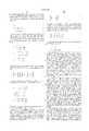
- the following mathematical treatmentuses rotations around Cartesian coordinate device X, Y and Z axes illustrated in FIGS. 6A-6C to determine the orientation of the DC accelerometers relative to the ideal X, Y and Z axes in the standing upright position.
- a coordinate frame shown by x, y and z axesis rotated in pitch around the x axis by an angle ⁇ x from the y axis towards the z axis to result in a new set of positioning axes denoted by x', y' and z' as shown in FIG. 6A.
- the original coordinate axes x, y and zcan be expressed in terms of new coordinate axes after the rotation as:
- rotation around the gravitational y axis by an angle ⁇ y from the z axis towards the x axis and rotation around z axis by an angle ⁇ z from the x axis towards the y axiscan be calculated and placed in matrix form resulting in inverse rotation matrices R x -1 , R y -1 and R z -1 as shown below: ##EQU1##
- the inverse rotation matrices R x -1 , R y -1 and R z -1relates the new coordinate axes x', y', z' to old coordinate axes x, y, z as: ##EQU2##
- equations (1)-(3)can be solved for x', y' and z' resulting in rotation matrices R x , R y and R z which are: ##EQU3## These rotation matrices relate the old coordinate axes x, y, z to the new coordinate axes x', y' and z'.
- Equation 7shows the general expression: ##EQU4## Since the posture is upright, a x and a z both equal 0, and a y is equal to 1 in the ideal case. Placing these accelerometer values in equation 7 and substituting in the values for R x , and R z matrices from equation (6), the following set of equations are obtained for ⁇ z and ⁇ x : ##EQU5##
- Equation (9)will result in four pairs of solutions which can then be tested against the third equation in equation (8) that has not been used so far to reduce the solution pairs to two.
- the Y accelerometerwill measure 0.966 g and the Z accelerometer will measure -0.259 g.
- the negative ⁇ xwould have determined the correct solution, while the minimum absolute sum of the angles would have determined the incorrect solution.
- the negative pitch angleis not always the correct determination.
- the determinationis not correct when the Y accelerometer measurement is negative.
- the negative pitch angle solution determinationassumes a pectoral implant site. For abdominal implants the minimum absolute sum of the angles or performing the full patient work-up would be preferred.
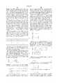
- the next stepwill be the utilization of pitch and roll angles to determine the correct posture of the patient for any arbitrary posture using the information given in Table II. This is performed by multiplying the acceleration measurement vector with inverse pitch matrix R x -1 and inverse roll matrix R z -1 to obtain corrected acceleration vector that can be compared against the ranges presented in Table II. This operation can be expressed as: ##EQU6## Substituting in the matrices for equation (4) into equation (10) yields the following corrected acceleration equations:
- the a x--meas , a y--meas , and a z--meas valuesare multiplied by a correction factor, e.g., the correction factors [cos( ⁇ y ) sin( ⁇ z )+sin( ⁇ x )sin( ⁇ y )cos( ⁇ z )], cos( ⁇ x )cos( ⁇ z ), and [sin( ⁇ y )sin( ⁇ z )+sin( ⁇ x )cos( ⁇ y )cos(.phi. z )], respectively, of equation (24), for example.
- the three correction factors for each equationcan be derived from the calculated pitch, yaw and roll angles ⁇ x , ⁇ y and ⁇ z .
- the pitch, yaw and roll angles ⁇ x , ⁇ y and ⁇ z and/or the correction factors used in equations (23)-(25)are stored in RAM 64 or RAM/ROM unit 68 to be used by the microprocessor 54 in performing equations (23)-(25) each time that the DC accelerometer output signals a x--meas , a y--meas and a z--meas are measured.
- the calculations of equations (23)-(25)can be performed using dedicated ICs in digital controller/timer circuit 40.
- a Matlab program that implements the algorithm with correction for roll, pitch and yawis set forth in the Appendix.
- the actual pitch and roll angles of the IMD device X, Y and Z axes from the ideal X, Y and Z axesare measured, and the yaw angle is either measured or assumed to be negligible.
- subsequent measured DC accelerometer output signals a x--meas , a y--meas and a z--meas in any arbitrary postureare corrected to a x--corr ,a y--corr and a z--corr using the correction factors and equations (23)-(25).
- the measurement of the DC accelerometer output signals a x--meas , a y--meas and a z--meas and the calculation of the corrected DC accelerometer output signals a x--corr , a y--corr and a z--corris preferably triggered in the manner described in detail in the above-incorporated '431 and '562 patents.
- the present inventioncontemplates the use of the same in other therapeutic devices for delivering other therapies and in monitoring devices for storing body position alone or in relation to other monitored parameters.
- the present inventionis also not limited to any particular pacing mode, and can function with prior art modes such as DDDR, AAIR, VVIR and DDIR.
- the detection of body position change from any body posture to any other body posture, such as from lying to an upright position or sitting to standing or standing to falling down to a horizontal orientation, for examples,may be used to set an appropriate transition pacing rate to treat syncopal patients susceptible to fainting.
- the multi-axis, solid state, DC accelerometer described above and depicted in the drawingscan be located in an IMD module that is physically separated from other IMD modules of a system as shown in the above-incorporated '404 patent.
- the IMD modulescan be tethered together by cables as shown in the '404 patent or can communicate with one another in a variety of manners including the manners described in commonly assigned U.S. Pat. No. 4,987,897, or as done by any other IMD's incorporated herein by reference.
Landscapes
- Health & Medical Sciences (AREA)
- Life Sciences & Earth Sciences (AREA)
- Cardiology (AREA)
- Heart & Thoracic Surgery (AREA)
- Animal Behavior & Ethology (AREA)
- Biophysics (AREA)
- Engineering & Computer Science (AREA)
- Biomedical Technology (AREA)
- Veterinary Medicine (AREA)
- Public Health (AREA)
- General Health & Medical Sciences (AREA)
- Physiology (AREA)
- Surgery (AREA)
- Molecular Biology (AREA)
- Medical Informatics (AREA)
- Physics & Mathematics (AREA)
- Pathology (AREA)
- Hematology (AREA)
- Nuclear Medicine, Radiotherapy & Molecular Imaging (AREA)
- Radiology & Medical Imaging (AREA)
- Dentistry (AREA)
- Oral & Maxillofacial Surgery (AREA)
- Measurement Of The Respiration, Hearing Ability, Form, And Blood Characteristics Of Living Organisms (AREA)
Abstract
Description
This invention relates to sensing orientation with respect to gravity and with respect to patient posture for implantable medical devices. In its most presently preferred form, the present invention relates to the use of an array of accelerometers that may be three, orthogonally sensitive DC accelerometers for detection of patient posture and activity level for medical monitoring and/or the delivery of device assisted therapies, such as cardiac pacing, drug delivery and the like, by an implantable medical device (IMD), and particularly to the calibration of the accelerometers to account for actual implantation orientation.
Commonly assigned U.S. Pat. Nos. 5,593,431 and 5,725,562, both incorporated herein by reference, set forth IMD systems for determining the physical posture of a patient's body, having a superior-inferior (S-I) body axis, an anterior-posterior (A-P) body axis and a lateral-medial (L-M) body axis, in relation to gravitational force imposed by earth's gravitational field. In certain embodiments, the IMDs disclosed therein have first, second and third DC accelerometers having sensitive axes mounted orthogonally within an IMD housing is adapted to be implanted with the sensitive axes generally aligned with the patient s body axes. Each DC accelerometer generates DC accelerometer signals having characteristic magnitudes and polarities on alignment of the sensitive axis with, against or normal to earth's gravitational field and DC accelerometer signals of varying magnitudes and polarities when not so aligned. Body position can be determined through comparison of the magnitudes and polarities of the DC accelerometer signals with the characteristic magnitudes and polarities. A patient activity signal may also be determined from the frequency of body movements recurring over a time unit effecting magnitude changes in the DC accelerometer signals within a certain range of magnitude and frequency. The activity and body position signals may be stored in a monitoring mode and/or used to effect the delivery of a therapy to the patient, e.g. by controlling the pacing rate of a rate responsive pacemaker or delivery of a drug or tachyarrhythmia therapy.
AC accelerometers may be used but are not preferred since they do not produce a signal directly relatable to gravity orientation.
Rate responsive pacing has been widely adopted for adjusting pacing rate to the physiologic needs of the patient in relatively recent years. The introduction of the Medtronic® Activitrax® pacemaker, embodying the invention of commonly assigned U.S. Pat. No. 4,428,378, provided patients with a pacing rate responsive capability dependent on the level of patient activity. A piezoelectric crystal bonded to the interior of the implantable pulse generator can or case is employed in that pacemaker and successor models to provide a pulse output signal related to the pressure wave generated by a patient's footfall and conducted through the body to the crystal. Thus, low frequency activity signals recurring at the patient's rate of walking or running could be sensed and processed to derive a pacing rate appropriate to the level of activity.
Activity sensor configurations employing integrated circuit, AC accelerometers on an IC chip inside the pacemaker are also being employed in the EXCEL VR pacemaker sold by Cardiac Pacemakers, Inc., and in similar rate responsive pacemakers sold by other manufacturers. The AC accelerometer is formed of a silicon beam mass suspended on the IC that swings or moves in response to shock waves caused by body motion and provides an output signal having a magnitude dependent on the rate of movement.
Like the piezoelectric crystal sensor, there is no signal output from the AC accelerometer in the absence of body motion and related to body position or attitude. In other words, when a patient is at rest, neither activity sensor provides any indication as to whether the patient is upright and awake and resting or lying down and presumably sleeping or resting. A lower sleep pacing rate than the rest pacing rate while awake and upright may be desirable for a given patient. Other sensors for sensing physiologic parameters induced by high levels of exercise have been proposed to detect the physiologic changes accompanying exercise, rest and sleep to trigger appropriate rates. Particularly, to lower the pacing rate during sleep, the inclusion of a real time clock to establish a Circadian rhythm pacing rate have also been proposed. None of these proposed sensors or systems are capable of determining a patient's position or posture.
A mechanical sensor has been proposed in the article "A New Mechanical Sensor for Detecting Body Activity and Posture, Suitable for Rate Responsive Pacing" by Alt et al. (PACE, Vol. 11, pp. 1875-81, November, 1988, Part II) and in U.S. Pat. No. 4,846,195 that involves use of a multi-contact, tilt switch. This switch employs a mercury ball within a container that is proposed to be fixed in the pulse generator case, so that if the pulse generator is implanted at a certain orientation, and stays in that orientation, certain contacts are closed by the mercury ball when the patient is upright and others are closed or none are closed when the patient is prostrate, i.e., either prone or supine. During movement of the body, the mercury ball is expected to jiggle randomly and the number of contacts made per unit of time may be used as a measure of the level of activity. Similar sensors have been proposed in U.S. Pat. Nos. 4,869,251, 5,010,893, 5,031,618 and 5,233,984, incorporated herein by reference.
In the commonly assigned '984 patent, a cubic shaped multi-axis position and activity sensor is employed in rate responsive pacing applications and in the detection of tachycardia based on the patient being supine and inactive. In the commonly assigned '618 patent, a single axis position sensor is employed that is employed to control the therapy delivered by a spinal cord stimulator. The sensors in both patents employ conductive liquids, including an electrolyte or elemental mercury.
The use of a solid state position sensor in the form of a DC accelerometer is proposed in U.S. Pat. Nos. 5,354,317 and 5,342,404, both incorporated herein by reference. The DC accelerometer in a preferred form as in these (and hereby incorporated in it's entireyt by this reference hereinto) and 404 patents, is fabricated in hybrid semiconductor IC form as a polycrystalline silicon, square plate, suspended at its four corners above a well in a single silicon crystal substrate, and associated low pass filter circuits are formed on the same substrate. The suspended plate structure moves between stationary positions with respect to the well on the suspension arms in response to gravitational force, depending on its orientation to the gravitational field. The plate also vibrates on the suspension arms similar to the AC accelerometer in response to acceleration movements of the patient's body.
Any type of accelerometer that can give a DC output that changes with its orientation or position sensitive to the earth's gravity would be useable. An example of a specific accelerometer type can be found in U.S. Pat. No. 5,345,824, assigned to Analog Devices, showing how a sensor with differential capacitive structure provides a signal output based on sensor orientation. Such a signal can be used to provide the DC signal useful for this invention.
In the pacing algorithms disclosed in the '317 patent, different base pacing rates are established depending on the static output of the position sensor that indicate the position of the patient, namely the upright, supine and prone positions, and separate base pacing rates can be set. Rate changes from the base pacing rates dependent on the exercise level of the patient in each position are suggested. Also, when changes in patient position are detected in the absence of physical exercise, the base pacing rate change is smoothed between the old and new rate to avoid a sudden step change.
The rate responsive pacemaker disclosed in the '317 patent offers some discrimination of patient position, but cannot distinguish among various patient positions where the suspended plate structure is aligned at the same angle to earth's gravitational field. The plane of the movable plate is at a fixed angle, e.g. coplanar, to a plane of the pulse generator case. Once the pulse generator is implanted in a patient, the movable plate plane may be aligned generally in parallel with the gravitational field and not detect the gravitational force (i.e., producing a zero amplitude output signal correlated to 0 g). The output of the so-aligned DC accelerometer would be the same whether a patient is standing, sitting or lying on either side, since the plate plane would remain in the same general parallel relationship to the gravitational field in all three positions. However, the pacing rates appropriate in standing, sitting or lying on a side are different when the patient is still.
In the above-incorporated '431 and '562 patents, the posture of the patient is determined through the use of two or more solid state, DC accelerometers mounted in mutual orthogonal relationship within the IMD housing. The two or more accelerometers develop two or more sets of accelerometer output signals having signal amplitudes and polarities that are dependent on the effect of gravity on the accelerometers. Threshold amplitudes are stored in IMD memory that are related to the posture of the patient while standing, sitting, or prostrate in supine, prone, left side and right side positions. The output signal amplitudes are compared to the stored threshold amplitudes, and the posture of the patient is determined from the closest comparison of the output signal amplitudes to he stored threshold amplitudes.
With three DC accelerometers mounted orthogonally, the patient's body posture at rest may be derived and employed, in a pacing context, to set physiologic resting pacing rates appropriate to the patient in each of the possible positions. The body posture may also be used to augment the diagnosis of a malignant tachyarrhythmia to trigger delivery of a cardioversion/defibrillation therapy and/or to be stored with other EGM and physiologic data related to a cardiac arrhythmia episode.
The orthogonally mounted, DC accelerometers are mounted into an IC chip, or to a hybrid circuit board, or otherwise orthogonally mounted so that the three sensitive axes are aligned with the three device positioning axes of the IMD housing that are designated as the X, Y and Z device positioning axes. In relation to a standing patient, these X, Y and Z device positioning axes correlate to L-M, S-I and A-P body axes, respectively, and the IMD case is preferably so marked for reference. The physician can implant and stabilize the IMD in the patient's thorax region so that the X, Y and Z positioning axes are aligned as closely as possible to the corresponding L-M, S-I, and A-P body axes of the patient's thorax. It is assumed that these body axes are aligned with the force of gravity when the patient is standing upright such that the S-I body axis is generally aligned in parallel with the force of gravity or an ideal Y-axis. Similarly, the A-P body axis and the L-M body axis are assumed to be generally aligned orthogonally to the force of gravity and are arbitrarily designated as the ideal Z-axis and ideal X-axis, respectively. The actual alignment of the device axes with the body axes depends on the selected implantation site, care taken during implantation to optimize the alignment, and the patient's anatomy at the implantation site.
Assuming that these device and body axes are aligned, a distinctive output signal amplitude is developed by each DC accelerometer in each patient posture due to the effect of gravity on the DC accelerometer sensitive axis in that posture. The posture of the patient can be derived from the comparison of the DC accelerometer output signal amplitudes with the stored threshold amplitudes as described above.
However, in practice, the implanted IMD housing is never perfectly aligned so that the sensitive axes of the three DC accelerometers are aligned optimally to the corresponding ideal device axes. Moreover, IMDs frequently migrate or are moved over time from the initial implant position even if the IMD housing is initially implanted in the proper orientation. Consequently, the magnitudes and polarities of the output signals of the three DC accelerometers can change with changed orientation of the IMD housing, rendering accurate determination of posture difficult and leading to miscalculation of posture in extreme cases.
These problems are generally recognized in the above-incorporated '431 and '562 patents, and a work-up routine is described to perform posture detection even though the device axes are not truly aligned with the ideal device axes. This is accomplished in the '431 patent by having the patient assume the standing, sitting, supine, prone, left side and right side resting positions to accumulate average output signals of each of the DC accelerometers in IMD. A programmer is employed to trigger the telemetry out of the accumulated sets of signals for external storage and display. Then, the deviations in the output signal amplitudes from a standard amplitude expected from alignment of the sensitive axis with earth's gravitational field may be derived and employed to normalize the actual output signals.
The normalization can be effected by transmitting correction factors to the IMD to be used to correct the actual accelerometer signal amplitudes or to adjust the threshold amplitudes that they are compared against, which is specifically described in the '431 patent. In the described calibration routine, sets of "posture confidence intervals" are calculated from the actual output signal amplitudes of the accelerometers and stored in the IMD memory as threshold amplitude ranges specific to each body position for comparison with the output signal amplitude of each accelerometer to determine the body position. This is a rather cumbersome procedure that may have to be repeated periodically over the life of the IMD to account for continued migration and reorientation of the device relative to the body.
It is suggested in the above-incorporated '317 patent that the output signal from the single DC accelerometer that is intended to be aligned with the S-I body axis or with the A-P body axis or the L-M body axis is calibrated at implantation to account for deviation of the accelerometer axis from the intended axis. In addition, it is suggested that an autocalibration routine be performed automatically from time to time when the patient is determined to be active. It is assumed that the patient is in an upright or standing stance when a certain level of exercise is detected that is consistent with walking or bicycling, for example.
The above-incorporated '404 patent describes use of two solid state accelerometers oriented at 90° to one another as an alternative to the preferred use of two mercury ball activity sensors aligned in the same manner. The sensors are aligned in the IMD so that the sensitive axis of one of the sensors will be implanted nominally in alignment with the gravitational Y-axis when the patient is in an upright posture. It is also suggested that a calibration routine be performed.
No particular calibration technique is described in either of the above-incorporated '404 or '317 patents. It appears that the sensor output signals are adjusted to account for the tilts in the sensors. In the above-incorporated '404 patent, it appears that the calibration may take place while the patient assumes the upright, supine and prone postures.
In view of the cumbersome procedure for calibrating the three orthogonal DC accelerometers, it would be preferable to simply determine the actual orientations of the X, Y and Z device axes to the corresponding X, Y and Z ideal axes from which highly accurate calibration factors can be determined to correct the actual output signal amplitudes and polarities.
In view of the above, it is an object of the present invention to provide a multi-axis, solid state position and activity sensor operable along at least two orthogonal sensitive axes calibrated for deviations from alignment to corresponding ideal axes to distinguish the posture or positioning attitude of the patient at rest and at levels of exercise.
It is a further an object of the present invention to employ such a sensor to record body position and activity signal levels derived from the output signals of such a sensor.
It is yet a further an object of the present invention to employ such a sensor to employ body position and activity signal levels derived from the output signals of such a sensor in controlling the delivery of a therapy to a patient.
In a specific context, it is an object of the present invention to provide a calibration routine that is either invoked automatically or in a patient work-up that determines the actual orientations of the sensitive axes of the sensor with respect to ideal axes.
It is yet another object of the present invention to provide a calibration routine in an IMD having such a sensor employing three orthogonally disposed DC accelerometers having three orthogonally disposed sensitive axes that is employed to determine the position of the IMD to the patient's body. In particular, it is an object of the invention to determine deviations of the sensitive axes from ideal X, Y and Z axes to determine the position of the IMD expressed in terms of pitch, roll and yaw angular deviations of the sensitive axes from ideal X, Y and Z axes.
Various other types of accelerometers that could be used with this invention are described by and in the background section of U.S. Pat. No. 5,780,742, hereby also incorporated by this reference. The calibration would have to be modified from what is taught herein as dictated by the choice of accelerometer, of course, but the same uses could be made of the data so derived, indicating deviations of the sensitive axes from the ideal, expressed in pitch, roll and yaw parameters.
These and other objects of the invention are realized in a method of and apparatus for determining the physical posture of a patient's body from corrected accelerometer output signals of three accelerometers having sensitive axes aligned to X, Y and Z device axes of an IMD housing implanted in the patient's body in relation to the X, Y and Z ideal axes, respectively. In the practice of the invention, at least the pitch and roll angles of the device axes from the gravitational axes are derived.
In one embodiment, an autocalibration routine is undertaken periodically using accelerometer DC signal data that is stored in a memory in the IMD while the patient is assumed to be upright and that assumes that the yaw angle is insignificant. This embodiment requires no supervisory physician intervention to occur. (If the number of indeterminate posture detections in a given period of time, a flag can be set to cause supervisory personnel to force a new full calibration as in the patient full work -up in the next mentioned embodiment). This autocalibration routine derives the actual device X-axis, Y-axis, and Z-axis with respect to the ideal X-axis, Y-axis, and Z-axis that is used to correct the accelerometer output signals for use in determining instantaneous or current patient posture. The pitch and roll angles or correction factors derived therefrom are averaged for use in the intervals between autocalibration events. One or more of the DC accelerometers can also be used to derive the level of patient activity from the number of changes in signal levels exceeding a certain threshold occurring in a given sampling time period, as is conventional in use of the piezoelectric and AC accelerometer activity sensors described above. The patient is assumed to be upright when an activity level consistent with walking for a specified time interval is determined from the output signals of the DC accelerometers.
In a further embodiment, a patient work-up is initiated from time to time following implantation wherein the patient assumes two orthogonal body positions, e.g. the upright and supine positions. In the full patient work-up routine, any rotation of the plane of the IMD housing defined by the device X-axis and the device Z-axis with respect to the ideal Y-axis resulting in a yaw angle of rotation is determined and taken into account along with the determination of the pitch and roll angles. In this way, any deviations in pitch, roll and yaw from the ideal alignment of the sensitive axes of the DC accelerometers with the ideal X, Y and Z ideal axes are accounted for. The determined pitch, roll and yaw angles and/or correction factors derived therefrom are maintained in IMD memory for use in correcting the measured DC accelerometer output signals between patient work-ups.
In both cases, the actual orientations of the sensitive axes of the DC accelerometers in the implanted IMD, corresponding to the X, Y and Z device axes, with respect to the ideal X. Y and Z axes are determined. Corrected DC accelerometer output signals are derived therefrom and are compared to a set of stored thresholds for each body posture to determine the actual body posture.
In accordance with the preferred embodiments of the invention, the stored posture and activity levels may be retained in a monitor and/or be employed to control the delivery of a variety of therapies, including pacing, cardioversion/defibrillation, other body stimulation therapies, and drug delivery therapies.
In the context of a pacemaker, the method and apparatus of the invention for pacing a patient's heart at a pacing rate dependent on patient activity and the physical posture of a patient's body, the determination of the actual implanted orientations of the mutually orthogonal DC accelerometers and their calibration to account for pitch, roll and yaw angles from the orthogonal ideal X, Y and Z axes in a computationally efficient manner increases the confidence of accuracy of the determination of patient posture. The autocalibration of the three orthogonal DC accelerometers utilizing accelerometer signals which have been stored in memory at a certain exercise level(s) when the patient is assumed to be standing upright overcomes the limitations of calibrating a single DC accelerometer. The incorporation of DC accelerometers in the IMD does not involve acceptance of unusual materials and technology. The calibrated mutually orthogonal DC accelerometers and associated circuits can most usefully be incorporated into a pacemaker pulse generator or other medical device.
By maintaining records of the posture of the patient and the deviation from ideal axes of the IMD's relative orientation to the ideal axes, the data in such records can be used to indicate orientation of a subcutaneous electrode array on the housing of an IMD which also has these accelerometers, to enhance electrogram records however they may be stored. The posture indicated can be used to enhance the rate responsiveness of pacemakers, for example switching from a pacing rate of 50 when a patient is sitting to a rate of 70 upon a clear indication of the patient moving to a standing position. Medical personal may better deal with patients with Orthostatic Hypotension from a record of the amount of time in standing, sitting, and supine positions, relative to significant events such as fainting or feeling faint, which an IMD having the invention can easily store. An IMD can provide rapid atrial and/or dual chamber pacing based on knowledge of when the patient is in an or relatively upright posture. Studies have shown increased pacing rates to be of benefit to some patients with severe postural hypotension, so there is a ready use for this type of posturally enhanced IMD. A physician can adapt therapy for such a patient based on such information. When combined with an indicator of sleep cycle, contemporaneous signals indicating that as patient sat up in bed may indicate a progression of heart failure as patients adapt to their lungs filling with fluid by sitting up during sleep. Together with monitoring heart rate drop, more effective support pacing (at high rates, for example) therapy for Vasovagal Syncope (VVS) can be supplied by a pacemaker that notices that a patient stood up contemporaneously with a rapid drop in heart rate. In addition, pacing therapies for vasovagal syncope, which sense sudden drops in heart rate could use body position as an additional input and withhold therapy when the patient in lying down or in a prostrate position. Symptomatic vasovagal syncope is rare during horizontal body positions but sudden heart rate drops are common during sleep leading to potentially numerous false positive indications and unneeded support pacing, drug or other therapy delivery. Therapies for sleep apnea may be created using posture information, and even patient compliance with exercise programs can be monitored using this information. Numerous other applications for these signals can be thought of and their use in research into the progression of heart disease is only one area.
These and other objects, advantages and features of the present invention will be more readily understood from the following detailed description of the preferred embodiments thereof, when considered in conjunction with the drawings, in which like reference numerals indicate identical structures throughout the several views, and wherein:
FIG. 1 is block level diagram of an exemplary IMD, namely a DDDR pacemaker, capable of implementing the mutually orthogonal DC accelerometers of the present invention as activity and patient posture sensors;
FIG. 2 is a schematic illustration of the X, Y and Z device axes of the sensitive axes of three DC accelerometers mounted orthogonally with respect to a hybrid circuit substrate within an IMD housing and correlated to S-I, L-M and A-P implantation markings on the IMD housing for orienting the IMD housing with the corresponding patient body axes and as closely as possible to the ideal X, Y and Z axes;
FIG. 3 is an illustration of the implantation of the IMD of FIG. 2 in a patient's body in substantial alignment with the S-I, L-M and A-P body axes and the ideal X, Y and Z axes;
FIG. 4 illustrates the IMD housing implanted in a typical thoracic location against the patient's ribcage and rotated about the ideal X-axis at a pitch angle showing the mis-alignment of the Y and Z device axes from the ideal Y and Z axes;
FIG. 5 illustrates the orientation of the IMD housing implanted in a typical thoracic location against the patient's ribcage and rotated about the ideal Z-axis at a roll angle showing the mis-alignment of the X and Y device axes from the ideal X and Y axes;
FIG. 5A illustrates the orientation of the IMD housing implanted in a thoracic location against the patient's ribcage and rotated about the ideal Y-axis at a yaw angle showing the mis-alignment of the X and Z device axes from the ideal X and Z axes.
FIGS. 6A-6C illustrate pitch angle, yaw angle, and roll angles of the sensitive axes of the DC accelerometers with respect to the ideal X-axis, Y-axis and Z-axis, respectively;
FIG. 7 is an operating algorithm for determining the patient's current posture from stored pitch, roll and yaw angles obtained in patient work-up or autocalibration modes;
FIG. 8 is a flow chart illustrating a patient work up in two orthogonal body positions to derive the actual orientation of the sensitive axes (or device axes) of the DC accelerometers with respect to the ideal X, Y and Z axes and correction factors from any detected pitch, roll, and yaw angles for use in deriving corrected accelerometer output signals for use in determining actual patient posture; and
FIG. 9 is a flow chart illustrating an autocalibration routine using accelerometer signal values collected while the patient is active and assumed to be upright and assuming no significant yaw angle to derive the actual orientation of the X, Y, and Z device axes with respect to the ideal X, Y and Z axes and correction factors for use in deriving corrected accelerometer output signals for use in determining patient posture.
The present invention is preferably implemented in any IMD and finds particular utility in the control of pacing rate to account for the level of patient activity and for patient posture and to discriminate between ascending and descending stairs as set forth in the specific embodiments of the above-incorporated '431 and '562 patents. It will also be understood that the present invention may be implemented in implantable tachyarrhythmia control pacemakers, cardioverters, defibrillators and the like. Specifically, the enhanced capability of determining body position may be employed to augment detection of life threatening cardiac arrhythmias that render a patient prostrate. Determination that a patient is upright and active vs. prostrate may be useful in distinguishing a malignant tachyarrythmia from an appropriate or sinus tachycardia.
Furthermore, the present invention may be employed in sleep disorder or apnea monitors to record the body position during episodes. Similarly, the body position may be used to verify that a patient is lying down and likely asleep during an assumed sleep period of a circadian rhythm monitor or to augment a circadian rhythm algorithm for a treatment device. The present invention may also find utility in providing patient position data correlated to the EGM and blood pressure in implantable cardiac EGM and hemodynamic monitors.
For purposes of illustration, the present invention will be described in the context of a multi-programmable DDDR pacemakers of types widely known in the prior art as described in the above-incorporated '431 and '562 patents. The illustrated IPG block diagram of FIG. 1 is merely exemplary of an IMD having components which can be used in the practice of the present invention. FIG. 1 corresponds to the general functional organization of most multi-programmable microprocessor controlled DDD(R) cardiac pacemakers presently commercially available. It is believed that the present invention is most readily practiced in the context of such a device, and that the present invention can therefore readily be practiced using the basic hardware of existing microprocessor controlled dual chamber pacemakers, as presently available, with the invention implemented primarily by means of modifications to the software stored in the ROM 66 of themicrocomputer circuit 34. However, the present invention may also be usefully practiced by means of a full custom integrated circuit, for example, a circuit taking the form of a state machine in which a state counter serves to control an arithmetic logic unit to perform calculations according to a prescribed sequence of counter controlled steps.
FIGS. 1-3 depict such an exemplary DDDR pacemaker pulse generator in an IMD housing 70 that is intended to be implanted in a patient's body 90 with a lead or leads 12, 14 extending into the patient'sheart 10. FIG. 2 is a schematic illustration of the solid state, X or L-M DC accelerometer 72, Y or S-I DC accelerometer 74, and Z or A-P DC accelerometer 76 mounted on the pulse generator hybrid circuit substrate 78 within IMD housing 70. The sensitive axes of DC accelerometers 72, 74 and 76 are orthogonally directed to one another and are aligned with the X, Y and Z device axes 82, 84, and 86. In relation to a standing patient, these X, Y and Z device axes 82, 84 and 86 correlate to S-I, L-M and A-P body axes, respectively, and the IMD housing 70 is so marked for reference. The physician can implant and stabilize the IMD in the patient's thorax region so that the X, Y and Z device axes are aligned as closely as possible to the corresponding S-I, A-P, and L-M body axes of the patient's thorax and the ideal X, Y and Z axes.
FIG. 1 is block level diagram of such a pacemaker implantable pulse generator orIPG 30 and lead set 12 and 14 which sets forth the structures required to incorporate the invention into a DDD/DDDR pacemaker. In the drawing, the patient'sheart 10 has anatrial pacing lead 12 passed into the right atrium and aventricular lead 14 passed into the right ventricle. Theatrial lead 12 has anatrial electrode array 16 which couples thepulse generator 30 to the atrium. Theventricular lead 14 has aventricular electrode array 18 for coupling thepulse generator 30 to the ventricle of the patient'sheart 10. Atrial and ventricular leads 12 and 14 are depicted as bipolar leads coupled to abipolar IPG 30, although unipolar leads could be employed with a suitable IPG.
TheIPG circuit 30 of FIG. 1 is divided generally into a pacing circuit 32 coupled to abattery power supply 50, anactivity sensor 60 of the type described below, atelemetry antenna 45 and amicrocomputer circuit 34. The pacing circuit 32 includes the atrial and ventricular output amplifier circuit 36 andsense amplifiers 38 that are coupled to the atrial and ventricular leads 12 and 14, respectively, the digital controller/timer circuit 40 and other associated components described below. The output circuit 36 andsense amplifier circuit 38 may contain atrial and ventricular pulse generators and sense amplifiers corresponding to any of those presently employed in commercially marketed dual chamber cardiac pacemakers.
Sensed atrial depolarizations (A-SENSE) or P-waves that are confirmed by the atrial sense amplifier are communicated to the digital controller/timer circuit 40 on the ASE line. Similarly, ventricular depolarizations (V-SENSE) or R-waves that are confirmed by the ventricular sense amplifier are communicated to the digital controller/timer circuit 40 on VSE. Thesensitivity control block 42 adjusts sensitivity of each sense amplifier in response to control signals provided by digital controller/timer 40 that are in turn stored in memory inmicrocomputer circuit 34.
In order to trigger generation of a ventricular pacing or VPE pulse, digital controller/timer circuit 40 generates a trigger signal on the V-trig line. Similarly, in order to trigger an atrial pacing or APE pulse, digital controller/timer circuit 40 generates a trigger pulse on A-trig line.
Crystal oscillator circuit 44 provides the basic timing clock for thepacing circuit 30, whilebattery 50 provides power. Reference mode circuit 48 generates stable voltage reference and current levels for the analog circuits within thepacing circuit 30 from the battery voltage and current. Power-on-reset circuit 46 responds to initial connection of thecircuit 30 to thebattery 50 for defining an initial operating condition and also resets the operating condition in response to detection of a low battery energy condition. Analog to digital converter (ADC) and multiplexor circuit 52 digitizes analog signals and voltage to provide real time telemetry of ASE and VSE cardiac signals fromsense amplifiers 38, for uplink transmission via RF transmitter and receiver circuit 47. Voltage reference and bias circuit 48, ADC and multiplexor 52, power-on-reset circuit 46 and crystal oscillator circuit 44 may correspond to any of those presently used in current marketed implantable cardiac pacemakers.
Data transmission to and from an external programmer (not shown, but see 100, FIG. 3) is accomplished by means of thetelemetry antenna 45 and the associated RF transmitter and receiver 47, which serves both to demodulate received downlink telemetry and to transmit uplink telemetry. Such transmissions may include particularly the orientation of the IMD as information either derived relative to ideal or in some less refined form, at a current time or pulled from memory as part of a histogram under control of the uplink program or more directly under control of the programmer. For example, circuitry for demodulating and decoding downlink telemetry may correspond to that disclosed in U.S. Pat. Nos. 4,556,063 and 4,257,423, while uplink telemetry functions may be provided according to U.S. Pat. No 4,374,382, all incorporated herein by reference. Uplink telemetry capabilities will typically include the ability to transmit stored digital information as well as real time or stored EGMs of atrial and/or ventricular electrical activity, as well as transmission of Marker Channel pulses indicating the occurrence of sensed and paced depolarizations in the atrium and ventricle.
Control of timing and other functions within thepacing circuit 30 is provided by digital controller/timer circuit 40 which includes a set of timers and associated logic circuits connected with themicrocomputer 34.Microcomputer 34 controls the operational functions of digital controller/timer 40, specifying which timing intervals are employed, and controlling the duration of the various timing intervals, via data and control bus 56.Microcomputer 34 contains a microprocessor 54, associated system clock 58, and on-processor RAM and ROM chips 64 and 66, respectively. In addition,microcomputer circuit 34 includes a separate RAM/ROM chip 68 to provide additional memory capacity. Microprocessor 54 is interrupt driven, operating in a reduced power consumption mode normally, and awakened in response to defined interrupt events, which may include the A-trig, V-trig, ASE and VSE signals. The specific values of the intervals defined are controlled by the microcomputer circuit 54 by means of data and control bus 56 from programmed-in parameter values and operating modes.
If the IPG is programmed to a rate responsive mode, the patient's activity level is monitored periodically, and the sensor derived pacing escape interval is adjusted proportionally. A timed interrupt, e.g., every two seconds, may be provided in order to allow the microprocessor 54 to analyze the output of the activity circuit (PAS) 62 and update the basic V-A escape interval employed in the pacing cycle. In the DDDR mode, using the microprocessor 54 controlled by a program in memory, the V-A escape interval may be selected as the variable pacing rate establishing interval, but the A-V interval and the atrial and ventricular refractory periods may also vary with the V-A escape interval established in response to patient activity.
Preferably two separate lower rate V-A interval timer functions are provided. The first is set by the physician when the base pacing rate is selected. This V-A time interval starts from the occurrence of a VPE or VPE, and provided neither an ASE nor a VSE occurs during the V-A time interval, an APE is generated after the expiration of the V-A time interval. The duration of the second lower rate time interval is a function of the measured patient activity acquired by theactivity sensor 21. Typically, the V-A time interval begins with a VSE or VPE and has a time duration reflecting patient activity. In this art, such structures are well known, and a variety of techniques can be used to implement the required timer functions.
Digital controller/timer circuit 40 starts and times out these and other intervals employed over a pacing cycle comprising a successive A-V and V-A interval in a manner well known in the art. Typically, digital controller/timer circuit 40 defines an atrial blanking interval following delivery of an atrial pacing pulse, during which atrial sensing is disabled, as well as ventricular blanking intervals following atrial and ventricular pacing pulse delivery, during which ventricular sensing is disabled. Digital controller/timer circuit 40 also defines the atrial refractory period (ARP) during which atrial sensing is disabled or the ASE is ignored for the purpose of resetting the V-A escape interval. The ARP extends from the beginning of the A-V interval following either an ASE or an A-trig and until a predetermined time following sensing of a ventricular depolarization or triggering the delivery of a VPE pulse. A post-ventricular atrial refractory period (PVARP) is also defined following delivery of a VPE pulse. The durations of the ARP, PVARP and VRP may also be selected as a programmable parameter stored in themicrocomputer 34. Digital controller/timer circuit 40 also controls the pulse widths of the APE and VPE pacing pulses and the sensitivity settings of thesense amplifiers 38 by means ofsensitivity control 42. Digital controller timer/logic circuit 40 also times out an upper rate limit interval (URL) set by a value programmed into memory inmicrocomputer circuit 34. This timer is initiated by the occurrence of a VPE or VSE, and limits the upper rate at which ventricular stimuli are delivered to the heart. The lower pacing rate is established by a programmed-in V-A or A--A interval value stored in memory inmicrocomputer circuit 34.
The illustrated IPG block diagram of FIG. 1 is merely exemplary, and corresponds to the general functional organization of most multi-programmable microprocessor controlled DDD(R) cardiac pacemakers presently commercially available. It is believed that the present invention is most readily practiced in the context of such a device, and that the present invention can therefore readily be practiced using the basic hardware of existing microprocessor controlled dual chamber pacemakers, as presently available, with the invention's program control being implemented primarily by means of modifications to the software stored in the likes of ROM 66 and/or RAM 64 and associated RAM/ROM unit 68 of themicrocomputer circuit 34. If the device were not a pacemaker, for example, as in an implantable hemodynamic monitor or electrocardiogram storage device as for example the Medtronic REVEAL(TM) or CHRONICLE(TM), no active therapy features (such as leads in the heartl2 and 14 to deliver stimulating pulses) would be needed to implement the invention and the data resulting from this invention would be stored for later transmission to indicate patient posture relative to other physiologic parameters the device may be tracking, like electrocardiogram or blood pressurefeatures in the two mentioned trade devices.
In accordance with one aspect of the present invention, the microcomputer also makes a determination of when the patient is walking from the output of the activity circuit (PAS) 62. The detection of walking is accomplished by an activity level that would drive the pacing rate to a programmed Activities of Daily Living (ADL) rate (i.e. a rate indicative of moderate exercise) which is sustained for more than ten seconds, for example.
Each of the DC accelerometers 72, 74, 76 depicted in FIG. 2 is preferably a surface micro-machined integrated circuit with signal conditioning, e.g. theModel ADXL 50 accelerometer sold by Analog Devices, Inc., Norwood Mass. and described in detail in the article "Airbags Boom When IC Accelerometer Sees 50G", in the Aug. 8, 1991, issue of Electronic Design, and in "Monolithic Accelerometer with Signal Conditioning", Rev. O, published by Analog Devices, Inc., both incorporated herein by reference in their entirety. Newer devices such as the ADXL05 and ADXL02, may be preferred for some embodiments, as could other models by other companies if it is more suitable for the IMD in which it will be used. (If using one of the accelerometer types discussed or mentioned in the summary section above, the ifollowing discussion will require modification to accomodate their particular types of output signals). Employing surface micro-machining, a set of movable capacitor plates are formed extending in a pattern from a shaped polysilicon proof mass suspended by tethers with respect to a further set of fixed polysilicon capacitor plates. The proof mass has a sensitive axis along which a force between 0 G and +/-50 G effects physical movement of the proof mass and a change in measured capacitance between the fixed and movable plates. The measured capacitance is transformed by the on-chip signal conditioning circuits into a low voltage signal.
The proof mass of theADXL 50 is coplanar with the IC chip plane it is tethered to for movement back and forth in positive and negative vector directions along a single sensitive axis. The planar orientation thus provides that the proof mass sensitive axis is along the length of the proof mass. For off the shelf use, theADXL 50 IC chip is mounted in a TO-5 can with the positive vector direction of the sensitive axis aligned to a reference tab of the can. By using the can tab, the positive or negative vector direction of the sensitive axis can be aligned with respect to some plane or angle of the system or circuit it is used in with respect to the constant vertical direction of gravitational force. The reference tabs for the three axes are schematically illustrated inactivity sensor 60 of FIG. 1 and with respect to each of the DC accelerometers 72, 74 and 76 of FIG. 2. In actual custom fabrication within thepulse generator 30, the DC accelerometers would be formed or assembled on a single IC chip and the assembly could be enclosed in a single IC package mounted to hybrid substrate 78. The assembly of the hybrid substrate 78 within the pulse generator housing 70 is precisely controlled to establish the orientations depicted in FIG. 2.
The effect of instantaneous or AC changes due to body motion acceleration can be measured by the voltage signal output level changes per unit time. As indicated in the above-incorporated publications, theADXL 50 can discriminate instantaneous acceleration levels up to 50 Gs, which is well in excess of the sensitivity required to detect patient footfalls regardless of the intensity level that a patient could muster. The output signal levels may be scaled to a lower range, e.g. 0 to ±2-5 G through adjustment of theinternal ADXL 50 buffer amplifier or custom fabrication.
FIG. 3 schematically illustrates the implantation of the pulse generator or IMD housing 70 so that the X, Y and Z device axes 82, 84, 86, are aligned as closely as possible with the patient's L-M, S-I, and A-P body axes 92, 94, 96, respectively. The A-P body or ideal Z-axis axis 96 and the device Z-axis 86 extend directly into the plane of FIG. 3. An external programmer 100 of the type described above communicates with the implantedpulse generator 30 through conventional two-way RF telemetry employing the antenna 102.
The effect of 1 G of gravitational force applied directly along the sensitive axis of astationary ADXL 50 accelerometer provides a characteristic output voltage signal having a level or amplitude that is referenced or scaled as +1 for angular computation purposes. The effect of 1 G of gravitational force applied in precisely the opposite or negative direction to the sensitive axis provides a characteristic output voltage signal amplitude that is referenced or scaled as -1. If the sensitive axis is oriented transversely to the direction of the gravitational force, a bias voltage level output signal should be present, and that voltage signal level is referenced or scaled as 0. The degree to which the sensitive axis is oriented away or tilted from the direction of the gravitational force can also be detected by the magnitude and polarity of the output voltage signal level deviating from the bias level scaled to 0 and below the output signal level values scaled to +1 and -1. The above-referenced publications provide instructions for scaling the voltage signal levels to the 0, +1 and -1 static level values. Other scales may be employed, depending on the signal polarities and ranges employed. A microprocessor interface circuit with autocalibration of offset error and drift (possibly caused by temperature variation or other things) may also be employed.
TABLE I ______________________________________ Posture a.sub.x a.sub.y a.sub.z ______________________________________UP 0 +1 0SUPINE 0 +1 PRONE 0 -1 RIGHT -1 0 LEFT +1 0 ______________________________________
Table I sets forth the ideal, scaled amplitudes of the output signals, ax, ay, and az, respectively, of the three DC accelerometers 72, 74 and 76 incorporated into an IMD housing 70 as depicted in FIG. 2. (The units in the ideal example would be in gravity or "g") The sensitive axis of DC accelerometer 74 is aligned to earth's gravitational field when thepulse generator 30 is implanted. Thus, when standing upright and remaining still, the amplitude or level of the output signal ay of the DC accelerometer 74 should be at +1. In this orientation, the scaled amplitudes of the output signals az and ax of the DC accelerometers 76 and 72, respectively, should approach 0.
The scaled amplitude of the output signal az of the DC accelerometer 76 should approach +1 or -1, respectively, when the patient lies still and supine or prone on his/her back or stomach and if the IMD housing 70 is implanted with the DC accelerometer 76 positive vector pointed anteriorly as shown in FIG. 3. In these positions, the amplitudes of the output signals ay and ax of the DC accelerometers 74 and 72, respectively, should approach 0. In the same fashion, the patient lying on the right and left sides will orient the sensitive axis of the DC accelerometer 72 with earth's gravitational field to develop the scaled amplitude of either -1 or +1 of the output signal ax. The amplitudes of the output signals ay and az of the DC accelerometers 74 and 76 should approach 0. In these ideal orientations of Table I, there is no rotation of the device axes of the IMD housing 70 with respect to earth's gravitational field.
The means and method for determining the physical posture of the patient operates through a comparison of the magnitudes and polarities of the output signals ax, ay, and az with thresholds that are selected as fractions of these +/-1 and 0 levels. It is recognized that the ideal orientation of the IMD housing 70 to achieve these output signal levels is seldom achieved. FIGS. 4, 5, and 5a illustrate implantation orientations of the IMD housing 70 that do not meet the ideal orientation to the ideal X-axis (Xideal -axis), Y-axis (Yideal -axis), and Z-axis (Zideal -axis). The angular orientations achieved at implant depend in part on the location where the IMD is implanted and sutured to the tissue under the skin in the thoracic region or lower in the abdominal region and the disposition of the attached leads or catheters, if used in the implanted system. Once implanted, the IMD typically maintains the orientation or slowly migrates or rotates either spontaneously or due to manipulation by the patient. Usually, these changes take place slowly, and so it is possible in accordance with the present invention to periodically determine the actual deviations of the device X, Y and Z axes from the ideal X, Y and Z axes and to use the deviation data to correct the DC accelerometer output signals or the thresholds that they are compared with in the determination of the patient's body posture.
In FIG. 4, the IMD housing is shown implanted in a typical thoracic location against the patient's ribcage at a pitch angle of -φx. The pitch angle -φx is the angular deviation of the Y and Z device axes from the ideal Y and Z axes due to the rotation of the IMD housing 70 about the device X-axis 82. The pitch angle φx of rotation about the device X-axis is also shown in FIG. 6A.
FIG. 5 illustrates the rotation of the IMD housing 70 about the A-P positioning axis 86 that results in a roll angle -φZ. The roll angle -φz is the angular deviation of the Y and X device axes from the ideal Y and X axes due to the rotation of the IMD housing 70 about the device Z-axis 86. The roll angle φz of rotation about the device Z-axis is also shown in FIG. 6C.
FIGS. 6A-6C illustrate the pitch angle φx, yaw angle φy and roll angle φz deviations of the actual DC accelerometer sensitive axes that correspond to the device X-axis (denoted x'), the device Y-axis (denoted y') and the device Z-axis (denoted z') with respect to the ideal X-axis, Y-axis and Z-axis, respectively, in the standing posture of the patient. The angular deviations illustrated in FIGS. 4 and 5 frequently occur together. However, the deviation in yaw angle φy of the device X-axis and Z-axis does not occur very frequently, and it often is insignificant. In the autocalibration routine of the present invention, it is assumed to be insignificant enough to ignore. In the full patient work-up routine, any rotation about the device Y-axis resulting in a yaw angle φy of rotation illustrated in FIG. 6B is determined and taken into account. In this way, any deviations in pitch, roll and yaw from the ideal alignment of the device axes of the DC accelerometers 72, 74 and 76 with the three gravitational axes are accounted for.
FIG. 7 depicts the steps of correcting measured tilt accelerations in the normal operating mode of the IMD operating algorithm as described in the context of the DDDR pacemaker of FIG. 1 in the above-incorporated '431 patent, for example. In step S100, the measured DC accelerometer output signals ax--meas, ay--meas, and az--meas are obtained while the patient is in the unknown posture. In step S102, the pitch angle φx, yaw angle φy and roll angle φz deviations previously stored in RAM following the patient work-up calibration routine of FIG. 8 or the autocalibration routine of FIG. 9 are retrieved from RAM and used in step S104 to calculate the corrected DC accelerometer output signals ax--corr, ay--corr, and az--corr using equations 23-25 described below.
In accordance with one aspect of the present invention illustrated in FIG. 8, the actual pitch angle φx, yaw angle φy and roll angle φz deviations are determined in a patient work-up of steps S200-S208. The pitch angle φx, yaw angle φy and roll angle φz deviations are stored in RAM in step S210 for use in correcting the amplitudes of the DC accelerometer output signals ax, ay and az in step S104 of FIG. 7. The patient work-up does not require the patient to assume all of the body postures or positions to store the actual DC accelerometer output signals ax, ay and az in each such position. It is only necessary for the patient to assume two orthogonal positions, e.g., the standing and supine positions or postures in steps to derive a set of standing DC accelerometer output signals ax ', ay ' and az ' and a set of supine DC accelerometer output signals ax ", ay " and az " in steps S202 and S206. The processing of these sets of signals in step S208 using equations 18-21 to derive the actual pitch angle φx, yaw angle φy and roll angle φz deviations is described further below.
In a further aspect of the present invention illustrated in FIG. 9, an autocalibration mode is entered into periodically, e.g., once a day, at step S308, to derive pitch angle φx and roll angle φz from sets of DC accelerometer output signals ax ', ay ' and az ' that are measured in step S304 and stored in IMD memory locations in step S306 while the patient is determined to be active in steps S300-S302. In the time period between the periodic calibration, and when the activity algorithm confirms that the patient is walking at steps S302 and S304 as described above with respect to FIG. 1, the patient is assumed to be in the standing body posture. Standing body posture sets of updated DC accelerometer output signals ax ', ay ' and az ' are then measured in step S304 and stored in memory locations in step S306. When the internal IMD real time clock (or one could use an indication of sleep such as long inactivity or some combination to provide the trigger) determines a time of day to conduct the autocalibration in step S308, the stored sets of updated DC accelerometer output signals ax ', ay ' and az ' are averaged in step S310. Alternatively, the DC accelerometer output signals ax ', ay ' and az ' are averaged as they are derived in step S304, and the averaged DC accelerometer output signals ax ', ay ' and az ' are stored in step S306. As noted above, the deviation in yaw angle φy of the device X and Z-axes from the ideal X-and Z- axes about the ideal Y-axis does not occur very frequently, and it is assumed to be insignificant enough to set to φy =0 in step S312. The pitch angle φx and roll angle φz deviations are derived from the averaged DC accelerometer output signals ax ', ay ' and az ' using equation 9 (described below) in step S310. The newly calculated pitch angle φx and roll angle φz are then stored in RAM in step S314. The stored pitch angle φx, yaw angle φy and roll angle φz and/or correction factors of equations (23)-(25) calculated therefrom as described below are then used in correcting the amplitudes of the measured DC accelerometer output signals ax, ay and az in step S104 of FIG. 7 using the equations (23)-(25) until the next calibration takes place.
Returning to FIG. 7, the corrected DC accelerometer output signals ax--corr ay--corr and az--corr are compared to a set of stored thresholds for each body posture to determine the actual body posture. The above-incorporated '431 patent describes a set of equations for deriving the patient's physical posture or position while at rest and while moving that is affected through a comparison of the magnitudes and polarities of the accelerometer output signals with these established thresholds. These thresholds and a further set of thresholds Ax, Ay, Az for a sitting position are summarized in Table II as follows:
TABLE II ______________________________________ Posture A.sub.x A.sub.y A.sub.z ______________________________________ UP <0.2 >0.8 <0.2 SIT -- >0.7 >0.2 SIT -- >0.7 <-0.2 SUPINE -- -- >0.8 PRONE -- -- <-0.8 RIGHT >0.8 -- -- LEFT <-0.8 -- -- ______________________________________
These thresholds can be programmable within the IMD and set to make the detection more or less sensitive to particular postures. In addition, it should be noted that combinations of measurements such as Ax of 0.7 and Az of 0.7 would indicate a posture between supine and lying on the right side. Since these postures are both lying type postures, they can be determined to be a class of postures indicating lying down rather than indeterminate position.
The following mathematical treatment uses rotations around Cartesian coordinate device X, Y and Z axes illustrated in FIGS. 6A-6C to determine the orientation of the DC accelerometers relative to the ideal X, Y and Z axes in the standing upright position. Assume a coordinate frame shown by x, y and z axes is rotated in pitch around the x axis by an angle φx from the y axis towards the z axis to result in a new set of positioning axes denoted by x', y' and z' as shown in FIG. 6A. The original coordinate axes x, y and z can be expressed in terms of new coordinate axes after the rotation as:
x=x' (1)
y=y' cos(φ.sub.x)-z'sin(φ.sub.x) (2)
z=y' sin(φ.sub.x)+cos(φ.sub.x) (3)
Similarly, rotation around the gravitational y axis by an angle φy from the z axis towards the x axis and rotation around z axis by an angle φz from the x axis towards the y axis can be calculated and placed in matrix form resulting in inverse rotation matrices Rx-1, Ry-1 and Rz-1 as shown below: ##EQU1##
The inverse rotation matrices Rx-1, Ry-1 and Rz-1 relates the new coordinate axes x', y', z' to old coordinate axes x, y, z as: ##EQU2##
Similarly, equations (1)-(3) can be solved for x', y' and z' resulting in rotation matrices Rx, Ry and Rz which are: ##EQU3## These rotation matrices relate the old coordinate axes x, y, z to the new coordinate axes x', y' and z'.
For the case where the IMD housing 70 deviates from its ideal position due to some roll and pitch angle but no yaw angle, then the resulting DC acceleration readings ax ', ay ' and az ' in the upright body posture can be expressed in terms of roll and pitch rotation matrices and ideal DC acceleration readings ax, ay and az in upright body posture.Equation 7 shows the general expression: ##EQU4## Since the posture is upright, ax and az both equal 0, and ay is equal to 1 in the ideal case. Placing these accelerometer values inequation 7 and substituting in the values for Rx, and Rz matrices from equation (6), the following set of equations are obtained for φz and φx : ##EQU5##
Solving the above equations (8) for the pitch angle φz and the roll angle φx yields;
φ.sub.z =arcsin(a.sub.x ') (9)
φ.sub.x =arccos(a.sub.y '/cos(φ.sub.z))
Equation (9) will result in four pairs of solutions which can then be tested against the third equation in equation (8) that has not been used so far to reduce the solution pairs to two. Two pairs of solutions are due to the inability to determine any yaw angle (rotation around Y-axis) since the gravitational vector (Y-axis) is perpendicular to the plane of rotation. For example when ax' =0, ay '=1 and az '=0, there is no roll and pitch angle, i.e., φz =0° and φx =0°. However, in the case where φz =180° and φx =180° the same acceleration readings will occur although the device X-axis and Z-axis end up in different locations in space. Therefore, some assumptions are necessary to pick one of the two solution pairs. A simple solution could be selecting the angles that result in a minimum of sum of absolute value of roll and pitch angles meaning that the smallest roll and pitch is more likely to occur.
An alternate method to the simple minimum sum of angles would be to utilize the polarity or sign of the Z axis accelerometer signal. This method will choose the pitch and roll angle solution, by choosing the pitch angle that is negative as the best solution. A brief explanation of the benefits of this method are presented. The anatomy of the upper pectoral region is concave and therefore the Z device axis will be tilted up as depicted in FIG. 4 and not perfectly normal to the earth's gravitational field. Therefore, the sign of the Z measurement will be positive and the pitch angle, φx, will be negative. However if one assumes the graphics side of the IMD is facing the skin of the patient in FIG. 4, then the case where the IMD is rotated so that the graphics side of the IMD is facing the interior of the body should be examined. In this case, since the device is rotated and the anatomy of the upper pectoral region is concave, the Z device axis will be tilted down. Therefore, the sign of the Z measurement will be negative, but the correct φx will still be negative.
The example below illustrates this solution: Consider the case where the graphics side is facing the skin and the upper pectoral tilt is 15 degrees and there is no roll of the device as nearly depicted in FIG. 4. For this case the Y accelerometer will measure 0.966 g and the Z accelerometer will measure 0.259 g. The two solutions for the pitch and roll are: [φx =-15, φz =0] or [φx =165, φz =-180]. The proper solution is [φx =-15, φz =0] and both the minimum sum of the angles and the negative φx solution determinations are correct. Next, consider the 2nd case where the graphics side facing the interior of the body (therefore rotated 180 degrees) and the upper pectoral tilt is 15 degrees. For this case the Y accelerometer will measure 0.966 g and the Z accelerometer will measure -0.259 g. The two solutions for the pitch and roll are: [φx =15, φz =0] or [φx =-165, φz =-180]. The correct solution is [φx =-165, φz =-180]. The negative φx would have determined the correct solution, while the minimum absolute sum of the angles would have determined the incorrect solution.
However, the negative pitch angle is not always the correct determination. The determination is not correct when the Y accelerometer measurement is negative. In this case, the pitch angle should always be positive. Therefore for the examples above if the Y accelerometer is measuring negative values, so the measurements are -0.966 g for the Y accelerometer and 0.259 g for the Z accelerometer, the correct solution is [x=15, z=-180] and for the case where Y accelerometer measures -0.966 g and the Z accelerometer measures -0.259 g, the correct solution is [x=-165, z=-180].
The table below shows the correct determination of the pitch angle polarity based on the Y and Z accelerometer polarity. Once the solution with the correct pitch angle polarity is chosen, the corresponding roll angle of the solution is also correct. Likewise, the magnitudes of the pitch and roll angle solutions will be correct.
______________________________________ ay az x ______________________________________ + + - + - - - + + - - + ______________________________________
The negative pitch angle solution determination assumes a pectoral implant site. For abdominal implants the minimum absolute sum of the angles or performing the full patient work-up would be preferred.
The next step will be the utilization of pitch and roll angles to determine the correct posture of the patient for any arbitrary posture using the information given in Table II. This is performed by multiplying the acceleration measurement vector with inverse pitch matrix Rx-1 and inverse roll matrix Rz-1 to obtain corrected acceleration vector that can be compared against the ranges presented in Table II. This operation can be expressed as: ##EQU6## Substituting in the matrices for equation (4) into equation (10) yields the following corrected acceleration equations:
a.sub.x--corr =cos(φ.sub.z)a.sub.x--meas -cos(φ.sub.x)sin(φ.sub.z) a.sub.y--meas +sin(φ.sub.x)sin(φ.sub.z) a.sub.z--meas (11)
a.sub.y--corr =sin(φ.sub.z)a.sub.x--meas +cos(φ.sub.x)cos(φ.sub.z)a.sub.y--meas -sin(φ.sub.x)cos (φ.sub.z) a.sub.z--meas (12)
a.sub.z--corr =sin(φ.sub.x)a.sub.y--meas +cos(φ.sub.x)a.sub.z--meas(13)
(Of course, in an IMD it would be preferred to use and store the correction factors to simplify the computations and make the processing more efficient. For example, for equation (11), cos(φz) could be stored during calibration as correction factor A, cos(φx) sin(φz) as correction factor B and so forth. This technique is useful for equations (11)-(13) and (25)-(27), where the IMD would be recalculating these often, as in for each posture determination).
If there is a yaw angle, the posture determined using the method described above could be incorrect. However, if the yaw angle is reasonably small, these simpler equations may be used for automatically correcting for the orientation.
A more accurate method of calibration that takes yaw angle into account involves using two sets of DC accelerometer output signals as noted above. The two orthogonal body postures are preferably the upright posture and the prone or supine body posture. The DC accelerometer output signals derived in the upright posture are denoted as ax ', ay ' and az ' whereas the DC accelerometer output signals derived in the supine posture are denoted as ax ", ay " and az ". If it is assumed that IMD housing 70 is moved away from its ideal position in alignment with the gravitational X-axis, Y-axis and Z-axis due to a combination of roll, pitch and yaw by angles φz, φx and φy, then: ##EQU7## Equation (14) is for the upright body position case, where ay =1, ax =0, and az =0 in the ideal case. Equation (15) is for the supine body position, az =1, ax =0, and ay =0. When the multiplication of three rotation matrices is carried out using equation (4), equations (14) and (15) can be expanded as: ##EQU8##
Then, two solutions for the pitch angle, φx within 0 to 360° can be obtained from:
φ.sub.x =arcsin(a.sub.y ") (18)
Similarly, for each φx, a solution for φy can be obtained matching the solutions from two equations below:
φ.sub.y =arcsin(-a.sub.x "/cos(φ.sub.x)) (19)
φ.sub.y =arccos(a.sub.z "/cos(φ.sub.x)) (20)
Similarly, φz can be calculated from equation (16):
φ.sub.z =arccos(ay'/cos(φ.sub.x)) (21)
Now, there are four triplets of solutions for φx, φy and φz which can be reduced to a single solution by using the remaining two equations in equation (16) to test the triplets. Once the pitch, yaw and roll angles φx, φy and φz are calculated, subsequent measured DC accelerometer output signals ax--meas, ay--meas and az--meas in any arbitrary posture can be corrected to ax--corr, ay--corr and az--corr by applying inverse rotation transformation using the calibration rotation angles: ##EQU9## which can be expanded as:
a.sub.x--corr =a.sub.x--meas [cos(φ.sub.y)cos(φ.sub.z)-cos(φ.sub.x)sin(φ.sub.y)sin(.phi..sub.z)]-a.sub.y--meas cos(φ.sub.x)sin(φ.sub.z)+a.sub.z--meas [sin(φ.sub.y)cos(φ.sub.z)+sin(φ.sub.x)cos(φ.sub.y)sin(.phi..sub.z) (23)
a.sub.y--corr =a.sub.x--meas [cos(φ.sub.y)sin(φ.sub.z)+sin(φ.sub.x)sin(φ.sub.y)cos(.phi..sub.z)+a.sub.y--meas cos(φ.sub.x)cos(φ.sub.z)+a.sub.z--meas [sin(φ.sub.y)sin(φ.sub.z)+sin(φ.sub.x)cos(φ.sub.y)cos(.phi..sub.z)] (24)
a.sub.z--corr =-a.sub.x--meas [cos(φ.sub.x)sin(φ.sub.y)]-a.sub.y--meas sin(φ.sub.x)+a.sub.z--meas cos(φ.sub.x)cos(φ.sub.y)(25)
In each of the equations (23)-(25), the ax--meas, ay--meas, and az--meas values are multiplied by a correction factor, e.g., the correction factors [cos(φy) sin(φz)+sin(φx)sin(φy)cos(φz)], cos(φx)cos(φz), and [sin(φy)sin(φz)+sin(φx)cos(φy)cos(.phi.z)], respectively, of equation (24), for example. The three correction factors for each equation can be derived from the calculated pitch, yaw and roll angles φx, φy and φz.
In the IMD architecture of the exemplary DDDR pacemaker circuit of FIG. 1, the pitch, yaw and roll angles φx, φy and φz and/or the correction factors used in equations (23)-(25) are stored in RAM 64 or RAM/ROM unit 68 to be used by the microprocessor 54 in performing equations (23)-(25) each time that the DC accelerometer output signals ax--meas, ay--meas and az--meas are measured. Alternatively, the calculations of equations (23)-(25) can be performed using dedicated ICs in digital controller/timer circuit 40. A Matlab program that implements the algorithm with correction for roll, pitch and yaw is set forth in the Appendix.
Thus, in the two preferred calibration methods of the invention, the actual pitch and roll angles of the IMD device X, Y and Z axes from the ideal X, Y and Z axes are measured, and the yaw angle is either measured or assumed to be negligible. Then, subsequent measured DC accelerometer output signals ax--meas, ay--meas and az--meas in any arbitrary posture are corrected to ax--corr,ay--corr and az--corr using the correction factors and equations (23)-(25). The corrected signals ax--corr, ay--corr and az--corr are compared to the stored set of thresholds Ax, Ay, Az shown in Table II for each posture or position following the procedure set forth in the above-incorporated '431 patent, for example.
In this DDDR pacemaker embodiment, the measurement of the DC accelerometer output signals ax--meas, ay--meas and az--meas and the calculation of the corrected DC accelerometer output signals ax--corr, ay--corr and az--corr is preferably triggered in the manner described in detail in the above-incorporated '431 and '562 patents.
As noted above, although the use of the two or three DC accelerometers are described above in relation to the determination of body posture for selecting a pacing rate, it will be understood that the present invention contemplates the use of the same in other therapeutic devices for delivering other therapies and in monitoring devices for storing body position alone or in relation to other monitored parameters. The present invention is also not limited to any particular pacing mode, and can function with prior art modes such as DDDR, AAIR, VVIR and DDIR. In addition, the detection of body position change from any body posture to any other body posture, such as from lying to an upright position or sitting to standing or standing to falling down to a horizontal orientation, for examples, may be used to set an appropriate transition pacing rate to treat syncopal patients susceptible to fainting.
It will be understood that the multi-axis, solid state, DC accelerometer described above and depicted in the drawings can be located in an IMD module that is physically separated from other IMD modules of a system as shown in the above-incorporated '404 patent. The IMD modules can be tethered together by cables as shown in the '404 patent or can communicate with one another in a variety of manners including the manners described in commonly assigned U.S. Pat. No. 4,987,897, or as done by any other IMD's incorporated herein by reference.
All such variations and modifications are intended to be within the scope of the invention claimed by this Letters Patent.
Claims (68)
1. A method of determining the physical posture of a patient's body, having an ideal Y axis, aligned with the superior-inferior body axis, an ideal Z axis aligned with the anterior-posterior body axis, and an ideal X axis aligned with the lateral-medial body said axis in relation to earth's gravitational field comprising the steps of:
implanting a multi-axis, solid state sensor in the patient's body, said solid state sensor comprising X, Y, and Z accelerometers having X, Y, and Z device axes, respectively, orthogonally disposed to one another, which provide X, Y, and Z accelerometer output signals, respectively, of a magnitude and polarity dependent on the degree of alignment of the respective axis with earth's gravitational field;
in a calibration mode following implantation:
measuring a first set of accelerometer output signals from said X, Y, and Z accelerometers while the patient is in a first body posture;
measuring a second set of accelerometer output signals from said X, Y, and Z accelerometers while the patient is in a second body posture orthogonal to said first body posture;
from said first and second sets of accelerometer output signals, deriving a pitch angle of the Y and Z device axes from the Y ideal axis and the Z ideal axis, respectively, due to rotation of the Y and Z device axes about the X device axis;
from said X and Z sets of accelerometer output signals, deriving a yaw angle of the X and Z device axes from the X ideal axis and the Z ideal axis, respectively, due to rotation of the X and Z device axes about the Y device axis; and
from said X and Y sets of accelerometer output signals, deriving a roll angle of the X and Y device axes from the X ideal axis and the Y ideal axis, respectively, due to rotation of the X and Y device axes about the Z device axis; and
in a normal operating mode, determining an unknown body posture of the patient by:
measuring the X, Y, and Z accelerometer output signals while the patient is in the unknown body posture;
correcting the measured X, Y, and Z accelerometer output signals employing the derived pitch, roll and yaw angles to derive corrected X, Y, and Z accelerometer output signals; and
determining the body posture of the patient employing the corrected X, Y, and Z accelerometer output signals.
2. The method of claim 1, further comprising the step of:
defining a set of X, Y, and Z thresholds for body postures that the patient can assume with respect to earth's gravitational field; and wherein the body posture determining step further comprises the steps of:
comparing the magnitudes and polarities of the corrected X, Y, and Z accelerometer output signals with the X, Y, and Z respective thresholds of each set of thresholds; and
determining the body posture of the patient most closely corresponding to the set of thresholds that is met by the X, Y, and Z corrected accelerometer output signals.
3. The method of claim 2, wherein the defining step further comprises the step of defining the sets of thresholds in relation to characteristic magnitudes and polarities of the accelerometer output signals on alignment of the device axes of the X, Y, and Z accelerometers with or normal to earth's gravitational field in each body posture.
4. The method of claim 2, wherein the defining step further comprises the step of defining the sets of thresholds in relation to characteristic magnitudes and polarities of the accelerometer output signals on alignment of the device axes of the X, Y, and Z accelerometers with or normal to earth's gravitational field in each body posture, including the upright body posture while standing or walking or running, a sitting body posture, a supine body posture, a prone body posture and left and right side lying body postures.
5. The method of any of the claims 1-4, further comprising the step of storing said determined body posture of the patient.
6. The method of any of the claims 1-4, further comprising the step of delivering a treatment therapy to the patient having a treatment parameter dependent on the determined body posture.
7. The method of any of the claims 1-4, further comprising the steps of:
storing said determined body posture of the patient; and
delivering a treatment therapy to the patient having a treatment parameter dependent on the determined body posture.
8. The method of any of the claims 1-4, further comprising the steps of:
defining a characteristic activity magnitude of at least one of the first, second and third accelerometer output signals effected by body movement occurring within a predetermined frequency range signifying a threshold patient activity level; and
deriving an activity level signal from said at least one of the X, Y or Z accelerometer signals exceeding said characteristic activity magnitude over a predetermined time period.
9. The method of any of the claims 1-4, further comprising the steps of:
defining a characteristic activity magnitude of at least one of the X, Y, and Z accelerometer output signals effected by body movement occurring within a predetermined frequency range signifying a threshold patient activity level;
deriving an activity level signal from said at least one of the X, Y, or Z accelerometer signals exceeding said characteristic activity magnitude over a predetermined time period; and
delivering a treatment therapy to the patient having a treatment parameter dependent on the determined body posture and the activity level signal of the patient.
10. The method of any of the claims 1-4, further comprising the steps of:
defining a characteristic activity magnitude of at least one of the X, Y and Z accelerometer output signals effected by body movement occurring within a predetermined frequency range signifying a threshold patient activity level;
deriving an activity level signal from said at least one of the X, Y or Z accelerometer signals exceeding said characteristic activity magnitude over a predetermined time period; and
storing said determined body posture and activity level of the patient.
11. The method of any of the claims 1-4 wherein the device's ideal axes are nominally defined as having orthogonal axes comprising a ideal Y-axis aligned with the superior-inferior body axis and aligned with earth's gravitational field, so as to measure 1 g of acceleration when the patient is in an upright body posture, a ideal X-axis normal to the ideal Y-axis aligned with the lateral-medial body axis and orthogonal to the earth's gravitational field, so as to measure 0 g of acceleration when the patient is in an upright body posture, and an ideal Z-axis normal to the ideal X-axis and the ideal Y-axis and aligned to the anterior-posterior body axis and orthogonal to the earth's gravitational field, so as to measure 0 g of acceleration when the patient is in an upright body posture, and wherein:
said implanting step further comprises implanting said multi-axis, solid state sensor in the patient's body so that the X device axis is nominally aligned with the lateral-medial body axis, the Y device axis is nominally aligned with the superior-inferior body axis, and the Z device axis is nominally aligned with the anterior-posterior body axis;
said step of measuring a first set of accelerometer output signals from said X, Y, and Z, and accelerometers is performed while the patient is in a first body posture wherein the ideal Y axis is nominally in alignment with the earth's gravitational field and ideal X and Z axes are nominally normal to the ideal Y-axis; and
said step of measuring a second set of accelerometer output signals from said X, Y, and Z accelerometers is performed while the patient is in a second body posture orthogonal to said first body posture wherein one of the X or Z ideal axes is nominally in alignment with the earth's gravitational field and the other of the X or Z ideal axes and the Y ideal axis are nominally normal to the earth's gravitational field.
12. The method of any of the preceding claims 1-4, wherein the first body posture is the upright standing body posture and the second body posture is a selected one of the supine body posture, prone body posture, left side lying body posture, and right side lying body posture.
13. A method of determining the physical posture of a patient's body, having a superior-inferior body axis or ideal Y axis, an anterior-posterior body axis or ideal Z axis and a lateral-medial body axis or ideal X axis, in relation to earth's gravitational field comprising the steps of:
implanting a multi-axis, solid state sensor in the patient's body, said solid state sensor comprising X, Y and Z DC accelerometers having X, Y and Z device axes, respectively, orthogonally disposed to one another, which provide X, Y and Z DC accelerometer output signals, respectively, of a magnitude and polarity dependent on the degree of alignment of the respective device axis with earth's gravitational field;
in a calibration mode following implantation:
determining that the patient is in an upright body posture wherein said ideal Y axis is nominally into alignment with earth's gravitational field and X and Z ideal axes are nominally normal to earth's gravitational field;
setting a yaw angle of the X and Z device axes from the ideal X or lateral-medial body axis and the ideal Z or anterior-posterior body axis, respectively, at a fixed value based on the assumption of minimal rotation of the X and Z device axes about the Y device axes after implantation;
measuring at least one set of DC accelerometer output signals from the X, Y, and Z DC accelerometers in the assumed upright body posture;
deriving a pitch angle of the Y and Z device axes from the ideal Y axis and the ideal Z axis, respectively, due to rotation of the Y and Z device axes a about the X device axis from the measured set of DC accelerometer output signals; and
deriving a roll angle of the X and Y device axes from the ideal X axis and the ideal Y axis, respectively, due to rotation of the X and Y device axes about the device Z axis from the measured set of DC accelerometer output signals; and
in a normal operating mode, determining an unknown posture of the patient by:
measuring the X, Y, and Z DC accelerometer output signals;
correcting the measured X, Y, and Z DC accelerometer output signals
employing the stored pitch, roll and yaw angles to derive corrected X, Y, and Z DC accelerometer output signals; and
determining the body posture of the patient employing the corrected X, Y, and Z DC accelerometer output signals.
14. The method of claim 13, further comprising the step of:
defining a set of X, Y, and Z thresholds for each body posture that the patient can assume with respect to the orthogonal ideal axes; and wherein the body posture determining step further comprises the steps of:
comparing the magnitudes and polarities of the corrected X, Y, and Z DC accelerometer output signals with the X, Y, and Z respective thresholds of each set of thresholds; and
determining the body posture of the patient corresponding to the set of thresholds that is met by the X, Y, and Z corrected DC accelerometer output signals.
15. The method of claim 14, wherein the defining step further comprises the step of defining the sets of thresholds in relation to characteristic magnitudes and polarities of the DC accelerometer output signals on alignment of the X, Y, and Z DC accelerometers with or normal to earth's gravitational field in each body posture.
16. The method of claim 14, wherein the defining step further comprises the step of defining the sets of thresholds in relation to characteristic magnitudes and polarities of the DC accelerometer output signals on alignment of the sensitive axes of the X, Y, and Z DC accelerometers with or normal to earth's gravitational field in each body posture, including the upright body posture while standing or walking or running, a sitting body posture, a supine body posture, a prone body posture and left and right side lying body postures.
17. The method of any of the claims 13-16, further comprising the step of storing said determined body posture of the patient.
18. The method of any of the claims 13-16, further comprising the step of delivering a treatment therapy to the patient having a treatment parameter dependent on the determined body posture.
19. The method of any of the claims 13-16, further comprising the steps of:
storing said determined body posture of the patient; and
delivering a treatment therapy to the patient having a treatment parameter dependent on the determined body posture.
20. The method of any of the claims 13-16, wherein the step of determining that the patient is in an upright body posture further comprises the steps of:
defining a characteristic activity magnitude of at least one of the first, second and third DC accelerometer output signals effected by body movement occurring within a predetermined frequency range signifying a threshold patient activity level; and
deriving an activity level signal from said at least one of the first, second or third DC accelerometer signals exceeding said characteristic activity magnitude over a predetermined time period that is characteristic of the patient walking in an upright body posture.
21. The method of any of the claims 13-16, wherein:
the step of determining that the patient is in an upright body posture further comprises the steps of:
defining a characteristic activity magnitude of at least one of the X, Y, and Z DC accelerometer output signals effected by body movement occurring within a predetermined frequency range signifying that the patient is walking in an upright body posture; and
determining that the patient is walking when the current magnitude of at least one of the X, Y, and Z DC accelerometer output signals matches or exceeds the characteristic activity magnitude over a predetermined time period that is characteristic of the patient walking in an upright body posture; and
the step of measuring at least one set of DC accelerometer output signals from the X, Y, and Z DC accelerometers in the assumed upright body posture further comprises:
measuring a plurality of sets of DC accelerometer output signals from the X, Y, and Z DC accelerometers in the assumed upright body posture; and
averaging each set of measured DC accelerometer output signals from the X, Y, and Z DC accelerometers to derive an averaged set of DC accelerometer output signals.
22. The method of any of the claims 13-16, wherein:
the step of determining that the patient is in an upright body posture further comprises the steps of:
defining a characteristic activity magnitude of at least one of the X, Y, and Z DC accelerometer output signals effected by body movement occurring within a predetermined frequency range signifying that the patient is walking in an upright body posture; and
determining that the patient is walking when the current magnitude of at least one of the X, Y, and Z DC accelerometer output signals matches or exceeds the characteristic activity magnitude over a predetermined time period that is characteristic of the patient walking in an upright body posture;
the step of measuring a set of DC accelerometer output signals from the X, Y, and Z DC accelerometers in the assumed upright body posture further comprises:
measuring a plurality of sets of DC accelerometer output signals from the X, Y, and Z DC accelerometers in the assumed upright body posture; and
averaging each set of measured DC accelerometer output signals from the X, Y, and Z DC accelerometers to derive an averaged set of DC accelerometer output signals; and
the steps of deriving pitch angle and roll angle further comprise;
periodically deriving a pitch angle of the Y and Z device axes from the Y and Z ideal axis, respectively, due to rotation of the Y and Z device axes about the X device axis from the measured and averaged set of DC accelerometer output signals; and
periodically deriving a roll angle of the X and Y device axes from the X and Y ideal axes, respectively, due to rotation of the X and Y device axes about the Z device axis from the measured and averaged set of DC accelerometer output signals.
23. The method of any of the claims 13-16, further comprising the steps of:
defining a characteristic activity magnitude of at least one of the X, Y, and Z DC accelerometer output signals effected by body movement occurring within a predetermined frequency range signifying a threshold patient activity level; and
deriving an activity level signal from said at least one of the X, Y and Z DC accelerometer signals exceeding said characteristic activity magnitude over a predetermined time period.
24. The method of any of the claims 13-16, further comprising the steps of:
defining a characteristic activity magnitude of at least one of the X, Y and Z DC accelerometer output signals effected by body movement occurring within a predetermined frequency range signifying a threshold patient activity level;
deriving an activity level signal from said at least one of the X, Y and Z DC accelerometer signals exceeding said characteristic activity magnitude over a predetermined time period; and
delivering a treatment therapy to the patient having a treatment parameter dependent on the determined body posture and the activity level signal of the patient.
25. The method of any of the claims 13-16, further comprising the steps of:
defining a characteristic activity magnitude of at least one of the first, X, Y and Z DC accelerometer output signals effected by body movement occurring within a predetermined frequency range signifying a threshold patient activity level;
deriving an activity level signal from said at least one of the X, Y and Z DC accelerometer signals exceeding said characteristic activity magnitude over a predetermined time period; and
storing said determined body posture and activity level of the patient.
26. The method of any of an claims 13-16 wherein the ideal coordinate system is nominally defined as having ideal axes comprising a ideal Y-axis aligned to earth's gravitational field, nominally aligned with the superior-inferior body axis, so as to measure 1 g of acceleration when the patient is in an upright body posture, an ideal X-axis normal to the ideal Y-axis and nominally aligned with the lateral-medial body axis, so as to measure 0 g of acceleration when the patient is in an upright body posture, and an ideal Z-axis normal to the ideal X-axis and the ideal Y-axis and nominally aligned to the anterior-posterior body axis, so as to measure 0 g of acceleration when the patient is in an upright body posture, and wherein:
said implanting step further comprises implanting said multi-axis, solid state sensor in the patient's body so that the X device axis is nominally aligned with the lateral-medial body axis, the Y device sensitive axis is nominally aligned with the superior-inferior body axis, and the Z device axis is nominally aligned with the anterior-posterior body axis; and
said step of measuring a set of DC accelerometer output signals from said X, Y and Z DC accelerometers is performed while the patient is in an assumed upright body posture such that the Y device axis is nominally in alignment with the earth's gravitational field and the X and Z device axes are nominally normal to the earth's gravitational field.
27. In an implantable medical device, a system for determining the body posture of a patient's body having an ideal Y axis aligned with the superior-inferior body axis, an ideal Z axis aligned with the anterior-posterior body axis and an ideal X axis aligned with lateral-medial body axis, in relation to earth's gravitational field comprising:
a multi-axis, solid state sensor, comprising X, Y and Z DC accelerometers having X, Y and Z device axes, respectively, orthogonally disposed to one another, which provide X, Y and Z DC accelerometer output signals, respectively, of a magnitude and polarity dependent on the degree of alignment of the respective device axis with earth's gravitational field, the multi-axis, solid state sensor associated with the implantable medical device and adapted to be implanted in the patient's body so that the X device axis is nominally aligned with the lateral-medial body axis, the Y device axis is nominally aligned with the superior-inferior body axis, and the Z device axis is nominally aligned with the anterior-posterior body axis;
means for correcting for deviations in alignment of the X device axis from the ideal X axis or lateral-medial body axis, the Y device axis from the ideal Y axis or superior-inferior body axis, and the Z device axis from the ideal Z axis or anterior-posterior body axis following implantation of the medical device comprising:
means for measuring a first set of DC accelerometer output signals from said X, Y and Z DC accelerometers while the patient is in a first body posture such that the Y device axis is nominally in alignment with earth's gravitational field and the X and Z device axes are nominally normal to earth's gravitational field;
means for measuring a second set of DC accelerometer output signals from said X, Y and Z DC accelerometers while the patient is in a second body posture orthogonal to said first body posture wherein one of the X or Z device axes is generally in alignment with earth's gravitational field and the other of the X and Z device axes and the Y device axis are nominally normal to earth's gravitational field;
means for deriving a pitch angle of the Y and Z device axes from the Y and Z ideal axis respectively, due to rotation of the Y and Z device axes about the X device axis from said first and second sets of DC accelerometer output signals;
means for deriving a yaw angle of the X and Z device axes from the ideal X and Z axis, respectively, due to rotation of the X and Z device axes about the Y device axis from said first and second sets of DC accelerometer output signals; and
means for deriving a roll angle of the X and Y device axes from the ideal X and Y axis, respectively, due to rotation of the X and Y device axes about the Z device axis from said first and second sets of DC accelerometer output signals; and
in a normal operating mode, means operable for determining an unknown body posture of the patient comprising:
means for measuring the X, Y and Z DC accelerometer output signals while the patient is in the unknown body posture;
means for correcting the measured X, Y, and Z DC accelerometer output signals employing the derived pitch, roll and yaw angles to derive corrected X, Y and Z DC accelerometer output signals; and
means for determining the body posture of the patient employing the corrected X, Y and Z DC accelerometer output signals.
28. The system of claim 27, further comprising:
means for defining a set of X, Y, and Z thresholds for each body posture that the patient can assume with respect to earth's gravitational field; and wherein the body posture determining means further comprises:
means for comparing the magnitudes and polarities of the corrected X, Y and Z DC accelerometer output signals with the X, Y and Z respective thresholds of each set of thresholds; and
means for determining the body posture of the patient corresponding to the set of thresholds that is met by the X, Y and Z corrected DC accelerometer output signals.
29. The system of claim 27, wherein the defining means further comprises means for defining the sets of thresholds in relation to characteristic magnitudes and polarities of the DC accelerometer output signals on alignment of the device axes of the X, Y and Z DC accelerometers with or normal to earth's gravitational field in each body posture.
30. The system of claim 27, wherein the defining means further comprises means for defining the sets of thresholds in relation to characteristic magnitudes and polarities of the DC accelerometer output signals on alignment of the device axes of the X, Y and Z DC accelerometers with or normal to earth's gravitational field in each body posture, including the upright body posture while standing or walking or running, a sitting body posture, a supine body posture, a prone body posture and left and right side lying body postures.
31. The system of any of the claims 27-30, further comprising means for storing said determined body posture of the patient.
32. The system of any of the claims 27-30, further comprising means for delivering a treatment therapy to the patient having a treatment parameter dependent on the determined body posture.
33. The system of any of the claims 27-30, further comprising:
means for storing said determined body posture of the patient; and
means for delivering a treatment therapy to the patient having a treatment parameter dependent on the determined body posture.
34. The system of any of the claims 27-30, further comprising:
means for defining a characteristic activity magnitude of at least one of the X, Y and Z DC accelerometer output signals effected by body movement occurring within a predetermined frequency range signifying a threshold patient activity level;
means for deriving an activity level signal from said at least one of the X, Y or Z DC accelerometer signals exceeding said characteristic activity magnitude over a predetermined time period; and
means for delivering a treatment therapy to the patient having a treatment parameter dependent on the determined body posture and the activity level signal of the patient.
35. The system of any of the claims 27-30, further comprising:
means for defining a characteristic activity magnitude of at least one of the X, Y and Z DC accelerometer output signals effected by body movement occurring within a predetermined frequency range signifying a threshold patient activity level; and
means for deriving an activity level signal from said at least one of the X, Y or Z DC accelerometer signals exceeding said characteristic activity magnitude over a predetermined time period.
36. The system of any of the claims 27-30, further comprising:
means for defining a characteristic activity magnitude of at least one of the X, Y and Z DC accelerometer output signals effected by body movement occurring within a predetermined frequency range signifying a threshold patient activity level;
means for deriving an activity level signal from said at least one of the X, Y or Z DC accelerometer signals exceeding said characteristic activity magnitude over a predetermined time period; and
means for storing said determined body posture and activity level of the patient.
37. The system of any of the claims 27-30, wherein the first body posture is the upright standing body posture and the second body posture is a selected one of the supine body posture, prone body posture, left side lying body posture, and right side lying body posture.
38. The system of any of the claims 27-30 wherein the device's ideal axes are nominally defined as having orthogonal gravitational axes comprising an ideal Y-axis aligned with the superior-inferior body axis and aligned with the earth's gravitational field, so as to measure 1 g of acceleration when the patient is in an upright body posture, an ideal X-axis normal to the ideal Y-axis aligned with the lateral-medial body axis and orthogonal to the earth's gravitational field, so as to measure 0 g of acceleration when the patient is in an upright body posture, and an ideal Z-axis normal to the ideal X-axis and the ideal Y-axis and aligned to the anterior-posterior body axis and orthogonal to the earth's gravitational field, so as to measure 0 g of acceleration when the patient is in an upright body posture; and wherein the first body posture is the upright standing body posture and the second body posture is a selected one of the supine body posture, prone body posture, left side lying body posture, and right side lying body posture; wherein
said first set of DC accelerometer output signals from said X, Y and Z DC accelerometers is measured while the patient is in the upright standing body posture such that the Y device axis is nominally in alignment with the earth's gravitational field and the X and Z device axes are nominally normal to the earth's gravitational field; and
said second set of DC accelerometer output signals from said X, Y and Z DC accelerometers is performed while the patient is in a selected one of the supine body posture, prone body posture, left side lying body posture, and right side lying body posture wherein one of the X or Z device axes is generally in alignment with the earth's gravitational field and the other of the X or Z device axes and the Y device axis are nominally normal to the earth's gravitational field.
39. An implantable medical device employing a system of determining the body posture of a patient's body, having an ideal Y axis or superior-inferior body axis, an ideal Z axis or anterior-posterior body axis and an ideal X-axis or lateral-medial body axis, in relation to earth's gravitational field, comprising:
a multi-axis, solid state sensor, comprising X, Y and DC accelerometers having X, Y and Z device axes, respectively, orthogonally disposed to one another, which provide X, Y and Z DC accelerometer output signals, respectively, of a magnitude and polarity dependent on the degree of alignment of the respective device axis with earth's gravitational field, the multi-axis, solid state sensor associated with the implantable medical device and adapted to be implanted in the patient's body so that the X device axis is nominally aligned with the lateral-medial body axis,
means operable assuming a minimal deviation of the yaw angle or the rotation of the X and Z device axis around the Y device axis at the site of implantation for correcting for deviations in alignment of the actual device axes from the ideal device axes,
means for determining that the patient is in an upright body posture wherein said Y device axis is nominally aligned with earth's gravitational field and X and Z device axes are nominally normal to earth's gravitational field;
means for setting a yaw angle of the X and Z device axes from the ideal X and, respectively, at a fixed value based on the assumption of minimal rotation of the X and Z device axes around the Y device axis
means for measuring at least one set of DC accelerometer output signals from the X, Y, and Z DC accelerometers while the patient is in the assumed upright body posture;
means for deriving a pitch angle of the Y and Z device axes from the ideal Y and Z device respectively, due to rotation of the Y and Z device axes about the X device axis from the measured set of DC accelerometer output signals; and
means for deriving a roll angle of the X and Y device axes from the ideal X and Y axes, respectively, due to rotation of the X and Y device axes about the Z device axis from the measured set of DC accelerometer output signals; and
in a normal operating mode, means for determining an unknown posture of the patient comprising:
means for measuring the X, Y and Z DC accelerometer output signals;
means for correcting the measured X, Y and Z DC accelerometer output signals employing the stored pitch, roll and yaw angles to derive corrected X, Y and Z DC accelerometer output signals; and
means for determining the body posture of the patient employing the corrected X, Y and Z DC accelerometer output signals.
40. The system of claim 39, further comprising:
means for defining a set of X, Y and Z thresholds for each body posture that the patient can assume with respect to the orthogonal gravitational axes; and wherein the body posture determining means further comprises:
means for comparing the magnitudes and polarities of the corrected X, Y and Z DC accelerometer output signals with the X, Y and Z=respective thresholds of each set of thresholds; and
means for determining the body posture of the patient corresponding to the set of thresholds that is met by the X, Y and Z corrected DC accelerometer output signals.
41. The system of claim 39, wherein the defining means further comprises means for defining the sets of thresholds in relation to characteristic magnitudes and polarities of the DC accelerometer output signals on alignment of the device axes of the X, Y and Z DC accelerometers with or normal to earth's gravitational field in each body posture.
42. The system of claim 39, wherein the defining means further comprises means for defining the sets of thresholds in relation to characteristic magnitudes and polarities of the DC accelerometer output signals on alignment of the device axes of the X, Y and Z DC accelerometers with or normal to earth's gravitational field in each body posture, including the upright body posture while standing or walking or running, a sitting body posture, a supine body posture, a prone body posture and left and right side lying body postures.
43. The system of any of the claims 39-42, further comprising means for storing said determined body posture of the patient.
44. The system of any of the claims 39-42, further comprising means for delivering a treatment therapy to the patient having a treatment parameter dependent on the determined body posture.
45. The system of any of the claims 39-42, further comprising:
means for storing said determined body posture of the patient; and
means for delivering a treatment therapy to the patient having a treatment parameter dependent on the determined body posture.
46. The system of any of the claims 39-42, wherein means for determining that the patient is in an upright body posture further comprises:
means for defining a characteristic activity magnitude of at least one of the first, second and third DC accelerometer output signals effected by body movement occurring within a predetermined frequency range signifying a threshold patient activity level; and
means for deriving an activity level signal from said at least one of the first, second or third DC accelerometer signals exceeding said characteristic activity magnitude over a predetermined time period that is characteristic of the patient walking in an upright body posture.
47. The system of any of the claims 39-42, wherein:
the means for determining that the patient is in an upright body posture further comprises:
means for defining a characteristic activity magnitude of at least one of the first, second and third DC accelerometer output signals effected by body movement occurring within a predetermined frequency range signifying that the patient is walking in an upright body posture; and
means for determining that the patient is walking when the current magnitude of at least one of the X, Y and Z DC accelerometer output signals matches or exceeds the characteristic activity magnitude over a predetermined time period that is characteristic of the patient walking in an upright body posture; and
the means for measuring a set of DC accelerometer output signals from the X, Y and Z DC accelerometers in the assumed upright body posture is operable for measuring a plurality of sets of DC accelerometer output signals from the X, Y and Z DC accelerometers in the assumed upright body posture, and further comprises:
means for averaging each set of measured DC accelerometer output signals from the X, Y and Z DC accelerometers to derive an averaged set of DC accelerometer output signals.
48. The system of any of the claims 39-42, wherein:
the means for determining that the patient is in an upright body posture further comprises:
means for defining a characteristic activity magnitude of at least one of the X, Y and Z DC accelerometer output signals effected by body movement occurring within a predetermined frequency range signifying that the patient is walking in an upright body posture; and
means for determining that the patient is walking when the current magnitude of at least one of the X, Y and Z DC accelerometer output signals matches or exceeds the characteristic activity magnitude over a predetermined time period that is characteristic of the patient walking in an upright body posture;
the means for measuring a set of DC accelerometer output signals from the X, Y and Z DC accelerometers in the assumed upright body posture is operable for measuring a plurality of sets of DC accelerometer output signals from the X, Y and Z DC accelerometers in the assumed upright body posture, and further comprises:
means for averaging each set of measured DC accelerometer output signals from the X, Y and Z DC accelerometers to derive an averaged set of DC accelerometer output signals; and
the means for deriving pitch angle and roll angle further comprise;
means for periodically deriving a pitch angle of the Y and Z device axes from the ideal Y and Z axes, respectively, due to rotation of the Y and Z device axes about the X device axis from the measured and averaged set of DC accelerometer output signals; and
means for periodically deriving a roll angle of the X and Y device sensitive axes from the ideal X and Y device axes, respectively, due to rotation of the X and Y device axes about the Z device axis from the measured and averaged set of DC accelerometer output signals.
49. The system of any of the claims 39-42, further comprising:
means for defining a characteristic activity magnitude of at least one of the X, Y and Z DC accelerometer output signals effected by body movement occurring within a predetermined frequency range signifying a threshold patient activity level; and
means for deriving an activity level signal from said at least one of the X, Y or Z DC accelerometer signals exceeding said characteristic activity magnitude over a predetermined time period.
50. The system of any of the claims 39-42, further comprising:
means for defining a characteristic activity magnitude of at least one of the X, Y and Z DC accelerometer output signals effected by body movement occurring within a predetermined frequency range signifying a threshold patient activity level;
means for deriving an activity level signal from said at least one of the X, Y and Z DC accelerometer signals exceeding said characteristic activity magnitude over a predetermined time period; and
means for delivering a treatment therapy to the patient having a treatment parameter dependent on the determined body posture and the activity level signal of the patient.
51. The system of any of the claims 39-42, further comprising:
means for defining a characteristic activity magnitude of at least one of the X, Y and Z DC accelerometer output signals effected by body movement occurring within a predetermined frequency range signifying a threshold patient activity level;
means for deriving an activity level signal from said at least one of the X, Y or Z DC accelerometer signals exceeding said characteristic activity magnitude over a predetermined time period; and
means for storing said determined body posture and activity level of the patient.
52. The system of any of the claims 39-42 wherein an ideal coordinate system is nominally defined as having ideal axes comprising an ideal Y axis aligned with the superior-inferior body axis and aligned to the earth's gravitational field, so as to measure 1 g of acceleration when the patient is in an upright body posture, an ideal X-axis normal to the ideal Y-axis and nominally aligned with the lateral-medial body axis, so as to measure 0 g of acceleration when the patient is in an upright body posture, and an ideal Z-axis normal to the ideal X-axis and the ideal Y-axis and nominally aligned to the anterior-posterior body axis, so as to measure 0 g of acceleration when the patient is in an upright body posture, and wherein:
said multi-axis, solid state sensor is adapted to be implanted in the patient's body so that the X device axis is nominally aligned with the lateral-medial body axis, the Y device axis is nominally aligned with the superior-inferior body axis, and the Z device axis is nominally aligned with the anterior-posterior body axis; and
said means for measuring a set of DC accelerometer output signals from said, Y and Z DC accelerometers is operable while the patient is in an assumed upright body posture such that the Y device axis is nominally in alignment with the earth's gravitational field and the X and Z device axes are nominally normal to the earth's gravitational field.
53. A method of determining the physical posture of a patient's body, having an ideal Y axis, an Z axis, and an ideal X axis, in relation to earth's gravitational field comprising the steps of:
implanting a multi-axis, solid state sensor, comprising X, Y and Z DC accelerometers having X, Y and Z device axes, respectively, which respond to earth's gravitational field to provide X, Y and Z respective DC accelerometer signals of a magnitude and polarity dependent on the degree of alignment therewith, in the patient's body so that said X, Y and Z device axes are generally aligned with said lateral-medial, superior-inferior, and anterior-posterior body axes, respectively;
in a calibration mode wherein the patient is in at least one known or assumed body posture:
deriving a pitch angle of the Y and Z axes from the ideal Y and Z device axes respectively, due to rotation of the Y and Z device axes about the X device axis;
deriving a yaw angle of the X and Z device axes from the ideal X and Z axes, respectively, due to rotation of the X and Z device axes about the Y device axes; and
deriving a roll angle of the X and Y device axes from the ideal X and Y axes, respectively, due to rotation of the X and Y device axes about the Z device axis; and
in a normal operating mode:
measuring X, Y and Z measured DC accelerometer signals from said X, Y and Z DC accelerometers, respectively, in an unknown body posture that the patient assumes;
correcting the measured X, Y and Z DC accelerometer signals to compensate for derived pitch, roll and yaw angles resulting from mis-alignment of said X, Y and Z device axes with said ideal X, Y and axes, respectively; and
determining the body posture of the patient from the corrected X, Y and Z DC accelerometer signals.
54. The method of claim 53, wherein said correcting step further comprises the steps of:
calculating correction factors from the derived pitch angle, roll angle and yaw angle for correction of the measured corrected X, Y and Z DC accelerometer output signals in the correcting step.
55. The method of claim 53, wherein said correcting step further comprises the steps of:
calculating correction factors from the derived pitch angle, roll angle and yaw angle for correction of the measured corrected X, Y and Z DC accelerometer output signals in the correcting step; and
storing the correction factors for use in the correcting step for a time period until the next derivation of the pitch angle, roll angle and yaw angle and calculation of the correction factors.
56. The method of any of the claims 53-55, wherein the step of deriving the yaw angle comprises setting the yaw angle of the X and Z device axes from the ideal X and Z, respectively, at a fixed value based on the assumption of minimal rotation of X and Z device axes about the Y device axes.
57. The method of any of the claims 53-55, further comprising the step of:
defining a set of X, Y and Z thresholds for each body posture that the patient can assume with respect to the orthogonal gravitational axes from a first characteristic magnitude and polarity of said X, Y and Z DC accelerometer signals on alignment of the sensitive axes of said X, Y and Z DC accelerometers with earth's gravitational field, a second magnitude and polarity of said X, Y and Z DC accelerometer signals on alignment with the earth's gravitational field, and a third characteristic magnitude and polarity of said X, Y and Z DC accelerometer signals; and
wherein said determining step further comprises the steps of:
comparing the magnitudes and polarities of the X, Y and Z DC accelerometer output signals with X, Y and Z respective thresholds of each set of thresholds; and
determining the body posture of the patient corresponding to the set of thresholds that is met by the X, Y and Z corrected DC accelerometer output signals.
58. A method as set forth in any of claims 1-4 or 13-16 or 53-55 further comprising the step of storing posture related data over time.
59. A method as set forth in any of claims 1-4 or 13-16 or 53-55 further comprising the step of storing device orientation relative to ideal axes over time.
60. An implantable medical device having a system for determining the physical posture of a patient's body, having an ideal Y axis, an ideal Z axis and an ideal X axis, in relation to earth's gravitational field comprising:
a multi-axis, solid state sensor, comprising X, Y and Z DC accelerometers having X, Y and Z device axes, respectively, orthogonally disposed to one another, which provide X, Y and Z DC accelerometer output signals, respectively, of a magnitude and polarity dependent on the degree of alignment of the respective device axis with the earth's gravitational field, the multi-axis, solid state sensor associated with the implantable medical device and adapted to be implanted in the patient's body so that the X device axis is nominally aligned with the lateral-medial body axis, the Y device axis is nominally aligned with the superior-inferior body axis, and the Z device axis is nominally aligned with the anterior-posterior body axis;
means for correcting for deviations in alignment of the X device axis from the ideal X axis or lateral-medial body axis, the Y device axis from the ideal Y axis or superior-inferior body axis, and the Z device axis from the ideal Z axis or anterior-posterior body axis following implantation of the medical device comprising:
means operable in a calibration mode with the patient in at least one known or assumed body posture for deriving a pitch angle of the Y and Z device axes from the ideal Y and Z axes, respectively, due to rotation of the Y and Z device axes about the X device axis in the implantation step;
means operable in the calibration mode with the patient in at least one known or assumed body posture for deriving a yaw angle of the X and Z device axes from the ideal X and Z axes, respectively, due to rotation of the X and Z device axes about the Y device axis in the implantation step; and
means operable in the calibration mode with the patient in at least one known or assumed body posture for deriving a roll angle of the X and Y device axes from the ideal X and Y axes, respectively, due to rotation of the X and Y axes about the Z device axis in the implantation step;
means operable in a normal operating mode when the patient assumes an unknown body posture for deriving X, Y and Z measured DC accelerometer signals from said X, Y and Z DC accelerometers, respectively;
means for correcting the measured X, Y and Z DC accelerometer signals for determined pitch, roll and yaw angular deviations resulting from mis-alignment of said X, Y and Z device axes with said ideal X, Y and Z axes, respectively; and
means for determining the body posture of the patient from the corrected X, Y and Z DC accelerometer signals.
61. The system of claim 60, wherein said correcting means further comprises means for calculating correction factors from the derived pitch angle, roll angle and yaw angle for correction of the measured corrected X, Y and Z DC accelerometer output signals in the correcting step.
62. The system of claim 60, wherein said correcting means further comprises:
means for calculating correction factors from the derived pitch angle, roll angle and yaw angle for correction of the measured corrected X, Y and Z DC accelerometer output signals in the correcting step; and
means for storing the correction factors for use in the correcting step for a time period until the next derivation of the pitch angle, roll angle and yaw angle and calculation of the correction factors.
63. The system of any of the claims 60-62, wherein the yaw angle deriving means further comprises means for setting the yaw angle of the X and Z device axes from the ideal X and Z axes, respectively, at a fixed value based on the assumption of minimal rotation of X and Z device axes about the Y device axis.
64. The system of any of the claims 60-62, further comprising:
a set of X, Y and Z thresholds for each body posture that the patient can assume with respect to the orthogonal gravitational axes from a first characteristic magnitude and polarity of said X, Y and Z DC accelerometer signals on alignment of the sensitive axes of said X, Y and Z DC accelerometers with earth's gravitational field, a second magnitude and polarity of said X, Y and Z DC accelerometer signals on alignment against earth's gravitational field, and a third characteristic magnitude and polarity of said X, Y and Z DC accelerometer signals; and
wherein said determining means further comprises:
means for comparing the magnitudes and polarities of the corrected X, Y and Z DC accelerometer output signals with the X, Y and Z respective thresholds of each set of thresholds; and
means for determining the body posture of the patient corresponding to the set of thresholds that is met by the X, Y and Z corrected DC accelerometer output signals.
65. A device as set forth in any of claims 27-30 or 39-42 or 58-62 wherein a memory means is adapted to store posture related data derived from said accelerometer signals, taken over time, and having telemetry means for transmitting said posture related data to an external device.
66. A device as set forth in any of claims 27-30 or 39-42 or 58-62 wherein a memory means is adapted to store posture related data derived from said accelerometer signals, taken over time, and having program means for determining from a detection of heart rate drop and at least partly from said position signals whether a condition of vasovagal syncope is likely to occur and to cause a stimulation circuit to deliver pacing stimulation at a support rate if said determination is positive.
67. A device as set forth in any of claims 27-30 or 39-42 or 58-62 wherein a memory means is adapted to store posture related data derived from said accelerometer signals, taken over time, and having program means for determining at least partly from said signals whether a patient is in an upright position and if not, then preventing the delivery of support pacing for vasovagal syncope.
68. A device as set forth in any of claims 27-30 or 39-42 or 58-62 wherein a memory means is adapted to store posture related data derived from said accelerometer signals, taken over time, and having program means adapted to trigger support pacing stimulation to an orthostatic hypotensive patient's heart if the patient is determined to be going to an upright posture from said posture related data.
Priority Applications (4)
| Application Number | Priority Date | Filing Date | Title |
|---|---|---|---|
| US09/160,647US6044297A (en) | 1998-09-25 | 1998-09-25 | Posture and device orientation and calibration for implantable medical devices |
| PCT/US1999/022018WO2000018317A2 (en) | 1998-09-25 | 1999-09-22 | Posture and device orientation sensing and calibration for implantable medical devices |
| EP99951567AEP1115350B1 (en) | 1998-09-25 | 1999-09-22 | Posture and device orientation sensing and calibration for implantable medical devices |
| DE69910802TDE69910802T2 (en) | 1998-09-25 | 1999-09-22 | DETECTING AND CALIBRATING THE ORIENTATION OF BODY POSTURE AND DEVICE IN IMPLANTABLE MEDICAL DEVICES |
Applications Claiming Priority (1)
| Application Number | Priority Date | Filing Date | Title |
|---|---|---|---|
| US09/160,647US6044297A (en) | 1998-09-25 | 1998-09-25 | Posture and device orientation and calibration for implantable medical devices |
Publications (1)
| Publication Number | Publication Date |
|---|---|
| US6044297Atrue US6044297A (en) | 2000-03-28 |
Family
ID=22577783
Family Applications (1)
| Application Number | Title | Priority Date | Filing Date |
|---|---|---|---|
| US09/160,647Expired - LifetimeUS6044297A (en) | 1998-09-25 | 1998-09-25 | Posture and device orientation and calibration for implantable medical devices |
Country Status (4)
| Country | Link |
|---|---|
| US (1) | US6044297A (en) |
| EP (1) | EP1115350B1 (en) |
| DE (1) | DE69910802T2 (en) |
| WO (1) | WO2000018317A2 (en) |
Cited By (322)
| Publication number | Priority date | Publication date | Assignee | Title |
|---|---|---|---|---|
| US6188927B1 (en)* | 1999-04-16 | 2001-02-13 | Pacesetter, Inc. | Implantable cardiac stimulation system having improved method of calibrating physiologic sensors |
| US20020147476A1 (en)* | 2001-04-10 | 2002-10-10 | Daum Douglas R. | Cardiac rhythm management system adjusting rate response factor for treating hypotension |
| US6466821B1 (en)* | 1999-12-08 | 2002-10-15 | Pacesetter, Inc. | AC/DC multi-axis accelerometer for determining patient activity and body position |
| US6625492B2 (en) | 2000-05-15 | 2003-09-23 | Pacesetter, Inc. | Implantable cardiac stimulation device with detection and therapy for patients with vasovagal syncope |
| US6625493B2 (en) | 2001-08-24 | 2003-09-23 | Pacesetter, Inc. | Orientation of patient's position sensor using external field |
| US20030191503A1 (en)* | 2001-07-31 | 2003-10-09 | Cardiac Pacemakers, Inc. | Cardiac rhythm management system for edema |
| US20030204209A1 (en)* | 2002-04-26 | 2003-10-30 | Medtronic, Inc. | Method and apparatus for delaying a ventricular tachycardia therapy |
| US6647295B2 (en)* | 2000-05-15 | 2003-11-11 | Pacesetter, Inc. | Implantable cardiac stimulation device with detection and therapy for patients with vasovagal syncope |
| US6658292B2 (en)* | 2001-08-24 | 2003-12-02 | Pacesetter, Inc. | Detection of patient's position and activity status using 3D accelerometer-based position sensor |
| US20040073093A1 (en)* | 2002-10-11 | 2004-04-15 | Cardiac Pacemakers, Inc. | Methods and devices for detection of context when addressing a medical condition of a patient |
| US20040073262A1 (en)* | 2000-11-02 | 2004-04-15 | Cardiac Pacemakers, Inc. | Technique for discriminating between coordinated and uncoordinated cardiac rhythms |
| US20040073128A1 (en)* | 2002-10-09 | 2004-04-15 | Cardiac Pacemakers, Inc. | Detection of congestion from monitoring patient response to a recumbent position |
| US20040088016A1 (en)* | 2002-11-01 | 2004-05-06 | Daum Douglas R. | Rate-adaptive pacemaker with compensation for long-term variations in average exertion level |
| WO2004041086A1 (en)* | 2002-11-05 | 2004-05-21 | Philips Intellectual Property & Standards Gmbh | Accelerometer with an automatic calibration |
| US20040134496A1 (en)* | 2003-01-10 | 2004-07-15 | Cho Yong K. | Method and apparatus for detecting respiratory disturbances |
| US20040138648A1 (en)* | 2000-12-18 | 2004-07-15 | Cardiac Pacemakers, Inc. | Drug delivery system for implantable medical device |
| US20040158289A1 (en)* | 2002-11-30 | 2004-08-12 | Girouard Steven D. | Method and apparatus for cell and electrical therapy of living tissue |
| US20040158290A1 (en)* | 2002-11-30 | 2004-08-12 | Girouard Steven D. | Method and apparatus for cell and electrical therapy of living tissue |
| US20040193021A1 (en)* | 2002-12-11 | 2004-09-30 | Proteus Biomedical, Inc., A Delaware Corporation | Method and system for monitoring and treating hemodynamic parameters |
| US20050021098A1 (en)* | 2001-07-27 | 2005-01-27 | Cardiac Pacemakers, Inc. | Method and system for treatment of neurocardiogenic syncope |
| US20050027330A1 (en)* | 2003-07-31 | 2005-02-03 | Assaf Govari | Encapsulated sensor with external antenna |
| US20050043652A1 (en)* | 2003-08-18 | 2005-02-24 | Lovett Eric G. | Sleep state classification |
| US20050060001A1 (en)* | 2003-09-15 | 2005-03-17 | Ruchika Singhal | Automatic therapy adjustments |
| US20050061320A1 (en)* | 2003-09-18 | 2005-03-24 | Cardiac Pacemakers, Inc. | Coordinated use of respiratory and cardiac therapies for sleep disordered breathing |
| US20050065448A1 (en)* | 2003-09-18 | 2005-03-24 | Cardiac Pacemakers, Inc. | Methods and systems for assessing pulmonary disease |
| US20050065572A1 (en)* | 2003-09-18 | 2005-03-24 | Cardiac Pacemakers, Inc. | Diagnosis and/or therapy using blood chemistry/expired gas parameter analysis |
| US20050061323A1 (en)* | 2003-09-18 | 2005-03-24 | Cardiac Pacemakers, Inc. | Methods and systems for control of gas therapy |
| US20050074741A1 (en)* | 2003-09-18 | 2005-04-07 | Kent Lee | System and method for discrimination of central and obstructive disordered breathing events |
| US20050076909A1 (en)* | 2003-09-18 | 2005-04-14 | Stahmann Jeffrey E. | Synergistic use of medical devices for detecting medical disorders |
| US20050081847A1 (en)* | 2003-09-18 | 2005-04-21 | Kent Lee | Automatic activation of medical processes |
| US20050113710A1 (en)* | 2003-09-18 | 2005-05-26 | Stahmann Jeffrey E. | Implantable device employing movement sensing for detecting sleep-related disorders |
| US20050109339A1 (en)* | 2003-09-18 | 2005-05-26 | Stahmann Jeffrey E. | Respiratory therapy control based on cardiac cycle |
| US6912420B2 (en)* | 2001-04-10 | 2005-06-28 | Cardiac Pacemakers, Inc. | Cardiac rhythm management system for hypotension |
| US20050148897A1 (en)* | 2003-12-24 | 2005-07-07 | Cho Yong K. | Implantable medical device with sleep disordered breathing monitoring |
| US20050192507A1 (en)* | 2001-11-21 | 2005-09-01 | Cameron Health, Inc. | Multiple electrode vectors for implantable cardiac treatment devices |
| US20050209643A1 (en)* | 2004-03-16 | 2005-09-22 | Heruth Kenneth T | Controlling therapy based on sleep quality |
| US20050209645A1 (en)* | 2004-03-16 | 2005-09-22 | Heruth Kenneth T | Collecting posture information to evaluate therapy |
| US20050209513A1 (en)* | 2004-03-16 | 2005-09-22 | Heruth Kenneth T | Collecting sleep quality information via a medical device |
| US20050209511A1 (en)* | 2004-03-16 | 2005-09-22 | Heruth Kenneth T | Collecting activity and sleep quality information via a medical device |
| US20050209512A1 (en)* | 2004-03-16 | 2005-09-22 | Heruth Kenneth T | Detecting sleep |
| US20050209644A1 (en)* | 2004-03-16 | 2005-09-22 | Heruth Kenneth T | Collecting activity information to evaluate therapy |
| US20050216064A1 (en)* | 2004-03-16 | 2005-09-29 | Heruth Kenneth T | Sensitivity analysis for selecting therapy parameter sets |
| US20050245988A1 (en)* | 2004-04-14 | 2005-11-03 | Medtronic, Inc. | Collecting posture and activity information to evaluate therapy |
| US20050283197A1 (en)* | 2001-04-10 | 2005-12-22 | Daum Douglas R | Systems and methods for hypotension |
| US20060041280A1 (en)* | 2004-08-19 | 2006-02-23 | Cardiac Pacemakers, Inc. | Thoracic impedance detection with blood resistivity compensation |
| US20060052836A1 (en)* | 2004-09-08 | 2006-03-09 | Kim Daniel H | Neurostimulation system |
| US20060136028A1 (en)* | 2004-12-20 | 2006-06-22 | Jeffrey Ross | Epicardial patch including isolated extracellular matrix with pacing electrodes |
| US20060130838A1 (en)* | 2004-12-20 | 2006-06-22 | Lee Yong Y | Data logger for monitoring asthmatic conditions |
| FR2879432A1 (en)* | 2004-12-21 | 2006-06-23 | Ela Medical Soc Par Actions Si | Vasovagal syncope state non-invasive diagnosis apparatus, has signal processing and amplifying equipment and microcomputer to find syncope type, according to collected endocardiac acceleration values and heart rate |
| US20060161211A1 (en)* | 2004-12-31 | 2006-07-20 | Todd Thompson | Implantable accelerometer-based cardiac wall position detector |
| US20060173257A1 (en)* | 2005-01-31 | 2006-08-03 | Konica Minolta Sensing, Inc. | Sleep evaluation method, sleep evaluation system, operation program for sleep evaluation system, pulse oximeter, and sleep support system |
| US7089055B2 (en) | 2002-06-28 | 2006-08-08 | Cardiac Pacemakers, Inc. | Method and apparatus for delivering pre-shock defibrillation therapy |
| US20060212081A1 (en)* | 2003-07-10 | 2006-09-21 | Jms Co., Ltd. | Pacemaker system for treating sleep apnea syndrome |
| US20060224190A1 (en)* | 2005-04-05 | 2006-10-05 | Jong Gill | System and method for detecting heart failure and pulmonary edema based on ventricular end-diastolic pressure using an implantable medical device |
| US20060241513A1 (en)* | 2005-04-26 | 2006-10-26 | Cardiac Pacemakers, Inc. | Calibration of impedance monitoring of respiratory volumes using thoracic D.C. impedance |
| US20060253042A1 (en)* | 2005-05-04 | 2006-11-09 | Stahmann Jeffrey E | Syncope logbook and method of using same |
| US20060258952A1 (en)* | 2005-05-11 | 2006-11-16 | Cardiac Pacemakers, Inc. | Enhancements to the detection of pulmonary edema when using transthoracic impedance |
| US20060270939A1 (en)* | 2005-05-24 | 2006-11-30 | Cardiac Pacemakers, Inc. | Systems and methods for multi-axis cardiac vibration measurements |
| US7149579B1 (en) | 2002-12-23 | 2006-12-12 | Pacesetter, Inc. | System and method for determining patient posture based on 3-D trajectory using an implantable medical device |
| US7149584B1 (en) | 2002-12-23 | 2006-12-12 | Pacesetter, Inc. | System and method for determining patient posture based on 3-D trajectory using an implantable medical device |
| US20060282000A1 (en)* | 2005-06-08 | 2006-12-14 | Cardiac Pacemakers, Inc. | Ischemia detection using a heart sound sensor |
| US20070015976A1 (en)* | 2005-06-01 | 2007-01-18 | Medtronic, Inc. | Correlating a non-polysomnographic physiological parameter set with sleep states |
| US7171270B1 (en)* | 2003-12-29 | 2007-01-30 | Pacesetter, Inc. | Implantable cardiac device to promote intrinsic rhythm to alleviate orthostatic hypotension |
| US20070050597A1 (en)* | 2005-08-24 | 2007-03-01 | Nintendo Co., Ltd. | Game controller and game system |
| US20070049374A1 (en)* | 2005-08-30 | 2007-03-01 | Nintendo Co., Ltd. | Game system and storage medium having game program stored thereon |
| US20070073168A1 (en)* | 2005-09-16 | 2007-03-29 | Yi Zhang | Rapid shallow breathing detection for use in congestive heart failure status determination |
| US20070072680A1 (en)* | 2005-08-24 | 2007-03-29 | Nintendo Co., Ltd. | Game controller and game system |
| US20070118056A1 (en)* | 2005-11-18 | 2007-05-24 | Hua Wang | Posture detector calibration and use |
| US20070115277A1 (en)* | 2005-11-18 | 2007-05-24 | Hua Wang | Posture detection system |
| US7225023B1 (en)* | 1999-07-22 | 2007-05-29 | Pacesetter, Inc. | System and method for modulating the pacing rate based on patient activity and position |
| US20070123758A1 (en)* | 2004-03-16 | 2007-05-31 | Medtronic, Inc. | Determination of sleep quality for neurological disorders |
| US20070129622A1 (en)* | 2005-12-02 | 2007-06-07 | Medtronic, Inc. | Wearable ambulatory data recorder |
| US20070129641A1 (en)* | 2005-12-01 | 2007-06-07 | Sweeney Robert J | Posture estimation at transitions between states |
| US20070129643A1 (en)* | 2005-12-01 | 2007-06-07 | Jonathan Kwok | Method and system for heart failure status evaluation based on a disordered breathing index |
| US20070142868A1 (en)* | 2005-12-21 | 2007-06-21 | Moon Loell B | Posture sensor |
| US20070156057A1 (en)* | 2005-12-30 | 2007-07-05 | Cho Yong K | Method and system for interpreting hemodynamic data incorporating patient posture information |
| US20070154893A1 (en)* | 2005-12-29 | 2007-07-05 | Zhongping Yang | Implantable cell/tissue-based biosensing device |
| US20070161873A1 (en)* | 2002-12-04 | 2007-07-12 | Cardiac Pacemakers, Inc. | Sleep detection using an adjustable threshold |
| US20070161914A1 (en)* | 2003-01-24 | 2007-07-12 | Mark Zdeblick | Methods and systems for measuring cardiac parameters |
| US7248923B2 (en) | 2003-11-06 | 2007-07-24 | Cardiac Pacemakers, Inc. | Dual-use sensor for rate responsive pacing and heart sound monitoring |
| US20070179539A1 (en)* | 2006-01-31 | 2007-08-02 | Degroot Paul J | Method and apparatus for controlling arrhythmia detection and treatment based on patient posture |
| US20070179542A1 (en)* | 2006-01-31 | 2007-08-02 | Rajan Prakash | Method and apparatus for determining optimal pacing therapy timing intervals |
| US20070179392A1 (en)* | 2006-01-30 | 2007-08-02 | Yi Zhang | Rejection of noises caused by postural changes during acute myocardial infarction detection |
| US20070179541A1 (en)* | 2006-01-31 | 2007-08-02 | Rajan Prakash | Method and apparatus for determining excitation-physiologic response delays |
| US20070211050A1 (en)* | 2006-03-09 | 2007-09-13 | Nintendo Co., Ltd. | Coordinate calculating apparatus and coordinate calculating program |
| US20070239218A1 (en)* | 2006-03-29 | 2007-10-11 | Carlson Gerrard M | Hemodynamic stability assessment based on heart sounds |
| US20070239057A1 (en)* | 2006-03-29 | 2007-10-11 | Yanchuan Pu | Periodic disordered breathing detection |
| US20070250134A1 (en)* | 2006-03-24 | 2007-10-25 | Medtronic, Inc. | Collecting gait information for evaluation and control of therapy |
| US20070255154A1 (en)* | 2006-04-28 | 2007-11-01 | Medtronic, Inc. | Activity level feedback for managing obesity |
| US20070276452A1 (en)* | 2006-05-26 | 2007-11-29 | Cameron Health, Inc. | Implantable medical device systems having initialization functions and methods of operation |
| US20070276445A1 (en)* | 2006-05-26 | 2007-11-29 | Cameron Health, Inc. | Systems and methods for sensing vector selection in an implantable medical device |
| US20070276439A1 (en)* | 2004-03-16 | 2007-11-29 | Medtronic, Inc. | Collecting sleep quality information via a medical device |
| US20070293771A1 (en)* | 2006-06-19 | 2007-12-20 | St. Jude Medical Ab | Method for extracting timing parameters using a cardio-mechanical sensor |
| US20070299356A1 (en)* | 2006-06-27 | 2007-12-27 | Ramesh Wariar | Detection of myocardial ischemia from the time sequence of implanted sensor measurements |
| US20080039868A1 (en)* | 2006-07-05 | 2008-02-14 | Aesculap Ag & Co. Kg | Calibration method and calibration device for a surgical referencing unit |
| US7340296B2 (en) | 2005-05-18 | 2008-03-04 | Cardiac Pacemakers, Inc. | Detection of pleural effusion using transthoracic impedance |
| US20080071326A1 (en)* | 2004-03-16 | 2008-03-20 | Medtronic, Inc. | Detecting sleep to evaluate therapy |
| US20080082001A1 (en)* | 2006-08-24 | 2008-04-03 | Hatlestad John D | Physiological response to posture change |
| US20080140154A1 (en)* | 2006-07-05 | 2008-06-12 | University Of Southern California | Flexible Communication and Control Protocol for a Wireless Sensor and Microstimulator Network |
| US20080147156A1 (en)* | 2006-12-06 | 2008-06-19 | Spinal Modulation, Inc. | Grouped leads for spinal stimulation |
| US20080172100A1 (en)* | 2007-01-16 | 2008-07-17 | Cameron Health, Inc. | Systems and methods for sensing vector selection in an implantable medical device using a polynomial approach |
| US20080177191A1 (en)* | 2007-01-19 | 2008-07-24 | Cardiac Pacemakers, Inc. | Ischemia detection using heart sound timing |
| US20080188909A1 (en)* | 2007-02-01 | 2008-08-07 | Boston Scientific Neuromodulation Corporation | Neurostimulation system and method for measuring patient activity |
| US20080188901A1 (en)* | 2007-02-07 | 2008-08-07 | Cameron Health, Inc. | Sensing vector selection in a cardiac stimulus device with postural assessment |
| US20080194998A1 (en)* | 2005-05-24 | 2008-08-14 | Nils Holmstrom | Method, Device and Computer-Readable Medium for Evaluating Prevalence of Different Patient Postures |
| US20080262361A1 (en)* | 2006-11-13 | 2008-10-23 | Pacesetter, Inc. | System and method for calibrating cardiac pressure measurements derived from signals detected by an implantable medical device |
| US20080275667A1 (en)* | 2006-03-28 | 2008-11-06 | Nintendo Co., Ltd. | Inclination calculation apparatus and inclination calculation program, and game apparatus and game program |
| WO2008137306A1 (en)* | 2007-05-07 | 2008-11-13 | Medtronic, Inc. | Multi-location posture sensing |
| US20080281376A1 (en)* | 2007-05-07 | 2008-11-13 | Medtronic, Inc. | Therapy control using relative motion between sensors |
| US20080294218A1 (en)* | 2005-03-31 | 2008-11-27 | Proteus Biomedical, Inc. | Automated Optimization of Multi-Electrode Pacing for Cardiac Resynchronization |
| US20080306394A1 (en)* | 2005-08-12 | 2008-12-11 | Zdeblick Mark J | Measuring Conduction Velocity Using One or More Satellite Devices |
| US20090018597A1 (en)* | 2007-04-04 | 2009-01-15 | Pacesetter, Inc. | System and Method for Estimating Cardiac Pressure Based on Cardiac Electrical Conduction Delays Using an Implantable Medical Device |
| US20090024005A1 (en)* | 2007-07-19 | 2009-01-22 | Cardiac Pacemakers, Inc | Method and apparatus for determining wellness based on decubitus posture |
| US7524292B2 (en) | 2003-04-21 | 2009-04-28 | Medtronic, Inc. | Method and apparatus for detecting respiratory disturbances |
| WO2009055205A1 (en)* | 2007-10-24 | 2009-04-30 | Medtronic, Inc. | Remote calibration of an implantable patient sensor |
| US7559901B2 (en) | 2004-07-28 | 2009-07-14 | Cardiac Pacemakers, Inc. | Determining a patient's posture from mechanical vibrations of the heart |
| US20090187120A1 (en)* | 2008-01-18 | 2009-07-23 | Warsaw Orthopedic, Inc. | Implantable sensor and associated methods |
| US20090227883A1 (en)* | 2008-03-05 | 2009-09-10 | Yunlong Zhang | Automated heart function classification to standardized classes |
| US20090234240A1 (en)* | 2008-01-22 | 2009-09-17 | Kuenzler Richard O | Respiration as a Trigger for Therapy Optimization |
| US20090234302A1 (en)* | 2008-03-13 | 2009-09-17 | Medtronic,Inc. | Medical device and medical instrument alignment |
| US20090240194A1 (en)* | 2006-04-28 | 2009-09-24 | Medtronic, Inc. | Energy balance therapy for obesity management |
| US20090270747A1 (en)* | 2008-04-24 | 2009-10-29 | Peter Van Dam | Template Matching Method for Monitoring of ECG Morphology Changes |
| US7616982B1 (en)* | 2006-06-22 | 2009-11-10 | United States Of America As Represented By The Administrator Of The National Aeronautics And Space Administration | Determination and application of location and angular orientation of a pill transmitter within a body |
| US7623909B2 (en) | 2006-05-26 | 2009-11-24 | Cameron Health, Inc. | Implantable medical devices and programmers adapted for sensing vector selection |
| US20090292227A1 (en)* | 2008-05-23 | 2009-11-26 | Medtronic, Inc. | Fall detection algorithm utilizing a three-axis accelerometer |
| US20090299447A1 (en)* | 2005-07-01 | 2009-12-03 | Marc Jensen | Deployable epicardial electrode and sensor array |
| US20090299211A1 (en)* | 2007-04-04 | 2009-12-03 | Pacesetter Inc. | System and method for estimating electrical conduction delays from immittance values measured using an implantable medical device |
| US20090312973A1 (en)* | 2008-06-12 | 2009-12-17 | Hatlestad John D | Posture sensor automatic calibration |
| US20100010381A1 (en)* | 2008-07-11 | 2010-01-14 | Medtronic, Inc. | Posture state responsive therapy delivery using dwell times |
| WO2010005827A1 (en) | 2008-07-11 | 2010-01-14 | Medtronic, Inc. | Reorientation of patient posture states for posture-responsive therapy |
| US20100010585A1 (en)* | 2008-07-11 | 2010-01-14 | Medtronic, Inc. | Programming posture responsive therapy |
| US20100010589A1 (en)* | 2008-07-11 | 2010-01-14 | Medtronic, Inc. | Programming posture state-responsive therapy with nominal therapy parameters |
| US20100010386A1 (en)* | 2008-07-11 | 2010-01-14 | Medtronic, Inc. | Data rejection for posture state analysis |
| US20100010577A1 (en)* | 2008-07-11 | 2010-01-14 | Medtronic, Inc. | Linking posture states for posture responsive therapy |
| US20100010575A1 (en)* | 2008-07-11 | 2010-01-14 | Medtronic, Inc. | Patient interaction with posture-responsive therapy |
| WO2010005788A2 (en) | 2008-07-08 | 2010-01-14 | Medtronic, Inc. | Implantable medical device orientation detection utilizing an external magnet and a 3d accelerometer sensor |
| US7662104B2 (en) | 2005-01-18 | 2010-02-16 | Cardiac Pacemakers, Inc. | Method for correction of posture dependence on heart sounds |
| US7664546B2 (en) | 2003-09-18 | 2010-02-16 | Cardiac Pacemakers, Inc. | Posture detection system and method |
| US20100114234A1 (en)* | 2004-09-02 | 2010-05-06 | Proteus Biomedical, Inc. | Implantable Satellite Effectors |
| US7716008B2 (en) | 2007-01-19 | 2010-05-11 | Nintendo Co., Ltd. | Acceleration data processing program, and storage medium, and acceleration data processing apparatus for use with the same |
| US20100137730A1 (en)* | 2005-12-14 | 2010-06-03 | John Hatlestad | Systems and Methods for Determining Respiration Metrics |
| US20100137938A1 (en)* | 2008-10-27 | 2010-06-03 | Eyad Kishawi | Selective stimulation systems and signal parameters for medical conditions |
| US20100174154A1 (en)* | 2003-09-18 | 2010-07-08 | Kent Lee | Therapy Control Based on Cardiopulmonary Status |
| US20100179562A1 (en)* | 2009-01-14 | 2010-07-15 | Linker Fred I | Stimulation leads, delivery systems and methods of use |
| US20100179613A1 (en)* | 2003-08-18 | 2010-07-15 | Stahmann Jeffrey E | Adaptive Therapy for Disordered Breathing |
| US7757690B2 (en) | 2003-09-18 | 2010-07-20 | Cardiac Pacemakers, Inc. | System and method for moderating a therapy delivered during sleep using physiologic data acquired during non-sleep |
| US7774155B2 (en) | 2006-03-10 | 2010-08-10 | Nintendo Co., Ltd. | Accelerometer-based controller |
| US20100204766A1 (en)* | 2005-12-22 | 2010-08-12 | Mark Zdeblick | Implantable integrated circuit |
| US7787946B2 (en) | 2003-08-18 | 2010-08-31 | Cardiac Pacemakers, Inc. | Patient monitoring, diagnosis, and/or therapy systems and methods |
| US20100222845A1 (en)* | 2007-10-24 | 2010-09-02 | Goetz Steven M | Remote management of therapy programming |
| US20100222847A1 (en)* | 2007-10-24 | 2010-09-02 | Medtronic, Inc. | Transmission of power source usage information over a network |
| US7792583B2 (en) | 2004-03-16 | 2010-09-07 | Medtronic, Inc. | Collecting posture information to evaluate therapy |
| US20100228314A1 (en)* | 2007-10-24 | 2010-09-09 | Medtronic, Inc. | Remote titration of therapy delivered by an implantable medical device |
| US7805196B2 (en) | 2004-03-16 | 2010-09-28 | Medtronic, Inc. | Collecting activity information to evaluate therapy |
| WO2010126540A1 (en)* | 2009-04-30 | 2010-11-04 | Medtronic, Inc. | Therapy system including multiple posture sensors |
| US20100280500A1 (en)* | 2009-04-30 | 2010-11-04 | Medtronic, Inc. | Medical device therapy based on posture and timing |
| US7844336B2 (en) | 2007-04-10 | 2010-11-30 | Cardiac Pacemakers, Inc. | Implantable medical device configured as a pedometer |
| US20100318163A1 (en)* | 2009-04-29 | 2010-12-16 | Mark Zdeblick | Methods and apparatus for leads for implantable devices |
| US20100324438A1 (en)* | 2002-12-04 | 2010-12-23 | Quan Ni | Detection of Disordered Breathing |
| US20110009760A1 (en)* | 2009-07-10 | 2011-01-13 | Yi Zhang | Hospital Readmission Alert for Heart Failure Patients |
| US20110022113A1 (en)* | 2008-12-02 | 2011-01-27 | Mark Zdeblick | Analyzer Compatible Communication Protocol |
| US7881798B2 (en) | 2004-03-16 | 2011-02-01 | Medtronic Inc. | Controlling therapy based on sleep quality |
| US20110034964A1 (en)* | 2008-02-28 | 2011-02-10 | Yafei Bi | Integrated Circuit Implementation and Fault Control System, Device, and Method |
| US20110082530A1 (en)* | 2009-04-02 | 2011-04-07 | Mark Zdeblick | Method and Apparatus for Implantable Lead |
| US20110083271A1 (en)* | 2009-10-09 | 2011-04-14 | Bhai Aziz A | Head of bed angle mounting, calibration, and monitoring system |
| US7927216B2 (en) | 2005-09-15 | 2011-04-19 | Nintendo Co., Ltd. | Video game system with wireless modular handheld controller |
| US7931535B2 (en) | 2005-08-22 | 2011-04-26 | Nintendo Co., Ltd. | Game operating device |
| US20110098588A1 (en)* | 2002-12-30 | 2011-04-28 | Siejko Krzysztof Z | Method and apparatus for monitoring of diastolic hemodynamics |
| US7942745B2 (en) | 2005-08-22 | 2011-05-17 | Nintendo Co., Ltd. | Game operating device |
| US20110172567A1 (en)* | 2010-01-08 | 2011-07-14 | Medtronic, Inc. | Posture state classification for a medical device |
| US20110172743A1 (en)* | 2010-01-08 | 2011-07-14 | Medtronic, Inc. | Display of detected patient posture state |
| US7981065B2 (en) | 2004-12-20 | 2011-07-19 | Cardiac Pacemakers, Inc. | Lead electrode incorporating extracellular matrix |
| US20110201955A1 (en)* | 2002-12-27 | 2011-08-18 | John Hatlestad | Apparatus and Method for Detecting Lung Sounds Using an Implanted Device |
| US20110201969A1 (en)* | 2010-02-15 | 2011-08-18 | Hatlestad John D | Methods for constructing posture calibration matrices |
| US8002553B2 (en) | 2003-08-18 | 2011-08-23 | Cardiac Pacemakers, Inc. | Sleep quality data collection and evaluation |
| US8089458B2 (en) | 2000-02-22 | 2012-01-03 | Creative Kingdoms, Llc | Toy devices and methods for providing an interactive play experience |
| US8099146B1 (en) | 2006-03-23 | 2012-01-17 | Pacesetter, Inc. | System and method for calibrating a blood oxygen saturation sensor for use with an implantable medical device |
| US8108034B2 (en) | 2005-11-28 | 2012-01-31 | Cardiac Pacemakers, Inc. | Systems and methods for valvular regurgitation detection |
| WO2012014110A2 (en) | 2010-07-27 | 2012-02-02 | Koninklijke Philips Electronics N.V. | Automatic orientation calibration for a body-mounted device |
| US8135473B2 (en) | 2004-04-14 | 2012-03-13 | Medtronic, Inc. | Collecting posture and activity information to evaluate therapy |
| US8157651B2 (en) | 2005-09-12 | 2012-04-17 | Nintendo Co., Ltd. | Information processing program |
| US8175720B2 (en) | 2009-04-30 | 2012-05-08 | Medtronic, Inc. | Posture-responsive therapy control based on patient input |
| US8226493B2 (en) | 2002-08-01 | 2012-07-24 | Creative Kingdoms, Llc | Interactive play devices for water play attractions |
| EP2497531A1 (en) | 2011-03-10 | 2012-09-12 | BIOTRONIK SE & Co. KG | Implantable stimulator with an orientation sensor and an impedance sensor for posture-dependent stimulation |
| US8280517B2 (en) | 2008-09-19 | 2012-10-02 | Medtronic, Inc. | Automatic validation techniques for validating operation of medical devices |
| US8308661B2 (en) | 2004-03-16 | 2012-11-13 | Medtronic, Inc. | Collecting activity and sleep quality information via a medical device |
| US8313379B2 (en) | 2005-08-22 | 2012-11-20 | Nintendo Co., Ltd. | Video game system with wireless modular handheld controller |
| US8355784B2 (en) | 2011-05-13 | 2013-01-15 | Medtronic, Inc. | Dynamic representation of multipolar leads in a programmer interface |
| US8380318B2 (en) | 2009-03-24 | 2013-02-19 | Spinal Modulation, Inc. | Pain management with stimulation subthreshold to paresthesia |
| WO2013057622A1 (en) | 2011-10-17 | 2013-04-25 | Koninklijke Philips Electronics N.V. | A device for monitoring a user and a method for calibrating the device |
| US8433419B2 (en) | 2010-10-13 | 2013-04-30 | Cardiac Pacemakers, Inc. | Method and apparatus for controlling neurostimulation according to physical state |
| WO2013082126A1 (en) | 2011-11-29 | 2013-06-06 | Medtronic, Inc. | Use of thoracic and extra-thoracic impedance for diagnostic monitoring |
| US8475275B2 (en) | 2000-02-22 | 2013-07-02 | Creative Kingdoms, Llc | Interactive toys and games connecting physical and virtual play environments |
| US8504150B2 (en) | 2008-07-11 | 2013-08-06 | Medtronic, Inc. | Associating therapy adjustments with posture states using a stability timer |
| US8518092B2 (en) | 2006-12-06 | 2013-08-27 | Spinal Modulation, Inc. | Hard tissue anchors and delivery devices |
| US8606356B2 (en) | 2003-09-18 | 2013-12-10 | Cardiac Pacemakers, Inc. | Autonomic arousal detection system and method |
| US8608535B2 (en) | 2002-04-05 | 2013-12-17 | Mq Gaming, Llc | Systems and methods for providing an interactive game |
| WO2014011343A1 (en)* | 2012-07-12 | 2014-01-16 | Vital Connect, Inc. | Calibration of a chest-mounted wireless sensor device for posture and activity detection |
| US8702515B2 (en) | 2002-04-05 | 2014-04-22 | Mq Gaming, Llc | Multi-platform gaming system using RFID-tagged toys |
| US8708821B2 (en) | 2000-02-22 | 2014-04-29 | Creative Kingdoms, Llc | Systems and methods for providing interactive game play |
| US8712519B1 (en) | 2006-03-31 | 2014-04-29 | Pacesetter, Inc. | Closed-loop adaptive adjustment of pacing therapy based on cardiogenic impedance signals detected by an implantable medical device |
| US8718770B2 (en) | 2010-10-21 | 2014-05-06 | Medtronic, Inc. | Capture threshold measurement for selection of pacing vector |
| US8731665B1 (en)* | 2007-10-24 | 2014-05-20 | Pacesetter, Inc. | Posture detection using pressure and other physiologic sensors |
| US8747336B2 (en)* | 2005-10-16 | 2014-06-10 | Bao Tran | Personal emergency response (PER) system |
| US8753165B2 (en) | 2000-10-20 | 2014-06-17 | Mq Gaming, Llc | Wireless toy systems and methods for interactive entertainment |
| US8758136B2 (en) | 1999-02-26 | 2014-06-24 | Mq Gaming, Llc | Multi-platform gaming systems and methods |
| US8786049B2 (en) | 2009-07-23 | 2014-07-22 | Proteus Digital Health, Inc. | Solid-state thin-film capacitor |
| US8825157B2 (en) | 2003-07-28 | 2014-09-02 | Cameron Health, Inc. | Vector switching in an implantable cardiac stimulus system |
| US8868185B2 (en) | 2011-10-31 | 2014-10-21 | Medtronic, Inc. | Use of thoracic and extra-thoracic impedance for diagnostic monitoring |
| US8892204B2 (en) | 2010-12-17 | 2014-11-18 | Medtronic, Inc. | Aortic pacing to control cardiac afterload |
| US8909329B2 (en) | 2010-11-30 | 2014-12-09 | Medtronic, Inc. | Detection of relaxation abnormality in heart tissue |
| US8941523B1 (en) | 2013-09-26 | 2015-01-27 | Medtronic, Inc. | Ultra low power analog to digital interface using range adaptive techniques |
| US8983624B2 (en) | 2006-12-06 | 2015-03-17 | Spinal Modulation, Inc. | Delivery devices, systems and methods for stimulating nerve tissue on multiple spinal levels |
| WO2015038416A1 (en) | 2013-09-11 | 2015-03-19 | Medtronic, Inc. | Ultra low power interface using adaptive successive approximation register |
| US9002449B2 (en) | 2011-01-21 | 2015-04-07 | Neurocardiac Innovations, Llc | Implantable cardiac devices and methods |
| WO2015058051A1 (en)* | 2013-10-18 | 2015-04-23 | Mcclellan William T | Tissue expander improvements |
| US9035794B2 (en) | 2012-07-12 | 2015-05-19 | Vital Connect, Inc. | Posture calibration for activity monitoring |
| US9044592B2 (en) | 2007-01-29 | 2015-06-02 | Spinal Modulation, Inc. | Sutureless lead retention features |
| US9050471B2 (en) | 2008-07-11 | 2015-06-09 | Medtronic, Inc. | Posture state display on medical device user interface |
| US9069380B2 (en) | 2011-06-10 | 2015-06-30 | Aliphcom | Media device, application, and content management using sensory input |
| WO2015100071A1 (en) | 2013-12-23 | 2015-07-02 | Medtronic, Inc. | Method and apparatus for selecting activity response vector |
| WO2015119852A1 (en) | 2014-02-06 | 2015-08-13 | Medtronic, Inc. | Selection of optimal accelerometer sensing axis for rate response in leadless pacemaker |
| US20150241985A1 (en)* | 2014-01-07 | 2015-08-27 | Nod, Inc. | Methods and Apparatus for Recognition of a Plurality of Gestures Using Roll Pitch Yaw Data |
| US9138151B2 (en) | 2007-03-14 | 2015-09-22 | Cardiac Pacemakers, Inc. | Method and apparatus for management of heart failure hospitalization |
| US9174060B2 (en) | 2011-01-21 | 2015-11-03 | Neurocardiac Innovations, Llc | Implantable cardiac devices and methods |
| US9205261B2 (en) | 2004-09-08 | 2015-12-08 | The Board Of Trustees Of The Leland Stanford Junior University | Neurostimulation methods and systems |
| US9216296B2 (en) | 2011-01-21 | 2015-12-22 | Neurocardiac Innovations, Llc | Implantable medical device capable of preserving battery energy to extend its operating life |
| US9259569B2 (en) | 2009-05-15 | 2016-02-16 | Daniel M. Brounstein | Methods, systems and devices for neuromodulating spinal anatomy |
| US9314618B2 (en) | 2006-12-06 | 2016-04-19 | Spinal Modulation, Inc. | Implantable flexible circuit leads and methods of use |
| US9327110B2 (en) | 2009-10-27 | 2016-05-03 | St. Jude Medical Luxembourg Holdings SMI S.A.R.L. (“SJM LUX SMI”) | Devices, systems and methods for the targeted treatment of movement disorders |
| US9357949B2 (en) | 2010-01-08 | 2016-06-07 | Medtronic, Inc. | User interface that displays medical therapy and posture data |
| WO2016118508A1 (en) | 2015-01-22 | 2016-07-28 | Medtronic, Inc. | Accelerometer integrity alert |
| US9427570B2 (en) | 2006-12-06 | 2016-08-30 | St. Jude Medical Luxembourg Holdings SMI S.A.R.L. (“SJM LUX SMI”) | Expandable stimulation leads and methods of use |
| US9446319B2 (en) | 2003-03-25 | 2016-09-20 | Mq Gaming, Llc | Interactive gaming toy |
| US9446243B2 (en) | 2012-12-07 | 2016-09-20 | Boston Scientific Neuromodulation Corporation | Patient posture determination and stimulation program adjustment in an implantable stimulator device using impedance fingerprinting |
| US9452292B2 (en) | 2014-02-24 | 2016-09-27 | Medtronic, Inc. | Method and apparatus for detecting loss of capture |
| US9486633B2 (en) | 2004-09-08 | 2016-11-08 | The Board Of Trustees Of The Leland Stanford Junior University | Selective stimulation to modulate the sympathetic nervous system |
| US9486637B2 (en) | 2014-07-24 | 2016-11-08 | Medtronic, Inc. | Method and apparatus for accurate separation of supraventricular tachycardia from ventricular tachycardia during posture changes |
| US9560980B2 (en) | 2012-01-31 | 2017-02-07 | Medtronic, Inc. | Automatic selection of electrode vectors for assessing risk of heart failure decompensation events |
| US9566441B2 (en) | 2010-04-30 | 2017-02-14 | Medtronic, Inc. | Detecting posture sensor signal shift or drift in medical devices |
| US9579065B2 (en) | 2013-03-12 | 2017-02-28 | Cameron Health Inc. | Cardiac signal vector selection with monophasic and biphasic shape consideration |
| US9597511B2 (en) | 2011-10-31 | 2017-03-21 | Medtronic, Inc. | Method to assess hemodynamic performance during cardiac resynchronization therapy optimization using admittance waveforms and derivatives |
| US9633170B2 (en) | 2007-10-24 | 2017-04-25 | Medtronic, Inc. | Remotely-requested integrity diagnostics |
| WO2017069853A1 (en)* | 2015-10-22 | 2017-04-27 | Medtronic, Inc. | Rate responsive cardiac pacing control using posture |
| US9724518B2 (en) | 2014-11-25 | 2017-08-08 | Medtronic, Inc. | Dynamic patient-specific filtering of an activity signal within a beating heart |
| US9731138B1 (en) | 2016-02-17 | 2017-08-15 | Medtronic, Inc. | System and method for cardiac pacing |
| US9737719B2 (en) | 2012-04-26 | 2017-08-22 | Medtronic, Inc. | Adjustment of therapy based on acceleration |
| EP2478935B1 (en)* | 2011-01-21 | 2017-08-23 | NeuroCardiac Innovations, LLC | Implantable cardiac devices with body orientation unit |
| US9743889B2 (en) | 2013-08-05 | 2017-08-29 | Cardiac Pacemakers, Inc. | System and method for detecting worsening of heart failure based on rapid shallow breathing index |
| US9750943B2 (en) | 2015-02-26 | 2017-09-05 | Medtronic, Inc. | Monitoring of pacing capture using acceleration |
| WO2017165096A1 (en) | 2016-03-22 | 2017-09-28 | Medtronic, Inc. | Atrial tracking in an intracardiac ventricular pacemaker |
| US9802055B2 (en) | 2016-04-04 | 2017-10-31 | Medtronic, Inc. | Ultrasound powered pulse delivery device |
| US9907959B2 (en) | 2012-04-12 | 2018-03-06 | Medtronic, Inc. | Velocity detection for posture-responsive therapy |
| US9907972B2 (en) | 2011-01-21 | 2018-03-06 | Neurocardiac Innovations, Llc | Implantable cardiac devices and methods with body orientation unit |
| US9924885B2 (en) | 2014-07-24 | 2018-03-27 | Medtronic, Inc. | Rhythm discriminator with immunity to body posture |
| WO2018064507A1 (en) | 2016-09-29 | 2018-04-05 | Medtronic, Inc. | Atrial tracking in an intracardiac ventricular pacemaker |
| WO2018064533A1 (en) | 2016-09-29 | 2018-04-05 | Medtronic, Inc. | Atrial tracking in an intracardiac ventricular pacemaker |
| US9956418B2 (en) | 2010-01-08 | 2018-05-01 | Medtronic, Inc. | Graphical manipulation of posture zones for posture-responsive therapy |
| WO2018085536A1 (en) | 2016-11-03 | 2018-05-11 | Medtronic, Inc. | Atrial tracking in an intracardiac ventricular pacemaker |
| WO2018102639A1 (en) | 2016-12-01 | 2018-06-07 | Medtronic, Inc. | Pacing mode switching in a ventricular pacemaker |
| WO2018111993A1 (en) | 2016-12-13 | 2018-06-21 | Medtronic, Inc. | Input switching in a ventricular intracardiac pacemaker |
| US10137305B2 (en) | 2015-08-28 | 2018-11-27 | Cardiac Pacemakers, Inc. | Systems and methods for behaviorally responsive signal detection and therapy delivery |
| WO2019010353A1 (en) | 2017-07-07 | 2019-01-10 | Medtronic, Inc. | Atrial tracking confirmation in an intracardiac ventricular pacemaker |
| US10220146B2 (en) | 2015-09-18 | 2019-03-05 | Medtronic, Inc. | Adjustments to posture state definition |
| US10373714B1 (en) | 2013-07-12 | 2019-08-06 | Vital Connect, Inc. | Determination of bed-time duration using wearable sensors |
| CN110279468A (en)* | 2017-09-15 | 2019-09-27 | 北京品驰医疗设备有限公司 | Equipment attitude determination method and equipment |
| WO2019199631A1 (en) | 2018-04-09 | 2019-10-17 | Medtronic, Inc. | Pacing mode switching and rate response limit in a ventricular pacemaker |
| WO2019204682A1 (en) | 2018-04-20 | 2019-10-24 | Medtronic, Inc. | Rate smoothing to enhance atrial synchronous pacing in a ventricular pacemaker |
| US10471264B2 (en) | 2005-12-02 | 2019-11-12 | Medtronic, Inc. | Closed-loop therapy adjustment |
| WO2019231696A1 (en)* | 2018-05-31 | 2019-12-05 | Medtronic, Inc. | Body and body part orientation and posture monitoring |
| WO2020006361A1 (en) | 2018-06-28 | 2020-01-02 | Medtronic, Inc. | Pacing mode switching in a ventricular pacemaker |
| WO2020023839A1 (en) | 2018-07-27 | 2020-01-30 | Medtronic, Inc. | Fluid status detection from a cardiac electrical signal and an impedance signal |
| US10596381B2 (en) | 2010-12-20 | 2020-03-24 | Cardiac Pacemakers, Inc. | Physiologic response to posture |
| WO2020072423A1 (en) | 2018-10-01 | 2020-04-09 | Medtronic, Inc. | Method and apparatus for atrial event detection |
| WO2020102080A2 (en) | 2018-11-12 | 2020-05-22 | Medtronic, Inc. | Method and apparatus for atrial tachyarrhythmia detection |
| WO2020102319A1 (en) | 2018-11-14 | 2020-05-22 | Medtronic, Inc. | Methods and apparatus for reducing current drain in a medical device |
| WO2020118039A1 (en) | 2018-12-06 | 2020-06-11 | Medtronic, Inc. | Method and apparatus for establishing parameters for cardiac event detection |
| WO2020118037A2 (en) | 2018-12-06 | 2020-06-11 | Medtronic, Inc. | Method and apparatus for establishing parameters for cardiac event detection |
| WO2020118015A1 (en) | 2018-12-06 | 2020-06-11 | Medtronic, Inc. | Mode switching in a ventricular pacemaker to promote atrioventricular conduction |
| US10719574B2 (en) | 2012-07-12 | 2020-07-21 | Vital Connect, Inc. | Calibration of a chest-mounted wireless sensor device for posture and activity detection |
| WO2020181251A1 (en) | 2019-03-06 | 2020-09-10 | Medtronic, Inc | Method and apparatus for stimulation |
| US10864377B2 (en) | 2016-12-01 | 2020-12-15 | Medtronic, Inc. | Pacing mode switching in a ventricular pacemaker |
| WO2021016536A1 (en)* | 2019-07-25 | 2021-01-28 | Inspire Medical Systems, Inc. | Systems and methods for operating an implantable medical device based upon sensed posture information |
| US11039898B2 (en) | 2018-02-08 | 2021-06-22 | William T. MCCLELLAN | MRI safe tissue expander port |
| WO2021126606A1 (en) | 2019-12-20 | 2021-06-24 | Medtronic, Inc. | Medical device and method for estimating time between voltage levels of a power source |
| WO2021150491A1 (en) | 2020-01-23 | 2021-07-29 | Medtronic, Inc. | Adjustment of mechanical motion sensing for controlling cardiac pacing |
| WO2021155098A1 (en) | 2020-01-30 | 2021-08-05 | Medtronic, Inc. | Method and apparatus for adjusting control parameters for cardiac event sensing |
| WO2021207110A1 (en) | 2020-04-07 | 2021-10-14 | Medtronic, Inc. | Medical device and method for detecting atrioventricular block |
| US11198002B2 (en) | 2020-01-24 | 2021-12-14 | Medtronic Xomed, Inc. | Needle and introducer used in lead placement for obstructive sleep apnea treatment |
| US11207149B2 (en) | 2018-05-17 | 2021-12-28 | William T. MCCLELLAN | Thermal MRI safe tissue expander port |
| WO2022046394A1 (en) | 2020-08-26 | 2022-03-03 | Medtronic, Inc. | Medical device and method for enabling a cardiac monitoring feature |
| US11273305B2 (en) | 2020-01-24 | 2022-03-15 | Medtronic Xomed, Inc. | Medical lead for treating obstructive sleep apnea (OSA) with electrical stimulation |
| WO2022055694A1 (en) | 2020-09-10 | 2022-03-17 | Medtronic, Inc. | Dual sensors to control pacing rate |
| JP2022521461A (en)* | 2019-02-28 | 2022-04-08 | バイオトロニック エスエー アンド カンパニー カーゲー | Optimized vector selection for multi-axis accelerometers in implantable medical devices |
| US11324950B2 (en) | 2016-04-19 | 2022-05-10 | Inspire Medical Systems, Inc. | Accelerometer-based sensing for sleep disordered breathing (SDB) care |
| WO2022098472A1 (en) | 2020-11-09 | 2022-05-12 | Medtronic, Inc. | Medical device and method for determining atrioventricular synchrony |
| CN114502071A (en)* | 2019-09-19 | 2022-05-13 | 美敦力公司 | Automatic detection of body rotation plane |
| WO2022115217A1 (en) | 2020-11-30 | 2022-06-02 | Medtronic, Inc. | Device and method for atrial tachyarrhythmia detection |
| CN114599274A (en)* | 2019-11-04 | 2022-06-07 | 美敦力公司 | Body stability measurement using pulse transit time |
| US11413451B2 (en) | 2010-05-10 | 2022-08-16 | St. Jude Medical Luxembourg Holdings SMI S.A.R.L. (“SJM LUX SMI”) | Methods, systems and devices for reducing migration |
| US20220266025A1 (en)* | 2021-02-24 | 2022-08-25 | Medtronic, Inc. | Posture state definition calibration |
| US11426201B2 (en) | 2020-01-24 | 2022-08-30 | Medtronic Xomed, Inc. | Treatment of obstructive sleep apnea (OSA) |
| CN115120869A (en)* | 2022-06-23 | 2022-09-30 | 未来穿戴健康科技股份有限公司 | A liquid storage device and wearable electric stimulation massager |
| EP4074374A1 (en) | 2021-04-12 | 2022-10-19 | Medtronic, Inc. | Rate smoothing in atrial synchronous ventricular pacemaker |
| WO2022271434A1 (en) | 2021-06-22 | 2022-12-29 | Medtronic, Inc. | Method and apparatus for establishing parameters for cardiac event detection |
| WO2023017376A1 (en) | 2021-08-10 | 2023-02-16 | Medtronic, Inc. | Synchronizing rate responses between two cardiac pacemakers |
| US11596795B2 (en) | 2017-07-31 | 2023-03-07 | Medtronic, Inc. | Therapeutic electrical stimulation therapy for patient gait freeze |
| US20230119173A1 (en)* | 2019-07-25 | 2023-04-20 | Inspire Medical Systems, Inc. | Respiration detection |
| WO2023073475A1 (en) | 2021-11-01 | 2023-05-04 | Medtronic, Inc. | Post-ventricular atrial blanking in a cardiac device |
| US11666751B2 (en) | 2020-01-24 | 2023-06-06 | Medtronic Xomed, Inc. | Combination obstructive sleep apnea trialing lead and chronic lead |
| US11724113B2 (en) | 2018-12-06 | 2023-08-15 | Medtronic, Inc. | Method and apparatus for establishing parameters for cardiac event detection |
| WO2023156895A1 (en) | 2022-02-21 | 2023-08-24 | Medtronic, Inc. | Apparatus for determining heart rate |
| WO2023187521A1 (en) | 2022-03-31 | 2023-10-05 | Medtronic, Inc. | Method and apparatus for atrial synchronous ventricular pacing |
| US11794018B2 (en) | 2021-01-15 | 2023-10-24 | Medtronic, Inc. | Implantable medical device for treating arrhythmias |
| EP4268711A1 (en)* | 2022-04-28 | 2023-11-01 | Pacesetter, Inc. | System for determining change in position of an implanted medical device within an implant pocket |
| US11819233B2 (en) | 2020-01-24 | 2023-11-21 | Medtronic Xomed, Inc. | Devices and techniques for separating tissue |
| WO2023233232A1 (en) | 2022-05-28 | 2023-12-07 | Medtronic, Inc. | Method and apparatus for establishing atrial synchronous ventricular pacing control parameters |
| WO2023235680A1 (en) | 2022-06-01 | 2023-12-07 | Medtronic, Inc. | Method and apparatus for detecting oversensing |
| US11890101B2 (en) | 2019-08-02 | 2024-02-06 | Cardiac Pacemakers, Inc. | Calibration of implantable device orientation |
| US11980472B2 (en) | 2020-05-08 | 2024-05-14 | Pacesetter, Inc. | System for verifying a pathologic episode using an accelerometer |
| WO2025191446A1 (en) | 2024-03-15 | 2025-09-18 | Medtronic, Inc. | Medical device system and method for determining a direction of a communication vector |
| US12440681B2 (en) | 2022-05-23 | 2025-10-14 | Medtronic, Inc. | Method and apparatus for establishing parameters for cardiac event detection |
Families Citing this family (9)
| Publication number | Priority date | Publication date | Assignee | Title |
|---|---|---|---|---|
| US8388553B2 (en) | 2004-11-04 | 2013-03-05 | Smith & Nephew, Inc. | Cycle and load measurement device |
| KR100674611B1 (en)* | 2005-08-11 | 2007-01-25 | 김성식 | Posture Correction Alarm |
| AU2006282828B2 (en) | 2005-08-23 | 2013-01-31 | Smith & Nephew, Inc | Telemetric orthopaedic implant |
| US9849216B2 (en) | 2006-03-03 | 2017-12-26 | Smith & Nephew, Inc. | Systems and methods for delivering a medicament |
| US9445720B2 (en) | 2007-02-23 | 2016-09-20 | Smith & Nephew, Inc. | Processing sensed accelerometer data for determination of bone healing |
| BRPI0920250A2 (en) | 2008-10-15 | 2016-11-22 | Smith & Nephew Inc | composite internal fasteners |
| CN104244821B (en)* | 2011-09-02 | 2016-10-26 | 皇家飞利浦有限公司 | From bed monitoring device |
| FR2999699B1 (en)* | 2012-12-19 | 2015-12-11 | Commissariat Energie Atomique | METHOD FOR DETERMINING THE INCLINATION OF AN OBJECT |
| WO2025024195A1 (en)* | 2023-07-21 | 2025-01-30 | Cardiac Pacemakers, Inc. | Method for monitoring for trepopnea |
Citations (15)
| Publication number | Priority date | Publication date | Assignee | Title |
|---|---|---|---|---|
| US4257423A (en)* | 1978-11-06 | 1981-03-24 | Medtronic, Inc. | Medical device |
| US4374382A (en)* | 1981-01-16 | 1983-02-15 | Medtronic, Inc. | Marker channel telemetry system for a medical device |
| US4428378A (en)* | 1981-11-19 | 1984-01-31 | Medtronic, Inc. | Rate adaptive pacer |
| US4556063A (en)* | 1980-10-07 | 1985-12-03 | Medtronic, Inc. | Telemetry system for a medical device |
| US4846195A (en)* | 1987-03-19 | 1989-07-11 | Intermedics, Inc. | Implantable position and motion sensor |
| US4869251A (en)* | 1986-07-15 | 1989-09-26 | Siemens Aktiengesellschaft | Implantable heart pacemaker with a sensor for inertial and/or rotational movements of the user |
| US5010893A (en)* | 1987-01-15 | 1991-04-30 | Siemens-Pacesetter, Inc. | Motion sensor for implanted medical device |
| US5031618A (en)* | 1990-03-07 | 1991-07-16 | Medtronic, Inc. | Position-responsive neuro stimulator |
| US5233984A (en)* | 1991-03-29 | 1993-08-10 | Medtronic, Inc. | Implantable multi-axis position and activity sensor |
| US5342404A (en)* | 1992-04-03 | 1994-08-30 | Intermedics, Inc. | Implantable medical interventional device |
| US5345824A (en)* | 1990-08-17 | 1994-09-13 | Analog Devices, Inc. | Monolithic accelerometer |
| US5354317A (en)* | 1992-04-03 | 1994-10-11 | Intermedics, Inc. | Apparatus and method for cardiac pacing responsive to patient position |
| US5593431A (en)* | 1995-03-30 | 1997-01-14 | Medtronic, Inc. | Medical service employing multiple DC accelerometers for patient activity and posture sensing and method |
| US5725562A (en)* | 1995-03-30 | 1998-03-10 | Medtronic Inc | Rate responsive cardiac pacemaker and method for discriminating stair climbing from other activities |
| US5780742A (en)* | 1993-04-15 | 1998-07-14 | Honeywell Inc. | Mechanical resonance, silicon accelerometer |
- 1998
- 1998-09-25USUS09/160,647patent/US6044297A/ennot_activeExpired - Lifetime
- 1999
- 1999-09-22DEDE69910802Tpatent/DE69910802T2/ennot_activeExpired - Lifetime
- 1999-09-22WOPCT/US1999/022018patent/WO2000018317A2/enactiveIP Right Grant
- 1999-09-22EPEP99951567Apatent/EP1115350B1/ennot_activeExpired - Lifetime
Patent Citations (15)
| Publication number | Priority date | Publication date | Assignee | Title |
|---|---|---|---|---|
| US4257423A (en)* | 1978-11-06 | 1981-03-24 | Medtronic, Inc. | Medical device |
| US4556063A (en)* | 1980-10-07 | 1985-12-03 | Medtronic, Inc. | Telemetry system for a medical device |
| US4374382A (en)* | 1981-01-16 | 1983-02-15 | Medtronic, Inc. | Marker channel telemetry system for a medical device |
| US4428378A (en)* | 1981-11-19 | 1984-01-31 | Medtronic, Inc. | Rate adaptive pacer |
| US4869251A (en)* | 1986-07-15 | 1989-09-26 | Siemens Aktiengesellschaft | Implantable heart pacemaker with a sensor for inertial and/or rotational movements of the user |
| US5010893A (en)* | 1987-01-15 | 1991-04-30 | Siemens-Pacesetter, Inc. | Motion sensor for implanted medical device |
| US4846195A (en)* | 1987-03-19 | 1989-07-11 | Intermedics, Inc. | Implantable position and motion sensor |
| US5031618A (en)* | 1990-03-07 | 1991-07-16 | Medtronic, Inc. | Position-responsive neuro stimulator |
| US5345824A (en)* | 1990-08-17 | 1994-09-13 | Analog Devices, Inc. | Monolithic accelerometer |
| US5233984A (en)* | 1991-03-29 | 1993-08-10 | Medtronic, Inc. | Implantable multi-axis position and activity sensor |
| US5342404A (en)* | 1992-04-03 | 1994-08-30 | Intermedics, Inc. | Implantable medical interventional device |
| US5354317A (en)* | 1992-04-03 | 1994-10-11 | Intermedics, Inc. | Apparatus and method for cardiac pacing responsive to patient position |
| US5780742A (en)* | 1993-04-15 | 1998-07-14 | Honeywell Inc. | Mechanical resonance, silicon accelerometer |
| US5593431A (en)* | 1995-03-30 | 1997-01-14 | Medtronic, Inc. | Medical service employing multiple DC accelerometers for patient activity and posture sensing and method |
| US5725562A (en)* | 1995-03-30 | 1998-03-10 | Medtronic Inc | Rate responsive cardiac pacemaker and method for discriminating stair climbing from other activities |
Non-Patent Citations (3)
| Title |
|---|
| PACE vol. 11 pp. 1875 1881 Nov. 1988 Part ii Entitled: A New Mechanical Sensor for detecting Body Activity and Posture.* |
| PACE vol. 11 pp.-1875-1881 Nov. 1988 Part ii Entitled: A New Mechanical Sensor for detecting Body Activity and Posture. |
| WLWCTRONIC Design Aug. 8, 1991 Entitled: Airbags Boom WIHEN IC Accelerometer SEES 50G.* |
Cited By (811)
| Publication number | Priority date | Publication date | Assignee | Title |
|---|---|---|---|---|
| US8888576B2 (en) | 1999-02-26 | 2014-11-18 | Mq Gaming, Llc | Multi-media interactive play system |
| US9186585B2 (en) | 1999-02-26 | 2015-11-17 | Mq Gaming, Llc | Multi-platform gaming systems and methods |
| US9861887B1 (en) | 1999-02-26 | 2018-01-09 | Mq Gaming, Llc | Multi-platform gaming systems and methods |
| US10300374B2 (en) | 1999-02-26 | 2019-05-28 | Mq Gaming, Llc | Multi-platform gaming systems and methods |
| US9731194B2 (en) | 1999-02-26 | 2017-08-15 | Mq Gaming, Llc | Multi-platform gaming systems and methods |
| US8758136B2 (en) | 1999-02-26 | 2014-06-24 | Mq Gaming, Llc | Multi-platform gaming systems and methods |
| US9468854B2 (en) | 1999-02-26 | 2016-10-18 | Mq Gaming, Llc | Multi-platform gaming systems and methods |
| US6188927B1 (en)* | 1999-04-16 | 2001-02-13 | Pacesetter, Inc. | Implantable cardiac stimulation system having improved method of calibrating physiologic sensors |
| US7225023B1 (en)* | 1999-07-22 | 2007-05-29 | Pacesetter, Inc. | System and method for modulating the pacing rate based on patient activity and position |
| US6466821B1 (en)* | 1999-12-08 | 2002-10-15 | Pacesetter, Inc. | AC/DC multi-axis accelerometer for determining patient activity and body position |
| US6937900B1 (en)* | 1999-12-08 | 2005-08-30 | Pacesetter, Inc. | AC/DC multi-axis accelerometer for determining patient activity and body position |
| US9713766B2 (en) | 2000-02-22 | 2017-07-25 | Mq Gaming, Llc | Dual-range wireless interactive entertainment device |
| US8491389B2 (en) | 2000-02-22 | 2013-07-23 | Creative Kingdoms, Llc. | Motion-sensitive input device and interactive gaming system |
| US8915785B2 (en) | 2000-02-22 | 2014-12-23 | Creative Kingdoms, Llc | Interactive entertainment system |
| US8089458B2 (en) | 2000-02-22 | 2012-01-03 | Creative Kingdoms, Llc | Toy devices and methods for providing an interactive play experience |
| US10188953B2 (en) | 2000-02-22 | 2019-01-29 | Mq Gaming, Llc | Dual-range wireless interactive entertainment device |
| US8164567B1 (en) | 2000-02-22 | 2012-04-24 | Creative Kingdoms, Llc | Motion-sensitive game controller with optional display screen |
| US9474962B2 (en) | 2000-02-22 | 2016-10-25 | Mq Gaming, Llc | Interactive entertainment system |
| US8368648B2 (en) | 2000-02-22 | 2013-02-05 | Creative Kingdoms, Llc | Portable interactive toy with radio frequency tracking device |
| US8531050B2 (en) | 2000-02-22 | 2013-09-10 | Creative Kingdoms, Llc | Wirelessly powered gaming device |
| US8169406B2 (en) | 2000-02-22 | 2012-05-01 | Creative Kingdoms, Llc | Motion-sensitive wand controller for a game |
| US9579568B2 (en) | 2000-02-22 | 2017-02-28 | Mq Gaming, Llc | Dual-range wireless interactive entertainment device |
| US10307671B2 (en) | 2000-02-22 | 2019-06-04 | Mq Gaming, Llc | Interactive entertainment system |
| US8708821B2 (en) | 2000-02-22 | 2014-04-29 | Creative Kingdoms, Llc | Systems and methods for providing interactive game play |
| US8686579B2 (en) | 2000-02-22 | 2014-04-01 | Creative Kingdoms, Llc | Dual-range wireless controller |
| US8184097B1 (en) | 2000-02-22 | 2012-05-22 | Creative Kingdoms, Llc | Interactive gaming system and method using motion-sensitive input device |
| US8475275B2 (en) | 2000-02-22 | 2013-07-02 | Creative Kingdoms, Llc | Interactive toys and games connecting physical and virtual play environments |
| US8814688B2 (en) | 2000-02-22 | 2014-08-26 | Creative Kingdoms, Llc | Customizable toy for playing a wireless interactive game having both physical and virtual elements |
| US9814973B2 (en) | 2000-02-22 | 2017-11-14 | Mq Gaming, Llc | Interactive entertainment system |
| US9149717B2 (en) | 2000-02-22 | 2015-10-06 | Mq Gaming, Llc | Dual-range wireless interactive entertainment device |
| US8790180B2 (en) | 2000-02-22 | 2014-07-29 | Creative Kingdoms, Llc | Interactive game and associated wireless toy |
| US6625492B2 (en) | 2000-05-15 | 2003-09-23 | Pacesetter, Inc. | Implantable cardiac stimulation device with detection and therapy for patients with vasovagal syncope |
| US6647295B2 (en)* | 2000-05-15 | 2003-11-11 | Pacesetter, Inc. | Implantable cardiac stimulation device with detection and therapy for patients with vasovagal syncope |
| US8961260B2 (en) | 2000-10-20 | 2015-02-24 | Mq Gaming, Llc | Toy incorporating RFID tracking device |
| US9320976B2 (en) | 2000-10-20 | 2016-04-26 | Mq Gaming, Llc | Wireless toy systems and methods for interactive entertainment |
| US9931578B2 (en) | 2000-10-20 | 2018-04-03 | Mq Gaming, Llc | Toy incorporating RFID tag |
| US10307683B2 (en) | 2000-10-20 | 2019-06-04 | Mq Gaming, Llc | Toy incorporating RFID tag |
| US9480929B2 (en) | 2000-10-20 | 2016-11-01 | Mq Gaming, Llc | Toy incorporating RFID tag |
| US8753165B2 (en) | 2000-10-20 | 2014-06-17 | Mq Gaming, Llc | Wireless toy systems and methods for interactive entertainment |
| US7369890B2 (en) | 2000-11-02 | 2008-05-06 | Cardiac Pacemakers, Inc. | Technique for discriminating between coordinated and uncoordinated cardiac rhythms |
| US20040073262A1 (en)* | 2000-11-02 | 2004-04-15 | Cardiac Pacemakers, Inc. | Technique for discriminating between coordinated and uncoordinated cardiac rhythms |
| US7425210B2 (en) | 2000-12-18 | 2008-09-16 | Cardiac Pacemakers, Inc. | Drug delivery system for implantable medical device |
| US20040138648A1 (en)* | 2000-12-18 | 2004-07-15 | Cardiac Pacemakers, Inc. | Drug delivery system for implantable medical device |
| US8711094B2 (en) | 2001-02-22 | 2014-04-29 | Creative Kingdoms, Llc | Portable gaming device and gaming system combining both physical and virtual play elements |
| US8248367B1 (en) | 2001-02-22 | 2012-08-21 | Creative Kingdoms, Llc | Wireless gaming system combining both physical and virtual play elements |
| US8913011B2 (en) | 2001-02-22 | 2014-12-16 | Creative Kingdoms, Llc | Wireless entertainment device, system, and method |
| US8384668B2 (en) | 2001-02-22 | 2013-02-26 | Creative Kingdoms, Llc | Portable gaming device and gaming system combining both physical and virtual play elements |
| US9393491B2 (en) | 2001-02-22 | 2016-07-19 | Mq Gaming, Llc | Wireless entertainment device, system, and method |
| US9737797B2 (en) | 2001-02-22 | 2017-08-22 | Mq Gaming, Llc | Wireless entertainment device, system, and method |
| US9162148B2 (en) | 2001-02-22 | 2015-10-20 | Mq Gaming, Llc | Wireless entertainment device, system, and method |
| US10179283B2 (en) | 2001-02-22 | 2019-01-15 | Mq Gaming, Llc | Wireless entertainment device, system, and method |
| US10758818B2 (en) | 2001-02-22 | 2020-09-01 | Mq Gaming, Llc | Wireless entertainment device, system, and method |
| US6912420B2 (en)* | 2001-04-10 | 2005-06-28 | Cardiac Pacemakers, Inc. | Cardiac rhythm management system for hypotension |
| US20020147476A1 (en)* | 2001-04-10 | 2002-10-10 | Daum Douglas R. | Cardiac rhythm management system adjusting rate response factor for treating hypotension |
| US6907288B2 (en)* | 2001-04-10 | 2005-06-14 | Cardiac Pacemakers, Inc. | Cardiac rhythm management system adjusting rate response factor for treating hypotension |
| US20050283197A1 (en)* | 2001-04-10 | 2005-12-22 | Daum Douglas R | Systems and methods for hypotension |
| US8498703B2 (en) | 2001-07-27 | 2013-07-30 | Cardiac Pacemakers, Inc. | Method and system for treatment of neurocardiogenic syncope |
| US20050021098A1 (en)* | 2001-07-27 | 2005-01-27 | Cardiac Pacemakers, Inc. | Method and system for treatment of neurocardiogenic syncope |
| US8024040B2 (en) | 2001-07-27 | 2011-09-20 | Cardiac Pacemakers, Inc. | Method and system for treatment of neurocardiogenic syncope |
| US20080215108A1 (en)* | 2001-07-31 | 2008-09-04 | Cardiac Pacemakers, Inc. | Cardiac rhythm management system for edema |
| US20030191503A1 (en)* | 2001-07-31 | 2003-10-09 | Cardiac Pacemakers, Inc. | Cardiac rhythm management system for edema |
| US7191000B2 (en) | 2001-07-31 | 2007-03-13 | Cardiac Pacemakers, Inc. | Cardiac rhythm management system for edema |
| US9265950B2 (en) | 2001-07-31 | 2016-02-23 | Cardiac Pacemakers, Inc. | Contractility modulation based on impedance signal |
| US7177681B2 (en) | 2001-07-31 | 2007-02-13 | Cardiac Pacemakers, Inc. | Cardiac rhythm management system for edema |
| US6658292B2 (en)* | 2001-08-24 | 2003-12-02 | Pacesetter, Inc. | Detection of patient's position and activity status using 3D accelerometer-based position sensor |
| US6625493B2 (en) | 2001-08-24 | 2003-09-23 | Pacesetter, Inc. | Orientation of patient's position sensor using external field |
| US20050192507A1 (en)* | 2001-11-21 | 2005-09-01 | Cameron Health, Inc. | Multiple electrode vectors for implantable cardiac treatment devices |
| US7627367B2 (en) | 2001-11-21 | 2009-12-01 | Cameron Health, Inc. | Multiple electrode vectors for implantable cardiac treatment devices |
| US10507387B2 (en) | 2002-04-05 | 2019-12-17 | Mq Gaming, Llc | System and method for playing an interactive game |
| US8827810B2 (en) | 2002-04-05 | 2014-09-09 | Mq Gaming, Llc | Methods for providing interactive entertainment |
| US8608535B2 (en) | 2002-04-05 | 2013-12-17 | Mq Gaming, Llc | Systems and methods for providing an interactive game |
| US8702515B2 (en) | 2002-04-05 | 2014-04-22 | Mq Gaming, Llc | Multi-platform gaming system using RFID-tagged toys |
| US9616334B2 (en) | 2002-04-05 | 2017-04-11 | Mq Gaming, Llc | Multi-platform gaming system using RFID-tagged toys |
| US10478719B2 (en) | 2002-04-05 | 2019-11-19 | Mq Gaming, Llc | Methods and systems for providing personalized interactive entertainment |
| US10010790B2 (en) | 2002-04-05 | 2018-07-03 | Mq Gaming, Llc | System and method for playing an interactive game |
| US11278796B2 (en) | 2002-04-05 | 2022-03-22 | Mq Gaming, Llc | Methods and systems for providing personalized interactive entertainment |
| US9272206B2 (en) | 2002-04-05 | 2016-03-01 | Mq Gaming, Llc | System and method for playing an interactive game |
| US9463380B2 (en) | 2002-04-05 | 2016-10-11 | Mq Gaming, Llc | System and method for playing an interactive game |
| US20060089675A1 (en)* | 2002-04-26 | 2006-04-27 | Medtronic, Inc. | Method and apparatus for delaying a ventricular tachycardia therapy |
| WO2003090858A1 (en) | 2002-04-26 | 2003-11-06 | Medtronic, Inc. | Method and apparatus for delaying a ventricular tachycardia therapy |
| US20030204209A1 (en)* | 2002-04-26 | 2003-10-30 | Medtronic, Inc. | Method and apparatus for delaying a ventricular tachycardia therapy |
| US7474920B2 (en) | 2002-04-26 | 2009-01-06 | Medtronic, Inc. | Method and apparatus for delaying a ventricular tachycardia therapy |
| US7010344B2 (en) | 2002-04-26 | 2006-03-07 | Medtronic, Inc. | Method and apparatus for delaying a ventricular tachycardia therapy |
| US7089055B2 (en) | 2002-06-28 | 2006-08-08 | Cardiac Pacemakers, Inc. | Method and apparatus for delivering pre-shock defibrillation therapy |
| US8226493B2 (en) | 2002-08-01 | 2012-07-24 | Creative Kingdoms, Llc | Interactive play devices for water play attractions |
| US20040073128A1 (en)* | 2002-10-09 | 2004-04-15 | Cardiac Pacemakers, Inc. | Detection of congestion from monitoring patient response to a recumbent position |
| US20070106130A1 (en)* | 2002-10-09 | 2007-05-10 | Cardiac Pacemakers, Inc. | Detection of congestion from monitoring patient response to a recumbent position |
| US7384395B2 (en) | 2002-10-09 | 2008-06-10 | Cardiac Pacemakers, Inc. | Detection of congestion from monitoring patient response to a recumbent position |
| US7422560B2 (en) | 2002-10-09 | 2008-09-09 | Cardiac Pacemakers, Inc. | Detection of congestion from monitoring patient response to a recumbent position |
| US7226422B2 (en) | 2002-10-09 | 2007-06-05 | Cardiac Pacemakers, Inc. | Detection of congestion from monitoring patient response to a recumbent position |
| US20040073093A1 (en)* | 2002-10-11 | 2004-04-15 | Cardiac Pacemakers, Inc. | Methods and devices for detection of context when addressing a medical condition of a patient |
| US7400928B2 (en) | 2002-10-11 | 2008-07-15 | Cardiac Pacemakers, Inc. | Methods and devices for detection of context when addressing a medical condition of a patient |
| US8676336B2 (en) | 2002-10-11 | 2014-03-18 | Cardiac Pacemaker, Inc. | Methods and devices for detection of context when addressing a medical condition of a patient |
| US7986998B2 (en) | 2002-10-11 | 2011-07-26 | Cardiac Pacemakers, Inc. | Methods and devices for detection of context when addressing a medical condition of a patient |
| US20040088016A1 (en)* | 2002-11-01 | 2004-05-06 | Daum Douglas R. | Rate-adaptive pacemaker with compensation for long-term variations in average exertion level |
| US7155280B2 (en) | 2002-11-01 | 2006-12-26 | Cardiac Pacemakers, Inc. | Rate-adaptive pacemaker with compensation for long-term variations in average exertion level |
| WO2004041086A1 (en)* | 2002-11-05 | 2004-05-21 | Philips Intellectual Property & Standards Gmbh | Accelerometer with an automatic calibration |
| US7627373B2 (en) | 2002-11-30 | 2009-12-01 | Cardiac Pacemakers, Inc. | Method and apparatus for cell and electrical therapy of living tissue |
| US20040158289A1 (en)* | 2002-11-30 | 2004-08-12 | Girouard Steven D. | Method and apparatus for cell and electrical therapy of living tissue |
| US20040158290A1 (en)* | 2002-11-30 | 2004-08-12 | Girouard Steven D. | Method and apparatus for cell and electrical therapy of living tissue |
| US20100324438A1 (en)* | 2002-12-04 | 2010-12-23 | Quan Ni | Detection of Disordered Breathing |
| US20070161873A1 (en)* | 2002-12-04 | 2007-07-12 | Cardiac Pacemakers, Inc. | Sleep detection using an adjustable threshold |
| US8475388B2 (en) | 2002-12-04 | 2013-07-02 | Cardiac Pacemakers, Inc. | Detection of disordered breathing |
| US8535222B2 (en) | 2002-12-04 | 2013-09-17 | Cardiac Pacemakers, Inc. | Sleep detection using an adjustable threshold |
| US8956295B2 (en) | 2002-12-04 | 2015-02-17 | Cardiac Pacemakers, Inc. | Sleep detection using an adjustable threshold |
| US20040193021A1 (en)* | 2002-12-11 | 2004-09-30 | Proteus Biomedical, Inc., A Delaware Corporation | Method and system for monitoring and treating hemodynamic parameters |
| US8712549B2 (en) | 2002-12-11 | 2014-04-29 | Proteus Digital Health, Inc. | Method and system for monitoring and treating hemodynamic parameters |
| US7149584B1 (en) | 2002-12-23 | 2006-12-12 | Pacesetter, Inc. | System and method for determining patient posture based on 3-D trajectory using an implantable medical device |
| US7149579B1 (en) | 2002-12-23 | 2006-12-12 | Pacesetter, Inc. | System and method for determining patient posture based on 3-D trajectory using an implantable medical device |
| US20110201955A1 (en)* | 2002-12-27 | 2011-08-18 | John Hatlestad | Apparatus and Method for Detecting Lung Sounds Using an Implanted Device |
| US8317719B2 (en) | 2002-12-27 | 2012-11-27 | Cardiac Pacemakers, Inc. | Apparatus and method for detecting lung sounds using an implanted device |
| US20110098588A1 (en)* | 2002-12-30 | 2011-04-28 | Siejko Krzysztof Z | Method and apparatus for monitoring of diastolic hemodynamics |
| US7972275B2 (en) | 2002-12-30 | 2011-07-05 | Cardiac Pacemakers, Inc. | Method and apparatus for monitoring of diastolic hemodynamics |
| US8636669B2 (en) | 2002-12-30 | 2014-01-28 | Cardiac Pacemakers, Inc. | Method and apparatus for monitoring of diastolic hemodynamics |
| US7160252B2 (en) | 2003-01-10 | 2007-01-09 | Medtronic, Inc. | Method and apparatus for detecting respiratory disturbances |
| US20040134496A1 (en)* | 2003-01-10 | 2004-07-15 | Cho Yong K. | Method and apparatus for detecting respiratory disturbances |
| US20070161914A1 (en)* | 2003-01-24 | 2007-07-12 | Mark Zdeblick | Methods and systems for measuring cardiac parameters |
| US9770652B2 (en) | 2003-03-25 | 2017-09-26 | Mq Gaming, Llc | Wireless interactive game having both physical and virtual elements |
| US10369463B2 (en) | 2003-03-25 | 2019-08-06 | Mq Gaming, Llc | Wireless interactive game having both physical and virtual elements |
| US9039533B2 (en) | 2003-03-25 | 2015-05-26 | Creative Kingdoms, Llc | Wireless interactive game having both physical and virtual elements |
| US11052309B2 (en) | 2003-03-25 | 2021-07-06 | Mq Gaming, Llc | Wireless interactive game having both physical and virtual elements |
| US9707478B2 (en) | 2003-03-25 | 2017-07-18 | Mq Gaming, Llc | Motion-sensitive controller and associated gaming applications |
| US10583357B2 (en) | 2003-03-25 | 2020-03-10 | Mq Gaming, Llc | Interactive gaming toy |
| US8961312B2 (en) | 2003-03-25 | 2015-02-24 | Creative Kingdoms, Llc | Motion-sensitive controller and associated gaming applications |
| US9446319B2 (en) | 2003-03-25 | 2016-09-20 | Mq Gaming, Llc | Interactive gaming toy |
| US9993724B2 (en) | 2003-03-25 | 2018-06-12 | Mq Gaming, Llc | Interactive gaming toy |
| US8373659B2 (en) | 2003-03-25 | 2013-02-12 | Creative Kingdoms, Llc | Wirelessly-powered toy for gaming |
| US9393500B2 (en) | 2003-03-25 | 2016-07-19 | Mq Gaming, Llc | Wireless interactive game having both physical and virtual elements |
| US10022624B2 (en) | 2003-03-25 | 2018-07-17 | Mq Gaming, Llc | Wireless interactive game having both physical and virtual elements |
| US7524292B2 (en) | 2003-04-21 | 2009-04-28 | Medtronic, Inc. | Method and apparatus for detecting respiratory disturbances |
| EP1645306A4 (en)* | 2003-07-10 | 2007-09-05 | Jms Co Ltd | Pacemaker system for treating sleep apnea syndrome |
| US20060212081A1 (en)* | 2003-07-10 | 2006-09-21 | Jms Co., Ltd. | Pacemaker system for treating sleep apnea syndrome |
| US8825157B2 (en) | 2003-07-28 | 2014-09-02 | Cameron Health, Inc. | Vector switching in an implantable cardiac stimulus system |
| US9345899B2 (en) | 2003-07-28 | 2016-05-24 | Cameron Health, Inc. | Vector switching in an implantable cardiac stimulus system |
| US9764152B2 (en) | 2003-07-28 | 2017-09-19 | Cameron Health, Inc. | Multiple electrode vectors for implantable cardiac treatment devices |
| US7295877B2 (en)* | 2003-07-31 | 2007-11-13 | Biosense Webster, Inc. | Encapsulated sensor with external antenna |
| US20050027330A1 (en)* | 2003-07-31 | 2005-02-03 | Assaf Govari | Encapsulated sensor with external antenna |
| US8915741B2 (en) | 2003-08-18 | 2014-12-23 | Cardiac Pacemakers, Inc. | Sleep quality data collection and evaluation |
| US20100179613A1 (en)* | 2003-08-18 | 2010-07-15 | Stahmann Jeffrey E | Adaptive Therapy for Disordered Breathing |
| US8321022B2 (en) | 2003-08-18 | 2012-11-27 | Cardiac Pacemakers, Inc. | Adaptive therapy for disordered breathing |
| US8600502B2 (en) | 2003-08-18 | 2013-12-03 | Cardiac Pacemakers, Inc. | Sleep state classification |
| US20050043652A1 (en)* | 2003-08-18 | 2005-02-24 | Lovett Eric G. | Sleep state classification |
| US8192376B2 (en) | 2003-08-18 | 2012-06-05 | Cardiac Pacemakers, Inc. | Sleep state classification |
| US7787946B2 (en) | 2003-08-18 | 2010-08-31 | Cardiac Pacemakers, Inc. | Patient monitoring, diagnosis, and/or therapy systems and methods |
| US8002553B2 (en) | 2003-08-18 | 2011-08-23 | Cardiac Pacemakers, Inc. | Sleep quality data collection and evaluation |
| US8396565B2 (en) | 2003-09-15 | 2013-03-12 | Medtronic, Inc. | Automatic therapy adjustments |
| US20050060001A1 (en)* | 2003-09-15 | 2005-03-17 | Ruchika Singhal | Automatic therapy adjustments |
| US10130815B2 (en) | 2003-09-15 | 2018-11-20 | Medtronic, Inc. | Automatic therapy adjustments |
| US8251061B2 (en) | 2003-09-18 | 2012-08-28 | Cardiac Pacemakers, Inc. | Methods and systems for control of gas therapy |
| US7668591B2 (en) | 2003-09-18 | 2010-02-23 | Cardiac Pacemakers, Inc. | Automatic activation of medical processes |
| US8657756B2 (en) | 2003-09-18 | 2014-02-25 | Cardiac Pacemakers, Inc. | Implantable device employing movement sensing for detecting sleep-related disorders |
| US7757690B2 (en) | 2003-09-18 | 2010-07-20 | Cardiac Pacemakers, Inc. | System and method for moderating a therapy delivered during sleep using physiologic data acquired during non-sleep |
| US20100174154A1 (en)* | 2003-09-18 | 2010-07-08 | Kent Lee | Therapy Control Based on Cardiopulmonary Status |
| US8606356B2 (en) | 2003-09-18 | 2013-12-10 | Cardiac Pacemakers, Inc. | Autonomic arousal detection system and method |
| US8380296B2 (en) | 2003-09-18 | 2013-02-19 | Cardiac Pacemakers, Inc. | Automatic activation of medical processes |
| US20100106211A1 (en)* | 2003-09-18 | 2010-04-29 | Kent Lee | Automatic Activation of Medical Processes |
| US7887493B2 (en) | 2003-09-18 | 2011-02-15 | Cardiac Pacemakers, Inc. | Implantable device employing movement sensing for detecting sleep-related disorders |
| US8221327B2 (en) | 2003-09-18 | 2012-07-17 | Cardiac Pacemakers, Inc. | Therapy control based on cardiopulmonary status |
| US7664546B2 (en) | 2003-09-18 | 2010-02-16 | Cardiac Pacemakers, Inc. | Posture detection system and method |
| US7970470B2 (en) | 2003-09-18 | 2011-06-28 | Cardiac Pacemakers, Inc. | Diagnosis and/or therapy using blood chemistry/expired gas parameter analysis |
| US20050061320A1 (en)* | 2003-09-18 | 2005-03-24 | Cardiac Pacemakers, Inc. | Coordinated use of respiratory and cardiac therapies for sleep disordered breathing |
| US20050065448A1 (en)* | 2003-09-18 | 2005-03-24 | Cardiac Pacemakers, Inc. | Methods and systems for assessing pulmonary disease |
| US20050065572A1 (en)* | 2003-09-18 | 2005-03-24 | Cardiac Pacemakers, Inc. | Diagnosis and/or therapy using blood chemistry/expired gas parameter analysis |
| US20050061323A1 (en)* | 2003-09-18 | 2005-03-24 | Cardiac Pacemakers, Inc. | Methods and systems for control of gas therapy |
| US7967756B2 (en) | 2003-09-18 | 2011-06-28 | Cardiac Pacemakers, Inc. | Respiratory therapy control based on cardiac cycle |
| US8522779B2 (en) | 2003-09-18 | 2013-09-03 | Cardiac Pacemakers, Inc. | Coordinated use of respiratory and cardiac therapies for sleep disordered breathing |
| US20050074741A1 (en)* | 2003-09-18 | 2005-04-07 | Kent Lee | System and method for discrimination of central and obstructive disordered breathing events |
| US9814429B2 (en) | 2003-09-18 | 2017-11-14 | Cardiac Pacemakers, Inc. | System and method for discrimination of central and obstructive disordered breathing events |
| US7510531B2 (en) | 2003-09-18 | 2009-03-31 | Cardiac Pacemakers, Inc. | System and method for discrimination of central and obstructive disordered breathing events |
| US20050076909A1 (en)* | 2003-09-18 | 2005-04-14 | Stahmann Jeffrey E. | Synergistic use of medical devices for detecting medical disorders |
| US20050081847A1 (en)* | 2003-09-18 | 2005-04-21 | Kent Lee | Automatic activation of medical processes |
| US20050113710A1 (en)* | 2003-09-18 | 2005-05-26 | Stahmann Jeffrey E. | Implantable device employing movement sensing for detecting sleep-related disorders |
| US20050109339A1 (en)* | 2003-09-18 | 2005-05-26 | Stahmann Jeffrey E. | Respiratory therapy control based on cardiac cycle |
| US7610094B2 (en) | 2003-09-18 | 2009-10-27 | Cardiac Pacemakers, Inc. | Synergistic use of medical devices for detecting medical disorders |
| US7591265B2 (en) | 2003-09-18 | 2009-09-22 | Cardiac Pacemakers, Inc. | Coordinated use of respiratory and cardiac therapies for sleep disordered breathing |
| US7575553B2 (en) | 2003-09-18 | 2009-08-18 | Cardiac Pacemakers, Inc. | Methods and systems for assessing pulmonary disease |
| US8104470B2 (en) | 2003-09-18 | 2012-01-31 | Cardiac Pacemakers, Inc. | Coordinated use of respiratory and cardiac therapies for sleep disordered breathing |
| US7248923B2 (en) | 2003-11-06 | 2007-07-24 | Cardiac Pacemakers, Inc. | Dual-use sensor for rate responsive pacing and heart sound monitoring |
| US20110077707A1 (en)* | 2003-11-06 | 2011-03-31 | Maile Keith R | Dual-use sensor for rate responsive pacing and heart sound monitoring |
| US6964641B2 (en)* | 2003-12-24 | 2005-11-15 | Medtronic, Inc. | Implantable medical device with sleep disordered breathing monitoring |
| US20050148897A1 (en)* | 2003-12-24 | 2005-07-07 | Cho Yong K. | Implantable medical device with sleep disordered breathing monitoring |
| US7171270B1 (en)* | 2003-12-29 | 2007-01-30 | Pacesetter, Inc. | Implantable cardiac device to promote intrinsic rhythm to alleviate orthostatic hypotension |
| US20050209645A1 (en)* | 2004-03-16 | 2005-09-22 | Heruth Kenneth T | Collecting posture information to evaluate therapy |
| US8396554B2 (en) | 2004-03-16 | 2013-03-12 | Medtronic, Inc. | Collecting posture information to evaluate therapy |
| US7590453B2 (en) | 2004-03-16 | 2009-09-15 | Medtronic, Inc. | Collecting activity information to evaluate incontinence therapy |
| US20050234514A1 (en)* | 2004-03-16 | 2005-10-20 | Heruth Kenneth T | Collecting posture information to evaluate therapy |
| US20050222522A1 (en)* | 2004-03-16 | 2005-10-06 | Heruth Kenneth T | Detecting sleep |
| US7775993B2 (en) | 2004-03-16 | 2010-08-17 | Medtronic, Inc. | Detecting sleep |
| US7542803B2 (en) | 2004-03-16 | 2009-06-02 | Medtronic, Inc. | Sensitivity analysis for selecting therapy parameter sets |
| US7881798B2 (en) | 2004-03-16 | 2011-02-01 | Medtronic Inc. | Controlling therapy based on sleep quality |
| US11096591B2 (en) | 2004-03-16 | 2021-08-24 | Medtronic, Inc. | Determination of sleep quality for neurological disorders |
| US8055348B2 (en) | 2004-03-16 | 2011-11-08 | Medtronic, Inc. | Detecting sleep to evaluate therapy |
| US20090118599A1 (en)* | 2004-03-16 | 2009-05-07 | Medtronic, Inc. | Collecting activity and sleep quality information via a medical device |
| US20080177355A1 (en)* | 2004-03-16 | 2008-07-24 | Medtronic, Inc. | Collecting activity information to evaluate therapy |
| US20050222643A1 (en)* | 2004-03-16 | 2005-10-06 | Heruth Kenneth T | Collecting activity information to evaluate therapy |
| US8032224B2 (en) | 2004-03-16 | 2011-10-04 | Medtronic, Inc. | Sensitivity analysis for selecting therapy parameter sets |
| US20050215947A1 (en)* | 2004-03-16 | 2005-09-29 | Heruth Kenneth T | Controlling therapy based on sleep quality |
| US20050216064A1 (en)* | 2004-03-16 | 2005-09-29 | Heruth Kenneth T | Sensitivity analysis for selecting therapy parameter sets |
| US10300283B2 (en) | 2004-03-16 | 2019-05-28 | Medtronic, Inc. | Determination of sleep quality for neurological disorders |
| US7792583B2 (en) | 2004-03-16 | 2010-09-07 | Medtronic, Inc. | Collecting posture information to evaluate therapy |
| US20050209644A1 (en)* | 2004-03-16 | 2005-09-22 | Heruth Kenneth T | Collecting activity information to evaluate therapy |
| US7908013B2 (en) | 2004-03-16 | 2011-03-15 | Medtronic, Inc. | Collecting activity information to evaluate therapy |
| US20050209512A1 (en)* | 2004-03-16 | 2005-09-22 | Heruth Kenneth T | Detecting sleep |
| US7395113B2 (en) | 2004-03-16 | 2008-07-01 | Medtronic, Inc. | Collecting activity information to evaluate therapy |
| US20090306740A1 (en)* | 2004-03-16 | 2009-12-10 | Medtronic, Inc. | Controlling therapy based on sleep quality |
| US8308661B2 (en) | 2004-03-16 | 2012-11-13 | Medtronic, Inc. | Collecting activity and sleep quality information via a medical device |
| US20050209511A1 (en)* | 2004-03-16 | 2005-09-22 | Heruth Kenneth T | Collecting activity and sleep quality information via a medical device |
| US20050209513A1 (en)* | 2004-03-16 | 2005-09-22 | Heruth Kenneth T | Collecting sleep quality information via a medical device |
| US20070276439A1 (en)* | 2004-03-16 | 2007-11-29 | Medtronic, Inc. | Collecting sleep quality information via a medical device |
| US9623248B2 (en) | 2004-03-16 | 2017-04-18 | Medtronic, Inc. | Collecting sleep quality information via a medical device |
| US20050209643A1 (en)* | 2004-03-16 | 2005-09-22 | Heruth Kenneth T | Controlling therapy based on sleep quality |
| US7717848B2 (en) | 2004-03-16 | 2010-05-18 | Medtronic, Inc. | Collecting sleep quality information via a medical device |
| US7590455B2 (en) | 2004-03-16 | 2009-09-15 | Medtronic, Inc. | Controlling therapy based on sleep quality |
| US8758242B2 (en) | 2004-03-16 | 2014-06-24 | Medtronic, Inc. | Collecting sleep quality information via a medical device |
| US7805196B2 (en) | 2004-03-16 | 2010-09-28 | Medtronic, Inc. | Collecting activity information to evaluate therapy |
| US7366572B2 (en) | 2004-03-16 | 2008-04-29 | Medtronic, Inc. | Controlling therapy based on sleep quality |
| US20080071324A1 (en)* | 2004-03-16 | 2008-03-20 | Medtronic, Inc. | Sensitivity analysis for selecting therapy parameter sets |
| US8447401B2 (en) | 2004-03-16 | 2013-05-21 | Medtronic, Inc. | Collecting posture information to evaluate therapy |
| US20080071326A1 (en)* | 2004-03-16 | 2008-03-20 | Medtronic, Inc. | Detecting sleep to evaluate therapy |
| US20070123758A1 (en)* | 2004-03-16 | 2007-05-31 | Medtronic, Inc. | Determination of sleep quality for neurological disorders |
| US7447545B2 (en) | 2004-03-16 | 2008-11-04 | Medtronic, Inc. | Collecting posture information to evaluate therapy |
| US20100174155A1 (en)* | 2004-03-16 | 2010-07-08 | Medtronic, Inc. | Collecting sleep quality information via a medical device |
| US7491181B2 (en) | 2004-03-16 | 2009-02-17 | Medtronic, Inc. | Collecting activity and sleep quality information via a medical device |
| US8792982B2 (en) | 2004-03-16 | 2014-07-29 | Medtronic, Inc. | Collecting posture information to evaluate therapy |
| US7330760B2 (en)* | 2004-03-16 | 2008-02-12 | Medtronic, Inc. | Collecting posture information to evaluate therapy |
| US8332038B2 (en) | 2004-03-16 | 2012-12-11 | Medtronic, Inc. | Detecting sleep to evaluate therapy |
| US8725244B2 (en) | 2004-03-16 | 2014-05-13 | Medtronic, Inc. | Determination of sleep quality for neurological disorders |
| US20100305665A1 (en)* | 2004-03-16 | 2010-12-02 | Medtronic, Inc. | Collecting posture information to evaluate therapy |
| US8337431B2 (en) | 2004-03-16 | 2012-12-25 | Medtronic, Inc. | Collecting activity and sleep quality information via a medical device |
| US8335568B2 (en) | 2004-03-16 | 2012-12-18 | Medtronic, Inc. | Controlling therapy based on sleep quality |
| US7167743B2 (en) | 2004-03-16 | 2007-01-23 | Medtronic, Inc. | Collecting activity information to evaluate therapy |
| US8190253B2 (en) | 2004-03-16 | 2012-05-29 | Medtronic, Inc. | Collecting activity information to evaluate incontinence therapy |
| US7313440B2 (en) | 2004-04-14 | 2007-12-25 | Medtronic, Inc. | Collecting posture and activity information to evaluate therapy |
| US8135473B2 (en) | 2004-04-14 | 2012-03-13 | Medtronic, Inc. | Collecting posture and activity information to evaluate therapy |
| US20050245988A1 (en)* | 2004-04-14 | 2005-11-03 | Medtronic, Inc. | Collecting posture and activity information to evaluate therapy |
| US8688221B2 (en) | 2004-04-14 | 2014-04-01 | Medtronic, Inc. | Collecting posture and activity information to evaluate therapy |
| US7559901B2 (en) | 2004-07-28 | 2009-07-14 | Cardiac Pacemakers, Inc. | Determining a patient's posture from mechanical vibrations of the heart |
| US8012098B2 (en) | 2004-07-28 | 2011-09-06 | Cardiac Pacemakers, Inc. | Determining a patient's posture from mechanical vibrations of the heart |
| US20090247889A1 (en)* | 2004-07-28 | 2009-10-01 | Maile Keith R | Determining a patient's posture from mechanical vibrations of the heart |
| US20060041280A1 (en)* | 2004-08-19 | 2006-02-23 | Cardiac Pacemakers, Inc. | Thoracic impedance detection with blood resistivity compensation |
| US7387610B2 (en) | 2004-08-19 | 2008-06-17 | Cardiac Pacemakers, Inc. | Thoracic impedance detection with blood resistivity compensation |
| US7672718B2 (en) | 2004-08-19 | 2010-03-02 | Cardiac Pacemakers, Inc. | Thoracic impedance detection with blood resistivity compensation |
| US7881781B2 (en) | 2004-08-19 | 2011-02-01 | Cardiac Pacemakers, Inc. | Thoracic impedance detection with blood resistivity compensation |
| US20100114234A1 (en)* | 2004-09-02 | 2010-05-06 | Proteus Biomedical, Inc. | Implantable Satellite Effectors |
| US20100249883A1 (en)* | 2004-09-02 | 2010-09-30 | Proteus Biomedical, Inc. | Methods for Configuring Satellite Electrodes |
| US20060052826A1 (en)* | 2004-09-08 | 2006-03-09 | Kim Daniel H | Pulse generator for high impedance electrodes |
| US9205259B2 (en) | 2004-09-08 | 2015-12-08 | The Board Of Trustees Of The Leland Stanford Junior University | Neurostimulation system |
| US20060052827A1 (en)* | 2004-09-08 | 2006-03-09 | Kim Daniel H | Stimulation systems |
| US9486633B2 (en) | 2004-09-08 | 2016-11-08 | The Board Of Trustees Of The Leland Stanford Junior University | Selective stimulation to modulate the sympathetic nervous system |
| US9205260B2 (en) | 2004-09-08 | 2015-12-08 | The Board Of Trustees Of The Leland Stanford Junior University | Methods for stimulating a dorsal root ganglion |
| US20060052839A1 (en)* | 2004-09-08 | 2006-03-09 | Kim Daniel H | Methods for stimulating a dorsal root ganglion |
| US7450993B2 (en) | 2004-09-08 | 2008-11-11 | Spinal Modulation, Inc. | Methods for selective stimulation of a ganglion |
| US20060052856A1 (en)* | 2004-09-08 | 2006-03-09 | Kim Daniel H | Stimulation components |
| US20060052836A1 (en)* | 2004-09-08 | 2006-03-09 | Kim Daniel H | Neurostimulation system |
| US8712546B2 (en) | 2004-09-08 | 2014-04-29 | Spinal Modulation, Inc. | Neurostimulation system |
| US8229565B2 (en) | 2004-09-08 | 2012-07-24 | Spinal Modulation, Inc. | Methods for stimulating a dorsal root ganglion |
| US9205261B2 (en) | 2004-09-08 | 2015-12-08 | The Board Of Trustees Of The Leland Stanford Junior University | Neurostimulation methods and systems |
| US7502651B2 (en) | 2004-09-08 | 2009-03-10 | Spinal Modulation, Inc. | Methods for stimulating a dorsal root ganglion |
| US7447546B2 (en) | 2004-09-08 | 2008-11-04 | Spinal Modulation, Inc. | Methods of neurostimulating targeted neural tissue |
| US20060052838A1 (en)* | 2004-09-08 | 2006-03-09 | Kim Daniel H | Methods of neurostimulating targeted neural tissue |
| US10159838B2 (en) | 2004-09-08 | 2018-12-25 | The Board Of Trustees Of The Leland Stanford Junior University | Methods for stimulating a dorsal root ganglion |
| US10232180B2 (en) | 2004-09-08 | 2019-03-19 | The Board Of Trustees Of The Leland Stanford Junior University | Selective stimulation to modulate the sympathetic nervous system |
| US20080167698A1 (en)* | 2004-09-08 | 2008-07-10 | Spinal Modulation, Inc. | Neurostimulation system |
| US8082039B2 (en) | 2004-09-08 | 2011-12-20 | Spinal Modulation, Inc. | Stimulation systems |
| US7580753B2 (en)* | 2004-09-08 | 2009-08-25 | Spinal Modulation, Inc. | Method and system for stimulating a dorsal root ganglion |
| US20090210041A1 (en)* | 2004-09-08 | 2009-08-20 | Kim Daniel H | Methods for stimulating a dorsal root ganglion |
| US9675878B2 (en) | 2004-09-29 | 2017-06-13 | Mq Gaming, Llc | System and method for playing a virtual game by sensing physical movements |
| US8060219B2 (en) | 2004-12-20 | 2011-11-15 | Cardiac Pacemakers, Inc. | Epicardial patch including isolated extracellular matrix with pacing electrodes |
| US7981065B2 (en) | 2004-12-20 | 2011-07-19 | Cardiac Pacemakers, Inc. | Lead electrode incorporating extracellular matrix |
| US20060136028A1 (en)* | 2004-12-20 | 2006-06-22 | Jeffrey Ross | Epicardial patch including isolated extracellular matrix with pacing electrodes |
| US20060130838A1 (en)* | 2004-12-20 | 2006-06-22 | Lee Yong Y | Data logger for monitoring asthmatic conditions |
| EP1674035A1 (en)* | 2004-12-21 | 2006-06-28 | Ela Medical | Diagnostic apparatus for non invasive diagnotic of vasovagal syncope states of a patient |
| US7662103B2 (en) | 2004-12-21 | 2010-02-16 | Ela Medical S.A.S. | Apparatus for non-invasive diagnosis of vasovagal syncope in a patient |
| US20060189874A1 (en)* | 2004-12-21 | 2006-08-24 | Ela Medical, S.A. | Apparatus for non-invasive diagnosis of vasovagal syncope in a patient |
| FR2879432A1 (en)* | 2004-12-21 | 2006-06-23 | Ela Medical Soc Par Actions Si | Vasovagal syncope state non-invasive diagnosis apparatus, has signal processing and amplifying equipment and microcomputer to find syncope type, according to collected endocardiac acceleration values and heart rate |
| US20060161211A1 (en)* | 2004-12-31 | 2006-07-20 | Todd Thompson | Implantable accelerometer-based cardiac wall position detector |
| US7951087B2 (en) | 2005-01-18 | 2011-05-31 | Cardiac Pacemakers, Inc. | Method for correction of posture dependence on heart sounds |
| US7662104B2 (en) | 2005-01-18 | 2010-02-16 | Cardiac Pacemakers, Inc. | Method for correction of posture dependence on heart sounds |
| US20060173257A1 (en)* | 2005-01-31 | 2006-08-03 | Konica Minolta Sensing, Inc. | Sleep evaluation method, sleep evaluation system, operation program for sleep evaluation system, pulse oximeter, and sleep support system |
| US20080294218A1 (en)* | 2005-03-31 | 2008-11-27 | Proteus Biomedical, Inc. | Automated Optimization of Multi-Electrode Pacing for Cardiac Resynchronization |
| US8036743B2 (en) | 2005-03-31 | 2011-10-11 | Proteus Biomedical, Inc. | Automated optimization of multi-electrode pacing for cardiac resynchronization |
| US7437192B2 (en) | 2005-04-05 | 2008-10-14 | Pacesetter, Inc. | System and method for detecting heart failure and pulmonary edema based on ventricular end-diastolic pressure using an implantable medical device |
| US20060224190A1 (en)* | 2005-04-05 | 2006-10-05 | Jong Gill | System and method for detecting heart failure and pulmonary edema based on ventricular end-diastolic pressure using an implantable medical device |
| US20060241513A1 (en)* | 2005-04-26 | 2006-10-26 | Cardiac Pacemakers, Inc. | Calibration of impedance monitoring of respiratory volumes using thoracic D.C. impedance |
| US7603170B2 (en) | 2005-04-26 | 2009-10-13 | Cardiac Pacemakers, Inc. | Calibration of impedance monitoring of respiratory volumes using thoracic D.C. impedance |
| US8200326B2 (en) | 2005-04-26 | 2012-06-12 | Cardiac Pacemakers, Inc. | Calibration of impedance monitoring of respiratory volumes using thoracic D.C. impedance |
| US20090326599A1 (en)* | 2005-04-26 | 2009-12-31 | John Hatlestad | Calibration of impedance monitoring of respiratory volumes using thoracic d.c. impedance |
| US20100056929A1 (en)* | 2005-05-04 | 2010-03-04 | Stahmann Jeffrey E | Syncope Logbook and Method of Using Same |
| US8660638B2 (en) | 2005-05-04 | 2014-02-25 | Cardiac Pacemakers, Inc. | Syncope logbook and method of using same |
| US7630755B2 (en) | 2005-05-04 | 2009-12-08 | Cardiac Pacemakers Inc. | Syncope logbook and method of using same |
| US20060253042A1 (en)* | 2005-05-04 | 2006-11-09 | Stahmann Jeffrey E | Syncope logbook and method of using same |
| US20060258952A1 (en)* | 2005-05-11 | 2006-11-16 | Cardiac Pacemakers, Inc. | Enhancements to the detection of pulmonary edema when using transthoracic impedance |
| US8483818B2 (en) | 2005-05-11 | 2013-07-09 | Cardiac Pacemakers, Inc. | Enhancements to the detection of pulmonary edema when using transthoracic impedance |
| US20110144526A1 (en)* | 2005-05-11 | 2011-06-16 | Stahmann Jeffrey E | Enhancements to the detection of pulmonary edema when using transthoracic impedance |
| US7907997B2 (en) | 2005-05-11 | 2011-03-15 | Cardiac Pacemakers, Inc. | Enhancements to the detection of pulmonary edema when using transthoracic impedance |
| US7340296B2 (en) | 2005-05-18 | 2008-03-04 | Cardiac Pacemakers, Inc. | Detection of pleural effusion using transthoracic impedance |
| US7979115B2 (en) | 2005-05-18 | 2011-07-12 | Cardiac Pacemakers, Inc. | Detection of pleural effusion using transthoracic impedance |
| US20060270939A1 (en)* | 2005-05-24 | 2006-11-30 | Cardiac Pacemakers, Inc. | Systems and methods for multi-axis cardiac vibration measurements |
| US7424321B2 (en) | 2005-05-24 | 2008-09-09 | Cardiac Pacemakers, Inc. | Systems and methods for multi-axis cardiac vibration measurements |
| US20080194998A1 (en)* | 2005-05-24 | 2008-08-14 | Nils Holmstrom | Method, Device and Computer-Readable Medium for Evaluating Prevalence of Different Patient Postures |
| US20070015976A1 (en)* | 2005-06-01 | 2007-01-18 | Medtronic, Inc. | Correlating a non-polysomnographic physiological parameter set with sleep states |
| US8021299B2 (en) | 2005-06-01 | 2011-09-20 | Medtronic, Inc. | Correlating a non-polysomnographic physiological parameter set with sleep states |
| US7922669B2 (en) | 2005-06-08 | 2011-04-12 | Cardiac Pacemakers, Inc. | Ischemia detection using a heart sound sensor |
| US20060282000A1 (en)* | 2005-06-08 | 2006-12-14 | Cardiac Pacemakers, Inc. | Ischemia detection using a heart sound sensor |
| US8034000B2 (en) | 2005-06-08 | 2011-10-11 | Cardiac Pacemakers, Inc. | Ischemia detection using a heart sound sensor |
| US8758260B2 (en) | 2005-06-08 | 2014-06-24 | Cardiac Pacemakers, Inc. | Ischemia detection using a heart sound sensor |
| US20090299447A1 (en)* | 2005-07-01 | 2009-12-03 | Marc Jensen | Deployable epicardial electrode and sensor array |
| US7983751B2 (en) | 2005-08-12 | 2011-07-19 | Proteus Biomedical, Inc. | Measuring conduction velocity using one or more satellite devices |
| US20080306394A1 (en)* | 2005-08-12 | 2008-12-11 | Zdeblick Mark J | Measuring Conduction Velocity Using One or More Satellite Devices |
| US9498728B2 (en) | 2005-08-22 | 2016-11-22 | Nintendo Co., Ltd. | Game operating device |
| US7931535B2 (en) | 2005-08-22 | 2011-04-26 | Nintendo Co., Ltd. | Game operating device |
| US9011248B2 (en) | 2005-08-22 | 2015-04-21 | Nintendo Co., Ltd. | Game operating device |
| US7942745B2 (en) | 2005-08-22 | 2011-05-17 | Nintendo Co., Ltd. | Game operating device |
| US10661183B2 (en) | 2005-08-22 | 2020-05-26 | Nintendo Co., Ltd. | Game operating device |
| US8313379B2 (en) | 2005-08-22 | 2012-11-20 | Nintendo Co., Ltd. | Video game system with wireless modular handheld controller |
| US9700806B2 (en) | 2005-08-22 | 2017-07-11 | Nintendo Co., Ltd. | Game operating device |
| US10155170B2 (en) | 2005-08-22 | 2018-12-18 | Nintendo Co., Ltd. | Game operating device with holding portion detachably holding an electronic device |
| US10238978B2 (en) | 2005-08-22 | 2019-03-26 | Nintendo Co., Ltd. | Game operating device |
| US9227138B2 (en) | 2005-08-24 | 2016-01-05 | Nintendo Co., Ltd. | Game controller and game system |
| US8409003B2 (en) | 2005-08-24 | 2013-04-02 | Nintendo Co., Ltd. | Game controller and game system |
| US11027190B2 (en) | 2005-08-24 | 2021-06-08 | Nintendo Co., Ltd. | Game controller and game system |
| US8870655B2 (en) | 2005-08-24 | 2014-10-28 | Nintendo Co., Ltd. | Wireless game controllers |
| US20070050597A1 (en)* | 2005-08-24 | 2007-03-01 | Nintendo Co., Ltd. | Game controller and game system |
| US20070072680A1 (en)* | 2005-08-24 | 2007-03-29 | Nintendo Co., Ltd. | Game controller and game system |
| US8834271B2 (en) | 2005-08-24 | 2014-09-16 | Nintendo Co., Ltd. | Game controller and game system |
| US9044671B2 (en) | 2005-08-24 | 2015-06-02 | Nintendo Co., Ltd. | Game controller and game system |
| US10137365B2 (en) | 2005-08-24 | 2018-11-27 | Nintendo Co., Ltd. | Game controller and game system |
| US9498709B2 (en) | 2005-08-24 | 2016-11-22 | Nintendo Co., Ltd. | Game controller and game system |
| US8267786B2 (en) | 2005-08-24 | 2012-09-18 | Nintendo Co., Ltd. | Game controller and game system |
| US20070049374A1 (en)* | 2005-08-30 | 2007-03-01 | Nintendo Co., Ltd. | Game system and storage medium having game program stored thereon |
| US8308563B2 (en) | 2005-08-30 | 2012-11-13 | Nintendo Co., Ltd. | Game system and storage medium having game program stored thereon |
| US8157651B2 (en) | 2005-09-12 | 2012-04-17 | Nintendo Co., Ltd. | Information processing program |
| US8708824B2 (en) | 2005-09-12 | 2014-04-29 | Nintendo Co., Ltd. | Information processing program |
| USRE45905E1 (en) | 2005-09-15 | 2016-03-01 | Nintendo Co., Ltd. | Video game system with wireless modular handheld controller |
| US8430753B2 (en) | 2005-09-15 | 2013-04-30 | Nintendo Co., Ltd. | Video game system with wireless modular handheld controller |
| US7927216B2 (en) | 2005-09-15 | 2011-04-19 | Nintendo Co., Ltd. | Video game system with wireless modular handheld controller |
| US20110172015A1 (en)* | 2005-09-15 | 2011-07-14 | Nintendo Co., Ltd. | Video game system with wireless modular handheld controller |
| US20100298732A1 (en)* | 2005-09-16 | 2010-11-25 | Yi Zhang | Rapid Shallow Breathing Detection for use in Congestive Heart Failure Status Determination |
| US7775983B2 (en) | 2005-09-16 | 2010-08-17 | Cardiac Pacemakers, Inc. | Rapid shallow breathing detection for use in congestive heart failure status determination |
| US20070073168A1 (en)* | 2005-09-16 | 2007-03-29 | Yi Zhang | Rapid shallow breathing detection for use in congestive heart failure status determination |
| US7993280B2 (en) | 2005-09-16 | 2011-08-09 | Cardiac Pacemakers, Inc. | Rapid shallow breathing detection for use in congestive heart failure status determination |
| US8747336B2 (en)* | 2005-10-16 | 2014-06-10 | Bao Tran | Personal emergency response (PER) system |
| US7471290B2 (en) | 2005-11-18 | 2008-12-30 | Cardiac Pacemakers, Inc. | Posture detection system |
| WO2007061746A3 (en)* | 2005-11-18 | 2008-08-14 | Cardiac Pacemakers Inc | Posture detector calibration and use |
| US20070115277A1 (en)* | 2005-11-18 | 2007-05-24 | Hua Wang | Posture detection system |
| US8366641B2 (en) | 2005-11-18 | 2013-02-05 | Cardiac Pacemakers, Inc. | Posture detector calibration and use |
| JP2009515662A (en)* | 2005-11-18 | 2009-04-16 | カーディアック ペースメイカーズ, インコーポレイテッド | Calibration and use of posture detector |
| US20070118056A1 (en)* | 2005-11-18 | 2007-05-24 | Hua Wang | Posture detector calibration and use |
| US8108034B2 (en) | 2005-11-28 | 2012-01-31 | Cardiac Pacemakers, Inc. | Systems and methods for valvular regurgitation detection |
| US20100298733A1 (en)* | 2005-12-01 | 2010-11-25 | Jonathan Kwok | Method and System for Heart Failure Status Evaluation Based on a Disordered Breathing Index |
| US8696589B2 (en) | 2005-12-01 | 2014-04-15 | Cardiac Pacemakers, Inc. | Method and system for heart failure status evaluation based on a disordered breathing index |
| US20070129641A1 (en)* | 2005-12-01 | 2007-06-07 | Sweeney Robert J | Posture estimation at transitions between states |
| US7766840B2 (en) | 2005-12-01 | 2010-08-03 | Cardiac Pacemakers, Inc. | Method and system for heart failure status evaluation based on a disordered breathing index |
| US20070129643A1 (en)* | 2005-12-01 | 2007-06-07 | Jonathan Kwok | Method and system for heart failure status evaluation based on a disordered breathing index |
| US8016776B2 (en) | 2005-12-02 | 2011-09-13 | Medtronic, Inc. | Wearable ambulatory data recorder |
| US8444578B2 (en) | 2005-12-02 | 2013-05-21 | Medtronic, Inc. | Wearable ambulatory data recorder |
| US20070129622A1 (en)* | 2005-12-02 | 2007-06-07 | Medtronic, Inc. | Wearable ambulatory data recorder |
| US10471264B2 (en) | 2005-12-02 | 2019-11-12 | Medtronic, Inc. | Closed-loop therapy adjustment |
| US8496596B2 (en) | 2005-12-14 | 2013-07-30 | Cardiac Pacemakers, Inc. | Systems and methods for determining respiration metrics |
| US8998821B2 (en) | 2005-12-14 | 2015-04-07 | Cardiac Pacemakers, Inc. | Systems and methods for determining respiration metrics |
| US20100137730A1 (en)* | 2005-12-14 | 2010-06-03 | John Hatlestad | Systems and Methods for Determining Respiration Metrics |
| US20070142868A1 (en)* | 2005-12-21 | 2007-06-21 | Moon Loell B | Posture sensor |
| US7848811B2 (en) | 2005-12-21 | 2010-12-07 | Cardiac Pacemakers, Inc. | Posture sensor |
| US20100204766A1 (en)* | 2005-12-22 | 2010-08-12 | Mark Zdeblick | Implantable integrated circuit |
| US20070154893A1 (en)* | 2005-12-29 | 2007-07-05 | Zhongping Yang | Implantable cell/tissue-based biosensing device |
| US7519409B2 (en) | 2005-12-29 | 2009-04-14 | Medtronic, Inc. | Implantable cell/tissue-based biosensing device |
| WO2007079376A1 (en)* | 2005-12-30 | 2007-07-12 | Medtronic, Inc. | Method and system for interpreting hemodynamic data incorporating patient posture information |
| US20070156057A1 (en)* | 2005-12-30 | 2007-07-05 | Cho Yong K | Method and system for interpreting hemodynamic data incorporating patient posture information |
| US20100217135A1 (en)* | 2005-12-30 | 2010-08-26 | Medtronic, Inc. | Method and system for interpreting hemodynamic data incorporating patient posture information |
| US20070179392A1 (en)* | 2006-01-30 | 2007-08-02 | Yi Zhang | Rejection of noises caused by postural changes during acute myocardial infarction detection |
| US7567836B2 (en) | 2006-01-30 | 2009-07-28 | Cardiac Pacemakers, Inc. | ECG signal power vector detection of ischemia or infarction |
| US20070179539A1 (en)* | 2006-01-31 | 2007-08-02 | Degroot Paul J | Method and apparatus for controlling arrhythmia detection and treatment based on patient posture |
| US8478399B2 (en) | 2006-01-31 | 2013-07-02 | Paul J. Degroot | Method and apparatus for controlling arrhythmia detection and treatment based on patient posture |
| US7653437B2 (en) | 2006-01-31 | 2010-01-26 | Medtronic, Inc. | Method and apparatus for determining optimal pacing therapy timing intervals |
| US7672715B2 (en) | 2006-01-31 | 2010-03-02 | Medtronic, Inc. | Method and apparatus for determining excitation-physiologic response delays |
| US20070179542A1 (en)* | 2006-01-31 | 2007-08-02 | Rajan Prakash | Method and apparatus for determining optimal pacing therapy timing intervals |
| US20070179541A1 (en)* | 2006-01-31 | 2007-08-02 | Rajan Prakash | Method and apparatus for determining excitation-physiologic response delays |
| US7786976B2 (en) | 2006-03-09 | 2010-08-31 | Nintendo Co., Ltd. | Coordinate calculating apparatus and coordinate calculating program |
| US20070211050A1 (en)* | 2006-03-09 | 2007-09-13 | Nintendo Co., Ltd. | Coordinate calculating apparatus and coordinate calculating program |
| US7774155B2 (en) | 2006-03-10 | 2010-08-10 | Nintendo Co., Ltd. | Accelerometer-based controller |
| US8099146B1 (en) | 2006-03-23 | 2012-01-17 | Pacesetter, Inc. | System and method for calibrating a blood oxygen saturation sensor for use with an implantable medical device |
| US8744587B2 (en) | 2006-03-24 | 2014-06-03 | Medtronic, Inc. | Collecting gait information for evaluation and control of therapy |
| US20070250134A1 (en)* | 2006-03-24 | 2007-10-25 | Medtronic, Inc. | Collecting gait information for evaluation and control of therapy |
| US9592379B2 (en) | 2006-03-24 | 2017-03-14 | Medtronic, Inc. | Collecting gait information for evaluation and control of therapy |
| US10251595B2 (en) | 2006-03-24 | 2019-04-09 | Medtronic, Inc. | Collecting gait information for evaluation and control of therapy |
| US20080275667A1 (en)* | 2006-03-28 | 2008-11-06 | Nintendo Co., Ltd. | Inclination calculation apparatus and inclination calculation program, and game apparatus and game program |
| US8041536B2 (en) | 2006-03-28 | 2011-10-18 | Nintendo Co., Ltd. | Inclination calculation apparatus and inclination calculation program, and game apparatus and game program |
| US20100309117A1 (en)* | 2006-03-28 | 2010-12-09 | Nintendo Co., Ltd | Inclination calculation apparatus and inclination calculation program, and game apparatus and game program |
| US20110238368A1 (en)* | 2006-03-28 | 2011-09-29 | Nintendo Co., Ltd. | Inclination calculation apparatus and inclination calculation program, and game apparatus and game program |
| US8473245B2 (en) | 2006-03-28 | 2013-06-25 | Nintendo Co., Ltd. | Inclination calculation apparatus and inclination calculation program, and game apparatus and game program |
| US7877224B2 (en) | 2006-03-28 | 2011-01-25 | Nintendo Co, Ltd. | Inclination calculation apparatus and inclination calculation program, and game apparatus and game program |
| US7938781B2 (en) | 2006-03-29 | 2011-05-10 | Cardiac Pacemakers, Inc. | Hemodynamic stability assessment based on heart sounds |
| US20100249863A1 (en)* | 2006-03-29 | 2010-09-30 | Carlson Gerrard M | Hemodynamic stability assessment based on heart sounds |
| US7780606B2 (en) | 2006-03-29 | 2010-08-24 | Cardiac Pacemakers, Inc. | Hemodynamic stability assessment based on heart sounds |
| US7819816B2 (en) | 2006-03-29 | 2010-10-26 | Cardiac Pacemakers, Inc. | Periodic disordered breathing detection |
| US20070239057A1 (en)* | 2006-03-29 | 2007-10-11 | Yanchuan Pu | Periodic disordered breathing detection |
| US20070239218A1 (en)* | 2006-03-29 | 2007-10-11 | Carlson Gerrard M | Hemodynamic stability assessment based on heart sounds |
| US20110040201A1 (en)* | 2006-03-29 | 2011-02-17 | Yanchuan Pu | Periodic Disordered Breathing Detection |
| US8712519B1 (en) | 2006-03-31 | 2014-04-29 | Pacesetter, Inc. | Closed-loop adaptive adjustment of pacing therapy based on cardiogenic impedance signals detected by an implantable medical device |
| US8135470B2 (en) | 2006-04-28 | 2012-03-13 | Medtronic, Inc. | Energy balance therapy for obesity management |
| US20070255154A1 (en)* | 2006-04-28 | 2007-11-01 | Medtronic, Inc. | Activity level feedback for managing obesity |
| US20090240194A1 (en)* | 2006-04-28 | 2009-09-24 | Medtronic, Inc. | Energy balance therapy for obesity management |
| US20070276452A1 (en)* | 2006-05-26 | 2007-11-29 | Cameron Health, Inc. | Implantable medical device systems having initialization functions and methods of operation |
| US8965530B2 (en) | 2006-05-26 | 2015-02-24 | Cameron Health, Inc. | Implantable cardiac devices and methods using an x/y counter |
| US9357969B2 (en) | 2006-05-26 | 2016-06-07 | Cameron Health, Inc. | Sensing vector selection in a cardiac stimulus device with postural assessment |
| US9744366B2 (en) | 2006-05-26 | 2017-08-29 | Cameron Health, Inc. | Sensing vector selection in a cardiac stimulus device with postural assessment |
| US9364677B2 (en) | 2006-05-26 | 2016-06-14 | Cameron Health, Inc. | Systems and methods for sensing vector selection in an implantable medical device |
| US8788023B2 (en) | 2006-05-26 | 2014-07-22 | Cameron Health, Inc. | Systems and methods for sensing vector selection in an implantable medical device |
| US7623909B2 (en) | 2006-05-26 | 2009-11-24 | Cameron Health, Inc. | Implantable medical devices and programmers adapted for sensing vector selection |
| US10575740B2 (en) | 2006-05-26 | 2020-03-03 | Cameron Health Inc. | Systems and methods for sensing vector selection in an implantable medical device |
| US20070276445A1 (en)* | 2006-05-26 | 2007-11-29 | Cameron Health, Inc. | Systems and methods for sensing vector selection in an implantable medical device |
| US7569020B2 (en) | 2006-06-19 | 2009-08-04 | St. Jude Medical Ab | Method for extracting timing parameters using a cardio-mechanical sensor |
| US20070293771A1 (en)* | 2006-06-19 | 2007-12-20 | St. Jude Medical Ab | Method for extracting timing parameters using a cardio-mechanical sensor |
| US7616982B1 (en)* | 2006-06-22 | 2009-11-10 | United States Of America As Represented By The Administrator Of The National Aeronautics And Space Administration | Determination and application of location and angular orientation of a pill transmitter within a body |
| US8000780B2 (en) | 2006-06-27 | 2011-08-16 | Cardiac Pacemakers, Inc. | Detection of myocardial ischemia from the time sequence of implanted sensor measurements |
| US20070299356A1 (en)* | 2006-06-27 | 2007-12-27 | Ramesh Wariar | Detection of myocardial ischemia from the time sequence of implanted sensor measurements |
| US9351640B2 (en) | 2006-06-30 | 2016-05-31 | Koninklijke Philips N.V. | Personal emergency response (PER) system |
| US9204796B2 (en) | 2006-06-30 | 2015-12-08 | Empire Ip Llc | Personal emergency response (PER) system |
| US20080140154A1 (en)* | 2006-07-05 | 2008-06-12 | University Of Southern California | Flexible Communication and Control Protocol for a Wireless Sensor and Microstimulator Network |
| US7593776B2 (en)* | 2006-07-05 | 2009-09-22 | University Of Southern California | Flexible communication and control protocol for a wireless sensor and microstimulator network |
| US7702477B2 (en) | 2006-07-05 | 2010-04-20 | Aesculap Ag | Calibration method and calibration device for a surgical referencing unit |
| WO2008066585A3 (en)* | 2006-07-05 | 2008-11-13 | Univ Southern California Usc S | Flexible communication and control for microstimulation network |
| US20080039868A1 (en)* | 2006-07-05 | 2008-02-14 | Aesculap Ag & Co. Kg | Calibration method and calibration device for a surgical referencing unit |
| US8753276B2 (en) | 2006-08-24 | 2014-06-17 | Cardiac Pacemakers, Inc. | Physiological response to posture change |
| US8343049B2 (en) | 2006-08-24 | 2013-01-01 | Cardiac Pacemakers, Inc. | Physiological response to posture change |
| US20080082001A1 (en)* | 2006-08-24 | 2008-04-03 | Hatlestad John D | Physiological response to posture change |
| US8202224B2 (en) | 2006-11-13 | 2012-06-19 | Pacesetter, Inc. | System and method for calibrating cardiac pressure measurements derived from signals detected by an implantable medical device |
| US20080262361A1 (en)* | 2006-11-13 | 2008-10-23 | Pacesetter, Inc. | System and method for calibrating cardiac pressure measurements derived from signals detected by an implantable medical device |
| US9623233B2 (en) | 2006-12-06 | 2017-04-18 | St. Jude Medical Luxembourg Holdings SMI S.A.R.L. (“SJM LUX SMI”) | Delivery devices, systems and methods for stimulating nerve tissue on multiple spinal levels |
| US8983624B2 (en) | 2006-12-06 | 2015-03-17 | Spinal Modulation, Inc. | Delivery devices, systems and methods for stimulating nerve tissue on multiple spinal levels |
| US8518092B2 (en) | 2006-12-06 | 2013-08-27 | Spinal Modulation, Inc. | Hard tissue anchors and delivery devices |
| US20080147156A1 (en)* | 2006-12-06 | 2008-06-19 | Spinal Modulation, Inc. | Grouped leads for spinal stimulation |
| US9427570B2 (en) | 2006-12-06 | 2016-08-30 | St. Jude Medical Luxembourg Holdings SMI S.A.R.L. (“SJM LUX SMI”) | Expandable stimulation leads and methods of use |
| US9314618B2 (en) | 2006-12-06 | 2016-04-19 | Spinal Modulation, Inc. | Implantable flexible circuit leads and methods of use |
| US7783340B2 (en) | 2007-01-16 | 2010-08-24 | Cameron Health, Inc. | Systems and methods for sensing vector selection in an implantable medical device using a polynomial approach |
| US20080172100A1 (en)* | 2007-01-16 | 2008-07-17 | Cameron Health, Inc. | Systems and methods for sensing vector selection in an implantable medical device using a polynomial approach |
| US20080177191A1 (en)* | 2007-01-19 | 2008-07-24 | Cardiac Pacemakers, Inc. | Ischemia detection using heart sound timing |
| US7716008B2 (en) | 2007-01-19 | 2010-05-11 | Nintendo Co., Ltd. | Acceleration data processing program, and storage medium, and acceleration data processing apparatus for use with the same |
| US7736319B2 (en) | 2007-01-19 | 2010-06-15 | Cardiac Pacemakers, Inc. | Ischemia detection using heart sound timing |
| US9044592B2 (en) | 2007-01-29 | 2015-06-02 | Spinal Modulation, Inc. | Sutureless lead retention features |
| US20080188909A1 (en)* | 2007-02-01 | 2008-08-07 | Boston Scientific Neuromodulation Corporation | Neurostimulation system and method for measuring patient activity |
| US8594785B2 (en) | 2007-02-01 | 2013-11-26 | Boston Scientific Neuromodulation Corporation | Neurostimulation system and method for measuring patient activity |
| US8200341B2 (en) | 2007-02-07 | 2012-06-12 | Cameron Health, Inc. | Sensing vector selection in a cardiac stimulus device with postural assessment |
| AU2008213812B2 (en)* | 2007-02-07 | 2012-12-13 | Cameron Health, Inc. | Sensing vector selection in a cardiac stimulus device with postural assessment |
| US10016609B2 (en) | 2007-02-07 | 2018-07-10 | Cameron Health, Inc. | Sensing vector selection in a cardiac stimulus device with postural assessment |
| US20080188901A1 (en)* | 2007-02-07 | 2008-08-07 | Cameron Health, Inc. | Sensing vector selection in a cardiac stimulus device with postural assessment |
| CN101668479B (en)* | 2007-02-07 | 2012-11-14 | 卡梅伦保健公司 | Sensing vector selection in a cardiac stimulus device with postural assessment |
| WO2008098062A1 (en)* | 2007-02-07 | 2008-08-14 | Cameron Health, Inc. | Sensing vector selection in a cardiac stimulus device with postural assessment |
| US8781602B2 (en) | 2007-02-07 | 2014-07-15 | Cameron Health, Inc. | Sensing vector selection in a cardiac stimulus device with postural assessment |
| US9730592B2 (en) | 2007-03-14 | 2017-08-15 | Cardiac Pacemakers, Inc. | Method and apparatus for management of heart failure hospitalization |
| US11723544B2 (en) | 2007-03-14 | 2023-08-15 | Cardiac Pacemakers, Inc. | Method and apparatus for management of heart failure hospitalization |
| US10441179B2 (en) | 2007-03-14 | 2019-10-15 | Cardiac Pacemakers, Inc. | Method and apparatus for management of heart failure hospitalization |
| US9138151B2 (en) | 2007-03-14 | 2015-09-22 | Cardiac Pacemakers, Inc. | Method and apparatus for management of heart failure hospitalization |
| US8504152B2 (en) | 2007-04-04 | 2013-08-06 | Pacesetter, Inc. | System and method for estimating cardiac pressure based on cardiac electrical conduction delays using an implantable medical device |
| US9066662B2 (en) | 2007-04-04 | 2015-06-30 | Pacesetter, Inc. | System and method for estimating cardiac pressure based on cardiac electrical conduction delays using an implantable medical device |
| US20090287267A1 (en)* | 2007-04-04 | 2009-11-19 | Pacesetter, Inc. | System and Method for Estimating Cardiac Pressure Based on Cardiac Electrical Conduction Delays Using an Implantable Medical Device |
| US20090299211A1 (en)* | 2007-04-04 | 2009-12-03 | Pacesetter Inc. | System and method for estimating electrical conduction delays from immittance values measured using an implantable medical device |
| US8208999B2 (en) | 2007-04-04 | 2012-06-26 | Pacesetter, Inc. | System and method for estimating electrical conduction delays from immittance values measured using an implantable medical device |
| US8504153B2 (en) | 2007-04-04 | 2013-08-06 | Pacesetter, Inc. | System and method for estimating cardiac pressure based on cardiac electrical conduction delays using an implantable medical device |
| US9113789B2 (en) | 2007-04-04 | 2015-08-25 | Pacesetter, Inc. | System and method for estimating electrical conduction delays from immittance values measured using an implantable medical device |
| US20090018597A1 (en)* | 2007-04-04 | 2009-01-15 | Pacesetter, Inc. | System and Method for Estimating Cardiac Pressure Based on Cardiac Electrical Conduction Delays Using an Implantable Medical Device |
| US7844336B2 (en) | 2007-04-10 | 2010-11-30 | Cardiac Pacemakers, Inc. | Implantable medical device configured as a pedometer |
| US8249715B2 (en) | 2007-04-10 | 2012-08-21 | Cardiac Pacemakers, Inc. | Implantable medical device configured as a pedometer |
| US8103351B2 (en) | 2007-05-07 | 2012-01-24 | Medtronic, Inc. | Therapy control using relative motion between sensors |
| WO2008137305A1 (en)* | 2007-05-07 | 2008-11-13 | Medtronic, Inc. | Therapy control using relative motion between sensors |
| US8788055B2 (en) | 2007-05-07 | 2014-07-22 | Medtronic, Inc. | Multi-location posture sensing |
| US20080281381A1 (en)* | 2007-05-07 | 2008-11-13 | Medtronic, Inc. | Multi-location posture sensing |
| US8812117B2 (en) | 2007-05-07 | 2014-08-19 | Medtronic, Inc. | Therapy control using relative motion between sensors |
| US20080281376A1 (en)* | 2007-05-07 | 2008-11-13 | Medtronic, Inc. | Therapy control using relative motion between sensors |
| US8457750B2 (en) | 2007-05-07 | 2013-06-04 | Medtronic, Inc. | Therapy control using relative motion between sensors |
| WO2008137306A1 (en)* | 2007-05-07 | 2008-11-13 | Medtronic, Inc. | Multi-location posture sensing |
| US20090024005A1 (en)* | 2007-07-19 | 2009-01-22 | Cardiac Pacemakers, Inc | Method and apparatus for determining wellness based on decubitus posture |
| US8801636B2 (en) | 2007-07-19 | 2014-08-12 | Cardiac Pacemakers, Inc. | Method and apparatus for determining wellness based on decubitus posture |
| US20100223020A1 (en)* | 2007-10-24 | 2010-09-02 | Medtronic, Inc. | Remote calibration of an implantable patient sensor |
| US9633170B2 (en) | 2007-10-24 | 2017-04-25 | Medtronic, Inc. | Remotely-requested integrity diagnostics |
| US11813038B2 (en)* | 2007-10-24 | 2023-11-14 | Medtronic, Inc. | Remote titration of therapy delivered by an implantable medical device |
| US8615299B2 (en) | 2007-10-24 | 2013-12-24 | Medtronic, Inc. | Remote titration of therapy delivered by an implantable medical device |
| US20210000349A1 (en)* | 2007-10-24 | 2021-01-07 | Medtronic, Inc. | Remote titration of therapy delivered by an implantable medical device |
| US10806344B2 (en) | 2007-10-24 | 2020-10-20 | Medtronic, Inc. | Remote titration of therapy delivered by an implantable medical device |
| US9180303B2 (en) | 2007-10-24 | 2015-11-10 | Medtronic, Inc. | Transmission of power source usage information over a network |
| US8731665B1 (en)* | 2007-10-24 | 2014-05-20 | Pacesetter, Inc. | Posture detection using pressure and other physiologic sensors |
| US9348974B2 (en) | 2007-10-24 | 2016-05-24 | Medtronic, Inc. | Remote management of therapy programming |
| US10055550B2 (en) | 2007-10-24 | 2018-08-21 | Medtronic, Inc. | Remote management of therapy programming |
| WO2009055205A1 (en)* | 2007-10-24 | 2009-04-30 | Medtronic, Inc. | Remote calibration of an implantable patient sensor |
| US20100228314A1 (en)* | 2007-10-24 | 2010-09-09 | Medtronic, Inc. | Remote titration of therapy delivered by an implantable medical device |
| US20100222847A1 (en)* | 2007-10-24 | 2010-09-02 | Medtronic, Inc. | Transmission of power source usage information over a network |
| US9723987B2 (en) | 2007-10-24 | 2017-08-08 | Medtronic, Inc. | Remote calibration of an implantable patient sensor |
| US20100222845A1 (en)* | 2007-10-24 | 2010-09-02 | Goetz Steven M | Remote management of therapy programming |
| US8915866B2 (en) | 2008-01-18 | 2014-12-23 | Warsaw Orthopedic, Inc. | Implantable sensor and associated methods |
| US20090187120A1 (en)* | 2008-01-18 | 2009-07-23 | Warsaw Orthopedic, Inc. | Implantable sensor and associated methods |
| US9079033B2 (en) | 2008-01-22 | 2015-07-14 | Cardiac Pacemakers, Inc. | Respiration as a trigger for therapy optimization |
| US20090234240A1 (en)* | 2008-01-22 | 2009-09-17 | Kuenzler Richard O | Respiration as a Trigger for Therapy Optimization |
| US8473069B2 (en) | 2008-02-28 | 2013-06-25 | Proteus Digital Health, Inc. | Integrated circuit implementation and fault control system, device, and method |
| US20110034964A1 (en)* | 2008-02-28 | 2011-02-10 | Yafei Bi | Integrated Circuit Implementation and Fault Control System, Device, and Method |
| US20090227883A1 (en)* | 2008-03-05 | 2009-09-10 | Yunlong Zhang | Automated heart function classification to standardized classes |
| US20090234302A1 (en)* | 2008-03-13 | 2009-09-17 | Medtronic,Inc. | Medical device and medical instrument alignment |
| US8192398B2 (en) | 2008-03-13 | 2012-06-05 | Medtronic, Inc. | Medical device and medical instrument alignment |
| US7996070B2 (en) | 2008-04-24 | 2011-08-09 | Medtronic, Inc. | Template matching method for monitoring of ECG morphology changes |
| WO2009131976A1 (en)* | 2008-04-24 | 2009-10-29 | Medtronic, Inc. | Template matching method for monitoring of ecg morphology changes |
| US20090270747A1 (en)* | 2008-04-24 | 2009-10-29 | Peter Van Dam | Template Matching Method for Monitoring of ECG Morphology Changes |
| US8814811B2 (en) | 2008-05-23 | 2014-08-26 | Medtronic, Inc. | Fall detection algorithm utilizing a three-axis accelerometer |
| US20090292227A1 (en)* | 2008-05-23 | 2009-11-26 | Medtronic, Inc. | Fall detection algorithm utilizing a three-axis accelerometer |
| US8165840B2 (en) | 2008-06-12 | 2012-04-24 | Cardiac Pacemakers, Inc. | Posture sensor automatic calibration |
| US20090312973A1 (en)* | 2008-06-12 | 2009-12-17 | Hatlestad John D | Posture sensor automatic calibration |
| US8818748B2 (en) | 2008-06-12 | 2014-08-26 | Cardiac Pacemakers, Inc. | Posture sensor automatic calibration |
| US9523706B2 (en) | 2008-06-12 | 2016-12-20 | Cardiac Pacemakers, Inc. | Posture sensor automatic calibration |
| WO2010005788A3 (en)* | 2008-07-08 | 2010-05-06 | Medtronic, Inc. | Implantable medical device orientation detection utilizing an external magnet and a 3d accelerometer sensor |
| WO2010005788A2 (en) | 2008-07-08 | 2010-01-14 | Medtronic, Inc. | Implantable medical device orientation detection utilizing an external magnet and a 3d accelerometer sensor |
| US20100010338A1 (en)* | 2008-07-08 | 2010-01-14 | Peter Van Dam | Implantable Medical Device Orientation Detection Utilizing an External Magnet and a 3D Accelerometer Sensor |
| US20100010574A1 (en)* | 2008-07-11 | 2010-01-14 | Medtronic , Inc. | Posture state redefinition based on posture data and therapy adjustments |
| US9440084B2 (en) | 2008-07-11 | 2016-09-13 | Medtronic, Inc. | Programming posture responsive therapy |
| US9776008B2 (en) | 2008-07-11 | 2017-10-03 | Medtronic, Inc. | Posture state responsive therapy delivery using dwell times |
| US8231556B2 (en) | 2008-07-11 | 2012-07-31 | Medtronic, Inc. | Obtaining baseline patient information |
| US12380983B2 (en) | 2008-07-11 | 2025-08-05 | Medtronic, Inc. | Associating therapy adjustments with posture states using a stability timer |
| US20100010575A1 (en)* | 2008-07-11 | 2010-01-14 | Medtronic, Inc. | Patient interaction with posture-responsive therapy |
| US20100010382A1 (en)* | 2008-07-11 | 2010-01-14 | Medtronic, Inc. | Blended posture state classification and therapy delivery |
| US8219206B2 (en) | 2008-07-11 | 2012-07-10 | Medtronic, Inc. | Dwell time adjustments for posture state-responsive therapy |
| US8644945B2 (en) | 2008-07-11 | 2014-02-04 | Medtronic, Inc. | Patient interaction with posture-responsive therapy |
| US8209028B2 (en) | 2008-07-11 | 2012-06-26 | Medtronic, Inc. | Objectification of posture state-responsive therapy based on patient therapy adjustments |
| US9050471B2 (en) | 2008-07-11 | 2015-06-09 | Medtronic, Inc. | Posture state display on medical device user interface |
| US20100010573A1 (en)* | 2008-07-11 | 2010-01-14 | Medtronic, Inc. | Patient-defined posture states for posture responsive therapy |
| US20230264029A1 (en)* | 2008-07-11 | 2023-08-24 | Medtronic, Inc. | Posture state responsive therapy delivery using dwell times |
| US11672989B2 (en) | 2008-07-11 | 2023-06-13 | Medtronic, Inc. | Posture state responsive therapy delivery using dwell times |
| US20100010578A1 (en)* | 2008-07-11 | 2010-01-14 | Medtronic, Inc. | Patient assignment of therapy parameter to posture state |
| US8249718B2 (en) | 2008-07-11 | 2012-08-21 | Medtronic, Inc. | Programming posture state-responsive therapy with nominal therapy parameters |
| US8708934B2 (en)* | 2008-07-11 | 2014-04-29 | Medtronic, Inc. | Reorientation of patient posture states for posture-responsive therapy |
| US8583252B2 (en) | 2008-07-11 | 2013-11-12 | Medtronic, Inc. | Patient interaction with posture-responsive therapy |
| EP2656787A1 (en) | 2008-07-11 | 2013-10-30 | Medtronic Inc. | Posture state classification for a medical device |
| US20100010390A1 (en)* | 2008-07-11 | 2010-01-14 | Medtronic, Inc. | Dwell time adjustments for posture state-responsive therapy |
| US11004556B2 (en) | 2008-07-11 | 2021-05-11 | Medtronic, Inc. | Associating therapy adjustments with posture states using a stability timer |
| US8200340B2 (en) | 2008-07-11 | 2012-06-12 | Medtronic, Inc. | Guided programming for posture-state responsive therapy |
| US9919159B2 (en) | 2008-07-11 | 2018-03-20 | Medtronic, Inc. | Programming posture responsive therapy |
| US8282580B2 (en) | 2008-07-11 | 2012-10-09 | Medtronic, Inc. | Data rejection for posture state analysis |
| US10925517B2 (en) | 2008-07-11 | 2021-02-23 | Medtronic, Inc. | Posture state redefinition based on posture data |
| US8688225B2 (en) | 2008-07-11 | 2014-04-01 | Medtronic, Inc. | Posture state detection using selectable system control parameters |
| US8958885B2 (en) | 2008-07-11 | 2015-02-17 | Medtronic, Inc. | Posture state classification for a medical device |
| US9956412B2 (en) | 2008-07-11 | 2018-05-01 | Medtronic, Inc. | Linking posture states for posture responsive therapy |
| US8515550B2 (en) | 2008-07-11 | 2013-08-20 | Medtronic, Inc. | Assignment of therapy parameter to multiple posture states |
| US8515549B2 (en) | 2008-07-11 | 2013-08-20 | Medtronic, Inc. | Associating therapy adjustments with intended patient posture states |
| US8150531B2 (en) | 2008-07-11 | 2012-04-03 | Medtronic, Inc. | Associating therapy adjustments with patient posture states |
| US8751011B2 (en) | 2008-07-11 | 2014-06-10 | Medtronic, Inc. | Defining therapy parameter values for posture states |
| US8315710B2 (en) | 2008-07-11 | 2012-11-20 | Medtronic, Inc. | Associating therapy adjustments with patient posture states |
| US8504150B2 (en) | 2008-07-11 | 2013-08-06 | Medtronic, Inc. | Associating therapy adjustments with posture states using a stability timer |
| US20100010587A1 (en)* | 2008-07-11 | 2010-01-14 | Medtronics, Inc. | Guided programming for posture-state responsive therapy |
| US9968784B2 (en) | 2008-07-11 | 2018-05-15 | Medtronic, Inc. | Posture state redefinition based on posture data |
| US8323218B2 (en) | 2008-07-11 | 2012-12-04 | Medtronic, Inc. | Generation of proportional posture information over multiple time intervals |
| US20100010392A1 (en)* | 2008-07-11 | 2010-01-14 | Medtronic , Inc. | Modification profiles for posture-responsive therapy |
| US9272091B2 (en) | 2008-07-11 | 2016-03-01 | Medtronic, Inc. | Posture state display on medical device user interface |
| US20100010391A1 (en)* | 2008-07-11 | 2010-01-14 | Medtronic, Inc. | Posture state redefinition based on posture data |
| US20100010577A1 (en)* | 2008-07-11 | 2010-01-14 | Medtronic, Inc. | Linking posture states for posture responsive therapy |
| US8401666B2 (en)* | 2008-07-11 | 2013-03-19 | Medtronic, Inc. | Modification profiles for posture-responsive therapy |
| US20100010432A1 (en)* | 2008-07-11 | 2010-01-14 | Medtronic, Inc. | Associating therapy adjustments with patient posture states |
| US9327129B2 (en) | 2008-07-11 | 2016-05-03 | Medtronic, Inc. | Blended posture state classification and therapy delivery |
| US20100010588A1 (en)* | 2008-07-11 | 2010-01-14 | Medtronic, Inc. | Associating therapy adjustments with patient posture states |
| US20100010586A1 (en)* | 2008-07-11 | 2010-01-14 | Medtronic, Inc. | Objectification of posture state-responsive therapy based on patient therapy adjustments |
| US8326420B2 (en) | 2008-07-11 | 2012-12-04 | Medtronic, Inc. | Associating therapy adjustments with posture states using stability timers |
| US20100010384A1 (en)* | 2008-07-11 | 2010-01-14 | Medtronic, Inc. | Posture state detection using selectable system control parameters |
| US8755901B2 (en) | 2008-07-11 | 2014-06-17 | Medtronic, Inc. | Patient assignment of therapy parameter to posture state |
| US20100010389A1 (en)* | 2008-07-11 | 2010-01-14 | Medtronic, Inc. | Generation of proportional posture information over multiple time intervals |
| US9662045B2 (en) | 2008-07-11 | 2017-05-30 | Medtronic, Inc. | Generation of sleep quality information based on posture state data |
| US20100010386A1 (en)* | 2008-07-11 | 2010-01-14 | Medtronic, Inc. | Data rejection for posture state analysis |
| US20100121415A1 (en)* | 2008-07-11 | 2010-05-13 | Medtronic, Inc. | Patient interaction with posture-responsive therapy |
| WO2010005822A3 (en)* | 2008-07-11 | 2010-05-20 | Medtronic, Inc. | Blended posture state classification and therapy delivery |
| US20100010383A1 (en)* | 2008-07-11 | 2010-01-14 | Medtronic, Inc. | Reorientation of patient posture states for posture-responsive therapy |
| US8905948B2 (en) | 2008-07-11 | 2014-12-09 | Medtronic, Inc. | Generation of proportional posture information over multiple time intervals |
| US20100010580A1 (en)* | 2008-07-11 | 2010-01-14 | Medtronic , Inc. | Defining therapy parameter values for posture states |
| US20100010388A1 (en)* | 2008-07-11 | 2010-01-14 | Medtronic , Inc. | Associating therapy adjustments with intended patient posture states |
| US8447411B2 (en) | 2008-07-11 | 2013-05-21 | Medtronic, Inc. | Patient interaction with posture-responsive therapy |
| WO2010005816A3 (en)* | 2008-07-11 | 2010-05-27 | Medtronic, Inc. | Posture state classification for a medical device |
| US9592387B2 (en)* | 2008-07-11 | 2017-03-14 | Medtronic, Inc. | Patient-defined posture states for posture responsive therapy |
| US20100010589A1 (en)* | 2008-07-11 | 2010-01-14 | Medtronic, Inc. | Programming posture state-responsive therapy with nominal therapy parameters |
| US8437861B2 (en) | 2008-07-11 | 2013-05-07 | Medtronic, Inc. | Posture state redefinition based on posture data and therapy adjustments |
| WO2010005802A3 (en)* | 2008-07-11 | 2010-05-27 | Medtronic, Inc. | Posture state classification for a medical device |
| US8332041B2 (en)* | 2008-07-11 | 2012-12-11 | Medtronic, Inc. | Patient interaction with posture-responsive therapy |
| US20100010381A1 (en)* | 2008-07-11 | 2010-01-14 | Medtronic, Inc. | Posture state responsive therapy delivery using dwell times |
| US8886302B2 (en) | 2008-07-11 | 2014-11-11 | Medtronic, Inc. | Adjustment of posture-responsive therapy |
| US10231650B2 (en) | 2008-07-11 | 2019-03-19 | Medtronic, Inc. | Generation of sleep quality information based on posture state data |
| US20100010585A1 (en)* | 2008-07-11 | 2010-01-14 | Medtronic, Inc. | Programming posture responsive therapy |
| US9560990B2 (en) | 2008-07-11 | 2017-02-07 | Medtronic, Inc. | Obtaining baseline patient information |
| US20100010380A1 (en)* | 2008-07-11 | 2010-01-14 | Medtronic, Inc. | Posture state classification for a medical device |
| US10207118B2 (en) | 2008-07-11 | 2019-02-19 | Medtronic, Inc. | Associating therapy adjustments with posture states using a stability timer |
| US9545518B2 (en) | 2008-07-11 | 2017-01-17 | Medtronic, Inc. | Posture state classification for a medical device |
| WO2010005827A1 (en) | 2008-07-11 | 2010-01-14 | Medtronic, Inc. | Reorientation of patient posture states for posture-responsive therapy |
| US8280517B2 (en) | 2008-09-19 | 2012-10-02 | Medtronic, Inc. | Automatic validation techniques for validating operation of medical devices |
| US9056197B2 (en) | 2008-10-27 | 2015-06-16 | Spinal Modulation, Inc. | Selective stimulation systems and signal parameters for medical conditions |
| US20100137938A1 (en)* | 2008-10-27 | 2010-06-03 | Eyad Kishawi | Selective stimulation systems and signal parameters for medical conditions |
| US9409021B2 (en) | 2008-10-27 | 2016-08-09 | St. Jude Medical Luxembourg Holdings SMI S.A.R.L. | Selective stimulation systems and signal parameters for medical conditions |
| US11890472B2 (en) | 2008-10-27 | 2024-02-06 | Tc1 Llc | Selective stimulation systems and signal parameters for medical conditions |
| US20110022113A1 (en)* | 2008-12-02 | 2011-01-27 | Mark Zdeblick | Analyzer Compatible Communication Protocol |
| US20100179562A1 (en)* | 2009-01-14 | 2010-07-15 | Linker Fred I | Stimulation leads, delivery systems and methods of use |
| US9468762B2 (en) | 2009-03-24 | 2016-10-18 | St. Jude Medical Luxembourg Holdings SMI S.A.R.L. (“SJM LUX SMI”) | Pain management with stimulation subthreshold to paresthesia |
| US8380318B2 (en) | 2009-03-24 | 2013-02-19 | Spinal Modulation, Inc. | Pain management with stimulation subthreshold to paresthesia |
| US20110082530A1 (en)* | 2009-04-02 | 2011-04-07 | Mark Zdeblick | Method and Apparatus for Implantable Lead |
| US8412347B2 (en) | 2009-04-29 | 2013-04-02 | Proteus Digital Health, Inc. | Methods and apparatus for leads for implantable devices |
| US20100318163A1 (en)* | 2009-04-29 | 2010-12-16 | Mark Zdeblick | Methods and apparatus for leads for implantable devices |
| US8231555B2 (en) | 2009-04-30 | 2012-07-31 | Medtronic, Inc. | Therapy system including multiple posture sensors |
| US10071197B2 (en) | 2009-04-30 | 2018-09-11 | Medtronic, Inc. | Therapy system including multiple posture sensors |
| US9026223B2 (en) | 2009-04-30 | 2015-05-05 | Medtronic, Inc. | Therapy system including multiple posture sensors |
| US20100280500A1 (en)* | 2009-04-30 | 2010-11-04 | Medtronic, Inc. | Medical device therapy based on posture and timing |
| WO2010126540A1 (en)* | 2009-04-30 | 2010-11-04 | Medtronic, Inc. | Therapy system including multiple posture sensors |
| US9327070B2 (en) | 2009-04-30 | 2016-05-03 | Medtronic, Inc. | Medical device therapy based on posture and timing |
| US8175720B2 (en) | 2009-04-30 | 2012-05-08 | Medtronic, Inc. | Posture-responsive therapy control based on patient input |
| US9259569B2 (en) | 2009-05-15 | 2016-02-16 | Daniel M. Brounstein | Methods, systems and devices for neuromodulating spinal anatomy |
| US20110009760A1 (en)* | 2009-07-10 | 2011-01-13 | Yi Zhang | Hospital Readmission Alert for Heart Failure Patients |
| US8786049B2 (en) | 2009-07-23 | 2014-07-22 | Proteus Digital Health, Inc. | Solid-state thin-film capacitor |
| US20110083271A1 (en)* | 2009-10-09 | 2011-04-14 | Bhai Aziz A | Head of bed angle mounting, calibration, and monitoring system |
| US9327110B2 (en) | 2009-10-27 | 2016-05-03 | St. Jude Medical Luxembourg Holdings SMI S.A.R.L. (“SJM LUX SMI”) | Devices, systems and methods for the targeted treatment of movement disorders |
| US8388555B2 (en) | 2010-01-08 | 2013-03-05 | Medtronic, Inc. | Posture state classification for a medical device |
| US20110172927A1 (en)* | 2010-01-08 | 2011-07-14 | Medtronic, Inc. | Automated adjustment of posture state definitions for a medical device |
| US9956418B2 (en) | 2010-01-08 | 2018-05-01 | Medtronic, Inc. | Graphical manipulation of posture zones for posture-responsive therapy |
| US20110172743A1 (en)* | 2010-01-08 | 2011-07-14 | Medtronic, Inc. | Display of detected patient posture state |
| US9174055B2 (en) | 2010-01-08 | 2015-11-03 | Medtronic, Inc. | Display of detected patient posture state |
| US9149210B2 (en) | 2010-01-08 | 2015-10-06 | Medtronic, Inc. | Automated calibration of posture state classification for a medical device |
| US20110172567A1 (en)* | 2010-01-08 | 2011-07-14 | Medtronic, Inc. | Posture state classification for a medical device |
| US8579834B2 (en) | 2010-01-08 | 2013-11-12 | Medtronic, Inc. | Display of detected patient posture state |
| US20110172562A1 (en)* | 2010-01-08 | 2011-07-14 | Medtronic, Inc. | Automated calibration of posture state classification for a medical device |
| US9357949B2 (en) | 2010-01-08 | 2016-06-07 | Medtronic, Inc. | User interface that displays medical therapy and posture data |
| US8758274B2 (en) | 2010-01-08 | 2014-06-24 | Medtronic, Inc. | Automated adjustment of posture state definitions for a medical device |
| US20110201969A1 (en)* | 2010-02-15 | 2011-08-18 | Hatlestad John D | Methods for constructing posture calibration matrices |
| US10328267B2 (en) | 2010-02-15 | 2019-06-25 | Cardiac Pacemakers, Inc. | Methods for constructing posture calibration matrices |
| US9566441B2 (en) | 2010-04-30 | 2017-02-14 | Medtronic, Inc. | Detecting posture sensor signal shift or drift in medical devices |
| US11413451B2 (en) | 2010-05-10 | 2022-08-16 | St. Jude Medical Luxembourg Holdings SMI S.A.R.L. (“SJM LUX SMI”) | Methods, systems and devices for reducing migration |
| US20130116602A1 (en)* | 2010-07-27 | 2013-05-09 | Koninklijke Philips Electronics N.V. | Automatic orientation calibration for a body-mounted device |
| WO2012014110A2 (en) | 2010-07-27 | 2012-02-02 | Koninklijke Philips Electronics N.V. | Automatic orientation calibration for a body-mounted device |
| US8983617B2 (en) | 2010-10-13 | 2015-03-17 | Cardiac Pacemakers, Inc. | Method and apparatus for controlling neurostimulation according to physical state |
| US8433419B2 (en) | 2010-10-13 | 2013-04-30 | Cardiac Pacemakers, Inc. | Method and apparatus for controlling neurostimulation according to physical state |
| US8718770B2 (en) | 2010-10-21 | 2014-05-06 | Medtronic, Inc. | Capture threshold measurement for selection of pacing vector |
| US8909329B2 (en) | 2010-11-30 | 2014-12-09 | Medtronic, Inc. | Detection of relaxation abnormality in heart tissue |
| US9597510B2 (en) | 2010-11-30 | 2017-03-21 | Medtronic, Inc. | Method and apparatus for determining left ventricular lusitropy |
| US8892204B2 (en) | 2010-12-17 | 2014-11-18 | Medtronic, Inc. | Aortic pacing to control cardiac afterload |
| US10596381B2 (en) | 2010-12-20 | 2020-03-24 | Cardiac Pacemakers, Inc. | Physiologic response to posture |
| EP2478935B1 (en)* | 2011-01-21 | 2017-08-23 | NeuroCardiac Innovations, LLC | Implantable cardiac devices with body orientation unit |
| US9907972B2 (en) | 2011-01-21 | 2018-03-06 | Neurocardiac Innovations, Llc | Implantable cardiac devices and methods with body orientation unit |
| US9174060B2 (en) | 2011-01-21 | 2015-11-03 | Neurocardiac Innovations, Llc | Implantable cardiac devices and methods |
| US9002449B2 (en) | 2011-01-21 | 2015-04-07 | Neurocardiac Innovations, Llc | Implantable cardiac devices and methods |
| US9144686B2 (en) | 2011-01-21 | 2015-09-29 | Neurocardiac Innovations, Llc | Implantable medical device with external access for recharging and data communication |
| US9216296B2 (en) | 2011-01-21 | 2015-12-22 | Neurocardiac Innovations, Llc | Implantable medical device capable of preserving battery energy to extend its operating life |
| US8818516B2 (en) | 2011-03-10 | 2014-08-26 | Biotronik Se & Co. Kg | Posture-dependent stimulation for implantable stimulators |
| EP2497531A1 (en) | 2011-03-10 | 2012-09-12 | BIOTRONIK SE & Co. KG | Implantable stimulator with an orientation sensor and an impedance sensor for posture-dependent stimulation |
| US8355784B2 (en) | 2011-05-13 | 2013-01-15 | Medtronic, Inc. | Dynamic representation of multipolar leads in a programmer interface |
| US8483829B2 (en) | 2011-05-13 | 2013-07-09 | Medtronic, Inc. | Dynamic representation of multipolar leads in a programmer interface |
| US9069380B2 (en) | 2011-06-10 | 2015-06-30 | Aliphcom | Media device, application, and content management using sensory input |
| JP2014533140A (en)* | 2011-10-17 | 2014-12-11 | コーニンクレッカ フィリップス エヌ ヴェ | Device for monitoring a user and method for calibrating such a device |
| RU2627634C2 (en)* | 2011-10-17 | 2017-08-09 | Конинклейке Филипс Н.В. | Device for user monitoring and method for device calibration |
| US9895086B2 (en) | 2011-10-17 | 2018-02-20 | Koninklijke Philips N.V. | Device for monitoring a user and a method for calibrating the device |
| WO2013057622A1 (en) | 2011-10-17 | 2013-04-25 | Koninklijke Philips Electronics N.V. | A device for monitoring a user and a method for calibrating the device |
| CN103889325A (en)* | 2011-10-17 | 2014-06-25 | 皇家飞利浦有限公司 | A device for monitoring a user and a method for calibrating the device |
| US8868185B2 (en) | 2011-10-31 | 2014-10-21 | Medtronic, Inc. | Use of thoracic and extra-thoracic impedance for diagnostic monitoring |
| US9597511B2 (en) | 2011-10-31 | 2017-03-21 | Medtronic, Inc. | Method to assess hemodynamic performance during cardiac resynchronization therapy optimization using admittance waveforms and derivatives |
| WO2013082126A1 (en) | 2011-11-29 | 2013-06-06 | Medtronic, Inc. | Use of thoracic and extra-thoracic impedance for diagnostic monitoring |
| US9560980B2 (en) | 2012-01-31 | 2017-02-07 | Medtronic, Inc. | Automatic selection of electrode vectors for assessing risk of heart failure decompensation events |
| US9907959B2 (en) | 2012-04-12 | 2018-03-06 | Medtronic, Inc. | Velocity detection for posture-responsive therapy |
| US9737719B2 (en) | 2012-04-26 | 2017-08-22 | Medtronic, Inc. | Adjustment of therapy based on acceleration |
| US10317427B2 (en) | 2012-07-12 | 2019-06-11 | Vital Connect, Inc. | Calibration of a chest-mounted wireless sensor device for posture and activity detection |
| US9471541B1 (en) | 2012-07-12 | 2016-10-18 | Vital Connect, Inc. | Determining a time period a person is in bed |
| US9035794B2 (en) | 2012-07-12 | 2015-05-19 | Vital Connect, Inc. | Posture calibration for activity monitoring |
| WO2014011343A1 (en)* | 2012-07-12 | 2014-01-16 | Vital Connect, Inc. | Calibration of a chest-mounted wireless sensor device for posture and activity detection |
| US9632981B2 (en) | 2012-07-12 | 2017-04-25 | Vital Connect, Inc. | Calibration of a chest-mounted wireless sensor device for posture and activity detection |
| US10719574B2 (en) | 2012-07-12 | 2020-07-21 | Vital Connect, Inc. | Calibration of a chest-mounted wireless sensor device for posture and activity detection |
| US20170184630A1 (en)* | 2012-07-12 | 2017-06-29 | Vital Connect, Inc. | Calibration of a chest-mounted wireless sensor device for posture and activity detection |
| US10324109B2 (en) | 2012-07-12 | 2019-06-18 | Vital Connect, Inc. | Determining a time period a person is in bed |
| US9814883B2 (en) | 2012-12-07 | 2017-11-14 | Boston Scientific Neuromodulation Corporation | Patient posture determination and stimulation program adjustment in an implantable stimulator device using impedance fingerprinting |
| US9446243B2 (en) | 2012-12-07 | 2016-09-20 | Boston Scientific Neuromodulation Corporation | Patient posture determination and stimulation program adjustment in an implantable stimulator device using impedance fingerprinting |
| US9579065B2 (en) | 2013-03-12 | 2017-02-28 | Cameron Health Inc. | Cardiac signal vector selection with monophasic and biphasic shape consideration |
| US10373714B1 (en) | 2013-07-12 | 2019-08-06 | Vital Connect, Inc. | Determination of bed-time duration using wearable sensors |
| US9743889B2 (en) | 2013-08-05 | 2017-08-29 | Cardiac Pacemakers, Inc. | System and method for detecting worsening of heart failure based on rapid shallow breathing index |
| WO2015038416A1 (en) | 2013-09-11 | 2015-03-19 | Medtronic, Inc. | Ultra low power interface using adaptive successive approximation register |
| US9209824B2 (en) | 2013-09-11 | 2015-12-08 | Medtronic, Inc. | Ultra low power interface using adaptive successive approximation register |
| US8941523B1 (en) | 2013-09-26 | 2015-01-27 | Medtronic, Inc. | Ultra low power analog to digital interface using range adaptive techniques |
| US10588737B2 (en) | 2013-10-18 | 2020-03-17 | William T. MCCLELLAN | Tissue expander improvements |
| WO2015058051A1 (en)* | 2013-10-18 | 2015-04-23 | Mcclellan William T | Tissue expander improvements |
| US10010404B2 (en) | 2013-10-18 | 2018-07-03 | William T. MCCLELLAN | Tissue expander improvements |
| WO2015100071A1 (en) | 2013-12-23 | 2015-07-02 | Medtronic, Inc. | Method and apparatus for selecting activity response vector |
| US10512424B2 (en) | 2013-12-23 | 2019-12-24 | Medtronic, Inc. | Method and apparatus for selecting activity response vector |
| US20150241985A1 (en)* | 2014-01-07 | 2015-08-27 | Nod, Inc. | Methods and Apparatus for Recognition of a Plurality of Gestures Using Roll Pitch Yaw Data |
| US10725550B2 (en)* | 2014-01-07 | 2020-07-28 | Nod, Inc. | Methods and apparatus for recognition of a plurality of gestures using roll pitch yaw data |
| US9814887B2 (en) | 2014-02-06 | 2017-11-14 | Medtronic, Inc. | Selection of optimal accelerometer sensing axis for rate response in leadless pacemaker |
| WO2015119852A1 (en) | 2014-02-06 | 2015-08-13 | Medtronic, Inc. | Selection of optimal accelerometer sensing axis for rate response in leadless pacemaker |
| US9452292B2 (en) | 2014-02-24 | 2016-09-27 | Medtronic, Inc. | Method and apparatus for detecting loss of capture |
| US9486637B2 (en) | 2014-07-24 | 2016-11-08 | Medtronic, Inc. | Method and apparatus for accurate separation of supraventricular tachycardia from ventricular tachycardia during posture changes |
| US9924885B2 (en) | 2014-07-24 | 2018-03-27 | Medtronic, Inc. | Rhythm discriminator with immunity to body posture |
| US10542901B2 (en) | 2014-07-24 | 2020-01-28 | Medtronic, Inc. | Rhythm discriminator with immunity to body posture |
| US11684785B2 (en) | 2014-11-25 | 2023-06-27 | Medtronic, Inc. | Dynamic patient-specific filtering of an activity signal within a beating heart |
| US9724518B2 (en) | 2014-11-25 | 2017-08-08 | Medtronic, Inc. | Dynamic patient-specific filtering of an activity signal within a beating heart |
| US10518094B2 (en) | 2014-11-25 | 2019-12-31 | Medtronic, Inc. | Dynamic patient-specific filtering of an activity signal within a beating heart |
| WO2016118508A1 (en) | 2015-01-22 | 2016-07-28 | Medtronic, Inc. | Accelerometer integrity alert |
| US9522276B2 (en) | 2015-01-22 | 2016-12-20 | Medtronic, Inc. | Accelerometer integrity alert |
| US9750943B2 (en) | 2015-02-26 | 2017-09-05 | Medtronic, Inc. | Monitoring of pacing capture using acceleration |
| US10137305B2 (en) | 2015-08-28 | 2018-11-27 | Cardiac Pacemakers, Inc. | Systems and methods for behaviorally responsive signal detection and therapy delivery |
| US10220146B2 (en) | 2015-09-18 | 2019-03-05 | Medtronic, Inc. | Adjustments to posture state definition |
| WO2017069853A1 (en)* | 2015-10-22 | 2017-04-27 | Medtronic, Inc. | Rate responsive cardiac pacing control using posture |
| US9937352B2 (en) | 2015-10-22 | 2018-04-10 | Medtronic, Inc. | Rate responsive cardiac pacing control using posture |
| WO2017142713A1 (en) | 2016-02-17 | 2017-08-24 | Medtronic, Inc. | System and method for cardiac pacing |
| US9731138B1 (en) | 2016-02-17 | 2017-08-15 | Medtronic, Inc. | System and method for cardiac pacing |
| US10080900B2 (en) | 2016-03-22 | 2018-09-25 | Medtronic, Inc. | Atrial tracking in an intracardiac ventricular pacemaker |
| WO2017165096A1 (en) | 2016-03-22 | 2017-09-28 | Medtronic, Inc. | Atrial tracking in an intracardiac ventricular pacemaker |
| US9802055B2 (en) | 2016-04-04 | 2017-10-31 | Medtronic, Inc. | Ultrasound powered pulse delivery device |
| US11324950B2 (en) | 2016-04-19 | 2022-05-10 | Inspire Medical Systems, Inc. | Accelerometer-based sensing for sleep disordered breathing (SDB) care |
| EP3858428A1 (en) | 2016-09-29 | 2021-08-04 | Medtronic, Inc. | Atrial tracking in an intracardiac ventricular pacemaker |
| US12214208B2 (en) | 2016-09-29 | 2025-02-04 | Medtronic, Inc. | Atrial tracking in an intracardiac ventricular pacemaker |
| WO2018064533A1 (en) | 2016-09-29 | 2018-04-05 | Medtronic, Inc. | Atrial tracking in an intracardiac ventricular pacemaker |
| EP3943149A1 (en) | 2016-09-29 | 2022-01-26 | Medtronic, Inc. | Atrial tracking in an intracardiac ventricular pacemaker |
| US10532212B2 (en) | 2016-09-29 | 2020-01-14 | Medtronic, Inc. | Atrial tracking in an intracardiac ventricular pacemaker |
| US11305126B2 (en) | 2016-09-29 | 2022-04-19 | Medtronic, Inc. | Atrial tracking in an intracardiac ventricular pacemaker |
| US10449366B2 (en) | 2016-09-29 | 2019-10-22 | Medtronic, Inc. | Atrial tracking in an intracardiac ventricular pacemaker |
| US12186569B2 (en) | 2016-09-29 | 2025-01-07 | Medtronic, Inc. | Atrial tracking in an intracardiac ventricular pacemaker |
| WO2018064507A1 (en) | 2016-09-29 | 2018-04-05 | Medtronic, Inc. | Atrial tracking in an intracardiac ventricular pacemaker |
| US11357987B2 (en) | 2016-09-29 | 2022-06-14 | Medtronic, Inc. | Atrial tracking in an intracardiac ventricular pacemaker |
| WO2018085536A1 (en) | 2016-11-03 | 2018-05-11 | Medtronic, Inc. | Atrial tracking in an intracardiac ventricular pacemaker |
| US10286214B2 (en) | 2016-11-03 | 2019-05-14 | Medtronic, Inc. | Atrial tracking in an intracardiac ventricular pacemaker |
| US10864377B2 (en) | 2016-12-01 | 2020-12-15 | Medtronic, Inc. | Pacing mode switching in a ventricular pacemaker |
| US10207116B2 (en) | 2016-12-01 | 2019-02-19 | Medtronic, Inc. | Pacing mode switching in a ventricular pacemaker |
| WO2018102639A1 (en) | 2016-12-01 | 2018-06-07 | Medtronic, Inc. | Pacing mode switching in a ventricular pacemaker |
| US11684784B2 (en) | 2016-12-01 | 2023-06-27 | Medtronic, Inc. | Pacing mode switching in a ventricular pacemaker |
| US11077307B2 (en) | 2016-12-13 | 2021-08-03 | Medtronic, Inc. | Input switching in a ventricular pacemaker |
| US10328270B2 (en) | 2016-12-13 | 2019-06-25 | Medtronic, Inc. | Input switching in a ventricular intracardiac pacemaker |
| US12138461B2 (en) | 2016-12-13 | 2024-11-12 | Medtronic, Inc. | Input switching in a ventricular intracardiac pacemaker |
| WO2018111993A1 (en) | 2016-12-13 | 2018-06-21 | Medtronic, Inc. | Input switching in a ventricular intracardiac pacemaker |
| WO2019010353A1 (en) | 2017-07-07 | 2019-01-10 | Medtronic, Inc. | Atrial tracking confirmation in an intracardiac ventricular pacemaker |
| US10744329B2 (en) | 2017-07-07 | 2020-08-18 | Medtronic, Inc. | Atrial tracking confirmation in an intracardiac ventricular pacemaker |
| US11596795B2 (en) | 2017-07-31 | 2023-03-07 | Medtronic, Inc. | Therapeutic electrical stimulation therapy for patient gait freeze |
| CN110279468A (en)* | 2017-09-15 | 2019-09-27 | 北京品驰医疗设备有限公司 | Equipment attitude determination method and equipment |
| CN110279468B (en)* | 2017-09-15 | 2023-10-31 | 北京品驰医疗设备有限公司 | Equipment posture determining method and equipment |
| US12059310B2 (en) | 2018-02-08 | 2024-08-13 | William T. MCCLELLAN | MRI safe tissue expander port |
| US11039898B2 (en) | 2018-02-08 | 2021-06-22 | William T. MCCLELLAN | MRI safe tissue expander port |
| WO2019199631A1 (en) | 2018-04-09 | 2019-10-17 | Medtronic, Inc. | Pacing mode switching and rate response limit in a ventricular pacemaker |
| US11185701B2 (en) | 2018-04-09 | 2021-11-30 | Medtronic, Inc. | Pacing mode switching and rate response limit in a ventricular pacemaker |
| US12251567B2 (en) | 2018-04-09 | 2025-03-18 | Medtronic, Inc. | Pacing mode switching and rate response limit in a ventricular pacemaker |
| US12251566B2 (en) | 2018-04-20 | 2025-03-18 | Medtronic, Inc. | Rate smoothing to enhance atrial synchronous pacing in a ventricular pacemaker |
| WO2019204682A1 (en) | 2018-04-20 | 2019-10-24 | Medtronic, Inc. | Rate smoothing to enhance atrial synchronous pacing in a ventricular pacemaker |
| US11617889B2 (en) | 2018-04-20 | 2023-04-04 | Medtronic, Inc. | Rate smoothing to enhance atrial synchronous pacing in a ventricular pacemaker |
| US11207149B2 (en) | 2018-05-17 | 2021-12-28 | William T. MCCLELLAN | Thermal MRI safe tissue expander port |
| CN112236078A (en)* | 2018-05-31 | 2021-01-15 | 美敦力公司 | Body and Body Part Orientation and Posture Monitoring |
| WO2019231696A1 (en)* | 2018-05-31 | 2019-12-05 | Medtronic, Inc. | Body and body part orientation and posture monitoring |
| WO2020006361A1 (en) | 2018-06-28 | 2020-01-02 | Medtronic, Inc. | Pacing mode switching in a ventricular pacemaker |
| EP4257179A2 (en) | 2018-06-28 | 2023-10-11 | Medtronic, Inc. | Pacing mode switching in a ventricular pacemaker |
| WO2020023839A1 (en) | 2018-07-27 | 2020-01-30 | Medtronic, Inc. | Fluid status detection from a cardiac electrical signal and an impedance signal |
| US11298547B2 (en) | 2018-07-27 | 2022-04-12 | Medtronic, Inc. | Fluid status detection from a cardiac electrical signal and impedance signal |
| WO2020072423A1 (en) | 2018-10-01 | 2020-04-09 | Medtronic, Inc. | Method and apparatus for atrial event detection |
| US11504536B2 (en) | 2018-10-01 | 2022-11-22 | Medtronic, Inc. | Method and apparatus for atrial event detection |
| US11998344B2 (en) | 2018-11-12 | 2024-06-04 | Medtronic, Inc. | Method and apparatus for atrial tachyarrhythmia detection |
| US11123005B2 (en) | 2018-11-12 | 2021-09-21 | Medtronic, Inc | Method and apparatus for atrial tachyarrhythmia detection |
| WO2020102080A2 (en) | 2018-11-12 | 2020-05-22 | Medtronic, Inc. | Method and apparatus for atrial tachyarrhythmia detection |
| US12220585B2 (en) | 2018-11-14 | 2025-02-11 | Medtronic, Inc. | Methods and apparatus for reducing current drain in a medical device |
| WO2020102319A1 (en) | 2018-11-14 | 2020-05-22 | Medtronic, Inc. | Methods and apparatus for reducing current drain in a medical device |
| US11207526B2 (en) | 2018-11-14 | 2021-12-28 | Medtronic, Inc. | Methods and apparatus for reducing current drain in a medical device |
| US11724113B2 (en) | 2018-12-06 | 2023-08-15 | Medtronic, Inc. | Method and apparatus for establishing parameters for cardiac event detection |
| WO2020118015A1 (en) | 2018-12-06 | 2020-06-11 | Medtronic, Inc. | Mode switching in a ventricular pacemaker to promote atrioventricular conduction |
| EP4218921A1 (en) | 2018-12-06 | 2023-08-02 | Medtronic, Inc. | Mode switching in a ventricular pacemaker to promote atrioventricular conduction |
| US11260234B2 (en) | 2018-12-06 | 2022-03-01 | Medtronic, Inc. | Mode switching in a ventricular pacemaker to promote atrioventricular conduction |
| US11850433B2 (en) | 2018-12-06 | 2023-12-26 | Medtronic, Inc. | Method and apparatus for establishing parameters for cardiac event detection |
| EP4403210A2 (en) | 2018-12-06 | 2024-07-24 | Medtronic, Inc. | Apparatus for establishing parameters for cardiac event detection |
| US12194303B2 (en) | 2018-12-06 | 2025-01-14 | Medtronic, Inc. | Mode switching in a ventricular pacemaker to promote atrioventricular conduction |
| WO2020118039A1 (en) | 2018-12-06 | 2020-06-11 | Medtronic, Inc. | Method and apparatus for establishing parameters for cardiac event detection |
| WO2020118037A2 (en) | 2018-12-06 | 2020-06-11 | Medtronic, Inc. | Method and apparatus for establishing parameters for cardiac event detection |
| JP2024095805A (en)* | 2019-02-28 | 2024-07-10 | バイオトロニック エスエー アンド カンパニー カーゲー | Optimized Vector Selection for Multi-Axis Accelerometers in Implantable Medical Devices |
| JP2022521461A (en)* | 2019-02-28 | 2022-04-08 | バイオトロニック エスエー アンド カンパニー カーゲー | Optimized vector selection for multi-axis accelerometers in implantable medical devices |
| US11266837B2 (en) | 2019-03-06 | 2022-03-08 | Medtronic Xomed, Inc. | Position sensitive lingual muscle simulation system for obstructive sleep apnea |
| WO2020181251A1 (en) | 2019-03-06 | 2020-09-10 | Medtronic, Inc | Method and apparatus for stimulation |
| US11654283B2 (en) | 2019-03-06 | 2023-05-23 | Medtronic Xomed, Inc. | Obstructive sleep apnea patient programmer for implantable devices |
| US11951312B2 (en) | 2019-03-06 | 2024-04-09 | Medtronic, Inc. | Method and apparatus for stimulation |
| US12029908B2 (en) | 2019-03-06 | 2024-07-09 | Medtronic Xomed, Inc. | Position sensitive lingual muscle stimulation system for obstructive sleep apnea |
| US11400293B2 (en) | 2019-03-06 | 2022-08-02 | Medtronic, Inc. | Method and apparatus for stimulation |
| US20230119173A1 (en)* | 2019-07-25 | 2023-04-20 | Inspire Medical Systems, Inc. | Respiration detection |
| WO2021016536A1 (en)* | 2019-07-25 | 2021-01-28 | Inspire Medical Systems, Inc. | Systems and methods for operating an implantable medical device based upon sensed posture information |
| US12262988B2 (en)* | 2019-07-25 | 2025-04-01 | Inspire Medical Systems, Inc. | Respiration detection |
| US11738197B2 (en) | 2019-07-25 | 2023-08-29 | Inspire Medical Systems, Inc. | Systems and methods for operating an implantable medical device based upon sensed posture information |
| US11890101B2 (en) | 2019-08-02 | 2024-02-06 | Cardiac Pacemakers, Inc. | Calibration of implantable device orientation |
| CN114502071A (en)* | 2019-09-19 | 2022-05-13 | 美敦力公司 | Automatic detection of body rotation plane |
| US11596342B2 (en) | 2019-09-19 | 2023-03-07 | Medtronic, Inc. | Automatic detection of body planes of rotation |
| CN114502071B (en)* | 2019-09-19 | 2025-08-26 | 美敦力公司 | Automatic detection of body rotation planes |
| CN114599274A (en)* | 2019-11-04 | 2022-06-07 | 美敦力公司 | Body stability measurement using pulse transit time |
| WO2021126606A1 (en) | 2019-12-20 | 2021-06-24 | Medtronic, Inc. | Medical device and method for estimating time between voltage levels of a power source |
| WO2021150491A1 (en) | 2020-01-23 | 2021-07-29 | Medtronic, Inc. | Adjustment of mechanical motion sensing for controlling cardiac pacing |
| US11426201B2 (en) | 2020-01-24 | 2022-08-30 | Medtronic Xomed, Inc. | Treatment of obstructive sleep apnea (OSA) |
| US11273305B2 (en) | 2020-01-24 | 2022-03-15 | Medtronic Xomed, Inc. | Medical lead for treating obstructive sleep apnea (OSA) with electrical stimulation |
| US11198002B2 (en) | 2020-01-24 | 2021-12-14 | Medtronic Xomed, Inc. | Needle and introducer used in lead placement for obstructive sleep apnea treatment |
| US11819233B2 (en) | 2020-01-24 | 2023-11-21 | Medtronic Xomed, Inc. | Devices and techniques for separating tissue |
| US11666751B2 (en) | 2020-01-24 | 2023-06-06 | Medtronic Xomed, Inc. | Combination obstructive sleep apnea trialing lead and chronic lead |
| US11890463B2 (en) | 2020-01-24 | 2024-02-06 | Medtronic Xomed, Inc. | Medical lead for treating obstructive sleep apnea (OSA) with electrical stimulation |
| US11850428B2 (en) | 2020-01-24 | 2023-12-26 | Medtronic Xomed, Inc. | Needle and introducer used in lead placement for obstructive sleep apnea treatment |
| US11839407B2 (en) | 2020-01-24 | 2023-12-12 | Medtronic Xomed, Inc. | Treatment of obstructive sleep apnea (OSA) |
| EP4456085A2 (en) | 2020-01-30 | 2024-10-30 | Medtronic, Inc. | Apparatus for adjusting control parameters for cardiac event sensing |
| WO2021155098A1 (en) | 2020-01-30 | 2021-08-05 | Medtronic, Inc. | Method and apparatus for adjusting control parameters for cardiac event sensing |
| US11826574B2 (en) | 2020-01-30 | 2023-11-28 | Medtronic, Inc. | Method and apparatus for adjusting control parameters for cardiac event sensing |
| WO2021155102A1 (en) | 2020-01-30 | 2021-08-05 | Medtronic, Inc. | Apparatus for adjusting control parameters for cardiac event sensing |
| US11819697B2 (en) | 2020-01-30 | 2023-11-21 | Medtronic, Inc. | Method and apparatus for adjusting control parameters for cardiac event sensing |
| WO2021207110A1 (en) | 2020-04-07 | 2021-10-14 | Medtronic, Inc. | Medical device and method for detecting atrioventricular block |
| US11717688B2 (en) | 2020-04-07 | 2023-08-08 | Medtronic, Inc. | Medical device and method for detecting atrioventricular block |
| US11980472B2 (en) | 2020-05-08 | 2024-05-14 | Pacesetter, Inc. | System for verifying a pathologic episode using an accelerometer |
| WO2022046394A1 (en) | 2020-08-26 | 2022-03-03 | Medtronic, Inc. | Medical device and method for enabling a cardiac monitoring feature |
| WO2022055694A1 (en) | 2020-09-10 | 2022-03-17 | Medtronic, Inc. | Dual sensors to control pacing rate |
| US12005259B2 (en) | 2020-09-10 | 2024-06-11 | Medtronic, Inc. | Dual sensors to control pacing rate |
| US11819698B2 (en) | 2020-11-09 | 2023-11-21 | Medtronic, Inc. | Medical device and method for determining atrioventricular synchrony |
| WO2022098472A1 (en) | 2020-11-09 | 2022-05-12 | Medtronic, Inc. | Medical device and method for determining atrioventricular synchrony |
| WO2022115217A1 (en) | 2020-11-30 | 2022-06-02 | Medtronic, Inc. | Device and method for atrial tachyarrhythmia detection |
| US11794018B2 (en) | 2021-01-15 | 2023-10-24 | Medtronic, Inc. | Implantable medical device for treating arrhythmias |
| US20220266025A1 (en)* | 2021-02-24 | 2022-08-25 | Medtronic, Inc. | Posture state definition calibration |
| US12370371B2 (en) | 2021-04-12 | 2025-07-29 | Medtronic, Inc. | Rate smoothing in atrial synchronous ventricular pacemaker |
| EP4074374A1 (en) | 2021-04-12 | 2022-10-19 | Medtronic, Inc. | Rate smoothing in atrial synchronous ventricular pacemaker |
| WO2022271434A1 (en) | 2021-06-22 | 2022-12-29 | Medtronic, Inc. | Method and apparatus for establishing parameters for cardiac event detection |
| WO2023017376A1 (en) | 2021-08-10 | 2023-02-16 | Medtronic, Inc. | Synchronizing rate responses between two cardiac pacemakers |
| WO2023073475A1 (en) | 2021-11-01 | 2023-05-04 | Medtronic, Inc. | Post-ventricular atrial blanking in a cardiac device |
| WO2023156895A1 (en) | 2022-02-21 | 2023-08-24 | Medtronic, Inc. | Apparatus for determining heart rate |
| WO2023187521A1 (en) | 2022-03-31 | 2023-10-05 | Medtronic, Inc. | Method and apparatus for atrial synchronous ventricular pacing |
| EP4268711A1 (en)* | 2022-04-28 | 2023-11-01 | Pacesetter, Inc. | System for determining change in position of an implanted medical device within an implant pocket |
| US12440681B2 (en) | 2022-05-23 | 2025-10-14 | Medtronic, Inc. | Method and apparatus for establishing parameters for cardiac event detection |
| WO2023233232A1 (en) | 2022-05-28 | 2023-12-07 | Medtronic, Inc. | Method and apparatus for establishing atrial synchronous ventricular pacing control parameters |
| WO2023235680A1 (en) | 2022-06-01 | 2023-12-07 | Medtronic, Inc. | Method and apparatus for detecting oversensing |
| CN115120869A (en)* | 2022-06-23 | 2022-09-30 | 未来穿戴健康科技股份有限公司 | A liquid storage device and wearable electric stimulation massager |
| WO2025191446A1 (en) | 2024-03-15 | 2025-09-18 | Medtronic, Inc. | Medical device system and method for determining a direction of a communication vector |
Also Published As
| Publication number | Publication date |
|---|---|
| DE69910802D1 (en) | 2003-10-02 |
| WO2000018317A2 (en) | 2000-04-06 |
| DE69910802T2 (en) | 2004-06-17 |
| WO2000018317A3 (en) | 2000-11-30 |
| EP1115350B1 (en) | 2003-08-27 |
| EP1115350A2 (en) | 2001-07-18 |
| WO2000018317A9 (en) | 2001-07-19 |
Similar Documents
| Publication | Publication Date | Title |
|---|---|---|
| US6044297A (en) | Posture and device orientation and calibration for implantable medical devices | |
| EP0762908B1 (en) | Medical device employing multiple dc accelerometers for patient activity and posture sensing | |
| US5957957A (en) | Rate responsive cardiac pacemaker with tilt sensor | |
| EP1954192B1 (en) | Posture detector calibration and use | |
| US6937900B1 (en) | AC/DC multi-axis accelerometer for determining patient activity and body position | |
| US7471290B2 (en) | Posture detection system | |
| US5991661A (en) | System and method for measuring cardiac activity | |
| US6889078B2 (en) | Hysteresis activation of accelerated pacing | |
| US6658293B2 (en) | Method and system for atrial capture detection based on far-field R-wave sensing | |
| WO1998000197A9 (en) | Pacemaker with stair climbing discrimination | |
| EP1501594B1 (en) | Ultrasound methods and implantable medical devices using same | |
| US6813518B2 (en) | Method and system for terminating atrial fibrillation by inducing a ventricular extra-systole with combipolar pacing | |
| US8761881B2 (en) | Intracardiac polarization signal stabilization | |
| US6695790B2 (en) | Method and system for determining kidney failure | |
| JP3664731B2 (en) | A heart rate pacemaker that distinguishes stairs climbing from other actions |
Legal Events
| Date | Code | Title | Description |
|---|---|---|---|
| AS | Assignment | Owner name:MEDTRONIC, INC., MINNESOTA Free format text:ASSIGNMENT OF ASSIGNORS INTEREST;ASSIGNORS:SHELDON, TODD J.;COMBS, WILLIAM J.;ERICKSON, MARK K.;AND OTHERS;REEL/FRAME:009615/0590;SIGNING DATES FROM 19981118 TO 19981123 | |
| STCF | Information on status: patent grant | Free format text:PATENTED CASE | |
| FPAY | Fee payment | Year of fee payment:4 | |
| FPAY | Fee payment | Year of fee payment:8 | |
| FPAY | Fee payment | Year of fee payment:12 |