US6044194A - Fiber optic cable bend radius control - Google Patents
Fiber optic cable bend radius controlDownload PDFInfo
- Publication number
- US6044194A US6044194AUS09/261,610US26161099AUS6044194AUS 6044194 AUS6044194 AUS 6044194AUS 26161099 AUS26161099 AUS 26161099AUS 6044194 AUS6044194 AUS 6044194A
- Authority
- US
- United States
- Prior art keywords
- cable
- flange
- bend radius
- mouth
- channel member
- Prior art date
- Legal status (The legal status is an assumption and is not a legal conclusion. Google has not performed a legal analysis and makes no representation as to the accuracy of the status listed.)
- Expired - Lifetime
Links
- 239000000835fiberSubstances0.000titledescription91
- 239000013307optical fiberSubstances0.000claimsabstractdescription9
- 239000000463materialSubstances0.000description4
- 238000000034methodMethods0.000description4
- 238000004891communicationMethods0.000description2
- CNJLMVZFWLNOEP-UHFFFAOYSA-N4,7,7-trimethylbicyclo[4.1.0]heptan-5-oneChemical compoundO=C1C(C)CCC2C(C)(C)C12CNJLMVZFWLNOEP-UHFFFAOYSA-N0.000description1
- 238000005452bendingMethods0.000description1
- 238000010276constructionMethods0.000description1
- 238000013461designMethods0.000description1
- 238000003780insertionMethods0.000description1
- 230000037431insertionEffects0.000description1
- 238000012986modificationMethods0.000description1
- 230000004048modificationEffects0.000description1
- 230000003287optical effectEffects0.000description1
- 230000001681protective effectEffects0.000description1
- 230000000284resting effectEffects0.000description1
- 239000012815thermoplastic materialSubstances0.000description1
Images

Classifications
- G—PHYSICS
- G02—OPTICS
- G02B—OPTICAL ELEMENTS, SYSTEMS OR APPARATUS
- G02B6/00—Light guides; Structural details of arrangements comprising light guides and other optical elements, e.g. couplings
- G02B6/44—Mechanical structures for providing tensile strength and external protection for fibres, e.g. optical transmission cables
- G02B6/4439—Auxiliary devices
- G02B6/4471—Terminating devices ; Cable clamps
- G02B6/4478—Bending relief means
- G—PHYSICS
- G02—OPTICS
- G02B—OPTICAL ELEMENTS, SYSTEMS OR APPARATUS
- G02B6/00—Light guides; Structural details of arrangements comprising light guides and other optical elements, e.g. couplings
- G02B6/44—Mechanical structures for providing tensile strength and external protection for fibres, e.g. optical transmission cables
- G02B6/4439—Auxiliary devices
- G02B6/444—Systems or boxes with surplus lengths
- G02B6/4452—Distribution frames
- G02B6/44524—Distribution frames with frame parts or auxiliary devices mounted on the frame and collectively not covering a whole width of the frame or rack
- G—PHYSICS
- G02—OPTICS
- G02B—OPTICAL ELEMENTS, SYSTEMS OR APPARATUS
- G02B6/00—Light guides; Structural details of arrangements comprising light guides and other optical elements, e.g. couplings
- G02B6/44—Mechanical structures for providing tensile strength and external protection for fibres, e.g. optical transmission cables
- G02B6/4439—Auxiliary devices
- G02B6/4459—Ducts; Conduits; Hollow tubes for air blown fibres
Definitions
- This inventionrelates to fiber optic cable bend radius control and, more specifically, an apparatus and method for controlling the bend radius of fiber optic cables.
- Optical fiber communication systemsare extensively used in the telecommunications industry. Communication systems employing optical fibers have termination points where optical fiber cross connections, interconnections and terminations are performed. The termination points are generally located at a customer's premises, remote from a central office.
- optical fibersmust be separated from outer protective cable components for splicing and termination.
- enclosures or equipment racksfor use at the termination points are available to protect optical fibers and fiber optic cables. These include, for example, the enclosures or equipment racks described in the U.S. Pat. No. 5,353,367 to Czosnowski et al. dated Oct. 4, 1994, U.S. Pat. No. 5,119,459 to Meyerhoefer et al. dated Jun. 2, 1992, U.S. Pat. No. 5,241,617 to Peacock et al. dated Aug. 31, 1993, U.S. Pat. No. 5,067,784 to Debortoli et al dated Nov. 26, 1991, U.S. Pat. No. 4,717,231 to Dewez et al. dated Jan. 5, 1988 and U.S. Pat. No. 5,287,428 to Shibata dated Feb. 15, 1994.
- Fiber optic cablesare routed from the enclosure or equipment rack through a building using various types of supports.
- fiber optic cable raceway systemscomprised of U-shaped channel members of various shapes and sizes are available to permit such routing.
- Straight walled and curved U-shaped channel membersmay be used to provide support and bend radius control for fiber optic cables as shown in U.S. patent application Ser. No. 08/425,798, now abandoned, U.S. patent application Ser. No. 08/768,127, now abandoned, U.S. Pat. No. 5,335,349 to Kutsch et al. dated Aug. 2, 1994, U.S. Pat. No. 5,394,502 to Caron dated Feb. 28, 1995 and U.S. Pat. No. 5,469,893 to Caveney et al dated Nov. 28, 1996.
- a U-shaped channel memberAbutting one side of the enclosure or equipment rack is a U-shaped channel member having slots.
- the slots in the slotted channel memberline up with openings in the enclosure or equipment rack.
- the slotted channel memberis connected to the fiber optic cable raceway system.
- fiber optic cablescan be routed from the enclosure or equipment rack through the openings, slots and slotted channel member to the fiber optic cable raceway system as shown, for example, in U.S. Pat. No. 5,287,428 to Shibata dated Feb. 15, 1994.
- the slotted channel membershave thin walls.
- the slotsare cut in the thin walls of the slotted channel members and thus have thin, sharp edges.
- Fiber optic cables passing from the enclosure or equipment rack to the fiber optic cable raceway system through the slots in the slotted channel memberrest on the thin, sharp edges of the slots. Resting the fiber optic cables on the thin, sharp edges of the slots may pull, bend, break or otherwise damage the fiber optic cables or may cause a loss of performance.
- the inventionis an apparatus for guiding, protecting and providing bend radius control for fiber optic cables and a method of using the same. More specifically, in accordance with the invention, fiber optic cable bend radius control devices are snapped into slots in the slotted channel member. Projections on the fiber optic cable bend radius control devices secure the devices to the thin, sharp edges of the slots.
- Each fiber optic cable bend radius control devicehas a gradually curved surface facing inwardly into the slots. Fiber optic cables extending from the enclosure or equipment rack to the fiber optic cable raceway system through the slots rest on the curved surfaces of the fiber optic cable bend radius control devices.
- the curved surfaces of the fiber optic cable bend radius control devicesprovide smooth, continuous surfaces for guiding, protecting and controlling the bend radius of fiber optic cables as they pass through the slots.
- FIG. 1is a perspective view of an embodiment of the fiber optic cable bend radius control device in accordance with the invention.
- FIG. 2is a cross-sectional view of an embodiment of the fiber optic cable bend radius control device in accordance with the invention.
- FIG. 3is a side view of an embodiment of the fiber optic cable bend radius control device in accordance with the invention.
- FIG. 4is a perspective view of an alternative embodiment of the fiber optic cable bend radius control device in accordance with the invention.
- FIG. 5is a side view of an alternative embodiment of the fiber optic cable bend radius control device in accordance with the invention.
- FIG. 6is a perspective view of an alternative embodiment of the fiber optic cable bend radius control device in accordance with the invention.
- FIG. 7is a side view of an alternative embodiment of the fiber optic cable bend radius control device in accordance with the invention.
- FIG. 8is a top view of an alternative embodiment of the fiber optic cable bend radius control device in accordance with the invention.
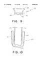
- FIG. 9is a bottom view of an alternative embodiment of the fiber optic cable bend radius control device in accordance with the invention.
- FIG. 10is a front view of an alternative embodiment of the fiber optic cable bend radius control device in accordance with the invention.
- Channel member 2has a base 4 and two side walls 6 and 8.
- the base 4 and side walls 6 and 8are arranged so that the channel member 2 is U-shaped in cross-section.
- Side walls 6 and 8each have two ends. One end of side wall 6 and one end of side wall 8 are attached to base 4. The opposite ends of side walls 6 and 8 are free.
- Side walls 6 and 8have slots 10.
- the slots 10extend from the free end of side walls 6 and 8 toward the ends of side walls 6 and 8 that are attached to base 4.
- Slots 10have wide portions 14 and narrow portions 16. The wide portions of slots 10 are approximately centered on the side walls 6 and 8 between the ends of the side walls attached to the base 4 and the free ends. Wide portions 14 of slots 10 have edges 14a, 14b, 14c and 14d. The narrow portions 16 of slots 10 extend from the free ends of side walls 6 and 8 to the edges 14d of wide portions 14 of slots 10.
- Side walls 6 and 8have retainers 12 at the free ends of the side walls.
- Retainers 12are designed to secure a cover (not shown) to channel member 2.
- the narrow portions 16 of slots 10are located in between retainers 12 on the free ends of side walls 6 and 8.
- FIGS. 1-3there is shown an embodiment of a fiber optic cable bend radius control device 20 in accordance with the invention.
- FIG. 2shows a vertical cross-sectional of the fiber optic cable bend radius control device 20 in the environment of its intended use.
- FIG. 3is side view of the fiber optic cable bend radius control device 20.
- the fiber optic cable bend radius control device 20attaches to the wide portion 14 of slot 10 of channel member 2.
- each part 20a and 20b of the fiber optic cable bend radius control device 20is comprised of a continuous sheet of material formed to have a gradually curved surface 22, horizontal portions 24 and 26 and closely spaced vertical portions 28 and 30.
- the fiber optic cable bend radius control device 20is snapped onto opposite edges 14a and 14c of wide portion 14 of slot 10 in channel member 2.
- Vertical portions 28 and 30frictionally engage and thereby secure the fiber optic cable bend radius control device 20 to the opposite edges 14a and 14c of wide portion 14 of slot 10 as shown in FIGS. 1 and 2.
- Fiber optic cable bend radius control device 20is secured to the opposite edges 14a and 14c of wide portion 14 of slot 10, fiber optic cable 32 in channel member 2 is placed in the narrow portion 16 of slot 10 and is pushed toward the wide portion 14 of slot 10 until the fiber optic cable 32 is in the wide portion 14 of slot 10. Once the fiber optic cable 32 is in the wide portion 14 of slot 10, the fiber optic cable can rest on the curved surface 22 of the fiber optic cable bend radius control device 20. Curved surface 22 provides a smooth and continuous surface to guide, protect and control the bend radius of fiber optic cables 32 extending from channel member 2 through slots 10 into enclosure 34.
- FIGS. 4-10there is shown another embodiment of a fiber optic cable bend radius control device 20' in accordance with the invention.
- FIG. 4is a perspective view of the fiber optical cable bend radius control device 20' in the environment of its intended use.
- FIG. 5is a side view of the fiber optic cable bend radius control device 20' in the environment of its intended use.
- FIG. 6is a perspective view of the fiber optic cable bend radius control device 20'.
- FIG. 7is a side view of the fiber optic cable bend radius control device 20'.
- FIG. 8is a top view of the fiber optic cable bend radius control device 20'.
- FIG. 9is a bottom view of the fiber optic cable bend radius control device 20'.
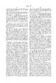
- FIG. 10is a front view of the fiber optic cable bend radius control device 20' shown in a deflected position.
- the fiber optic cable bend radius control device 20'attaches to the wide portion 14 of slot 10 of channel member 2.
- the embodiment of the fiber optic cable bend radius control device 20' shown in FIGS. 4-10specifically attaches to the edges 14a, 14b and 14c of wide portion 14 of slot 10 in side wall 6 of channel member 2.
- the fiber optic cable bend radius control device 20'is a U-shaped one piece trumpet design.
- the fiber optic cable bend radius control device 20'has projections 42, 44, 46 and 48 that cooperate to secure the device 20' in the wide portion 14 of slot 10.
- the fiber optic cable bend radius control device 20'is snapped into the wide portion 14 of slots 10 in channel member 2.
- Projections 42, 46 and 48deflect as the fiber optic cable bend radius control device 20' is forced into the slot 10 and rebound when the device 20' is properly positioned in the wide portion 14 of the slot 10.
- Projection 44serves as a backstop for the fiber optic cable bend radius control device 20' once fully inserted. In that manner, projections 42, 44, 46 and 48 secure the fiber optic cable bend radius control device 20' to the edges 14a, 14b and 14c of wide portion 14 of slot 10 of side wall 6 of channel member 2 as shown in FIGS. 4 and 5.
- the fiber optic cable bend radius control device 20'has a base 50 and two sides 52 and 54 generally comprising the U-shaped device 20' and a portion 38 extending away from projections 42, 44, 46 and 48. As shown in FIG. 10, the sides 52 and 54 may be deflected, temporarily deforming the fiber optic cable bend radius control device 20' from its U-shaped cross-section to facilitate the attachment of the device 20' to edges 14a, 14b and 14c of wide portion 14 of slot 10.
- the flexure, shown at 56 in FIG. 10is preferably up to two degrees with respect to each side 52 and 54 of the fiber optic cable bend radius control device 20'.
- the portion 38 of the fiber optic cable bend radius control device 20' extending away from projections 42, 44, 46 and 48flares outwardly in a continuous gradually curved surface 40.
- Fiber optic cable bend radius control device 20'is secured to the edges 14a, 14b and 14c of wide portion 14 of slot 10
- fiber optic cable in slotted channel member 2is placed in the narrow portion 16 of slot 10 and is pushed toward the wide portion 14 of slot 10 until the fiber optic cable is in the wide portion 14 of slot 10.
- the fiber optic cablecan rest on the curved surface 40 of the fiber optic cable bend radius control device 20'. Curved surface 40 provides a smooth and continuous surface to guide, protect and control the bend radius of fiber optic cables extending from channel member 2 through slots 10 into an enclosure.
- the fiber optic cable bend radius control device in accordance with the inventionmust provide adequate support to and prevent uncontrolled bending or tension of the fiber optic cables. Constructing the fiber optic cable bend radius control device of suitable materials would be apparent to persons skilled in the art.
- the fiber optic cable bend radius control device in accordance with the inventionis preferably formed of a flame resistant high impact thermoplastic material. Such a material is rigid but provides for some flexure during insertion of the fiber optic cable bend radius control device into the wide portion of the slot. With respect to the embodiment of the fiber optic cable bend radius control device 20' shown in FIGS.
- flexure of the device 20'enable s frictional engagement of the vertical projections 28 and 30 with the opposite edges 14a and 14b of the wide portion 14 of the slot 10.
- flexure of th e device 20'enables deflection and rebound of the projections 42, 46 and 48 and deflection of sides 52 and 54 to enable securing of the device 20' to the edges 14a, 14b and 14c of the wide portion 14 of the slot 10.
- Other materials for construction of the fiber optic cable bend radius control device adequate to guide, protect, support and provide bend radius controlwould be apparent to persons skilled in the art.
- the fiber optic cable bend radius control device in accordance with the inventionis made of suitable dimensions to fulfill its intended purpose.
- the embodiment of the fiber optic cable bend radius control device 20' shown in FIGS. 4-10may be constructed having a height of 2.79 inches, a width of 1.83 inches and a depth of 0.98 inches.
- Other dimensions for the fiber optic cable bend radius control device adequate to guide, protect, support and provide bend radius control for fiber optic cableswould be apparent to persons skilled in the art.
Landscapes
- Physics & Mathematics (AREA)
- General Physics & Mathematics (AREA)
- Optics & Photonics (AREA)
- Light Guides In General And Applications Therefor (AREA)
- Details Of Indoor Wiring (AREA)
Abstract
Description
Claims (6)
Priority Applications (1)
| Application Number | Priority Date | Filing Date | Title |
|---|---|---|---|
| US09/261,610US6044194A (en) | 1997-03-17 | 1999-02-26 | Fiber optic cable bend radius control |
Applications Claiming Priority (2)
| Application Number | Priority Date | Filing Date | Title |
|---|---|---|---|
| US81940797A | 1997-03-17 | 1997-03-17 | |
| US09/261,610US6044194A (en) | 1997-03-17 | 1999-02-26 | Fiber optic cable bend radius control |
Related Parent Applications (1)
| Application Number | Title | Priority Date | Filing Date |
|---|---|---|---|
| US81940797AContinuation | 1997-03-17 | 1997-03-17 |
Related Child Applications (1)
| Application Number | Title | Priority Date | Filing Date |
|---|---|---|---|
| US29/102,396ContinuationUSD431447S (en) | 1999-03-24 | 1999-03-24 | Cable bend radius control attachment |
Publications (1)
| Publication Number | Publication Date |
|---|---|
| US6044194Atrue US6044194A (en) | 2000-03-28 |
Family
ID=25228065
Family Applications (1)
| Application Number | Title | Priority Date | Filing Date |
|---|---|---|---|
| US09/261,610Expired - LifetimeUS6044194A (en) | 1997-03-17 | 1999-02-26 | Fiber optic cable bend radius control |
Country Status (2)
| Country | Link |
|---|---|
| US (1) | US6044194A (en) |
| WO (1) | WO1998041891A1 (en) |
Cited By (92)
| Publication number | Priority date | Publication date | Assignee | Title |
|---|---|---|---|---|
| USD448737S1 (en) | 2000-06-23 | 2001-10-02 | Shinagawa Shoko Co., Ltd. | Supporting and protecting duct for wiring distribution |
| US6321017B1 (en)* | 1999-09-21 | 2001-11-20 | Lucent Technologies Inc. | Portal bend limiter/strain reliever for fiber optic closure exit portal |
| DE10051660A1 (en)* | 2000-10-18 | 2002-05-02 | Rxs Kabelgarnituren Gmbh & Co | Fastening structure for use with a bundle of optical waveguide wires, has a long stretched-out clamp strap with a concave section to hold the bundle and a base to fasten the strap to with a bundle of wires in between. |
| US6411766B1 (en)* | 1999-10-07 | 2002-06-25 | Ronald D. Bechamps | Devices for protecting and routing optical fibers in a rack |
| USD459976S1 (en) | 2001-07-13 | 2002-07-09 | Senior Industries, Inc. | Distributing end ring |
| USD463253S1 (en) | 2002-03-27 | 2002-09-24 | Panduit Corp. | Vertical cable manager |
| US20020136520A1 (en)* | 2001-03-21 | 2002-09-26 | Janus Neal A. | Optical fiber cable swivel for fiber optic distribution frames |
| US6476327B1 (en)* | 2000-06-01 | 2002-11-05 | Panduit Corp. | Split fiber cover and raceway fitting |
| US6512875B1 (en)* | 2000-10-06 | 2003-01-28 | Adc Telecommunications, Inc. | Optical cable troughs, fittings, and couplings |
| US6539161B2 (en)* | 2001-03-16 | 2003-03-25 | Adc Telecommunications, Inc. | Cable routing clip |
| US6553172B2 (en) | 2001-06-08 | 2003-04-22 | Ceyba Inc. | Fiber optic cable routing device with pre-alignment feature |
| US6586680B1 (en) | 2000-06-02 | 2003-07-01 | Panduit Corp. | Modular bend radius control fixture |
| US6614665B2 (en)* | 2001-04-16 | 2003-09-02 | Adc Telecommunications, Inc. | Cable management bracket for a telecommunications rack |
| US6671447B1 (en)* | 2001-11-02 | 2003-12-30 | Ciena Corporation | Optical fiber organizer for organizing optical fiber inside of a fiber duct |
| US20040001685A1 (en)* | 2002-06-27 | 2004-01-01 | Daoud Bassel H. | Optical fiber closure having an integrated bend limiting feature |
| US20040136676A1 (en)* | 2003-01-15 | 2004-07-15 | Adc Telecommunications, Inc. | Rotating radius limiter for cable management panel and methods |
| US6768858B2 (en)* | 2001-03-16 | 2004-07-27 | Adc Telecommunications, Inc. | Cable clip with segregator and method |
| US6785459B2 (en)* | 2001-06-26 | 2004-08-31 | Adc Telecommunications, Inc. | Cable management brackets and cabinet |
| US6937807B2 (en) | 2002-04-24 | 2005-08-30 | Adc Telecommunications, Inc. | Cable management panel with sliding drawer |
| US20060127027A1 (en)* | 2001-07-06 | 2006-06-15 | Adc Telecommunications, Inc. | Cable management panel with sliding drawer and methods |
| EP1362250A4 (en)* | 2001-01-25 | 2007-03-14 | Hector D Petri | Fiber optic cable guide |
| US20070230892A1 (en)* | 2000-10-06 | 2007-10-04 | Adc Telecommunications, Inc. | Cable exit trough with cover |
| US20070230888A1 (en)* | 2000-10-06 | 2007-10-04 | Adc Telecommunications, Inc. | Cable exit trough with insert |
| US20070253672A1 (en)* | 1997-11-17 | 2007-11-01 | Adc Telecommunications, Inc. | Optical cable exit trough |
| US20080123301A1 (en)* | 2006-11-29 | 2008-05-29 | Panduit Corp. | Bend radius post |
| US20090050349A1 (en)* | 2007-08-20 | 2009-02-26 | Panduit Corp. | Compact Spillover Fitting and Method of Use Thereof |
| US20090236117A1 (en)* | 2008-01-07 | 2009-09-24 | Chatsworth Products, Inc. | Cable management accessories |
| US20100126950A1 (en)* | 2008-11-26 | 2010-05-27 | Richard Gregg Winn | Cable tray |
| US20100126951A1 (en)* | 2008-11-26 | 2010-05-27 | Richard Gregg Winn | Wire cable tray |
| US20100142176A1 (en)* | 2008-12-04 | 2010-06-10 | Panduit Corp. | Spillover Fitting |
| US20100195968A1 (en)* | 2000-01-24 | 2010-08-05 | Adc Telecommunications, Inc. | Cable management panel with sliding drawer |
| US20100200707A1 (en)* | 2008-01-07 | 2010-08-12 | Chatsworth Products, Inc. | Cable management accessories |
| US20100266256A1 (en)* | 2009-04-20 | 2010-10-21 | Adc Telecommunications, Inc. | Fiber Retainer for Cable Trough Member |
| US20100278502A1 (en)* | 2009-04-30 | 2010-11-04 | Verizon Patent And Licensing Inc. | Raceway with media retaining offset slots |
| USD629289S1 (en)* | 2010-06-29 | 2010-12-21 | Chatsworth Products, Inc. | Cable guide projection with boss |
| US20110011612A1 (en)* | 2009-07-15 | 2011-01-20 | Derek Sayres | Twist-in latching arrangement for cable management structure |
| USD635935S1 (en) | 2010-01-16 | 2011-04-12 | Chatsworth Products, Inc. | Cover for cable management raceway |
| USD637066S1 (en)* | 2010-06-29 | 2011-05-03 | Chatsworth Products, Inc. | Cable guide projection |
| USD637065S1 (en)* | 2010-01-16 | 2011-05-03 | Chatsworth Products, Inc. | Cable guide projection |
| USD640528S1 (en) | 2010-06-29 | 2011-06-28 | Chatsworth Products, Inc. | Cable guide projection with boss |
| US20110214776A1 (en)* | 2008-11-26 | 2011-09-08 | Richard Gregg Winn | Cable tray |
| WO2011140543A1 (en)* | 2010-05-07 | 2011-11-10 | Corning Cable Systems Llc | Fiber optic housings configured for tool-less assembly, and related components and methods |
| USD651570S1 (en) | 2010-01-16 | 2012-01-03 | Chatsworth Products, Inc. | Raceway for cable management |
| USD653623S1 (en) | 2010-01-16 | 2012-02-07 | Chatsworth Products, Inc. | Raceway for cable management |
| US8424814B2 (en) | 2010-05-19 | 2013-04-23 | Panduit Corp. | Cable tray cable routing system |
| US8457464B2 (en) | 2011-09-26 | 2013-06-04 | Hubbell Incorporated | Cable enclosure and radius-limiting cable guide with integral magnetic door catch |
| WO2014118223A1 (en)* | 2013-01-29 | 2014-08-07 | Tyco Electronics Raychem Bvba | Cable storage device |
| US8901418B2 (en) | 2012-06-25 | 2014-12-02 | Panduit Corp. | Server cabinet |
| US9002166B2 (en) | 2011-10-07 | 2015-04-07 | Adc Telecommunications, Inc. | Slidable fiber optic connection module with cable slack management |
| US9057859B2 (en) | 2011-10-07 | 2015-06-16 | Adc Telecommunications, Inc. | Slidable fiber optic connection module with cable slack management |
| US9075203B2 (en) | 2012-01-17 | 2015-07-07 | Adc Telecommunications, Inc. | Fiber optic adapter block |
| US9128262B2 (en) | 2013-02-05 | 2015-09-08 | Adc Telecommunications, Inc. | Slidable telecommunications tray with cable slack management |
| US9144175B2 (en) | 2012-06-25 | 2015-09-22 | Panduit Corp. | Electronics cabinet |
| US9170391B2 (en) | 2011-10-07 | 2015-10-27 | Adc Telecommunications, Inc. | Slidable fiber optic connection module with cable slack management |
| US9195021B2 (en) | 2012-09-21 | 2015-11-24 | Adc Telecommunications, Inc. | Slidable fiber optic connection module with cable slack management |
| US9389384B2 (en) | 2013-02-27 | 2016-07-12 | Commscope Technologies Llc | Slidable fiber optic connection module with cable slack management |
| US9519118B2 (en) | 2010-04-30 | 2016-12-13 | Corning Optical Communications LLC | Removable fiber management sections for fiber optic housings, and related components and methods |
| US9541726B2 (en) | 2013-04-24 | 2017-01-10 | Adc Czech Republic, S.R.O. | Optical fiber distribution system |
| US9568699B2 (en) | 2013-01-29 | 2017-02-14 | CommScope Connectivity Belgium BVBA | Optical fiber distribution system |
| JP2018031875A (en)* | 2016-08-24 | 2018-03-01 | 富士通株式会社 | Cable housing mechanism and electronic device |
| US9910236B2 (en) | 2008-08-29 | 2018-03-06 | Corning Optical Communications LLC | High density and bandwidth fiber optic apparatuses and related equipment and methods |
| US9943003B2 (en) | 2012-06-25 | 2018-04-10 | Panduit Corp. | Electronics cabinet |
| US10003180B1 (en) | 2015-11-30 | 2018-06-19 | Chatsworth Products, Inc. | Cable pathway divider and method for installing same |
| US10082636B2 (en) | 2012-09-21 | 2018-09-25 | Commscope Technologies Llc | Slidable fiber optic connection module with cable slack management |
| US10094996B2 (en) | 2008-08-29 | 2018-10-09 | Corning Optical Communications, Llc | Independently translatable modules and fiber optic equipment trays in fiber optic equipment |
| US10247886B2 (en) | 2014-12-10 | 2019-04-02 | Commscope Technologies Llc | Fiber optic cable slack management module |
| US10261281B2 (en) | 2015-04-03 | 2019-04-16 | CommScope Connectivity Belgium BVBA | Telecommunications distribution elements |
| US10409020B2 (en) | 2013-04-24 | 2019-09-10 | CommScope Connectivity Belgium BVBA | Universal mounting mechanism for mounting a telecommunications chassis to a telecommunciations fixture |
| US10495237B1 (en) | 2017-03-29 | 2019-12-03 | Robroy Industries—Texas, LLC | Piping and conduit support rack |
| US10539757B2 (en) | 2016-04-19 | 2020-01-21 | Commscope, Inc. Of North Carolina | Telecommunications chassis with slidable trays |
| EP3731360A4 (en)* | 2017-12-19 | 2021-08-04 | Sumitomo Electric Industries, Ltd. | CABLE CLAMP |
| US11215767B2 (en) | 2017-06-07 | 2022-01-04 | Commscope Technologies Llc | Fiber optic adapter and cassette |
| US11256054B2 (en) | 2018-04-16 | 2022-02-22 | Commscope Technologies Llc | Adapter structure |
| US11294136B2 (en) | 2008-08-29 | 2022-04-05 | Corning Optical Communications LLC | High density and bandwidth fiber optic apparatuses and related equipment and methods |
| US11385429B2 (en) | 2017-10-18 | 2022-07-12 | Commscope Technologies Llc | Fiber optic connection cassette |
| US11409067B2 (en) | 2018-08-31 | 2022-08-09 | CommScope Connectivity Belgium BVBA | Frame assemblies for optical fiber distribution elements |
| US11448844B2 (en) | 2018-08-31 | 2022-09-20 | CommScope Connectivity Belgium BVBA | Frame assemblies for optical fiber distribution elements |
| US11448831B2 (en) | 2018-08-31 | 2022-09-20 | CommScope Connectivity Belgium BVBA | Frame assemblies for optical fiber distribution elements |
| US11448845B2 (en) | 2018-08-31 | 2022-09-20 | CommScope Connectivity Belgium BVBA | Frame assemblies for optical fiber distribution elements |
| WO2022267240A1 (en)* | 2021-06-24 | 2022-12-29 | 烽火通信科技股份有限公司 | Clamping slot for wiring in building, and method for using same |
| US11635578B2 (en) | 2018-04-17 | 2023-04-25 | CommScope Connectivity Belgium BVBA | Telecommunications distribution elements |
| US11638946B2 (en) | 2020-11-23 | 2023-05-02 | International Business Machines Corporation | Cable bend radius gauge |
| US11674345B2 (en) | 2016-04-19 | 2023-06-13 | Commscope, Inc. Of North Carolina | Door assembly for a telecommunications chassis with a combination hinge structure |
| WO2023129488A1 (en) | 2021-12-31 | 2023-07-06 | Commscope Technologies Llc | Data and high voltage power network with consolidated enclosure |
| EP4273604A1 (en) | 2022-05-06 | 2023-11-08 | Sterlite Technologies Limited | Fiber bend control fixture |
| US11852882B2 (en) | 2018-02-28 | 2023-12-26 | Commscope Technologies Llc | Packaging assembly for telecommunications equipment |
| US11947177B2 (en) | 2019-01-25 | 2024-04-02 | CommScope Connectivity Belgium BVBA | Frame assemblies for optical fiber distribution elements |
| US12007615B2 (en) | 2018-10-23 | 2024-06-11 | CommScope Connectivity Belgium BVBA | Frame assemblies for optical fiber distribution elements |
| US12050358B2 (en) | 2018-08-31 | 2024-07-30 | CommScope Connectivity Belgium BVBA | Frame assemblies for optical fiber distribution elements |
| NO348159B1 (en)* | 2020-09-14 | 2024-09-09 | Nexans | Bend guide structure |
| US12099246B2 (en) | 2020-01-24 | 2024-09-24 | CommScope Connectivity Belgium BVBA | Telecommunications distribution elements |
| US12174443B2 (en) | 2020-01-22 | 2024-12-24 | CommScope Connectivity Belgium BVBA | Cable termination units for optical fiber distribution elements |
Families Citing this family (4)
| Publication number | Priority date | Publication date | Assignee | Title |
|---|---|---|---|---|
| DE10005294A1 (en)* | 2000-02-07 | 2001-08-09 | Siemens Ag | Cable guide for connecting distribution boxes with glass fiber patch cables has patch cable leadthrough devices on distribution box housing walls, cable channel between housings |
| US6712115B2 (en) | 2000-04-14 | 2004-03-30 | Ren Judkins | Headrail for double shade |
| WO2001080389A2 (en)* | 2000-04-17 | 2001-10-25 | Ciena Corporation | Fiber optic cable duct fan-out with bend protection |
| DE102015006829B3 (en)* | 2015-06-02 | 2016-08-25 | Langmatz Gmbh | Fiber distribution frame |
Citations (21)
| Publication number | Priority date | Publication date | Assignee | Title |
|---|---|---|---|---|
| US2258745A (en)* | 1939-04-22 | 1941-10-14 | American Brake Shoe & Foundry | Duct leader |
| CH403904A (en)* | 1961-04-29 | 1965-12-15 | Theysohn Albert | Cable duct |
| US4157799A (en)* | 1976-11-23 | 1979-06-12 | Hans Simon | Cable grommet with traction relief |
| US4717231A (en)* | 1983-01-05 | 1988-01-05 | Vincent Dewez | Interconnecting and distributing box for optical fibers |
| US4835921A (en)* | 1988-07-01 | 1989-06-06 | Molex Incorporated | Raceway frame and method for curved modular wall panel |
| DE3742448A1 (en)* | 1987-12-15 | 1989-06-29 | Philips Patentverwaltung | Cable duct |
| US5065556A (en)* | 1990-05-15 | 1991-11-19 | Westinghouse Electric Corp. | Space dividing partition system having an electrical raceway |
| US5067784A (en)* | 1990-11-19 | 1991-11-26 | George Debortoli | Connector holders |
| US5079389A (en)* | 1990-11-05 | 1992-01-07 | Nelson Carl A | Wire guard coupling |
| US5100221A (en)* | 1990-01-22 | 1992-03-31 | Porta Systems Corp. | Optical fiber cable distribution frame and support |
| US5119459A (en)* | 1991-02-15 | 1992-06-02 | Porta Systems Corp. | Optical fiber storage and distribution cabinet |
| US5241617A (en)* | 1989-04-13 | 1993-08-31 | British Telecommunications Public Limited Company | Optical fibre back plane |
| US5280138A (en)* | 1992-03-31 | 1994-01-18 | Virginia Plastics Company, Inc. | Cable protector |
| US5287428A (en)* | 1991-10-16 | 1994-02-15 | Fujitsu Limited | Optical fiber cable distribution apparatus |
| US5335349A (en)* | 1992-12-14 | 1994-08-02 | Telect, Inc. | Telecommunication overhead cable distribution assembly |
| US5339379A (en)* | 1993-06-18 | 1994-08-16 | Telect, Inc. | Telecommunication fiber optic cable distribution apparatus |
| US5353367A (en)* | 1993-11-29 | 1994-10-04 | Northern Telecom Limited | Distribution frame and optical connector holder combination |
| US5394502A (en)* | 1993-12-21 | 1995-02-28 | United Technologies Corporation | Fiber optic cable harness break-out fitting |
| US5469893A (en)* | 1993-12-21 | 1995-11-28 | Panduit Corp. | Tab and slot fiber optic fitting |
| US5488198A (en)* | 1994-09-01 | 1996-01-30 | Kramer; Hy | Protection device for apertures in metal studs or panels |
| US5640482A (en)* | 1995-08-31 | 1997-06-17 | The Whitaker Corporation | Fiber optic cable management rack |
- 1998
- 1998-02-18WOPCT/US1998/003159patent/WO1998041891A1/enactiveApplication Filing
- 1999
- 1999-02-26USUS09/261,610patent/US6044194A/ennot_activeExpired - Lifetime
Patent Citations (21)
| Publication number | Priority date | Publication date | Assignee | Title |
|---|---|---|---|---|
| US2258745A (en)* | 1939-04-22 | 1941-10-14 | American Brake Shoe & Foundry | Duct leader |
| CH403904A (en)* | 1961-04-29 | 1965-12-15 | Theysohn Albert | Cable duct |
| US4157799A (en)* | 1976-11-23 | 1979-06-12 | Hans Simon | Cable grommet with traction relief |
| US4717231A (en)* | 1983-01-05 | 1988-01-05 | Vincent Dewez | Interconnecting and distributing box for optical fibers |
| DE3742448A1 (en)* | 1987-12-15 | 1989-06-29 | Philips Patentverwaltung | Cable duct |
| US4835921A (en)* | 1988-07-01 | 1989-06-06 | Molex Incorporated | Raceway frame and method for curved modular wall panel |
| US5241617A (en)* | 1989-04-13 | 1993-08-31 | British Telecommunications Public Limited Company | Optical fibre back plane |
| US5100221A (en)* | 1990-01-22 | 1992-03-31 | Porta Systems Corp. | Optical fiber cable distribution frame and support |
| US5065556A (en)* | 1990-05-15 | 1991-11-19 | Westinghouse Electric Corp. | Space dividing partition system having an electrical raceway |
| US5079389A (en)* | 1990-11-05 | 1992-01-07 | Nelson Carl A | Wire guard coupling |
| US5067784A (en)* | 1990-11-19 | 1991-11-26 | George Debortoli | Connector holders |
| US5119459A (en)* | 1991-02-15 | 1992-06-02 | Porta Systems Corp. | Optical fiber storage and distribution cabinet |
| US5287428A (en)* | 1991-10-16 | 1994-02-15 | Fujitsu Limited | Optical fiber cable distribution apparatus |
| US5280138A (en)* | 1992-03-31 | 1994-01-18 | Virginia Plastics Company, Inc. | Cable protector |
| US5335349A (en)* | 1992-12-14 | 1994-08-02 | Telect, Inc. | Telecommunication overhead cable distribution assembly |
| US5339379A (en)* | 1993-06-18 | 1994-08-16 | Telect, Inc. | Telecommunication fiber optic cable distribution apparatus |
| US5353367A (en)* | 1993-11-29 | 1994-10-04 | Northern Telecom Limited | Distribution frame and optical connector holder combination |
| US5394502A (en)* | 1993-12-21 | 1995-02-28 | United Technologies Corporation | Fiber optic cable harness break-out fitting |
| US5469893A (en)* | 1993-12-21 | 1995-11-28 | Panduit Corp. | Tab and slot fiber optic fitting |
| US5488198A (en)* | 1994-09-01 | 1996-01-30 | Kramer; Hy | Protection device for apertures in metal studs or panels |
| US5640482A (en)* | 1995-08-31 | 1997-06-17 | The Whitaker Corporation | Fiber optic cable management rack |
Cited By (248)
| Publication number | Priority date | Publication date | Assignee | Title |
|---|---|---|---|---|
| US8768135B2 (en) | 1997-11-17 | 2014-07-01 | Adc Telecommunications, Inc. | Optical cable exit trough |
| US20110229103A1 (en)* | 1997-11-17 | 2011-09-22 | Adc Telecommunications, Inc. | Optical cable exit trough |
| US8582944B2 (en) | 1997-11-17 | 2013-11-12 | Adc Telecommunications, Inc. | Optical cable exit trough |
| US8965169B2 (en)* | 1997-11-17 | 2015-02-24 | Adc Telecommunications, Inc. | Optical cable exit trough |
| US20070253672A1 (en)* | 1997-11-17 | 2007-11-01 | Adc Telecommunications, Inc. | Optical cable exit trough |
| US9453981B2 (en) | 1997-11-17 | 2016-09-27 | Commscope Technologies Llc | Optical cable exit trough |
| US8886004B2 (en)* | 1997-11-17 | 2014-11-11 | Adc Telecommunications, Inc. | Optical cable exit trough |
| US20080199141A1 (en)* | 1997-11-17 | 2008-08-21 | Adc Telecommunications, Inc. | Optical cable exit trough |
| US6321017B1 (en)* | 1999-09-21 | 2001-11-20 | Lucent Technologies Inc. | Portal bend limiter/strain reliever for fiber optic closure exit portal |
| US6411766B1 (en)* | 1999-10-07 | 2002-06-25 | Ronald D. Bechamps | Devices for protecting and routing optical fibers in a rack |
| US9664870B2 (en) | 2000-01-24 | 2017-05-30 | Commscope Technologies Llc | Cable management panel with sliding drawer |
| US8655136B2 (en) | 2000-01-24 | 2014-02-18 | Adc Telecommunications, Inc. | Cable management panel with sliding drawer |
| US8078030B2 (en)* | 2000-01-24 | 2011-12-13 | Adc Telecommunications, Inc. | Cable management panel with sliding drawer |
| US20100195968A1 (en)* | 2000-01-24 | 2010-08-05 | Adc Telecommunications, Inc. | Cable management panel with sliding drawer |
| US10459182B2 (en) | 2000-01-24 | 2019-10-29 | Commscope Technologies Llc | Cable management panel with sliding drawer |
| US6476327B1 (en)* | 2000-06-01 | 2002-11-05 | Panduit Corp. | Split fiber cover and raceway fitting |
| US6586680B1 (en) | 2000-06-02 | 2003-07-01 | Panduit Corp. | Modular bend radius control fixture |
| USD448737S1 (en) | 2000-06-23 | 2001-10-02 | Shinagawa Shoko Co., Ltd. | Supporting and protecting duct for wiring distribution |
| US7551827B2 (en) | 2000-10-06 | 2009-06-23 | Adc Telecommunications, Inc. | Cable exit trough with insert |
| US8306381B2 (en) | 2000-10-06 | 2012-11-06 | Adc Telecommunications, Inc. | Cable exit trough with insert |
| US8041174B2 (en) | 2000-10-06 | 2011-10-18 | Adc Telecommunications, Inc. | Cable exit trough with insert |
| US8041176B2 (en) | 2000-10-06 | 2011-10-18 | Adc Telecommunications, Inc. | Cable exit trough with cover |
| US20110116754A1 (en)* | 2000-10-06 | 2011-05-19 | Adc Telecommunicatios, Inc. | Cable exit trough with insert |
| US9470866B2 (en) | 2000-10-06 | 2016-10-18 | Commscope Technologies Llc | Cable exit trough with insert |
| US7715684B2 (en) | 2000-10-06 | 2010-05-11 | Adc Telecommunications, Inc. | Cable exit trough with cover |
| US7885503B2 (en) | 2000-10-06 | 2011-02-08 | Adc Telecommunications, Inc. | Cable exit trough with insert |
| US20100002998A1 (en)* | 2000-10-06 | 2010-01-07 | Adc Telecommunications, Inc. | Cable exit trough with insert |
| US20070230892A1 (en)* | 2000-10-06 | 2007-10-04 | Adc Telecommunications, Inc. | Cable exit trough with cover |
| US8335422B2 (en) | 2000-10-06 | 2012-12-18 | Adc Telecommunications, Inc. | Cable exit trough with insert |
| US8712205B2 (en) | 2000-10-06 | 2014-04-29 | Adc Telecommunications, Inc. | Cable exit trough with insert |
| US20100266255A1 (en)* | 2000-10-06 | 2010-10-21 | Adc Telecommunications, Inc. | Cable exit trough with cover |
| US6512875B1 (en)* | 2000-10-06 | 2003-01-28 | Adc Telecommunications, Inc. | Optical cable troughs, fittings, and couplings |
| US20070230888A1 (en)* | 2000-10-06 | 2007-10-04 | Adc Telecommunications, Inc. | Cable exit trough with insert |
| DE10051660A1 (en)* | 2000-10-18 | 2002-05-02 | Rxs Kabelgarnituren Gmbh & Co | Fastening structure for use with a bundle of optical waveguide wires, has a long stretched-out clamp strap with a concave section to hold the bundle and a base to fasten the strap to with a bundle of wires in between. |
| DE10051660B4 (en)* | 2000-10-18 | 2006-05-11 | CCS Technology, Inc., Wilmington | Fastening arrangement of an optical fiber bundle |
| EP1362250A4 (en)* | 2001-01-25 | 2007-03-14 | Hector D Petri | Fiber optic cable guide |
| US6665484B2 (en) | 2001-03-16 | 2003-12-16 | Adc Telecommunications, Inc. | Cable clip |
| US6771871B2 (en) | 2001-03-16 | 2004-08-03 | Adc Telecommunications, Inc. | Cable clip |
| US7097473B2 (en) | 2001-03-16 | 2006-08-29 | Adc Telecommunications, Inc. | Cable clip |
| US7346252B2 (en) | 2001-03-16 | 2008-03-18 | Adc Telecommunications, Inc. | Cable clip and cable riser integrating a cable clip |
| US20060008235A1 (en)* | 2001-03-16 | 2006-01-12 | Adc Telecommunications, Inc. | Cable clip |
| US6947654B2 (en)* | 2001-03-16 | 2005-09-20 | Adc Telecommunications, Inc. | Cable clip with movable gate |
| US6892020B2 (en) | 2001-03-16 | 2005-05-10 | Adc Telecommunications, Inc. | Cable routing clip with movable gate |
| US6539161B2 (en)* | 2001-03-16 | 2003-03-25 | Adc Telecommunications, Inc. | Cable routing clip |
| US20040151465A1 (en)* | 2001-03-16 | 2004-08-05 | Adc Telecommunication, Inc. | Cable clip |
| US20040149486A1 (en)* | 2001-03-16 | 2004-08-05 | Adc Telecommunications, Inc. | Cable clip |
| US20070177847A1 (en)* | 2001-03-16 | 2007-08-02 | Adc Telecommunications, Inc. | Cable clip |
| US6768858B2 (en)* | 2001-03-16 | 2004-07-27 | Adc Telecommunications, Inc. | Cable clip with segregator and method |
| US20020136520A1 (en)* | 2001-03-21 | 2002-09-26 | Janus Neal A. | Optical fiber cable swivel for fiber optic distribution frames |
| US6614665B2 (en)* | 2001-04-16 | 2003-09-02 | Adc Telecommunications, Inc. | Cable management bracket for a telecommunications rack |
| US6553172B2 (en) | 2001-06-08 | 2003-04-22 | Ceyba Inc. | Fiber optic cable routing device with pre-alignment feature |
| US6785459B2 (en)* | 2001-06-26 | 2004-08-31 | Adc Telecommunications, Inc. | Cable management brackets and cabinet |
| US7373071B2 (en) | 2001-07-06 | 2008-05-13 | Adc Telecommunications, Inc. | Cable management panel with sliding drawer and methods |
| US7664362B2 (en) | 2001-07-06 | 2010-02-16 | Adc Telecommunications, Inc. | Cable management panel with sliding drawer and methods |
| US20070201806A1 (en)* | 2001-07-06 | 2007-08-30 | Adc Telecommunications, Inc. | Cable management panel with sliding drawer and methods |
| US7480438B2 (en) | 2001-07-06 | 2009-01-20 | Adc Telecommunications, Inc. | Cable management panel with sliding drawer and methods |
| US10146023B2 (en) | 2001-07-06 | 2018-12-04 | Commscope Technologies Llc | Cable management panel with sliding drawer and methods |
| US7231125B2 (en) | 2001-07-06 | 2007-06-12 | Adc Telecommunications, Inc. | Cable management panel with sliding drawer and methods |
| US10989889B2 (en) | 2001-07-06 | 2021-04-27 | Commscope Technologies Llc | Cable management panel with sliding drawer and methods |
| US7079744B2 (en)* | 2001-07-06 | 2006-07-18 | Adc Telecommunications, Inc. | Cable management panel with sliding drawer and methods |
| US20060127027A1 (en)* | 2001-07-06 | 2006-06-15 | Adc Telecommunications, Inc. | Cable management panel with sliding drawer and methods |
| US9442267B2 (en) | 2001-07-06 | 2016-09-13 | Commscope Technologies Llc | Cable management panel with sliding drawer and methods |
| US8078029B2 (en) | 2001-07-06 | 2011-12-13 | Adc Telecommunications, Inc. | Cable management panel with sliding drawer and methods |
| US20080267573A1 (en)* | 2001-07-06 | 2008-10-30 | Adc Telecommunications, Inc. | Cable Management panel with sliding drawer and methods |
| US11320619B2 (en) | 2001-07-06 | 2022-05-03 | Commscope Technologies Llc | Cable management panel with sliding drawer and methods |
| USD459976S1 (en) | 2001-07-13 | 2002-07-09 | Senior Industries, Inc. | Distributing end ring |
| US6671447B1 (en)* | 2001-11-02 | 2003-12-30 | Ciena Corporation | Optical fiber organizer for organizing optical fiber inside of a fiber duct |
| USD463253S1 (en) | 2002-03-27 | 2002-09-24 | Panduit Corp. | Vertical cable manager |
| US6937807B2 (en) | 2002-04-24 | 2005-08-30 | Adc Telecommunications, Inc. | Cable management panel with sliding drawer |
| US6868218B2 (en) | 2002-06-27 | 2005-03-15 | Lucent Technologies Inc. | Optical fiber closure having an integrated bend limiting feature |
| US20040001685A1 (en)* | 2002-06-27 | 2004-01-01 | Daoud Bassel H. | Optical fiber closure having an integrated bend limiting feature |
| US20040136676A1 (en)* | 2003-01-15 | 2004-07-15 | Adc Telecommunications, Inc. | Rotating radius limiter for cable management panel and methods |
| US6865331B2 (en) | 2003-01-15 | 2005-03-08 | Adc Telecommunications, Inc. | Rotating radius limiter for cable management panel and methods |
| US7623750B2 (en) | 2006-11-29 | 2009-11-24 | Panduit Corp. | Bend radius post |
| US20080123301A1 (en)* | 2006-11-29 | 2008-05-29 | Panduit Corp. | Bend radius post |
| US8319120B2 (en) | 2007-08-20 | 2012-11-27 | Panduit Corp. | Compact spillover fitting and method of use thereof |
| US7825342B2 (en) | 2007-08-20 | 2010-11-02 | Panduit Corp. | Compact spillover fitting and method of use thereof |
| US20090050349A1 (en)* | 2007-08-20 | 2009-02-26 | Panduit Corp. | Compact Spillover Fitting and Method of Use Thereof |
| US20110030992A1 (en)* | 2007-08-20 | 2011-02-10 | Panduit Corp. | Compact Spillover Fitting and Method of Use Thereof |
| US7893356B2 (en) | 2008-01-07 | 2011-02-22 | Chatsworth Products, Inc. | Cable management accessories |
| US8330043B2 (en) | 2008-01-07 | 2012-12-11 | Chatsworth Products, Inc. | Cable management accessories |
| US20100122830A1 (en)* | 2008-01-07 | 2010-05-20 | Chatsworth Products, Inc. | Cable management accessories |
| US7999183B2 (en) | 2008-01-07 | 2011-08-16 | Chatsworth Products, Inc. | Cable management accessories |
| US20100200707A1 (en)* | 2008-01-07 | 2010-08-12 | Chatsworth Products, Inc. | Cable management accessories |
| US20100101820A1 (en)* | 2008-01-07 | 2010-04-29 | Chatsworth Products, Inc. | Cable management accessories |
| US8138419B2 (en) | 2008-01-07 | 2012-03-20 | Chatsworth Products, Inc. | Cable management accessories |
| US8263867B2 (en) | 2008-01-07 | 2012-09-11 | Chatsworth Products, Inc. | Cable management accessories |
| US8273989B2 (en) | 2008-01-07 | 2012-09-25 | Chatsworth Products, Inc. | Cable management accessories |
| US20100126750A1 (en)* | 2008-01-07 | 2010-05-27 | Chatsworth Products, Inc. | Cable management accessories |
| US20100126751A1 (en)* | 2008-01-07 | 2010-05-27 | Chatsworth Products, Inc. | Cable management accessories |
| US20090236117A1 (en)* | 2008-01-07 | 2009-09-24 | Chatsworth Products, Inc. | Cable management accessories |
| US11294135B2 (en) | 2008-08-29 | 2022-04-05 | Corning Optical Communications LLC | High density and bandwidth fiber optic apparatuses and related equipment and methods |
| US10606014B2 (en) | 2008-08-29 | 2020-03-31 | Corning Optical Communications LLC | Independently translatable modules and fiber optic equipment trays in fiber optic equipment |
| US9910236B2 (en) | 2008-08-29 | 2018-03-06 | Corning Optical Communications LLC | High density and bandwidth fiber optic apparatuses and related equipment and methods |
| US11294136B2 (en) | 2008-08-29 | 2022-04-05 | Corning Optical Communications LLC | High density and bandwidth fiber optic apparatuses and related equipment and methods |
| US11092767B2 (en) | 2008-08-29 | 2021-08-17 | Corning Optical Communications LLC | High density and bandwidth fiber optic apparatuses and related equipment and methods |
| US11609396B2 (en) | 2008-08-29 | 2023-03-21 | Corning Optical Communications LLC | High density and bandwidth fiber optic apparatuses and related equipment and methods |
| US10094996B2 (en) | 2008-08-29 | 2018-10-09 | Corning Optical Communications, Llc | Independently translatable modules and fiber optic equipment trays in fiber optic equipment |
| US10459184B2 (en) | 2008-08-29 | 2019-10-29 | Corning Optical Communications LLC | High density and bandwidth fiber optic apparatuses and related equipment and methods |
| US11086089B2 (en) | 2008-08-29 | 2021-08-10 | Corning Optical Communications LLC | High density and bandwidth fiber optic apparatuses and related equipment and methods |
| US10120153B2 (en) | 2008-08-29 | 2018-11-06 | Corning Optical Communications, Llc | Independently translatable modules and fiber optic equipment trays in fiber optic equipment |
| US10126514B2 (en) | 2008-08-29 | 2018-11-13 | Corning Optical Communications, Llc | Independently translatable modules and fiber optic equipment trays in fiber optic equipment |
| US12072545B2 (en) | 2008-08-29 | 2024-08-27 | Corning Optical Communications LLC | High density and bandwidth fiber optic apparatuses and related equipment and methods |
| US10222570B2 (en) | 2008-08-29 | 2019-03-05 | Corning Optical Communications LLC | Independently translatable modules and fiber optic equipment trays in fiber optic equipment |
| US11754796B2 (en) | 2008-08-29 | 2023-09-12 | Corning Optical Communications LLC | Independently translatable modules and fiber optic equipment trays in fiber optic equipment |
| US10852499B2 (en) | 2008-08-29 | 2020-12-01 | Corning Optical Communications LLC | High density and bandwidth fiber optic apparatuses and related equipment and methods |
| US10444456B2 (en) | 2008-08-29 | 2019-10-15 | Corning Optical Communications LLC | High density and bandwidth fiber optic apparatuses and related equipment and methods |
| US10422971B2 (en) | 2008-08-29 | 2019-09-24 | Corning Optical Communicatinos LLC | High density and bandwidth fiber optic apparatuses and related equipment and methods |
| US10564378B2 (en) | 2008-08-29 | 2020-02-18 | Corning Optical Communications LLC | High density and bandwidth fiber optic apparatuses and related equipment and methods |
| US10416405B2 (en) | 2008-08-29 | 2019-09-17 | Corning Optical Communications LLC | Independently translatable modules and fiber optic equipment trays in fiber optic equipment |
| US20100126950A1 (en)* | 2008-11-26 | 2010-05-27 | Richard Gregg Winn | Cable tray |
| US20110214776A1 (en)* | 2008-11-26 | 2011-09-08 | Richard Gregg Winn | Cable tray |
| US20100126951A1 (en)* | 2008-11-26 | 2010-05-27 | Richard Gregg Winn | Wire cable tray |
| US20100142176A1 (en)* | 2008-12-04 | 2010-06-10 | Panduit Corp. | Spillover Fitting |
| US8315069B2 (en) | 2008-12-04 | 2012-11-20 | Panduit Corp. | Spillover fitting for routing cables |
| US20100266256A1 (en)* | 2009-04-20 | 2010-10-21 | Adc Telecommunications, Inc. | Fiber Retainer for Cable Trough Member |
| US8488936B2 (en) | 2009-04-20 | 2013-07-16 | Adc Telecommunications, Inc. | Fiber retainer for cable trough member |
| US20100278502A1 (en)* | 2009-04-30 | 2010-11-04 | Verizon Patent And Licensing Inc. | Raceway with media retaining offset slots |
| US8520998B2 (en)* | 2009-04-30 | 2013-08-27 | Verizon Patent And Licensing Inc. | Raceway with media retaining offset slots |
| US20110011612A1 (en)* | 2009-07-15 | 2011-01-20 | Derek Sayres | Twist-in latching arrangement for cable management structure |
| US9071041B2 (en) | 2009-07-15 | 2015-06-30 | Adc Telecommunications, Inc. | Twist-in latching arrangement for cable management structure |
| US8344247B2 (en) | 2009-07-15 | 2013-01-01 | Adc Telecommunications, Inc. | Twist-in latching arrangement for cable management structure |
| USD653623S1 (en) | 2010-01-16 | 2012-02-07 | Chatsworth Products, Inc. | Raceway for cable management |
| USD651570S1 (en) | 2010-01-16 | 2012-01-03 | Chatsworth Products, Inc. | Raceway for cable management |
| USD635935S1 (en) | 2010-01-16 | 2011-04-12 | Chatsworth Products, Inc. | Cover for cable management raceway |
| USD637065S1 (en)* | 2010-01-16 | 2011-05-03 | Chatsworth Products, Inc. | Cable guide projection |
| US9519118B2 (en) | 2010-04-30 | 2016-12-13 | Corning Optical Communications LLC | Removable fiber management sections for fiber optic housings, and related components and methods |
| WO2011140543A1 (en)* | 2010-05-07 | 2011-11-10 | Corning Cable Systems Llc | Fiber optic housings configured for tool-less assembly, and related components and methods |
| US8424814B2 (en) | 2010-05-19 | 2013-04-23 | Panduit Corp. | Cable tray cable routing system |
| USD637066S1 (en)* | 2010-06-29 | 2011-05-03 | Chatsworth Products, Inc. | Cable guide projection |
| USD629289S1 (en)* | 2010-06-29 | 2010-12-21 | Chatsworth Products, Inc. | Cable guide projection with boss |
| USD640528S1 (en) | 2010-06-29 | 2011-06-28 | Chatsworth Products, Inc. | Cable guide projection with boss |
| US8457464B2 (en) | 2011-09-26 | 2013-06-04 | Hubbell Incorporated | Cable enclosure and radius-limiting cable guide with integral magnetic door catch |
| US9069150B2 (en) | 2011-10-07 | 2015-06-30 | Adc Telecommunications, Inc. | Slidable fiber optic connection module with cable slack management |
| US9170391B2 (en) | 2011-10-07 | 2015-10-27 | Adc Telecommunications, Inc. | Slidable fiber optic connection module with cable slack management |
| US9002166B2 (en) | 2011-10-07 | 2015-04-07 | Adc Telecommunications, Inc. | Slidable fiber optic connection module with cable slack management |
| US9715075B2 (en) | 2011-10-07 | 2017-07-25 | Commscope Technologies Llc | Slidable fiber optic connection module with cable slack management |
| US10437000B2 (en) | 2011-10-07 | 2019-10-08 | Commscope Technologies Llc | Slidable fiber optic connection module with cable slack management |
| US9057859B2 (en) | 2011-10-07 | 2015-06-16 | Adc Telecommunications, Inc. | Slidable fiber optic connection module with cable slack management |
| US9977213B2 (en) | 2011-10-07 | 2018-05-22 | Commscope Technologies Llc | Slidable fiber optic connection module with cable slack management |
| US10678010B2 (en) | 2011-10-07 | 2020-06-09 | Commscope Technologies Llc | Slidable fiber optic connection module with cable slack management |
| US11340417B2 (en) | 2011-10-07 | 2022-05-24 | Commscope Technologies Llc | Slidable fiber optic connection module with cable slack management |
| US9541725B2 (en) | 2011-10-07 | 2017-01-10 | Commscope Technologies Llc | Slidable fiber optic connection module with cable slack management |
| US11693203B2 (en) | 2011-10-07 | 2023-07-04 | Commscope Technologies Llc | Slidable fiber optic connection module with cable slack management |
| US9329353B2 (en) | 2011-10-07 | 2016-05-03 | Commscope Technologies Llc | Slidable fiber optic connection module with cable slack management |
| US10948675B2 (en) | 2011-10-07 | 2021-03-16 | Commscope Technologies Llc | Slidable fiber optic connection module with cable slack management |
| US11698501B2 (en) | 2011-10-07 | 2023-07-11 | Commscope Technologies Llc | Slidable fiber optic connection module with cable slack management |
| US9354416B2 (en) | 2011-10-07 | 2016-05-31 | Commscope Technologies Llc | Slidable fiber optic connection module with cable slack management |
| US9075203B2 (en) | 2012-01-17 | 2015-07-07 | Adc Telecommunications, Inc. | Fiber optic adapter block |
| US9784923B2 (en) | 2012-01-17 | 2017-10-10 | Commscope Technologies Llc | Fiber optic adapter block |
| US10884194B2 (en) | 2012-01-17 | 2021-01-05 | Commscope Technologies Llc | Fiber optic adapter block |
| US10247887B2 (en) | 2012-01-17 | 2019-04-02 | Commscope Technologies Llc | Fiber optic adapter block |
| US11604317B2 (en) | 2012-01-17 | 2023-03-14 | Commscope Technologies Llc | Fiber optic adapter block |
| US11262508B2 (en) | 2012-01-17 | 2022-03-01 | Commscope Technologies Llc | Fiber optic adapter block |
| US9429714B2 (en) | 2012-01-17 | 2016-08-30 | Commscope Technologies Llc | Fiber optic adapter block |
| US11988877B2 (en) | 2012-01-17 | 2024-05-21 | Commscope Technologies Llc | Fiber optic adapter block |
| US9144175B2 (en) | 2012-06-25 | 2015-09-22 | Panduit Corp. | Electronics cabinet |
| US9648778B2 (en) | 2012-06-25 | 2017-05-09 | Panduit Corp. | Electronics cabinet |
| US9943003B2 (en) | 2012-06-25 | 2018-04-10 | Panduit Corp. | Electronics cabinet |
| US9510471B2 (en) | 2012-06-25 | 2016-11-29 | Panduit Corp. | Electronics cabinet |
| US8901418B2 (en) | 2012-06-25 | 2014-12-02 | Panduit Corp. | Server cabinet |
| US9519119B2 (en) | 2012-09-21 | 2016-12-13 | Commscope Technologies Llc | Slidable fiber optic connection module with cable slack management |
| US10082636B2 (en) | 2012-09-21 | 2018-09-25 | Commscope Technologies Llc | Slidable fiber optic connection module with cable slack management |
| US10495833B2 (en) | 2012-09-21 | 2019-12-03 | Commscope Technologies Llc | Slidable fiber optic connection module with cable slack management |
| US11585997B2 (en) | 2012-09-21 | 2023-02-21 | Commscope Technologies Llc | Slidable fiber optic connection module with cable slack management |
| US9195021B2 (en) | 2012-09-21 | 2015-11-24 | Adc Telecommunications, Inc. | Slidable fiber optic connection module with cable slack management |
| US11022771B2 (en) | 2012-09-21 | 2021-06-01 | Commscope Technologies Llc | Slidable fiber optic connection module with cable slack management |
| US12019300B2 (en) | 2013-01-29 | 2024-06-25 | CommScope Connectivity Belgium BVBA | Optical fiber distribution system |
| WO2014118223A1 (en)* | 2013-01-29 | 2014-08-07 | Tyco Electronics Raychem Bvba | Cable storage device |
| US11320618B2 (en) | 2013-01-29 | 2022-05-03 | CommScope Connectivity Belgium BVBA | Optical fiber distribution system |
| US10126515B2 (en) | 2013-01-29 | 2018-11-13 | CommScope Connectivity Belgium BVBA | Optical fiber distribution system |
| US11614594B2 (en) | 2013-01-29 | 2023-03-28 | CommScope Connectivity Belgium BVBA | Optical fiber distribution system |
| US10732373B2 (en) | 2013-01-29 | 2020-08-04 | CommScope Connectivity Belgium BVBA | Optical fiber distribution system |
| US12422640B2 (en) | 2013-01-29 | 2025-09-23 | CommScope Connectivity Belgium BVBA | Optical fiber distribution system |
| US9568699B2 (en) | 2013-01-29 | 2017-02-14 | CommScope Connectivity Belgium BVBA | Optical fiber distribution system |
| US10209471B2 (en) | 2013-02-05 | 2019-02-19 | Commscope Technologies Llc | Slidable telecommunications tray with cable slack management |
| US9523833B2 (en) | 2013-02-05 | 2016-12-20 | Commscope Technologies Llc | Slidable telecommunications tray with cable slack management |
| US11506854B2 (en) | 2013-02-05 | 2022-11-22 | Commscope Technologies Llc | Slidable telecommunications tray with cable slack management |
| US9810869B2 (en) | 2013-02-05 | 2017-11-07 | Commscope Technologies Llc | Slidable telecommunications tray with cable slack management |
| US10732371B2 (en) | 2013-02-05 | 2020-08-04 | Commscope Technologies Llc | Slidable telecommunications tray with cable slack management |
| US9128262B2 (en) | 2013-02-05 | 2015-09-08 | Adc Telecommunications, Inc. | Slidable telecommunications tray with cable slack management |
| US11073672B2 (en) | 2013-02-05 | 2021-07-27 | Commscope Technologies Llc | Slidable telecommunications tray with cable slack management |
| US11662538B2 (en) | 2013-02-27 | 2023-05-30 | Commscope Technologies Llc | Slidable fiber optic connection module with cable slack management |
| US9389384B2 (en) | 2013-02-27 | 2016-07-12 | Commscope Technologies Llc | Slidable fiber optic connection module with cable slack management |
| US10684435B2 (en) | 2013-02-27 | 2020-06-16 | Commscope Technologies Llc | Slidable fiber optic connection module with cable slack management |
| US9958629B2 (en) | 2013-02-27 | 2018-05-01 | Commscope Technologies Llc | Slidable fiber optic connection module with cable slack management |
| US11131818B2 (en) | 2013-02-27 | 2021-09-28 | Commscope Technologies Llc | Slidable fiber optic connection module with cable slack management |
| US11002936B2 (en) | 2013-04-24 | 2021-05-11 | CommScope Connectivity Belgium BVBA | Optical fiber distribution system |
| US11982855B2 (en) | 2013-04-24 | 2024-05-14 | CommScope Connectivity Belgium BVBA | Universal mounting mechanism for mounting a telecommunications chassis to a telecommunications fixture |
| US10107984B2 (en) | 2013-04-24 | 2018-10-23 | CommScope Connectivity Belgium BVBA | Optical fiber distribution system |
| US10409020B2 (en) | 2013-04-24 | 2019-09-10 | CommScope Connectivity Belgium BVBA | Universal mounting mechanism for mounting a telecommunications chassis to a telecommunciations fixture |
| US11988887B2 (en) | 2013-04-24 | 2024-05-21 | CommScope Connectivity Belgium BVBA | Optical fiber distribution system |
| US11579395B2 (en) | 2013-04-24 | 2023-02-14 | CommScope Connectivity Belgium BVBA | Optical fiber distribution system |
| US10746950B2 (en) | 2013-04-24 | 2020-08-18 | CommScope Connectivity Belgium BVBA | Optical fiber distribution system |
| US9541726B2 (en) | 2013-04-24 | 2017-01-10 | Adc Czech Republic, S.R.O. | Optical fiber distribution system |
| US11092766B2 (en) | 2013-04-24 | 2021-08-17 | CommScope Connectivity Belgium BVBA | Universal mounting mechanism for mounting a telecommunications chassis to a telecommunications fixture |
| US10247886B2 (en) | 2014-12-10 | 2019-04-02 | Commscope Technologies Llc | Fiber optic cable slack management module |
| US10830959B2 (en) | 2014-12-10 | 2020-11-10 | Commscope Technologies Llc | Fiber optic cable slack management module |
| US11656413B2 (en) | 2014-12-10 | 2023-05-23 | Commscope Technologies Llc | Fiber optic cable slack management module |
| US10261281B2 (en) | 2015-04-03 | 2019-04-16 | CommScope Connectivity Belgium BVBA | Telecommunications distribution elements |
| US12055779B2 (en) | 2015-04-03 | 2024-08-06 | CommScope Connectivity Belgium BVBA | Telecommunications distribution elements |
| US10908375B2 (en) | 2015-04-03 | 2021-02-02 | CommScope Connectivity Belgium BVBA | Telecommunications distribution elements |
| US11592639B2 (en) | 2015-04-03 | 2023-02-28 | CommScope Connectivity Belgium BVBA | Telecommunications distribution elements |
| US10003180B1 (en) | 2015-11-30 | 2018-06-19 | Chatsworth Products, Inc. | Cable pathway divider and method for installing same |
| US10797475B1 (en) | 2015-11-30 | 2020-10-06 | Chatsworth Products, Inc. | Cable pathway divider and method for installing same |
| US10243334B1 (en) | 2015-11-30 | 2019-03-26 | Chatsworth Products, Inc. | Cable pathway divider and method for installing same |
| US11251592B1 (en) | 2015-11-30 | 2022-02-15 | Chatsworth Products, Inc. | Cable pathway divider and method for installing same |
| US10566774B1 (en) | 2015-11-30 | 2020-02-18 | Chatsworth Products, Inc. | Cable pathway divider and method for installing same |
| US11674345B2 (en) | 2016-04-19 | 2023-06-13 | Commscope, Inc. Of North Carolina | Door assembly for a telecommunications chassis with a combination hinge structure |
| US11042001B2 (en) | 2016-04-19 | 2021-06-22 | Commscope, Inc. Of North Carolina | Telecommunications chassis with slidable trays |
| US11585996B2 (en) | 2016-04-19 | 2023-02-21 | Commscope, Inc. Of North Carolina | Telecommunications chassis with slidable trays |
| US10539757B2 (en) | 2016-04-19 | 2020-01-21 | Commscope, Inc. Of North Carolina | Telecommunications chassis with slidable trays |
| US10393984B2 (en)* | 2016-08-24 | 2019-08-27 | Fujitsu Limited | Cable enclosure and electronic apparatus |
| JP2018031875A (en)* | 2016-08-24 | 2018-03-01 | 富士通株式会社 | Cable housing mechanism and electronic device |
| US20180059347A1 (en)* | 2016-08-24 | 2018-03-01 | Fujitsu Limited | Cable enclosure and electronic apparatus |
| US10844978B2 (en) | 2017-03-29 | 2020-11-24 | Robroy Industries—Texas, LLC | Piping and conduit support rack |
| US10697562B2 (en) | 2017-03-29 | 2020-06-30 | Robroy Industries—Texas, LLC | Piping and conduit support rack |
| US10495237B1 (en) | 2017-03-29 | 2019-12-03 | Robroy Industries—Texas, LLC | Piping and conduit support rack |
| US11262000B2 (en) | 2017-03-29 | 2022-03-01 | Robroy Industries - Texas, LLC | Piping and conduit support rack |
| US11650378B2 (en) | 2017-06-07 | 2023-05-16 | Commscope Technologies Llc | Fiber optic adapter and cassette |
| US11215767B2 (en) | 2017-06-07 | 2022-01-04 | Commscope Technologies Llc | Fiber optic adapter and cassette |
| US11385429B2 (en) | 2017-10-18 | 2022-07-12 | Commscope Technologies Llc | Fiber optic connection cassette |
| US11782230B2 (en) | 2017-10-18 | 2023-10-10 | Commscope Technologies Llc | Fiber optic connection cassette |
| EP3731360A4 (en)* | 2017-12-19 | 2021-08-04 | Sumitomo Electric Industries, Ltd. | CABLE CLAMP |
| US11852882B2 (en) | 2018-02-28 | 2023-12-26 | Commscope Technologies Llc | Packaging assembly for telecommunications equipment |
| US11635580B2 (en) | 2018-04-16 | 2023-04-25 | Commscope Technologies Llc | Adapter structure |
| US11256054B2 (en) | 2018-04-16 | 2022-02-22 | Commscope Technologies Llc | Adapter structure |
| US12055778B2 (en) | 2018-04-16 | 2024-08-06 | Commscope Technologies Llc | Adapter structure |
| US11635578B2 (en) | 2018-04-17 | 2023-04-25 | CommScope Connectivity Belgium BVBA | Telecommunications distribution elements |
| US11448831B2 (en) | 2018-08-31 | 2022-09-20 | CommScope Connectivity Belgium BVBA | Frame assemblies for optical fiber distribution elements |
| US12189188B2 (en) | 2018-08-31 | 2025-01-07 | CommScope Connectivity Belgium BVBA | Frame assemblies for optical fiber distribution elements |
| US11448844B2 (en) | 2018-08-31 | 2022-09-20 | CommScope Connectivity Belgium BVBA | Frame assemblies for optical fiber distribution elements |
| US11409067B2 (en) | 2018-08-31 | 2022-08-09 | CommScope Connectivity Belgium BVBA | Frame assemblies for optical fiber distribution elements |
| US12050358B2 (en) | 2018-08-31 | 2024-07-30 | CommScope Connectivity Belgium BVBA | Frame assemblies for optical fiber distribution elements |
| US12197025B2 (en) | 2018-08-31 | 2025-01-14 | CommScope Connectivity Belgium BVBA | Frame assemblies for optical fiber distribution elements |
| US11448845B2 (en) | 2018-08-31 | 2022-09-20 | CommScope Connectivity Belgium BVBA | Frame assemblies for optical fiber distribution elements |
| US12306451B2 (en) | 2018-08-31 | 2025-05-20 | CommScope Connectivity Belgium BVBA | Frame assemblies for optical fiber distribution elements |
| US12197026B2 (en) | 2018-08-31 | 2025-01-14 | CommScope Connectivity Belgium BVBA | Frame assemblies for optical fiber distribution elements |
| US12197027B2 (en) | 2018-08-31 | 2025-01-14 | CommScope Connectivity Belgium BVBA | Frame assemblies for optical fiber distribution elements |
| US12007615B2 (en) | 2018-10-23 | 2024-06-11 | CommScope Connectivity Belgium BVBA | Frame assemblies for optical fiber distribution elements |
| US11947177B2 (en) | 2019-01-25 | 2024-04-02 | CommScope Connectivity Belgium BVBA | Frame assemblies for optical fiber distribution elements |
| US12174443B2 (en) | 2020-01-22 | 2024-12-24 | CommScope Connectivity Belgium BVBA | Cable termination units for optical fiber distribution elements |
| US12099246B2 (en) | 2020-01-24 | 2024-09-24 | CommScope Connectivity Belgium BVBA | Telecommunications distribution elements |
| NO348159B1 (en)* | 2020-09-14 | 2024-09-09 | Nexans | Bend guide structure |
| US11638946B2 (en) | 2020-11-23 | 2023-05-02 | International Business Machines Corporation | Cable bend radius gauge |
| WO2022267240A1 (en)* | 2021-06-24 | 2022-12-29 | 烽火通信科技股份有限公司 | Clamping slot for wiring in building, and method for using same |
| WO2023129488A1 (en) | 2021-12-31 | 2023-07-06 | Commscope Technologies Llc | Data and high voltage power network with consolidated enclosure |
| EP4273604A1 (en) | 2022-05-06 | 2023-11-08 | Sterlite Technologies Limited | Fiber bend control fixture |
Also Published As
| Publication number | Publication date |
|---|---|
| WO1998041891A1 (en) | 1998-09-24 |
Similar Documents
| Publication | Publication Date | Title |
|---|---|---|
| US6044194A (en) | Fiber optic cable bend radius control | |
| US5724469A (en) | Adjustable fiber storage plate | |
| US5530787A (en) | Optical fiber guide for preventing sharp bends | |
| US5902961A (en) | Cable manager | |
| US6271476B1 (en) | Bend radius guide | |
| US5988570A (en) | Cable support | |
| US5535298A (en) | Pedestal for fiber optic cable | |
| CN100536582C (en) | Cable management assembly, system and method | |
| US5758002A (en) | Routing and storage apparatus for optical fibers | |
| US5530954A (en) | Telecommunication fiber optic patch panel shelf assembly | |
| US5559922A (en) | Wire guide and optical fiber storage spool assembly | |
| US6318680B1 (en) | Cable trough arrangement | |
| US4962989A (en) | Clamping apparatus for an array of optical fiber filaments | |
| US20040017993A1 (en) | Cable exit trough with insert | |
| US20020097973A1 (en) | Fiber optic cable guide | |
| CA2321065A1 (en) | Crystal oscillator with controlled duty cycle | |
| EP0646811A2 (en) | Breakout for optical fibres | |
| US6504094B2 (en) | Mounting apparatus for equipment enclosures having cable bend radius control and channel for retaining cable | |
| US6567602B2 (en) | Fiber-optic cable trough, low-profile PCB mount | |
| US20040086254A1 (en) | Cable termination device | |
| CA2320650A1 (en) | Cable retention and bend radius control apparatus | |
| US7155104B2 (en) | Cable exit trough with insert | |
| US6671447B1 (en) | Optical fiber organizer for organizing optical fiber inside of a fiber duct | |
| US6289160B1 (en) | Fiber-optic cable routing and storage device | |
| US6307999B1 (en) | Fiber-optic cable routing and separating device |
Legal Events
| Date | Code | Title | Description |
|---|---|---|---|
| STCF | Information on status: patent grant | Free format text:PATENTED CASE | |
| FPAY | Fee payment | Year of fee payment:4 | |
| FPAY | Fee payment | Year of fee payment:8 | |
| FPAY | Fee payment | Year of fee payment:12 | |
| AS | Assignment | Owner name:COMMSCOPE EMEA LIMITED, IRELAND Free format text:ASSIGNMENT OF ASSIGNORS INTEREST;ASSIGNOR:TYCO ELECTRONICS SERVICES GMBH;REEL/FRAME:036956/0001 Effective date:20150828 | |
| AS | Assignment | Owner name:COMMSCOPE TECHNOLOGIES LLC, NORTH CAROLINA Free format text:ASSIGNMENT OF ASSIGNORS INTEREST;ASSIGNOR:COMMSCOPE EMEA LIMITED;REEL/FRAME:037012/0001 Effective date:20150828 | |
| AS | Assignment | Owner name:JPMORGAN CHASE BANK, N.A., AS COLLATERAL AGENT, ILLINOIS Free format text:PATENT SECURITY AGREEMENT (TERM);ASSIGNOR:COMMSCOPE TECHNOLOGIES LLC;REEL/FRAME:037513/0709 Effective date:20151220 Owner name:JPMORGAN CHASE BANK, N.A., AS COLLATERAL AGENT, ILLINOIS Free format text:PATENT SECURITY AGREEMENT (ABL);ASSIGNOR:COMMSCOPE TECHNOLOGIES LLC;REEL/FRAME:037514/0196 Effective date:20151220 Owner name:JPMORGAN CHASE BANK, N.A., AS COLLATERAL AGENT, IL Free format text:PATENT SECURITY AGREEMENT (TERM);ASSIGNOR:COMMSCOPE TECHNOLOGIES LLC;REEL/FRAME:037513/0709 Effective date:20151220 Owner name:JPMORGAN CHASE BANK, N.A., AS COLLATERAL AGENT, IL Free format text:PATENT SECURITY AGREEMENT (ABL);ASSIGNOR:COMMSCOPE TECHNOLOGIES LLC;REEL/FRAME:037514/0196 Effective date:20151220 | |
| AS | Assignment | Owner name:ANDREW LLC, NORTH CAROLINA Free format text:RELEASE BY SECURED PARTY;ASSIGNOR:JPMORGAN CHASE BANK, N.A.;REEL/FRAME:048840/0001 Effective date:20190404 Owner name:REDWOOD SYSTEMS, INC., NORTH CAROLINA Free format text:RELEASE BY SECURED PARTY;ASSIGNOR:JPMORGAN CHASE BANK, N.A.;REEL/FRAME:048840/0001 Effective date:20190404 Owner name:COMMSCOPE TECHNOLOGIES LLC, NORTH CAROLINA Free format text:RELEASE BY SECURED PARTY;ASSIGNOR:JPMORGAN CHASE BANK, N.A.;REEL/FRAME:048840/0001 Effective date:20190404 Owner name:ALLEN TELECOM LLC, ILLINOIS Free format text:RELEASE BY SECURED PARTY;ASSIGNOR:JPMORGAN CHASE BANK, N.A.;REEL/FRAME:048840/0001 Effective date:20190404 Owner name:COMMSCOPE, INC. OF NORTH CAROLINA, NORTH CAROLINA Free format text:RELEASE BY SECURED PARTY;ASSIGNOR:JPMORGAN CHASE BANK, N.A.;REEL/FRAME:048840/0001 Effective date:20190404 Owner name:COMMSCOPE TECHNOLOGIES LLC, NORTH CAROLINA Free format text:RELEASE BY SECURED PARTY;ASSIGNOR:JPMORGAN CHASE BANK, N.A.;REEL/FRAME:049260/0001 Effective date:20190404 Owner name:ALLEN TELECOM LLC, ILLINOIS Free format text:RELEASE BY SECURED PARTY;ASSIGNOR:JPMORGAN CHASE BANK, N.A.;REEL/FRAME:049260/0001 Effective date:20190404 Owner name:ANDREW LLC, NORTH CAROLINA Free format text:RELEASE BY SECURED PARTY;ASSIGNOR:JPMORGAN CHASE BANK, N.A.;REEL/FRAME:049260/0001 Effective date:20190404 Owner name:COMMSCOPE, INC. OF NORTH CAROLINA, NORTH CAROLINA Free format text:RELEASE BY SECURED PARTY;ASSIGNOR:JPMORGAN CHASE BANK, N.A.;REEL/FRAME:049260/0001 Effective date:20190404 Owner name:REDWOOD SYSTEMS, INC., NORTH CAROLINA Free format text:RELEASE BY SECURED PARTY;ASSIGNOR:JPMORGAN CHASE BANK, N.A.;REEL/FRAME:049260/0001 Effective date:20190404 |