US6042580A - Electrode having composition-matched, common-lead thermocouple wire for providing multiple temperature-sensitive junctions - Google Patents
Electrode having composition-matched, common-lead thermocouple wire for providing multiple temperature-sensitive junctionsDownload PDFInfo
- Publication number
- US6042580A US6042580AUS09/072,801US7280198AUS6042580AUS 6042580 AUS6042580 AUS 6042580AUS 7280198 AUS7280198 AUS 7280198AUS 6042580 AUS6042580 AUS 6042580A
- Authority
- US
- United States
- Prior art keywords
- metallic material
- electrode
- sensor
- electrodes
- band
- Prior art date
- Legal status (The legal status is an assumption and is not a legal conclusion. Google has not performed a legal analysis and makes no representation as to the accuracy of the status listed.)
- Expired - Lifetime
Links
- 239000007769metal materialSubstances0.000claimsabstractdescription70
- 230000001419dependent effectEffects0.000claimsabstractdescription23
- BASFCYQUMIYNBI-UHFFFAOYSA-NplatinumChemical compound[Pt]BASFCYQUMIYNBI-UHFFFAOYSA-N0.000claimsdescription60
- 229910052697platinumInorganic materials0.000claimsdescription30
- PXHVJJICTQNCMI-UHFFFAOYSA-NNickelChemical compound[Ni]PXHVJJICTQNCMI-UHFFFAOYSA-N0.000claimsdescription14
- 238000012544monitoring processMethods0.000claimsdescription11
- 239000012530fluidSubstances0.000claimsdescription8
- 229910052741iridiumInorganic materials0.000claimsdescription7
- GKOZUEZYRPOHIO-UHFFFAOYSA-Niridium atomChemical compound[Ir]GKOZUEZYRPOHIO-UHFFFAOYSA-N0.000claimsdescription7
- 229910052759nickelInorganic materials0.000claimsdescription7
- 238000007674radiofrequency ablationMethods0.000claimsdescription7
- ZOKXTWBITQBERF-UHFFFAOYSA-NMolybdenumChemical compound[Mo]ZOKXTWBITQBERF-UHFFFAOYSA-N0.000claimsdescription6
- 229910052782aluminiumInorganic materials0.000claimsdescription6
- XAGFODPZIPBFFR-UHFFFAOYSA-NaluminiumChemical compound[Al]XAGFODPZIPBFFR-UHFFFAOYSA-N0.000claimsdescription6
- PCHJSUWPFVWCPO-UHFFFAOYSA-NgoldChemical compound[Au]PCHJSUWPFVWCPO-UHFFFAOYSA-N0.000claimsdescription6
- 229910052737goldInorganic materials0.000claimsdescription6
- 239000010931goldSubstances0.000claimsdescription6
- 229910052750molybdenumInorganic materials0.000claimsdescription6
- 239000011733molybdenumSubstances0.000claimsdescription6
- 229910052709silverInorganic materials0.000claimsdescription6
- 239000004332silverSubstances0.000claimsdescription6
- WFKWXMTUELFFGS-UHFFFAOYSA-NtungstenChemical compound[W]WFKWXMTUELFFGS-UHFFFAOYSA-N0.000claimsdescription6
- 229910052721tungstenInorganic materials0.000claimsdescription6
- 239000010937tungstenSubstances0.000claimsdescription6
- VYZAMTAEIAYCRO-UHFFFAOYSA-NChromiumChemical compound[Cr]VYZAMTAEIAYCRO-UHFFFAOYSA-N0.000claimsdescription5
- BQCADISMDOOEFD-UHFFFAOYSA-NSilverChemical compound[Ag]BQCADISMDOOEFD-UHFFFAOYSA-N0.000claimsdescription5
- 229910052804chromiumInorganic materials0.000claimsdescription5
- 239000011651chromiumSubstances0.000claimsdescription5
- 210000001519tissueAnatomy0.000description51
- 238000002679ablationMethods0.000description45
- 230000003902lesionEffects0.000description23
- 238000000034methodMethods0.000description23
- 239000000463materialSubstances0.000description22
- 239000008280bloodSubstances0.000description9
- 210000004369bloodAnatomy0.000description9
- 238000010586diagramMethods0.000description9
- 238000013459approachMethods0.000description8
- 238000001816coolingMethods0.000description7
- 206010053567CoagulopathiesDiseases0.000description6
- 206010003119arrhythmiaDiseases0.000description6
- 230000035602clottingEffects0.000description6
- 230000000694effectsEffects0.000description6
- 229910052751metalInorganic materials0.000description6
- 239000002184metalSubstances0.000description6
- 229910045601alloyInorganic materials0.000description5
- 239000000956alloySubstances0.000description5
- 239000011324beadSubstances0.000description5
- 238000009835boilingMethods0.000description5
- 229910001006ConstantanInorganic materials0.000description4
- RYGMFSIKBFXOCR-UHFFFAOYSA-NCopperChemical compound[Cu]RYGMFSIKBFXOCR-UHFFFAOYSA-N0.000description4
- 230000006793arrhythmiaEffects0.000description4
- 239000010949copperSubstances0.000description4
- 150000002739metalsChemical class0.000description4
- 238000011282treatmentMethods0.000description4
- 206010003658Atrial FibrillationDiseases0.000description3
- 210000001992atrioventricular nodeAnatomy0.000description3
- 229910052802copperInorganic materials0.000description3
- 210000002837heart atriumAnatomy0.000description3
- 210000005003heart tissueAnatomy0.000description3
- XEEYBQQBJWHFJM-UHFFFAOYSA-NIronChemical compound[Fe]XEEYBQQBJWHFJM-UHFFFAOYSA-N0.000description2
- KDLHZDBZIXYQEI-UHFFFAOYSA-NPalladiumChemical compound[Pd]KDLHZDBZIXYQEI-UHFFFAOYSA-N0.000description2
- ATJFFYVFTNAWJD-UHFFFAOYSA-NTinChemical compound[Sn]ATJFFYVFTNAWJD-UHFFFAOYSA-N0.000description2
- 230000001746atrial effectEffects0.000description2
- 230000017531blood circulationEffects0.000description2
- 230000008859changeEffects0.000description2
- 238000001914filtrationMethods0.000description2
- 230000005291magnetic effectEffects0.000description2
- 238000005259measurementMethods0.000description2
- 230000008569processEffects0.000description2
- 230000004044responseEffects0.000description2
- 230000033764rhythmic processEffects0.000description2
- 229910000679solderInorganic materials0.000description2
- 230000001225therapeutic effectEffects0.000description2
- ZSLUVFAKFWKJRC-IGMARMGPSA-N232ThChemical compound[232Th]ZSLUVFAKFWKJRC-IGMARMGPSA-N0.000description1
- 229910000809AlumelInorganic materials0.000description1
- 229910000906BronzeInorganic materials0.000description1
- OYPRJOBELJOOCE-UHFFFAOYSA-NCalciumChemical compound[Ca]OYPRJOBELJOOCE-UHFFFAOYSA-N0.000description1
- 229910052684CeriumInorganic materials0.000description1
- 229910000881Cu alloyInorganic materials0.000description1
- WHXSMMKQMYFTQS-UHFFFAOYSA-NLithiumChemical compound[Li]WHXSMMKQMYFTQS-UHFFFAOYSA-N0.000description1
- FYYHWMGAXLPEAU-UHFFFAOYSA-NMagnesiumChemical compound[Mg]FYYHWMGAXLPEAU-UHFFFAOYSA-N0.000description1
- 229910000896ManganinInorganic materials0.000description1
- 229910000990Ni alloyInorganic materials0.000description1
- 229910000979O alloyInorganic materials0.000description1
- OAICVXFJPJFONN-UHFFFAOYSA-NPhosphorusChemical compound[P]OAICVXFJPJFONN-UHFFFAOYSA-N0.000description1
- 230000005678Seebeck effectEffects0.000description1
- 229910000639Spring steelInorganic materials0.000description1
- 229910052776ThoriumInorganic materials0.000description1
- 208000007536ThrombosisDiseases0.000description1
- 229910000581Yellow brassInorganic materials0.000description1
- HCHKCACWOHOZIP-UHFFFAOYSA-NZincChemical compound[Zn]HCHKCACWOHOZIP-UHFFFAOYSA-N0.000description1
- 230000001594aberrant effectEffects0.000description1
- 230000002159abnormal effectEffects0.000description1
- 230000001154acute effectEffects0.000description1
- 238000000137annealingMethods0.000description1
- 239000003416antiarrhythmic agentSubstances0.000description1
- 229910052787antimonyInorganic materials0.000description1
- WATWJIUSRGPENY-UHFFFAOYSA-Nantimony atomChemical compound[Sb]WATWJIUSRGPENY-UHFFFAOYSA-N0.000description1
- 210000001367arteryAnatomy0.000description1
- 229910052790berylliumInorganic materials0.000description1
- 239000000560biocompatible materialSubstances0.000description1
- 230000005540biological transmissionEffects0.000description1
- 230000015572biosynthetic processEffects0.000description1
- 229910052797bismuthInorganic materials0.000description1
- JCXGWMGPZLAOME-UHFFFAOYSA-Nbismuth atomChemical compound[Bi]JCXGWMGPZLAOME-UHFFFAOYSA-N0.000description1
- 230000023555blood coagulationEffects0.000description1
- 238000009529body temperature measurementMethods0.000description1
- 239000010974bronzeSubstances0.000description1
- 229910052793cadmiumInorganic materials0.000description1
- BDOSMKKIYDKNTQ-UHFFFAOYSA-Ncadmium atomChemical compound[Cd]BDOSMKKIYDKNTQ-UHFFFAOYSA-N0.000description1
- 229910052791calciumInorganic materials0.000description1
- 239000011575calciumSubstances0.000description1
- 230000000747cardiac effectEffects0.000description1
- 238000013153catheter ablationMethods0.000description1
- GWXLDORMOJMVQZ-UHFFFAOYSA-NceriumChemical compound[Ce]GWXLDORMOJMVQZ-UHFFFAOYSA-N0.000description1
- 229910001179chromelInorganic materials0.000description1
- RZVXOCDCIIFGGH-UHFFFAOYSA-Nchromium goldChemical compound[Cr].[Au]RZVXOCDCIIFGGH-UHFFFAOYSA-N0.000description1
- 229910017052cobaltInorganic materials0.000description1
- 239000010941cobaltSubstances0.000description1
- GUTLYIVDDKVIGB-UHFFFAOYSA-Ncobalt atomChemical compound[Co]GUTLYIVDDKVIGB-UHFFFAOYSA-N0.000description1
- KUNSUQLRTQLHQQ-UHFFFAOYSA-Ncopper tinChemical compound[Cu].[Sn]KUNSUQLRTQLHQQ-UHFFFAOYSA-N0.000description1
- 238000013461designMethods0.000description1
- 238000001514detection methodMethods0.000description1
- 230000009977dual effectEffects0.000description1
- 239000007772electrode materialSubstances0.000description1
- 230000007831electrophysiologyEffects0.000description1
- 238000002001electrophysiologyMethods0.000description1
- 230000004907fluxEffects0.000description1
- 238000007429general methodMethods0.000description1
- 230000017525heat dissipationEffects0.000description1
- 238000010438heat treatmentMethods0.000description1
- 229910052738indiumInorganic materials0.000description1
- APFVFJFRJDLVQX-UHFFFAOYSA-Nindium atomChemical compound[In]APFVFJFRJDLVQX-UHFFFAOYSA-N0.000description1
- 230000000977initiatory effectEffects0.000description1
- 230000002452interceptive effectEffects0.000description1
- 229910052742ironInorganic materials0.000description1
- 229910052744lithiumInorganic materials0.000description1
- 229910052749magnesiumInorganic materials0.000description1
- 239000011777magnesiumSubstances0.000description1
- 238000004519manufacturing processMethods0.000description1
- 238000003913materials processingMethods0.000description1
- QSHDDOUJBYECFT-UHFFFAOYSA-NmercuryChemical compound[Hg]QSHDDOUJBYECFT-UHFFFAOYSA-N0.000description1
- 229910052753mercuryInorganic materials0.000description1
- 238000012986modificationMethods0.000description1
- 230000004048modificationEffects0.000description1
- 210000004165myocardiumAnatomy0.000description1
- 229910052763palladiumInorganic materials0.000description1
- 230000037361pathwayEffects0.000description1
- 230000009467reductionEffects0.000description1
- 229910052703rhodiumInorganic materials0.000description1
- 239000010948rhodiumSubstances0.000description1
- MHOVAHRLVXNVSD-UHFFFAOYSA-Nrhodium atomChemical compound[Rh]MHOVAHRLVXNVSD-UHFFFAOYSA-N0.000description1
- 230000001020rhythmical effectEffects0.000description1
- 210000005245right atriumAnatomy0.000description1
- 238000000926separation methodMethods0.000description1
- 210000001013sinoatrial nodeAnatomy0.000description1
- 239000010935stainless steelSubstances0.000description1
- 229910001220stainless steelInorganic materials0.000description1
- 238000001356surgical procedureMethods0.000description1
- 229910052715tantalumInorganic materials0.000description1
- GUVRBAGPIYLISA-UHFFFAOYSA-Ntantalum atomChemical compound[Ta]GUVRBAGPIYLISA-UHFFFAOYSA-N0.000description1
- 229910052716thalliumInorganic materials0.000description1
- BKVIYDNLLOSFOA-UHFFFAOYSA-NthalliumChemical compound[Tl]BKVIYDNLLOSFOA-UHFFFAOYSA-N0.000description1
- 238000002560therapeutic procedureMethods0.000description1
- 230000005676thermoelectric effectEffects0.000description1
- 230000000472traumatic effectEffects0.000description1
- 238000002604ultrasonographyMethods0.000description1
- 229910052725zincInorganic materials0.000description1
- 239000011701zincSubstances0.000description1
Images


Classifications
- A—HUMAN NECESSITIES
- A61—MEDICAL OR VETERINARY SCIENCE; HYGIENE
- A61N—ELECTROTHERAPY; MAGNETOTHERAPY; RADIATION THERAPY; ULTRASOUND THERAPY
- A61N1/00—Electrotherapy; Circuits therefor
- A61N1/02—Details
- A61N1/04—Electrodes
- A61N1/06—Electrodes for high-frequency therapy
- A—HUMAN NECESSITIES
- A61—MEDICAL OR VETERINARY SCIENCE; HYGIENE
- A61B—DIAGNOSIS; SURGERY; IDENTIFICATION
- A61B18/00—Surgical instruments, devices or methods for transferring non-mechanical forms of energy to or from the body
- A61B18/04—Surgical instruments, devices or methods for transferring non-mechanical forms of energy to or from the body by heating
- A61B18/12—Surgical instruments, devices or methods for transferring non-mechanical forms of energy to or from the body by heating by passing a current through the tissue to be heated, e.g. high-frequency current
- A61B18/14—Probes or electrodes therefor
- A61B18/1492—Probes or electrodes therefor having a flexible, catheter-like structure, e.g. for heart ablation
- G—PHYSICS
- G01—MEASURING; TESTING
- G01K—MEASURING TEMPERATURE; MEASURING QUANTITY OF HEAT; THERMALLY-SENSITIVE ELEMENTS NOT OTHERWISE PROVIDED FOR
- G01K7/00—Measuring temperature based on the use of electric or magnetic elements directly sensitive to heat ; Power supply therefor, e.g. using thermoelectric elements
- G01K7/02—Measuring temperature based on the use of electric or magnetic elements directly sensitive to heat ; Power supply therefor, e.g. using thermoelectric elements using thermoelectric elements, e.g. thermocouples
- G01K7/021—Particular circuit arrangements
- A—HUMAN NECESSITIES
- A61—MEDICAL OR VETERINARY SCIENCE; HYGIENE
- A61B—DIAGNOSIS; SURGERY; IDENTIFICATION
- A61B17/00—Surgical instruments, devices or methods
- A61B2017/00017—Electrical control of surgical instruments
- A61B2017/00022—Sensing or detecting at the treatment site
- A61B2017/00084—Temperature
- A61B2017/00092—Temperature using thermocouples
- A61B2017/00097—Temperature using thermocouples one of the thermometric elements being an electrode or the heating element
- A—HUMAN NECESSITIES
- A61—MEDICAL OR VETERINARY SCIENCE; HYGIENE
- A61B—DIAGNOSIS; SURGERY; IDENTIFICATION
- A61B17/00—Surgical instruments, devices or methods
- A61B2017/00017—Electrical control of surgical instruments
- A61B2017/00022—Sensing or detecting at the treatment site
- A61B2017/00084—Temperature
- A61B2017/00101—Temperature using an array of thermosensors
- A—HUMAN NECESSITIES
- A61—MEDICAL OR VETERINARY SCIENCE; HYGIENE
- A61B—DIAGNOSIS; SURGERY; IDENTIFICATION
- A61B18/00—Surgical instruments, devices or methods for transferring non-mechanical forms of energy to or from the body
- A61B2018/00636—Sensing and controlling the application of energy
- A61B2018/00773—Sensed parameters
- A61B2018/00791—Temperature
- A61B2018/00797—Temperature measured by multiple temperature sensors
- A—HUMAN NECESSITIES
- A61—MEDICAL OR VETERINARY SCIENCE; HYGIENE
- A61B—DIAGNOSIS; SURGERY; IDENTIFICATION
- A61B18/00—Surgical instruments, devices or methods for transferring non-mechanical forms of energy to or from the body
- A61B2018/00636—Sensing and controlling the application of energy
- A61B2018/00773—Sensed parameters
- A61B2018/00791—Temperature
- A61B2018/00821—Temperature measured by a thermocouple
Definitions
- the inventionrelates generally to an electrophysiological ("EP") apparatus and method for providing energy to biological tissue, and more particularly, to an electrode with a composition-matched, common-lead thermocouple wire for providing multiple temperature-sensitive junctions on the electrode.
- EPelectrophysiological
- the heart beat in a healthy humanis controlled by the sinoatrial node ("S-A node") located in the wall of the right atrium.
- the S-A nodegenerates electrical signal potentials that are transmitted through pathways of conductive heart tissue in the atrium to the atrioventricular node (“A-V node”) which in turn transmits the electrical signals throughout the ventricle by means of the His and Purkinje conductive tissues.
- A-V nodeatrioventricular node
- Improper growth of, or damage to, the conductive tissue in the heartcan interfere with the passage of regular electrical signals from the S-A and A-V nodes. Electrical signal irregularities resulting from such interference can disturb the normal rhythm of the heart and cause an abnormal rhythmic condition referred to as "cardiac arrhythmia.”
- ablation of the damaged tissuecan restore the correct operation of the heart.
- ablationcan be performed by percutaneous ablation, a procedure in which a catheter is percutaneously introduced into the patient and directed through an artery to the atrium or ventricle of the heart to perform single or multiple diagnostic, therapeutic, and/or surgical procedures.
- an ablation procedureis used to destroy the tissue causing the arrhythmia in an attempt to remove the electrical signal irregularities or create a conductive tissue block to restore normal heart beat or at least an improved heart beat.
- Successful ablation of the conductive tissue at the arrhythmia initiation siteusually terminates the arrhythmia or at least moderates the heart rhythm to acceptable levels.
- a widely accepted treatment for arrhythmiainvolves the application of RF energy to the conductive tissue.
- AFatrial fibrillation
- Maze procedurea procedure published by Cox et al. and known as the "Maze procedure” involves continuous atrial incisions to prevent atrial reentry and to allow sinus impulses to activate the entire myocardium. While this procedure has been found to be successful, it involves an intensely invasive approach. It is more desirable to accomplish the same result as the Maze procedure by use of a less invasive approach, such as through the use of an appropriate EP catheter system.
- RF energythere are two general methods of applying RF energy to cardiac tissue, unipolar and bipolar.
- a large surface area electrodee.g., a backplate
- the backplatecompletes an electrical circuit with one or more electrodes that are introduced into the heart, usually via a catheter, and placed in intimate contact with the aberrant conductive tissue.
- electrodes introduced into the hearthave different potentials and complete an electrical circuit between themselves.
- the flux traveling between the two electrodes of the catheterenters the tissue to cause ablation.
- the electrodesare placed in intimate contact with the target endocardial tissue.
- RF energyis applied to the electrodes to raise the temperature of the target tissue to a non-viable state.
- the temperature boundary between viable and non-viable tissueis approximately 48° Centigrade.
- Tissue heated to a temperature above 48° C.becomes non-viable and defines the ablation volume.
- the objectiveis to elevate the tissue temperature, which is generally at 37° C., fairly uniformly to an ablation temperature above 48° C., while keeping both the temperature at the tissue surface and the temperature of the electrode below 100° C.
- Clottingis particularly troublesome at the surface of the catheter electrode because the impedance at the electrode rises to a level where the power delivery is insufficient to effect ablation. The catheter must be removed and cleaned before the procedure can continue. Additionally, too great a rise in impedance can result in sparking and thrombus formation within the heart, both of which are also undesirable.
- thermocoupleconsists of two dissimilar metals joined together at one end called a "bead" or junction, such as a conventional copper/constantan type "T” thermocouple.
- a thermoelectric potentialarises and can be measured across the unconnected ends. This is also known as the thermoelectric or Seebeck effect. This voltage is proportional to the temperature difference between the junction and the non-joined ends.
- a conventional RF ablation cathetertypically has a single tip electrode and a single temperature sensor mounted along the centerline of the tip electrode where temperature readings are not affected by the rotational orientation of the catheter.
- a temperature gradienttypically exists in tip electrodes, wherein the electrode is hottest at the tissue interface and coolest on the opposite side which is in contact with circulating blood, the centerline sensor provides a moderate output by which it can be determined whether the temperature of the tissue contacted by the electrode is being raised sufficiently, and whether a therapeutic lesion is being generated.
- a single temperature sensor mounted to the bandmay not provide the temperature of the tissue contacting the band electrode.
- the side of the band which is in direct contact with the tissuebecomes significantly hotter than the rest of the band electrode that is cooled by the blood flow.
- the temperature readingcan be dramatically influenced by the rotational orientation of the catheter during RF ablation. If the band is oriented so that the single temperature sensor is not in contact with the tissue during the application of ablation energy, not only would there be a time lag in the sensor reaching the tissue temperature, but due to the effect of the cooling blood flow, the sensor reading may never approach the actual tissue temperature.
- thermocouplespositioned at different locations of the band electrode.
- a theoryis that having a sensor in contact with tissue is more likely. While attachment of multiple temperature sensors to the band electrode can result in a higher probability of sensing the actual tissue interface temperature, this also increases the number of wires occupying space within the catheter. As is well appreciated by those skilled in the art, an increase in the number of internal wires could mean an undesirable increase in catheter diameter to accommodate those wires.
- Conventional types of thermocoupleseach require a thermocouple wire pair. Two thermocouples at each band electrode would result in four wires per band electrode so that the use of multiple temperature sensors may not be practical, particularly where the catheter carries multiple band electrodes that require temperature monitoring.
- the inventionis directed to an apparatus and a method for sensing temperature at multiple locations on an electrode using a reduced number of temperature sensor leads.
- the inventioncomprises an apparatus for providing a plurality of signals, each indicative of a temperature at an individual location on an electrode which is formed of a first metallic material.
- the apparatusincludes a plurality of electrically conductive sensor leads, each individually connected to the electrode to form a sensor junction. Each sensor junction has a temperature-dependent voltage associated with it.
- the apparatusalso includes an electrically conductive common lead connected to the electrode to form a common junction.
- the common leadis formed of a second metallic material such that substantially no temperature-dependent voltage is associated with the common junction.
- the present inventionallows for the measurement of a temperature-dependent voltage at a plurality of distinct points on the electrode. This in turn allows for the determination of the temperature at a plurality of distinct points on the electrode, using only N+1 electrically conductive members (where N equals the number of distinct points). This number of conductive members is significantly less than the two wires per distinct point of measurement typically required in prior art. Thus the number of wires required to fit in a device using the electrode is reduced, thereby allowing for a reduction in device size.
- each of the sensor leadsis formed of a metallic material different than the first metallic material.
- Each metallic materialhas a known Seebeck coefficient relative to the first metallic material.
- the ratio of the magnitude of the Seebeck coefficient of the sensor lead metallic material relative to the first metallic material and the magnitude of the Seebeck coefficient of the common lead metallic material relative to the first metallic materialis at least ten to one
- the common leadis formed of the first metallic material.
- the first metallic materialis substantially pure platinum.
- the inventionincludes a method for monitoring the temperature at a plurality of locations on an electrode which is formed of a first metallic material.
- the methodincludes the step of connecting a plurality of electrically conductive sensor leads to the electrode to form a plurality of sensor junctions, each having a temperature-dependent voltage associated with it.
- the common leadis formed of a second metallic material such that the temperature-dependent voltage at the common junction is substantially zero.
- FIG. 1is a schematic diagram of an ablation apparatus including a power control system, electrode device and backplate;
- FIGS. 2-1 and 2-2form a block diagram presenting more detail of a power control system in accordance with aspects of the invention, showing phase angle control, duty cycle control, and impedance and temperature monitoring;
- FIG. 3is a diagram of a multi-channel ablation apparatus in accordance with aspects of the invention wherein a single microprocessor controls the phase angle and duty cycle of each channel individually;
- FIG. 4depicts a first power waveform having a first phase angle and alternating instances of peak power and very low power
- FIG. 5depicts a second power waveform having a second phase angle different from the first phase angle and alternating instances of peak power and very low power;
- FIG. 6presents a time frame (TF) diagram showing a fifty-percent duty cycle
- FIG. 7Adepicts the phase relationship and voltage potential between the first and second power waveforms having first and second phase angles respectively, as a function of time
- FIG. 7Bdepicts the phase relationship and voltage potential between the first and second power waveforms having second and first phase angles respectively, as a function of time
- FIGS. 8A, 8B, 8C, 8D, and 8Eare schematic diagrams of an embodiment of a power control system in accordance with aspects of the invention with FIG. 8A showing how FIGS. 8B, 8C, 8D and 8E are related;
- FIG. 9Ais a three dimensional representation of an ablation apparatus having a linear array of band electrodes in contact with a biological site with a backplate at the opposite side of the biological site, in which the phase angle difference between adjacent electrodes of the linear array is zero degrees;
- FIGS. 9B through 9Ddepict, along the x, y, and z axes shown, the depth of the lesions formed by the ablation apparatus of FIG. 9A showing that the apparatus acts as a unipolar device with multiple electrodes and the resulting lesions are discontinuous;
- FIG. 10Ais a three dimensional representation of an ablation apparatus having a linear array of band electrodes in contact with a biological site with a backplate at the opposite side of the biological site, in which the phase angle difference between adjacent electrodes is 180 degrees;
- FIGS. 10B through 10Ddepict, along the x, y, and z axes shown, the continuity and depth of a lesion formed by the ablation apparatus of FIG. 10A showing that the apparatus acts as a bipolar device with no significant amount of current flowing to the backplate;
- FIG. 11Ais a three dimensional representation of an ablation apparatus having a linear array of band electrodes in contact with a biological site with a backplate at the opposite side of the biological site, in which the phase difference between adjacent electrodes is approximately 90 degrees;
- FIGS. 11B through 11Ddepict, along the x, y, and z axes shown, the continuity and depth of a lesion formed by the ablation apparatus of FIG. 11A showing the greater depth of lesion resulting from the phase angle difference;
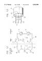
- FIG. 12is a schematic diagram of a thermocouple system having two sensor thermocouple wires and a composition-matched, common-lead thermocouple wire attached to a wire simulating a portion of a band electrode;
- FIG. 13is a diagram of a single band electrode showing the connection of two sensor thermocouple wires and a composition-matched, common-lead thermocouple wire.
- FIG. 1there is shown an ablation apparatus 10 in accordance with aspects of the present invention.
- the apparatus 10includes a power control system 12 that provides power or drive 14 to an electrode device 16.
- the power control system 12comprises a power generator 18 that may have any number of output channels through which it provides the power 14.
- the operation of the power generator 18is controlled by a controller 20 which outputs control signals 21 to the power generator 18.
- the controller 20monitors the power 14 provided by the power generator 18.
- the controller 20also receives temperature signals 22 from the electrode device 16. Based on the power 14 and temperature signals 22 the controller 20 adjusts the operation of the power generator 18.
- a backplate 24is located proximal to the biological site 26 opposite the site from the electrode device 16, and is connected by a backplate wire 28 to the power generator 18.
- the backplate 24is set at the reference level to the power provided to the electrodes, as discussed in detail below.
- the electrode device 16is typically part of a steerable EP catheter 30 capable of being percutaneously introduced into a biological site 26, e.g., the atrium or ventricle of the heart.
- the electrode device 16is shown in schematic form with the components drawn to more clearly illustrate the relationship between the components and the relationship between the components and the power control system 12.
- the catheter 30comprises a distal segment 34 and a handle 31 located outside the patient.
- a preferred embodiment of the electrode device 16includes twelve band electrodes 32 arranged in a substantially linear array along the distal segment 34 of the catheter 30.
- the electrode device 16may include a tip electrode 36.
- band electrodes 32are arranged so that there is space 38 between adjacent electrodes.
- the width of the band electrodes 32is 3 mm and the space 38 between the electrodes is 4 mm.
- the total length of the electrode device 16, as such,is approximately 8 cm.
- the arrangement of the band electrodes 32is not limited to a linear array and may take the form of other patterns.
- a substantially linear arrayis preferred for certain therapeutic procedures, such as treatment of atrial fibrillation, in which linear lesions of typically 4 to 8 cm in length are desired.
- a linear arrayis more easily carried by the catheter 30 and also lessens the size of the catheter.
- the band electrodes 32are formed of a material having a significantly higher thermal conductivity than that of the biological tissue 26. Possible materials include silver, gold, chromium, aluminum, molybdenum, tungsten, nickel, platinum, and platinum/10% iridium. Because of the difference in thermal conductivity between the electrodes 32 and the tissue 26, the electrodes 32 cool off more rapidly in the flowing fluids at the biological site. The power supplied to the electrodes 32 may be adjusted during ablation to allow for the cooling of the electrodes while at the same time allowing for the temperature of the tissue to build up so that ablation results.
- the electrodes 32are sized so that the surface area available for contact with fluid in the heart, e.g., blood, is sufficient to allow for efficient heat dissipation from the electrodes to the surrounding blood.
- the electrodes 32are 7 French (2.3 mm in diameter) with a length of 3 mm.
- the thickness of the band electrodes 32also affects the ability of the electrode to draw thermal energy away from the tissue it contacts.
- the electrodes 32are kept substantially thin so that the electrodes effectively draw energy away from the tissue without having to unduly increase the outer diameter of the electrode.
- the thickness of the band electrodesis 0.05 to 0.13 mm (0.002 to 0.005 inches).
- each band electrode 32has a temperature sensor 40 mounted to it.
- Each temperature sensor 40provides a temperature signal 22 to the controller 20 which is indicative of the temperature of the respective band electrode 32 at that sensor.
- a temperature sensor 40is mounted on every other band electrode 32.
- every other electrodehas two temperature sensors 40.
- FIG. 1which shows an embodiment having one temperature sensor for each electrode, there is shown a single power lead 15 for each electrode 32 to provide power to each electrode for ablation purposes and two temperature leads 23 for each temperature sensor 40 to establish the thermocouple effect.
- the drive wiremay comprise one of the thermocouple wires or may comprise a common wire for a plurality of thermocouples mounted on the same electrode.
- the inventorhereby incorporates by reference his pending application Ser. No. 09/072,800 entitled “Catheter Having Common Lead for Electrode and Sensor” filed May 5, 1998, and pending application Ser. No. 09/072,853 entitled “Electrode Having Non-Joined Thermocouple for Providing Multiple Temperature-Sensitive Junctions" filed this same day.
- FIGS. 2-1 and 2-2a block diagram of an ablation apparatus 10 and method in accordance with aspects of the invention is presented.
- a single channel of the power control system 12is depicted. This channel controls the application of power to a single electrode 32.
- a channelmay control a plurality or group of electrodes.
- a microprocessor 42which is part of the controller 20 (FIG. 1), provides a duty cycle control signal 44 to a duty cycle generator 45.
- the duty cycle generator 45receives the control signal 44 by an 8-bit latch 46.
- the latch 46provides an 8-bit signal 47 to a duty cycle comparator (“DCC”) 48.
- DCCduty cycle comparator
- the comparator 48compares the 8-bit signal 47 to a count from an 8-bit duty cycle counter 50 and if the count is the same, provides a duty cycle off signal 49 to the duty cycle gate 52.
- the gate 52is connected to a frequency source (“FS") 54, such as an oscillator that produces 500 kHz.
- FSfrequency source
- an 8-bit controlhas a period or time frame of 0.5 msec.
- the electrodeis in the off period only 0.25 msec.
- the period or time frame 78(FIG. 6) is lengthened by use of a prescalar 56 interposed between the frequency source 54 and the counter 50.
- the prescalar 56lengthens the period to 4 msec thus allowing for a 2 msec off period during a fifty-percent duty cycle. This results in a sufficient cooling time for the very thin band electrodes discussed above. Other lengths of the period may be used depending on the circumstances.
- a terminal count detector 58detects the last count of the period and sends a terminal count signal 59 to the gate 52 which resets the gate for continued output of the frequency source signal. This then begins the on period of the duty cycle and the counter 50 begins its count again.
- the duty cycleis set at fifty percent and the 8-bit latch is accordingly set to 128. In another embodiment, the duty cycle is set at ten percent.
- a programmable logic array (“PLA”) 60receives phase control signals 61 from the microprocessor 42 and controls the phase of the frequency source 54 accordingly.
- the PLA 60receives the terminal count signal 59 from the terminal count detector 58 and only permits phase changes after receiving that terminal count signal.
- the output signal from the gate 52 during the on period of the duty cycleis provided to a binary power amplifier (“BPA”) 62 that increases the signal to a higher level, in this case, 24 volts.
- BPAbinary power amplifier
- the amplified signalsare then filtered with a band pass filter (“BPF") 64 to convert the somewhat square wave to a sine wave.
- the band pass filter 64in one embodiment is centered at 500 kHz.
- the filtered signalis then provided to an isolated output transformer (“IOT”) 66 that amplifies the signal to a much higher level, for example 350 volts peak-to-peak.
- IOTisolated output transformer
- This signalis then sent to a relay interconnect (“RI”) 67 before it is provided as a power output signal OUTn 14 to an electrode 32 at the biological site to cause ablation.
- RIrelay interconnect
- the power output signal 14 from the isolated output transformer 66is monitored in one embodiment to determine the impedance at the electrode 32.
- a voltage and current monitor (“VCM") 68is used.
- the monitor signal 69is converted to digital form by an A-to-D converter (“ADC”) 70 and provided to the microprocessor 42.
- ADCA-to-D converter
- some or all of the electrodes 32may include a temperature sensor 40 (FIG. 1) that provides temperature signals 22 (FIG. 2-2 ) which are used to determine the temperature at the electrode 32.
- the power 14, in conjunction with the temperature signals 22,are used to determine the temperature at the electrode 32.
- Both the temperature signals 22 and the power 14pass through a temperature filter ("FL") 73 before being sent to the microprocessor 42.
- the temperature filter 73is contained in a printed circuit board separate from the controller 20 and contains its own processor. In either case, the filter 73 filters out any RF noise present in the power 14 so that the signal may be used for temperature monitoring purposes.
- the microprocessormonitors the power 14 and temperature signals 22 only during the off periods of the power 14 duty cycle. Accordingly, negligible RF noise is present in the power line and filtration is not necessary.
- the microprocessor 42may alter the duty cycle of the power 14 in response to either or both of the impedance or temperature signals.
- the temperature sensed and/or the determined impedancemay be displayed to an operator.
- the operatorin response may then manually control the duty cycle or other power parameters such as by rotating a knob mounted on a front panel of an instrument.
- a knob mounted on a front panel of an instrumentIn the case of a multiple channel instrument and catheter, as discussed below, multiple knobs may be provided in this manual arrangement for control over each channel.
- FIG. 3a multiple channel ablation apparatus is shown. Although only three complete channels are shown, the apparatus comprises many more as indicated by the successive dots. Those channels are not shown in FIG. 3 to preserve clarity of illustration.
- By providing different voltage levels between two electrodes 32 in an arraycurrent flows between those electrodes in a bipolar electrode approach.
- By setting the backplate 24 (FIG. 1)at a voltage level different from at least one of those electrodes 32, current flows between that electrode and the backplate.
- the current flow through the biological site 26can be more precisely controlled.
- One technique for setting different voltage levels between the electrodes 32is to maintain a phase difference between them in an AC approach. By setting the backplate 24 at the reference level, current flows between the electrodes 32 and the backplate.
- the single microprocessor 42which again is part of the controller 20 (FIG. 1), controls the duty cycle and the phase of each channel individually in this embodiment.
- Each channel showncomprises the same elements and each channel produces its own power output signal 14 (OUT1, OUT2, through OUTn where "n" is the total number of channels) on respective electrode leads (LEAD 1, LEAD 2, through LEAD n where "n" is the total number of leads) to the electrodes 32.
- This multi-channel approachpermits more individual control over each electrode.
- the duty cycle of the power applied to each electrodecan be individually controlled.
- One electrodemay have a ten percent duty cycle while another has a thirty percent duty cycle.
- the signalsas shown in FIGS. 4, 5, and 6, have alternating instances of peak power i.e., "on” periods 74, and very low power 76, i.e., "off” periods.
- the output power 14is a 500 kHz sine wave.
- the number of cycles of the sine wave contained within one on period 74has been substantially reduced in the drawing to emphasize the phase difference between the first and second output signals OUT1, OUT2.
- the voltage of each power signal 14 during an off period 76is substantially zero and during an on period 74 is approximately 350 volts peak-to-peak.
- the power OUT1 and OUT2also have a variable duty cycle for controlling the length of the on period 74 and the off-period 76 within a time frame 78 (see FIG. 6).
- the duty cycleis the ratio of the length of the on period 74 to the length of the entire time frame 78.
- the effective poweris the peak power times the duty cycle. Thus, a signal having a peak power of 100 watts and a 50% duty cycle has an effective power of 50 watts.
- the two power signals OUT1, OUT2are phased differently from each other.
- the phase angle of each power signalis set and controlled by the processor 42 and PLA 60.
- Each power signal OUT1 and OUT2has a respective phase angle and those phase angles differ between the two of them.
- the phase angle difference between the power OUT1 and 0UT2produces a voltage potential between the band electrodes 32 (FIG. 1) that receive the power. This voltage potential, in turn, induces current flow between the band electrodes 32.
- FIGS. 7A and 7BThe phase angle relationship of the power and the voltage potential produced as a function of time is shown in FIGS. 7A and 7B.
- Vvoltage amplitude of power
- FIG. 7Ashows first and second power OUT1 and OUT2 provided to first and second electrodes respectively having a phase angle difference ⁇ with OUT1 leading OUT2 by 132 degrees.
- FIG. 7Bshows the same power OUT1 and OUT2 but with the phase angles reversed where OUT2 is now leading OUT 1 by 132 degrees.
- FIGS. 8A through 8Eschematic diagrams of an embodiment of the ablation apparatus 10 of FIGS. 2-1 and 2-2 are presented in FIGS. 8B through 8E while FIG. 8A shows how FIGS. 8B through 8E should be oriented in relation to each other.
- the frequency source 54provides a signal 80, typically at 500 kHz with a phase angle controlled by the microprocessor 42 through the PLA 60, to the duty cycle generator 45.
- the duty cycle generator 45modulates the frequency source signal 80 to produce the selected duty cycle in accordance with the duty cycle control signal 44 as previously described.
- the duty cycle generator 45outputs two signals 82 and 84 to the binary power amplifier 62.
- a dual MOSFET driver U2receives the signals, converts their 5V level to a 12V level, and sends each to a transformer T2 which transforms the signals into 24 V peak-to-peak power.
- the 24V poweris then sent to a multi-state driver 86 which includes a configuration of FETs Q2, Q3, Q4, and Q5.
- a conducting state of the driver 86which is typically the on period 74 of the power, these FETs Q2 through Q5 conduct and forward the power to a bandpass filter 64 comprising a series LC network.
- a high-impedance state of the driver 86which is typically during the off period 76 of the power, the FETs Q2 through Q5 are nonconducting and no power is sent to the bandpass filter 64. Instead the FETs Q2 through Q5 present a high impedance load to any signals received through the electrode 32.
- the load impedance on the FETs Q2 through Q5 presented by the circuit following the FETs, the electrode, and the tissueis approximately 150 ⁇ but transformed through the output transformer T3, it presents a load impedance to the FETs Q2-Q5 of approximately 0.5 to 1 ⁇ .
- the FETsIn the off state, the FETs present an impedance of approximately 250 ⁇ which is large in comparison to the transformed load impedance of approximately 0.5 to 1 ⁇ . Therefore, very little power flows when the FETs are in the off state.
- the bandpass filter 64operates to shape the output signal provided by the binary amplifier 62 from a square wave to a sinusoidal wave.
- the filtered signal 85then passes to the isolated output section 66 where it is step-up transformed to 350 volt peak-to-peak sinusoidal power at T3.
- the poweris then split into two identical power signals OUT1A, OUT1B and provided to two or more respective band electrodes 32 on the output lines LEAD1A, LEAD1B.
- the isolated output section 66also includes relays 88 that may be individually opened to remove the power signals OUT1A, OUT1B from the electrode leads LEAD 1A, LEAD 1B when an alert condition is detected, such as high temperature or high impedance at the respective electrode 32. As previously mentioned these conditions are determined by the microprocessor 42 which receives signals indicative of the temperature and impedance at each of the band electrodes 32.
- the power from the isolated output section 66is monitored and representative signals are supplied to an RF voltage and current monitor 68 where in this case, the voltage and current of each output signal are measured to determine the impedance of the particular channel.
- the measured signalsare sent to an A-to-D converter 70 (FIG. 2-2) before being sent to the microprocessor 42 for impedance monitoring. If the impedance is above a threshold level indicative of blood clotting or boiling, the microprocessor 42 sends a signal to the duty cycle generator 45 to reduce or discontinue the duty cycle of the power OUT1A, OUT1B and thus lower the effective power delivered to the band electrodes 32.
- the temperature at the electrodes 32is determined by monitoring the power 14 and temperature signals 22 and measuring the voltage difference between the signals. As previously mentioned, in one embodiment of the invention, these signals pass through a filter 73 (FIG. 2-2) before being sent to the microprocessor 42. The voltage value is converted to a temperature and if the temperature is above a threshold level the duty cycle of the power 14 is reduced. In the case where a single lead is used to provide a signal which is used to determine the temperature as well as provide power to the electrode 32, the signal from the lead is received on temperature leads 87, 89 connected at the output side of the relays 88.
- the duty cycle of each electrode 32may be individually controlled by the microprocessor 42. As previously mentioned, based on the temperature at an electrode 32 and the current and voltage of the output signal provided to an electrode, the duty cycle of the output signal may be adjusted. For example, one electrode 32 may have a temperature requiring a duty cycle of ten percent, while another electrode may have a temperature which allows for a fifty percent duty cycle. In an embodiment in which every other electrode 32 has a temperature sensor 40, the electrodes are grouped in pairs with each electrode in the pair having the same duty cycle.
- the electrode device 16 and the backplate 24are positioned proximal the biological site 26 undergoing ablation such that the biological site is interposed between the electrode device and the backplate.
- the band electrodes 32(only one of which is indicated by a numeral 32 for clarity of illustration) of the electrode device 16 each receives power OUT1, OUT2, OUT3, OUT4 having a phase angle on LEAD 1 through LEAD 4.
- every other electrode 32receives the same phase angle. Therefore, the phase angle of electrode A equals the phase angle of electrode C and the phase angle of electrode B equals the phase angle of electrode D.
- the electrodes 32are formed into a linear array as shown.
- a thermocouple temperature sensor 40is located at each of the electrodes A, B, C, and D and uses the electrode power lead LEADS 1 through 4 as one of the sensor leads. The sensors 40 provide temperature sensor signals 22 for receipt by the power control system 12.
- alternate electrodes 32may be grouped together and each may receive the same power having the same phase angle and duty cycle. Another group or groups of electrodes 32 may be interspaced with the first group such that the electrodes of one group alternate with the electrodes of the other group or groups. Each electrode 32 in a particular group of electrodes has the same phase angle and duty cycle. For example, electrodes A and C may be connected to the same power while interspaced electrodes B and D may be connected to a different power output signal.
- the use of individual power signalsalso provides the ability to disable any combination of electrodes 32 and thereby effectively change the length of the electrode device 16.
- an electrode device 16 with twelve electrodes 32receives twelve power signals from a twelve channel power control system 12.
- the electrodes 32are 3 mm in length and are 4 mm apart. Accordingly, by disabling various electrodes, a virtual electrode of any length from 3 mm to 8 cm may be produced by the electrode device 16.
- the backplate 24is maintained at the reference voltage level in regard to the voltage level of the power OUT1 through OUTn.
- phase angle differencemay be adjusted to control the voltage potential between adjacent band electrodes 32 and thus to control the flow of current through the biological site 26.
- Vvoltage amplitude of power
- Vvoltage amplitude of power
- FIGS. 9A through 11Dillustrate various current flow patterns within a biological site.
- the depths and widths of the lesions depicted in FIGS. 9A through 11Dare not necessarily to scale or in scalar proportion to each other but are provided for clarity in discerning the differences between the various power application techniques.
- the phase difference between adjacent electrodes 32is zero degrees, no current flows between the electrodes in accordance with Eq. 2 above, and the apparatus operates in a unipolar fashion with the current flowing to the backplate 24 as shown in FIGS. 9A through 9D.
- the lesionsare discrete.
- the lesions 90are discontinuous in regard to each other.
- the apparatusWhen the phase difference between adjacent electrodes 32 is 180 degrees the apparatus operates in both a unipolar and bipolar fashion and the current flow pattern is as shown in FIG. 10A. With this phase difference, approximately twice as much current flows between adjacent band electrodes 32 than flows from the band electrodes to the backplate 24. The resulting lesion 92 is shallow but is continuous along the length of the electrode device 16. The continuity and shallow depth of the lesion 92 are illustrated in FIGS. 10B through 10D. Nevertheless, the lesion depth is still greater than that created by prior bipolar ablation methods alone.
- the phase angle of the powermay be adjusted in order to produce a lesion having different depth and continuity characteristics.
- other elements of the electrode device 16are considered.
- the width of the band electrodes 32 and the spacing between the electrodesare factors in selecting an optimum phase angle.
- the width of the band electrodesis 3 mm
- the spacing between the electrodesis 4 mm
- the electrodesreceive power which establish a phase difference of 132 degrees between adjacent electrodes.
- energyis applied to the biological tissue 26 during the on period of the duty cycle in an alternating unipolar-bipolar manner.
- a voltage potentialis established between the electrodes 32 and the backplate 24.
- currentflows through the tissue 26 between the electrodes 32 and the backplate 24.
- a voltage potentialis established between at least two of the electrodes 32 rather than between the electrodes and the backplate 24.
- currentflows through the tissue 26 between the electrodes 32.
- the voltage difference between the electrodes 32may be established by providing power with different phase angles to the electrodes as previously mentioned.
- some of the electrodes 32may be connected to a reference potential while others are maintained at a different voltage level.
- the continuity and depth of the lesion producedmay be controlled. For example, operating in the unipolar mode for one-fourth of the on period and in the bipolar mode for three-fourths of the on period produces a lesion having a continuity and depth similar to the lesion 94 illustrated in FIGS. 11B through 11D.
- FIGS. 8B through and 8Ethe following devices are shown:
- the transformer denoted by “T3”is a 1:12 turns ratio, single turn primary, step up transformer wound on a TDK core PC50EER23Z.
- the band electrodes 32generate a heating pattern in the tissue by transmitting RF power into the tissue.
- the power supplied to the band electrodes 32is typically increased in order to increase the ablation volume until either an impedance change is noticed due to the onset of clotting or the temperature limit set for the electrode is reached.
- the effective power delivered to the band electrodes 32is reduced by reducing the duty cycle of the power signal in this embodiment.
- the band electrodes 32are designed to heat a volume of tissue to an ablation temperature while at the same time assuring that the peak temperature of the band electrodes is controlled so that clotting does not foul the electrode surface and blood boiling does not occur.
- each of the band electrodes 32is formed from a biocompatible material having a high thermal conductivity. It is preferred that the materials exhibit substantially the same thermal and electrical conductivity properties.
- the following metalsare provided for example in descending order of electrical conductivity as measured using the International Annealed Copper Standard (IACS): silver, gold, chromium, aluminum, molybdenum, tungsten, nickel, platinum, and platinum/10% iridium.
- that materialis substantially pure platinum.
- Pure platinumis preferred over platinum/10% iridium, which is commonly used in electrophysiology catheters, because it has been found to produce larger lesions with lesser incidence of impedance rise at the electrode/tissue interface.
- Pure platinumalso has a more reliable thermoelectric performance.
- the electrodesare formed using a cold work process as is well known to those skilled in the art of materials processing. The raw platinum is cold worked to a hardness greater than that which would be achieved by an annealing process and is preferably at least 50% cold worked.
- the band electrodes 32are sized so that a large surface area is available for contact with the fluid in the heart for dissipating heat to the fluid around the electrode and thereby cooling the electrode. Also, the thickness of the band electrodes 32 is selected so that the electrodes effectively draw heat energy away from the target tissue for cooling purposes without unduly increasing the outside diameter of the electrode device.
- first electrically conductive sensor lead 100, second electrically conductive sensor lead 102, and electrically conductive common lead 101are connected independently to the band electrode 32 at two sensor junctions 104 and 106, and a common junction 105 respectively. Each of these junctions are separate from each other.
- These three electrically conductive members 100, 101, and 102form the leads, i.e., or "legs" of what is essentially two thermocouples.
- thermocouplesBecause of the separation between the locations at which the leads are attached to the inside surface of the band electrode, the portions 126 and 127 of the band electrode 32 between the connection points 104, 105, and 106 become part of the thermocouples and, in effect, serve as a large thermocouple bead.
- a temperature-dependent voltageAssociated with two of the junctions 104, 106 is a temperature-dependent voltage. This voltage is produced by the interface between two dissimilar metals and fluctuates in accordance with the temperature of the junction.
- a conductive lead 108is electrically connected to each sensor lead 100, 102 and the common lead 101 at a reference junction 110.
- a voltmeter 112is disposed across the conductive lead 108 connected to first sensor lead 100 and the conductive lead 108 connected to the common lead 101 to measure the temperature-dependent voltage developed in the thermocouple formed by sensor lead 100, common lead 101, and thermocouple bead 127.
- a voltmeter 112is disposed across the conductive lead 108 connected to second sensor lead 102 and the conductive lead 108 connected to the common lead 101 to measure the temperature-dependent voltage developed in the thermocouple formed by sensor lead 102, common lead 101, and thermocouple bead 126.
- the reference-junction lead 108is preferably made of the same material as the first and second sensor leads 100 and 102.
- the reference junction 110 and the leads for use in connection to the voltmeterare located in the handle 31 of the catheter and are therefore outside the patient.
- the reference junctions 110 and conductive leads 108are omitted and, as explained below, the reference temperature is assumed to be room temperature.
- FIGS. 12 and 13depict only two sensor leads 100 and 102 it is possible to include a larger number of sensor leads positioned around the circumference of the band electrode 32.
- Each such sensor leadwould form, in combination with the single common lead 101 and the thermocouple bead formed by the portion of the band electrode 32 between the sensor lead and common lead, a separate thermocouple.
- Each of these thermocouplesprovide a temperature-dependent voltage indicative of the temperature at the junction where the sensor lead is connected to the band electrode 32.
- Conductive leads 100, 102, 108are connected to a voltmeter 112 located within the controller 20 (FIG. 1).
- the voltmeter 112(FIG. 12) provides voltage readings which are related to the temperatures at the various junctions 104, 106, and 110.
- the resulting voltage output V ab measured by each voltmeter 112is expressed by the following general equation:
- ⁇ acSeebeck coefficient for the first sensor lead 100 material and the band material or for the second sensor lead 102 material and the band material
- ⁇ bcSeebeck coefficient for the common lead 101 material and the band material
- T atemperature at the first sensor lead/electrode junction 104 or at the second sensor lead/electrode junction 106
- T btemperature at the common lead/electrode junction 105
- T reftemperature at the reference junction 110
- T ref and the two Seebeck coefficients, ⁇ ac and ⁇ bcare typically known for the system at hand.
- the reference junction 110is a controlled temperature junction which is normally included in order to correct for extraneous voltages due to dissimilar metal junctions at the voltmeter terminals.
- the temperatureis known to be room temperature, or approximately 22 degrees C. (72 degrees F.).
- the Seebeck coefficientsare assumed to be constant over the range of temperatures typically encountered in cardiac ablation.
- the material of the common lead 101is chosen such that the temperature-dependent voltage produced at the common junction 105 is substantially zero. This is preferably done by forming the common lead 101 of the same material as the band electrode 32 or alternatively by forming the common lead of a material having a thermoelectric output very similar to that of the band-electrode material.
- the electrode 32is described as having a "composition-matched" common lead 101.
- the band electrode 32 and the common lead 101are formed of substantially pure platinum.
- the band electrode 32is formed of substantially pure platinum and the common lead is formed of a copper/nickel alloy containing approximately 1-2% nickel, which is known to those skilled in the art as "alloy 11." In addition to its platinum like thermoelectric properties, alloy 11 is also preferred because it is a low cost alternative to pure platinum leads. In either embodiment, ⁇ bc approximately equals zero and Eq. 5 reduces to:
- the materials of the first and second sensor leads 100, 102are chosen such that the magnitude of the Seebeck coefficients of the materials relative to the band electrode 32 material is large. In order to increase the voltage output and improve temperature measurement resolution, preferably, the material of the first and second sensor leads 100, 102 is chosen such that the ratio of the magnitude of the Seebeck coefficient of the sensor lead 100, 102 material relative to the band electrode 32 material and the magnitude of the Seebeck coefficient of the common lead 101 material relative to the band electrode 32 is at least ten to one. In one preferred embodiment, the first and second sensor leads 100 and 102 were formed of constantan. Constantan is preferred because it has a large Seebeck coefficient relative to platinum and it is a commercially available alloy produced to tight thermoelectric property tolerances.
- These legs 100, 102are connected to a band electrode 32 formed of substantially pure platinum.
- a band electrode 32formed of substantially pure platinum.
- the following tableprovides approximate Seebeck coefficients (averaged over the temperature range of from zero to 100° C.) for a variety of different metals and alloys.
- the arrangement shown in FIGS. 12 and 13provides for multiple temperature-sensitive locations, i.e., junctions 104, 106, on the band electrode 32 using only three thermocouple wires 100, 101, 102, as opposed to two thermocouple pairs, i.e., four wires, thus resulting in a considerable saving of space in the ablation catheter.
- a band electrode 32is shown having a composition-matched common lead 101 and two sensor leads 100, 102 at the inside surface of the band.
- Each lead 100, 101 and 102is separately connected to the band electrode 32 to form the three junctions 104, 105, and 106.
- the two sensor leads 100, 102may be located anywhere on the band 32 they are preferably positioned approximately 60 degrees apart around the circumference of the band electrode.
- the common lead 101may be positioned anywhere on the band electrode 32.
- a separate power leadconducts power to the band electrode 32 to impart ablation energy to the biological target tissue.
- four leadsare used to provide power and to provide temperature sensing in two locations as opposed to five leads which would be required if each thermocouple had two leads.
- the common lead 101is also used to conduct power to the band electrode 32 to impart ablation energy to the biological target tissue.
- the common lead 101is also used to conduct power to the band electrode 32 to impart ablation energy to the biological target tissue.
- the common lead 101only three leads 100, 101, 102 are used to provide power and to sense in two locations at the band electrode 32 rather than five leads as required by an electrode employing conventional thermocouples. This can result in a substantial savings in size because of the existence of fewer leads to be housed by the catheter.
- thirty-six leadsare required.
- thermocouple voltagesare typically on the order of 0.001 mV to 0.10 mV per degree C.
- the power conducted on the common lead 101could interfere with the detection of the temperature-dependent voltages generated at the sensor junctions 104, 106. Filtration could be used to separate the DC thermocouple signals from the drive or power signals. Such an arrangement is shown in FIG. 2.
- the controller 20monitors the leads 100, 102 for thermocouple signals only during the off-period 76 of the duty cycle 78, for example, as shown in FIG. 6. During this off-period, no power is being applied to the band electrode 32 over the common electrode lead 101 and there is less chance for interference with the thermocouple signals produced by the band electrode 32 and conducted on both leads 100, 102. Thus, the temperatures may be measured briefly without electrical interference.
- the inventionmay also be applied to ablation catheters employing alternate sources of energy for ablation, such as ultrasound or microwave energy.
- the inventionmay also be applied to any system in which monitoring temperature is important and where the position of temperature important to the monitoring process.
Landscapes
- Health & Medical Sciences (AREA)
- Life Sciences & Earth Sciences (AREA)
- Engineering & Computer Science (AREA)
- Physics & Mathematics (AREA)
- Surgery (AREA)
- Nuclear Medicine, Radiotherapy & Molecular Imaging (AREA)
- Animal Behavior & Ethology (AREA)
- General Health & Medical Sciences (AREA)
- Public Health (AREA)
- Veterinary Medicine (AREA)
- Biomedical Technology (AREA)
- Cardiology (AREA)
- Radiology & Medical Imaging (AREA)
- Plasma & Fusion (AREA)
- Otolaryngology (AREA)
- General Physics & Mathematics (AREA)
- Heart & Thoracic Surgery (AREA)
- Medical Informatics (AREA)
- Molecular Biology (AREA)
- Surgical Instruments (AREA)
- Electrotherapy Devices (AREA)
- Measuring Temperature Or Quantity Of Heat (AREA)
Abstract
Description
______________________________________ Device Part No. Manufacturer ______________________________________ U1 GAL6002B Lattice U2 numerous Q1 numerous Q2, Q3, Q4, Q5 1RFZ44N numerous Q7, Q8, Q9 MPF6601 numerous R3, R5 1Ω numerous T1, T4 CMI-4810 Corona Magnetics, Inc. T2 GFS Manufacturing T5 Corona Magnetics, Inc. ______________________________________
V.sub.ab =α.sub.ac (T.sub.a -T.sub.ref)-α.sub.bc (T.sub.b -T.sub.ref) (Eq. 5)
V.sub.ab =α.sub.ac (T.sub.a -T.sub.ref) (Eq. 6)
______________________________________ SEEBECK COEFFICIENT (mV/C) vs. METAL OR ALLOY PURE PLATINUM ______________________________________ Bismuth -0.0734 Constantan -0.0351 Nickel -0.0148 Cobalt -0.0133 Alumel -0.0129 Mercury -0.0060 Palladium -0.0057 Calcium -0.0051 Gold-chromium -0.0017 Thorium -0.0013Platinum 0Alloy 11 +0.0013 Tantalum +0.0033 Aluminum +0.0042 Tin +0.0042 Lead +0.0044 Magnesium +0.0044 Stainless steel, 18-8 +0.0044 Solder 96.5Sn/3.5Ag +0.0045 Solder 50Sn/50Pb +0.0046 Phosphor bronze +0.0055 Thallium +0.0058 Yellow brass +0.0060 Manganin +0.0061 Iridium +0.0065 Copper-beryllium +0.0067 Indium +0.0069 Rhodium +0.0070 Silver +0.0074 Copper +0.0076 Zinc +0.0076 Gold +0.0078 60Ni/24Fe/16Cr +0.0085 Cadmium +0.0090 Tungsten +0.0112 Cerium +0.0114 80Ni/20Cr +0.0114 Spring steel +0.0132 Molybdenum +0.0145 Lithium +0.0182 Iron +0.0189 Chromel P +0.0281 Antimony +0.0489 ______________________________________
Claims (25)
Priority Applications (9)
| Application Number | Priority Date | Filing Date | Title |
|---|---|---|---|
| US09/072,801US6042580A (en) | 1998-05-05 | 1998-05-05 | Electrode having composition-matched, common-lead thermocouple wire for providing multiple temperature-sensitive junctions |
| PCT/US1999/009494WO1999056645A2 (en) | 1998-05-05 | 1999-04-30 | Electrode having multiple temperature-sensitive junctions |
| JP2000546682AJP2002513618A (en) | 1998-05-05 | 1999-04-30 | Electrodes with multiple temperature-sensitive junctions |
| CA002327437ACA2327437A1 (en) | 1998-05-05 | 1999-04-30 | Electrode having multiple temperature-sensitive junctions |
| EP99920216AEP1076521A2 (en) | 1998-05-05 | 1999-04-30 | Electrode having multiple temperature-sensitive junctions |
| US09/502,179US6309385B1 (en) | 1998-05-05 | 2000-02-10 | Electrode having composition-matched, common-lead thermocouple wire for providing multiple temperature-sensitive junctions |
| US09/515,382US6312425B1 (en) | 1998-05-05 | 2000-02-29 | RF ablation catheter tip electrode with multiple thermal sensors |
| US09/948,334US6616657B2 (en) | 1998-05-05 | 2001-09-06 | RF ablation catheter tip electrode with multiple thermal sensors |
| US09/949,528US6582425B2 (en) | 1998-05-05 | 2001-09-07 | Electrode having composition-matched, common-lead thermocouple wire for providing multiple temperature-sensitive junctions |
Applications Claiming Priority (1)
| Application Number | Priority Date | Filing Date | Title |
|---|---|---|---|
| US09/072,801US6042580A (en) | 1998-05-05 | 1998-05-05 | Electrode having composition-matched, common-lead thermocouple wire for providing multiple temperature-sensitive junctions |
Related Child Applications (2)
| Application Number | Title | Priority Date | Filing Date |
|---|---|---|---|
| US09/502,179DivisionUS6309385B1 (en) | 1998-05-05 | 2000-02-10 | Electrode having composition-matched, common-lead thermocouple wire for providing multiple temperature-sensitive junctions |
| US09/515,382Continuation-In-PartUS6312425B1 (en) | 1998-05-05 | 2000-02-29 | RF ablation catheter tip electrode with multiple thermal sensors |
Publications (1)
| Publication Number | Publication Date |
|---|---|
| US6042580Atrue US6042580A (en) | 2000-03-28 |
Family
ID=22109839
Family Applications (3)
| Application Number | Title | Priority Date | Filing Date |
|---|---|---|---|
| US09/072,801Expired - LifetimeUS6042580A (en) | 1998-05-05 | 1998-05-05 | Electrode having composition-matched, common-lead thermocouple wire for providing multiple temperature-sensitive junctions |
| US09/502,179Expired - LifetimeUS6309385B1 (en) | 1998-05-05 | 2000-02-10 | Electrode having composition-matched, common-lead thermocouple wire for providing multiple temperature-sensitive junctions |
| US09/949,528Expired - LifetimeUS6582425B2 (en) | 1998-05-05 | 2001-09-07 | Electrode having composition-matched, common-lead thermocouple wire for providing multiple temperature-sensitive junctions |
Family Applications After (2)
| Application Number | Title | Priority Date | Filing Date |
|---|---|---|---|
| US09/502,179Expired - LifetimeUS6309385B1 (en) | 1998-05-05 | 2000-02-10 | Electrode having composition-matched, common-lead thermocouple wire for providing multiple temperature-sensitive junctions |
| US09/949,528Expired - LifetimeUS6582425B2 (en) | 1998-05-05 | 2001-09-07 | Electrode having composition-matched, common-lead thermocouple wire for providing multiple temperature-sensitive junctions |
Country Status (5)
| Country | Link |
|---|---|
| US (3) | US6042580A (en) |
| EP (1) | EP1076521A2 (en) |
| JP (1) | JP2002513618A (en) |
| CA (1) | CA2327437A1 (en) |
| WO (1) | WO1999056645A2 (en) |
Cited By (70)
| Publication number | Priority date | Publication date | Assignee | Title |
|---|---|---|---|---|
| WO2001080756A1 (en)* | 2000-04-27 | 2001-11-01 | Medtronic, Inc. | System and method for assessing transmurality of ablation lesions |
| WO2001082812A1 (en)* | 2000-04-27 | 2001-11-08 | Medtronic, Inc. | Vibration sensitive ablation apparatus and method |
| WO2001080755A3 (en)* | 2000-04-27 | 2002-01-10 | Medtronic Inc | Suction stabilized epicardial ablation devices |
| US6511478B1 (en)* | 2000-06-30 | 2003-01-28 | Scimed Life Systems, Inc. | Medical probe with reduced number of temperature sensor wires |
| WO2002077774A3 (en)* | 2001-03-27 | 2003-04-17 | Uab Research Foundation | Electrophysiologic measure of endpoints for ablation lesions created in fibrillating substrates |
| US6558378B2 (en)* | 1998-05-05 | 2003-05-06 | Cardiac Pacemakers, Inc. | RF ablation system and method having automatic temperature control |
| US20030167081A1 (en)* | 2002-03-01 | 2003-09-04 | Cardiac Pacemakers, Inc. | Coronary sinus lead with thermal sensor and method therefor |
| US20050033137A1 (en)* | 2002-10-25 | 2005-02-10 | The Regents Of The University Of Michigan | Ablation catheters and methods for their use |
| US6945417B2 (en)* | 1998-02-26 | 2005-09-20 | Becton, Dickinson And Company | Resealable medical transfer set |
| US20050251133A1 (en)* | 2000-04-27 | 2005-11-10 | Medtronic, Inc. | Suction stabilized epicardial ablation devices |
| US20050251132A1 (en)* | 2002-10-25 | 2005-11-10 | Regents Of The University Of Michigan | Ablation catheters |
| US20060106375A1 (en)* | 2004-11-15 | 2006-05-18 | Werneth Randell L | Ablation system with feedback |
| US20060111700A1 (en)* | 2004-11-24 | 2006-05-25 | Ablation Frontiers, Inc. | Atrial ablation catheter and method of use |
| US20060111701A1 (en)* | 2004-11-24 | 2006-05-25 | Ablation Frontiers, Inc. | Atrial ablation catheter adapted for treatment of septal wall arrhythmogenic foci and method of use |
| US20060189971A1 (en)* | 1995-11-22 | 2006-08-24 | Arthrocare Corporation | Systems and methods for electrosurgical treatment of fasciitis |
| US20070083193A1 (en)* | 2005-08-22 | 2007-04-12 | Werneth Randell L | User interface for tissue ablation system |
| US20070083195A1 (en)* | 2005-07-11 | 2007-04-12 | Werneth Randell L | Low power tissue ablation system |
| US20070100390A1 (en)* | 2000-10-17 | 2007-05-03 | Asthmatx, Inc. | Modification of airways by application of energy |
| US20080021447A1 (en)* | 1998-08-11 | 2008-01-24 | Arthrocare Corporation | Instrument for electrosurgical tissue treatment |
| US20080234673A1 (en)* | 2007-03-20 | 2008-09-25 | Arthrocare Corporation | Multi-electrode instruments |
| US20080281312A1 (en)* | 2007-05-11 | 2008-11-13 | Ablation Frontiers, Inc. | Ablation Therapy System and Method for Treating Continuous Atrial Fibrillation |
| US20090030411A1 (en)* | 2004-10-14 | 2009-01-29 | Werneth Randell L | Ablation catheter |
| US20100042095A1 (en)* | 2008-08-13 | 2010-02-18 | Robert Bigley | Systems and methods for screen electrode securement |
| US7850685B2 (en) | 2005-06-20 | 2010-12-14 | Medtronic Ablation Frontiers Llc | Ablation catheter |
| US20110152854A1 (en)* | 2009-12-23 | 2011-06-23 | Assaf Govari | Sensing contact of ablation catheter using differential temperature measurements |
| GB2479969A (en)* | 2010-04-30 | 2011-11-02 | Arthrocare Corp | Electrosurgical system and method having enhanced temperature measurement |
| US8317786B2 (en) | 2009-09-25 | 2012-11-27 | AthroCare Corporation | System, method and apparatus for electrosurgical instrument with movable suction sheath |
| US8323279B2 (en) | 2009-09-25 | 2012-12-04 | Arthocare Corporation | System, method and apparatus for electrosurgical instrument with movable fluid delivery sheath |
| US8355799B2 (en) | 2008-12-12 | 2013-01-15 | Arthrocare Corporation | Systems and methods for limiting joint temperature |
| US20130231611A1 (en)* | 2006-01-17 | 2013-09-05 | Endymed Medical Ltd. | Electrosurgical Methods and Devices Employing Phase-Controlled Radiofrequency Energy |
| US8652129B2 (en) | 2008-12-31 | 2014-02-18 | Medtronic Ardian Luxembourg S.A.R.L. | Apparatus, systems, and methods for achieving intravascular, thermally-induced renal neuromodulation |
| US8728075B2 (en) | 2010-04-26 | 2014-05-20 | Medtronic Ardian Luxembourg S.A.R.L. | Multi-directional deflectable catheter apparatuses, systems, and methods for renal neuromodulation |
| US20140163542A1 (en)* | 2012-12-11 | 2014-06-12 | Alcon Research, Ltd. | System and procedure for enhancing ocular drainage |
| US8774913B2 (en) | 2002-04-08 | 2014-07-08 | Medtronic Ardian Luxembourg S.A.R.L. | Methods and apparatus for intravasculary-induced neuromodulation |
| US9125661B2 (en) | 2002-04-08 | 2015-09-08 | Medtronic Ardian Luxembourg S.A.R.L. | Methods and apparatus for renal neuromodulation |
| US9131978B2 (en) | 2002-04-08 | 2015-09-15 | Medtronic Ardian Luxembourg S.A.R.L. | Methods for bilateral renal neuromodulation |
| US9283374B2 (en) | 2012-11-05 | 2016-03-15 | Boston Scientific Scimed, Inc. | Devices and methods for delivering energy to body lumens |
| US9592086B2 (en) | 2012-07-24 | 2017-03-14 | Boston Scientific Scimed, Inc. | Electrodes for tissue treatment |
| US9597142B2 (en) | 2014-07-24 | 2017-03-21 | Arthrocare Corporation | Method and system related to electrosurgical procedures |
| US9649148B2 (en) | 2014-07-24 | 2017-05-16 | Arthrocare Corporation | Electrosurgical system and method having enhanced arc prevention |
| US9827437B2 (en) | 2006-01-17 | 2017-11-28 | Endymed Medical Ltd | Skin treatment devices and methods |
| US20170347896A1 (en)* | 2016-06-02 | 2017-12-07 | Biosense Webster (Israel) Ltd. | Balloon catheter and related impedance-based methods for detecting occlusion |
| US9844682B2 (en) | 2006-01-17 | 2017-12-19 | Endymed Medical Ltd. | Skin treatment devices and methods |
| US9993178B2 (en) | 2016-03-15 | 2018-06-12 | Epix Therapeutics, Inc. | Methods of determining catheter orientation |
| US10166062B2 (en) | 2014-11-19 | 2019-01-01 | Epix Therapeutics, Inc. | High-resolution mapping of tissue with pacing |
| US10231779B2 (en) | 2014-11-19 | 2019-03-19 | Epix Therapeutics, Inc. | Ablation catheter with high-resolution electrode assembly |
| CN110075423A (en)* | 2014-02-07 | 2019-08-02 | 波士顿科学神经调制公司 | Temperature sensing circuit for implantable medical device |
| US10638976B2 (en) | 2016-04-28 | 2020-05-05 | Biosense Webster (Israel) Ltd | Method of constructing irrigated balloon catheter |
| US10653480B2 (en) | 2016-04-28 | 2020-05-19 | Biosense Webster (Israel) Ltd. | Method for constructing irrigated balloon catheter with flexible circuit electrode assembly |
| US10888373B2 (en) | 2017-04-27 | 2021-01-12 | Epix Therapeutics, Inc. | Contact assessment between an ablation catheter and tissue |
| US10976204B2 (en)* | 2018-03-07 | 2021-04-13 | Rosemount Inc. | Heat flux sensor with improved heat transfer |
| US20210267671A1 (en)* | 2015-11-20 | 2021-09-02 | St. Jude Medical, Cardiology Division, Inc. | Multi-electrode ablator tip having dual-mode, omni-directional feedback capabilities |
| USD968422S1 (en) | 2019-05-31 | 2022-11-01 | Biosense Webster (Israel) Ltd. | Display screen with transitional graphical user interface |
| USD968421S1 (en) | 2019-05-31 | 2022-11-01 | Biosense Webster (Israel) Ltd. | Display screen with a graphical user interface |
| USD969138S1 (en) | 2019-05-31 | 2022-11-08 | Biosense Webster (Israel) Ltd. | Display screen with a graphical user interface |
| US11957852B2 (en) | 2021-01-14 | 2024-04-16 | Biosense Webster (Israel) Ltd. | Intravascular balloon with slidable central irrigation tube |
| US11963715B2 (en) | 2016-11-23 | 2024-04-23 | Biosense Webster (Israel) Ltd. | Balloon-in-balloon irrigation balloon catheter |
| US11974803B2 (en) | 2020-10-12 | 2024-05-07 | Biosense Webster (Israel) Ltd. | Basket catheter with balloon |
| US12029545B2 (en) | 2017-05-30 | 2024-07-09 | Biosense Webster (Israel) Ltd. | Catheter splines as location sensors |
| US12042246B2 (en) | 2016-06-09 | 2024-07-23 | Biosense Webster (Israel) Ltd. | Multi-function conducting elements for a catheter |
| US12102781B2 (en) | 2018-06-29 | 2024-10-01 | Biosense Webster (Israel) Ltd. | Reinforcement for irrigated electrophysiology balloon catheter with flexible-circuit electrodes |
| US12114905B2 (en) | 2021-08-27 | 2024-10-15 | Biosense Webster (Israel) Ltd. | Reinforcement and stress relief for an irrigated electrophysiology balloon catheter with flexible-circuit electrodes |
| US12137967B2 (en) | 2019-11-12 | 2024-11-12 | Biosense Webster (Israel) Ltd. | Accurate positioning and shape visualization of balloon catheter ablation tags |
| US12161400B2 (en) | 2019-10-04 | 2024-12-10 | Biosense Webster (Israel) Ltd. | Identifying pulmonary vein occlusion by dimension deformations of balloon catheter |
| US12186013B2 (en) | 2021-02-18 | 2025-01-07 | Biosense Webster (Israel) Ltd. | Detection of balloon catheter tissue contact using optical measurement |
| US12239364B2 (en) | 2020-10-07 | 2025-03-04 | Biosense Webster (Israel) Ltd. | Printed proximal electrodes of an expandable catheter for use as a common electrode |
| US20250107839A1 (en)* | 2022-03-01 | 2025-04-03 | Gyrus Acmi, Inc. D/B/A Olympus Surgical Technologies America | Feedback control in electrosurgical systems |
| US12268436B2 (en) | 2018-09-14 | 2025-04-08 | Biosense Webster (Israel) Ltd. | Systems and methods of ablating cardiac tissue |
| US12369975B2 (en) | 2019-09-12 | 2025-07-29 | Biosense Webster (Israel) Ltd. | Balloon catheter with force sensor |
| US12369974B2 (en) | 2019-10-10 | 2025-07-29 | Biosense Webster (Israel) Ltd. | Touch indication of balloon-catheter ablation electrode via balloon surface temperature measurement |
Families Citing this family (79)
| Publication number | Priority date | Publication date | Assignee | Title |
|---|---|---|---|---|
| US6161543A (en) | 1993-02-22 | 2000-12-19 | Epicor, Inc. | Methods of epicardial ablation for creating a lesion around the pulmonary veins |
| US7052493B2 (en)* | 1996-10-22 | 2006-05-30 | Epicor Medical, Inc. | Methods and devices for ablation |
| US6840936B2 (en) | 1996-10-22 | 2005-01-11 | Epicor Medical, Inc. | Methods and devices for ablation |
| US6311692B1 (en)* | 1996-10-22 | 2001-11-06 | Epicor, Inc. | Apparatus and method for diagnosis and therapy of electrophysiological disease |
| US6805128B1 (en) | 1996-10-22 | 2004-10-19 | Epicor Medical, Inc. | Apparatus and method for ablating tissue |
| US6719755B2 (en)* | 1996-10-22 | 2004-04-13 | Epicor Medical, Inc. | Methods and devices for ablation |
| US8709007B2 (en) | 1997-10-15 | 2014-04-29 | St. Jude Medical, Atrial Fibrillation Division, Inc. | Devices and methods for ablating cardiac tissue |
| US6042580A (en) | 1998-05-05 | 2000-03-28 | Cardiac Pacemakers, Inc. | Electrode having composition-matched, common-lead thermocouple wire for providing multiple temperature-sensitive junctions |
| US6312425B1 (en) | 1998-05-05 | 2001-11-06 | Cardiac Pacemakers, Inc. | RF ablation catheter tip electrode with multiple thermal sensors |
| US8308719B2 (en)* | 1998-09-21 | 2012-11-13 | St. Jude Medical, Atrial Fibrillation Division, Inc. | Apparatus and method for ablating tissue |
| EP1207788A4 (en) | 1999-07-19 | 2009-12-09 | St Jude Medical Atrial Fibrill | Apparatus and method for ablating tissue |
| US20070282324A1 (en)* | 1999-07-19 | 2007-12-06 | Matthias Vaska | Apparatus and method for diagnosis and therapy of electrophysiological disease |
| US7281492B2 (en)* | 2002-04-01 | 2007-10-16 | Advanced Lighting Technologies, Inc. | System and method for generating a discharge in gases |
| CA2508800A1 (en) | 2002-12-11 | 2004-06-24 | Proteus Biomedical, Inc. | Method and system for monitoring and treating hemodynamic parameters |
| WO2004066814A2 (en)* | 2003-01-24 | 2004-08-12 | Proteus Biomedical Inc. | Method and system for remote hemodynamic monitoring |
| US7200439B2 (en) | 2003-01-24 | 2007-04-03 | Proteus Biomedical, Inc. | Method and apparatus for enhancing cardiac pacing |
| JP4465349B2 (en)* | 2003-01-24 | 2010-05-19 | プロテウス バイオメディカル インコーポレイテッド | Method and system for measuring cardiac parameters |
| EP1614004B1 (en)* | 2003-03-25 | 2012-10-31 | Molecular Imprints, Inc. | Positive tone bi-layer imprint lithography method and compositions therefor |
| AU2004235739B2 (en) | 2003-05-01 | 2010-06-17 | Covidien Ag | Method and system for programming and controlling an electrosurgical generator system |
| WO2005089473A2 (en)* | 2004-03-18 | 2005-09-29 | Advanced Lighting Technologies, Inc. | Method for generating a discharge in high pressure gases |
| WO2006029090A2 (en)* | 2004-09-02 | 2006-03-16 | Proteus Biomedical, Inc. | Methods and apparatus for tissue activation and monitoring |
| EP1871470A4 (en) | 2005-03-31 | 2011-06-01 | Proteus Biomedical Inc | Automated optimization of multi-electrode pacing for cardiac resynchronization |
| US8932208B2 (en) | 2005-05-26 | 2015-01-13 | Maquet Cardiovascular Llc | Apparatus and methods for performing minimally-invasive surgical procedures |
| US20060271035A1 (en)* | 2005-05-27 | 2006-11-30 | Cardima, Inc. | Bipolar tissue dessication system and method |
| US20090299447A1 (en)* | 2005-07-01 | 2009-12-03 | Marc Jensen | Deployable epicardial electrode and sensor array |
| WO2007021804A2 (en) | 2005-08-12 | 2007-02-22 | Proteus Biomedical, Inc. | Evaluation of depolarization wave conduction velocity |
| JP2009521276A (en)* | 2005-12-22 | 2009-06-04 | プロテウス バイオメディカル インコーポレイテッド | Implantable integrated circuit |
| US8003879B2 (en) | 2006-04-26 | 2011-08-23 | Cardiac Pacemakers, Inc. | Method and apparatus for in vivo thermoelectric power system |
| US8538529B2 (en)* | 2006-04-26 | 2013-09-17 | Cardiac Pacemakers, Inc. | Power converter for use with implantable thermoelectric generator |
| US8039727B2 (en)* | 2006-04-26 | 2011-10-18 | Cardiac Pacemakers, Inc. | Method and apparatus for shunt for in vivo thermoelectric power system |
| US8257414B2 (en)* | 2006-11-28 | 2012-09-04 | Stryker Corporation | Thermal pumps with features |
| US9861424B2 (en) | 2007-07-11 | 2018-01-09 | Covidien Lp | Measurement and control systems and methods for electrosurgical procedures |
| US8152800B2 (en) | 2007-07-30 | 2012-04-10 | Vivant Medical, Inc. | Electrosurgical systems and printed circuit boards for use therewith |
| US7645142B2 (en)* | 2007-09-05 | 2010-01-12 | Vivant Medical, Inc. | Electrical receptacle assembly |
| US8747398B2 (en) | 2007-09-13 | 2014-06-10 | Covidien Lp | Frequency tuning in a microwave electrosurgical system |
| WO2009045265A1 (en) | 2007-10-05 | 2009-04-09 | Maquet Cardiovascular, Llc | Devices and methods for minimally-invasive surgical procedures |
| US8473069B2 (en) | 2008-02-28 | 2013-06-25 | Proteus Digital Health, Inc. | Integrated circuit implementation and fault control system, device, and method |
| US8662746B2 (en)* | 2008-08-01 | 2014-03-04 | Siemens, Energy Inc. | Turbine component instrumented to provide thermal measurements |
| WO2010065465A2 (en)* | 2008-12-02 | 2010-06-10 | Proteus Biomedical, Inc. | Analyzer compatible communication protocol |
| EP2414036A4 (en)* | 2009-04-02 | 2013-02-20 | Proteus Digital Health Inc | Method and apparatus for implantable lead |
| WO2010126503A1 (en)* | 2009-04-29 | 2010-11-04 | Proteus Biomedical, Inc. | Methods and apparatus for leads for implantable devices |
| WO2011011736A2 (en) | 2009-07-23 | 2011-01-27 | Proteus Biomedical, Inc. | Solid-state thin film capacitor |
| US10828100B2 (en) | 2009-08-25 | 2020-11-10 | Covidien Lp | Microwave ablation with tissue temperature monitoring |
| US20110118731A1 (en)* | 2009-11-16 | 2011-05-19 | Tyco Healthcare Group Lp | Multi-Phase Electrode |
| US20110208180A1 (en)* | 2010-02-25 | 2011-08-25 | Vivant Medical, Inc. | System and Method for Monitoring Ablation Size |
| IT1401525B1 (en)* | 2010-08-13 | 2013-07-26 | Isanik S R L | SENSOR DEVICE TO MEASURE THE FLOW AND / OR THE LEVEL OF A FLUID OR A SUBSTANCE PRESENT IN A CONTAINER. |
| US8718770B2 (en) | 2010-10-21 | 2014-05-06 | Medtronic, Inc. | Capture threshold measurement for selection of pacing vector |
| US10517667B2 (en)* | 2014-05-16 | 2019-12-31 | Biosense Webster (Israel) Ltd. | Catheter tip with microelectrodes |
| US9265557B2 (en) | 2011-01-31 | 2016-02-23 | Medtronic Ablation Frontiers Llc | Multi frequency and multi polarity complex impedance measurements to assess ablation lesions |
| US8355784B2 (en) | 2011-05-13 | 2013-01-15 | Medtronic, Inc. | Dynamic representation of multipolar leads in a programmer interface |
| US20150342671A1 (en)* | 2014-05-29 | 2015-12-03 | Biosense Webster (Israel) Ltd. | Catheter electrode with multiple thermocouples |
| JP6825789B2 (en) | 2014-11-19 | 2021-02-03 | エピックス セラピューティクス,インコーポレイテッド | Systems and methods for high resolution mapping of tissues |
| US9636164B2 (en) | 2015-03-25 | 2017-05-02 | Advanced Cardiac Therapeutics, Inc. | Contact sensing systems and methods |
| US10285752B2 (en)* | 2015-12-07 | 2019-05-14 | Biosense Webster (Israel) Ltd. | Multilayer split ablation electrode |
| WO2017165193A1 (en)* | 2016-03-21 | 2017-09-28 | St. Jude Medical, Cardiology Division, Inc. | Multiple thermocouple assembly with reduced wire count |
| US9933842B2 (en) | 2016-04-15 | 2018-04-03 | Emerson Climate Technologies, Inc. | Microcontroller architecture for power factor correction converter |
| US10763740B2 (en) | 2016-04-15 | 2020-09-01 | Emerson Climate Technologies, Inc. | Switch off time control systems and methods |
| US10656026B2 (en) | 2016-04-15 | 2020-05-19 | Emerson Climate Technologies, Inc. | Temperature sensing circuit for transmitting data across isolation barrier |
| US10305373B2 (en) | 2016-04-15 | 2019-05-28 | Emerson Climate Technologies, Inc. | Input reference signal generation systems and methods |
| US10277115B2 (en) | 2016-04-15 | 2019-04-30 | Emerson Climate Technologies, Inc. | Filtering systems and methods for voltage control |
| US10320322B2 (en) | 2016-04-15 | 2019-06-11 | Emerson Climate Technologies, Inc. | Switch actuation measurement circuit for voltage converter |
| US11387729B2 (en) | 2016-04-15 | 2022-07-12 | Emerson Climate Technologies, Inc. | Buck-converter-based drive circuits for driving motors of compressors and condenser fans |
| EP4137085B1 (en)* | 2017-08-17 | 2025-04-09 | St. Jude Medical, Cardiology Division, Inc. | Temperature sensor and three-dimensional electrode |
| US12133962B2 (en) | 2017-08-25 | 2024-11-05 | Transmural Systems Llc | Catheters and manipulators with articulable ends |
| US12403306B2 (en) | 2017-10-23 | 2025-09-02 | Cardiac Pacemakers, Inc. | Electric field shaping leads for treatment of cancer |
| CN111601638B (en)* | 2018-02-22 | 2024-08-02 | 美国政府(由卫生和人类服务部的部长所代表) | Inner-bend charge concentrator for tissue tearing |
| WO2020219339A1 (en) | 2019-04-22 | 2020-10-29 | Boston Scientific Scimed, Inc. | Combination electrical and chemotherapeutic treatment of cancer |
| CN113727753B (en) | 2019-04-22 | 2024-09-13 | 波士顿科学国际有限公司 | Electrical stimulation devices for cancer treatment |
| US11607542B2 (en) | 2019-04-23 | 2023-03-21 | Boston Scientific Scimed, Inc. | Electrical stimulation for cancer treatment with internal and external electrodes |
| US11172984B2 (en) | 2019-05-03 | 2021-11-16 | Biosense Webster (Israel) Ltd. | Device, system and method to ablate cardiac tissue |
| JP7702389B2 (en) | 2019-10-09 | 2025-07-03 | トランスミューラル システムズ エルエルシー | Tissue ablation, cutting and removal systems and methods |
| US11633224B2 (en) | 2020-02-10 | 2023-04-25 | Icecure Medical Ltd. | Cryogen pump |
| CN115515674A (en) | 2020-02-24 | 2022-12-23 | 波士顿科学国际有限公司 | Systems and methods for treating pancreatic cancer |
| WO2021195091A1 (en)* | 2020-03-23 | 2021-09-30 | Stryker Corporation | Electrode assembly including plated emitters |
| US11337753B2 (en) | 2020-07-03 | 2022-05-24 | Telltale Llc | Tissue cutting systems and methods |
| WO2023137008A1 (en)* | 2022-01-11 | 2023-07-20 | Cardiac Pacemakers, Inc. | Implantable cancer therapy electrodes with reduced mri artifacts |
| US12426934B2 (en) | 2022-02-28 | 2025-09-30 | Icecure Medical Ltd. | Cryogen flow control |
| US12215811B2 (en) | 2022-07-18 | 2025-02-04 | Icecure Medical Ltd. | Cryogenic system connector |
| AU2023420320A1 (en) | 2022-12-27 | 2025-07-17 | Transmural Systems Llc | Catheter and actuator systems and methods |
Citations (3)
| Publication number | Priority date | Publication date | Assignee | Title |
|---|---|---|---|---|
| US4966597A (en)* | 1988-11-04 | 1990-10-30 | Cosman Eric R | Thermometric cardiac tissue ablation electrode with ultra-sensitive temperature detection |
| WO1993013816A1 (en)* | 1992-01-07 | 1993-07-22 | Angiocare Corp | Method and apparatus for advancing catheters |
| WO1996000036A1 (en)* | 1994-06-27 | 1996-01-04 | Ep Technologies, Inc. | System for controlling tissue ablation using temperature sensors |
Family Cites Families (10)
| Publication number | Priority date | Publication date | Assignee | Title |
|---|---|---|---|---|
| US4411266A (en) | 1980-09-24 | 1983-10-25 | Cosman Eric R | Thermocouple radio frequency lesion electrode |
| CA2106410C (en) | 1991-11-08 | 2004-07-06 | Stuart D. Edwards | Ablation electrode with insulated temperature sensing elements |
| US5443470A (en) | 1992-05-01 | 1995-08-22 | Vesta Medical, Inc. | Method and apparatus for endometrial ablation |
| US5277201A (en) | 1992-05-01 | 1994-01-11 | Vesta Medical, Inc. | Endometrial ablation apparatus and method |
| US5683384A (en) | 1993-11-08 | 1997-11-04 | Zomed | Multiple antenna ablation apparatus |
| US5893885A (en) | 1996-11-01 | 1999-04-13 | Cordis Webster, Inc. | Multi-electrode ablation catheter |
| US5849028A (en) | 1997-05-16 | 1998-12-15 | Irvine Biomedical, Inc. | Catheter and method for radiofrequency ablation of cardiac tissue |
| US5935124A (en) | 1997-12-02 | 1999-08-10 | Cordis Webster, Inc. | Tip electrode with multiple temperature sensors |
| US6042580A (en) | 1998-05-05 | 2000-03-28 | Cardiac Pacemakers, Inc. | Electrode having composition-matched, common-lead thermocouple wire for providing multiple temperature-sensitive junctions |
| US6171305B1 (en) | 1998-05-05 | 2001-01-09 | Cardiac Pacemakers, Inc. | RF ablation apparatus and method having high output impedance drivers |
- 1998
- 1998-05-05USUS09/072,801patent/US6042580A/ennot_activeExpired - Lifetime
- 1999
- 1999-04-30JPJP2000546682Apatent/JP2002513618A/enactivePending
- 1999-04-30EPEP99920216Apatent/EP1076521A2/ennot_activeWithdrawn
- 1999-04-30CACA002327437Apatent/CA2327437A1/ennot_activeAbandoned
- 1999-04-30WOPCT/US1999/009494patent/WO1999056645A2/enactiveApplication Filing
- 2000
- 2000-02-10USUS09/502,179patent/US6309385B1/ennot_activeExpired - Lifetime
- 2001
- 2001-09-07USUS09/949,528patent/US6582425B2/ennot_activeExpired - Lifetime
Patent Citations (3)
| Publication number | Priority date | Publication date | Assignee | Title |
|---|---|---|---|---|
| US4966597A (en)* | 1988-11-04 | 1990-10-30 | Cosman Eric R | Thermometric cardiac tissue ablation electrode with ultra-sensitive temperature detection |
| WO1993013816A1 (en)* | 1992-01-07 | 1993-07-22 | Angiocare Corp | Method and apparatus for advancing catheters |
| WO1996000036A1 (en)* | 1994-06-27 | 1996-01-04 | Ep Technologies, Inc. | System for controlling tissue ablation using temperature sensors |
Non-Patent Citations (4)
| Title |
|---|
| "The Thermocouple", Omega Catalog, vol. 27, pp. Z9-Z20. |
| ISHM '87 Proceedings "Taming Thermocouple Voltages in Microelectronics" by Roy Chapel, pp. 104-112. |
| ISHM 87 Proceedings Taming Thermocouple Voltages in Microelectronics by Roy Chapel, pp. 104 112.* |
| The Thermocouple , Omega Catalog, vol. 27, pp. Z9 Z20.* |
Cited By (134)
| Publication number | Priority date | Publication date | Assignee | Title |
|---|---|---|---|---|
| US20060189971A1 (en)* | 1995-11-22 | 2006-08-24 | Arthrocare Corporation | Systems and methods for electrosurgical treatment of fasciitis |
| US6945417B2 (en)* | 1998-02-26 | 2005-09-20 | Becton, Dickinson And Company | Resealable medical transfer set |
| US20030195501A1 (en)* | 1998-05-05 | 2003-10-16 | Sherman Marshall L. | RF ablation system and method having automatic temperature control |
| US6558378B2 (en)* | 1998-05-05 | 2003-05-06 | Cardiac Pacemakers, Inc. | RF ablation system and method having automatic temperature control |
| US8663216B2 (en) | 1998-08-11 | 2014-03-04 | Paul O. Davison | Instrument for electrosurgical tissue treatment |
| US20080021447A1 (en)* | 1998-08-11 | 2008-01-24 | Arthrocare Corporation | Instrument for electrosurgical tissue treatment |
| US6706038B2 (en) | 2000-04-27 | 2004-03-16 | Medtronic, Inc. | System and method for assessing transmurality of ablation lesions |
| US20040138656A1 (en)* | 2000-04-27 | 2004-07-15 | Francischelli David E. | System and method for assessing transmurality of ablation lesions |
| US6584360B2 (en) | 2000-04-27 | 2003-06-24 | Medtronic Inc. | System and method for assessing transmurality of ablation lesions |
| WO2001080756A1 (en)* | 2000-04-27 | 2001-11-01 | Medtronic, Inc. | System and method for assessing transmurality of ablation lesions |
| WO2001082812A1 (en)* | 2000-04-27 | 2001-11-08 | Medtronic, Inc. | Vibration sensitive ablation apparatus and method |
| WO2001080755A3 (en)* | 2000-04-27 | 2002-01-10 | Medtronic Inc | Suction stabilized epicardial ablation devices |
| US7818039B2 (en) | 2000-04-27 | 2010-10-19 | Medtronic, Inc. | Suction stabilized epicardial ablation devices |
| US9693819B2 (en) | 2000-04-27 | 2017-07-04 | Medtronic, Inc. | Vibration sensitive ablation device and method |
| WO2001080757A3 (en)* | 2000-04-27 | 2002-03-21 | Medtronic Inc | Vibration sensitive ablation device and method |
| WO2001082811A1 (en)* | 2000-04-27 | 2001-11-08 | Medtronic, Inc. | System and method for assessing transmurality of ablation lesions |
| US20050251133A1 (en)* | 2000-04-27 | 2005-11-10 | Medtronic, Inc. | Suction stabilized epicardial ablation devices |
| EP1818021A1 (en)* | 2000-04-27 | 2007-08-15 | Medtronic Inc. | System for assessing transmurality of ablation lesions |
| US20070118107A1 (en)* | 2000-04-27 | 2007-05-24 | Francischelli David E | Vibration sensitive ablation device and method |
| US6511478B1 (en)* | 2000-06-30 | 2003-01-28 | Scimed Life Systems, Inc. | Medical probe with reduced number of temperature sensor wires |
| US9931163B2 (en)* | 2000-10-17 | 2018-04-03 | Boston Scientific Scimed, Inc. | Energy delivery devices |
| US8465486B2 (en) | 2000-10-17 | 2013-06-18 | Asthmatx, Inc. | Modification of airways by application of energy |
| US20130253623A1 (en)* | 2000-10-17 | 2013-09-26 | Asthmatx, Inc. | Modification of airways by application of energy |
| US20070100390A1 (en)* | 2000-10-17 | 2007-05-03 | Asthmatx, Inc. | Modification of airways by application of energy |
| US8257413B2 (en)* | 2000-10-17 | 2012-09-04 | Asthmatx, Inc. | Modification of airways by application of energy |
| US9033976B2 (en)* | 2000-10-17 | 2015-05-19 | Asthmatx, Inc. | Modification of airways by application of energy |
| WO2002077774A3 (en)* | 2001-03-27 | 2003-04-17 | Uab Research Foundation | Electrophysiologic measure of endpoints for ablation lesions created in fibrillating substrates |
| US6743225B2 (en) | 2001-03-27 | 2004-06-01 | Uab Research Foundation | Electrophysiologic measure of endpoints for ablation lesions created in fibrillating substrates |
| US7127291B2 (en) | 2002-03-01 | 2006-10-24 | Cardiac Pacemakers, Inc. | Coronary sinus lead with thermal sensor and method therefor |
| US20030167081A1 (en)* | 2002-03-01 | 2003-09-04 | Cardiac Pacemakers, Inc. | Coronary sinus lead with thermal sensor and method therefor |
| US9131978B2 (en) | 2002-04-08 | 2015-09-15 | Medtronic Ardian Luxembourg S.A.R.L. | Methods for bilateral renal neuromodulation |
| US8774913B2 (en) | 2002-04-08 | 2014-07-08 | Medtronic Ardian Luxembourg S.A.R.L. | Methods and apparatus for intravasculary-induced neuromodulation |
| US9125661B2 (en) | 2002-04-08 | 2015-09-08 | Medtronic Ardian Luxembourg S.A.R.L. | Methods and apparatus for renal neuromodulation |
| US20050251132A1 (en)* | 2002-10-25 | 2005-11-10 | Regents Of The University Of Michigan | Ablation catheters |
| US20080161803A1 (en)* | 2002-10-25 | 2008-07-03 | The Regents Of The University Of Michigan | Ablation Catheters And Methods For Their Use |
| US20070106293A1 (en)* | 2002-10-25 | 2007-05-10 | Hakan Oral | Ablation catheters |
| US7993333B2 (en) | 2002-10-25 | 2011-08-09 | The Regents Of The University Of Michigan | Ablation catheters |
| US20050033137A1 (en)* | 2002-10-25 | 2005-02-10 | The Regents Of The University Of Michigan | Ablation catheters and methods for their use |
| US7857808B2 (en) | 2002-10-25 | 2010-12-28 | The Regents Of The University Of Michigan | Ablation catheters |
| US9642675B2 (en) | 2004-10-14 | 2017-05-09 | Medtronic Ablation Frontiers Llc | Ablation catheter |
| US20090030411A1 (en)* | 2004-10-14 | 2009-01-29 | Werneth Randell L | Ablation catheter |
| US8486063B2 (en) | 2004-10-14 | 2013-07-16 | Medtronic Ablation Frontiers Llc | Ablation catheter |
| US20060106375A1 (en)* | 2004-11-15 | 2006-05-18 | Werneth Randell L | Ablation system with feedback |
| US8617152B2 (en) | 2004-11-15 | 2013-12-31 | Medtronic Ablation Frontiers Llc | Ablation system with feedback |
| US20080306477A1 (en)* | 2004-11-24 | 2008-12-11 | Kunis Christopher G | Atrial ablation catheter and method of use |
| US9005194B2 (en) | 2004-11-24 | 2015-04-14 | Medtronic Ablation Frontiers Llc | Atrial ablation catheter adapted for treatment of septal wall arrhythmogenic foci and method of use |
| US7429261B2 (en) | 2004-11-24 | 2008-09-30 | Ablation Frontiers, Inc. | Atrial ablation catheter and method of use |
| US20060111701A1 (en)* | 2004-11-24 | 2006-05-25 | Ablation Frontiers, Inc. | Atrial ablation catheter adapted for treatment of septal wall arrhythmogenic foci and method of use |
| US8273084B2 (en) | 2004-11-24 | 2012-09-25 | Medtronic Ablation Frontiers Llc | Atrial ablation catheter and method of use |
| US7468062B2 (en) | 2004-11-24 | 2008-12-23 | Ablation Frontiers, Inc. | Atrial ablation catheter adapted for treatment of septal wall arrhythmogenic foci and method of use |
| US20060111700A1 (en)* | 2004-11-24 | 2006-05-25 | Ablation Frontiers, Inc. | Atrial ablation catheter and method of use |
| US8771267B2 (en) | 2005-06-20 | 2014-07-08 | Medtronic Ablation Frontiers Llc | Ablation catheter |
| US8337492B2 (en) | 2005-06-20 | 2012-12-25 | Medtronic Ablation Frontiers Llc | Ablation catheter |
| US20110106074A1 (en)* | 2005-06-20 | 2011-05-05 | Medtronic Ablation Frontiers Llc | Ablation catheter |
| US7850685B2 (en) | 2005-06-20 | 2010-12-14 | Medtronic Ablation Frontiers Llc | Ablation catheter |
| US9468495B2 (en) | 2005-06-20 | 2016-10-18 | Medtronic Ablation Frontiers Llc | Ablation catheter |
| US8979841B2 (en) | 2005-06-20 | 2015-03-17 | Medtronic Ablation Frontiers Llc | Ablation catheter |
| US9566113B2 (en) | 2005-07-11 | 2017-02-14 | Medtronic Ablation Frontiers Llc | Low power tissue ablation system |
| US8834461B2 (en) | 2005-07-11 | 2014-09-16 | Medtronic Ablation Frontiers Llc | Low power tissue ablation system |
| US20070083195A1 (en)* | 2005-07-11 | 2007-04-12 | Werneth Randell L | Low power tissue ablation system |
| US20070083193A1 (en)* | 2005-08-22 | 2007-04-12 | Werneth Randell L | User interface for tissue ablation system |
| US8657814B2 (en) | 2005-08-22 | 2014-02-25 | Medtronic Ablation Frontiers Llc | User interface for tissue ablation system |
| US9827437B2 (en) | 2006-01-17 | 2017-11-28 | Endymed Medical Ltd | Skin treatment devices and methods |
| US9844682B2 (en) | 2006-01-17 | 2017-12-19 | Endymed Medical Ltd. | Skin treatment devices and methods |
| US20130231611A1 (en)* | 2006-01-17 | 2013-09-05 | Endymed Medical Ltd. | Electrosurgical Methods and Devices Employing Phase-Controlled Radiofrequency Energy |
| US20080234673A1 (en)* | 2007-03-20 | 2008-09-25 | Arthrocare Corporation | Multi-electrode instruments |
| US20080281312A1 (en)* | 2007-05-11 | 2008-11-13 | Ablation Frontiers, Inc. | Ablation Therapy System and Method for Treating Continuous Atrial Fibrillation |
| US8641704B2 (en) | 2007-05-11 | 2014-02-04 | Medtronic Ablation Frontiers Llc | Ablation therapy system and method for treating continuous atrial fibrillation |
| US8771269B2 (en) | 2007-05-11 | 2014-07-08 | Medtronic Ablation Frontiers Llc | RF energy delivery system and method |
| US10219857B2 (en) | 2007-05-11 | 2019-03-05 | Medtronic Ablation Frontiers Llc | RF energy delivery system |
| US8747400B2 (en) | 2008-08-13 | 2014-06-10 | Arthrocare Corporation | Systems and methods for screen electrode securement |
| US20100042095A1 (en)* | 2008-08-13 | 2010-02-18 | Robert Bigley | Systems and methods for screen electrode securement |
| US8355799B2 (en) | 2008-12-12 | 2013-01-15 | Arthrocare Corporation | Systems and methods for limiting joint temperature |
| US9452008B2 (en) | 2008-12-12 | 2016-09-27 | Arthrocare Corporation | Systems and methods for limiting joint temperature |
| US10537385B2 (en) | 2008-12-31 | 2020-01-21 | Medtronic Ardian Luxembourg S.A.R.L. | Intravascular, thermally-induced renal neuromodulation for treatment of polycystic ovary syndrome or infertility |
| US10561460B2 (en) | 2008-12-31 | 2020-02-18 | Medtronic Ardian Luxembourg S.A.R.L. | Neuromodulation systems and methods for treatment of sexual dysfunction |
| US8652129B2 (en) | 2008-12-31 | 2014-02-18 | Medtronic Ardian Luxembourg S.A.R.L. | Apparatus, systems, and methods for achieving intravascular, thermally-induced renal neuromodulation |
| US8777942B2 (en) | 2008-12-31 | 2014-07-15 | Medtronic Ardian Luxembourg S.A.R.L. | Apparatus, systems, and methods for achieving intravascular, thermally-induced renal neuromodulation |
| US8317786B2 (en) | 2009-09-25 | 2012-11-27 | AthroCare Corporation | System, method and apparatus for electrosurgical instrument with movable suction sheath |
| US8323279B2 (en) | 2009-09-25 | 2012-12-04 | Arthocare Corporation | System, method and apparatus for electrosurgical instrument with movable fluid delivery sheath |
| US8979835B2 (en)* | 2009-12-23 | 2015-03-17 | Biosense Webster (Israel) Ltd. | Sensing contact of ablation catheter using differential temperature measurements |
| US20110152854A1 (en)* | 2009-12-23 | 2011-06-23 | Assaf Govari | Sensing contact of ablation catheter using differential temperature measurements |
| US8668686B2 (en)* | 2009-12-23 | 2014-03-11 | Biosense Webster (Israel) Ltd. | Sensing contact of ablation catheter using differential temperature measurements |
| US8728075B2 (en) | 2010-04-26 | 2014-05-20 | Medtronic Ardian Luxembourg S.A.R.L. | Multi-directional deflectable catheter apparatuses, systems, and methods for renal neuromodulation |
| US8870863B2 (en) | 2010-04-26 | 2014-10-28 | Medtronic Ardian Luxembourg S.A.R.L. | Catheter apparatuses, systems, and methods for renal neuromodulation |
| GB2479969B (en)* | 2010-04-30 | 2017-01-04 | Arthrocare Corp | Electrosurgical system having enhanced temperature measurement |
| US8696659B2 (en) | 2010-04-30 | 2014-04-15 | Arthrocare Corporation | Electrosurgical system and method having enhanced temperature measurement |
| GB2479969A (en)* | 2010-04-30 | 2011-11-02 | Arthrocare Corp | Electrosurgical system and method having enhanced temperature measurement |
| US9592086B2 (en) | 2012-07-24 | 2017-03-14 | Boston Scientific Scimed, Inc. | Electrodes for tissue treatment |
| US9283374B2 (en) | 2012-11-05 | 2016-03-15 | Boston Scientific Scimed, Inc. | Devices and methods for delivering energy to body lumens |
| US9974609B2 (en) | 2012-11-05 | 2018-05-22 | Boston Scientific Scimed, Inc. | Devices and methods for delivering energy to body lumens |
| US10492859B2 (en) | 2012-11-05 | 2019-12-03 | Boston Scientific Scimed, Inc. | Devices and methods for delivering energy to body lumens |
| US20140163542A1 (en)* | 2012-12-11 | 2014-06-12 | Alcon Research, Ltd. | System and procedure for enhancing ocular drainage |
| CN110075423A (en)* | 2014-02-07 | 2019-08-02 | 波士顿科学神经调制公司 | Temperature sensing circuit for implantable medical device |
| US9649148B2 (en) | 2014-07-24 | 2017-05-16 | Arthrocare Corporation | Electrosurgical system and method having enhanced arc prevention |
| US9597142B2 (en) | 2014-07-24 | 2017-03-21 | Arthrocare Corporation | Method and system related to electrosurgical procedures |
| US10166062B2 (en) | 2014-11-19 | 2019-01-01 | Epix Therapeutics, Inc. | High-resolution mapping of tissue with pacing |
| US10660701B2 (en) | 2014-11-19 | 2020-05-26 | Epix Therapeutics, Inc. | Methods of removing heat from an electrode using thermal shunting |
| US10231779B2 (en) | 2014-11-19 | 2019-03-19 | Epix Therapeutics, Inc. | Ablation catheter with high-resolution electrode assembly |
| US10499983B2 (en) | 2014-11-19 | 2019-12-10 | Epix Therapeutics, Inc. | Ablation systems and methods using heat shunt networks |
| US11701171B2 (en) | 2014-11-19 | 2023-07-18 | Epix Therapeutics, Inc. | Methods of removing heat from an electrode using thermal shunting |
| US11642167B2 (en) | 2014-11-19 | 2023-05-09 | Epix Therapeutics, Inc. | Electrode assembly with thermal shunt member |
| US10383686B2 (en) | 2014-11-19 | 2019-08-20 | Epix Therapeutics, Inc. | Ablation systems with multiple temperature sensors |
| US11135009B2 (en) | 2014-11-19 | 2021-10-05 | Epix Therapeutics, Inc. | Electrode assembly with thermal shunt member |
| US20210267671A1 (en)* | 2015-11-20 | 2021-09-02 | St. Jude Medical, Cardiology Division, Inc. | Multi-electrode ablator tip having dual-mode, omni-directional feedback capabilities |
| US9993178B2 (en) | 2016-03-15 | 2018-06-12 | Epix Therapeutics, Inc. | Methods of determining catheter orientation |
| US11179197B2 (en) | 2016-03-15 | 2021-11-23 | Epix Therapeutics, Inc. | Methods of determining catheter orientation |
| US11389230B2 (en)* | 2016-03-15 | 2022-07-19 | Epix Therapeutics, Inc. | Systems for determining catheter orientation |
| US12121291B2 (en) | 2016-03-15 | 2024-10-22 | Epix Therapeutics, Inc. | Methods of determining catheter orientation |
| US10660700B2 (en) | 2016-04-28 | 2020-05-26 | Biosense Webster (Israel) Ltd. | Irrigated balloon catheter with flexible circuit electrode assembly |
| US10653480B2 (en) | 2016-04-28 | 2020-05-19 | Biosense Webster (Israel) Ltd. | Method for constructing irrigated balloon catheter with flexible circuit electrode assembly |
| US10638976B2 (en) | 2016-04-28 | 2020-05-05 | Biosense Webster (Israel) Ltd | Method of constructing irrigated balloon catheter |
| US20170347896A1 (en)* | 2016-06-02 | 2017-12-07 | Biosense Webster (Israel) Ltd. | Balloon catheter and related impedance-based methods for detecting occlusion |
| US12042246B2 (en) | 2016-06-09 | 2024-07-23 | Biosense Webster (Israel) Ltd. | Multi-function conducting elements for a catheter |
| US11963715B2 (en) | 2016-11-23 | 2024-04-23 | Biosense Webster (Israel) Ltd. | Balloon-in-balloon irrigation balloon catheter |
| US10888373B2 (en) | 2017-04-27 | 2021-01-12 | Epix Therapeutics, Inc. | Contact assessment between an ablation catheter and tissue |
| US10893903B2 (en) | 2017-04-27 | 2021-01-19 | Epix Therapeutics, Inc. | Medical instruments having contact assessment features |
| US12029545B2 (en) | 2017-05-30 | 2024-07-09 | Biosense Webster (Israel) Ltd. | Catheter splines as location sensors |
| US10976204B2 (en)* | 2018-03-07 | 2021-04-13 | Rosemount Inc. | Heat flux sensor with improved heat transfer |
| US12102781B2 (en) | 2018-06-29 | 2024-10-01 | Biosense Webster (Israel) Ltd. | Reinforcement for irrigated electrophysiology balloon catheter with flexible-circuit electrodes |
| US12268436B2 (en) | 2018-09-14 | 2025-04-08 | Biosense Webster (Israel) Ltd. | Systems and methods of ablating cardiac tissue |
| USD969138S1 (en) | 2019-05-31 | 2022-11-08 | Biosense Webster (Israel) Ltd. | Display screen with a graphical user interface |
| USD968421S1 (en) | 2019-05-31 | 2022-11-01 | Biosense Webster (Israel) Ltd. | Display screen with a graphical user interface |
| USD968422S1 (en) | 2019-05-31 | 2022-11-01 | Biosense Webster (Israel) Ltd. | Display screen with transitional graphical user interface |
| US12369975B2 (en) | 2019-09-12 | 2025-07-29 | Biosense Webster (Israel) Ltd. | Balloon catheter with force sensor |
| US12161400B2 (en) | 2019-10-04 | 2024-12-10 | Biosense Webster (Israel) Ltd. | Identifying pulmonary vein occlusion by dimension deformations of balloon catheter |
| US12369974B2 (en) | 2019-10-10 | 2025-07-29 | Biosense Webster (Israel) Ltd. | Touch indication of balloon-catheter ablation electrode via balloon surface temperature measurement |
| US12137967B2 (en) | 2019-11-12 | 2024-11-12 | Biosense Webster (Israel) Ltd. | Accurate positioning and shape visualization of balloon catheter ablation tags |
| US12239364B2 (en) | 2020-10-07 | 2025-03-04 | Biosense Webster (Israel) Ltd. | Printed proximal electrodes of an expandable catheter for use as a common electrode |
| US11974803B2 (en) | 2020-10-12 | 2024-05-07 | Biosense Webster (Israel) Ltd. | Basket catheter with balloon |
| US11957852B2 (en) | 2021-01-14 | 2024-04-16 | Biosense Webster (Israel) Ltd. | Intravascular balloon with slidable central irrigation tube |
| US12186013B2 (en) | 2021-02-18 | 2025-01-07 | Biosense Webster (Israel) Ltd. | Detection of balloon catheter tissue contact using optical measurement |
| US12114905B2 (en) | 2021-08-27 | 2024-10-15 | Biosense Webster (Israel) Ltd. | Reinforcement and stress relief for an irrigated electrophysiology balloon catheter with flexible-circuit electrodes |
| US20250107839A1 (en)* | 2022-03-01 | 2025-04-03 | Gyrus Acmi, Inc. D/B/A Olympus Surgical Technologies America | Feedback control in electrosurgical systems |
Also Published As
| Publication number | Publication date |
|---|---|
| WO1999056645A2 (en) | 1999-11-11 |
| JP2002513618A (en) | 2002-05-14 |
| US6582425B2 (en) | 2003-06-24 |
| EP1076521A2 (en) | 2001-02-21 |
| CA2327437A1 (en) | 1999-11-11 |
| US6309385B1 (en) | 2001-10-30 |
| WO1999056645A3 (en) | 2000-01-13 |
| US20020026183A1 (en) | 2002-02-28 |
Similar Documents
| Publication | Publication Date | Title |
|---|---|---|
| US6042580A (en) | Electrode having composition-matched, common-lead thermocouple wire for providing multiple temperature-sensitive junctions | |
| US6045550A (en) | Electrode having non-joined thermocouple for providing multiple temperature-sensitive junctions | |
| US6049737A (en) | Catheter having common lead for electrode and sensor | |
| US6752804B2 (en) | Ablation system and method having multiple-sensor electrodes to assist in assessment of electrode and sensor position and adjustment of energy levels | |
| US6171305B1 (en) | RF ablation apparatus and method having high output impedance drivers | |
| US6200314B1 (en) | RF ablation apparatus and method using unipolar and bipolar techniques | |
| US6558378B2 (en) | RF ablation system and method having automatic temperature control | |
| US6050994A (en) | RF ablation apparatus and method using controllable duty cycle with alternate phasing | |
| US6666862B2 (en) | Radio frequency ablation system and method linking energy delivery with fluid flow | |
| US6391024B1 (en) | RF ablation apparatus and method having electrode/tissue contact assessment scheme and electrocardiogram filtering | |
| US6635056B2 (en) | RF ablation apparatus and method using amplitude control | |
| US6761716B2 (en) | System and method for assessing electrode-tissue contact and lesion quality during RF ablation by measurement of conduction time | |
| US20030187430A1 (en) | System and method for measuring power at tissue during RF ablation |
Legal Events
| Date | Code | Title | Description |
|---|---|---|---|
| AS | Assignment | Owner name:HEART RHYTHM TECHNOLOGIES, INC., CALIFORNIA Free format text:ASSIGNMENT OF ASSIGNORS INTEREST;ASSIGNOR:SIMPSON, JOHN A.;REEL/FRAME:009158/0037 Effective date:19980504 | |
| AS | Assignment | Owner name:CARDIAC PACEMAKERS, INC., MINNESOTA Free format text:ASSIGNMENT OF ASSIGNORS INTEREST;ASSIGNOR:HEART RHYTHM TECHNOLOGIES, INC.;REEL/FRAME:010605/0258 Effective date:19981231 | |
| AS | Assignment | Owner name:CARDIAC PACEMAKERS, INC, MINNESOTA Free format text:ASSIGNMENT OF ASSIGNORS INTEREST;ASSIGNOR:HEART RHYTHM TECHNOLOGIES, INC;REEL/FRAME:010765/0414 Effective date:19981231 | |
| AS | Assignment | Owner name:CARDIAC PACEMAKERS, INC., MINNESOTA Free format text:ASSIGNMENT OF ASSIGNORS INTEREST;ASSIGNOR:HEART RHYTHM TECHNOLOGIES, INC.;REEL/FRAME:010833/0958 Effective date:19981231 | |
| STCF | Information on status: patent grant | Free format text:PATENTED CASE | |
| CC | Certificate of correction | ||
| FEPP | Fee payment procedure | Free format text:PAYER NUMBER DE-ASSIGNED (ORIGINAL EVENT CODE: RMPN); ENTITY STATUS OF PATENT OWNER: LARGE ENTITY Free format text:PAYOR NUMBER ASSIGNED (ORIGINAL EVENT CODE: ASPN); ENTITY STATUS OF PATENT OWNER: LARGE ENTITY | |
| FPAY | Fee payment | Year of fee payment:4 | |
| FPAY | Fee payment | Year of fee payment:8 | |
| FPAY | Fee payment | Year of fee payment:12 |