US6041524A - Footwear having recessed heel cup - Google Patents
Footwear having recessed heel cupDownload PDFInfo
- Publication number
- US6041524A US6041524AUS09/166,357US16635798AUS6041524AUS 6041524 AUS6041524 AUS 6041524AUS 16635798 AUS16635798 AUS 16635798AUS 6041524 AUS6041524 AUS 6041524A
- Authority
- US
- United States
- Prior art keywords
- foot
- heel
- footwear
- heel cup
- supporting
- Prior art date
- Legal status (The legal status is an assumption and is not a legal conclusion. Google has not performed a legal analysis and makes no representation as to the accuracy of the status listed.)
- Expired - Lifetime
Links
Images

Classifications
- A—HUMAN NECESSITIES
- A43—FOOTWEAR
- A43B—CHARACTERISTIC FEATURES OF FOOTWEAR; PARTS OF FOOTWEAR
- A43B7/00—Footwear with health or hygienic arrangements
- A43B7/14—Footwear with health or hygienic arrangements with foot-supporting parts
- A43B7/1405—Footwear with health or hygienic arrangements with foot-supporting parts with pads or holes on one or more locations, or having an anatomical or curved form
- A43B7/1415—Footwear with health or hygienic arrangements with foot-supporting parts with pads or holes on one or more locations, or having an anatomical or curved form characterised by the location under the foot
- A43B7/144—Footwear with health or hygienic arrangements with foot-supporting parts with pads or holes on one or more locations, or having an anatomical or curved form characterised by the location under the foot situated under the heel, i.e. the calcaneus bone
- A—HUMAN NECESSITIES
- A43—FOOTWEAR
- A43B—CHARACTERISTIC FEATURES OF FOOTWEAR; PARTS OF FOOTWEAR
- A43B13/00—Soles; Sole-and-heel integral units
- A43B13/38—Built-in insoles joined to uppers during the manufacturing process, e.g. structural insoles; Insoles glued to shoes during the manufacturing process
- A43B13/41—Built-in insoles joined to uppers during the manufacturing process, e.g. structural insoles; Insoles glued to shoes during the manufacturing process combined with heel stiffener, toe stiffener, or shank stiffener
- A—HUMAN NECESSITIES
- A43—FOOTWEAR
- A43B—CHARACTERISTIC FEATURES OF FOOTWEAR; PARTS OF FOOTWEAR
- A43B7/00—Footwear with health or hygienic arrangements
- A43B7/14—Footwear with health or hygienic arrangements with foot-supporting parts
- A43B7/16—Footwear with health or hygienic arrangements with foot-supporting parts with elevated heel parts inside
Definitions
- the present inventionrelates generally to footwear and more particularly to footwear having a recess in a heel cup for accommodating rearwardly projecting features of a foot.
- a counter positioned at the back of the footwearsurrounds the heel to retain the foot in position inside the footwear when walking or running.
- the counterexerts pressure on features of the heel including the calcaneus (i.e., the heel bone), the Achilles tendon, and the bursae adjacent the tendon.
- the heelalso moves relative to the counter, causing friction between the counter and the skin in the region of the heel.
- the pressure and frictioncause ailments such as bursitis and Achilles tendinitis, as well as swelling and irritation of the skin and underlying tissue.
- Some conventional footwearincludes extra padding in the counter to alleviate these ailments. However, the padding wears out over time and becomes less effective in alleviating the ailments. Moreover, the extra padding in conventional footwear is not precisely anatomically positioned for alleviating the ailments.
- Another problem associated with conventional footwearis that it does not conform to the structure of the foot because counters of conventional footwear are not shaped like a heel.
- the rearward end of the heel boneis angled so that the lateral (i.e., outside) portion of the heel bone extends farther rearward than the medial (i.e., inside) portion.
- the Achilles tendon and adjacent bursaeextend farther rearward on the lateral side of the heel due to the angled rearward end of the heel bone.
- the structure of the footis not symmetric.
- conventional countersare symmetric about a central longitudinal axis of the shoe.
- the provision of footwearwhich corresponds to the shape of a foot; the provision of footwear which reduces ailments associated with the heel of a foot; and the provision of footwear which is comfortable to wear.
- footwear of this inventionincludes a sole having a front and a back for supporting the bottom of a foot.
- a heel cup at the back of the solereceives and supports the heel of the foot.
- the heel cuphas a bottom for supporting the bottom of the foot and a side wall extending up from the bottom.
- the side wallhas a generally concave rear section for receiving and supporting the back of the heel and opposite side sections extending forward from the rear section.
- a recess in the rear section of the side wall of the heel cupis offset laterally from a longitudinal central vertical plane of the heel cup. The recess is sized for accommodating the rearwardly protruding lateral posterior portion of the calcaneus of the foot.
- the footwearis an orthotic including a heel cup for receiving and supporting the heel of a foot.
- the heel cuphas a bottom for supporting the bottom of the foot and a side wall extending up from the bottom.
- the side wallhas a generally concave rear section for receiving and supporting the back of the heel and opposite side sections extending forward from the rear section.
- a recess in the rear section of the side wall of the heel cupis offset laterally from a longitudinal central vertical plane of the heel cup. The recess is sized for accommodating the rearwardly protruding lateral posterior portion of the calcaneus of the foot.
- FIG. 1is a partial right side (medial) elevation of bones, Achilles tendon, and bursae of a left foot;
- FIG. 2is a partial top plan of the bones, tendon and bursae of the left foot in partial section;
- FIG. 3is a top plan of a left shoe of the present invention.
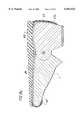
- FIG. 4is a cross section taken along line 4--4 of FIG. 3 showing a first embodiment of the present invention
- FIG. 5is a cross section taken along line 5--5 of FIG. 4;
- FIG. 6is a cross section taken along line 6--6 of FIG. 4;
- FIG. 7is a top plan of a last board used in constructing the shoe of the first embodiment
- FIG. 8is a top plan of an insole used in constructing a shoe of a second embodiment
- FIG. 9is a cross section similar to FIG. 5 but showing the second embodiment of the present invention.
- FIG. 10is a cross section similar to FIG. 4 but showing a third embodiment of the present invention.
- FIG. 11is a cross section similar to FIG. 4 but showing a fourth embodiment of the present invention.
- FIG. 12is a top plan of an orthotic constituting footwear of a fifth embodiment of the present invention.
- FIG. 13is a cross section taken along line 13--13 of FIG. 12;
- FIG. 14is a front elevation of an insert constituting footwear of a sixth embodiment of the present invention.
- FIG. 15is a top plan of a shoe showing the insert of the sixth embodiment installed in a shoe
- FIG. 16is a front elevation of an insert constituting footwear of a seventh embodiment
- FIG. 17is a front elevation of an insert constituting footwear of an eighth embodiment.
- FIGS. 18a-18cdepict steps of a method of making the shoe of the first embodiment.
- a footis designated in its entirety by the reference character F.
- the foot Fhas a heel bone or calcaneus C and an Achilles tendon A extending upward from a rearward end of the heel bone.
- Fluid-filled sacks or bursae Bare positioned in front of and behind the tendon A just above the point where the tendon attaches to the heel bone C.
- the rearward end of the heel bone Cis angled so its lateral posterior portion LP protrudes farther rearward than its medial posterior portion MP.
- FIGS. 3 through 6illustrate a shoe, generally indicated at 20, constituting footwear of a first embodiment of the present invention.
- the shoe 20has a sole (generally indicated at 22) and an upper (generally indicated at 24) attached to the sole about its periphery in a conventional manner.
- the sole 22 and upper 24form a heel cup, generally indicated at 30, at the back of the shoe 20 for receiving the heel of a foot F (not shown).
- the footwear for the first embodimentis a shoe, those skilled in the art will appreciate the present invention applies to other types of footwear such as boots, sandals, orthotics and inserts for use with shoes.
- the sole 22includes an outsole 32 having a lower surface which forms the bottom of the sole, a last board 34 affixed to the upper surface of the outsole and an insole 36 mounted on top of the last board.
- the upper 24includes an outer shell 40 which forms the exterior of the shoe and a liner 42 inside the shell.
- the sole 22 and upper 24 constructionsare conventional and will not be described in further detail.
- the sole 22 and upper 24may have other constructions without departing from the scope of the present invention.
- the upper 24may include a rigid counter (not shown) immediately inside the outer shell 40 for stiffening the upper in the region surrounding the heel cup 30.
- a sockliner(not shown) may be provided over the upper surface of the insole 36.
- FIG. 7illustrates the last board 34 used in constructing the shoe 20 of the first preferred embodiment.
- Two spaced tabs 50a, 50bextend from the rear edge of the last board 34. These tabs 50a, 50b are bent upward as shown in FIG. 5 when the shoe 20 is constructed so they lie between the outer shell 40 and liner 42 of the upper 24.
- a space 52 (FIG. 7) between the tabs 50a, 50bforms a recess 54 at the back of the heel cup 30 which is sized and positioned for receiving the lateral posterior portion LP of the heel bone C, the Achilles tendon A and the associated bursae B as illustrated in FIG. 6 and to reduce pressure on these features.
- the recess 54is offset laterally from a longitudinal axis X bisecting the heel cup 30 so a portion of the foot F corresponding to the lateral posterior portion LP of the heel C protrudes into the recess 54.
- the recess 54may have other widths without departing from the scope of the present invention, in the preferred embodiments, the recess has a width of between approximately 2.5 centimeters (cm) and approximately 3.5 cm, depending on the size of the shoe.
- a centerline Y of the recessis offset from the longitudinal axis X of the heel cup 30 by between about 1.0 cm and about 2.0 cm, depending on the size of the shoe.
- the recess 54may have other depths without departing from the scope of the present invention, in the preferred embodiments, the recess has a depth of between approximately 0.05 cm and approximately 0.10 cm. As will be appreciated by those skilled in the art, these preferred dimensions will vary depending upon the materials used and the size of the shoe. Although other materials may be used without departing from the scope of the present invention, the last board 34 of the first preferred embodiment is made of neoprene, polyvinyl chloride or polyurethane.
- the insole 36has two spaced flaps 60a, 60b similar to the flaps 50a, 50b extending from the last board 34 of the first embodiment.
- the last board 34 of the second embodimentis conventional and does not include the flaps 50a, 50b.
- the flaps 60a, 60b of the insole 36extend up from the insole between the liner 42 and the outer shell 40 of the upper 24.
- the flaps 60a, 60bhave substantially the same dimensions as the flaps 50a, 50b of the first embodiment and are separated by a space 62 having approximately the same width as the space 52 of the first embodiment.
- the space 62 between the flaps 60a, 60b of the insole 36forms a recess (similar to that shown in FIG. 6) at the back of the heel cup 30 which is sized and positioned for receiving the lateral posterior portion LP of the heel bone C, the Achilles tendon A and the associated bursae B.
- the insole 36 of the second preferred embodimentis made of neoprene, polyvinyl chloride or polyurethane having a Shore A durometer of about 35 to about 65 or a Shore C durometer of about 45 to about 65.
- the last board 34 of the second embodimentmay be omitted without departing from the scope of the present invention.
- a third embodiment of the present inventionhas a separate generally U-shaped insert 70 secured between the liner 42 and the outer shell 40 of the upper 24.
- the insert 70comprises two spaced arms 72a, 72b integrally joined by a band 74.
- the facing (opposing) edges of the arms 72a, 72bare spaced apart to provide a recess 76 for receiving the lateral posterior portion LP of the heel bone C, the Achilles tendon A and the associated bursae B.
- the recess 76 of the third embodimentis offset laterally from the longitudinal axis X bisecting the heel cup 30 so a portion of the foot F corresponding to the lateral posterior portion LP of the heel C protrudes into the recess 54.
- the recess 76has a width of between approximately 2.5 cm and approximately 3.5 cm, and the centerline Y of the recess is offset from the longitudinal axis X of the heel cup 30 by between about 1.0 cm and about 2.0 cm, depending on the size of the shoe.
- the recess 76has a depth of approximately 0.05 cm and approximately 0.10 cm, and a height of between approximately 3.5 cm and approximately 4.5 cm, depending on the size of the shoe.
- the insert 70may be made of other materials without departing from the scope of the present invention, the insert of the preferred embodiment is neoprene, polyvinyl chloride or polyurethane having a Shore A durometer of about 35 to about 65 or a Shore C durometer of about 45 to about 65.
- a fourth embodiment of the present inventionincludes a generally rectangular insert 80 secured between the liner 42 and the outer shell 40 of the upper 24.
- the insert 80has a oval opening 82 providing a recess for receiving the lateral posterior portion LP of the heel bone C, the Achilles tendon A and the associated bursae B.
- the oval opening 82 of the fourth preferred embodimentis between about 2.5 cm and about 3.5 cm tall and between about 2.5 cm and about 3.5 cm wide, depending on the size of the shoe.
- the center of the oval opening 82 of the fourth preferred embodimentis positioned between about 2.0 cm and about 2.5 cm above the upper surface of the sole 22 and between about 1.0 cm and about 2.0 cm from the longitudinal axis X of the heel cup 30, depending on the size of the shoe.
- the opening 82is between approximately 0.05 cm and approximately 0.10 cm deep, depending on the size of the shoe.
- the opening 82 of the preferred embodimentextends entirely through the insert 80, openings which extend only partially through the insert are also envisioned as being within the scope of the present invention. It is also contemplated that the opening 82 may be filled with a material which is more easily compressed than the material forming the surrounding portion of the insert 80.
- the filler materialmay be a gel (e.g., a silicone gel), a fluid held in a flexible hollow member or other material that is compliant to accommodate the lateral posterior portion LP of the heel bone C, the Achilles tendon A and the associated bursae B of a wearer's foot F (not shown).
- the insert 80may be made of other materials without departing from the scope of the present invention, the insert of the preferred embodiment is neoprene, polyvinyl chloride or polyurethane having a Shore A durometer of about 35 to about 65 or a Shore C durometer of about 45 to about 65.
- a fifth embodiment of the present inventionshown in FIGS. 12 and 13, comprises an orthotic, generally designated by 90, for placement in a shoe over its insole (not shown).
- the orthotic 90has a conventional inner sole 92 for receiving a foot (not shown).
- a wall 94 surrounding the rearward portion of the inner sole 92forms a heel cup, generally indicated at 96, for receiving the heel of the foot.
- a recess 98 formed in the wall 94is sized and positioned as described above for accommodating the lateral posterior portion LP of the heel bone C, the Achilles tendon A and the associated bursae B of a wearer's foot F (not shown).
- the recess 98is generally U-shaped, similar to the recesses of the first through third embodiments of the present invention, but may have other configurations without departing from the scope of the present invention. For instance, the recess may be oval or have other shapes. Also, the recess may extend entirely through the thickness of the wall.
- the orthotic 90may be made of other materials without departing from the scope of the present invention, the insert of the preferred embodiment is neoprene, polyvinyl chloride or polyurethane having a Shore A durometer of about 35 to about 65 or a Shore C durometer of about 45 to about 65.
- FIGS. 14 and 15illustrate a sixth embodiment of the invention.
- This embodimentcomprises an adhesive backed insert, generally indicated at 100, formed with an opening (e.g., a slot 102) sized and shaped substantially the same as the insert 70 of the third embodiment.
- the insert 100 of the sixth embodimentmay be affixed inside the heel cup 30 of a shoe 20 using its adhesive backing so the centerline Y of the slot 102 is offset from the longitudinal axis X of the heel cup 30 to accommodate the lateral posterior portion LP of the heel as discussed above.
- the insert 100 of the sixth preferred embodimentis made of foam such as neoprene, polyvinyl chloride or polyurethane having a Shore A durometer of about 35 to about 65 or a Shore C durometer of about 45 to about 65.
- An oval or round, adhesive backed insert of a seventh embodiment of the present inventionis generally designated by 110 in FIG. 16.
- the insert 110has an oval opening 112 shaped similarly to the oval opening 82 of the fourth embodiment.
- the insert 110may be positioned inside a shoe (not shown) so the center of the oval opening 112 is positioned between about 2.0 cm and about 2.5 cm above the upper surface of the sole 22 and between about 1.0 cm and about 2.0 cm from the longitudinal axis X of the heel cup 30 (not shown) to accommodate the lateral posterior portion LP of the heel bone C, the Achilles tendon A and the associated bursae B of a wearer's foot F (not shown). These dimensions may vary depending on the specific size of the shoe. Although other materials may be used, the insert 110 of the seventh preferred embodiment is made of foam similar to that of the sixth embodiment.
- FIG. 17An oval or round, adhesive backed insert 120 comprising the eighth embodiment of the present invention is illustrated in FIG. 17.
- the eighth embodimentis identical to the seventh except that the opening 112 is filled with an oval compliant member 124 to accommodate the lateral posterior portion LP of the heel bone C, the Achilles tendon A and the associated bursae B of a wearer's foot F (not shown).
- the compliant member 124 of the eighth preferred embodimentis made of gel similar to that of the fourth embodiment.
- FIGS. 18a-18cdepict steps of a method of making the shoe 20 of the first embodiment.
- a last board 34is temporarily attached to a last (generally designated by L) in a conventional manner (e.g., with staples) as shown in FIG. 18a.
- the tabs 50a, 50b of the last board 34are folded down over the heel portion of the last L, and an outer shell 40 of an upper 24 is slipped into position over the last L and last board as shown in FIG. 18b.
- the margin 130 of the outer shell 40overlies the margin 132 of the last board.
- These margins 130, 132may be attached to each other by any conventional method if desired. As illustrated in FIG.
- a sole 22is attached to the last board 34 and outer shell margin 130 by any conventional means (e.g., stitching and/or gluing).
- any conventional meanse.g., stitching and/or gluing.
- the shoe 20 of the second embodimentis made in much the same way as the shoe of the first embodiment.
- the last board 34 of the second embodimentdoes not have tabs.
- the step of folding the tabs down over the heel portion of the last Lis omitted.
- the last board 34is temporarily attached to the last L, the outer shell 40 is slipped into position over the last and last board, and the sole 22 is attached to the last board and outer shell margin 130 before the partially completed shoe 20 is removed from the last L.
- the tabs 60a, 60bare folded up so they are positioned against the inside of the outer shell 40 or similar structure (e.g., a counter).
- the liner 42is attached to the outer shell 40 so the tabs 60a, 60b of the insole 36 are sandwiched between the liner and the shell.
- the shoes 20 of the third and fourth embodimentsare also made by a somewhat similar method. However, neither the last board 34 nor the insole 36 of these embodiments has tabs. Instead, the last board 34, outer shell 40 and sole 22 are the assembled as described above with respect to the second embodiment.
- the insert (70 or 80)is attached to the inside of the outer shell 40 or similar structure (e.g., a counter) before the liner 42 and insole 36 are inserted into the shoe 20.
Landscapes
- Health & Medical Sciences (AREA)
- Epidemiology (AREA)
- General Health & Medical Sciences (AREA)
- Public Health (AREA)
- Footwear And Its Accessory, Manufacturing Method And Apparatuses (AREA)
Abstract
Description
Claims (11)
Priority Applications (3)
| Application Number | Priority Date | Filing Date | Title |
|---|---|---|---|
| US09/166,357US6041524A (en) | 1998-10-05 | 1998-10-05 | Footwear having recessed heel cup |
| AU65016/99AAU6501699A (en) | 1998-10-05 | 1999-09-28 | Footwear having recessed heel cup |
| PCT/US1999/022475WO2000019850A1 (en) | 1998-10-05 | 1999-09-28 | Footwear having recessed heel cup |
Applications Claiming Priority (1)
| Application Number | Priority Date | Filing Date | Title |
|---|---|---|---|
| US09/166,357US6041524A (en) | 1998-10-05 | 1998-10-05 | Footwear having recessed heel cup |
Publications (1)
| Publication Number | Publication Date |
|---|---|
| US6041524Atrue US6041524A (en) | 2000-03-28 |
Family
ID=22602946
Family Applications (1)
| Application Number | Title | Priority Date | Filing Date |
|---|---|---|---|
| US09/166,357Expired - LifetimeUS6041524A (en) | 1998-10-05 | 1998-10-05 | Footwear having recessed heel cup |
Country Status (3)
| Country | Link |
|---|---|
| US (1) | US6041524A (en) |
| AU (1) | AU6501699A (en) |
| WO (1) | WO2000019850A1 (en) |
Cited By (21)
| Publication number | Priority date | Publication date | Assignee | Title |
|---|---|---|---|---|
| WO2002005672A1 (en) | 2000-07-19 | 2002-01-24 | Kellerman Company Llc | Insole with improved cushioning for sides of feet and heels |
| US6671981B2 (en) | 2000-08-04 | 2004-01-06 | Jeffrey S. Brooks, Inc. | Footwear |
| US20040111923A1 (en)* | 2000-08-04 | 2004-06-17 | Brooks Jeffrey S. | Footwear |
| US20050172424A1 (en)* | 2002-02-07 | 2005-08-11 | Karlheinz Schlecht | Lmt turmor suppressor gene |
| US20050229436A1 (en)* | 2004-04-14 | 2005-10-20 | Samuel Bock | Skate boot |
| US20080072461A1 (en)* | 2006-09-21 | 2008-03-27 | Howlett Harold A | Cushioned orthotic |
| WO2012018744A1 (en)* | 2010-08-02 | 2012-02-09 | Brown Shoe Company, Inc. | Composite sole assembly |
| US8697970B2 (en) | 2009-01-12 | 2014-04-15 | Gavin Harrison | Cymbal mounting assembly |
| GB2511878B (en)* | 2013-03-14 | 2016-02-24 | Hbn Shoe Llc | Heel Stabilizer for footwear |
| US9345287B2 (en) | 2013-03-14 | 2016-05-24 | Hbn Shoe, Llc | Heel stabilizer for footwear |
| US20170172252A1 (en)* | 2015-12-18 | 2017-06-22 | Neale Cody Schindermann | Removable shoe insole |
| US10390587B2 (en) | 2016-03-01 | 2019-08-27 | Hbn Shoe, Llc | Device for high-heeled shoes and method of constructing a high-heeled shoe |
| US10477915B2 (en) | 2016-03-01 | 2019-11-19 | Hbn Shoe, Llc | Device for high-heeled shoes and method of constructing a high-heeled shoe |
| US10702008B2 (en) | 2018-02-26 | 2020-07-07 | Hbn Shoe, Llc | Device and method of constructing shoes |
| US11134863B2 (en) | 2015-10-05 | 2021-10-05 | Scholl's Wellness Company Llc | Generating orthotic product recommendations |
| US11540588B1 (en) | 2021-11-24 | 2023-01-03 | Hbn Shoe, Llc | Footwear insole |
| US11805850B1 (en) | 2023-07-19 | 2023-11-07 | Hbn Shoe, Llc | Cuboid pad |
| US11854058B2 (en) | 2017-10-13 | 2023-12-26 | Scholl's Wellness Company Llc | Footcare product dispensing kiosk |
| US20240324727A1 (en)* | 2023-03-29 | 2024-10-03 | Zilong Wang | Shoe counter structure |
| US12232567B2 (en) | 2021-10-15 | 2025-02-25 | Skechers U.S.A., Inc. Ii | Footwear heel counter for easier foot entry or removal |
| USD1082267S1 (en) | 2024-04-09 | 2025-07-08 | Hbn Shoe, Llc | Shoe insert |
Citations (20)
| Publication number | Priority date | Publication date | Assignee | Title |
|---|---|---|---|---|
| US1020160A (en)* | 1911-09-30 | 1912-03-12 | Lewis S Rowe | Shoe-pad. |
| US1055768A (en)* | 1912-10-07 | 1913-03-11 | Samuel H Levee | Shoe attachment. |
| US1137092A (en)* | 1913-10-31 | 1915-04-27 | Columbus A Sharp | Insole. |
| DE350517C (en)* | 1919-11-16 | 1922-03-21 | Karl Peringer | Hollow wall made of shaped stones that interlock with dovetail-shaped attachments |
| US2119807A (en)* | 1936-01-07 | 1938-06-07 | Myron M Farley | Heel and arch cushion and support |
| US2821032A (en)* | 1954-12-24 | 1958-01-28 | Walk Rite Appliances Proprieta | Orthopedic appliance for flat-footedness |
| FR1222370A (en)* | 1959-04-28 | 1960-06-09 | Fitment insole for all shoes | |
| US3068872A (en)* | 1959-08-11 | 1962-12-18 | Brody Alec Elliot | Foot supporting device |
| US3309797A (en)* | 1964-03-17 | 1967-03-21 | Poitras Joseph Arthur | Anti-inversion device for sneakers |
| US3333353A (en)* | 1963-07-19 | 1967-08-01 | Garcia Pedro Arnau | Manufacture of footwear |
| US4272899A (en)* | 1979-10-15 | 1981-06-16 | Brooks Jeffrey S | Footwear |
| US4435910A (en)* | 1982-03-12 | 1984-03-13 | Michel Marc | Shoe insole |
| US4503576A (en)* | 1981-08-19 | 1985-03-12 | Brown Dennis N | Orthotic appliance and method of making |
| US4627178A (en)* | 1983-02-28 | 1986-12-09 | Sullivan James B | Molded shoe innersole |
| US4702255A (en)* | 1985-06-17 | 1987-10-27 | Schenkl Joseph L | Orthopedic apparatus |
| US4726126A (en)* | 1985-06-10 | 1988-02-23 | Puma Ag Rudolf Dassler Sport | Shoe, particularly intended for rehabilitation purposes |
| US4739765A (en)* | 1985-06-28 | 1988-04-26 | Bio Balance Orthotics Inc. | Arch support |
| US4869001A (en)* | 1986-03-07 | 1989-09-26 | Superfeet In-Shoe Systems, Inc. | Foot and ankle orthotic for a skate boot or the like, and method |
| US4879821A (en)* | 1987-09-04 | 1989-11-14 | Hyde Athletic Industries Inc. | Insole construction |
| US4901390A (en)* | 1988-09-26 | 1990-02-20 | Dynamic Foam Products, Inc. | Method of manufacturing custom insoles for athletic shoes |
Family Cites Families (2)
| Publication number | Priority date | Publication date | Assignee | Title |
|---|---|---|---|---|
| US912579A (en)* | 1908-05-09 | 1909-02-16 | Frederick W Krech | Heel-pad. |
| US1958619A (en)* | 1933-02-17 | 1934-05-15 | Harris L Handler | Nonslip cushion pad for shoe counters |
- 1998
- 1998-10-05USUS09/166,357patent/US6041524A/ennot_activeExpired - Lifetime
- 1999
- 1999-09-28WOPCT/US1999/022475patent/WO2000019850A1/enactiveApplication Filing
- 1999-09-28AUAU65016/99Apatent/AU6501699A/ennot_activeAbandoned
Patent Citations (20)
| Publication number | Priority date | Publication date | Assignee | Title |
|---|---|---|---|---|
| US1020160A (en)* | 1911-09-30 | 1912-03-12 | Lewis S Rowe | Shoe-pad. |
| US1055768A (en)* | 1912-10-07 | 1913-03-11 | Samuel H Levee | Shoe attachment. |
| US1137092A (en)* | 1913-10-31 | 1915-04-27 | Columbus A Sharp | Insole. |
| DE350517C (en)* | 1919-11-16 | 1922-03-21 | Karl Peringer | Hollow wall made of shaped stones that interlock with dovetail-shaped attachments |
| US2119807A (en)* | 1936-01-07 | 1938-06-07 | Myron M Farley | Heel and arch cushion and support |
| US2821032A (en)* | 1954-12-24 | 1958-01-28 | Walk Rite Appliances Proprieta | Orthopedic appliance for flat-footedness |
| FR1222370A (en)* | 1959-04-28 | 1960-06-09 | Fitment insole for all shoes | |
| US3068872A (en)* | 1959-08-11 | 1962-12-18 | Brody Alec Elliot | Foot supporting device |
| US3333353A (en)* | 1963-07-19 | 1967-08-01 | Garcia Pedro Arnau | Manufacture of footwear |
| US3309797A (en)* | 1964-03-17 | 1967-03-21 | Poitras Joseph Arthur | Anti-inversion device for sneakers |
| US4272899A (en)* | 1979-10-15 | 1981-06-16 | Brooks Jeffrey S | Footwear |
| US4503576A (en)* | 1981-08-19 | 1985-03-12 | Brown Dennis N | Orthotic appliance and method of making |
| US4435910A (en)* | 1982-03-12 | 1984-03-13 | Michel Marc | Shoe insole |
| US4627178A (en)* | 1983-02-28 | 1986-12-09 | Sullivan James B | Molded shoe innersole |
| US4726126A (en)* | 1985-06-10 | 1988-02-23 | Puma Ag Rudolf Dassler Sport | Shoe, particularly intended for rehabilitation purposes |
| US4702255A (en)* | 1985-06-17 | 1987-10-27 | Schenkl Joseph L | Orthopedic apparatus |
| US4739765A (en)* | 1985-06-28 | 1988-04-26 | Bio Balance Orthotics Inc. | Arch support |
| US4869001A (en)* | 1986-03-07 | 1989-09-26 | Superfeet In-Shoe Systems, Inc. | Foot and ankle orthotic for a skate boot or the like, and method |
| US4879821A (en)* | 1987-09-04 | 1989-11-14 | Hyde Athletic Industries Inc. | Insole construction |
| US4901390A (en)* | 1988-09-26 | 1990-02-20 | Dynamic Foam Products, Inc. | Method of manufacturing custom insoles for athletic shoes |
Non-Patent Citations (34)
| Title |
|---|
| AliMed advertisement Your best single source . . . in Podiatry Today Jul./Aug. 1997, p. 43.* |
| AliMed® advertisement "Your best single source . . . " in "Podiatry Today" Jul./Aug. 1997, p. 43. |
| Allied OSI Labs advertisement Allied OSI Footlights are Light in Price in Podiatry Today Jul./Aug. 1997, p. 84.* |
| Bauerfeind advertisement Viscoheel , the viscoelastic heel cushions . . . in Biomechanics Jan. 1997, p. 57.* |
| Bauerfeind advertisement"Viscoheel®, the viscoelastic heel cushions . . . " in "Biomechanics" Jan. 1997, p. 57. |
| Bio Orthopaedic Laboratory advertisement Standard Foot Orthotics and The Foot Store advertisement The Best Kind of Support . . . in Biomechanics Sep. 1995, p. 76.* |
| Biomechanics Jun. 1997, p. 87.* |
| Bio-Orthopaedic Laboratory advertisement "Standard Foot Orthotics" and The Foot Store advertisement "The Best Kind of Support . . . " in "Biomechanics" Sep. 1995, p. 76. |
| Bird & Cronin Inc. advertisement "A Complete Line of Pre-Molded Silicone Foot Orthotics" in "Biomechanics" Jun. 1997, p. 44. |
| Bird & Cronin Inc. advertisement A Complete Line of Pre Molded Silicone Foot Orthotics in Biomechanics Jun. 1997, p. 44.* |
| Bloch Orthotic Labs advertisement "Shelling Out Too Much for Orthotics?" in "Podiatric Products" Sep. 1994, p. 10. |
| Bloch Orthotic Labs advertisement Shelling Out Too Much for Orthotics in Podiatric Products Sep. 1994, p. 10.* |
| Bolt Systems, Inc. advertisement Quality Prefabricated Orthopedic Appliances in Biomechanics Jun. 1997, p. 74.* |
| CJ Foot Orthotics advertisement All This For Less in Podiatry Management Jun. 1996, p. 101.* |
| Comed advertisement The Power of 78 in Podiatry Today Oct. 1993, p. 39.* |
| Darco advertisement "The One Stop Footcare Shop!" in "Biomechanics" Sep. 1995, p. 18. |
| Darco advertisement The One Stop Footcare Shop in Biomechanics Sep. 1995, p. 18.* |
| Dr. Scholl s advertisement Now Your Patients are One Step Closer to Pain Relief in Podiatry Today Jul./Aug. 1997, p. 33.* |
| Dr. Scholl's® advertisement "Now Your Patients are One Step Closer to Pain Relief" in "Podiatry Today" Jul./Aug. 1997, p. 33. |
| IEM Medical Technologies, Inc. advertisement "Sorbothane II® Heel Cups" in "Biomechanics" Sep. 1995, p. 66. |
| IEM Medical Technologies, Inc. advertisement Sorbothane II Heel Cups in Biomechanics Sep. 1995, p. 66.* |
| Ipos Orthopedics North America Inc. advertisment "Soft-Base Soft-Ipocon" in "Podiatric Products" Sep. 1994, p. 37. |
| Ipos Orthopedics North America Inc. advertisment Soft Base Soft Ipocon in Podiatric Products Sep. 1994, p. 37.* |
| Johnson & Johnson advertisement Johnson & Johnson Biomechanics in Biomechanics Sep. 1995, p. 1.* |
| M F Athletic Company advertisement If Achilles was Alive, He d Want a Pair of M F Heel Protectors in Podiatric Products Sep. 1994, p. 55.* |
| M-F Athletic Company advertisement "If Achilles was Alive, He'd Want a Pair of M-F Heel Protectors!" in "Podiatric Products" Sep. 1994, p. 55. |
| Ortho Dynactive, Inc. advertisement Tread Lightly in Biomechanics Jan. 1997, p. 71.* |
| Ortho-Dynactive, Inc. advertisement "Tread Lightly" in "Biomechanics" Jan. 1997, p. 71. |
| Performance Materials Corporation advertisement Into the Deep Blue in Podiatry Today Jul./Aug. 1997, p. 44.* |
| Riecken s Orthotic Laboratory advertisement Our Dealers Become Old Friends . . . in Biomechancis Sep. 1995, p. 16.* |
| Riecken's Orthotic Laboratory advertisement "Our Dealers Become Old Friends . . . " in "Biomechancis" Sep. 1995, p. 16. |
| STJ Orthotic Services Inc. advertisement Your Heel Pain Patients will be Floating on Water in Podiatry Management Jun. 1996, p. 1* |
| The Elford Group Ltd. advertisement "Nothing Fits Like SOCS™" in "Podiatry Management" Jun. 1996, p. 47. |
| The Elford Group Ltd. advertisement Nothing Fits Like SOCS in Podiatry Management Jun. 1996, p. 47.* |
Cited By (33)
| Publication number | Priority date | Publication date | Assignee | Title |
|---|---|---|---|---|
| WO2002005672A1 (en) | 2000-07-19 | 2002-01-24 | Kellerman Company Llc | Insole with improved cushioning for sides of feet and heels |
| US6671981B2 (en) | 2000-08-04 | 2004-01-06 | Jeffrey S. Brooks, Inc. | Footwear |
| US20040111923A1 (en)* | 2000-08-04 | 2004-06-17 | Brooks Jeffrey S. | Footwear |
| US7028419B2 (en) | 2000-08-04 | 2006-04-18 | Jeffrey S. Brooks, Inc. | Footwear |
| US20050172424A1 (en)* | 2002-02-07 | 2005-08-11 | Karlheinz Schlecht | Lmt turmor suppressor gene |
| US20050229436A1 (en)* | 2004-04-14 | 2005-10-20 | Samuel Bock | Skate boot |
| WO2005104892A3 (en)* | 2004-04-14 | 2007-07-26 | George Thorpe | Improved skate boot |
| US7325813B2 (en)* | 2004-04-14 | 2008-02-05 | Samuel Bock | Skate boot |
| US20080072461A1 (en)* | 2006-09-21 | 2008-03-27 | Howlett Harold A | Cushioned orthotic |
| US7958653B2 (en) | 2006-09-21 | 2011-06-14 | Schering-Plough Healthcare Products, Inc. | Cushioned orthotic |
| US8800169B2 (en) | 2006-09-21 | 2014-08-12 | Msd Consumer Care, Inc. | Cushioned orthotic |
| US8697970B2 (en) | 2009-01-12 | 2014-04-15 | Gavin Harrison | Cymbal mounting assembly |
| WO2012018744A1 (en)* | 2010-08-02 | 2012-02-09 | Brown Shoe Company, Inc. | Composite sole assembly |
| GB2511878B (en)* | 2013-03-14 | 2016-02-24 | Hbn Shoe Llc | Heel Stabilizer for footwear |
| US9345287B2 (en) | 2013-03-14 | 2016-05-24 | Hbn Shoe, Llc | Heel stabilizer for footwear |
| US11134863B2 (en) | 2015-10-05 | 2021-10-05 | Scholl's Wellness Company Llc | Generating orthotic product recommendations |
| US20170172252A1 (en)* | 2015-12-18 | 2017-06-22 | Neale Cody Schindermann | Removable shoe insole |
| US10390587B2 (en) | 2016-03-01 | 2019-08-27 | Hbn Shoe, Llc | Device for high-heeled shoes and method of constructing a high-heeled shoe |
| US10729205B2 (en) | 2016-03-01 | 2020-08-04 | Hbn Shoe, Llc | Device for high-heeled shoes and method of constructing a high-heeled shoe |
| US10477915B2 (en) | 2016-03-01 | 2019-11-19 | Hbn Shoe, Llc | Device for high-heeled shoes and method of constructing a high-heeled shoe |
| US11854058B2 (en) | 2017-10-13 | 2023-12-26 | Scholl's Wellness Company Llc | Footcare product dispensing kiosk |
| US10702008B2 (en) | 2018-02-26 | 2020-07-07 | Hbn Shoe, Llc | Device and method of constructing shoes |
| US12408732B2 (en) | 2021-10-15 | 2025-09-09 | Skechers U.S.A., Inc. Ii | Footwear heel counter for easier foot entry or removal |
| US12419386B2 (en) | 2021-10-15 | 2025-09-23 | Skechers U.S.A., Inc. Ii | Footwear heel counter for easier foot entry or removal |
| US12232567B2 (en) | 2021-10-15 | 2025-02-25 | Skechers U.S.A., Inc. Ii | Footwear heel counter for easier foot entry or removal |
| US12285076B2 (en) | 2021-10-15 | 2025-04-29 | Skechers U.S.A., Inc. Ii | Footwear heel counter for easier foot entry or removal |
| US12414608B2 (en) | 2021-10-15 | 2025-09-16 | Skechers U.S.A., Inc. Ii | Footwear heel counter for easier foot entry or removal |
| US12336594B2 (en) | 2021-10-15 | 2025-06-24 | Skechers U.S.A., Inc. Ii | Footwear heel counter for easier foot entry or removal |
| US11540588B1 (en) | 2021-11-24 | 2023-01-03 | Hbn Shoe, Llc | Footwear insole |
| US20240324727A1 (en)* | 2023-03-29 | 2024-10-03 | Zilong Wang | Shoe counter structure |
| US12295458B2 (en)* | 2023-03-29 | 2025-05-13 | Zilong Wang | Shoe counter structure |
| US11805850B1 (en) | 2023-07-19 | 2023-11-07 | Hbn Shoe, Llc | Cuboid pad |
| USD1082267S1 (en) | 2024-04-09 | 2025-07-08 | Hbn Shoe, Llc | Shoe insert |
Also Published As
| Publication number | Publication date |
|---|---|
| WO2000019850A9 (en) | 2000-09-08 |
| WO2000019850A1 (en) | 2000-04-13 |
| AU6501699A (en) | 2000-04-26 |
Similar Documents
| Publication | Publication Date | Title |
|---|---|---|
| US6041524A (en) | Footwear having recessed heel cup | |
| EP0925000B2 (en) | Shoe having an internal chassis | |
| EP1915067B1 (en) | Shoe insole | |
| US6922919B2 (en) | Sport footwear component construction | |
| US7322132B2 (en) | Device for high-heeled shoes and method of constructing a high-heeled shoe | |
| US8215036B2 (en) | Removable heel bucket | |
| EP2481312A1 (en) | Tri-Planar support system for footwear | |
| EP3426086B1 (en) | Footwear arch support | |
| KR20120085780A (en) | Shoe with support system | |
| RU2671062C2 (en) | Shoe | |
| JP2004535211A (en) | Shoe structure | |
| WO2000016653A1 (en) | Shoe having internal midsole | |
| CN100502714C (en) | Apparatus for high-heeled shoes and method of constructing high-heeled shoes | |
| CA2292997C (en) | Sport footwear component construction | |
| HK1254997A1 (en) | Device for high-heeled shoes and method of constructing a high-heeled shoe | |
| HK1109031B (en) | Device for high-heeled shoes and method of constructing a high-heeled shoe | |
| HK1116368B (en) | Shoe insole | |
| HK1171923A (en) | Shoe insole | |
| HK1139017A1 (en) | High-heeled shoes | |
| HK1139017B (en) | High-heeled shoes |
Legal Events
| Date | Code | Title | Description |
|---|---|---|---|
| AS | Assignment | Owner name:JEFFREY S. BROOKS, INC., MISSOURI Free format text:ASSIGNMENT OF ASSIGNORS INTEREST;ASSIGNOR:BROOKS, JEFFREY S.;REEL/FRAME:009497/0907 Effective date:19981002 | |
| FEPP | Fee payment procedure | Free format text:ENTITY STATUS SET TO UNDISCOUNTED (ORIGINAL EVENT CODE: BIG.); ENTITY STATUS OF PATENT OWNER: SMALL ENTITY | |
| STCF | Information on status: patent grant | Free format text:PATENTED CASE | |
| FEPP | Fee payment procedure | Free format text:PAT HOLDER CLAIMS SMALL ENTITY STATUS, ENTITY STATUS SET TO SMALL (ORIGINAL EVENT CODE: LTOS); ENTITY STATUS OF PATENT OWNER: SMALL ENTITY Free format text:PAYOR NUMBER ASSIGNED (ORIGINAL EVENT CODE: ASPN); ENTITY STATUS OF PATENT OWNER: SMALL ENTITY | |
| FPAY | Fee payment | Year of fee payment:4 | |
| AS | Assignment | Owner name:DR. BROOKS INNOVATIONS, LLC, MISSOURI Free format text:ASSIGNMENT OF ASSIGNORS INTEREST;ASSIGNOR:JEFFREY S. BROOKS, INC.;REEL/FRAME:017823/0474 Effective date:20060621 | |
| FEPP | Fee payment procedure | Free format text:PAT HOLDER NO LONGER CLAIMS SMALL ENTITY STATUS, ENTITY STATUS SET TO UNDISCOUNTED (ORIGINAL EVENT CODE: STOL); ENTITY STATUS OF PATENT OWNER: SMALL ENTITY | |
| FPAY | Fee payment | Year of fee payment:8 | |
| REMI | Maintenance fee reminder mailed | ||
| FEPP | Fee payment procedure | Free format text:PAT HOLDER CLAIMS SMALL ENTITY STATUS, ENTITY STATUS SET TO SMALL (ORIGINAL EVENT CODE: LTOS); ENTITY STATUS OF PATENT OWNER: SMALL ENTITY | |
| FPAY | Fee payment | Year of fee payment:12 | |
| SULP | Surcharge for late payment | Year of fee payment:11 | |
| AS | Assignment | Owner name:BROOKS, JEFFREY S., MISSOURI Free format text:ASSIGNMENT OF ASSIGNORS INTEREST;ASSIGNOR:DR. BROOKS INNOVATIONS, LLC;REEL/FRAME:028241/0829 Effective date:20120516 |